Electricalconduction in ceramics - unipd.it · Electricalconduction in ceramics ... Defects The...
27
Electrical conduction in ceramics Prof. Antonella Glisenti - Dip. Scienze Chimiche - Università degli Studi di Padova Laurea Magistrale in Scienza dei Materiali Materiali Inorganici Funzionali
-
Upload
nguyenmien -
Category
Documents
-
view
231 -
download
0
Transcript of Electricalconduction in ceramics - unipd.it · Electricalconduction in ceramics ... Defects The...

Electrical conductionin ceramics
Prof. Antonella Glisenti - Dip. Scienze Chimiche - Università degli Studi di Padova
Laurea Magistrale in Scienza dei Materiali
Materiali Inorganici Funzionali
Conductivity in oxides
DefectsDefects and dopingDefects and oxygenDefects in fluorite-type oxidesConductivity in MO2-type oxides

Bibliography
1. P. J. van der Put: The inorganic chemistry of materials – How to make things out of elements – Plenum Press 1998
2. N.Q. Minh, T. Takahashi: Science and technology of ceramic fuel cells – Elsevier 1995
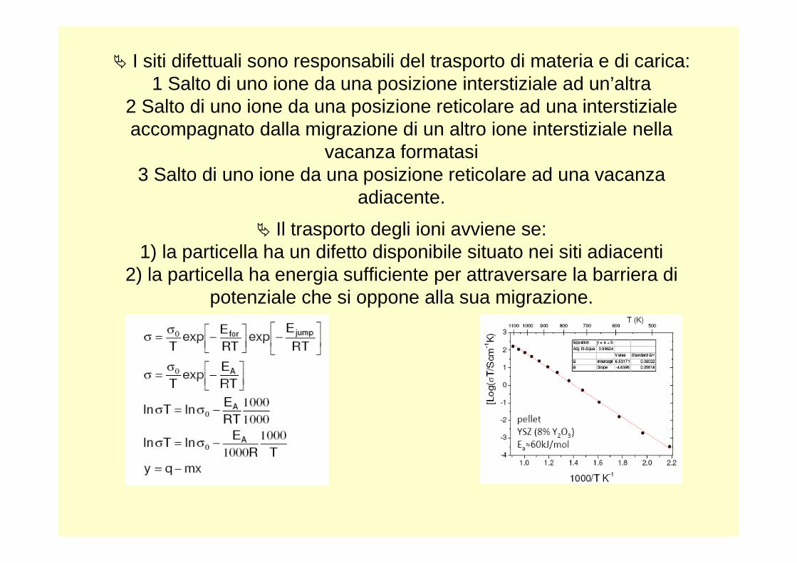
� I siti difettuali sono responsabili del trasporto di materia e di carica:1 Salto di uno ione da una posizione interstiziale ad un’altra
2 Salto di uno ione da una posizione reticolare ad una interstiziale accompagnato dalla migrazione di un altro ione interstiziale nella
vacanza formatasi3 Salto di uno ione da una posizione reticolare ad una vacanza
adiacente.
� Il trasporto degli ioni avviene se:1) la particella ha un difetto disponibile situato nei siti adiacenti
2) la particella ha energia sufficiente per attraversare la barriera di potenziale che si oppone alla sua migrazione.

Defects
The properties of ceramics or crystalline solids depends on the material lattice defects.
StoichiometryStoichiometric defects: crystal composition is unchangedNon-stoichiometric defects: crystal composition changes
Size and ShapePoint defects: interstitials or vacancies
Line defects: dislocationsPlane defects: the whole layer in a crystal structure is defective
Electrical conduction in ceramics or crystalline solids depends on point defects.

Types of defects in solids
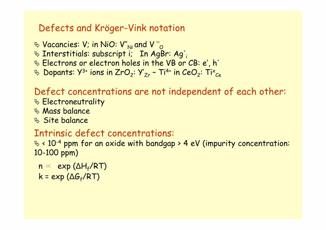
Defects and Kröger-Vink notation
� Vacancies: V; in NiO: V’’Ni and V ¨O � Interstitials: subscript i; In AgBr: Ag˙i� Electrons or electron holes in the VB or CB: e’, h˙� Dopants: Y3+ ions in ZrO2: Y’Zr – Ti4+ in CeO2: TixCe
Defect concentrations are not independent of each other:� Electroneutrality� Mass balance� Site balance
Intrinsic defect concentrations:� < 10-4 ppm for an oxide with bandgap > 4 eV (impurity concentration: 10-100 ppm)
n Q exp (∆Hf/RT)k = exp (∆Gf/RT)

Frenkel-type defects (1926): interstitials and vacanciesFrenkel defects move in the crystal
N = total number of ions; Ni = total number of interstitials; k = Boltzmann constant, T = temperature, EF = formation energy of the Frenkel defects)
� the radii of ions of the crystal differ considerably � high van der Waals energy and dielectric constant
Schottky-type defects (1935): cation/anion vacanciesN = total number of ion pairs; Ni = total number of Schottkydefects; k = Boltzmann constant, T = temperature, ES = formation energy of the Schottky defects)
� Small differences between the radii of the cations and anions� Poor polarizability� Small van der Waals energy and dielectric constant
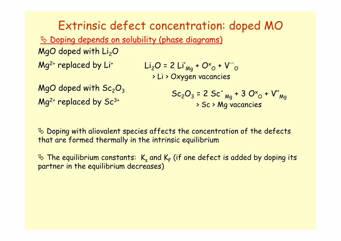
Extrinsic defect concentration: doped MO
MgO doped with Li2O
� Doping with aliovalent species affects the concentration of the defects that are formed thermally in the intrinsic equilibrium
� The equilibrium constants: Ks and KF (if one defect is added by doping its partner in the equilibrium decreases)
� Doping depends on solubility (phase diagrams)
Mg2+ replaced by Li+ Li2O = 2 Li’Mg + OxO + V¨O
> Li > Oxygen vacancies
Sc2O3 = 2 Sc˙Mg + 3 OxO + V’’Mg
> Sc > Mg vacancies
MgO doped with Sc2O3
Mg2+ replaced by Sc3+
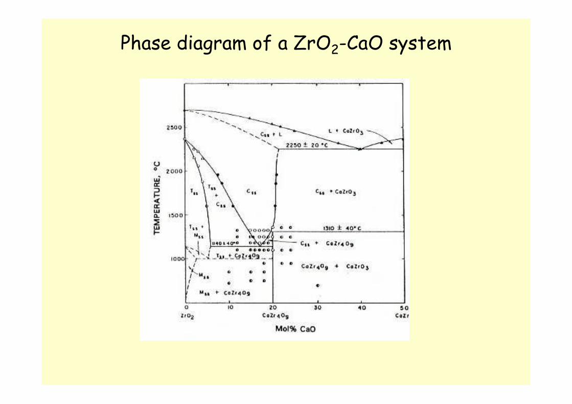
Phase diagram of a ZrO2-CaO system
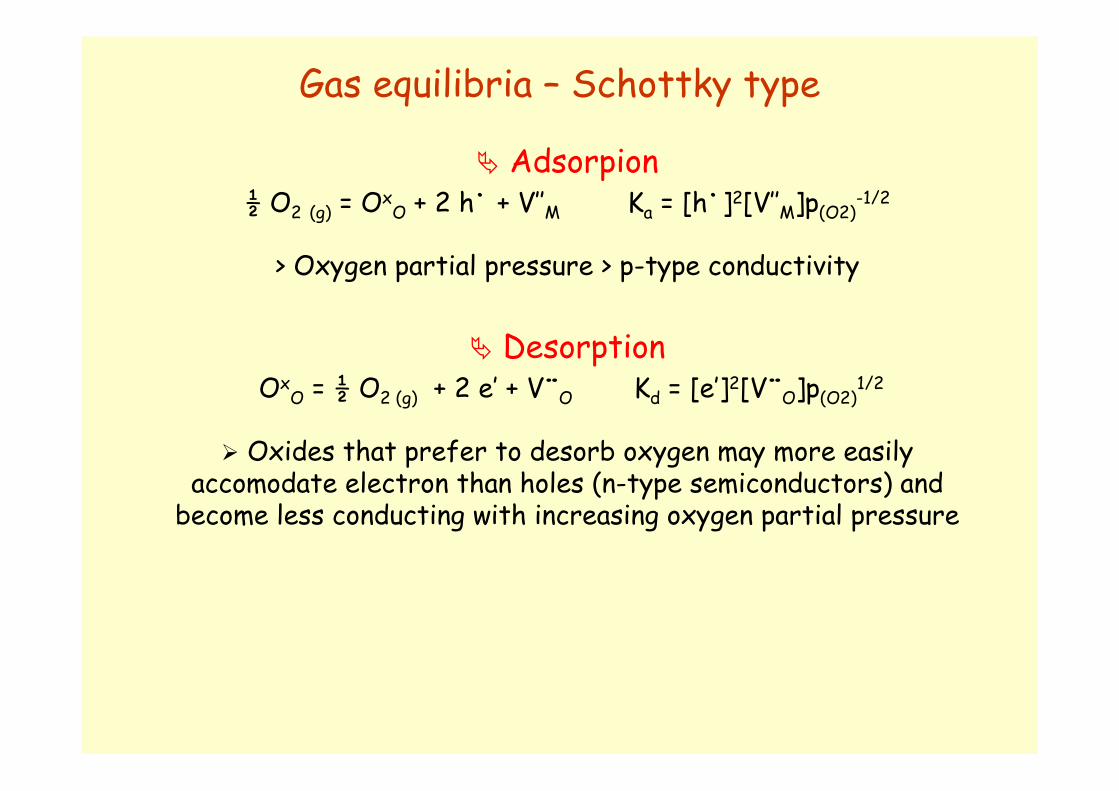
� Adsorpion½ O2 (g) = Ox
O + 2 h˙ + V’’M Ka = [h˙]2[V’’M]p(O2)-1/2
> Oxygen partial pressure > p-type conductivity
� DesorptionOx
O = ½ O2 (g) + 2 e’ + V¨O Kd = [e’]2[V¨O]p(O2)1/2
� Oxides that prefer to desorb oxygen may more easilyaccomodate electron than holes (n-type semiconductors) and
become less conducting with increasing oxygen partial pressure
Gas equilibria – Schottky type
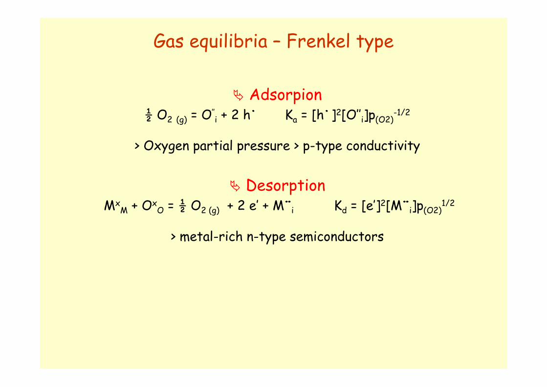
� Adsorpion½ O2 (g) = O’’
i + 2 h˙ Ka = [h˙]2[O’’i]p(O2)-1/2
> Oxygen partial pressure > p-type conductivity
� DesorptionMx
M + OxO = ½ O2 (g) + 2 e’ + M¨i Kd = [e’]2[M¨i]p(O2)1/2
> metal-rich n-type semiconductors
Gas equilibria – Frenkel type

Ki « KSOxides with a wide bandgap: the oxide is a pure ionic conductor under an oxygen pressure at the middle region
Ki » KSOxides with a narrow bandgap: the oxide is a semiconductor at all oxygen pressures (low oxygen pressures = n-type, high oxygen pressure = p-type)
Calculated equilibrium defect diagrams for a binary oxide MO with Schottky defect pairs
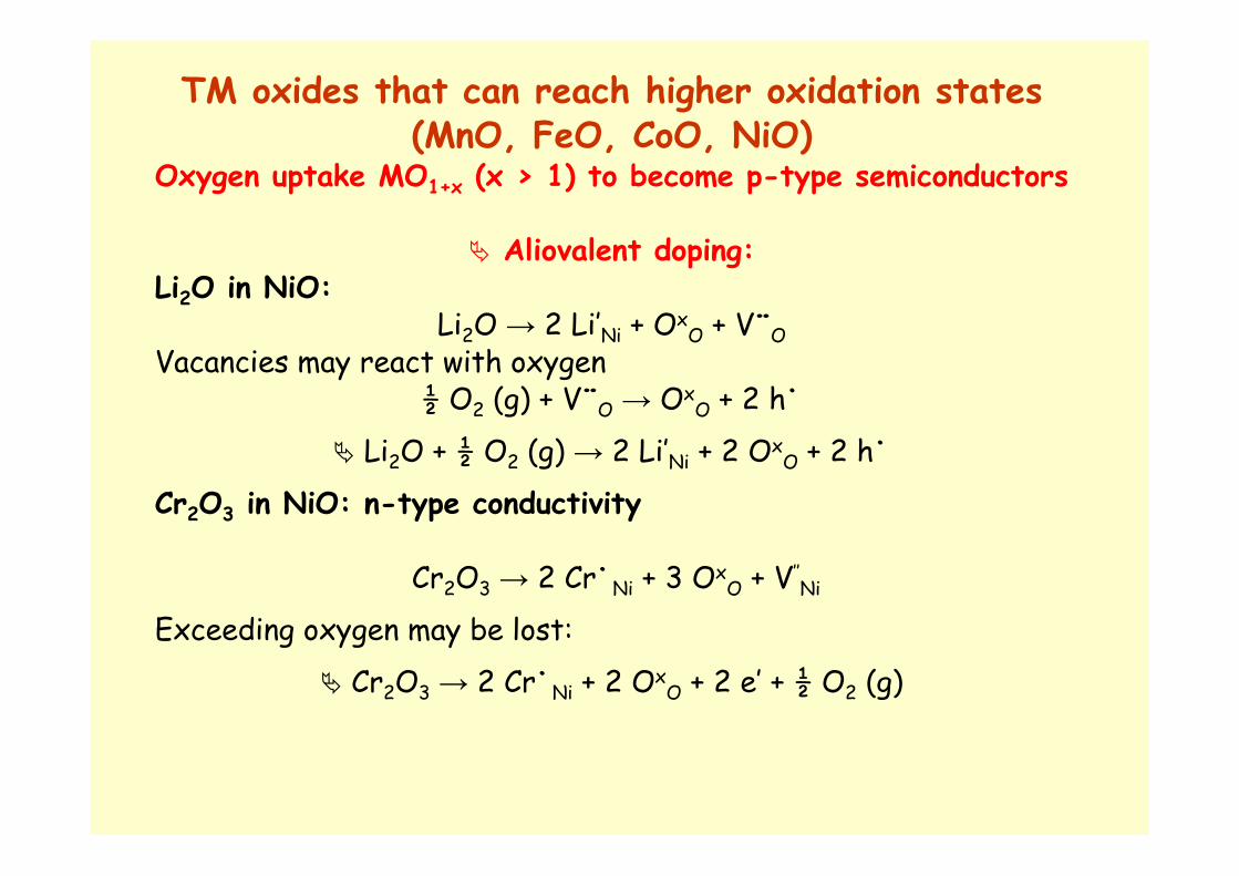
TM oxides that can reach higher oxidation states(MnO, FeO, CoO, NiO)
Oxygen uptake MO1+x (x > 1) to become p-type semiconductors
� Aliovalent doping:Li2O in NiO:
Li2O → 2 Li’Ni + OxO + V¨O
Vacancies may react with oxygen½ O2 (g) + V¨O → Ox
O + 2 h˙
� Li2O + ½ O2 (g) → 2 Li’Ni + 2 OxO + 2 h˙
Cr2O3 in NiO: n-type conductivity
Cr2O3 → 2 Cr˙Ni + 3 OxO + V’’
Ni
Exceeding oxygen may be lost:
� Cr2O3 → 2 Cr˙Ni + 2 OxO + 2 e’ + ½ O2 (g)

TM oxides that can not reach higher oxidation states(Ta2O5, CeO2, ZnO)
Oxygen desorption MO1+x (x < 1) to become n-type semiconductors
� Aliovalent doping:Li2O in ZnO:
Li2O → 2 Li’Zn + OxO + V¨O
Vacancies may react with oxygen
� Li2O + ½ O2 (g) + 2e’→ 2 Li’Zn + 2 OxO
Li doping oxidizes ZnO and lowers its n-type conductivity by consumingthe surplus electrons in the conduction band
Cr2O3 in ZnO: n-type conductivity
Cr2O3 → 2 Cr˙Zn + 2 OxO + 2e’ + ½ O2(g)
Doping ZnO with cromium oxide that has too many oxide ions for ZnOevolves gaseous oxygen that leaves electrons behind; n-type characterof ZnO is increased

Defects in fluorite-type oxides The fluorite (CaF2) structure is adopted by a number of oxides (MO2 with M = large tetravalent cation), sulfides, hydrides, intermetallic compounds of AX2 type
Defects in doped zirconia with fluorite structure:1) oxygen-ion vacancies with the metal ions being fixed at their lattice points2) cation interstitials with oxygen ions being fixed at their lattice sites (Frenkel)3) Schottky
�Unit cell (=M4O8 structure): each metal ion is surrounded by eight oxygen ions forming a body-centred cubic structure, and each oxygen ion is surrounded by four metal ions forming a tetrahedral arrangement.
The minimum metal-ion radius/oxygen-ion radius is 0.732
At RT ZrO2 has not a fluorite structure (ionic radius ratio condition not satisfied); fluorite structure is observed at T > 2370°C or when stabilized by aliovalent doping (divalent or trivalent cations)

Defect structure of doped MO2Incorporation of AO into MO2:
Incorporation of oxygen from the environment into MO2:
Equilibrium constant, K:
Intrinsic Schottky equilibrium:
Equilibrium constant, KS:
Intrinsic electronic equilibrium:
Equilibrium constant, Ki:
Electroneutrality condition:
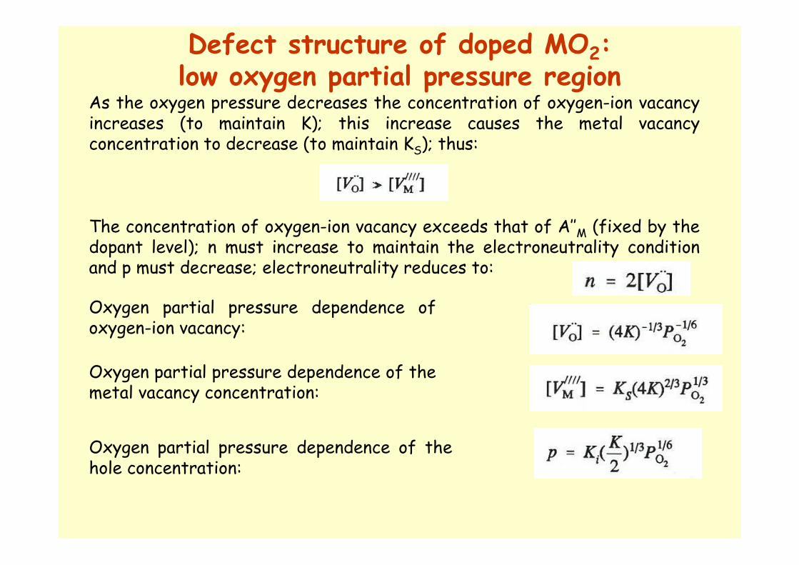
Defect structure of doped MO2:low oxygen partial pressure region
As the oxygen pressure decreases the concentration of oxygen-ion vacancy increases (to maintain K); this increase causes the metal vacancy concentration to decrease (to maintain KS); thus:
The concentration of oxygen-ion vacancy exceeds that of A’’M (fixed by the dopant level); n must increase to maintain the electroneutrality condition and p must decrease; electroneutrality reduces to:
Oxygen partial pressure dependence of oxygen-ion vacancy:
Oxygen partial pressure dependence of the metal vacancy concentration:
Oxygen partial pressure dependence of the hole concentration:
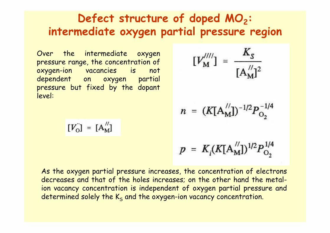
Defect structure of doped MO2:intermediate oxygen partial pressure region
Over the intermediate oxygen pressure range, the concentration of oxygen-ion vacancies is not dependent on oxygen partial pressure but fixed by the dopantlevel:
As the oxygen partial pressure increases, the concentration of electrons decreases and that of the holes increases; on the other hand the metal-ion vacancy concentration is independent of oxygen partial pressure and determined solely the KS and the oxygen-ion vacancy concentration.

Defect structure of doped MO2:high oxygen partial pressure region
Oxygen partial pressure dependence of the anion and cation vacancies:
Electron concentration is constant in this oxygen partial pressure region.
Electroneutrality condition con be approximated as:
Electron concentration is given by:
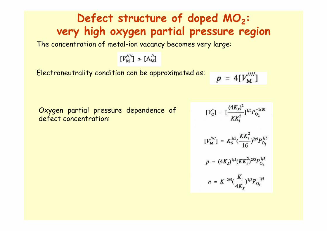
Defect structure of doped MO2:very high oxygen partial pressure region
Oxygen partial pressure dependence of defect concentration:
The concentration of metal-ion vacancy becomes very large:
Electroneutrality condition con be approximated as:

Defect structure of AO and B2O3 doped MO2Variation of defect concentration as a function of oxygen partial pressure for a MO2-AO system
Variation of defect concentration as a
function of oxygen partial pressure for a MO2-B2O3
system

Conductivities of oxygen ions, electrons, and electron holes
µ = mobilities; i, n, p = ions, electrons, electron holes;
the ionic conductivity due to the migration of cations of the dopants and the host is neglected because the mobilities of the cations have been shown by diffusivity measurements to be several order of magnitude lower than the mobility of oxygen-ion vacancy.
The total electrical conductivity, σ, of a fluorite-type oxide is given as:
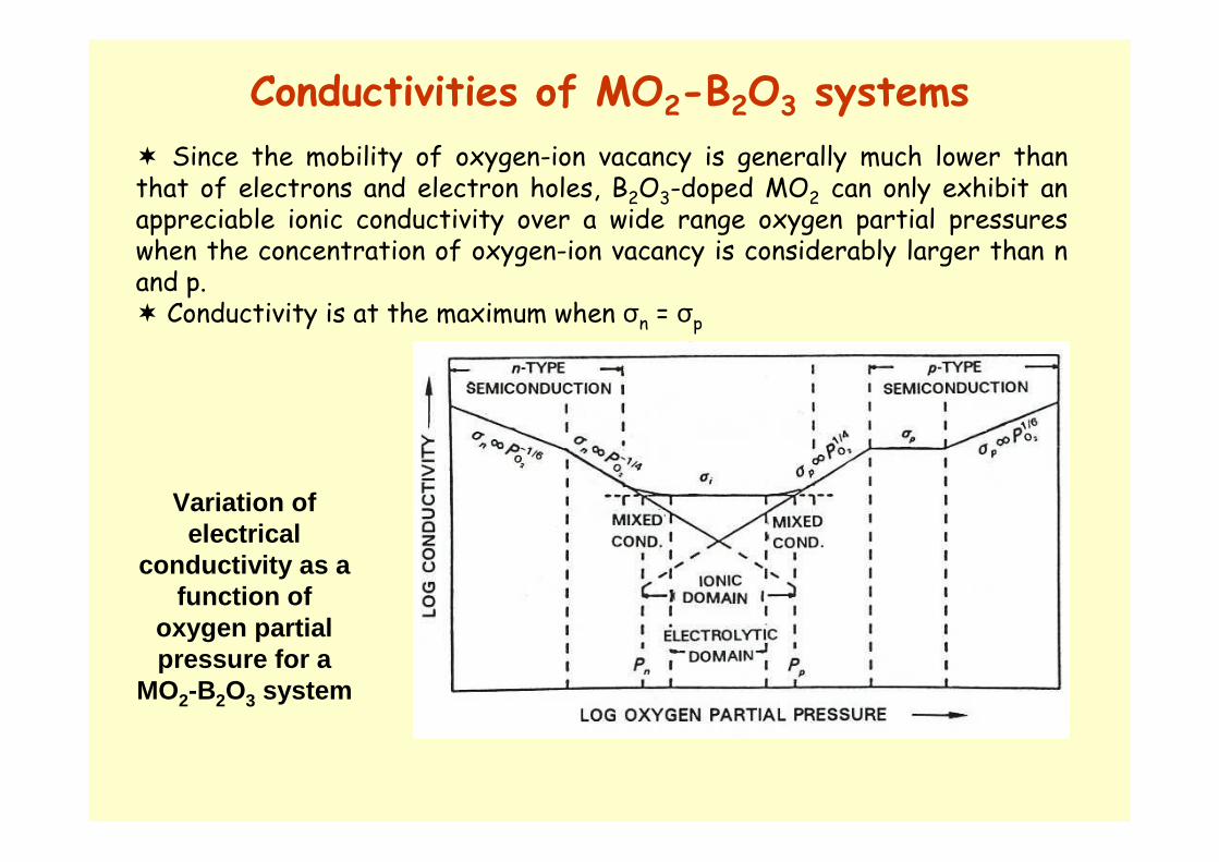
Conductivities of MO2-B2O3 systems
� Since the mobility of oxygen-ion vacancy is generally much lower than that of electrons and electron holes, B2O3-doped MO2 can only exhibit an appreciable ionic conductivity over a wide range oxygen partial pressures when the concentration of oxygen-ion vacancy is considerably larger than n and p. � Conductivity is at the maximum when σn = σp
Variation of electrical
conductivity as a function of
oxygen partial pressure for a
MO2-B2O3 system
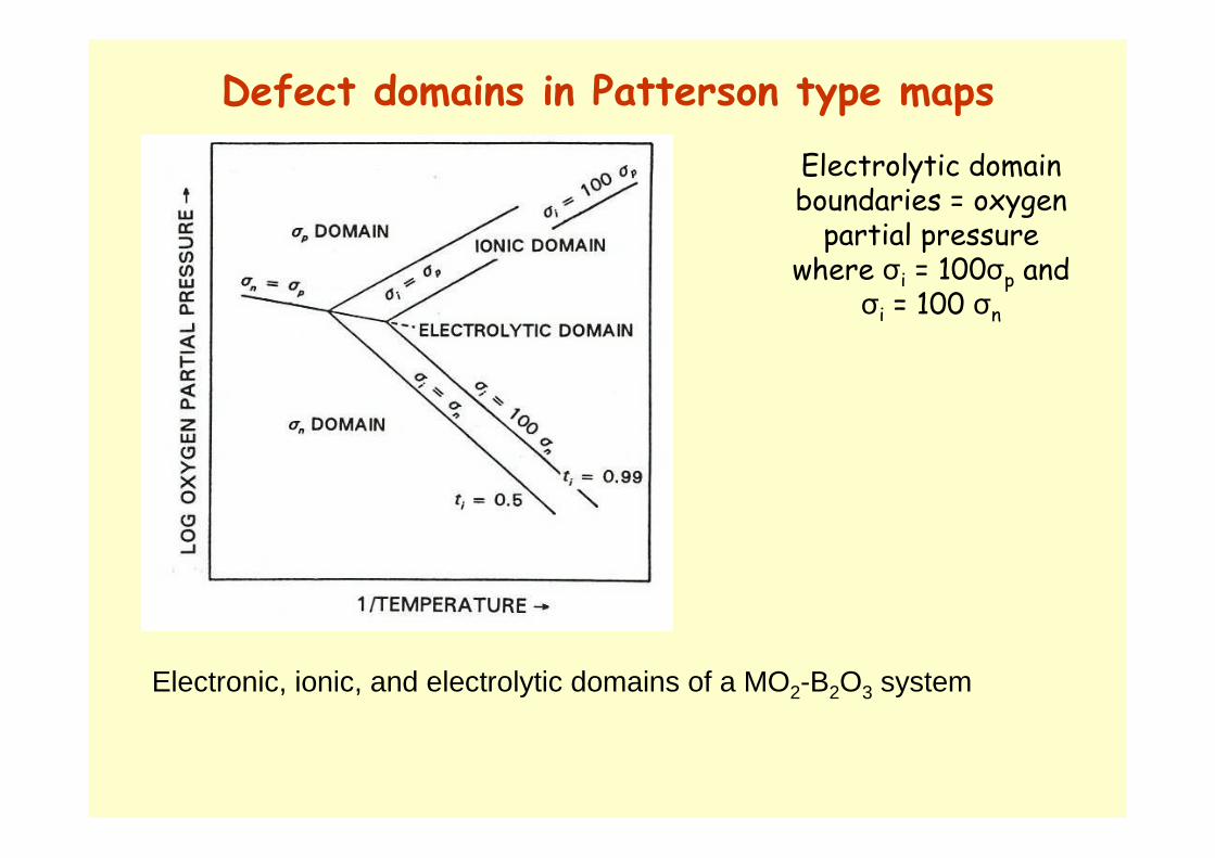
Defect domains in Patterson type maps
Electronic, ionic, and electrolytic domains of a MO2-B2O3 system
Electrolytic domain boundaries = oxygen partial pressure
where σi = 100σp and σi = 100 σn
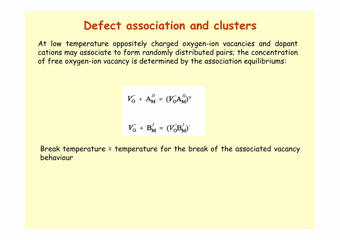
Defect association and clusters
At low temperature oppositely charged oxygen-ion vacancies and dopantcations may associate to form randomly distributed pairs; the concentration of free oxygen-ion vacancy is determined by the association equilibriums:
Break temperature = temperature for the break of the associated vacancy behaviour
Defect association and clusters
2. At high defect concentration a random distribution of defects and defect pairs may be converted into an ordered two- or three-dimensional defect structure
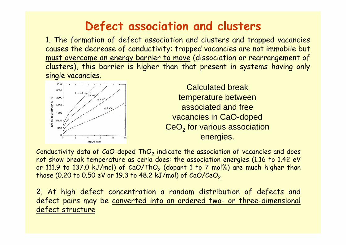
1. The formation of defect association and clusters and trapped vacancies causes the decrease of conductivity: trapped vacancies are not immobile but must overcome an energy barrier to move (dissociation or rearrangement of clusters), this barrier is higher than that present in systems having only single vacancies.
Calculated break temperature between associated and free
vacancies in CaO-doped CeO2 for various association
energies.
Conductivity data of CaO-doped ThO2 indicate the association of vacancies and does not show break temperature as ceria does: the association energies (1.16 to 1.42 eVor 111.9 to 137.0 kJ/mol) of CaO/ThO2 (dopant 1 to 7 mol%) are much higher than those (0.20 to 0.50 eV or 19.3 to 48.2 kJ/mol) of CaO/CeO2


![Module 3: Defects, Diffusion and Conduction in Ceramics ...nptel.ac.in/courses/113104005/lecture_pdf/module3.pdf · existence of electrical potential gradients, ... 03:41 PM] Module](https://static.fdocuments.net/doc/165x107/5a79da8d7f8b9a880c8da17e/module-3-defects-diffusion-and-conduction-in-ceramics-nptelacincourses113104005lecturepdf.jpg)