ULTRA HIGH CYCLE FATIGUE PROPERTIES OF SINTERED …
22
Powder Metallurgy Progress, Vol.1 (2001), No 1 19 ULTRA HIGH CYCLE FATIGUE PROPERTIES OF SINTERED STEELS H. Danninger, B. Weiss Abstract Low alloy PM steels Fe-1.5%Mo-0.7%C were used as a model material for studying high cycle fatigue of sintered steels. Ultrasonic fatigue testing was done in the push-pull mode at 20 kHz up to N>10 8 . It showed that the fatigue endurance limit strongly depends on the total porosity but also on the sintering temperature. For predicting the fatigue limit, the load bearing cross section A c was found to be well suited which microstructural parameter can be measured in low-deformation fracture surfaces. In the matrix, homogeneous Mo distribution gives better results than heterogeneous one and heat treatment improves the fatigue endurance compared to the as-sintered state especially at high loading cycle numbers. Singular defects such as slag inclusions or larger pores lower the fatigue endurance the more the better the basic performance of the material is. Kitagawa diagrams are well suited to predict the effect of singular defects if possible interactions between defects are taken into account. Keywords: sintered steel, high cycle fatigue, ultrasonic testing, porosity INTRODUCTION Powder metallurgy precision parts have seen considerable change in their range of applications in recent years [1]. Previously for PM parts used in large scale, especially in the automotive industry, the main focus was towards geometrical complexity and precision, and the mechanical properties were of minor importance [2]. Nowadays, in contrast, there is a large number of parts subjected to high mechanical loads in service, esp. those used in automotive engines and transmissions [3-5]. If the actual loading of these components is studied in more detail it is noteworthy that there is a dominance of fatigue and wear; the mechanical properties available in contrast are focusing on monotonic properties such as tensile and yield strength, elongation etc. that are easy to measure but are of limited value for assessing PM automotive parts. In the last decades there has been consistently increasing interest in the fatigue behaviour of PM steels, and various aspects of fatigue loading have been studied, although the focus has been on the high cycle fatigue properties since the loading cycle numbers for typical engine parts such as e.g. connecting rods can easily exceed 10 8 cycles. There have been differing approaches, both from the behaviour of components in service (e.g. [6, 7]) – in which case the material is regarded as a continuum – and from the material viewpoint taking into account the microstructural peculiarities of sintered ferrous components (e.g. [8, 9]). Herbert Danninger, Technische Universität Wien, Institut für Chemische Technologie anorganischer Stoffe Wien, Austria Brigitte Weiss, Universität Wien, Institut für Materialphysik, Wien, Austria
Transcript of ULTRA HIGH CYCLE FATIGUE PROPERTIES OF SINTERED …

Powder Metallurgy Progress, Vol.1 (2001), No 1 19
ULTRA HIGH CYCLE FATIGUE PROPERTIES OF SINTERED STEELS
H. Danninger, B. Weiss
Abstract Low alloy PM steels Fe-1.5%Mo-0.7%C were used as a model material for studying high cycle fatigue of sintered steels. Ultrasonic fatigue testing was done in the push-pull mode at 20 kHz up to N>108. It showed that the fatigue endurance limit strongly depends on the total porosity but also on the sintering temperature. For predicting the fatigue limit, the load bearing cross section Ac was found to be well suited which microstructural parameter can be measured in low-deformation fracture surfaces. In the matrix, homogeneous Mo distribution gives better results than heterogeneous one and heat treatment improves the fatigue endurance compared to the as-sintered state especially at high loading cycle numbers. Singular defects such as slag inclusions or larger pores lower the fatigue endurance the more the better the basic performance of the material is. Kitagawa diagrams are well suited to predict the effect of singular defects if possible interactions between defects are taken into account. Keywords: sintered steel, high cycle fatigue, ultrasonic testing, porosity
INTRODUCTION Powder metallurgy precision parts have seen considerable change in their range of
applications in recent years [1]. Previously for PM parts used in large scale, especially in the automotive industry, the main focus was towards geometrical complexity and precision, and the mechanical properties were of minor importance [2]. Nowadays, in contrast, there is a large number of parts subjected to high mechanical loads in service, esp. those used in automotive engines and transmissions [3-5]. If the actual loading of these components is studied in more detail it is noteworthy that there is a dominance of fatigue and wear; the mechanical properties available in contrast are focusing on monotonic properties such as tensile and yield strength, elongation etc. that are easy to measure but are of limited value for assessing PM automotive parts.
In the last decades there has been consistently increasing interest in the fatigue behaviour of PM steels, and various aspects of fatigue loading have been studied, although the focus has been on the high cycle fatigue properties since the loading cycle numbers for typical engine parts such as e.g. connecting rods can easily exceed 108 cycles. There have been differing approaches, both from the behaviour of components in service (e.g. [6, 7]) – in which case the material is regarded as a continuum – and from the material viewpoint taking into account the microstructural peculiarities of sintered ferrous components (e.g. [8, 9]).
Herbert Danninger, Technische Universität Wien, Institut für Chemische Technologie anorganischer Stoffe Wien, Austria Brigitte Weiss, Universität Wien, Institut für Materialphysik, Wien, Austria

Powder Metallurgy Progress, Vol.1 (2001), No 1 20
Here the various concepts and results given in the literature are described, and experimental results for a sort of “model” material, i.e. a Mo alloy high strength steel, are given as related to the microstructural parameters.
REVIEW OF LITERATURE Not surprisingly, the fatigue behaviour of PM steels has been a focus of attention
quite early, but the number of authors publishing about this topic has been rather low well into the 1980s. Generally, comparison of fatigue data from the literature suffers from the problem of poor comparability due to different testing conditions such as loading mode, mean stress, testing frequency, and maximum loading cycle number which makes data such as “fatigue endurance strength 210 MPa” virtually useless if not precise details of the testing conditions are given. This problem holds for all types of fatigue data. With PM steels the situation is however still more complex since the parameters related to the material are also more numerous than with wrought steels [10]. In addition to composition and heat treatment state, also the total porosity, the pore shape, and the microstructural homogeneity, i.e. the distribution of the alloy elements, all influence the mechanical behaviour [11].
Cyclic stress-strain response/low cycle fatigue Since fatigue crack initiation is usually caused by microplasticity, studying the
cyclic stress-plane strain response is helpful for obtaining a more basic understanding of the fatigue behaviour of such microstructures. This holds in particular for sintered materials in which microplastic deformation can occur at the sintering contacts already at comparatively low stresses (as shown e.g. in [12, 13]. Work published so far has been concentrating on sintered plain iron, some Fe-X alloys, and on austenitic stainless steels [14-17]. For the latter, localization of strain at the sintering contacts leads to inhomogeneous deformation and strain hardening that is more pronounced than in wrought stainless steels; the structural changes in the vicinity of pores have been shown e.g. by electron channeling contrast [18]. So far the findings have been of only moderate relevance in practice e.g. for automotive parts. For LCF, several authors described the fatigue process of PM-Fe using various stages of damage such as e.g. nucleation of microcracks, the appearance of slip bands, and final failure in the LCF regime. Fatigue life data presented as Coffin-Manson plots have been reported on phosphorus alloy steel, Ni-Mo steels and some austenitic steels. A summary of LCF parameters of various ferrous PM materials can be found in [11].
High cycle fatigue As stated above, for pressed and sintered precision parts which are primarily
employed in automobiles, fatigue loading is characterized by high numbers of loading cycles, typically exceeding 108 for engine parts.
Therefore most fatigue data can be found as conventional S-N curves (see [11]). In most of the early work, S-N curves have been obtained under rotating bending loading. More recently, fatigue tests have been carried out in various loading modes such as tension/compression, reverse plane bending, and to some extent also torsion. Buxbaum and Sonsino [19] found that bending and rotation bending result in higher fatigue limit values than does axial loading. Mellanby [20] on the other hand states that for hot repressed Fe-0.3C there is hardly any influence of the loading mode.
The literature data on fatigue strength (defined as the endurance limit or the fatigue limit for N=> 108 ) show large differences for nominally identical materials. These differences are at least in part due to unspecified testing conditions such as specimen

Powder Metallurgy Progress, Vol.1 (2001), No 1 21 geometry, surface condition and number of loading cycles. Fatigue endurance strength is a very critical parameter for structural PM parts. Thus data given in the literature are more difficult to compare to one another than with wrought materials due to the additional parameter to be considered as described above. Today, fatigue data for the industrially frequently used pressed and sintered PM materials are give e.g. for plain Fe and for various types of alloy steels such as Fe-Cu-C, Fe-Ni-Cu-C, Fe-Mo-C.
Already in 1968, Kravic [21] found that the fatigue limit of sintered iron and steel is influenced by the density (i.e. the total porosity), notches, and also heat treatment.
Now it is generally agreed that the fatigue properties are affected most strongly by the porosity: at least for unnotched specimens the fatigue strength is significantly lowered with increasing porosity; due to lower load bearing cross section and the almost unknown notch effects caused by the size, shape, and distribution of the pores. In the case of sintered plain iron it was found that the relationship between total porosity and fatigue endurance strength is comparable to that of the tensile strength and Young´s modulus [22]. Rutz et al. [23] state that the correlation between the tensile strength and the fatigue properties with PM steels is very loose, but both are increased at higher density.
There is also a strong effect of the sintering parameters, especially in the low to moderate porosity range. Nevertheless, earlier equations for predicting the fatigue endurance strength have been based mainly on the total porosity. A similar rather simple approach was recently selected by Bergmark [24] who assumed that total strain is the critical factor for crack initiation and therefore directly related the fatigue endurance strength to the Young’s modulus E. Using McAdam’s equation for the Young’s modulus [25], Bergmark described the fatigue endurance strength exclusively as a function of the relative density (i.e. the total porosity) using an empirical coefficient taken from McAdam. This approach is surely too simplified since it does not consider the microstructure as such, esp. the role of pore morphology and connectivity (which are heavily influenced by the sintering parameters) as well as microstructural heterogeneity; however this approach can be useful for the designer to estimate the change of Sw with varying porosity for a given material and sintering treatment.
The total porosity also affects the pore connectivity, at higher porosity levels the pores being mostly interconnected [26, 27] while at low porosity levels isolated pores prevail [28, 29]. Ledoux and Prioul [30] found that fatigue endurance strength and surface roughness are almost linearly correlated to the open porosity (which however is not necessarily identical to the interconnected one).
There is also a strong effect of the sintering parameters, especially in the low to moderate porosity range. This influence can be split up into the effect on the pore structure and on the matrix microstructure. Sintering at higher temperatures and/or for longer times results in pore rounding and, in the intermediate to low porosity range (P = 5 … 15%), in transition from interconnected to isolated pores [22] which also affects the fatigue behaviour [31]. The effect on the matrix microstructure is noticeable in particular when using mixed or diffusion bonded starting powders since microstructural homogeneity is strongly affected by the sintering parameters (e.g. [32]). Of course, separation of the pore effect and the homogeneity effect is difficult in practice, and for studying the effect of the pores, materials with homogeneous microstructure are better suited. For these materials, such as plain iron or prealloyed steels, the beneficial effect especially of higher sintering temperatures has been shown to advantage [23].
The pore structure of PM steels – and thus the fatigue behaviour – can also be influenced through using starting powders of different particle size [33]. For plain iron this was e.g. investigated by [30, 34]. For Cu and Ni alloyed carbon steels, Christian and

Powder Metallurgy Progress, Vol.1 (2001), No 1 22 German [35] found that finer powders result in higher fatigue strength values, due to smaller and more rounded pores. On the other hand Beiss states that for Cu alloy steels, variation of particle size and shape only results in about 5% changes of the fatigue endurance strength [36].
Generally, the effect of porosity is lower with notched specimens than with smooth ones, i.e. sintered steels are less notch sensitive than wrought ones (similar to cast iron) because of the presence of pores as internal notches [6, 37]. With regard to the microstructural homogeneity there are different opinions: In [38] the heterogeneous microstructure of steels prepared from diffusion bonded Ni-Cu-Mo alloy powders was described to be better than a similar homogeneous one prepared from Ni-Mo prealloy powder. This was attributed to slower crack growth in the former material due to the retarding effect of Ni-rich – retained austenite - areas on crack growth. Higher sintering temperature in this special case is stated to be not advantageous, resulting rather in martensitic than austenitic Ni-rich areas. (It has however been stated that steels prepared e.g. from diffusion bonded powders exhibit better fatigue strength at higher sintering temperatures [39, 40]). On the other hand the softer areas in heterogeneous materials can act as sites for preferential crack initiation, as described for the soft ferritic islands found in Distaloy AE-C in [41]. For a Cu alloyed steel superior properties were found with homogeneous material [42].
Various post-sintering treatments were also found to affect the fatigue endurance strength (e.g. [43]. This can be stated for heat treatment by quenching and tempering. Sonsino [44] compared diffusion bonded Ni-Cu-Mo alloy steel, as sintered, and prealloyed Mo steel, as heat treated, and found that heat treated Astaloy is slightly superior to as-sintered Distaloy material. Surface hardening by carbonitriding was also found to be very effective with Fe-Cu steels [6] and Distaloy types [45]. With Mo alloyed steels, plasmanitriding showed to improve the fatigue limit in the rotation bending mode [46]. Surface treatment by shot peening is particularly effective with sintered steels since it not only results in compressive stresses in the surface region but also in considerable densification [47]. Of course all the surface hardening techniques are more effective in case of bending loads than with axial loading.
Fatigue crack growth behaviour and fracture mechanical considerations In porous PM steels fatigue cracks grow faster than in wrought steels in the Paris
regime but not in the near threshold range [6]. PM steels are therefore well competitive in the near threshold stress range, i.e. for HCF applications, rather than for LCF ones. Bergmark [24] gives the same dependence of ΔKth on the Young’s modulus as for Sw, based on the McAdam equation. On the other hand, for heat treated high strength steel the threshold stress intensity factor - i.e the fracture mechanical endurance strength – was found to be less affected by the total porosity than the unnotched Sw [48]. If the lower density of porous materials is considered, the value for ΔKth/ρ may even be higher for porous steels than for non porous ones which further illustrates the lower notch/crack sensitivity of PM materials.
Limited data are available on the ΔKtheff measurements (e.g. [48]) which take into account the closure effects although this parameter can be regarded more of a true material property than is ΔKth which is strongly affected by the mean stress applied and by external parameters.

Powder Metallurgy Progress, Vol.1 (2001), No 1 23
Sites of crack initiation This occurs frequently at the surface but also internal or semi-internal locations
can be found, e.g. at pore clusters or at regions where, due to packing inhomogeneities or uneven pressure distribution during compacting, the total porosity is slightly higher locally [49]. Beiss and co-workers [50] systematically studied the pore size distribution in different types of sintered steels and found that only the 2% of the largest pores show a satisfactory relationship to the fatigue endurance strength which can be taken as an indication that crack initiation at these large pores limits the fatigue endurance of sintered steels. Other initiation sites are larger singular pores that are generated from alloy element particles during sintering through emergence of transient liquid phase [51-53]. Also slag inclusions / oxide particles are encountered which are just as detrimental if they are - totally or partially - reduced since reduced oxides leave spongy structures behind. The effect of singular defects on the fatigue strength has been studied e.g. in [54, 55], esp. for fully dense PM materials such as superalloys [56] or high strength lightweight Al and Ti materials [57]. In microstructurally heterogeneous sintered steels of Distaloy type it has been shown that the pores are not necessarily the sites of crack initiation but that also soft areas such as ferritic particle cores cause crack initiation [41]. In this case apparently the high alloy sintering contact areas have higher specific strength and therefore are not the weakest areas in the microstructure despite of their lower cross section.
In general, the multitude of materials, manufacturing parameters, and testing conditions obscures the relationships between the important parameters and the fatigue properties. For the work presented here, it was therefore decided to use a single material and a single testing procedure in order to work out the effect of manufacturing and microstructure on the high cycle fatigue properties of high strength PM steel.
EXPERIMENTAL DETAILS For the work described here, a high strength Mo alloy steel was used, which had
been studied in detail previously [52, 53]. Mostly prealloy powder was used, in order to eliminate possible effects of the microstructure and to show the effects of the pores more clearly. The steel of the composition Fe -1.5%Mo- 0.7%C was prepared from prealloyed powder Astaloy Mo (Fe-1.5 mass% Mo, Höganäs AB). For some experiments also water atomized plain iron powder (ASC 100.29, Höganäs) and elemental Mo powder <32 µm were used. Carbon was added as fine natural graphite (UF4), and 0.5% Microwax C was admixed as lubricant. The powders were then blended for 1 hr in a tumbling mixer and compacted in a pressing tool with floating die to form rectangular specimens 100 x 10 x ~10 mm.
These compacts were separately de-waxed in flowing hydrogen for 30 min at 600°C. In part, double pressing was applied, dewaxing also performing the intermediate anneal. The bars were then sintered in an industrial batch vacuum furnace under rotary pump vacuum, the heating and cooling rates being 10 K.min-1 each. Part of the double pressed specimens were completely densified by HIP for 3 hrs at 1100oC, the pressure being 200 MPa. The attained density was 7.881 g.cm-3 (which was also taken as the value for fully dense material to calculate the porosity of the sintered specimens). The sintered bars were in part machined to form dumbbell shaped fatigue specimens (Fig.2b). Since it was intended to investigate the material related effects rather than the geometrical ones, unnotched specimens (Kt = 1) were tested. After turning, part of the as-sintered or as-HIPed specimens were heat treated by austenitizing at 860oC for 45 min, oil quenching, and tempering at 400oC for 60 min. The microstructures obtained were rather coarse upper bainite after sintering and fine tempered martensite after heat treatment (Fig.1). With both

Powder Metallurgy Progress, Vol.1 (2001), No 1 24 as-sintered and heat treated specimens the testing zones were ground and then longitudinally polished.
a) as-sintered b) quenched and tempered Fig.1. Microstructures of Fe-1.5%Mo-0.7%C; prealloyed powder; sintered 60 min 1280°C in vacuum
Fatigue testing was carried out with an ultrasonic resonance system operating at 20 kHz with zero mean stress (R = 1) as schematically shown in Fig.2a [58]. To keep the specimen temperature constant despite heating effects due to damping, permanent cooling by means of a drilling oil emulsion was performed. The tests were carried out up to 2.108 cycles, in special cases up to 109 cycles. Standard S-N curves were taken, with at least 12 bars per curve being tested.
In the case of ultrasonic testing, the question of significance of the results for standard fatigue loaded components – usual frequencies being 10…200 Hz - arises. Test runs with different types of sintered steels tested in parallel at 40 Hz and 20 kHz, respectively, have shown that while there is a pronounced influence of the testing frequency at high stresses – probably due to strain rate sensitivity effects – in the case of stresses near the endurance limit quite satisfactory agreement exists [59]. I.e. for components that are HCF loaded, the fatigue endurance strength measured through ultrasonic testing should be well applicable.
For determination of the fatigue crack growth behaviour and esp. the threshold stress intensity factors ΔKth and ΔKtheff, the same ultrasonic resonance test system was used, and crack growth was observed through optical microscopy. The specimens were machined as given in Fig.2c, and a lens-shaped notch (2 mm x 0.2 mm) was applied by electric discharge machining to one flat side. The respective specimen was fixed to the ultrasonic test system, and the strain amplitude was gradually increased until crack growth was observed. The crack was then allowed to grow until the crack tip had attained sufficient distance from the notch (about half the notch length). Then the stress amplitude was gradually reduced until crack growth could not be observed any more. If the crack did not grow within N = 107, the respective stress intensity factor range was regarded to be the threshold value ΔKth which was calculated according to [60]. Details of testing can be found elsewhere (e.g. [60]).
It is well known that ΔKth by itself is not well suited for describing the crack growth behaviour, being strongly affected e.g. by the R value. Thus closure effects have to be taken into account [61, 62], and also the effective value ΔKtheff had to be determined here. Closure effects were measured by applying a strain gage across the crack tip and

Powder Metallurgy Progress, Vol.1 (2001), No 1 25 measuring stress-crack opening curves starting from very small stress amplitudes. The effective threshold values were calculated as described in [63]. The conventional approach is that loads below the closure point of a crack do not affect crack propagation any more [62]. It has been shown however that this is not generally true but that also loads below the opening load have to be taken into consideration [63]. If this is done, this new ΔKth,eff can be regarded virtually as a material property.
a) Schematic of fatigue testing device (installation for crack growth testing; for S-N curves emulsion cooling applied)
b) Dumbbell shaped specimens for fatigue endurance testing
c) Flat bars for fatigue crack growth measurement
Fig.2. Schematic of ultrasonic fatigue testing device and shapes of specimens for push-pull fatigue testing and for fatigue crack growth measurement, respectively
INFLUENCE OF THE RELATIVE DENSITY / TOTAL POROSITY The most important single parameter with PM precision parts is their relative
density, i.e. total porosity. It has been shown frequently (e.g. [29, 64, 65]) that the porosity affects the mechanical properties much more than would be expected from the volume fraction of the pores. With ferrous precision parts, which, in order to maintain shape and dimensional stability, should be sintered without marked dimensional change, total porosity is mainly affected by the compacting process, and sintering exerts only slight influence.

Powder Metallurgy Progress, Vol.1 (2001), No 1 26
Here, specimens with varying total porosity were produced by varying the compacting pressure from 150 MPa to 700 MPa; furthermore, higher density was attained by double pressing as described above, the pressures applied being 700 MPa each. (The uncommonly wide range of compacting pressures and resulting porosity levels, far exceeding that of practically useful materials, was selected in order to give information about a really comprehensive range of porous sintered steels). The green compacts were then vacuum sintered at 1270°C for 2 hrs; one batch of double pressed and sintered samples was virtually fully densified by HIP. All specimens were finally heat treated by quenching and tempering. Metallographic investigations showed that by using prealloyed Fe-Mo powder, evenly distributed porosity was attained with all the materials [66], and fatigue fracture caused by secondary pores [51] was most improbable here. Thus the fatigue endurance strength values obtained should be caused by the effect of the "primary" pores originating from the green compact.
Fatigue testing was done as described above, the runs being carried out up to Nmax = 2.108 cycles. All S-N curves tended to level out at N>107 which indicates the existence of a true fatigue limit, although fracture was found to occur also in the cycle range N>107 , and the term “fatigue limit” is therefore doubtful for results obtained at e.g. N = 107. It was observed that surprisingly the shape of the curves was virtually identical for HIPed and for high porosity specimens, as shown in Fig.3 which depicts the curves, the stress values being shown normalized to the respective fatigue limit. This can be taken as a clue that the fatigue behaviour of the macroscopically brittle highly porous sintered steels is still comparable to that of fully dense steels rather than to that of not only macroscopically but also microscopically brittle materials such as ceramics. These latter materials exhibit fairly flat S-N curves, with extremely pronounced effect of the stress amplitude on the lifetime [67]. With the porous steels, in contrast, the effect of the stress amplitude on the lifetime is not higher than in the case of the fully dense HIPed specimens. It can thus be assumed that not only the crack initiation – as with brittle materials - but also crack propagation determine the lifetime of the materials, due to the ability of the porous steels to exhibit microplastic - if not macroplastic – deformation, and is in agreement with findings that in sintered materials cracks are generated during fatigue loading anyhow [68] and it is only a question if they are propagating or not [69].
Fig.3. S-N curves of Fe-1.5%Mo-0.7%C (heat treated), normalized to the respective fatigue limit. Sintered 2 hrs at 1280°C, heat treated
Fig.4. Fatigue endurance strength (Nmax = 2.108) of Fe-1.5%Mo-0.7%C as a function of the total porosity. Sintered 2 hrs at 1280°C, heat treated

Powder Metallurgy Progress, Vol.1 (2001), No 1 27
Optical investigation of the fracture surfaces showed that these become increasingly rugged at higher porosity levels. Thus, also the area of crack initiation which is discernible normally as being particularly smooth, is more difficult to identify. Generally however it was found that with low density specimens, crack initiation occurs predominantly at or near the surfaces [34, 70], originating in zones of slightly higher porosity. In the porosity range below about 15%, also crack initiation within the specimens was observed (which of course can be found only in the case of push-pull mode). Crack initiation occurred mainly at singularities such as larger, isolated pores or also at pore clusters, i.e. in areas where due to slightly higher porosity zones of fully interconnected porosity exist while the remaining material contains at least predominantly isolated pores [22, 71]. Slight local variations in the porosity distribution thus seem to be of critical importance for fatigue crack initiation especially in the low to medium porosity range.
In Fig.4, the fatigue endurance limit is shown as a function of the total porosity which is in good agreement with the trend postulated by Zapf in [72] and also agrees with respective results obtained with plain iron and PM steel [22, 73]. The somewhat surprising result is that the relative effect of the porosity on the fatigue limit is quite comparable for such widely different materials as high strength steel and plain iron, at least in the case of the sintering parameters chosen here.
The double pressed materials show somewhat lower Sw than would be expected, indicating maybe some damage caused during second pressing [74]. As with other dynamic properties, the effect of porosity changes is the more marked the lower the porosity is, i.e. density improvements are most effective with high density materials, but of course also most difficult in practice. Advanced pressing methods such as warm compaction could be particularly beneficial here.
Also here, the over proportionally detrimental effect of the pores on the fatigue endurance is clearly evident, a 30% decrease in the volume fraction of the metallic matrix resulting in an 80% decrease in fatigue endurance strength. In [71] it has been shown that this surprisingly strong effect of the pores can be explained by depicting the effective load bearing cross section, i.e. the cross section of the sintering contacts relative to the nominal cross section in a given area (which is equivalent to the “Plane Porosity” defined by Slesar [75, 76]). This parameter Ac shows excellent correlation to the mechanical properties e.g. of sintered iron [22] and is accessible through suitable fractographic techniques that involve measuring fracture surfaces obtained with only small amounts of plastic deformation, e.g. by impact fracturing at 77 K or by high cycle fatigue loading [71]. Today, automatic image analysis routines are available that enable determination of the parameter Ac with reasonably good accuracy if the preparation of the fracture surfaces has been done properly [77].
If this method is applied to the high strength Mo steels studied here – which is quite effective since plastic deformation – results as those shown in Fig.5 are obtained. Here, specimens fractured at 77 K in a standard Charpy impact tester are shown in SEM fractographs and in the respective images in which the broken contacts have been measured (shown in white). The large discrepancy between the volume of the metal phase from density measurement and the fraction of the cross section occupied by the broken contacts is evident. For a typical low porosity - double pressed - material (Ptot = 6.2%) the relative density is 94% while Ac is only about 0.6 or 60%. For a medium porosity material (Ptot = 12.3%), which is typical for many precision parts, the discrepancy is still more pronounced, with 88% relative density but Ac of 40%. This indicates that the sintering contacts determine the load bearing cross section and, as will be shown below, also the fatigue limit.

Powder Metallurgy Progress, Vol.1 (2001), No 1 28
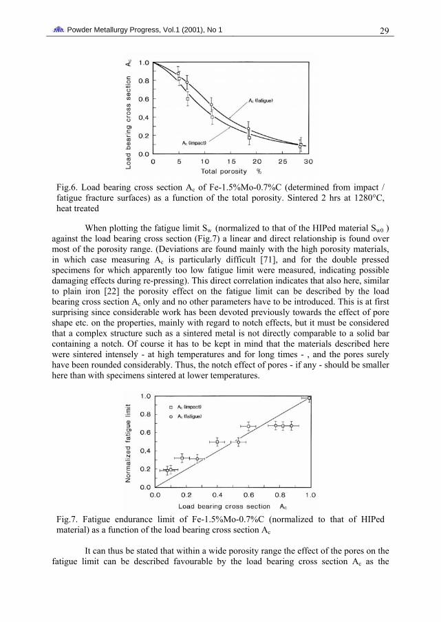
It is also evident that the fracture surfaces give reliable information about the pore connectivity. In the low porosity material the pores are mostly isolated, i.e. the sintering contacts are interconnected, while in the case of higher porosity the contacts are isolated due to interconnected porosity. As shown in [22] for plain iron, for a given porosity level, interconnected porosity results in lower Ac values than isolated porosity. The transition from isolated to interconnected pores - typically occurring in the porosity range 5 .. 20% - thus should result in a particularly pronounced decrease of Ac. This is confirmed by Fig.6 depicting Ac - obtained from impact and fatigue surfaces, respectively - as a function of the total porosity. The most pronounced decrease of Ac is found in the porosity range 5 ... 15%, which thus can be attributed to the change in pore morphology. At very low and very high porosity levels, changes in total porosity result in some change of the pore diameter and the sintering neck diameter, respectively, but the type of porosity is not changed and the impact on Ac is thus decidedly smaller.
a) Ptot = 6.2%
b) as Fig.5a, analyzed image
c) Ptot = 12.3% d) as Fig.5c, analyzed image Fig.5. Impact fracture surfaces (77K) of Fe-1.5%Mo-0.7%C of varying porosity. Sintered 2 hrs 1280°C, heat treated. Left: SEM fractograph; right: analyzed image; broken contacts shown white [76].
Powder Metallurgy Progress, Vol.1 (2001), No 1 29
Fig.6. Load bearing cross section Ac of Fe-1.5%Mo-0.7%C (determined from impact / fatigue fracture surfaces) as a function of the total porosity. Sintered 2 hrs at 1280°C, heat treated
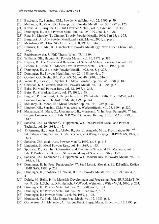
When plotting the fatigue limit Sw (normalized to that of the HIPed material Sw0 ) against the load bearing cross section (Fig.7) a linear and direct relationship is found over most of the porosity range. (Deviations are found mainly with the high porosity materials, in which case measuring Ac is particularly difficult [71], and for the double pressed specimens for which apparently too low fatigue limit were measured, indicating possible damaging effects during re-pressing). This direct correlation indicates that also here, similar to plain iron [22] the porosity effect on the fatigue limit can be described by the load bearing cross section Ac only and no other parameters have to be introduced. This is at first surprising since considerable work has been devoted previously towards the effect of pore shape etc. on the properties, mainly with regard to notch effects, but it must be considered that a complex structure such as a sintered metal is not directly comparable to a solid bar containing a notch. Of course it has to be kept in mind that the materials described here were sintered intensely - at high temperatures and for long times - , and the pores surely have been rounded considerably. Thus, the notch effect of pores - if any - should be smaller here than with specimens sintered at lower temperatures.
Fig.7. Fatigue endurance limit of Fe-1.5%Mo-0.7%C (normalized to that of HIPed material) as a function of the load bearing cross section Ac
It can thus be stated that within a wide porosity range the effect of the pores on the
fatigue limit can be described favourable by the load bearing cross section Ac as the

Powder Metallurgy Progress, Vol.1 (2001), No 1 30 relevant microstructural parameter. Most effective is also the pore connectivity, isolated pores resulting in higher Ac than interconnected ones and thus also in higher fatigue limits. For obtaining optimum fatigue behaviour, isolated porosity should thus be aimed at which is attained by compacting to reasonable density combined with sintering at high temperatures.
INFLUENCE OF THE SINTERING PARAMETERS With plain iron it has been found that the mechanical properties are affected by the
sintering parameters, too, in particular in the low porosity range [78]. This could reasonably be expected also for high strength Mo alloy steels since it had been shown previously that the monotonic – static and dynamic - properties of these steels can be significantly improved by sintering at higher temperatures [52, 66].
Therefore tests were carried out with specimens of identical green density but sintered differently. The HCF test specimens were produced as described in Chapter 3, compacting being done uniformly at 700 MPa, with a resulting green density of about 7.25 g.cm-3. The de-waxed compacts were vacuum sintered at temperatures between 1120 and 1280°C, in part also for different lengths of time. Fatigue specimens were produced by machining, and the heat treatment was done as described above by oil quenching and tempering at 400°C. Standard S-N curves were taken up to Nmax = 109.
Fig.8. S-N curves of PM steels Fe-1.5%Mo-0.7%C. Compacted 700 MPa, sintered 2 hrs at different temperatures, heat treated
Fig.9. Fatigue limit of differently sintered PM steels Fe-1.5%Mo-0.7%C (heat treated) as a function of the total porosity.
S-N curves of some differently sintered steels are given in Fig.8; the positive effect of high sintering temperatures is clearly recognised. In Fig.9 the fatigue endurance limit values obtained are shown, they are depicted as a function of the total porosity (as in Fig.7) to take into account also the density variations caused by different sintering parameters. It is evident that the sintering parameters, especially the temperature, strongly affect the fatigue endurance limit and that the effect is markedly more pronounced than in the case of plain iron [22]. The influence of Ts is in a similar range as is the total porosity - and thus the compacting parameters - , since a material with approximately 8% sintered at 1120°C exhibits roughly the same fatigue endurance limit as a steel sintered at 1280°C but having 17% porosity.
These results once more underline that especially with high strength steels, obtaining superior mechanical – in particular fatigue - behaviour necessitates not only high density - and thus double pressing or warm pressing [79] - but also sufficiently high sintering temperatures, temperature increase being more efficient than extension of the sintering time. While the dimensional change takes place mainly during the heating stage of

Powder Metallurgy Progress, Vol.1 (2001), No 1 31 the sintering process [80], the fatigue endurance strength is strongly affected also by processes occurring during prolonged isothermal sintering such as pore rounding and especially transformation from interconnected to isolated pores which beneficially affects the effective load bearing cross section.
Fig.10. Fatigue limit and load bearing cross section of Fe-1.5%Mo-0.7%C as a function of the sintering temperature. Compacted 700 MPa, sintering time 2 hrs
That also sintering and not only compaction exerts a pronounced influence on Ac
can be seen from Fig.10 in which the fatigue endurance limit and the load bearing cross section are plotted as a function of the sintering temperature. Also here the parallel trends of Ac and Sw are clearly discernible. Most noteworthy is the strong effect of sintering at temperatures >1250°C as compared e.g. to the temperature range 1120…1200°C which underlines the potential of compaction to high density combined with appropriate sintering.
MATRIX HOMOGENEITY In PM, in contrast to ingot metallurgy, microstructural homogeneity can be varied
over a wide range. It is possible to start from powder mixes, i.e. from a system in chemical inequilibrium, and to control the microstructural homogenization occuring through heterodiffusion during sintering by appropriately adjusting the sintering parameters. Fully homogeneous PM steels can be produced by using prealloyed, i.e. initially homogeneous, starting powders or by starting from powder mixes and then affording intense sintering. For Mo alloy steels it has been shown that the monotonic properties are significantly better if Mo is homogeneously distributed [52, 81], which in this case is attained by using prealloyed powders or by sintering compacts from mixed powders at sufficiently high temperatures.
The influence of the matrix homogeneity on HCF behaviour was studied by preparing Mo steel specimens either from the prealloyed powder Fe-1.5%Mo or from a mix of plain iron powder and elemental Mo. The mixes were compacted at 700 MPa and sintered in vacuum at 1200 and 1280°C, respectively, in case of the powder mix the former temperature resulting in solid state sintering and the latter one in formation of transient liquid phase that strongly enhances Mo homogenisation [66, 81, 82]. The microstructures thus obtained are given in Fig.11, and the different Mo distribution stands out clearly.

Powder Metallurgy Progress, Vol.1 (2001), No 1 32
a) prealloyed, sintered at 1200°C b) prealloyed, sintered at 1320°C
c) mixed, sintered at 1200°C d) mixed, sintered at 1320°C Fig.11. Metallographic sections of Fe-1.5%Mo-0.7%C, prepared from prealloyed /mixed powders, sintered at different temperatures
Fig.12. S-N curves of PM steel Fe-1.5%Mo-0.7%C prepared from prealloyed / mixed powders. Compacted at 700 MPa, sintered 2 hrs in vacuum, quenched and tempered
Fatigue test specimens were prepared and heat treated as described above, and HC
fatigue testing was done up to Nmax = 109 cycles. In Fig.12, the S-N curves are given for the 4 different materials. It can clearly beseen that for sintering at 1200°C, the steel from mixed powder is markedly inferior to that from prealloyed one while after sintering at 1280°C there is virtually no influence of the alloying technique. This can be attributed to the fact that solid state sintering at 1200°C results in very incomplete Mo homogenization while at 1280°C in the mixed system transient liquid phase is formed that strongly accelerates Mo distribution in the matrix [81], the differences in the Mo concentration within the material being virtually negligible.

Powder Metallurgy Progress, Vol.1 (2001), No 1 33
Therefore it can be concluded that at least for the Mo alloy steels tested here and for high cylce fatigue loading, a homogeneous microstructure seems to be better than a heterogeneous one, probably due to better utilization of the alloy element and to less probability of larger soft areas being present that act as crack initiation sites, as are the ferritic islands in sintered Distaloy grades [41].
FATIGUE ENDURANCE STRENGTH OF AS-SINTERED STEELS For the Mo alloy steels described here, it has been shown previously that the
mechanical properties can be influenced considerably by suitable heat treatment [32, 66]. The tensile strength can be increased from 700 ... 800 MPa in the as sintered state up to 1500 MPa without intolerable loss of ductility. This is probably due to the finer microstructure obtained through heat treatment which also was found to affect the fracture behaviour [73]. Therefore all tests described so far have been done with heat treated steels. On the other hand, heat treatment increases production cost and inevitably results in some distortion. Therefore, avoiding heat treatment by using the parts as sintered is attractive [83]).
In order to check this possibility, specimens were compacted at 700 MPa and sintered 2 hrs at 1280°C in vacuum. In part the specimens were machined and tested in the as-sintered state – the microstructure exhibiting relatively coarse upper bainite - , in part they were heat treated by the standard treatment given above, i.e. 860°C -> oil + 60 min at 400°C. (The microstructures are shown in Fig.1). These latter specimens had a hardness of approx. 420 HV30 (as-sintered hardness: about 210 HV30). The specimens were fatigue tested at 20 kHz up to 109 cycles; the S-N curves are shown in Fig.13.
Fig.13. S-N curves of Fe-1.5%Mo-0.7%C, Compacted at 700 MPa, sintered 2 hrs 1280°C, as sintered / heat treated
Evidently the fatigue endurance strength depends strongly also on the matrix
microstructure, and the difference between as sintered and heat treated materials is most pronounced at high loading cycle numbers. Quenched and tempered steels exhibit virtually a fatigue endurance limit, in contrast to the softer as-sintered ones. With the former material the slope of the S-N curve at N>107 is rather low, while for the as- sintered steels a decrease from 270 MPa to 190 MPa, i.e. about 30%, is observed in the range 107….109 loading cycles. Also the scatter of the values is markedly lower with the heat treated steels compared to the as sintered ones. Especially for engine parts such as connecting rods that have to reliably survive >108 loading cycles, heat treated steels thus seem to be preferable, at least if geometrical factors such as notches are not too dominant, see [14, 84].

Powder Metallurgy Progress, Vol.1 (2001), No 1 34
INFLUENCE OF SINGULAR DEFECTS IN THE MICROSTRUCTURE The role of singular defects on the mechanical properties is well known for
structural ceramics the static strength of which is usually controlled by the largest defect in the stressed volume. For metallic materials this behaviour is not as pronounced; metals are much more defect tolerant. However, as described above for high cycle fatigue loading, singularities such as inclusions and pores have a deleterious effect similar to that found in ceramics.
For powder metallurgy materials, also for sintered steels, the probability of singular defects being present in the structure is higher than in cast and wrought steels since powder technology on the one hand enables production of segregation-free structures but on the other hand is also incapable of removing defects through segregation or de-mixing processes. Foreign particles contained within the bulk powder, e.g. in a pressing tool, remain there and at least leave some imprint on the final structure. Furthermore, also metallurgical reactions such as formation of transient liquid phase result in secondary pores being generated during sintering [51].
In Fig.14, some crack initiating defects found in high strength Mo alloy steel are shown. These include slag inclusions (Fig.14a) but also voids generated through partial reduction of oxide particles (Fig.14b) and through formation of transient liquid phase (Fig.14c); of course also lumps of pressing lubricant would result in similar voids. Other characteristic defects are clusters of primary pores, caused by packing inhomogeneities of the powder particles, as shown e.g. in Fig.14d. Typically these defects have caused failure at very high loading cycle numbers, usually well above N = 107, and thus probably would not have been detected by standard fatigue testing procedures.
In order to assess the effect of such defects on the fatigue endurance of the sintered materials, using an appropriately modified Kitagawa-Takahashi diagram has been proposed [57]. This diagram is based on a fracture mechanics concept and enables describing the relationship between the maximum endurable stress and the size of a defect if defects are regarded as cracks [85]. The diagram indicates the range of maximum allowable defect size (up to which no fracture starts from this defect) as a function of the stress amplitude. This area is confined by the fatigue limit of the defect-free material and the threshold stress intensity factor ΔKth which both have to be measured experimentally (depending on the conditions [86], in some cases the effective threshold ΔKth,eff has to be substituted for ΔKth). Furthermore, for every material a critical defect size can be defined below which the defects are not effective but above which the fatigue endurance strength Sw depends on the size a of the largest defect in the stressed volume as given by Eq.1. It must however be stated that such a Kitagawa diagram is valid only for a given loading mode (i.e. a given R and Nmax); at different loadings also different results may be obtained, and the critical defect size may be markedly shifted.
Sw = ΔKtheff / F.(π.a)0.5 (1)
In order to check the sensitivity of the sintered steels tested here, the results described in Chapter 4 were used, and with the same materials with widely varying porosity also the threshold stress intensity factors ΔKth and ΔKth,eff were determined (see Chapter 3). In Fig.15 both ΔKth and ΔKth,eff are plotted as a function of the total porosity, and if comparing this diagram with Fig.6 it is evident that Sw is affected considerably more by the porosity than is the threshold stress intensity factor (which is in agreement with the lower notch sensitivity of sintered steels as shown in [6, 37]). The consequence of this behaviour can be seen in Fig.16, depicting a Kitagawa diagram for materials of different porosity:

Powder Metallurgy Progress, Vol.1 (2001), No 1 35 with decreasing total porosity - and thus increasing fatigue limit - the intersection between the horizontal line (Sw) and the sloped line (ΔKth) is shifted to smaller defect sizes, i.e. in fact the materials are the more sensitive to singular defects the better their basic performance is.
Fig.14. Fatigue crack initiating singular defects in sintered steel Fe-1.5%Mo-0.7%C
Fig.15. Threshold stress intensity factors ΔKth and ΔKtheff of Fe-1.5%Mo-0.7%C as a function of the total porosity. Sintered 2 hrs at1280°C, heat treated
Fig.16. Kitagawa-Takahashi diagram (plotted from Sw and ΔKtheff) for Fe-1.5%Mo-0.7%C of varying density, heat treated

Powder Metallurgy Progress, Vol.1 (2001), No 1 36
In order to check the applicability of the Kitagawa concept for real defects in sintered steels, Mo alloy steels containing defects of a given size were produced from elemental powders mixes using 5 different Mo powder fractions varying from <25 to 180 μm. As described previously [51], transient liquid phase during sintering results in formation of secondary pores with approximately double the size of the original Mo particles [87]. Therefore, a wide variation of defect size (i.e. secondary pore size) - <50 up to approx. 400 μm - could be obtained by varying the Mo powder fraction from <25 µm to about 200 µm.
Fig.17. Kitagawa-Takahashi diagram for Fe-1.5%Mo-0.7%C containing secondary pores (diamond symbols) as compared to that predicted from Sw and ΔKtheff (solid lines)
The fatigue endurance strength was determined for the 5 materials. In Fig.17, the respective experimentally obtained Kitagawa diagram is shown, containing the fatigue limit plotted against the respective secondary pore size (diamond symbols), as well as that calculated from Sw and ΔKtheff (solid lines). Here it can be seen that compared to the graph calculated from the threshold stress intensity factor the experimentally determined values are found at significantly smaller defect size levels, the ratio between calculated and experimentally determined defect sizes for every material being in the range of 4. This means that smaller defects theoretically estimated to be subcritical in fact cause fatigue failure, i.e. in fact they are supercritical.
Fig.18. Crack initiating secondary pore cluster in Fe-1.5%Mo-0.7%C (elemental powder mix, Mo fraction 42-63 µm)

Powder Metallurgy Progress, Vol.1 (2001), No 1 37
The reason for this surprising difference could be found through fractographic investigations. It was shown that around each crack-initiating singular defect a very smooth circular area can be observed that is about double the size of the defect itself. It can be concluded that the effective defect size is given by the extent of the stress field surrounding the individual defect [48, 88]. Secondly, each crack initiation site in these specimens was found to consist not only of a single defect but that in all cases the crack had started from a group of two neighbouring secondary pores (Fig.18), and the radius of the stress field around the defect clusters was about twice the geometrical radius of the cluster. I.e. a crack-initiating defect consisting of two closely adjacent pores has an effective radius of about 4 times the radius of the individual defect, which explains the difference observed here. If not the geometrical secondary pore radius (calculated from the Mo fraction used) but the effective radius of a cluster consisting of two neighbouring pores is plotted in the Kitagawa diagram, there is agreement between the calculated and the experimentally determined values.
In practice this means that not only the size of each individual singular defect has to be kept to a minimum (if it cannot be completely avoided) but also the number of these defects has to be minimized, in order to lower the probability of two adjacent subcritical defects forming a single supercritical one.
CONCLUSIONS • For studying the high cycle fatigue behaviour of sintered steels, Mo alloy steels
prepared from prealloyed powder have shown to be a well suited model material since the influence of microstructural inhomogeneities in the matrix can be safely excluded. They also offer considerable potential for fatigue loaded PM precision parts.
• Ultrasonic resonance testing is a promising tool for investigating the behaviour of sintered steels at loading cycle numbers up to 109 cycles which are quite realistic e.g. for automotive engine components.
• In order to obtain optimum fatigue endurance strength at high loading cycle numbers, sintered steels should be compacted to high density - warm compaction probably being a promising way - and sintered at sufficiently high temperatures. The effect of sintering is particularly pronounced at low to medium porosity levels.
• As a microstructural parameter the load bearing cross section Ac is highly relevant for the fatigue endurance strength although it is more difficult to determine than e.g. the metallographically determined pore parameters.
• In Mo alloy steels, a homogeneous Mo distribution attained e.g. by using prealloyed powders or by appropriate sintering techniques results in better fatigue endurance strength than does a inhomogeneous microstructure.
• Heat treatment can be beneficial especially at loading cycle numbers >107, at least with unnotched specimens; in the as-sintered state a true fatigue limit apparently does not exist.
• Singular defects such as inclusions, secondary pores, or pore clusters adversely affect the fatigue behaviour especially at high loading cycles if their size exceeds a given limit.
• The critical defect size is the lower the higher the basic performance of the material is, i.e. better PM steels are more sensitive to singular defects in the microstructure. This is due to the fact that the fatigue endurance strength is lowered by the porosity much more than is the threshold stress intensity factor.

Powder Metallurgy Progress, Vol.1 (2001), No 1 38
• Carefully optimised manufacturing parameters combined with clean starting materials and processing are the keys for manufacturing of fatigue loaded precision parts.
Appendix: List of symbols: Ptot … total porosity σ … cyclic stress amplitude Sw … fatigue endurance strength ΔK … cyclic stress intensity factor ΔKth … threshold stress intensity factor ΔKtheff … effective threshold stress intensity factor Kt … notch factor E … Young’s modulus a … defect radius N … loading cycle number R … stress ratio F … geometrical correction factor
Acknowledgement This work was financially supported by the Austrian Fonds zur Förderung der
wissenschaftlichen Forschung (Projects P8262 and P11014). Furthermore, the experimental assistance by Mr. J. Preitfellner and Mr. D. Spoljaric as well of MIBA Sintermetall AG, Vorchdorf, is gratefully acknowledged.
REFERENCES [1] Šalak, A.: Ferrous Powder Metallurgy. Cambridge : Cambridge Int.Sci.Publ., 1995 [2] Pohl, D.: Powder Metall. Int., vol. 16, 1984, no. 1, p. 19. [3] Hall, DW., Mocarski, S.: Int.J.Powder Metall., vol. 21, 1985, no. 2, p. 79. [4] Mocarski, S., Hall, DW.: Int.J.Powder Metall., vol 23, 1987, no. 2, p. 109. [5] Baum, U., Hock, S., Kolzarek, F. In: Pulvermet. in Wiss. und Praxis, Bd. 10. Ed.
H.Kolaska, Hagen, 1994, p. 84. [6] Esper, FJ., Sonsino, CM.: Fatigue Design for PM Components. Shrewsbury : EPMA,
1994. [7] Sonsino, CM.: Powder Metall.Int., vol. 16, 1984, p. 73. [8] Piotrowski, A., Biallas, G. In: Proc. PM’98, vol.4. Granada, p. 362. [9] Karlsson, B., Bertilsson, I.: Scand.J.Metallurgy, vol. 11, 1982, p. 267.
[10] Weiss, B., Danninger, H. In: Encyclopaedia of Materials: Science and Technology. Eds. K.H.J.Buschow, R.W.Cahn, M.C.Flemings, B.Ilschner, E.J.Kramer, S.Mahajan. Elsevier, in press.
[11] Hadrboletz, A., Weiss, B.: Int.Mater.Reviews, vol. 42, 1997, no. 1. [12] Vedula, K., Heckel, RW.: Modern Dev. in Powder Metall., vol. 12, 1981, p. 759. [13] Straffelini, G., Fontanari, V., Molinari, A.: Mat.Sci.and Engrg., vol. A260, 1999, p.
197. [14] Klumpp, S.: PhD Thesis. Karlsruhe, 1992. [15] Piotrowski, A., Eifler, D.: Adv. Powder Metall.and Partic.Mater., vol. 6, 1992, p. 363. [16] Bertilsson, I., Karlsson, B.: Powder Metall.Int., vol. 14, 1982, p. 13. [17] Lindstedt, U., Karlsson, B.: Proc. PM’94. 1994 Powder Metall.World Congress, Paris,
SF2M ed., Editions de Physique, Les Ulis, 1994. [18] Melišová, D., Khatibi, G., Weiss, B., Danninger, H. In: Proc. 10th Int. Symp.
Metallography ‘98, Stará Lesná. Košice : TU, 1998, p. 426.
Powder Metallurgy Progress, Vol.1 (2001), No 1 39
[19] Buxbaum, O., Sonsino, CM.: Powder Metall.Int., vol. 22, 1990, p. 59. [20] Mellanby, IJ., Moon, JR., Leheup, ER.: Powder Metall., vol. 30, 1987, p. 125. [21] Kravic, AF., Pasquine, OL.: Int.J.Powder Metall., vol. 5, 1969, no. 1, p. 45. [22] Danninger, H., et al.: Powder Metall.Int., vol. 25, 1993, no. 4, p. 170. [23] Rutz, H., Murphy, T., Cimino, T.: Adv.Powder Metall., 1996, Part 13, p. 375. [24] Bergmark, A.: Adv.Powder Metall.and Partic.Mater., 2001, in press. [25] McAdam, GD.: J.Iron Steel Inst., vol. 168, 1951, p. 346. [26] Hausner, HH., Mal, K.: Handbook of Powder Metallurgy. New York : Chem. Publ.,
1982. [27] Radziwanowska, J.: PhD Thesis. Wien : TU, 1989. [28] Williams, SH., Haynes, R.: Powder Metall., vol. 16, 1973, p. 387. [29] Haynes, R.: The Mechanical Behaviour of Sintered Metals. London : Freund, 1981 [30] Ledoux, L., Prioul, C.: Modern Dev. in Powder Metall., vol. 21, 1988, p. 41. [31] Danninger, H., et al.: Adv.Powder Metall., 1992, no. 5, p. 227. [32] Danninger, H.: Powder Metall.Int., vol. 20, 1988, no. 4, p. 7. [33] Goetzel, CG., Seelig, RP.: Proc.ASTM, vol. 40, 1940, p. 746. [34] Weiss, B., Stickler, R., Sychra, H.: Metal Powder Rep., vol. 45, 1990, p. 187. [35] Christian, KD, German, RM: Int.J.Powder Metall., vol. 31, 1995, p. 51. [36] Beiss, P.: Metal Powder Rep., vol. 42, 1987, p. 243. [37] Beiss, P.: Z.Werkstofftech., vol. 17, 1986, p. 89. [38] Engdahl, P., Lindqvist, B., Tengzelius, J. In: PM into the 1990s. Proc. PM'90, vol.2,
London. London : The Inst. of Metals, 1990, p. 144. [39] Mellanby, IJ., Moon, JR.: Metal Powder Rep., vol. 44, 1989, p. 432. [40] Lindner, KH., Sonsino, CM.: Mat.-wiss. u. Werkstofftech., vol. 25, 1994, p. 227. [41] Matsunaga, H., Mars, O., Johannesson, B., Murakami, Y. In: Proc. Fatigue99. 7th Int.
Fatigue Congress, vol. 3. Eds. X.R.Wu, Z.G.Wang. Beijing : HEP/EMAS, 1999, p. 1817.
[42] Sonsino, CM., Schlieper, G., Huppmann, WJ.: Int.J.Powder Metall.and Powder Technol., vol. 20, 1984, p. 45.
[43] D’Armans, H., Llanes, L., Altaba, B., Bas, J., Anglada, M. In: Proc. Fatigue 99. 7th Int. Fatigue Congress, vol. 3. Eds. X.R.Wu, Z.G.Wang. Beijing : HEP/EMAS, 1999, p. 1823.
[44] Sonsino, CM., et al.: Adv. Powder Metall., 1992, no. 5, p. 115. [45] Lindquist, B.: Metal Powder Rep., vol. 44, 1989, p. 443. [46] Spoljaric, D., et al. In: Deformation and Fracture in Structural PM Materials, vol. 1.
Eds. Ľ.Parilák et al. Košice : Slovak Academy of Sciences, 1996, p. 159. [47] Sonsino, CM., Schlieper, G., Huppmann, WJ.: Modern Dev. in Powder Metall., vol. 16,
1985, p. 33. [48] Danninger, H. In: Proc. Fractography 97, Stará Lesná, Slovakia. Ed. Ľ.Parilák. Košice
: IMR SAS, 1997, p. 252. [49] Danninger, H., Spoljaric, D., Weiss, B.: Int.J.Powder Metall., vol. 33, 1997, no. 4, p.
43. [50] Dalgic, M., Beiss, P. In: Materials Development and Processing. Proc. EUROMAT‘99,
vol. 8. Eds. L.Schultz, D.M.Herlach, J.V.Wood. Weinheim : Wiley-VCH, 2000, p. 203. [51] Danninger, H.: Powder Metall.Int., vol. 20, 1988, no. 1, p. 21. [52] Danninger, H.: Powder Metall.Int., vol. 24, 1992, no. 2, p. 73. [53] Danninger, H.: Powder Metall., vol. 30, 1987, p. 103. [54] Murakami, Y., Endo, M.: Engrg.Fract.Mech., vol. 17, 1983, p. 1. [55] Gustavsson, AI., Melander, A.: Fatigue Fract. Engrg. Mater. Struct., vol. 15, 1992, p.

Powder Metallurgy Progress, Vol.1 (2001), No 1 40
881. [56] Betz, W., Track, W.: Powder Metall.Int., vol. 13, 1981, p. 195. [57] Weiss, B., Stickler, R.: Modern Dev. in Powder Metall., vol. 21, 1988, p. 3. [58] Stickler, R., Weiss, B. In: Ultrasonic Fatigue. Eds. J.Wells, et al. TMS AIME, 1982, p.
135. [59] Spoljaric, D., Danninger, H., Weiss, B., Chen, DL., Ratzi, R. In: Deformation and
Fracture in Structural PM Materials, vol.1. Eds. Ľ.Parilák, et al. Košice: Slovak Academy of Sciences, 1996, p. 147.
[60] Newman, JC., Raju, S.: Engrg.Fract.Mech., vol. 15, 1981, p. 185. [61] Hadrboletz, A., Weiss, B., Stickler, R. In: Handbook of Fatigue Crack Propagation in
Metallic Structures. Ed. A.Carpinteri. Elsevier, 1994, p. 847. [62] Elber, W.: Eng.Fract.Mech., 1970, no. 2, p. 37. [63] Chen DL., et al.: J.Mater.Sci.Technol., vol. 13, 1997, p. 1. [64] Eudier, M.: Powder Metall., 1962, p. 278. [65] Šalak, A., et al.: Powder Metall.Int., vol. 6, 1974, p. 128. [66] Danninger. H., et al.: Adv. Powder Metall., 1996, Part 13, p. 177. [67] Buxbaum, O., Sonsino, CM. In: Materials by Powder Technology. Ed. F.Aldinger.
Oberursel : DGM, 1992, p. 551. [68] Koch, KH.: Personal communication [69] Yamada, K., Kim, MG., Kunio, T. In: The Behaviour of Short Fatigue Cracks. Eds.
K.J.Miller, E.R.de los Rios. London : Mechanical Engineering Publ., 1986, p. 261. [70] Sychra, H., Weiss, B., Stickler, R. In: Proc. 12th Int. Plansee-Sem, vol.2. Eds.
H.Bildstein, H.M.Ortner. Reutte : Metallwerk Plansee, 1989, p. 835. [71] Danninger, H., et al.: Prakt.Metallogr., vol. 31, 1994, p. 56. [72] Zapf, G. In: Handbuch der Fertigungstechnik, Bd. 1. Ed. G.Spur. München-Wien :
C.Hanser, 1981. [73] Danninger, H., et al.: Z.Metallkunde, vol. 89, 1998, p. 135. [74] Simchi, A., Danninger, H., Gierl, C.: Powder Metall., vol. 44, 2001, p. 148. [75] Šlesár, M., et al.: Sci.Sintering, vol. 19, 1987, p. 17. [76] Šlesár, M., Dudrová, E., Rudnayová, E.: Powder Metall.Int., vol. 24, 1992, no. 4, p.
232. [77] Danninger, H., Sonntag, U., Kuhnert, B., Ratzi, R.: to be published [78] Danninger, H., Zengin, OZ., Drozda, M.: Metal Powder Rep., vol. 41, 1986, no. 11, p.
833. [79] Engström, U. In: Proc. PM’94. 1994 Powder Metallurgy World Congress, Paris, vol.1.
SF2M ed., Editions de Physique, Les Ulis, 1994, p. 57. [80] Schatt, W.: Sintervorgänge. Düsseldorf : VDI-Verlag, 1993. [81] Danninger, H.: Powder Metall.Int., vol. 24, 1992, no. 3, p. 163. [82] Danninger, H., Kara, T.: Powder Metall.Int., vol. 20, 1988, no. 6, p. 9. [83] Saito, T., Obayashi, M.: Modern Dev. in Powder Metall., vol. 21, 1988, p. 197. [84] Lindner, KH., Sonsino, CM. In: Proc. PM’94. 1994 Powder Metallurgy World
Congress, Paris, vol.2. SF2M ed., Editions de Physique, Les Ulis, 1994, p. 819. [85] Kitagawa, H., Takahashi, S. In: Proc. 2nd. Int. Conf. Mech. Behaviour of Mater. Metals
Park OH : ASM, 1976, p. 627. [86] Chen, DL.: PhD Thesis. University of Vienna, 1993. [87] Spoljaric, D., et al. In: Proc. PM’94. 1994 Powder Metallurgy World Congress, Paris,
vol.2. SF2M ed., Editions de Physique, Les Ulis, 1994, p. 827. [88] Weiss, B., et al. In: Short Fatigue Cracks, ESIS Publication 13. Eds. K.J.Miller, et al.
1992, p. 423.