UG64 - CapSense Demo for iCEblink40 Evaluation Kits User’s Guide
8
September 2012 UG64_01.0 CapSense Demo for iCEblink40 Evaluation Kits User’s Guide
Transcript of UG64 - CapSense Demo for iCEblink40 Evaluation Kits User’s Guide

September 2012UG64_01.0
CapSense Demo for iCEblink40 Evaluation Kits
User’s Guide
2
CapSense Demo foriCEblink40 Evaluation Kits
Introduction This document provides technical information and instructions for using the iCE40™ CapSense Demo. This demo is based on the iCEblink40™-LP1K and iCEblink40-HX1K Evaluation Kits. Functionally, the two kits are identical, except one is mounted with the low power LP series device (iCE40LP1K-QN84) and the other with the high perfor-mance HX series device (iCE40HX1K-VQ100). This user’s guide is common for both kits as the HDL source code is the same.
Software requirements for running the demo:
• iCEcube2™ design software
Hardware requirements for running the demo:
• iCEblink40-LP1K or iCEblink40-HX1K Evaluation Kit
• USB cable (included with the kit)
• PC (not provided)
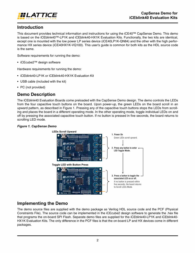
Demo DescriptionThe iCEblink40 Evaluation Boards come preloaded with the CapSense Demo design. The demo controls the LEDs from the four capacitive touch buttons on the board. Upon power-up, the green LEDs on the board scroll in an upward pattern, as described in Figure 1. Pressing any of the capacitive touch buttons stops the LEDs from scroll-ing and places the board in a different operating mode. In the other operating mode, toggle individual LEDs on and off by pressing the associated capacitive touch button. If no button is pressed in five seconds, the board returns to scrolling LED mode.
Figure 1. CapSense Demo
LEDs Scroll Upward
Toggle LED with Button Press
1. Power On Green LEDs scroll upward.
3. Press a button to toggle the associated LED on or off. If no button is pressed within five seconds, the board returns to Scroll LEDs Mode.
2. Press any button to enter LED Toggle Mode.
Implementing the DemoThe demo source files are supplied with the demo package as Verilog HDL source code and the PCF (Physical Constraints File). The source code can be implemented in the iCEcube2 design software to generate the .hex file that programs the on-board SPI Flash. Separate demo files are supplied for the iCEblink40-LP1K and iCEblink40-HX1K Evaluation Kits. The only difference in the PCF files is that the on-board LP and HX devices come in different packages.

3
CapSense Demo foriCEblink40 Evaluation Kits
Demo Source CodeiCEblink40-LP1K Evaluation KitThe iCEblink40-LP1K demo source code contains the following:
• Demo folder name: ICE-LP-CAPSENSE-010
• iCEblink40-LP1k_preloaded_design_verilog.v located in <Project Directory>ICE-LP-CAPSENSE-010\Source
• iCEblink40-LP1k_pin_constraints_file.pcf located in <Project Directory>ICE-LP-CAPSENSE-010\Source
• iceblink40_lp1k_demo_bitmap.hex located in <Project Directory>ICE-LP-CAPSENSE-010\Bistreams
iCEblink40-HX1K Evaluation KitThe iCEblink40-HX1K demo source contains the following:
• Demo folder name: ICE-HX-CAPSENSE-010
• iCEblink40-hx1k_preloaded_design_verilog.v located in <Project Directory>ICE-HX-CAPSENSE-010\Source
• iCEblink40-hx1k_pin_constraints_file.pcf located in <Project Directory>ICE-HX-CAPSENSE-010\Source
• iCEblink40-hx1k_precompiled_bitstream.hex <Project Directory>ICE-HX-CAPSENSE-010\Bitstreams
Procedure 1: Running the Pre-existing ProjectThis procedure allows you to open the pre-existing iCEcube2 demo project and re-implement it.
1. Open the iCEcube2 design software.
2. Select File > Open Project.
3. Browse to the path <Project Directory>ICE-LP-CAPSENSE-010\Target.
4. Select Target_sbt.project.
5. Click Open. The Project Navigator will open with the required files and device selection, as shown in Figure 5.
6. Double-click the Launch Synthesis tool. The Synplify Pro synthesis tool will open.
7. Click Run to synthesize the design (see Figure 6).
8. Exit the Synplify Pro synthesis tool and return to the iCEcube2 software. A green check mark will appear next to the Launch Synthesis tool.
9. Double-click Run-all and observe that the check mark appears on all processes up to “Generate Bitstream”.
10. See “Programming the iCEblink40 Evaluation Board” on page 7 for instructions on programming the device.
Procedure 2: Creating the Project with the Source FilesThe procedure below references the iCEblink40-LP1K board source files in building the project. The same proce-dure is valid for implementing the source files of the iCEblink40-HX1K Evaluation Kit.
1. Create a new folder and copy iCEblink40-LP1k_preloaded_design_verilog.v and iCEblink40-LP1k_pin_constraints_file.pcf (or iCEblink40-hx1k_preloaded_design_verilog.v and iCEblink40-hx1k_pin_constraints_file.pcf) into the folder.
2. Open the iCEcube2 design software.
4
CapSense Demo foriCEblink40 Evaluation Kits
Figure 2. iCEcube2 Design Software
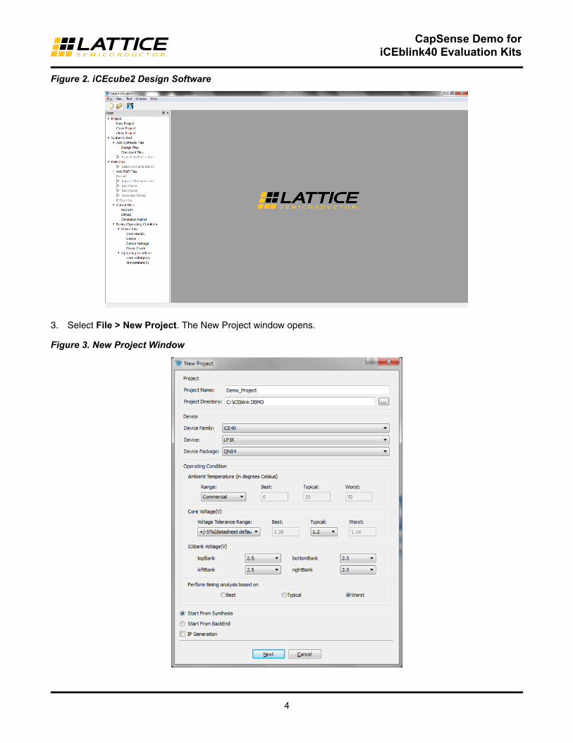
3. Select File > New Project. The New Project window opens.
Figure 3. New Project Window

5
CapSense Demo foriCEblink40 Evaluation Kits
4. Browse to the folder and provide a name for the project.
5. Select LP1K and QN84 as the Device and Device Package as shown in Figure 3 (select HX1K and VQ100 if you are using the iCEblink40-HX1K Evaluation Board).
6. Click Next and the Add Files dialog box will open. Select the existing Verilog HDL and PCF files by clicking >> to select them, as shown in Figure 4.
Figure 4. Add Files
7. Click Finish.
8. The project will open with the selected files, as shown in Figure 5.
Figure 5. iCEcube2 Project

6
CapSense Demo foriCEblink40 Evaluation Kits
9. Double-click the Launch Synthesis tool. The Synplify Pro synthesis tool will open.
10. Click Run to synthesize the design.
11. Exit the Synplify Pro synthesis tool and return to the iCEcube2 software. A green check mark will appear next to the Launch Synthesis tool.
Figure 6. Design Synthesis in Synplify Pro
12. In the iCEcube2 software console, double-click Run All. This will implement the design and generate the device configuration/programming file. A green check mark will appear next to the implementation options.

7
CapSense Demo foriCEblink40 Evaluation Kits
Figure 7. Fully Implemented Design
13. The on-board SPI Flash which configures the iCE40 device is now ready to be programmed. See the Program-ming the iCEblink40 Board section below for instructions on programming the SPI Flash with the newly-created programming file.
Programming the iCEblink40 Evaluation BoardThe iCEblink40 Evaluation Boards include on-board USB-based programming support. Ensure that the Adept USB programming software is installed with the iCEcube2 design software. Figure 8 shows the command sequence for programming the SPI Flash PROM on the iCEblink40 Evaluation Board using the iCEcube2 software.
Figure 8. Programming the iCEblink40 Evaluation Board

8
CapSense Demo foriCEblink40 Evaluation Kits
1. Connect the iCEblink40 Evaluation Board to the PC’s USB port through the USB cable provided.
2. Select Tool > Programmer from the iCEcube2 menu bar.
3. Click the drop-down button ( ) under Programming Hardware.
4. Select iCEblink40.
5. The bitstream file should already be set appropriately based on the iCEcube2 project settings. If not, click Image Files Settings to select the configuration bitstream file. Alternatively, the bitstream hex file is also located in the Biststreams folder of the Demo directory
6. Click Execute to program the iCEblink40 Evaluation Board.
7. Check for the “programmer succeed” message.
If all is working correctly, the power-on LED and the configuration done LED will both turn off momentarily as the iCEcube2 software programs the on-board SPI Flash PROM. After programming is complete, both LEDs should light up again and the iCE40 FPGA will execute the new configuration image, which is the CapSense demo as described in earlier sections.
References • EB73, iCEblink40-HX1K Evaluation Kit User’s Guide
• EB75, iCEblink40-LP1K Evaluation Kit User’s Guide
Technical Support AssistanceHotline: 1-800-LATTICE (North America)
+1-503-268-8001 (Outside North America)
e-mail: [email protected]
Internet: www.latticesemi.com
Revision HistoryDate Version Change Summary
September 2012 01.0 Initial release.
© 2012 Lattice Semiconductor Corp. All Lattice trademarks, registered trademarks, patents, and disclaimers are as listed at www.latticesemi.com/legal. All other brand or product names are trademarks or registered trademarks of their respective holders. The specifications and information herein are subject to change without notice.