UCSD, Columbia U., LLNL, ORNL, PPPL 22 The NCSX Team UCSD, Columbia U., LLNL, ORNL, PPPL in...
13
Physics Considerations in the Design of NCSX G. H. Neilson, for the NCSX Team Princeton Plasma Physics Laboratory Oak Ridge National Laboratory Lawrence Livermore National Laboratory Univ. of California at San Diego 19th IAEA Fusion Energy Conference Lyon, France 14-19 October 2002
Transcript of UCSD, Columbia U., LLNL, ORNL, PPPL 22 The NCSX Team UCSD, Columbia U., LLNL, ORNL, PPPL in...
Physics Considerations in theDesign of NCSX
G. H. Neilson,
for the NCSX Team
Princeton Plasma Physics Laboratory
Oak Ridge National Laboratory
Lawrence Livermore National Laboratory
Univ. of California at San Diego
19th IAEA Fusion Energy ConferenceLyon, France
14-19 October 2002

2
The NCSX Team
UCSD, Columbia U., LLNL, ORNL, PPPL
in collaboration withAuburn, NYU, SNL-A, Texas-Austin, Wisconsin
Australia, Austria, Germany, Japan , Russia, Spain, Switzerland, Ukraine
R. Benson, ORNLL. Berry, ORNLA. Boozer, Columbia U.A. Brooks, PPPLT. Brown, PPPLJ. Chrzanowski, PPPLM. Cole, ORNLF. Dahlgren. PPPLL. Dudek, PPPLH. M. Fan, PPPLM. Fenstermacher, LLNLE. Fredrickson, PPPLG. Fu, PPPLA. Georgievskiy, PPPL
R. J. Goldston, PPPLP. Goranson, ORNLA. Grossman, UCSDP. Hampton, PPPLR. Hatcher, PPPLR. Hawryluk, PPPLP. Heitzenroeder, PPPLS. Hirshman, ORNLS. Hudson, PPPLD. Johnson, PPPLC. Jun, PPPLA. Koniges, LLNLL.-P. Ku, PPPLH. Kugel, PPPL
E. Lazarus, ORNLJ. Levine, PPPLJ. Lyon, ORNLR. Majeski, PPPLJ. Malsbury, PPPLD. Mikkelsen, PPPLP. Mioduszewski, ORNLD. Monticello, PPPLH. Mynick, PPPLG. Neilson, PPPLB. Nelson, ORNLG. Oliaro, PPPLN. Pomphrey, PPPLS. Ramakrishnan, PPPL
M. Redi, PPPLW. Reiersen, PPPLA. Reiman, PPPLP. Rutherford, PPPLJ. Schmidt, PPPLR. Simmons, PPPLB. Stratton, PPPLR. Strykowsky, PPPLD. Spong, ORNLD. Strickler, ORNLH. Takahashi, PPPLR. White, PPPLD. Williamson, ORNLM. Zarnstorff, PPPL
3
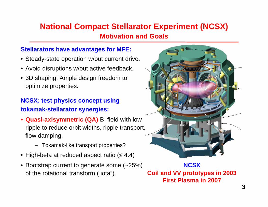
National Compact Stellarator Experiment (NCSX)Motivation and Goals
Stellarators have advantages for MFE:
• Steady-state operation w/out current drive.
• Avoid disruptions w/out active feedback.
• 3D shaping: Ample design freedom tooptimize properties.
NCSX: test physics concept usingtokamak-stellarator synergies:
• Quasi-axisymmetric (QA) B–field with lowripple to reduce orbit widths, ripple transport,flow damping.
– Tokamak-like transport properties?
• High-beta at reduced aspect ratio (≤ 4.4)
• Bootstrap current to generate some (~25%)of the rotational transform (“iota”).
NCSXCoil and VV prototypes in 2003
First Plasma in 2007

4
Key Physics Considerations in the NCSX Design
• Optimize for a β=4% QA stellarator target equilibrium.
– Test of quasi-symmetry in HSX: J. N. Talmadge, et al., EX/P3-22.
• Ability to access target state starting from vacuum.
• Flexibility to test physics, accommodate profile variations.
• Space for divertors.
5
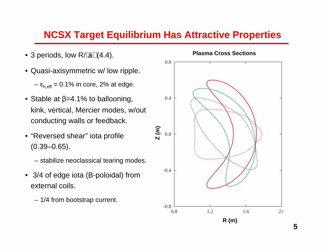
NCSX Target Equilibrium Has Attractive Properties
• 3 periods, low R/⟨a⟩ (4.4).
• Quasi-axisymmetric w/ low ripple.
– εh,eff = 0.1% in core, 2% at edge.
• Stable at β=4.1% to ballooning,
kink, vertical, Mercier modes, w/outconducting walls or feedback.
• “Reversed shear” iota profile(0.39–0.65).
– stabilize neoclassical tearing modes.
• 3/4 of edge iota (B-poloidal) fromexternal coils.
– 1/4 from bootstrap current.
Plasma Cross Sections
-0.8�
-0.4�
0.0�
0.4�
0.8�
0.8� 1.2� 1.6� 2.0
R (m)
Z (
m)

6
Coil Design Satisfies Physics and Engineering Criteria
• NCSX design uses 18 modular coils
(3 shapes)
– Also TF, PF, and helical trim coils.
• Free-boundary VMEC-based methodwas developed to optimize coils for low-R/⟨a⟩, current-carrying stellarators.
– D. J. Strickler, et al., FT/P2-06 (Fri. p.m.)
• Required properties are realized:
– Free-boundary equilibrium with therequired physics properties (R/⟨a⟩, QA,stability at β = 4%, iota profile).
– Engineering feasibility metrics: coil-coil
spacing, min. bend radius, tangential NBIaccess, coil-plasma spacing.
– Good magnetic surfaces.

7
Coil Design Produces Good Surfaces at High ββββ
• Free-boundary PIESequilibrium for β = 4%.
• Multi-filament coils.
Sum of effective islandwidths is <1%.
• Coil geometry adjusted to “heal” islands (measured with PIES code) whilepreserving physics and engineering properties.
– S, R. Hudson et al, next talk.
• Corrections for neoclassical and finite χ⊥ /χ|| effects (not included in PIEScalculation) reduce effective island width by factor 2-3.
Also, good surfaces in a range of vacuum configurations.
VMEC plasma boundarywith unhealed coils
First wall boundary

8
A Wide Range of Plasma Conditions Is Accessible
Machine Parameters• R = 1.4 m• B = 1.2 - 2.0T• PNBI ≤ 6 MW (tangential access, 0.3 s pulse)
• PRF ≤ 6 MW (high-field-side launch)
ββββ = 4% at B = 1.2 T, P = 6 MW (assuming ττττE = 2.9 ×××× ISS95 ≈≈≈≈ L-mode)• ne = 6 × 10¹⁹ m-3
• Ti(0) = 1.8 keV• νi* = 0.25
Many regimes available to test physics• Low νi* (~0.1), high Ti (≤2.5 keV) with B → 2 T.• High ne (≤ 1.6 × 10²⁰ m-3) Sudo limit at B = 1.2 T.
• Long pulse (≤ 1.7 s) with heating upgrades.

9
Profile Evolution: Vacuum to High-Beta
New method uses TRANSP code to simulate time evolution of profilesin equivalent tokamak configuration.• External iota simulated as externally driven current.• Ohmic startup: Vloop ≈ 1 V, clamped after initial 1.5 MA/s current rise.
• 6 MW NBI: balanced to control iota perturbation from NBCD, modulated tocontrol pressure.
• Assumed empirical τE = min(neo-Alcator, L-mode)Reaches all-bootstrap target state with ββββ ≈≈≈≈ 4% after 0.3 s of heating.
0.1 0.2 0.3 0.4 0
100
(
kA )
Ip
IBS
0.1 0.2 0.3 0.4TIME (SECONDS)
0
1
2
3
4
5
βΤ
%
β
TIME (SECONDS)
10
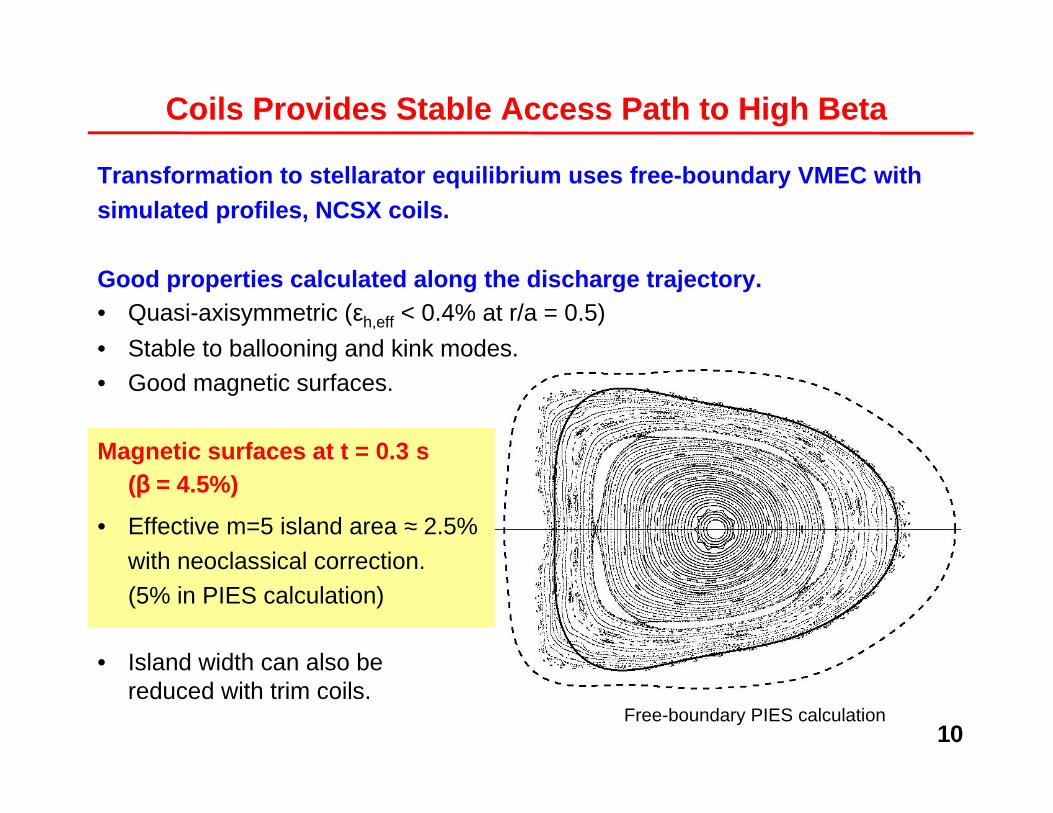
Coils Provides Stable Access Path to High Beta
Transformation to stellarator equilibrium uses free-boundary VMEC withsimulated profiles, NCSX coils.
Good properties calculated along the discharge trajectory.• Quasi-axisymmetric (εh,eff < 0.4% at r/a = 0.5)
• Stable to ballooning and kink modes.• Good magnetic surfaces.
Magnetic surfaces at t = 0.3 s(ββββ = 4.5%)
• Effective m=5 island area ≈ 2.5%
with neoclassical correction.(5% in PIES calculation)
Free-boundary PIES calculation
• Island width can also bereduced with trim coils.
11
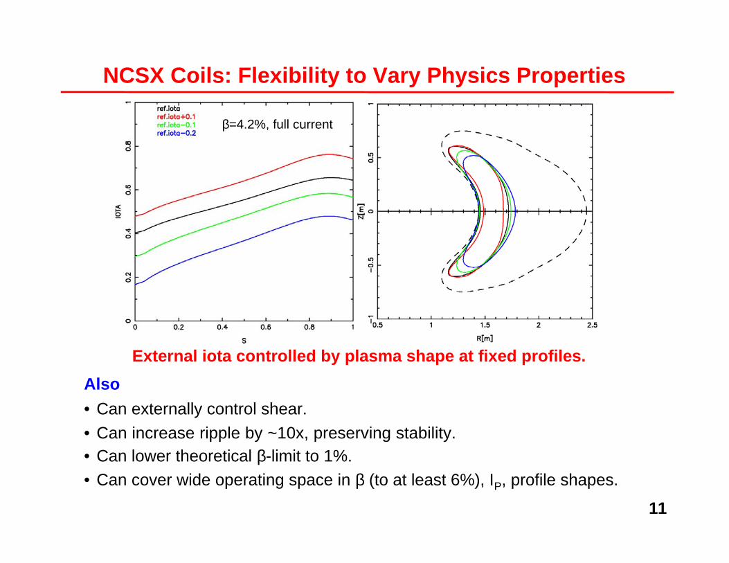
External iota controlled by plasma shape at fixed profiles.
Also
• Can externally control shear.
• Can increase ripple by ~10x, preserving stability.• Can lower theoretical β-limit to 1%.• Can cover wide operating space in β (to at least 6%), IP, profile shapes.
β=4.2%, full current
NCSX Coils: Flexibility to Vary Physics Properties

12
Edge Field Lines Have Long Connection Lengths
• L > 100 m desired for low-temperatures at
target → impurity control
• Ordered (not stochastic) field line
structure, expands near tips of bean
cross-section (envisioned divertor
location).
• Field lines stay close to boundary except
near divertor.
• Sets criteria for first wall placement to
ensure long connection lengths.
-0.8
-0.6
-0.4
-0.2
0
0.2
0.4
0.6
0.8
1 1.2 1.4 1.6 1.8
Z (
m)
R (m)
20 toroidaltransits
(~200 m)

13
NCSX Physics Design Summary
NCSXCoil and VV prototypes in 2003
First Plasma in 2007
• Optimized for high-beta compact QA
plasma with attractive physics properties.
• Access to high-beta state starting from
vacuum.
• Flexibility for physics experiments.
— Knobs to vary physics properties.
— Large operating space in β, IP, profile
shapes.
— Range of operating scenarios (high β,low ν*, long pulse).
• Space for divertor and first wall.
• Ample port access.
• Feasible engineering design.
— Engineering: B. E. Nelson, et al., FT/2-4.