UART6 User Guide and Reference Designs...
25
© Copyright 2011-2013 Xilinx . Ultra-Compact UART Macros for Spartan-6, Virtex-6 and 7-Series with PicoBlaze (KCPSM6) Reference Designs Ken Chapman 29 th March 2013 Release: 4 (Universal Asynchronous Receiver Transmitter)
-
Upload
trannguyet -
Category
Documents
-
view
244 -
download
1
Transcript of UART6 User Guide and Reference Designs...

© Copyright 2011-2013 Xilinx.
Ultra-Compact UART Macros for Spartan-6, Virtex-6 a nd 7-Series
with PicoBlaze (KCPSM6) Reference Designs
Ken Chapman
29th March 2013
Release: 4
(Universal Asynchronous Receiver Transmitter)

© Copyright 2011-2013 Xilinx.
Page 2
Disclaimer and Acknowledgements
Copyright © 2011-2013, Xilinx, Inc. This file contains proprietary information of Xilinx, Inc. and is protected under U.S. and international copyright and other intellectual property laws.
Notice of DisclaimerXilinx is disclosing this Application Note to you “AS-IS” with no warranty of any kind. This Application Note is one possible implementation of this feature, application, or standard, and is subject to change without further notice from Xilinx. You are responsible for obtaining any rights you may require in connection with your use or implementation of this Application Note. XILINX MAKES NO REPRESENTATIONS OR WARRANTIES, WHETHER EXPRESS OR IMPLIED, STATUTORY OR OTHERWISE, INCLUDING, WITHOUT LIMITATION, IMPLIED WARRANTIES OF MERCHANTABILITY, NONINFRINGEMENT, OR FITNESS FOR A PARTICULAR PURPOSE. IN NO EVENT WILL XILINX BE LIABLE FOR ANY LOSS OF DATA, LOST PROFITS, OR FOR ANY SPECIAL, INCIDENTAL, CONSEQUENTIAL, OR INDIRECT DAMAGES ARISING FROM YOUR USE OF THIS APPLICATION NOTE.
Acknowledgments
Thank you to Nick Sawyer for the Verilog equivalents of these macros.
Thank you to all the PicoBlaze users that offered to test and verify these macros. Your experiences and feedback really helped to improve the documentation and will make the use of these macros by all future users than much easier.

© Copyright 2011-2013 Xilinx.
Page 3
UART_TX6 and UART_RX6 Features
Unsurprisingly, the ‘uart_tx6’ macro provides a UART transmitter whilst the ‘uart_rx6’ provides a UART receiver. More surprising is that each macro includes a 16-byte FIFO buffer and yet each macro occupies only 5-Slices of a Spartan-6 or Virtex-6 device. Their combined size of 10-Slices equates to 1.7% of the smallest (XC6SLX4) Spartan-6 device and a ridiculously small 0.01% of the largest (XC6VLX760) Virtex-6 device so there should never be any problem finding space for them!
Both the transmitter and receiver have pre-defined fixed communication settings of 8-bit data, 1-stop bit and no parity all of which are the most common settings and adequate for the vast majority of applications. The baud rate (bit rate) is defined in your design by the application of enable pulses relative to a system clock frequency. Whilst many applications will require a standard baud rate such as 9600 or 115200 these macros can operate at any baud rate up to your clock frequency divided by 16 which means that baud rates in excess of 10mbps can also be achieved; UART does not have to mean slow! Whilst the macros do not immediately provide a soft or hardware handshake option the FIFO buffer signals facilitate the implementation of handshake schemes.
The UART6 macros can be used standalone in your design but they are ideally matched with the PicoBlaze processor (KCPSM6). Whilst there is nothing particularly special about UART communication, it is highly likely that your application will transmit and receive specific information such as text strings and data values and PicoBlaze (at only 26 Slices) will often make the implementation of your ‘protocol’ rapid and efficient.
16-ByteFIFO
data_in(7:0)
serial_out
buffer_readbuffer_write buffer_full
buffer_data_presentbuffer_half_full
clk
en_16_x_baud Transmitter8-bit, 1-Stop,
Non parity
uart_tx6
16-ByteFIFO
data_out(7:0)
serial_in
buffer_full
buffer_data_presentbuffer_half_full
clk
en_16_x_baud
Receiver8-bit, 1-Stop,
Non parity
uart_rx6
Except for the serial input to the receiver, which by the very nature of UART communication is asynchronous, all inputs and outputs of both macros are synchronous to the supplied clock and should be treated as such in your design. Parallel data is written to or read from the integral 16-byte FIFO buffers that provide a selection of status flags to be used as necessary by your application. The ‘en_16_x_baud’ input is used to define the baud rate of the serial communication relative to the clock frequency. Any data (characters) written to the transmit buffer will be automatically and continuously transmitted on ‘serial_out’ until the buffer becomes empty. Likewise, valid data (characters) received from ‘serial_in’ will be automatically written to the receiver FIFO.
buffer_reset buffer_reset

© Copyright 2011-2013 Xilinx.
Page 4
Applications of the UART Macros
For many years UART has been synonymous with RS232 (UART with ±12v signals) and the 9-way connector on the back of a PC often used to connect a serial mouse. Of course that serial port connector has been rapidly disappearing from machines as USB has become more dominant and popular. For a while it looked like UART would fade into history, but whilst it may look that way on most office desk tops it is still very much alive and well in our industry.
USB-UART
The legacy of RS232 is virtually everywhere and much of that equipment will remain in the field for many years to come. Furthermore the software programs associated with those pieces of equipment still require a ‘COM’ port to be connected. Companies such as FTDIchip ( www.ftdichip.com ) were quick to recognise that very soon it would be impossible to replace an old PC and developed some apparently simple USB to UART bridging devices. Combined with a ‘Virtual COM port’ driver these devices immediately saved a lot of people from a big problem. Not only that, these devices are so easy to use that they have given UART a future.
Not everything has to be fast, it just needs to be easy!
Whilst USB has many advantages for modern equipment it has to be said that its complexity is not one of them. When you need high speed connectivity and rapid plug-and-play capability then to some degree it is reasonable to accept the increased complexity in the hardware and software design. However, there are still many applications that only require a relatively low bandwidth communication link. For example, when a terminal is used to display text based status messages and allow commands to be entered on a keyboard for diagnostic purposes. From a hardware perspective the USB-UART devices can be thought of as a replacement for the RS232 level shifter device in the past and the virtual COM port driver avoids the need for special software to be developed.
UART is small
As the ‘uart_tx6’ and ‘uart_rx6’ macros prove, a UART can have an extremely small footprint. In contrast, a USB core could easily be expected to be at least 70 times bigger and still require an external PHY device; fine if your application needs a high bandwidth but otherwise a significant overhead.
On board connectivity and Micro-Controllers
At a board level a UART can provide a direct connection between components using LVTTL or whatever standard is convenient. Many Micro-Controller devices include UART peripherals (at a lower price than their USB equivalents) or implement UART purely in software (see pages 24-25 to see how this technique can be implemented in PicoBlaze) . For PICmicro devices the low pin count (2) requirement of UART is compelling and fuels the desire for this connection to be supported in the Spartan-6 or Virtex-6 device even though it is rich in pins itself. Again, it is unlikely that such applications have any requirement for high bandwidth and in fact the baud rate may be very low in the case of a PICmicro software method being employed. UART really is just a simple and convenient way to pass relatively small amounts of information between devices.

© Copyright 2011-2013 Xilinx.
Page 5
More Potential Applications of the UART Macros
The previous page covered the rather obvious uses of a UART for connections between units either on the same board or with a PC. On this page we can consider how the UART macros in a Spartan-6 or Virtex-6 can be exploited further in your designs.
data[7:0]UART_TX6
data[7:0]UART_RX6write
fullread
data_present
Clock Domain A Clock Domain B
Each clock domain is presented with a fully synchronous FIFO interface.
Providing the baud rate is defined to be the same ±5% at each end of the link the UART receiver naturally resynchronises at the start of each byte transfer for total reliability.
With only one signal bridging between the two clock domains it often helps to eliminate routing congestion associated with a single parallel FIFO implementation.
Higher speed connectivity
Whenever you design a board it is an extremely good idea to provide a general purpose header allowing connection to a few pins on the FPGA. At any time you can modify your FPGA design to bring out some signals of interest to be probed with an oscilloscope etc. Now consider how much information you display on a terminal by inserting a PicoBlaze and a UART in a design as well as the control you could have over that design. Note that a USB-UART device can be part of the cable you attach rather than adding unnecessary cost to your board ( e.g. http://www.ftdichip.com/Products/Cables/USBTTLSerial.htm ).
Longer distance connectivity made easy
The baud rate of these macros can be up to CLK/16 meaning that baud rates of 5mbps in Spartan-6 and 10mbps in Virtex-6 are achievable. Providing you define the same baud rate at both ends of each link in your system then nobody is forcing you to conform to a standard rate. For example, with a 100MHz clock the baud rate of 6.25mbps can be achieved (‘en_16_x_baud’ input is tied permanently High) supporting a transfer rate of up to 625 k-bytes/second. With each pair of UART macros only occupying 10-Slices, running multiple UART links in parallel is also a cost effective way to increase bandwidth.
Every time information needs to cross from one clock domain to another there is the potential for unreliable operation. Failure to recognise this can result in intermittent faults that can be very costly over time. Typically the default solution is to insert an asynchronous FIFO although this often comes with the burden of complexity and an undesirable resource cost. So providing the data rate is adequate, the UART6 macros can be a superior alternative.
Why not consider using LVDS for longer distance communication over larger boards or twisted pair cables? The differential standard will afford you greater protection from noise etc. Providing the data rate is adequate the naturally asynchronous nature of UART communication also avoids all those tricky requirements for clock forwarding or clock recovery circuits. The simplicity of a UART makes communication reliable and low power.
2 Test Points = Diagnostic Port
Crossing Clock Domains and on-chip links
Note that the link can buffer up to 32-bytes in total.
© Copyright 2011-2013 Xilinx.
Page 6
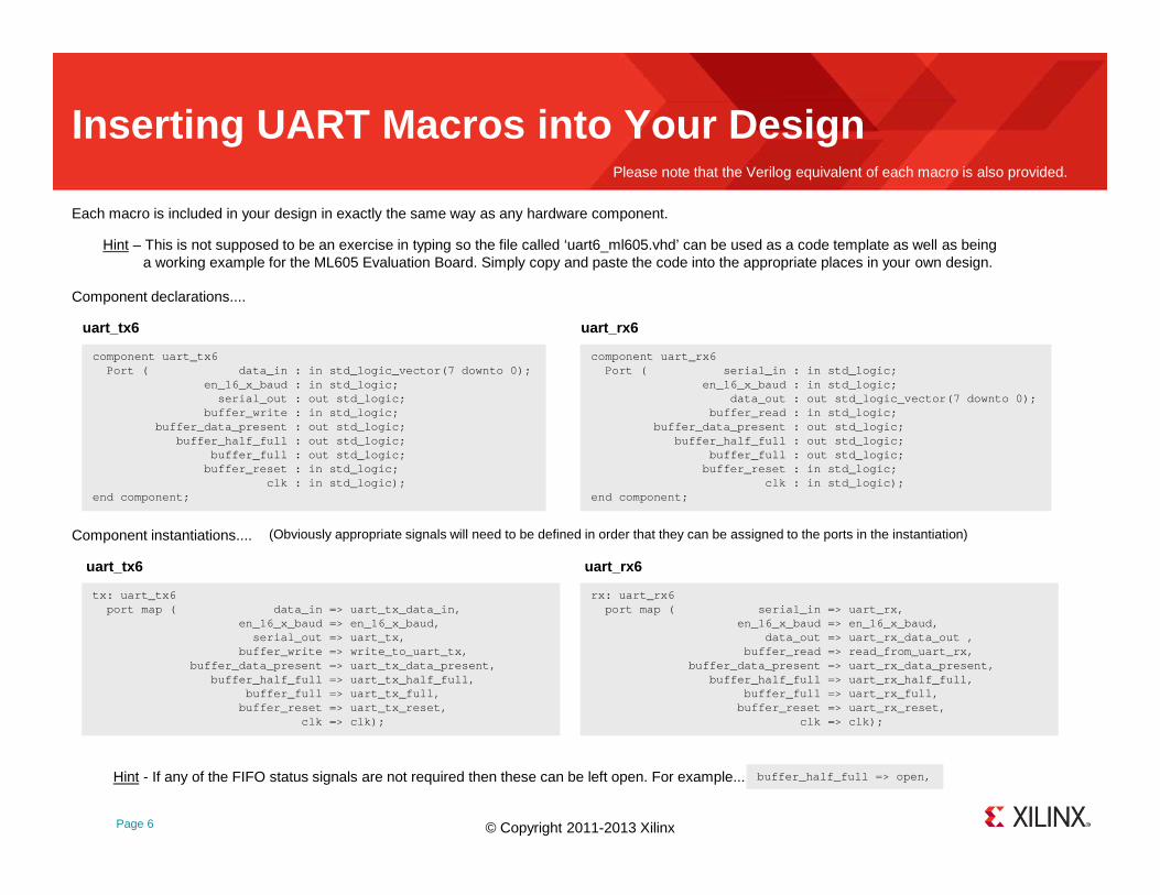
Inserting UART Macros into Your Design
Each macro is included in your design in exactly the same way as any hardware component.
component uart_tx6 Port ( data_in : in std_logic_vector(7 d ownto 0);
en_16_x_baud : in std_logic;serial_out : out std_logic;
buffer_write : in std_logic;buffer_data_present : out std_logic;
buffer_half_full : out std_logic;buffer_full : out std_logic;
buffer_reset : in std_logic;clk : in std_logic);
end component;
Hint – This is not supposed to be an exercise in typing so the file called ‘uart6_ml605.vhd’ can be used as a code template as well as beinga working example for the ML605 Evaluation Board. Simply copy and paste the code into the appropriate places in your own design.
(Obviously appropriate signals will need to be defined in order that they can be assigned to the ports in the instantiation)
Component declarations....
tx: uart_tx6 port map ( data_in => uart_tx_data_in,
en_16_x_baud => en_16_x_baud,serial_out => uart_tx,
buffer_write => write_to_uart_tx,buffer_data_present => uart_tx_data_present,
buffer_half_full => uart_tx_half_full,buffer_full => uart_tx_full,
buffer_reset => uart_tx_reset, clk => clk);
component uart_rx6 Port ( serial_in : in std_logic;
en_16_x_baud : in std_logic;data_out : out std_logic_vector(7 downto 0);
buffer_read : in std_logic;buffer_data_present : out std_logic;
buffer_half_full : out std_logic;buffer_full : out std_logic;
buffer_reset : in std_logic;clk : in std_logic);
end component;
rx: uart_rx6 port map ( serial_in => uart_rx,
en_16_x_baud => en_16_x_baud,data_out => uart_rx_data_out ,
buffer_read => read_from_uart_rx,buffer_data_present => uart_rx_data_present,
buffer_half_full => uart_rx_half_full,buffer_full => uart_rx_full,
buffer_reset => uart_rx_reset, clk => clk);
uart_tx6 uart_rx6
Component instantiations....
uart_tx6 uart_rx6
buffer_half_full => open,Hint - If any of the FIFO status signals are not required then these can be left open. For example...
Please note that the Verilog equivalent of each macro is also provided.

© Copyright 2011-2013 Xilinx.
Page 7
Defining the Baud Rate
IMPORTANT – ‘en_16_x_baud’ pulses must be synchronous to the clock (synchronous design!).
The only requirement that is specific to the serial communication is the definition of the baud rate. The baud rate is the number of bits per second at which information is transmitted and received. It is typically one of the well known standard rates associated with a computer based applications (e.g. 9600 or 115200) but it can be any rate you like provided that it is set to the same rate at both ends of a communication link. Each byte of data (or character) is transmitted and received using 10 bits comprising a start bit (‘0’), the 8-bit data (transmitted LSB first) and a stop bit (‘1’).
en_16_x_baud
en_16_x_baud
START STARTSTOP75 642 310
Bit Period = Baud Rate
1Example: 9600 baud = Bit period of 104µs
Hint – The overhead of start and stop bits means that the maximum data rate is 8/10 of the baud rate. If you have a specific requirements to transfer data then remember to take this into account when defining the baud rate of your communication link. For example, to transfer 1M-byte/second the minimum baud rate must be 1MHz × (8-bits of data + 2) = 10,000,000 BAUD. That’s 10MHz rather than 8MHz.
This input to the macros is used to define the desired baud rate by applying a series of enable pulses at a rate that is 16 times greater than the serial bit rate. This in turn is derived from the system clock which is of a known frequency.
en_16_x_baud
uart_tx6
serial_out
BAUDGeneration
clk
en_16_x_baud
uart_rx6
serial_in
clk
clk
IMPORTANT – The ‘en_16_x_baud’ signal should be a series of single clock cycle pulses used to enable the UART macros for one rising edge of the clock at a time. Do not make the mistake of applying a square wave ‘clock’ waveform that is 16 times the frequency of the baud rate!

© Copyright 2011-2013 Xilinx.
Page 8
Defining the Baud Rate
For the majority of applications the baud rate generation takes the form of a simple counter. This scheme is best explained by a real example in which a Spartan-6 device with a 50MHz clock is required to communicate with a PC at a baud rate of 9600.....
Note that the synchronous reset on the counter means that there are 326 states with values 0 through to 325. It is the total number of states that correctly defines the pulse rate so be careful how you specify the terminal count value in your code.
Counter
RST
Q=325 en_16_x_baud
50MHz
Hint – The maximum baud rate is CLK/16 and is achieved by tying the ‘en_16_x_baud’ input permanently High thereby avoiding any requirement for a baud generation circuit. This is ideal for point to point links whenever the same nominal clock frequency is available at the end of each link. No need for phase locked clocks or clock forwarding. Please also see ‘Improving Baud Accuracy’ section for high baud rate example.
Hint – See ‘Improving Baud Accuracy’ on pages 21-23 if rounding results in an undesirable deviation from the desired rate.
signal baud_count : integer range 0 to 325 := 0; signal en_16_x_baud : std_logic := '0';
baud_rate: process(clk)begin
if clk'event and clk = '1' thenif baud_count = 325 then
baud_count <= 0;en_16_x_baud <= '1';
elsebaud_count <= baud_count + 1;en_16_x_baud <= '0';
end if;end if;
end process baud_rate;
1) The ‘en_16_x_baud’ signal must therefore have a pulse rate of 16 × 9600 = 153,600 pulses per second.
2) With a 50MHz clock this equates to one enable pulse every 50,000,000 / 153,600 = 325.52 clock cycles.To be practical we round this to the nearest integer of 326.
3) Check the effect of rounding on the baud rate..... (50,000,000 / 326) / 16 = 9586 baud which is just 0.15% slower than target (assuming clock is perfect).Providing there is less than 5% difference between the baud rate of the transmitter and receiver forming a communication link then it should work.
4) Implement your baud generation counter circuit. The following example uses a signal defined as an integer to make this really easy....
Hint – “My simulation does not work”! Please be aware that many designers have allowed themselves to be confused by an attempt to simulate a design containing the UART6 macros; they simply forget that baud rate is often significantly slower than their clock and fail to simulate for enough cycles. In the above example the transmission of one byte (or character) will take 10 bits × 16 enable pulses × 326 clock cycles = 52,160 clock cycles; a long simulation!
Hint – Similar code in VHDL and Verilog is provided in the two reference designs

© Copyright 2011-2013 Xilinx.
Page 9
Transmitting Data with ‘uart_tx6’
To transmit data (or characters) you simply need to write 8-bit values into the FIFO buffer; the UART will automatically transmit any characters that are present in the buffer at the baud rate defined by ‘en_16_x_baud’ (and the clock frequency) until the FIO buffer is empty. The FIFO is fully synchronous with the clock (clk). 8-bit data or characters presented to the ‘data_in ’ port will be written into the FIFO on the rising edge of the clock when the ‘buffer_write ’ control is active High (1). This obvious scheme facilitates the writing of individual characters or bursts of characters as required by the application.
16-ByteFIFO
data_in(7:0)
serial_out
buffer_write buffer_full
buffer_data_presentbuffer_half_full
clk
en_16_x_baud Transmitter8-bit, 1-Stop,
Non parity
uart_tx6
buffer_reset
data_in(7:0)
buffer_write
clk
54H 69H 6DH 65H
‘T’ ‘i’ ‘m’ ‘e’
In this example the text string ‘Time’ is written to the transmitter FIFO using a combination of a single character write followed by a burst write of 3 characters.
buffer_full - Whilst it is possible to write one character into the FIFO every clock cycle the UART transmitter will always take many more clock cycles to serially transmit each character (e.g. 8,680 clock cycles at 115,200 baud using a 100MHz clock). It is therefore extremely easy to fill the FIFO with 16 bytes of data before the first character has been transmitted. It is vital that no attempt is made to write more data into the FIFO if the ‘buffer_full’ flag is active High (1). The most common technique employed in an application is to first test that ‘buffer_full’ is Low (0) before writing only one character to the transmitter FIFO. If the full flag is active then the application waits for it to return Low before writing just one more character and testing the ‘buffer_full’ flag again.
buffer_reset - An active High (1) on the ‘buffer_reset’ input will synchronously reset the FIFO buffer on the corresponding rising edge of the clock. Any data in the buffer will be lost and all flags with be cleared. This is typically only required when rebooting a system or following a buffer overflow (which is best avoided anyway). Note that if a reset is applied whilst data is being transmitted then the character being transmitted at that time will probably appear corrupted although that should be insignificant compared with the buffer contents being discarded!
buffer_half_full - The ‘buffer_half_full’ flag will be active High (1) whenever the FIFO contains 8 or more characters pending transmission. This can be useful to some applications which prefer to write to the transmitter FIFO in small bursts rather than one character at a time. By first testing that the ‘buffer_half_full’ flag is Low (0) the application will know that up to 8 bytes of information can be written in a burst without needing to check the full flag between each write.

© Copyright 2011-2013 Xilinx.
Page 10
Transmitting Data with ‘uart_tx6’
data_in(7:0)
buffer_write
clk
buffer_data_present
buffer_data_present - The ‘buffer_data_present’ flag is active High (1) at any time that the FIFO buffer contains one or more characters. Alternatively, it can be said that the buffer is empty when this flag is Low (0). Whilst the majority of applications ignore this flag it can be useful in two principle ways....
Hint - In some applications it is possible to predict in advance that the FIFO buffer will never become full and all flags can be ignored. This technique can apply if the ‘packets’ of information written to the transmitter FIFO always contain less than 16 characters and those packets occur at such a rate that it is guaranteed that the UART will have had adequate time to transmit each packet such that the FIFO will be empty before the next one. For example, an application could transmit the time of day using a text string with the format ‘hh:mm:ss’. This is a packet containing 8 characters, which if transmitted at one second intervals absolutely guarantees that the buffer will not become full providing the baud rate is more than 80 (which it normally is!).
Hint - The effective depth of the FIFO buffer could be increased by inserting an additional FIFO between the application and the UART Transmitter. For example the FIFO mode of a Block Memory (BRAM) could significantly increase the depth of the buffer. The application would observe the status flags of the additional FIFO and write information to it as appropriate. A simple state machine would then automate the process of reading data from this FIFO and writing it into the UART transmitter FIFO providing ‘buffer_full’ was Low.
Hint – It may be undesirable in some applications for everything to ‘stall’ whilst waiting for the UART to transmit data and free space in the FIFO. However, if the FIFO is full then it is also known that the UART transmitter already has enough information to keep it actively transmitting for another 16 character periods. During this time (e.g. ~1.38ms at 115,200 baud) the application could be gainfully employed to perform other tasks whilst the UART macro continues to transmit. When the application returns to the UART the buffer could, if required, be refilled to capacity and left once again whilst servicing other tasks.
START 0 1 2 3 4 5 6 7 STOP
8,680 clock cycles (115,200 baud at 100MHz)
Serial transmission not in scale with clock waveform shown above!
2) The diagram below indicates how the ‘buffer_data_present’ flag is set High when the first character is written to the buffer. Then, providing no other characters are written, the flag returns Low once the last bit of that character has been transmitted. This can be used by the application to implement either a hardware or soft (XON/XOFF) flow control scheme by only writing one character to the buffer providing the receiver at the other end of the serial line is indicating ‘clear to send’ (CTS). Although this effectively wastes much of the FIFO capability it ensures that the transmission can be stopped within one character when required to do so.
1) If it is known that the FIFO is empty then it is safe to write a burst of up to 16 characters without needing to test the ‘buffer_full’ flag between each write.

© Copyright 2011-2013 Xilinx.
Page 11
Receiving Data with ‘uart_rx6’
Data (or characters) are received automatically at the baud rate defined by ‘en_16_x_baud’ (and the clock frequency) and then stored in the receiver FIFO buffer. The FIFO is fully synchronous with the clock (clk). When active High (1), the ‘buffer_data_present ’ flag is used to signify to the application that there is at least one character ready to be read which will be present on the ‘data_out ’ port. The application should capture this data and then provide an active High (1) level for one rising edge of the clock to the ‘buffer_read ’ control input. The receiver FIFO will then present the next character to be read on the ‘data_port’ or drive the ‘buffer_data_present’ flag Low (0) to indicate that the FIFO is now empty. This obvious scheme facilitates the reading of individual characters or bursts of characters (if available).
data_out(7:0)
buffer_read
clk
‘T’ = 54H
In this example the character ‘T’ is received and automatically stored in the FIFO buffer which was previously empty. After a few clock cycles the application responds to the ‘buffer_data_present’ flag and reads the FIFO so that it is empty once again.
buffer_read16-ByteFIFO
data_out(7:0)
serial_in
buffer_full
buffer_data_presentbuffer_half_full
clk
en_16_x_baud
Receiver8-bit, 1-Stop,
Non parity
uart_rx6
buffer_reset
Hint – The ‘buffer_read’ control is more accurately described as being an “I have read you” control. Unlike the ‘buffer_write’ control that is an instruction to write data into the transmitter FIFO on the corresponding rising clock edge, the data presented on the ‘data_out’ port of the receiver FIFO can be read at any time that it is valid (e.g. ‘T’ shown in the diagram above could have been read anywhere in the green zone) and the ‘buffer_read’ is purely the indication that the FIFO can now discard that data and move on to the next character and/or update the status flags.
buffer_data_present
Hint – The ‘buffer_read’ control should only be asserted when ‘buffer_data_present’ is High indicating that there was valid data to be read from the buffer. The diagram on the right shows a burst read of characters ‘i’, ‘m’ and ‘e’ resulting in the buffer becoming empty. Note how ‘buffer_data_present’ is used to drive ‘buffer_read’ Low to prevent a further illegal read. Asserting ‘buffer_read’ when ‘buffer_data_present’ is Low does not itself result in incorrect operation of the FIFO but it does imply that the application may have read ‘data_out’ when it was not valid to do so. There is also a risk that that the ‘buffer_read’ occurs at exactly the same time that a character received from the serial input is being written into the FIFO buffer with the net effect being that the received character is missed by the application.
data_out(7:0)
buffer_read
clk
buffer_data_present
69H 6DH 65H

© Copyright 2011-2013 Xilinx.
Page 12
Receiving Data with ‘uart_rx6’
buffer_half_full - The ‘buffer_half_full’ flag will be active High (1) whenever the receiver FIFO contains 8 or more characters waiting to be read by the application. This can be very useful in several ways:-
buffer_reset - An active High (1) on the ‘buffer_reset” input will synchronously reset the FIFO buffer on the corresponding rising edge of the clock. Any data in the buffer will be lost and all flags will be reset. This is typically only required when rebooting a system or following a buffer overflow (which is best avoided anyway). Note that if a reset is applied whilst data is being received then the character being received at that time will still be written into the receiver buffer providing the ‘buffer_reset’ is Low when the stop bit of that character is received (assuming it is a valid).
buffer_full - The receiver FIFO buffer can hold up to 16 characters. Obviously this means that up to 16 characters can be received from the serial input before the application needs to read any of them from the buffer. The ‘buffer_full’ flag will be driven active High (1) as soon as the 16th character is received since design start or the when the last read occurred. If this situation be allowed to develop in a application then it should be treated as a matter of some urgency to read at least one character from the buffer before a 17th character is received and results in a buffer overflow. Remember that it can appear to take a relatively long time (e.g. 8,680 clock cycles at 115,200 baud using a 100MHz clock) for the next character to be received so a rapid response to ‘buffer_full’ should avoid any loss of data. If however, the application is unable to determine the moment at which the ‘buffer_full’ flag was asserted then it will almost certainly need to assume that an overflow has occurred and take suitable recovery steps.
1) If the ‘buffer_half_full’ flag is used to alert the application to the requirement to start reading from the buffer then the remaining half of the buffer (enough to receive another 8 characters) would generally provide adequate time for the application to schedule the buffer reading task in the near future rather than interrupting its current task. This ability to be more ‘relaxed’ is often very welcome. Using this scheme the ‘buffer_full’ flag should never be seen to go High and therefore be assigned the status of ‘overflow’ or ‘communication error’ should it ever occur.
2) The ‘buffer_half_full’ flag is ideally suited for the implementation of either a hardware or soft (XON/XOFF) flow control scheme. When the flag isasserted the receiving application can indicate to the transmitter at the other end of the link that it should cease transmission. By the very nature of the UART arrangement it is almost impossible to stop the transmission immediately but since there is enough remaining space in the receiver FIFO buffer to store another 8 characters before an overflow can occur then this provides a high margin of safety.
3) Some application have more important and compelling tasks to perform than checking to see if there is anything waiting to be read from the receiver FIFO. Likewise, handling one character at a time when each character is received relatively slowly can be a distraction from other tasks. In these situations the ‘buffer_half_full’ flag can be used as the trigger to tell the application that there are at least 8 characters waiting to be read. Not only may this be considered enough information to be worthy of processing but it also means the application can burst read up to 8 characters without needing to check the state of the ‘buffer_data_present’ flag between each read operation.
Hint – If the FIFO is full then the application can burst read up to 16 characters without needing to check the state of the ‘buffer_data_present’ flag.

© Copyright 2011-2013 Xilinx.
Page 13
Debugging a UART Connection
If your UART communication is not working then fortunately there is nearly always a simple reason and an easy solution. As with most successful debugging, it is often solved by breaking the design down into smaller pieces and checking what does and what does not work. So here are the steps recommended to debug a UART connection that should solve 90% of cases. The next 9% of cases will be solved by going over them again more carefully! ☺
1) Read the documentation again!- If you are simulating a design rather than using hardware then especially read the “My simulation does not work” Hint on page 8.
2) Check your communication settings at your terminal. Do they match your baud rate? Check 8-bit, 1-stop, no parity and no handshake.
3) Check your design again.- The way you have connected the UART macros in your design.- The way you have defined the baud rate (you are generating synchronous enable pulses aren’t you?).- Your UCF file defines the correct pins on your FPGA; it’s easy to swap serial input and serial output pins!- Cables are plugged in correctly etc.- The FPGA is configured isn’t it?
4) If nothing seems to make it work then create a dummy design in which you define a ‘wire’ directly between your serial input and serial output.- This is a ‘loop-back’ connection and completely eliminates the UART macros and the rest of your design. - Typing on your keyboard should result in the same characters being displayed as they go down and back up the cable.
- Likewise an embedded design should be able to see characters echo back.- If this doesn’t work then you have a problem with your cable or your loop-back design. - Check your UCF pin assignments again.
- Are they the correct pins for your hardware and have you got them assigned the right way round?- Check your cable
- Ideally disconnect it and physically short the connections at the end of the cable.- Note that serial cables either come as straight-through (pin3 to pin3) or swap-over (pin3 to pin4) so be sure which you need and use.
5) If the loop-back worked then focus only on the ‘uart_tx6’ macro first and continuously transmit a known ASCII character (e.g. ‘A’ = 41hex).- If you do not receive characters then.....
- Check your baud rate definition again along with 8-bit, 1-stop, no parity and no handshake. - Check how you write to the ‘uart-tx6’ macro and check to see if the transmitter buffer flags are changing as expected.
- If you do receive characters then....- Implementing a loop-back of data received from ‘uart_rx6’ to resolve your receive path.- Check status of flags on ‘uart_rx6’.

© Copyright 2011-2013 Xilinx.
Page 14
PicoBlaze Reference Designs with UART6 Macros
Two simple reference designs are provided with KCPSM6 and the UART6 macros. As provided, the source files target the ML605 Virtex-6 Evaluation Kit and the ATLYS Spartan-6 Design Platform but both can be used as reference for your own designs and are easy to port to other hardware. The primary objective of the designs is to illustrate the typical hardware design and PSM assembler code required when using the UART6 macros with KCPSM6 and for this reason the two designs are almost identical in this area. However, the designs do have some subtle differences as well as unique features, all of which are intended to provide educational examples as well as reusable code for your own designs. Please do take the time to look at both designs; even if you plan to work immediately with one of the target boards there are lessons to be learnt from both designs and different PSM code for you see and reuse.
Common to both designs...
uart6_ml605
uart6_atlys
- The KCPSM6 processor interfaces to the UART6 receiver and transmitter macros using the same input and output ports. - The baud rate is set to 115200 (This is also the default baud rate for the PicoTerm terminal provided). - Programs (PSM code) illustrate UART macro interaction and communication with terminal (keyboard and display) .- Source files only; you must assemble the PSM file to generate the program definition file and then implement the design to configure the device.
- Hardware design defined by..... ‘uart6_ml605.vhd’ (verilog version also provided) and ‘uart6_ml605.ucf’.- ML605 provides a 200MHz differential clock which is divided by 4 using a ‘BUFR’ to form a 50MHz clock.
Note how the baud rate is defined relative to the 50MHz clock and that software delays in PSM code also relate to 50MHz.- Program memory is set to ‘V6’ due to target being a Virtex-6 device. The initial program size is set to 2K instructions (1 BRAM in a Virtex-6).- KCPSM6 code defined by.... ‘uart_control.psm’ and ‘uart_interface_routines.psm’. - Program illustrates interaction with the user of a terminal allowing keyboard entry of characters and performing ASCII, hex and decimal conversions.- Can be used with any appropriately configured terminal (e.g. HyperTerminal) but PicoTerm should make setting it up easy.
- Hardware design defined by..... ‘uart6_atlys.vhd’ (verilog version also provided) and ‘uart6_atlys.ucf’.- ATLYS provides a 100MHz clock which is used directly. Note that the baud rate and software delays in PSM code are defined relative to 100MHz.- Program memory is set to ‘S6’ due to target being a Spartan-6 device. The initial program size is set to 1K instructions (1 BRAM in a Spartan-6).- Additional ports interface with the 8 switches and 8 LEDs on the ATLYS board, an interrupt is generated at one second intervals and a reset button is used. - KCPSM6 code defined by.... ‘atlys_real_time_clock.psm’, ‘PicoTerm_routines.psm’ and ‘soft_delays_100mhz.psm’. - The program exploits and illustrates several of the unique features that PicoTerm provides and therefore PicoTerm must be used.- Although simple, the program provides examples of interrupt handing and hardware interaction in addition to multiple UART communications.
Differences...
An overview of the differences in each design is given below and the following pages provide further details (each source file also contains descriptions).
Hint – README.txt includes UART device pin constraints for other popular boards

© Copyright 2011-2013 Xilinx.
INPUT
Page 15
uart6_ml605
address
instruction bram_enable
interrupt
sleep
reset
interrupt_ack
port_id
out_portin_port
k_write_strobe
read_strobe
write_strobe
kcpsm6
instructionenable
uart_control
rdlclk
address
clk
‘0’
buffer_write
data_in serial_out
uart_tx6
clk
buffer_data_present
buffer_half_full
buffer_full
buffer_reset
[0]
[1]
[2]
en_16_x_baud
data_outserial_in
uart_rx6
clk
buffer_data_present
buffer_half_full
buffer_full
buffer_reset
[3]
[4]
[5]
en_16_x_baud
buffer_read
R
COUNTER
=26
115200 baud with 50MHz clock
uart_rx
uart_tx
Input Ports00 – UART status01 – UART Rx data
clk200_p
[0]
[0]
[0]
[1:0]
write_to_uart_tx
read_from_uart_tx
[0]
CE
K-Output Port1 – UART reset
read_strobe
KCPSM6 executes an INPUT instruction that reads ‘data_out’ from ‘uart_rx6’. ‘read_strobe’ is used to qualify the ‘port_id’ to generate a ‘buffer_read’ pulse indicating to the receiver buffer that the data has been read and can now advance to the next character and/or update the receiver buffer flags.
KCPSM6 executes an OUTPUT instruction that writes data directly into ‘uart_tx6’. ‘write_strobe’ qualifies the ‘port_id’ to generate the ‘buffer_write’ pulse. Note that this must be a combinatorial decode (no pipeline!).
This design only uses 1-bit of address due to low number of ports required (adjust as necessary).
[0]
[1]
This diagram represents the circuit provided in ‘uart6_ml605.vhd’ (or ‘.v’) but the same ports are assigned to the UART macros in ‘uart6_atlys.vhd’.
‘buffer_read’
50MHz
‘buffer_write’
clk
clk200_nDivide by 4
JTAG Loader
Output Port(write strobe)
01 – UART Tx data
Input Port (read strobe)
01 – UART Rx
1-bitselects2 ports

© Copyright 2011-2013 Xilinx.
Page 16
uart6_atlys
address
instruction bram_enable
interrupt
sleep
reset
interrupt_ack
port_id
out_portin_port
k_write_strobe
read_strobe
write_strobe
kcpsm6
instructionenable
atlys_real_time_clock
rdlclk
address
clk
‘0’
buffer_write
data_in serial_out
uart_tx6
clk
buffer_data_present
buffer_half_full
buffer_full
buffer_reset
[0]
[1]
[2]
en_16_x_baud
data_outserial_in
uart_rx6
clk
buffer_data_present
buffer_half_full
buffer_full
buffer_reset
[3]
[4]
[5]
en_16_x_baud
buffer_read
R
COUNTER
=53
115200 baud with 100MHz clock
uart_rx
uart_tx
Input Ports00 – UART status01 – UART Rx data02 – Switches
Output Port (write strobe)01 – UART Tx data
clk
[1]
[0]
[0]
[1:0]
write_to_uart_tx
read_from_uart_tx
[1:0]
CE
K-Output Port1 – UART reset
Input Port (read strobe)01 – UART Rx
[0]
[1]
This diagram represents the circuit provided in ‘uart6_atlys.vhd’ (or ‘.v’). Note that the UART interface is the same as in ‘uart6_ml605.vhd’.
100MHz
switch[7:0]reset_b
rdl
CE
led[7:0]
[1]Output Port02 – LEDs
[0]
R
COUNTER =99,999,999
interrupt
JTAG Loader
Interrupt once per second
2-bitsselects3 ports(4 max)

© Copyright 2011-2013 Xilinx.
Page 17
KCPSM6 Interface with UART6 Macros
input_ports: process(clk)begin
if clk'event and clk = '1' thencase port_id(0) is
-- Read UART status at port address 00 hexwhen '0' => in_port(0) <= uart_tx_data_present;
in_port(1) <= uart_tx_half_full;in_port(2) <= uart_tx_full; in_port(3) <= uart_rx_data_present;in_port(4) <= uart_rx_half_full;in_port(5) <= uart_rx_full;
-- Read UART_RX6 data at port address 01 hexwhen '1' => in_port <= uart_rx_data_out;
when others => in_port <= "XXXXXXXX"; end case;
if (read_strobe = '1') and (port_id(0) = '1') thenread_from_uart_rx <= '1';
elseread_from_uart_rx <= '0';
end if; end if;
end process input_ports;
The extracts of VHDL shown on the left hand side (from ‘uart6_ml605.vhd’) define the three ports forming the interface with the UART macros. Below are a set of CONSTANT declarations in the PSM code that correspond with the hardware port allocations and enable the PSM code routines to be more portable as well as easier to write and understand.
write_to_uart_tx <= '1' when (write_strobe = '1') and (port_id(0) = '1')else '0';
constant_output_ports: process(clk)begin
if clk'event and clk = '1' thenif k_write_strobe = '1' then
if port_id(0) = '1' thenuart_tx_reset <= out_port(0); uart_rx_reset <= out_port(1);
end if;end if;
end if; end process constant_output_ports;
CONSTANT UART_status_port, 00 CONSTANT UART_Tx_data_present, 00000001'b CONSTANT UART_Tx_half_full, 00000010'bCONSTANT UART_Tx_full, 00000100'b CONSTANT UART_Rx_data_present, 00001000'bCONSTANT UART_Rx_half_full, 00010000'bCONSTANT UART_Rx_full, 00100000'b
CONSTANT UART_TX6_output_port, 01
CONSTANT UART_RX6_input_port, 01
CONSTANT reset_UART_port, 01CONSTANT UART_tx_reset, 00000001'bCONSTANT UART_rx_reset, 00000010'bCONSTANT UART_reset, 00000011'b ;reset Tx and RxCONSTANT UART_operate, 00000000'b ; Tx and Rx free to operate
Reading ‘uart_rx6’ buffer captures the data and generates the ‘buffer_read’ pulse from the ‘read-strobe’.
All code shown below is provided in ‘uart6_ml605.vhd’ (or ‘.v’) and ‘uart_interface_routines.psm’ (or ‘PicoTerm_routines.psm’).
Hint - When decoding more bits of ‘port_id’ then your code wouldtake the form....
and (port_id(2 downto 0) = “001 ")
‘uart6_atlys.vhd’ (or ‘.v’) is slightly different due to having additional ports to read switches and drive LEDs but the UART port assignments remain the same.

© Copyright 2011-2013 Xilinx.
Page 18
KCPSM6 Interface with UART6 Macros
UART_RX: LOAD s1, 167'd ;Timeout = 167 x ( 6 instructions x 2 clock cycles)rx_timeout: INPUT s0, UART_status_port
TEST s0, UART_Rx_data_present ;Z=0 when data presentJUMP NZ, read_RxSUB s1, 1'dRETURN Z ;Timeout returns w ith Z=1JUMP rx_timeout;
read_Rx: INPUT s5, UART_RX6_input_port ;read cha racter from bufferRETURN
These simple PSM subroutines enable characters to be transmitted and received using the UART macros.
Transmit
It is vital that no characters are written to the transmitter FIFO buffer if it is full. This routine tests the ‘buffer_full’ flag and unless it is Low (0) it will wait until it is before executing the OUTPUT instruction to write data to the transmitter FIFO.
Receive
The key requirement is that a read only occurs when there is a character waiting to be read from the receiver FIFO buffer. So this routine tests the ‘buffer_data_present’ flag to ensure that it is High (1) before executing the INPUT instruction to read a character.
This routine also includes a timeout to prevent KCPSM6 waiting indefinitely for ‘uart_rx6’ to receive a valid character. This could be used to detect a break in communications or allow KCPSM6 to perform some other tasks.
reset_UART_macros: OUTPUTK UART_reset, reset_UART_p ortOUTPUTK UART_operate, reset_UART_port
Reset – Generates active High reset pulses with a durationof 2 clock cycles to both ‘uart_tx6’ and ‘uart_rx6’.
Hint – The ‘timeout’ feature can be removedfor many applications.
;-------------------------------------------------- ------------------------------------; Routine to attempt to receive one character from the UART Receiver (UART_RX6);-------------------------------------------------- ------------------------------------;; This routine will attempt to receive one characte r from the 'UART_RX6' macro, and if; successful, will return that character in registe r 's5' and the Zero flag will be; reset (Z=0).;
UART_TX: INPUT s0, UART_status_port ;Check if buffer is fullTEST s0, UART_Tx_fullJUMP NZ, UART_TXOUTPUT s5, UART_TX6_output_port ;write character to bufferRETURN
;-------------------------------------------------- ------------------------------------; Routine to send one character to the UART Transmi tter (UART_TX6);-------------------------------------------------- ------------------------------------;; This routine will transmit the character provided in register 's5'.;
All code shown below is provided in ‘uart_interface_routines.psm’.
;-------------------------------------------------- -----------------------------; Routine to reset UART Buffers inside 'UART_TX6' a nd 'UART_RX6';-------------------------------------------------- -----------------------------
‘PicoTerm_routines.psm’ has the same ‘UART_TX’ code but contains an enhanced ‘UART_RX’ routine (plus additional routines) to exploit PicoTerm features.

© Copyright 2011-2013 Xilinx.
Page 19
Example Program: uart_control.psm
The ‘uart_control.psm’ program includes several routines that demonstrate typical uses of the UART macros when communicating with a simple terminal such as PicoTerm (provided with PicoBlaze and the UART macros) or HyperTerminal. The screen capture below shows PicoTerm when connected to the ML605 Evaluation Board running the reference design. Note that the ML605 has a USB-UART bridge with a corresponding virtual COM port on the PC.
Printing or displaying text strings is a very common application. The STRING directive combined with the LOAD&RETURN instruction makes sending text strings to ‘uart_tx6’ straightforward.
This reference code implements a hexadecimal to decimal converter . In so doing it receives characters entered by the user on their keyboard via the ‘uart_rx6’ and performs the following...
These text strings pick up on the version informationprovided by the KCPSM6 assembler and the ‘hwbuild’ generic in the VHDL design. A very simple way to track the build state and date/time stamp any design.
The display is cleared by KCPSM6 sending ANSI Escape Sequences using ‘uart_tx6’.
- Accepts upper or lower case characters.Converts lower to upper case.
- ASCII Hex to binary conversionIncluding trap for non-hex characters.
- Display of binary value in ASCII Hex.- 16-bit binary to 5-digit BCD
(Binary Coded Decimal)- Display of BCD with leading zero blanking. PicoTerm is pre-configured to suit the PicoBlaze UART6 macros with a default 115200 baud rate.
If you use a different terminal then it will need to be configured follows to work with this design.... 115200 Baud, 1 Stop Bit, No parity and No Handshake.ASCII setup to perform a line feed when receiving a carriage return.
Error checking and reporting.

© Copyright 2011-2013 Xilinx.
Page 20
Example Program: atlys_real_time_clock.psm
The ‘atlys_real_time_clock.psm’ program also displays text and interacts with user keyboard entries in a similar way to the ‘uart6_ml605.psm’ program (see previous page). However, this program specifically exploits and demonstrates some of the special features of PicoTerm so PicoTerm must be used. The hardware design includes additional ports which interface with 8 switches and 8 LEDs on the ATLYS board. The program reads the real switches on the ATLYS board and sets the virtual LEDs within PicoTerm and reads the virtual switches within PicoTerm and drives the real LEDs on the ATLYS board . The program also has an interrupt service routine (ISR) that responds to the interrupts generated at one second intervals to maintain a real time clock.
PSM code uses the STRING directive combined with the LOAD&RETURN instruction to print text strings . Text colour can be set in the PicoTerm Main terminal window.
Hint - ‘PicoTerm_README.txt’ includes descriptions of the PicoTerm features as well as basic usage. ‘PicoTerm_routines.psm’ contains routines to work with each of the features with full descriptions.
Characters received from the keyboard are echoed back to the main screen. The ASCII code is also
displayed on the amber virtual LEDs by transmitting a Device Control String (DCS)
The physical switches are read and a DCS transmitted to set the Red/Green virtual LEDs
Interrupts trigger an ISR which implements a real time clock (hours, minutes and seconds). The time is displayed on the PicoTerm virtual7-Segment Display window via the transmission of Device Control Strings (DCS).The program will also transmit a DCS to confirm that PicoTerm is connected and another DCS to request the time from your PC.
KCPSM6 transmits a DCS requesting the status of the virtual switches and then receives a DCS response with which it drives the physical LEDs.

© Copyright 2011-2013 Xilinx.
Page 21
Improving BAUD Accuracy
As described on pages 7 and 8 the baud rate is defined by the rate at which enable pulses are applied to the ‘en_16_x_baud’ input of each macro. In the vast majority of cases the desired baud rate will be achieved by a simple division of the system clock. Generally speaking an accuracy of ±5% is adequate but it should be remembered that this figure must account for the total potential difference between the baud rate of the transmitter and the baud rate of the receiver forming the link. As such, it would be unwise to consume all of the ±5% budget for your end of a link with the assumption that the other end is perfect.
Except in situations where the desired baud rate is an exact integer division of the system clock frequency then the potential for greater baud rate inaccuracy increases the higher the desired baud rate is relative to the clock. This is best covered by an example....
Desired baud rate = 115,200 Hence the target ‘en_16_x_baud’ pulse rate = 1,843,200 Hz
Reference clock = 25MHz
This implies that the ‘en_16_x_baud’ pulses should be derived by dividing the 25MHz clock by 13.56 which does not appear to be possible so we select the nearest integer value of 14 and see what happens.....
Counter
RST
Q=13 en_16_x_baud
25MHz
0 1 2 13
The result is obviously that the ‘en_16_x_baud’ signal pulses High for one cycle every 14 clock cycles and this corresponds with a pulse rate of 1,785,714Hz. Consequently the UART baud rate will be 111,607 which is 3,592 slower than target and at 3.1% lower than desired it is certainly encroaching on the margins for reliable operation.
One solution is to lower the baud rate or increase the clock rate but in most cases we have been ‘dealt the playing cards’ and rarely have the luxury to change either. In situations where you really want to exploit a higher baud rate it is also undesirable to lower the baud rate and a higher frequency clock may be impossible to work with. So we need to achieve the equivalent of a non-integer division and fortunately that is easier to implement than you may first think it to be....
025MHz
en_16_x_baud
Q

© Copyright 2011-2013 Xilinx.
Page 22
Improving BAUD Accuracy
The period of each serial bit is defined by the application of 16 pulses to the ‘en_16_x_baud’ input. To be more correct, a bit period is defined by 16 rising edges of the clock enabled by ‘en_16_x_baud’ because in some situations the enable input may be permanently High or driven with a less obvious waveform as we will go on to consider on the next page.
The key observations that each bit period defined by 16 enable pulses and that a complete character is defined by 160 enable pulses. Therefore the focus for improved baud accuracy is to consider a scheme in which it is the time taken to generate 16 enable pulses that is important rather than the regular precise timing of every individual pulse.
START STARTSTOP75 642 310Perfect baud rate
START STOP75 642 310Transmitter slightly too slow
Receiver slightly too fast The receiver attempts to sample the mid-point of each bit but the regular sample intervals are slightly too fast so the error accumulates over the
character. Notice how the character would still have been received correctly if the transmitter had been perfect but the difference between the slow transmitter and the fast receiver timing is too great resulting in more than a half bit difference over the 10-bit period of a character (i.e. >5%)
The ‘uart_tx6’ transmitter macro uses each 16 enable pulses to generate the serial waveform with the desired baud rate timing. Whilst a 5% deviation from the ideal timing of a bit period may seem trivial the problem is that the error accumulates over the transmission of a complete character formed of 10-bit periods (start bit, 8-data bits and a stop bit). This means that the receiver at the other end of the line may have difficulty correctly receiving the stop bit or even the MSB’s of the data byte. Of course if the receiver timing deviates from the ideal baud rate in the same direction as the transmitter then they cancel each other out and can be considered a ‘matching pair’. However, unless you have full control over both ends of a communication link then the opposite could be true and failure would be almost certain.
In a similar way the ‘uart_tx6’ receiver macro also uses each 16 enable pulses to determine the bit period of the serial waveform but uses this reference in a particular way. Initially the receiver only looks at the serial line waiting for the High to Low transition associated with the beginning of a start bit. The point at which this occurs is the reference point in time for the character that follows over 10 bit periods (start bit, 8-data bits and a stop bit). The robust communications qualities of the UART can be attributed to this resynchronisation at the beginning of each character combined with each bit of the character being sampled clear of any switching transitions. In other words, the receiver will attempt to sample each bit in the middle where it is stable and ‘uart_tx6’ achieves this by counting the enable pulses following the beginning of the start bit. After 8 enable pulses it should be the middle of the start bit which it checks is still Low to help reject glitches. Then every 16 enable pulses should correspond with the middle of the next bit. As with the transmitter, a 5% deviation from the ideal timing of a bit period may seem trivial but the error accumulates. The sampling of the stop bit is defined by the (8+(9×16))=152 enable pulses that are applied to the macro since the beginning of the start bit and for reliable operation the stop bit really needs to be sampled whilst the stop bit is stable. Sample too early and the MSB data may still be present or the serial line may still be switching. Sample too late and the serial line could be switching, or have switched, to the start bit of the next character.

© Copyright 2011-2013 Xilinx.
Page 23
Improving BAUD Accuracy
Returning to the example in which we desire a 115,200 baud rate but only have a 25MHz reference we know that in an ideal world we would need to generate an ‘en_16_x_baud’ pulse every 13.56 clock cycles. However we also know that we only need to average this rate and therefore we don’t have to settle for a fixed integer division. In this example an average of 13.5 clock cycles per enable pulse can be achieved by alternating clock division between 13 and 14 clock cycles. That’s two pulses every 27 clock cycles resulting in an almost perfect average both within a bit period and across a whole character.
Counter
RST
Q=26
en_16_x_baud
25MHz
0 1 2 12
The UART baud rate will be (25MHz × 2 / 27)/16 = 115,741 which is only 541 faster than target. With less than 0.5% deviation from the ideal it is acceptable.
The combination of target baud rate and clock frequency used in the example above example may look as if it was chosen to be convenient but it is actually a real case study. Remember that the initial inaccuracy of 3.1% was due to the inconvenience of the ideal division factor of 13.56 falling almost mid-way between two integer values (13 and 14). This means that using a scheme similar to above is the solution to the worst case error associated with simple rounding with ideal division factors now only being rounded by up to a maximum of 0.25 (e.g. 12.5 is the rounding of values 12.26 through to 12.74).
=12
026
2 Pulses every 27 clock cycles
Accuracy at Higher Baud Rates
Obtaining relatively high baud rates with accuracy can be the greatest challenge but whilst the general appearance of the ‘en_16_x_baud’ waveform is different the same principles apply.
The required ‘en_16_x_baud’ pulse rate is 16×5MHz = 80MHz implying a clock division factor of 1.2. In other words the input needs to High most of the time but can not be permanently High as that would equate to 6.25MHz (25% too fast). The solution is to drive the enable with a waveform that is High for 4 clock cycles and Low for 1 clock cycle. In this way the macro is enabled for 4/5 of the clock cycles which means that the baud rate is perfect (100MHz × 4 / 5)/16 = 5mbs. Transmission is perfect and the receiver will sample each bit close to the mid-point (average 20 clock cycles per bit period).
Desired baud rate = 5mbpsReference clock = 100MHz
Example
Each bit period is 20 clock cycles (enable active for 4 out of every 5)
en_16_x_baud
100MHz
25MHzQ
5MHz bit rate = 200ns per bit

© Copyright 2011-2013 Xilinx.
Page 24
An Alternative: 100% Soft PicoBlaze UART
The ‘uart_tx6’ and ‘uart_rx6’ are each only 5 Slices, and combined with their integrated FIFO buffers, do represent a compelling and easy way to implement reliable UART communication schemes. However, many applications could implement a UART purely in KCPSM6 PSM code as these examples show.
; Software implemented UART Transmitter;; Transmits one character provided in 's5' at 11520 0 baud with 1 start bit, 1 stop bit; and no parity. All timing is based on a 50MHz clo ck where each bit period is equivalent ; to 217 instructions.;; Registers used s0, s1, s2 (and s5 for the data wh ich is preserved);
UART_TX: LOAD s0, 00 ; start bit (Low)CALL UART_TX_bitLOAD s2, 8'd ;8 bits to transmit
TX_loop: RR s5 ; transmit LSB firstSLA s0 ;move each data bit into bit0 of s0 (via C flag)CALL UART_TX_bit ;transmit data bitSUB s2, 1'd ;count bit s transmittedJUMP NZ, TX_loop ;After 8 bits 's5' is back to origi nal valueLOAD s0, 01 ;stop bitCALL UART_TX_bitRETURN ;; Each bit (contained in bit0 of 's0') is transmitt ed for a period of approximately 217; instructions. The delay implemented below is slig htly less to account for the ; 5 instructions taken to prepare each bit to be tr ansmitted in the code above.;
UART_TX_bit: OUTPUT s0, UART_output_portLOAD s1, 106'd ;106 x 2 = 212TX_bit_loop: SUB s1, 1'dJUMP NZ, TX_bit_loopRETURN
CONSTANT UART_input_port, 04 ; Receive serial dataCONSTANT UART_output_port, 10 ; Transmit serial dataCONSTANT serial_data, 00000001'b ; bit0 - serial dataLOAD s0, serial_dataOUTPUT s0, UART_output_port ;initialise serial outpu t
Simple I/O ports are assigned enabling the serial output to be driven directly and the serial input to be monitored. The serial output needs to be High (1) in the idle state.
The transmitter is the most practical to implement in software because your PicoBlaze program knows when it wants to transmit information.
When it transmits, KCPSM6 is totally dedicated to the task and therefore it will be unavailable to perform other tasks. This could be a relatively long time at lower baud rates (e.g. ~1ms per character at 9600 baud) but if that is all the application needs to do then putting KCPSM6 to good use during this time saves 5 Slices. If there are other tasks to perform then it is far better to use the ‘uart_tx6’ macro.
When KCPSM6 has no information to transmit the serial output is left parked in the High (1) state and KCPSM6 is totally free to perform other tasks.
Transmitter – Every KCPSM6 instruction executes in 2 clock cycles so it is possible to generate the correct UART waveform with reasonable accuracy formost typical baud rates (baud rate is slow relative to the clock frequency).
This example if for 115200 baud using a 50MHz clock

© Copyright 2011-2013 Xilinx.
Page 25
An Alternative: 100% Soft PicoBlaze UART; Software implemented UART Receiver;; Receives one character into 's5' at 115200 baud w ith 1 start bit, 1 stop bit and no; parity. All timing is based on a 50MHz clock wher e each bit period is equivalent to 217 ; instructions. A valid character is signified by Z =0 and C=0. A timeout (~51us with no; serial activity) is signified by Z=1 and C=0. Whe n serial activity is detected but ; character is invalid then Z=0 and C=1.;; Registers used s0, s1, s2 and s5.;UART_RX: LOAD s1, 255'd ;Detect be ginning of start bit (0) or timeout
rx_timeout: INPUT s0, UART_input_port ; 255 x 5 = 12 75 instructions or ~51us.TEST s0, serial_data ;test serial input for change t o '0'JUMP Z, start_bitSUB s1, 1'dJUMP NZ, rx_timeoutRETURN ;Timeout r eturns with Z=1 and C=0;
start_bit: LOAD s1, 51'd ;Wait until middle of start bit mid_start_delay: SUB s1, 1'd ;51 x 2 = 102 instruction delay
JUMP NZ, mid_start_delayINPUT s0, UART_input_port ;test for start bit = '0'SR1 s0 ;shift sta rt bit into carry flag and force Z=0RETURN C ;Will abor t with C=1 and Z=0 if start bit was High;LOAD s2, 08 ;8 bits to receive
RX_loop: LOAD s1, 105'd ; Loop delay is (105 x 2) + 6 = 216 instructionsrx_bit_delay: SUB s1, 1'd
JUMP NZ, rx_bit_delayINPUT s0, UART_input_port ;sample data bit at mid-po intSR0 s0 ;move data bit into carry flagSRA s5 ;Shift dat a bit into 's5' LSB firstSUB s2, 1'd ;count 8 b its JUMP NZ, RX_loop;; Finally wait one more bit period and sample the s top bit which should be High.; If it is Low then set carry flag to indicate erro r. But if it is High the; character is good and the return must be made wit h Z=0.;
stop_bit: LOAD s1, 106'd ;Wait until middle of stop bitstop_bit_delay: SUB s1, 1'd ;(106 x 2) + 5 = 217 instructions
JUMP NZ, stop_bit_delayINPUT s0, UART_input_port ;test for stop bit = '1'XOR s0, serial_data ;invert bit so that correct valu e for carry flagSR1 s0 ;shift inv erted bit into carry flag force Z=0RETURN ;For good character return with Z=0 and C=0
The single biggest issue with adopting a software UART receiver is that KCPSM6 must detect the beginning of the start bit otherwise a character will appear corrupted or missed altogether. This means that your program really needs to be able to anticipate when a character is about to be received and then dedicate itself to the task of receiving. This is practical in some applications; for example; when there is nothing else to do except wait for a user input in response to a prompt just issued.
However, the naturally asynchronous nature of UART really does make the ‘uart_rx6’ macro the more natural choice especially with its internal FIFO buffer.
Receiver – Every KCPSM6 instruction executes in 2 clock cycles so it is possible to analyse the activity on the serial input with reasonable accuracy for most typical baud rates (baud rate is slow relative to the clock frequency). However, it is immediately obvious from this example that receiving is more of a challenge than transmitting!
This example if for 115200 baud using a 50MHz clock