U3700 Series OPT10/OPT11 OPT53/OPT54/OPT55/OPT56 User's …
502
MANUAL NUMBER C Printed in Japan ADVANTEST CORPORATION All rights reserved. U3700 Series OPT10/OPT11 OPT53/OPT54/OPT55/OPT56 User’s Guide FOE-8440273C02 First printing April 28, 2009 Applicable Models U3741 U3751 U3771 U3772 2009 Cover
Transcript of U3700 Series OPT10/OPT11 OPT53/OPT54/OPT55/OPT56 User's …

MANUAL NUMBER
CPrinted in Japan
ADVANTEST CORPORATIONAll rights reserved.
U3700 Series
OPT10/OPT11
OPT53/OPT54/OPT55/OPT56
User’s Guide
FOE-8440273C02
First printing April 28, 2009
Applicable ModelsU3741U3751U3771U3772
2009
Cover


MANUAL NUMBER
CPrinted in Japan
ADVANTEST CORPORATIONAll rights reserved.
U3700 Series
User’s Guide
FOE-8440185J01
First printing November 20, 2004
Applicable ModelsU3741U3751U3771U3772
2004
Cover


Certificate of Conformity
This is to certify, that
complies with the provisions of the EMC Directive 2004/108/EC in accordance with
EN61326 and Low Voltage Directive 2006/95/EC in accordance with EN61010.
ADVANTEST Corp. ROHDE&SCHWARZTokyo, Japan International Operations
GmbHMunich, Germany
instrument, type, designation
U3700.10
Spectrum Analyzer
U3700 Series
Certificate of Conformity

No. KC Class B_A00
K-1
KC Class B
• Applicant: ADVANTEST corporation
• Registration No.: KCC-REM-qa2-U3772
• Equipment Name: Spectrum Analyzer
• Basic Model Number: U3741/U3751/U3771/U3772
• Manufacturer: ADVANTEST corporation
• Country of Origin: Japan
• Year and month of manufacture: Refer to the product label
KC Class B


No. CR C00
CR-1
有害物质含量信息说明书• 本说明书是为了贯彻 [ 电器电子产品有害物质限制使用管理办法 ] 而 编制的。
This document is made for Chinese Administration on the Control of Pollution Caused by Electronic In-formation Products, unofficially called "China-RoHS".この文書は、中国の「電器電子製品有害物質使用制限管理弁法」のための文書です。
1. 产品中贴有电子电气产品有害物质限制使用标志及产品中有害物质的名称及含量
2. 环保使用期限内的使用条件
适用机种 U3741, U3751, U3771, U3772
电子电气产品有害物质限制使用标志
部件名称
有害物质
铅(Pb)
汞(Hg)
镉(Cd)
六价铬(Cr(VI))
多溴联苯(PBB)
多溴二苯醚(PBDE)
Main frame
Boards
Power supply parts
Cable
LCD Panel
Module
Parts
CD-ROM
本表格依据 SJ/T11364 的规定编制。
: 表示该有害物质在该部件所有均质材料中的含量均在 GB/T26572 规定的限量要求以下。
: 表示该有害物质至少在该部件的某一均质材料中的含量超出 GB/T26572 规定的限量要求。(企业可在此处,根据实际情况对上表中打 的技术原因进行进一步说明。)
本表对此次发送产品中所有部件中有害物质的含量,全部作了注明。另外,也有可能包含了与本次发送的产品无关的部件的相关信息。
运作环境温度范围 0C ~ +50C
相对湿度 在 85% 以下 (但是,不得结霜)
设置环境温度范围 -20C ~ +60C
相对湿度 在 85% 以下 (但是,不得结霜)
周围环境
不会产生腐蚀性气体的地方不是直射阳关的地方灰尘少的地方没有震动的地方


U3700 Series User’s Guide
C-1
TABLE OF CONTENTS
1. INTRODUCTION ....................................................................................... 1-11.1 Contents of This Manual ................................................................................... 1-11.2 Product Overview .............................................................................................. 1-21.3 Conventions of Notation Used in This Document ............................................ 1-21.4 Advantest Homepage ........................................................................................ 1-3
2. PRECAUTIONS WHEN USING THE U3700 .................................... 2-12.1 If a Fault Occurs ................................................................................................ 2-12.2 Removing the Case ........................................................................................... 2-12.3 Electromagnetic Interference ............................................................................ 2-12.4 Note when Turning on the Power ..................................................................... 2-1
3. SETUP ............................................................................................................ 3-13.1 Inspection on Delivery ...................................................................................... 3-13.2 Locating This Instrument .................................................................................. 3-33.2.1 Operating Environment .............................................................................. 3-33.3 Power Supply .................................................................................................... 3-43.3.1 Using the AC Power Supply ....................................................................... 3-43.3.1.1 AC Power Requirements ............................................................................ 3-43.3.1.2 Connecting the Power Cable ...................................................................... 3-53.3.2 Using a Battery ........................................................................................... 3-63.3.2.1 Battery Mount System ................................................................................ 3-63.3.2.2 Charging the Battery ................................................................................... 3-73.3.3 Using the External DC Power Supply ........................................................ 3-83.3.3.1 DC Power Requirements ............................................................................ 3-83.3.3.2 Connecting the DC Power Cable ................................................................ 3-83.4 Caution when Connecting Peripherals .............................................................. 3-93.5 Checking Operations ......................................................................................... 3-10
4. INSTRUMENT CONFIGURATION AND BASIC OPERATIONS 4-14.1 Panel and Screen Descriptions .......................................................................... 4-14.1.1 Names and Functions of Each Part on the Front Panel .............................. 4-14.1.2 Names and Functions of Each Part on the Screen ...................................... 4-74.1.3 Names and Functions of Each Part on the Rear Panel ............................... 4-94.2 Basic Operation ................................................................................................. 4-104.2.1 Menu Operation and Data Entry ................................................................. 4-104.3 Basic Measurement ........................................................................................... 4-134.3.1 Calibration .................................................................................................. 4-134.3.2 Displaying Spectrum and Operating Markers ............................................ 4-174.3.3 How to Cancel the UNCAL Message ........................................................ 4-224.3.4 Identifying an Image Signal ....................................................................... 4-254.3.5 Hard Copy Output ...................................................................................... 4-274.3.5.1 Output to a Printer ...................................................................................... 4-274.3.5.2 File Output to USB Memory ...................................................................... 4-28
TABLE OF CONTENTS

U3700 Series User’s Guide
Table of Contents
C-2
4.3.6 Measuring by using the TG (OPT76/OPT77) ............................................ 4-304.3.7 USER Key .................................................................................................. 4-364.4 Measurement Examples .................................................................................... 4-374.4.1 Using the Normalize Function and Level Correction Table ...................... 4-374.4.2 W-CDMA Channel Power Measurement ................................................... 4-434.4.3 W-CDMA Adjacent Channel Leakage Power (ACP) Measurement ......... 4-454.4.4 W-CDMA Spurious Measurement ............................................................. 4-484.4.5 CN Measurement in Terrestrial Digital Broadcasting ................................ 4-514.4.6 Television Signal Measurement ................................................................. 4-574.4.7 VSWR Measurement .................................................................................. 4-59
5. MENU MAP, FUNCTIONAL EXPLANATION ............................... 5-15.1 Menu Index ....................................................................................................... 5-15.2 Functional Descriptions .................................................................................... 5-75.2.1 SYSTEM .................................................................................................... 5-75.2.2 APPLI ......................................................................................................... 5-175.2.3 FILE ............................................................................................................ 5-185.2.4 COPY ......................................................................................................... 5-245.2.5 HELP .......................................................................................................... 5-245.2.6 MEAS 1 ...................................................................................................... 5-255.2.7 MEAS 2 ...................................................................................................... 5-365.2.8 TRACE ....................................................................................................... 5-435.2.9 MKR ........................................................................................................... 5-475.2.10 PEAK .......................................................................................................... 5-505.2.11 MKR 5.2.12 TG (Option) ................................................................................................ 5-555.2.13 FREQUENCY ............................................................................................ 5-575.2.14 SPAN .......................................................................................................... 5-615.2.15 AMPLITUDE ............................................................................................. 5-625.2.16 EXT CFG (Extended Configuration options) ............................................. 5-655.2.17 CPL (Coupled function) ............................................................................. 5-72
6. OVERVIEW OF REMOTE CONTROL ............................................... 6-16.1 Remote Control ................................................................................................. 6-16.1.1 Types of Systems ........................................................................................ 6-16.1.2 Selecting the Command Set ........................................................................ 6-16.2 GPIB Remote Control System .......................................................................... 6-26.2.1 What is the GPIB? ...................................................................................... 6-26.2.2 Setting up the GPIB .................................................................................... 6-36.2.3 GPIB Bus Functions ................................................................................... 6-46.2.3.1 GPIB Interface Functions ........................................................................... 6-46.2.3.2 Responses to Interface Messages ............................................................... 6-46.3 LAN Remote Control System ........................................................................... 6-66.3.1 Setting up the LAN ..................................................................................... 6-66.3.2 Setting the IP Address ................................................................................ 6-86.3.3 Control from a Controller ........................................................................... 6-96.4 Message Exchanging Protocol .......................................................................... 6-106.4.1 Buffers ........................................................................................................ 6-10
U3700 Series User’s Guide
Table of Contents
C-3
6.4.2 Message Exchange ..................................................................................... 6-106.5 Command Syntax .............................................................................................. 6-116.5.1 Command Syntax ....................................................................................... 6-116.5.2 Data Formats .............................................................................................. 6-126.5.3 Status Byte .................................................................................................. 6-136.6 GPIB Remote Programming ............................................................................. 6-196.7 AT Command Index .......................................................................................... 6-196.8 AT Command List ............................................................................................. 6-256.8.1 Frequency ................................................................................................... 6-256.8.2 Level ........................................................................................................... 6-276.8.3 Bandwidth ................................................................................................... 6-286.8.4 Sweep ......................................................................................................... 6-296.8.5 Trigger ........................................................................................................ 6-296.8.6 Trace ........................................................................................................... 6-306.8.7 Pass/Fail ...................................................................................................... 6-336.8.8 Display ........................................................................................................ 6-346.8.9 Marker ........................................................................................................ 6-356.8.10 Peak and Marker Move .............................................................................. 6-376.8.11 Peak ............................................................................................................ 6-386.8.12 Measurement .............................................................................................. 6-396.8.13 Counter ....................................................................................................... 6-426.8.14 Power .......................................................................................................... 6-436.8.15 EMC ........................................................................................................... 6-476.8.16 Calibration .................................................................................................. 6-476.8.17 Save/Recall ................................................................................................. 6-486.8.18 File Management ........................................................................................ 6-506.8.19 Config ......................................................................................................... 6-506.8.20 Preset .......................................................................................................... 6-516.8.21 GPIB ........................................................................................................... 6-516.8.22 Others ......................................................................................................... 6-526.8.23 TG ............................................................................................................... 6-536.8.24 Units ........................................................................................................... 6-546.9 Example of Remote Control Programs ............................................................. 6-556.9.1 Basic Steps for GPIB Bus Control ............................................................. 6-556.9.1.1 Reading the GPIB Control Library for Visual Basic .................................. 6-556.9.1.2 Program Examples Using VB .................................................................... 6-556.9.1.3 Sample Programs for Reading Data ........................................................... 6-586.9.1.4 Sample Programs for Inputting or Outputting Trace Data ......................... 6-636.9.1.5 Example Program for Screen Image Output .............................................. 6-706.9.1.6 Example Program Which Uses the TS (Take Sweep) Command .............. 6-716.9.1.7 Example Programs Which Use the Status Byte ......................................... 6-726.9.1.8 Program Examples Using the LAN ............................................................ 6-736.10 SCPI Command Reference ............................................................................... 6-766.10.1 Command Reference Syntax ...................................................................... 6-766.10.2 Common Commands .................................................................................. 6-786.10.3 List of Commands ...................................................................................... 6-796.10.3.1 Subsystem-CALCulate ............................................................................... 6-796.10.3.2 Subsystem-CALibration ............................................................................. 6-856.10.3.3 Subsystem-CONFigure ............................................................................... 6-866.10.3.4 Subsystem-COUPle .................................................................................... 6-86

U3700 Series User’s Guide
Table of Contents
C-4
6.10.3.5 Subsystem-DISPlay .................................................................................... 6-866.10.3.6 Subsystem-FETch ....................................................................................... 6-906.10.3.7 Subsystem-FORMat ................................................................................... 6-916.10.3.8 Subsystem-HCOPy ..................................................................................... 6-916.10.3.9 Subsystem-INITiate .................................................................................... 6-926.10.3.10 Subsystem-INPut ........................................................................................ 6-926.10.3.11 Subsystem-MMEMory ............................................................................... 6-926.10.3.12 Subsystem-OUTPut .................................................................................... 6-936.10.3.13 Subsystem-READ ....................................................................................... 6-936.10.3.14 Subsystem-SENSe ...................................................................................... 6-956.10.3.15 Subsystem-SOURce ................................................................................... 6-1046.10.3.16 Subsystem-SYSTem ................................................................................... 6-1046.10.3.17 Subsystem-TRACe ..................................................................................... 6-1056.10.3.18 Subsystem-TRIGger ................................................................................... 6-1066.10.3.19 Subsystem-UNIT ........................................................................................ 6-1066.10.3.20 Units ........................................................................................................... 6-1076.10.4 Example Programs in which SCPI Commands Are Used .......................... 6-108
7. SPECIFICATIONS ...................................................................................... 7-17.1 U3741 Performance Specifications ................................................................... 7-27.1.1 Frequency ................................................................................................... 7-27.1.2 Sweep ......................................................................................................... 7-37.1.3 Amplitude ................................................................................................... 7-37.1.4 Amplitude Accuracy ................................................................................... 7-47.1.5 Dynamic Range .......................................................................................... 7-47.1.6 Input and Output ......................................................................................... 7-57.2 U3751 Performance Specifications ................................................................... 7-67.2.1 Frequency ................................................................................................... 7-67.2.2 Sweep ......................................................................................................... 7-77.2.3 Amplitude ................................................................................................... 7-77.2.4 Amplitude Accuracy ................................................................................... 7-87.2.5 Dynamic Range .......................................................................................... 7-87.2.6 Input and Output ......................................................................................... 7-97.3 U3771/U3772 Performance Specifications ....................................................... 7-107.3.1 Frequency ................................................................................................... 7-107.3.2 Sweep ......................................................................................................... 7-117.3.3 Amplitude ................................................................................................... 7-117.3.4 Amplitude Accuracy ................................................................................... 7-127.3.5 Dynamic Range .......................................................................................... 7-137.3.6 Input and Output ......................................................................................... 7-147.4 General Specifications ...................................................................................... 7-157.5 Options .............................................................................................................. 7-167.5.1 Option 10 2-Channel Input ......................................................................... 7-167.5.2 Option 11 75 2-Channel Input (Can be Installed only in the U3741) .... 7-177.5.3 Option 15 75 Input .................................................................................. 7-187.5.4 Option 20 High Stability Frequency Reference ......................................... 7-197.5.5 Option 28 EMC Filter ................................................................................. 7-207.5.6 Option 53 Time Domain Analysis
Option 54 2-Channel Time Domain Analysis ............................................ 7-20

U3700 Series User’s Guide
Table of Contents
C-5
7.5.7 Option 55 Wide Band Time Domain AnalysisOption 56 2-Channel Wide Band Time Domain Analysis ......................... 7-21
7.5.8 Option 70 High C/NOption 71 2-Channel High C/N .................................................................. 7-21
7.5.9 Option 75 75 Tracking Generator ........................................................... 7-237.5.10 Option 76 Tracking Generator .................................................................... 7-247.5.11 Option 77 6 GHz Tracking Generator ........................................................ 7-25
8. OPTIONS AND ACCESSORIES ........................................................... 8-18.1 Options .............................................................................................................. 8-18.2 Accessories ........................................................................................................ 8-2
9. MAINTENANCE ........................................................................................ 9-19.1 Cleaning ............................................................................................................ 9-19.1.1 Cabinet Cleaning ........................................................................................ 9-19.1.2 Cleaning of Other Parts .............................................................................. 9-29.2 About Calibration .............................................................................................. 9-29.3 About Replacement of Limited-Life Parts ........................................................ 9-29.4 Method of Storing the Instrument ..................................................................... 9-39.5 Transportation ................................................................................................... 9-39.6 Notes for Requesting Repair, Replacement of Parts, and Periodic Calibration 9-39.6.1 Work Request ............................................................................................. 9-39.6.2 Destination and Phone Number for Contact ............................................... 9-39.7 List of Error Messages ...................................................................................... 9-49.8 In Case of Difficulty .......................................................................................... 9-99.9 Product Disposal and Recycle ........................................................................... 9-10
APPENDIX ................................................................................................................. A-1A.1 Initial Setting List .............................................................................................. A-1A.2 Principle of Operation ....................................................................................... A-4A.2.1 Input Saturation .......................................................................................... A-4A.2.2 Root Nyquist Filter ..................................................................................... A-5A.3 Glossary ............................................................................................................. A-7A.4 dB Conversion Formula .................................................................................... A-13A.5 Menu Map List .................................................................................................. A-14A.6 TV Channel Table (Japan) ................................................................................ A-27A.6.1 CATV Channel Number and Frequency .................................................... A-27A.6.2 VHF/UHF Channel Number and Frequency .............................................. A-29A.6.3 Terrestrial Digital Broadcasting Channel Number and Frequency ............ A-31A.6.4 Satellite Broadcasting (BS-IF Band) Channel Number and Frequency ..... A-33A.6.5 110 CS (CS-IF Band) Channel Number and Frequency ............................ A-33
U3741 DIMENSIONAL OUTLINE DRAWING............................................. EXT-1
U3751 DIMENSIONAL OUTLINE DRAWING............................................. EXT-2

U3700 Series User’s Guide
Table of Contents
C-6
U3771 DIMENSIONAL OUTLINE DRAWING............................................. EXT-3
U3772 DIMENSIONAL OUTLINE DRAWING............................................. EXT-4
U3741/U3751/U3771/U3772 QUICK GUIDE..................................................GUIDE-1
ALPHABETICAL INDEX ..................................................................................... I-1

F-1
U3700 Series User’s Guide
LIST OF ILLUSTRATIONS
No. Title Page
3-1 Operating Environment ..................................................................................................... 3-33-2 Connecting the Power Cable ............................................................................................. 3-53-3 Attachment of a Ferrite Core 1 ......................................................................................... 3-93-4 Attachment of a Ferrite Core 2 ......................................................................................... 3-93-5 POWER Switch ................................................................................................................ 3-103-6 Initial Screen ..................................................................................................................... 3-113-7 Connecting the CAL Signal .............................................................................................. 3-12
4-1 Front Panel ........................................................................................................................ 4-14-2 Extended Function Key Block .......................................................................................... 4-24-3 Soft Key Block .................................................................................................................. 4-34-4 Input and Output Connectors Block ................................................................................. 4-44-5 Operation Key Block ........................................................................................................ 4-54-6 Screen Display .................................................................................................................. 4-74-7 Rear Panel ......................................................................................................................... 4-94-8 Initial Setting Screen ......................................................................................................... 4-144-9 Connecting the CAL Signal (RF INPUT 1 connector) ..................................................... 4-154-10 Connecting the CAL Signal (RF INPUT 2 connector) ..................................................... 4-164-11 Connecting the CAL Signal .............................................................................................. 4-184-12 Setting the Center Frequency ............................................................................................ 4-194-13 Completing the Setting of the measurement conditions ................................................... 4-194-14 Displaying the Peak Search .............................................................................................. 4-204-15 Measuring the Difference of Frequency and Level by Using the Delta Marker .............. 4-214-16 Connecting the CAL Signal .............................................................................................. 4-234-17 Displaying the UNCAL Message ..................................................................................... 4-244-18 Canceling the UNCAL Message ....................................................................................... 4-244-19 Connecting the TG Mesurement ....................................................................................... 4-314-20 Connecting the Unit Under Test ....................................................................................... 4-334-21 Measurement Display for Channel Power ........................................................................ 4-524-22 Measurement Display for Noise Power Converted into 5.6 MHz Bandwidth ................. 4-544-23 VSWR Measurement ........................................................................................................ 4-59
6-1 GPIB Connection .............................................................................................................. 6-36-2 LAN Setup ........................................................................................................................ 6-66-3 Connection of Cross-over Cables ..................................................................................... 6-76-4 Status Register Arrangement ............................................................................................ 6-146-5 Details of Status Register .................................................................................................. 6-156-6 Structure of the Status Byte Register ................................................................................ 6-166-7 Relationship between the Screen Graticule and Trace Data ............................................. 6-63
A-1 Block Diagram of the Input Section ................................................................................. A-4A-2 Relation Between Input and Output of the Mixer ............................................................. A-4A-3 Characteristics of the Root Nyquist Filter ........................................................................ A-6A-4 Resolution Bandwidth ....................................................................................................... A-7A-5 IF Gain Uncertainty .......................................................................................................... A-7A-6 Noise Sidebands ................................................................................................................ A-8

F-2
U3700 Series User’s Guide
List of Illustrations
No. Title Page
A-7 Spurious Response ............................................................................................................ A-9A-8 Occupied Bandwidth ......................................................................................................... A-10A-9 Bandwidth Selectivity ....................................................................................................... A-10A-10 Bandwidth Switching Uncertainty .................................................................................... A-11A-11 VSWR ............................................................................................................................... A-12

T-1
U3700 Series User’s Guide
LIST OF TABLES
No. Title Page
3-1 Standard Accessories ........................................................................................................ 3-23-2 Option Accessories ........................................................................................................... 3-23-3 Power Requirements ......................................................................................................... 3-4
4-1 USB Memory Devices Whose Operation with this Instrument has Already Checked .... 4-29
5-1 Character allocation table ................................................................................................. 5-22
6-1 GPIB Interface Functions ................................................................................................. 6-46-2 Connection of 10BASE-T Cross-over Cables .................................................................. 6-76-3 Connection of 10BASE-T Straight Cables ....................................................................... 6-76-4 Trace Point Specification Codes ....................................................................................... 6-646-5 Binary Data Output Format Specified Code ..................................................................... 6-646-6 I/O Format ......................................................................................................................... 6-656-7 Absolute Value Output Format ......................................................................................... 6-66
8-1 Options .............................................................................................................................. 8-18-2 Accessories ....................................................................................................................... 8-2
9-1 Limited-Life Parts ............................................................................................................. 9-2


U3700 Series User’s Guide
1. INTRODUCTION
1-1
1. INTRODUCTION
This chapter describes the contents of this manual and the product overview of the U3700 series SpectrumAnalyzer to help you get the most out of this manual.
1.1 Contents of This Manual
This manual can be used by novices or experienced users of this instrument. You may read through this man-ual from Chapter 1 to learn more about this instrument or you may refer to the table of contents, which isfound at the beginning of each chapter and directly jump to the section that you need.
The contents of each chapter are as follows:
CHAPTER 1. INTRODUCTION This chapter describes the contents of this manual and the product overview.
CHAPTER 2. PRECAUTIONS WHEN USING THE U3700
This chapter describes precautions when using this instru-ment. Read this chapter before using this instrument.
CHAPTER 3. SETUP This chapter describes how to setup this instrument. After setting up this instrument in an appropriate location, turn on the power and check that this instrument starts correctly.
CHAPTER 4. INSTRUMENT CONFIGURA-TION AND BASIC OPERATIONS
This chapter describes the functions of each part of the panel and the screen of this instrument. You can learn how to operate this instrument from the operations and simple examples.
CHAPTER 5. MENU MAP, FUNCTIONAL EXPLANATION
This chapter describes the menu structure and functions of soft keys.
CHAPTER 6. OVERVIEW OF REMOTE CON-TROL
This chapter describes how to connect and set the GPIB and LAN interfaces, and also describes the program exam-ples used when programming and table of commands.
CHAPTER 7. SPECIFICATIONS This chapter describes the specifications of this instrument.
CHAPTER 8. OPTIONS AND ACCESSORIES This chapter describes options and accessories which are sold separately.
CHAPTER 9. MAINTENANCE This chapter describes how to care for this instrument such as cleaning, calibration, and storage to maintain the high performance and smooth functioning of this instrument. Also this chapter describes how to identify problems and the relevant procedures to follow.
APPENDIX This chapter describes the following information:• Initial Setting List• Principles of measurement• Technical terms used in this manual• Menu Map List

U3700 Series User’s Guide
1.2 Product Overview
1-2
1.2 Product Overview
The U3700 series spectrum analyzers are compact, lightweight, and portable.
The U3700 series spectrum analyzers are ideal for use in the field because they operate on battery and canbe used anywhere.
The main features of this instrument are as follows:
• Wide frequency measurement rangeU3741: 9 kHz - 3 GHzU3751: 9 kHz - 8 GHz U3771: 9 kHz - 31.8 GHz U3772: 9 kHz - 43 GHz
• High-speed and high-accuracy sweepFrequency span accuracy: 1% or less20 ms sweep time
• Extremely low noise level:-135 dBm @ 5 GHz (typical value, built-in preamplifier ON)-120 dBm @ 40 GHz (typical value)
• High measurement level accuracy0.8 dB Frequency range 10 MHz - 3.1 GHz1.0 dB Frequency range 3.1 GHz - 8 GHz
• 3-way power supply system: AC, DC, and attachable battery
• Compact: Approximately 308 mm (W) 175 mm (H) 209 mm (D)
• Lightweight: U3741: Approximately 5.0 kg or less (without option)U3751: Approximately 5.6 kg or less (without option)U3771/U3772: Approximately 6 kg or less (without option)
1.3 Conventions of Notation Used in This Document
The panel and soft key notations used in this manual are described below.
Panel key: Bold Example: FREQUENCY, SPAN
Soft keys: Bold italics Example: Center, Span
NOTE: Screen displays and diagrams such as external view of the main unit in this manual are those of the U3771in the U3700 series.

U3700 Series User’s Guide
1.4 Advantest Homepage
1-3
1.4 Advantest Homepage
The product information for the U3700 series Spectrum Analyzer is published on the Advantest homepage(http://www.advantest.co.jp).
On the homepage, sample software can be downloaded and the following information can be browsed: Appli-cation notes such as the GP-IB command table and technical notes.
How to access
Select "English", "PRODUCTS & SUPPORTS", "Electronic Measuring Instruments", and "Product" fromthe top page, and then choose a product model to be browsed.


U3700 Series User’s Guide
2. PRECAUTIONS WHEN USING THE U3700
2-1
2. PRECAUTIONS WHEN USING THE U3700
This chapter describes precautions when using this instrument. Read this chapter before using this instru-ment.
2.1 If a Fault Occurs
If any smoke, smell, or noise emanates from this instrument, turn off the MAIN POWER switch, remove thepower cable from the AC power connector, and then contact an Advantest sales representative immediately.
2.2 Removing the Case
The case of this instrument should only be opened by Advantest service engineers.
2.3 Electromagnetic Interference
This instrument may cause electromagnetic interference and affect television and radio. If this instrument'spower is turned off and any electromagnetic interference that may be present is reduced, then this instrumenthas caused the interference.
Electromagnetic interference from this instrument may be prevented by the following precautions.
• Changing the direction of the antenna of the television or radio.
• Placing this instrument on the other side of the television or radio.
• Placing this instrument away from the television or radio.
• Using a different power source for the television or radio, and this instrument.
2.4 Note when Turning on the Power
When turning on the power, do not connect a DUT to this instrument.


U3700 Series User’s Guide
3. SETUP
3-1
3. SETUP
This chapter describes how to set up this instrument on delivery. Topics covered in this chapter are:
• 3.1 Inspection on Delivery
• 3.2 Locating This Instrument
• 3.3 Power Supply
• 3.4 Caution when Connecting Peripherals
• 3.5 Checking Operations
3.1 Inspection on Delivery
After receiving the product, inspect the outside and the accessories according to the following procedure.
1. Check that the shipping container and the cushioning material are not damaged.
IMPORTANT: If the shipping container or the cushioning material is damaged, keep them until the followinginspections are complete.
2. Check that the outside of the product is not damaged.
WARNING: If any outside components of the product such as the cover, panel (front or rear), LCD display,power switch, or connector are damaged, do not turn on the power. You may receive an electricalshock.
3. Check that the standard accessories listed in Table 3-1 (and option accesories listed in Table 3-2) arecomplete and they are not damaged.If any of the following occur, contact an Advantest sales representative.
• The shipping container or the cushioning material is damaged, or signs of stress are found.
• The outside of the product is damaged.
• The standard accessories are incomplete or are damaged.
• Defects are found in the operation check.
U3700 Series User’s Guide
3.1 Inspection on Delivery
3-2
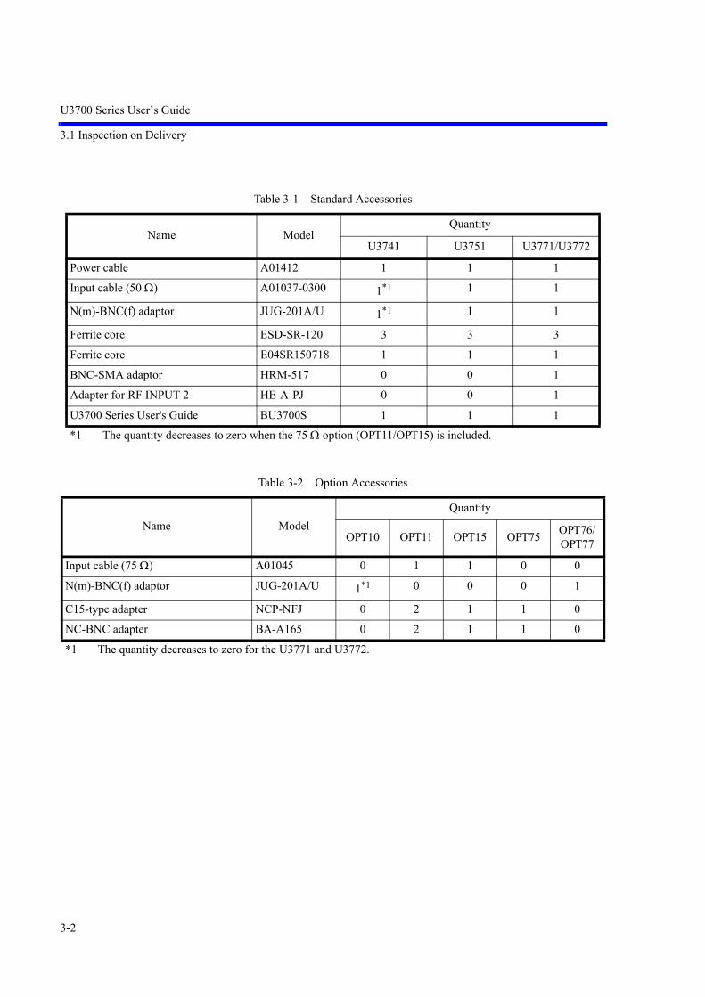
Table 3-1 Standard Accessories
Name ModelQuantity
U3741 U3751 U3771/U3772
Power cable A01412 1 1 1
Input cable (50 ) A01037-0300 1*1 1 1
N(m)-BNC(f) adaptor JUG-201A/U 1*1 1 1
Ferrite core ESD-SR-120 3 3 3
Ferrite core E04SR150718 1 1 1
BNC-SMA adaptor HRM-517 0 0 1
Adapter for RF INPUT 2 HE-A-PJ 0 0 1
U3700 Series User's Guide BU3700S 1 1 1
*1 The quantity decreases to zero when the 75 option (OPT11/OPT15) is included.
Table 3-2 Option Accessories
Name ModelQuantity
OPT10 OPT11 OPT15 OPT75 OPT76/OPT77
Input cable (75 ) A01045 0 1 1 0 0
N(m)-BNC(f) adaptor JUG-201A/U 1*1 0 0 0 1
C15-type adapter NCP-NFJ 0 2 1 1 0
NC-BNC adapter BA-A165 0 2 1 1 0
*1 The quantity decreases to zero for the U3771 and U3772.

U3700 Series User’s Guide
3.2 Locating This Instrument
3-3
3.2 Locating This Instrument
This section describes the installation environment in which this instrument runs successfully.
3.2.1 Operating Environment
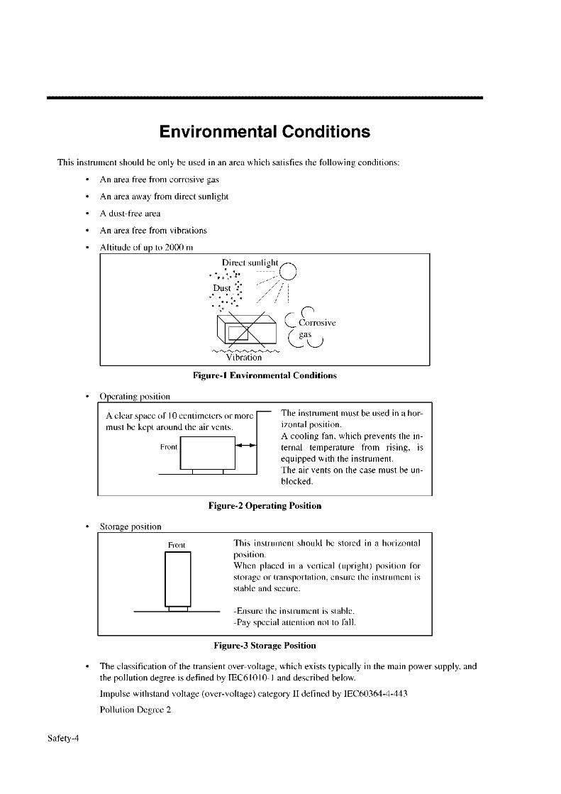
Install this instrument in an environment in which the following conditions are satisfied.
• Ambient temperature: 0C to +50C (operating temperature)-20C to +60C (storage temperature)
• Relative humidity: 85 percent or less with no condensation
• An area free from corrosive gas
• An area away from direct sunlight
• A dust-free area
• An area free from vibrations
• A low noise areaAlthough this instrument has been designed to withstand a certain amount of noise from the AC power line, it should be used in a low noise area.Use a noise cut filter if ambient noise is unavoidable.
• An area in which the airflow is not obstructedThere is an exhaust-cooling fan and exhaust vents on both sides of this instrument. Do not obstruct the fan and vents. If there is insufficient airflow around the vents, the internal temperature will rise and the instrument may operate incorrectly. Keep a space of 10 centimeters between the side panel and the wall. Do not use this instrument on its side.
Figure 3-1 Operating Environment
Vibration
Direct sunlight
Corrosivegas
• Avoid operating in these areas. • Use a noise cut filter if noise is unavoidableon the AC power line.
• Keep a space of 10 centimeters fromthe wall.
Dust
• Do not use this instrument on its side.
Side
Side
Line Filter

U3700 Series User’s Guide
3.3 Power Supply
3-4
3.3 Power Supply
This instrument can use the following three types of power sources.
• An AC Power SupplyAutomatically switches the power supply voltage between 100 V AC and 200 V AC.
• A batteryUse an external battery pack (A870008).Recommended battery pack: DIONIC90 (Manufactured by Anton Bauer Inc.)
• An external DC power supplyUse an external DC power cable (A114020).
CAUTION: Connect this instrument to an AC power supply, DC power supply, or battery.
3.3.1 Using the AC Power Supply
This section describes power requirements and how to connect the power cable.
3.3.1.1 AC Power Requirements
The AC power requirements of this instrument are shown in Table 3-3. Check that the power supply, whichis supplied to this instrument, satisfies the conditions shown in Table 3-3.
WARNING: Make sure the power supply, which is supplied to this instrument, satisfies the power requirements.If the power requirements are not satisfied, this instrument may be damaged.
Table 3-3 Power Requirements
100 V AC 200 V AC Remarks
Power supply voltage range 90 V - 132 V 198 V - 264 V Automatically switches the input voltage between 100 V AC and 200 V AC.
Frequency range 47 Hz - 63 Hz
Power consumption 100 VA or less

U3700 Series User’s Guide
3.3.1 Using the AC Power Supply
3-5
3.3.1.2 Connecting the Power Cable
This instrument includes a three-core power cable with a grounding conductor. To prevent accidentscaused by electric shocks, use the included power cable and securely connect to the ground through athree-pin power outlet.
1. Check that the included power cable is not damaged.
WARNING: Never use a damaged power cable. You may receive an electrical shock.
2. Connect the AC power connector on the rear panel of this instrument to a three-pin power outlet that has a protected ground terminal by using the included powercable (See Figure 3-2).
Figure 3-2 Connecting the Power Cable
WARNING:
• Use a suitable power cable for the power supply voltage. Use a power cable that complies with the safetystandards in your country (Refer to "Safety Summary").
• To prevent any danger of electrical shock, connect the power cable to a three-pin power outlet that is con-nected to a protected ground terminal. The instrument will not be grounded if an extension cord, whichdoes not include a protected ground terminal, is used.
AC power connector

U3700 Series User’s Guide
3.3.2 Using a Battery
3-6
3.3.2 Using a Battery
The U3700 series can use a battery as a power source.
An Anton Bauer's battery pack can be used in the U3700 series. The DIONIC 90 compact lithium-ion battery pack is recommended.
The DIONIC 90 battery pack specifications
Capacity: 90 WH Nominal
Output voltage:14.4 V
Weight: Approx. 0.7 kg
Dimensions: 133 89 54 mm
For more information, refer to the battery pack operation manual.
INFORMATION:Runtime (hours) U3741: 3 hoursU3751: 2.5 hoursU3771/72: 2 hours
NOTE: The battery life varies depending on the usage situation.If using a battery stored over the long term, check the runtime in advance.
3.3.2.1 Battery Mount System
The QR Gold Mount System, which is included in professional video cameras worldwide, is included inthis instrument.
1. How to remove and replace the battery packAlign the side of the battery pack that contains the connector with the battery mount on the rear panelof this instrument and push it in and down. The battery is attached when a “click” is heard.Turn off the power supply of this instrument when detaching the battery. To detach the battery, lift thebattery up while pushing the eject button on the battery mount.

U3700 Series User’s Guide
3.3.2 Using a Battery
3-7
2. Locking the Eject buttonThe slide switch to lock the Eject button is located on the right side of the battery mount (lower sideof the Eject button).The Eject button is locked by setting the slide switch to upper side.Set the slideswitch to the lower side and release the lock before the battery pack is attached or detached.
3.3.2.2 Charging the Battery
This instrument cannot charge the external battery pack.Use a suitable battery charger for the battery pack.
• For the DIONIC 90The TITAN TWIN charger (A870009) is recommended. When the TITAN TWIN charger is used, the charging time is approximately 5.5 hours.
Slide switch for locking
Eject Button
Locking

U3700 Series User’s Guide
3.3.3 Using the External DC Power Supply
3-8
3.3.3 Using the External DC Power Supply
3.3.3.1 DC Power Requirements
3.3.3.2 Connecting the DC Power Cable
1. Remove the AC power cable and detach the battery.
2. Connect an A114020 (Sold separately) external DC power cable to the DC power supply input con-nector on the rear panel.
CAUTION: Do not reverse the polarity of the DC power supply.
3. To remove the DC power cable, turn off the power supply of this instrument and remove the externalDC power cable while pushing the button on the cable connector.
DC power supply Requirements
Power supply voltage range +11 V to +17 V
Power consumption 70 W or less
DC power supply input connector (XLR 4 pins)
[Connector pin location]Pin number 1: GNDPin number 2: N.CPin number 3: N.CPin number 4: + terminal
1
2 3
4

U3700 Series User’s Guide
3.4 Caution when Connecting Peripherals
3-9
3.4 Caution when Connecting Peripherals
Use shielded cables when connecting peripherals to the USB and LAN connectors on this instrument.
Attach the included ferrite core (ESD-SR-120) to the cable.
Figure 3-3 Attachment of a Ferrite Core 1
When connecting an earphone to the PHONE connector, attach the included ferrite core (E04SR150718) tothe earphone cable.
Figure 3-4 Attachment of a Ferrite Core 2

U3700 Series User’s Guide
3.5 Checking Operations
3-10
3.5 Checking Operations
This section describes how to check operations by using the calibration function of this instrument. Checkthat this instrument operates correctly by following the procedure below.
Starting this instrument
1. Connect the power cable according to "3.3.1.2 Connecting the Power Cable".
2. Turn on the AC power switch on the rear panel.
3. Three seconds after turning on the AC power switch on the rear panel, press thepower switch on the front panel to turn on the instrument.The power supply and the green power light turn on.
Figure 3-5 POWER Switch
4. The system boots up and the program starts.

U3700 Series User’s Guide
3.5 Checking Operations
3-11
5. The result of the self-diagnostics and the initial screen are displayed.The initial screen display may differ from Figure 3-6 depending on the status ofthe settings when the power supply was last turned off.
Figure 3-6 Initial Screen
MEMO: If any error message is displayed, refer to “9. MAINTENANCE”.

U3700 Series User’s Guide
3.5 Checking Operations
3-12
Running calibration
6. Connect as shown in Figure 3-7 by using the included N-BNC adaptor and inputcable (A01037-300).
Figure 3-7 Connecting the CAL Signal
IMPORTANT: Perform calibration after allowing a warm up time of at least 5 minutes.For more information on how to perform autocalibration, refer to“4.3.1 Calibration”.
7. Press the SYSTEM key of this instrument and select Calibration from the softmenu.
8. Select Calibrate ALL on the next soft menu. It takes approximately two minutes to complete the autocalibration.
9. Check that no error message is displayed at the end of the calibration.
MEMO: If any error message is displayed, refer to “9. MAINTENANCE”.
Turning off the power supply
10. Press the power switch on the front panel.The power supply and the power light turn off.

U3700 Series User’s Guide
4. INSTRUMENT CONFIGURATION AND BASIC OPERATIONS
4-1
4. INSTRUMENT CONFIGURATION AND BASIC OPERATIONS
This chapter describes the functions of each part on the panels and screen, and describes the basic operationsof this instrument by using measurement examples.
4.1 Panel and Screen Descriptions
This section describes the names and functions of each part on the front panel, screen, and rear panel.
4.1.1 Names and Functions of Each Part on the Front Panel
This section describes the names and functions of each part on the front panel.
Figure 4-1 Front Panel
1. POWER switch with lamp Switches the power supply between ON and OFF.The lamp turns on while the power turns on
2. Extended function key block The keys in this block set the extended functions.
3. PHONE connector 8-ohm earphone terminal for demodulated AM/FM audio signals.
4. USB connector Enables a memory device or printer to be connected.
5. Color LCD Displays measurement data or setting conditions.
6. Soft key block The keys in this block select items from the soft menu on the dis-play.
1 2 4 5 6 7
8
9
3

U3700 Series User’s Guide
4.1.1 Names and Functions of Each Part on the Front Panel
4-2
7. Input connector lamp Indicates the input connector is enabled.U3741/U3751: Only RF INPUT 1 is enabled.
8. Input and output connectors block The connectors in this block are used in measurements.
9. Operation key block The keys in this block are used for changing settings.
Figure 4-2 Extended Function Key Block
1. Key lock key with lamp Locks the key input. Toggles the key lock between ON and OFF. The lamp turns on while the key input is locked.
2. LOCAL key Cancels the remote control function.
REMOTE lamp The lamp turns on when the instrument is in the remote state.
3. SYSTEM setting Sets the operational conditions of an interface.
Preset key Initializes the settings of this instrument.
4. APPLICATION key Switches between the applications of this instrument.
5. FILE key Loads and saves data.
6. COPY key Outputs screen data.
7. HELP key Explains the soft menu.
NOTE: HELP is loaded and functions when the HELP key ispressed at the first time after the power is turned on.
8. SHIFT key with lamp Sets the shift mode which allows the functions indicated by thegreen font to be selected. Turns on while the shift mode is set.
1
2
3
4
5
6
7
8

U3700 Series User’s Guide
4.1.1 Names and Functions of Each Part on the Front Panel
4-3
Figure 4-3 Soft Key Block
1. CLEAR key Cancels data entry mode.
2. Soft menu key The soft key 1 to 7 correspond with the soft menu 1 to 7 indicatedto the left respectively. Press the soft key to select the soft menu.
3. RETURN key Returns to the previous soft menu.
1
2
3

U3700 Series User’s Guide
4.1.1 Names and Functions of Each Part on the Front Panel
4-4
Figure 4-4 Input and Output Connectors Block
1. CAL OUT connector Outputs the calibration signal.
2. TG OUTPUT connector Outputs the tracking generator signal. (Option)
3. RF INPUT 1 connector Input the signal to be measured.Measurement frequency range: U3741: 9 kHz - 3 GHzU3751/U3771/U3772: 9 kHz - 8 GHz
4. RF INPUT 2 connector Input the signal to be measured.Measurement frequency rangeU3771: 10 MHz - 31.8 GHzU3772: 10 MHz - 43 GHz
CAUTION:
1. Do not apply an RF power or DC voltage that exceeds the limited value to the INPUT and OUTPUT con-nectors. Be careful of static electricity. Internal circuit components such as the input attenuator and mixer maybe damaged.
2. The precision microwave connector is used as the RF INPUT 2 connector.This connector is compatible with the K connector (K connector is a trademark of Anritsu Corporation.)and can be connected to a common SMA connector.Be careful when handling this connector because the connector is delicate and is damaged easily.Use the included adapter (HE-A-PJ) if the connection and disconnection to this connector are per-formed frequently.
3. For the 75 option (OPT15 and OPT75), input and output connectors are changed to 75 type con-nectors. If a 50 cable or connector is connected to a 75 connector, the center contact of the 75 connectormay be damaged. Verify that cables and connectors, which are used, are 75 type.
1 2 34
U3741: For the 75 option (OPT15 and OPT75)
U3700 Series User’s Guide
4.1.1 Names and Functions of Each Part on the Front Panel
4-5
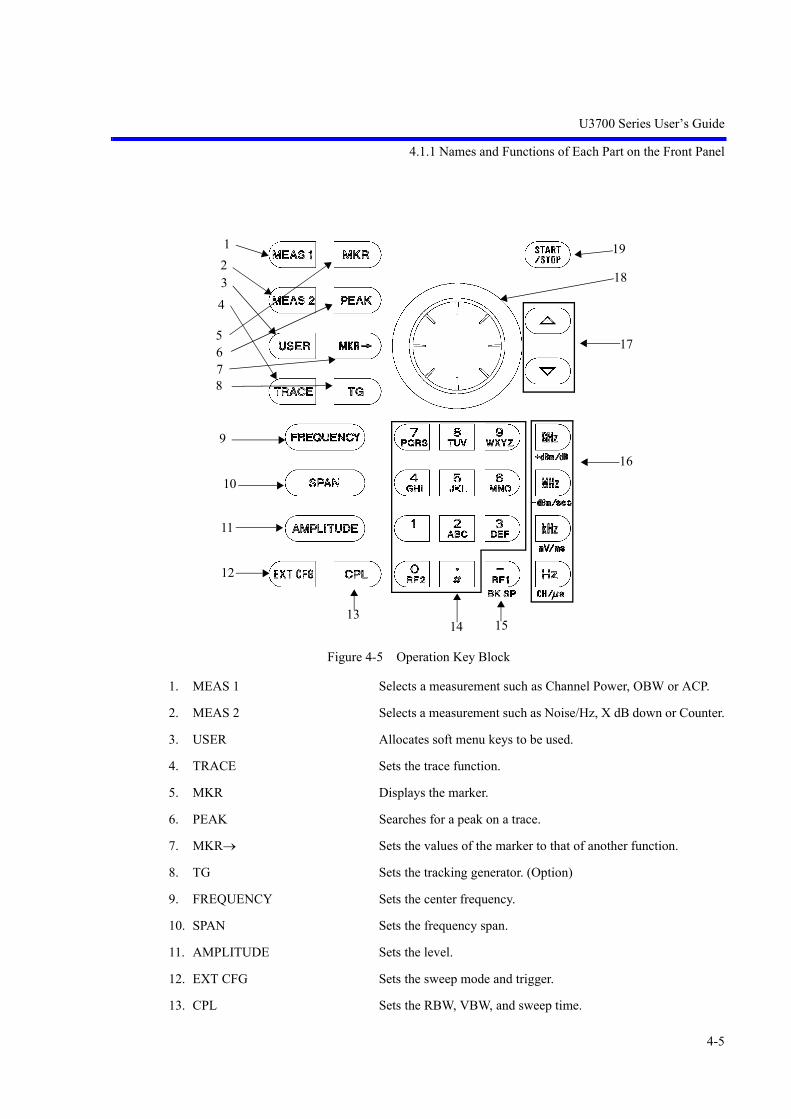
Figure 4-5 Operation Key Block
1. MEAS 1 Selects a measurement such as Channel Power, OBW or ACP.
2. MEAS 2 Selects a measurement such as Noise/Hz, X dB down or Counter.
3. USER Allocates soft menu keys to be used.
4. TRACE Sets the trace function.
5. MKR Displays the marker.
6. PEAK Searches for a peak on a trace.
7. MKR Sets the values of the marker to that of another function.
8. TG Sets the tracking generator. (Option)
9. FREQUENCY Sets the center frequency.
10. SPAN Sets the frequency span.
11. AMPLITUDE Sets the level.
12. EXT CFG Sets the sweep mode and trigger.
13. CPL Sets the RBW, VBW, and sweep time.
123
4
5678
9
11
12
1314 15
16
17
18
19
10

U3700 Series User’s Guide
4.1.1 Names and Functions of Each Part on the Front Panel
4-6
14. Keypad There are numeric keys (0 to 9) and decimal point key.
15. - (Backspace)key Enters the minus sign and corrects entered data.
16. Unit key Selects a unit and determines the entered value.
GHz Sets a unit of GHz, +dBm, or dB.
MHz Sets a unit of MHz, -dBm, sec, V, or W.
kHz Sets a unit of kHz, mV, msec, or mW.
Hz Sets a unit of Hz, sec, CH, V, or W.
Can also be used as the ENTER key
17. Step key Enters data at each step.
18. Data knob Fine tunes the entered data.
19. START/STOP key Starts or stops the sweep.

U3700 Series User’s Guide
4.1.2 Names and Functions of Each Part on the Screen
4-7
4.1.2 Names and Functions of Each Part on the Screen
This section describes the names and functions of each part on the screen of this instrument.
Figure 4-6 Screen Display
1. Reference level Displays the reference level setting value.
2. Amplitude scale in log mode or linear modeDisplays the amplitude scale setting in log mode.
3. Active function Displays the function enabled by the keypad or data knob.
4. Level scale Displays the level scale.
5. Center frequency or start frequencyDisplays the center frequency or start frequency.
6. Resolution bandwidth (RBW) Displays the resolution bandwidth setting value.Displays the font color of RBW in green if RBW is set in the man-ual mode.
7. User’s title Displays the description of the details of the measured data.
8. Video bandwidth (VBW) Displays the video bandwidth setting value.Displays the font color of VBW in green if VBW is set in the man-ual mode.
67
8 9
34
5
25
12
1716
151413121110
1921 20222324 18

U3700 Series User’s Guide
4.1.2 Names and Functions of Each Part on the Screen
4-8
9. Number of times averaging is performedDisplays the set and current number of times averaging is per-formed.
10. Sweep time Displays the sweep time setting value. Displays the font color of SWP in green if SWP is set in the man-ual mode.
11. Frequency span or stop frequency Displays the frequency span or stop frequency.
12. High-sensitivity (Hi-sensitivity) Displays HiS while the preamplifier is set to On.
13. RF attenuator Displays the attenuator setting value. Displays the font color of ATT in green if ATT is set in the manualmode.
14. UNCAL message Displays UNCAL while the manual settings are inappropriate.
15. Image Suppression Displays IS while the image suppression function is set to On.
16. Level offset Displays LOF while the reference offset is set to On.
17. Frequency offset Displays FOF while the frequency offset is set to On.
18. Marker area Displays the marker frequency (time) and level.
19. Date Displays the current date and time.
20. Measurement function display Displays the currently performed measurement function.
21. Trace and trace detector Displays the selected trace mode and trace detector mode.The trace with * displayed at the beginning is the active trace.For a display of two traces or more, the trace with * is displayedat the front.
22. Trace point Displays "501 pts" while the number of trace points is set to 501points.
23. Input impedance 75 Displays "75 " while the Input Impedance is set to 75 .
24. External reference signal Displays Ref EX1 while the external reference signal is selected.
25. R3162/R3131 mode ON R3131 mode: Displays "*" while the R3131 mode is set to ON inU3741.
R3162 mode: Displays "*" while the R3162 mode is set to ON inU3751/U3771/U3772.

U3700 Series User’s Guide
4.1.3 Names and Functions of Each Part on the Rear Panel
4-9
4.1.3 Names and Functions of Each Part on the Rear Panel
This section describes the names and functions of each part on the rear panel.
Figure 4-7 Rear Panel
1. AC power connector Connects this instrument to the AC power supply by using theincluded power cable.
2. AC power switch Switches the AC power ON and OFF.
3. EXT TRIG connector Inputs the external trigger signal (TTL level).
4. EXT REF connector Inputs the external reference signal.
5. USB A connector Enables a memory device or printer to be connected.
6. LAN connector For 10BaseT-specific LAN connector
7. VIDEO connector Connects to the monitor for VGA specification.
8. IF OUT connector Outputs an IF signal of 21.4 MHz.
9. DC INPUT connector Connects to the external DC power supply.
10. Battery mount The Anton Bauer’s battery pack can be used.
11. GP-IB connector Connects to the external controller when the remote-control isused through the GPIB interface.
1 2 3 4 5 6
8
7
9
10
11

U3700 Series User’s Guide
4.2 Basic Operation
4-10
4.2 Basic Operation
This section describes the menu operation, data entry, and usage of the basic measurement functions.
4.2.1 Menu Operation and Data Entry
Panel keys and soft menus are used to operate this instrument.
Press a panel key to display its menu to the right of the screen. Certain panel keys such as the LOCAL keydo not display a soft menu.
The menu items are arranged according to the soft keys.
The number of the menu item accords with the number of the related soft key.
Press a soft key to select the related menu.
Certain soft keys display another menu.
The following describes the functions of the panel key and soft key.
1. Selecting a menuTo set the measurement conditions, press the panel key and select the menu.Press AMPLITUDE.The reference level setting value is displayed in the active function display area and the followingLevel menu is displayed to the right of the screen.
1 Ref Level
2 ATT
3 dB/div
4 Vertical Scale LIN/LOG
5 Units
6 Slide Screen ON/OFF
7 More 1/2
The frame of the 1 Ref Level menu is displayed in red. This red frame menu means that data can beentered.
2. Data entryIf the set value is displayed in the active function display area, it can be changed by using keypad,step key, or data knob.• Data entry by using the keypad
Enter data by using the keypad, decimal point key, BK SP (backspace) key, and minus (-) key.If any wrong numbers are entered by using the keypad, use the BK SP to delete a character tothe left and enter the correct number. If no data is entered and BK SP is pressed, “- (minus)” isentered.After entering data, press the unit key (ENTER) to complete the entry.If any other panel key is pressed before the unit key is pressed, any entered data becomes invalid.
Example: Set the reference level to -20 dBm by using the keypad.Press -, 2, 0, GHz(+dBM) or 2, 0, MHz(-dBM).

U3700 Series User’s Guide
4.2.1 Menu Operation and Data Entry
4-11
• Data entry by using the step key
The step key enters data in the defined step size. Pressing decreases data and pressing increase data.
Example: Set the reference level to 0.0 dBm by using the step key.Press the step key . The reference level is set to -10.0 dBm. Press the stepkey again to set to 0.0 dBm.
• Data entry by using the data knobThe data knob enters data in the determined display resolution. The data knob is available forthe fine adjustment of the entry data.
Example: Set the reference level to 0.5 dBm by using the data knob.Rotating the data knob in the clockwise direction increases the reference levelin steps of 0.1 dBm. Rotate the data knob until the display of the active func-tion display area shows 0.5 dBm.Rotating the data knob in the counterclockwise direction decreases the refer-ence level in steps of 0.1 dBm.
• ACTIVE OFFPressing the CLEAR key hides the active function display area.Data cannot be entered if the active function display area is hidden.To redisplay the active function display area, press a panel key or soft key.
3. Menu layer
Certain soft menus have at the right end and the sub menu is displayed by pressing the soft key.Certain soft menus such as ON/OFF or AUTO/MNL switch the setting by pressing the soft key.Press MKR. The following Marker menu is displayed.
1 Select Marker
2 Marker ON/OFF
3 Marker Trace A/B/C
4 Delta Mode
5 Peak Menu
6 Clear All
7 More 1/2
• Switching the settingIf a menu includes a dual-state button such as ON/OFF or AUTO/MNL, the state can beswitched by pressing the soft key. The selected setting is displayed convexly.The non-selected setting is displayed concavely.
Example: Press 2 Marker ON/OFF.The setting is turned OFF and the markers disappear.Press 2 Marker ON/OFF again to turn the setting ON and the markers re-ap-pear.
• Sub menu display
Pressing a soft key, which has to the right of the menu, displays a sub menu.
Example: Press 4 Delta Mode . The following Peak menu is displayed.1 Delta ON/OFF

U3700 Series User’s Guide
4.2.1 Menu Operation and Data Entry
4-12
• RETURNPress RETURN to return to the previous menu from the sub menu.
4. Using SHIFTThe SHIFT key is used for selecting functions, which are indicated in green on the key.These functions are described below.• PRESET Returns to the initial settings.• ROOT Returns the soft menu to the top menu.• RF1 Selects RF INPUT 1. (U3771/U3772)• RF2 Selects RF INPUT 2. (U3771/U3772)
To perform the function, which is written on the key in green, press the SHIFT key and then presseach key.Pressing the SHIFT key turns on its LED and the shift mode is available.Press the SHIFT key again to cancel the shift mode. The green LED turns off and the shift mode isunavailable.Other keysNothing is printed on these keys, but they have the functions shown below.• USER Sets and cancels the USER menu.• COPY Displays the Copy menu.• Select Marker Returns one selected marker number.
5. Displaying a dialog boxPressing certain soft keys displays a dialog box.• Selecting items Select the horizontal items by using the data knob and select the vertical items
by using the step keys.• Entering numeric values
Enter values by using the keypad and unit key.• Determining the setting
Press the unit key (ENTER) to determine.

U3700 Series User’s Guide
4.3 Basic Measurement
4-13
4.3 Basic Measurement
This section uses the following measurement examples to describes basic measurement procedures whichwill allow the user to become familiar with the operation of this instrument.
4.3.1 Calibration
4.3.2 Displaying Spectrum and Operating Markers
4.3.3 How to Cancel the UNCAL Message
4.3.4 Identifying an Image Signal
4.3.5 Hard Copy Output
4.3.1 Calibration
Correcting the measurement by using the calibration factor, which is acquired from the calibration, canincrease the measurement accuracy.
Calibration items
1. Total GainMeasuring the calibration signal of -20 dBm and acquiring the level difference
2. Step ATTMinimizing the level error when switching STEP ATT at 20 MHz
3. RBWOptimizing the RBW adjustment and minimizing the level error when switchingRBW
4. PBW(Noise power bandwidth)
IMPORTANT: Perform calibration after allowing a warm up time of 5 minutes or more.
Required equipment
This instrumentConversion adaptor: N (m)-BNC (f)Conversion adaptor: BNC (f)-SMA (m)Input cable: BNC (m)-BNC (m)

U3700 Series User’s Guide
4.3.1 Calibration
4-14
Turning on the power supply
1. Verify that the AC power switch on the rear panel is set to OFF.
2. Connect the included power cable to the AC power connector on the rear panel.
CAUTION: To prevent damage, do not supply a voltage and frequency, whichexceed the specified range, to this instrument.
3. Connect the power cable to an electrical outlet.
4. Turn on the AC power switch on the rear panel.After turning on the AC power switch, wait for three seconds or more
5. Turn on the power switch on the front panel.
MEMO: The display may be different depending on the state of the instrument whenthe power was last turned off.
NOTE: Before turning the power on, remove the USB memory key. Otherwise, the system does not start.
Initialization
Initializes the settings of this instrument.
6. Press SHIFT and SYSTEM(PRESET).Initial setting conditions are loaded.
Figure 4-8 Initial Setting Screen

U3700 Series User’s Guide
4.3.1 Calibration
4-15
Selecting the input connector
For the U3741 and U3751, only RF INPUT 1 can be used as the input connector.No need to select the input connector.
For the U3771 and U3772, select the input to be performed the calibration.
Press SHIFT and - (RF1).RF INPUT 1 is selected.Press SHIFT and 0 (RF2).RF INPUT 2 is selected.
The calibration of either RF INPUT 1 or RF INPUT 2 can be performed first.
The following describes the procedure in which the calibration of RF INPUT 1 is performed first.
Connecting the input signal
Connect the calibration signal.
7. Attach the N(m)-BNC(f) adaptor to the RF INPUT 1 connector on the frontpanel. Connect the included BNC (m)-BNC (m) input cable to the CAL OUTconnector on the front panel and the N(m)-BNC(f) adaptor.
Figure 4-9 Connecting the CAL Signal (RF INPUT 1 connector)
8. Press SYSTEM.
9. Press 6 Calibration on the soft key menu.The Calibration menu is displayed.

U3700 Series User’s Guide
4.3.1 Calibration
4-16
10. Press Calibrate All on the Calibration menu.Calibration starts.The following message is displayed if the calibration of RF INPUT 1 is complete.
First step of calibration completed.Connect the calibrator to RF2 connector.Then press OK to continue.
The calibration is canceled if Hz is pressed.To perform the calibration of RF INPUT 2, change the cable connection.
11. Attach the BNC(f)-SMA(m) adapter to the RF INPUT 2 connector on the frontpanel.Connect the included BNC(m)-BNC(m) input cable to the CAL OUT connectoron the front panel and the BNC(f)-SMA(m) adapter.
Figure 4-10 Connecting the CAL Signal (RF INPUT 2 connector)
12. Press and select OK.Press Hz to start the calibration.

U3700 Series User’s Guide
4.3.2 Displaying Spectrum and Operating Markers
4-17
4.3.2 Displaying Spectrum and Operating Markers
This section describes how to display spectrums and use markers by using the CAL signal of this instru-ment.
The level difference between the CAL signal and its second harmonics are measured as an example.
Required equipment
This instrumentConversion adaptor: N (m)-BNC (f)Input cable: BNC (m)-BNC (m)
Turning on the power supply
IMPORTANT: Use this instrument within a specified temperature range to performaccurate measurements. Perform calibration after allowing a warm uptime of 5 minutes or more.
1. Verify that the AC power switch on the rear panel is set to OFF.
2. Connect the included power cable to the AC power connector on the rear panel.
CAUTION: To prevent damage, do not supply a voltage and frequency, whichexceed the specified range, to this instrument.
3. Connect the power cable to an electrical outlet.
4. Turn on the AC power switch on the rear panel.After turning on the AC power switch, wait for three seconds or more.
5. Turn on the power switch on the front panel.
MEMO: The display may be different depending on the state of the instrument whenthe power was last turned off.
Initialization
Initialize the settings of this instrument.
6. Press SHIFT and SYSTEM(PRESET).Initial setting conditions are loaded.

U3700 Series User’s Guide
4.3.2 Displaying Spectrum and Operating Markers
4-18
Connecting the input signal
Connecting the calibration signal.
7. Attach the N(m)-BNC(f) adaptor to the INPUT connector on the front panel.Connect the included BNC (m)-BNC (m) input cable to the CAL OUT connectoron the front panel and the N(m)-BNC(f) adaptor.
Figure 4-11 Connecting the CAL Signal
Setting measurement conditions
Setting the measurement conditions to observe the input signal more easily.
After initialization, the center frequency can be set.
8. Press 3, 0, and MHz.The center frequency is set to 30 MHz.

U3700 Series User’s Guide
4.3.2 Displaying Spectrum and Operating Markers
4-19
Figure 4-12 Setting the Center Frequency
9. Press SPAN.The current frequency span is displayed in the active function display area andthe Span menu is displayed.
10. Press 4, 0, and MHz.The frequency span is set to 40 MHz.
11. Press AMPLITUDE.The current reference level is displayed in the active function display area and theLevel menu is displayed.
12. Press -, 1, 0, and GHz(dBm).The reference level is set to -10 dBm.
Figure 4-13 Completing the Setting of the measurement conditions

U3700 Series User’s Guide
4.3.2 Displaying Spectrum and Operating Markers
4-20
Displaying a marker on the peak
13. Press PEAK.The marker is displayed on the peak and the frequency (approximately 20 MHz)and level (approximately -20 dBm) of the marker are displayed in the marker area
Figure 4-14 Displaying the Peak Search
Displaying a delta marker
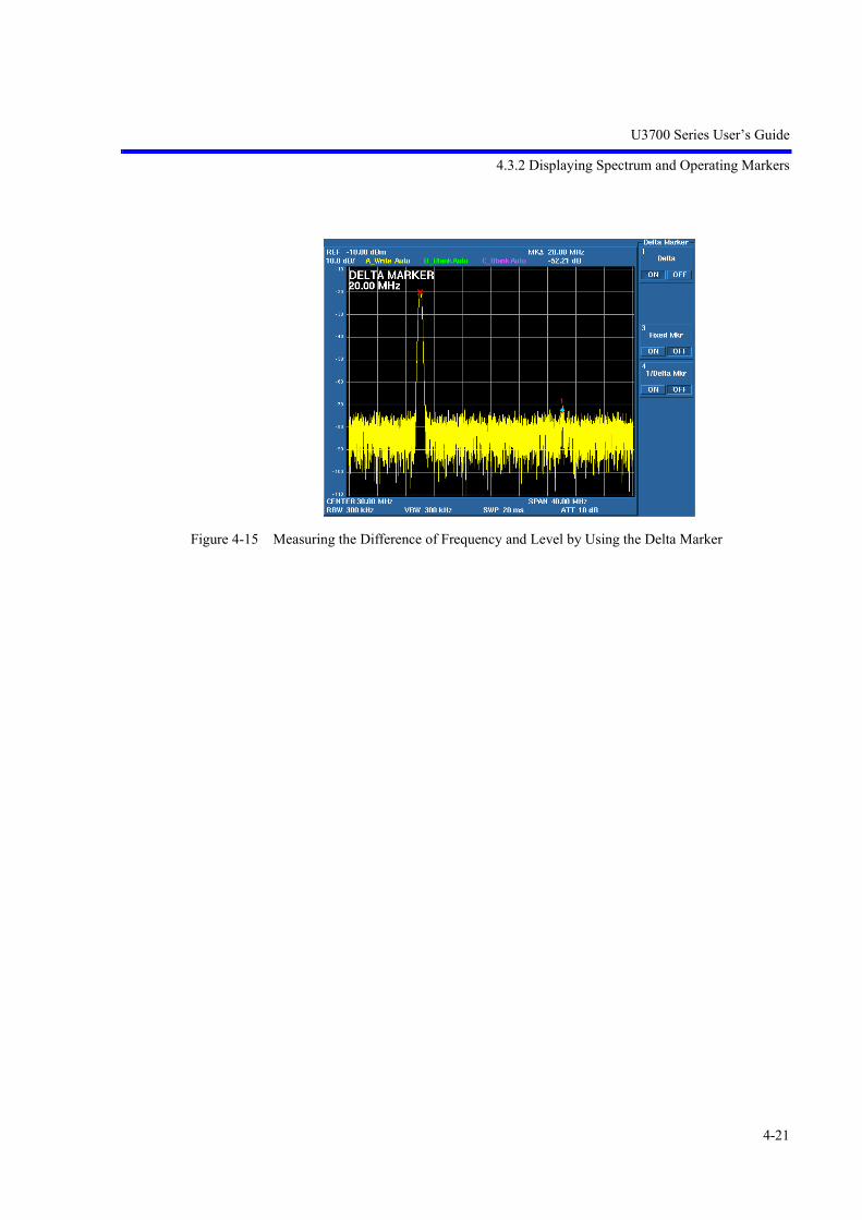
14. Press MKR.The Marker menu used for the marker function is displayed.Press 4 Delta Mode.Press 1 Delta ON/OFF.The delta marker is displayed and the frequency difference and level differencebetween the marker and delta marker are displayed in the marker area.MK 0 Hz0.00 dB
15. Press 2, 0, and MHz.The active marker is displayed on the second harmonics, which is 20 MHz awayfrom the CAL signal.The differences of frequency and level between two signals are displayed in themarker area.MK 20.00 MHz-52.21 dB
U3700 Series User’s Guide
4.3.2 Displaying Spectrum and Operating Markers
4-21
Figure 4-15 Measuring the Difference of Frequency and Level by Using the Delta Marker

U3700 Series User’s Guide
4.3.3 How to Cancel the UNCAL Message
4-22
4.3.3 How to Cancel the UNCAL Message
The setting among the resolution bandwidth (RBW), video bandwidth (VBW), frequency span (Span), andsweep time (Sweep Time) affect to each other.If the combination of these settings in the manual setting is inappropriate, the UNCAL message is dis-played at the bottom to the right of the scale. If the UNCAL message is displayed, the measurement levelaccuracy cannot be guaranteed.
Change the following settings to cancel the UNCAL message.
• Expand the resolution bandwidth (RBW).
• Expand the video bandwidth (VBW).
• Slow the sweep time (Sweep Time).
• If RBW or VBW cannot be changed, narrow the frequency span (Span).
IMPORTANT: Accurate measurement data cannot be acquired while the UNCAL message is displayed.
This section describes how to cancel the UNCAL message, which was generated because of the fast sweeptime, by changing the RBW setting.
Required instruments
This instrumentConversion adaptor: N (m)-BNC (f)Input cable: BNC (m)-BNC (m)
Turning on the power supply
IMPORTANT: Use this instrument within the specified temperature range to perform accurate measurements.Perform calibration after allowing a warm up time of 5 minutes or more.
1. Verify that the AC power switch on the rear panel is set to OFF.
2. Connect the included power cable to the AC power connector on the rear panel.
CAUTION: To prevent damage, do not supply a voltage and frequency, whichexceed the specified range, to this instrument.
3. Connect the power cable to an electrical outlet.
4. Turn on the AC power switch on the rear panel.After turning on the AC power switch, wait for three seconds or more.
5. Turn on the power switch on the front panel.
MEMO: The display may be different depending on the state of the instrument whenthe power was last turned off.

U3700 Series User’s Guide
4.3.3 How to Cancel the UNCAL Message
4-23
Initialization
Initialize the settings of this instrument.
6. Press SHIFT and SYSTEM(PRESET).Initial setting conditions are loaded.
Connecting the input signal
Connect the calibration signal.
7. Attach the N(m)-BNC(f) adaptor to the INPUT connector on the front panel.Connect the included BNC (m)-BNC (m) input cable to the CAL OUT connectoron the front panel and the N(m)-BNC(f) adaptor.
Figure 4-16 Connecting the CAL Signal
Setting measurement conditions
Set the measurement conditions to observe the input signal more easily.
8. Press FREQUENCY, 2, 0, and MHz.The center frequency is set to 20 MHz.
9. Press CPL, Sweep Time AUTO/MNL, 2, 0, and kHz (ms).The sweep time is set to 20 ms.
10. Press SPAN, 1, 0, and kHz.The span is set to 10 kHz.The RBW is automatically set to 300 Hz according to the span setting andUNCAL message is displayed.The sweep time setting of 20 msec is too fast for the set conditions.

U3700 Series User’s Guide
4.3.3 How to Cancel the UNCAL Message
4-24
Figure 4-17 Displaying the UNCAL Message
How to cancel the UNCAL message
11. Press CPL, RBW AUTO/MNL, 1, and kHz.Setting the RBW to 1 kHz cancels the UNCAL message because the sweep timeof 20 msec meets the set conditions.
Figure 4-18 Canceling the UNCAL Message
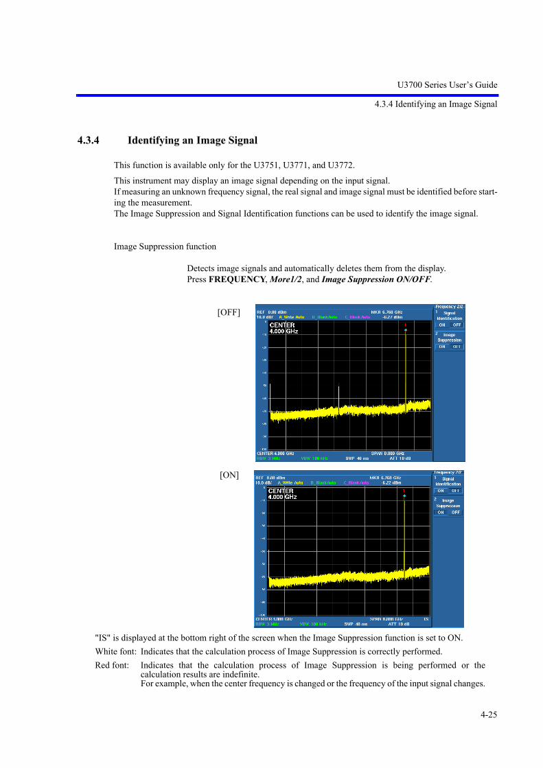
U3700 Series User’s Guide
4.3.4 Identifying an Image Signal
4-25
4.3.4 Identifying an Image Signal
This function is available only for the U3751, U3771, and U3772.
This instrument may display an image signal depending on the input signal.If measuring an unknown frequency signal, the real signal and image signal must be identified before start-ing the measurement.The Image Suppression and Signal Identification functions can be used to identify the image signal.
Image Suppression function
Detects image signals and automatically deletes them from the display.Press FREQUENCY, More1/2, and Image Suppression ON/OFF.
[OFF]
[ON]
"IS" is displayed at the bottom right of the screen when the Image Suppression function is set to ON.White font: Indicates that the calculation process of Image Suppression is correctly performed.Red font: Indicates that the calculation process of Image Suppression is being performed or the
calculation results are indefinite.For example, when the center frequency is changed or the frequency of the input signal changes.

U3700 Series User’s Guide
4.3.4 Identifying an Image Signal
4-26
Signal Identification function
The frequencies of Image signals are shifted and displayed in each sweep.The displayed frequencies of real signals do not change.Press FREQUENCY, More1/2, and Signal Identification ON/OFF.
Real signal Image signal

U3700 Series User’s Guide
4.3.5 Hard Copy Output
4-27
4.3.5 Hard Copy Output
4.3.5.1 Output to a Printer
Printer connection
When using a printer which is used for the first time,
1. Turn off the power of the printer and this instrument and connect the printer tothe USB connector on the front or rear panels of this instrument.
2. Turn on the power of the printer.
3. Turn on the power of this instrument.
Anytime after the second time the printer is used, the printer can be connected to thisinstrument even if the power of this instrument is turned on.
Output to a printer
1. Specify the printer as the output device in COPY Config.SYSTEM, More1/2, Copy Config, orSHIFT, COPY
Select PRT (printer) from the Copy Device menu.
2. Press the COPY key or Copy in the Copy menu to start printing.
Printers whose operation has been checked
MEMO: The printing time can be reduced by performing the following:
1. Start copying during a sweep stop.
2. Use White and Black for Color Pattern.
Manufacturer Model name
Epson PM-900C, PM-760C, PM-740C, PM-2200C, PM-G720, PX-V500
HP HP5650, HP6122, Deskjet5740, Deskjet6840, Photosmart7830
Canon iP4200

U3700 Series User’s Guide
4.3.5 Hard Copy Output
4-28
4.3.5.2 File Output to USB Memory
Connecting a USB memory device
1. Connect a memory device to a USB port on the front or rear panels of this instru-ment.
2. Press SYSTEM, More1/2, Copy Config, Screen Shot Config, and Media.A dialog box is displayed.Select a memory device by using the key and confirm it by using the Hz key.
3. Press the Media key.The dialog box closes.
File output
1. Selecting a file formatSelect the PNG or BMP format by pressing SYSTEM, More1/2, Copy Config,Screen Shot Config, and File Format PNG/BMP.
2. File nameCOPYxxx.BMP(PNG) is used as the file name.File number xxx is specified by Auto Inc Index and automatically increments by1 each time a file is saved when Auto Inc is set to ON.The file name COPY.BMP(PNG) is fixed when Auto Inc is set to OFF.
3. OutputImages on the screen can be saved to the USB memory device by pressing theCOPY key.

U3700 Series User’s Guide
4.3.5 Hard Copy Output
4-29
4. Time StampA time stamp (date and time), which uses the same format as the computer, isincluded in a file.The order in which files are saved can be checked by using thistime stamp.The date and time can be checked and set by panel operations or GPIB com-mands.Examples of GPIB commands:• Command to check the date and time
Date: SETDATE?Time: SETTIME?
• Command to set the date and timeDate: SETDATE yy/mm/ddTime: SETTIME hh/mm/ss
• ExampleSet the date to January 1, 2005.SETDATE 050101Set the time to 10:10.SETTIME 101000
NOTE: The USB memory key with a security function cannot be used.
Table 4-1 USB Memory Devices Whose Operation with this Instrument has Already Checked
Manufacturer Model name
BUFFALO RUF-C128ML/U2, RUF2-M128/256/1G, RUF2-E2GL-BL
HAGIWARA HUD-128PJ *
IO DATA EasyDisk EDP-128, TB-B128, TB-ST2G/K
LEXAR JumpDrive 128MB
SanDisk CruzerMini 128MB, SDCZ4-128-J65 *, SDCZ23-002G-J65N
ADTEC AD-UMX128MSB *
GREEN HOUSE GH-UFD128PLZ *
ELECOM MF-PU2128SV *, MF-AU202GSV
Princeton PFU-2JU/128/256/512/1G
Transcend TS2GJF160
* For the 256-MB type, the operation with this instrument has also been checked.

U3700 Series User’s Guide
4.3.6 Measuring by using the TG (OPT76/OPT77)
4-30
4.3.6 Measuring by using the TG (OPT76/OPT77)
Measures the characteristics of the bandpass filter, whose pass band is located near the frequency of 1900MHz.(Measuring the insertion loss and pass bandwidth of the filter)
Required equipment
This instrumentConversion adaptor: N(m)-BNC(f) 2Input cable: BNC(m)-BNC(m)
Turning on the power supply
IMPORTANT: Use this instrument within the specified temperature range to perform accurate measurements.Perform calibration after allowing a warm up time of 5 minutes or more.
1. Verify that the AC power switch on the rear panel is set to OFF.
2. Connect the included power cable to the AC power connector on the rear panel.
CAUTION: To prevent damage, do not supply a voltage and frequency, whichexceed the specified range, to this instrument.
3. Connect the power cable to an electrical outlet.
4. Turn on the AC power switch on the rear panel.After turning on the AC power switch, wait for three seconds or more.
5. Turn on the power switch on the front panel.
MEMO: The display may be different depending on the state of the instrument whenthe power was last turned off.
Initialization
Initialize the settings of this instrument.
6. Press SHIFT and SYSTEM(PRESET).Initial setting conditions are loaded.
7. Regarding U3771 and U3772, press SHIFT and - (RF1) to select RF INPUT 1.

U3700 Series User’s Guide
4.3.6 Measuring by using the TG (OPT76/OPT77)
4-31
Connecting the cable
1. Attach the N(m)-BNC(f) adapters to the RF INPUT 1 connector and the TGOUTPUT connector on the front panel and then connect the BNC(m)-BNC(m)cable to both connectors.
Figure 4-19 Connecting the TG Mesurement
Setting the measurement conditions to allow easier measurement of the input sig-nal.
2. Press FREQUENCY, 1, 9, 0, 0, and MHz.The center frequency is set to 1900 MHz.
3. Press SPAN, 2, 0, 0, and MHz.The frequency span is set to 200 kHz.
4. Press AMPLITUDE, dB/div, and 2dB/div.The level display scale is set to 2 dB/div.
5. Press TG, TG Level, 5, and MHz(-dBm).The output level of the tracking generator is set to -5 dBm.
6. Press TG ON/OFF to turn on the TG output.

U3700 Series User’s Guide
4.3.6 Measuring by using the TG (OPT76/OPT77)
4-32
Performing the normalization
MEMO: The frequency response errors of accessories used in the measurement such as cables and adapters canbe removed by performing the normalization and the accurate measurement can be performed.
1. Press Normalize.The TG Normz menu is displayed.
2. Press Reference Line ON/OFF, 5, and MHz(-dBm).The Reference Line position, at which the normalization is performed, is set to -5 dB.
3. Press Capture Normz Data.The normalization data is acquired based on the set Reference Line position.
4. Press Normalize Correction ON/OFF.The normalization is performed.
CAUTION: If the settings of the center frequency, frequency span, reference level,or level display scale are changed after the normalization is performed,the normalization subsequent to this change does not perform cor-rectly.Re-perform the normalization after changing the settings.
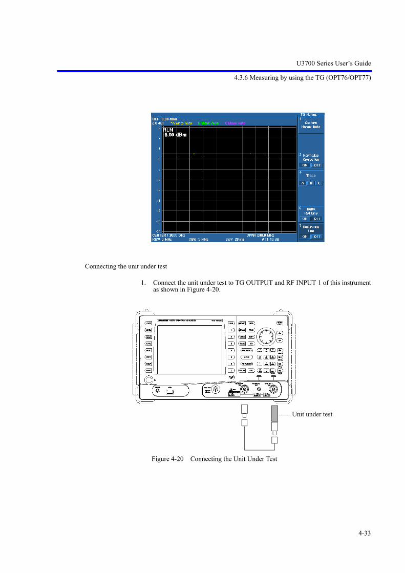
U3700 Series User’s Guide
4.3.6 Measuring by using the TG (OPT76/OPT77)
4-33
Connecting the unit under test
1. Connect the unit under test to TG OUTPUT and RF INPUT 1 of this instrumentas shown in Figure 4-20.
Figure 4-20 Connecting the Unit Under Test
Unit under test

U3700 Series User’s Guide
4.3.6 Measuring by using the TG (OPT76/OPT77)
4-34
CAUTION:
In the frequency response measurement by using the TG, the level measurementerror may be larger even if the UNCAL message is not displayed on the screen. Increase the sweep time until the displayed waveform does not change.The TG response affects the measurement accuracy in the following cases:
• The unit under test has high Q and sharp level change characteristics. (Forexample, crystal filter)
• The measurement is performed in the wide frequency span.
Measuring the insertion loss
1. Press Delta Ref Line ON/OFF. The MK value displays the level difference to the reference line.
2. Press PEAK. The marker level indicates the insertion loss of the filter.
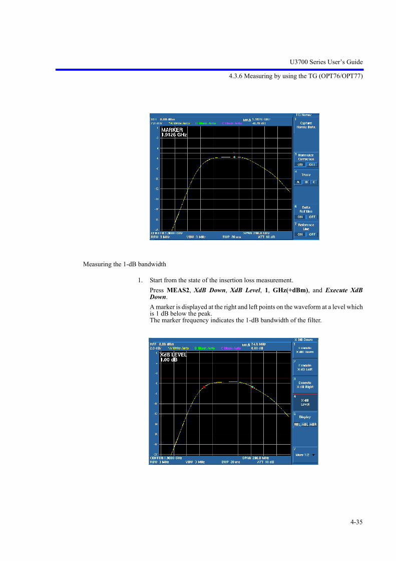
U3700 Series User’s Guide
4.3.6 Measuring by using the TG (OPT76/OPT77)
4-35
Measuring the 1-dB bandwidth
1. Start from the state of the insertion loss measurement. Press MEAS2, XdB Down, XdB Level, 1, GHz(+dBm), and Execute XdBDown.A marker is displayed at the right and left points on the waveform at a level whichis 1 dB below the peak.The marker frequency indicates the 1-dB bandwidth of the filter.

U3700 Series User’s Guide
4.3.7 USER Key
4-36
4.3.7 USER Key
A soft menu related to operation keys and extended function keys can be set to the USER key menu. The operability is improved by allocating functions, which are frequently-used or are located in a deepmultilayer menu, to the USER key menu.
How to set a function menu to the USER menu
1. Display a function menu, which is set to the USER menu, in the soft menu dis-play area.
2. Press SHIFT and then USER.
3. Press a menu key to be set.If canceling the setting, press any other operation key.
If setting an additional function menu to the USER menu, repeat the above procedure.
How to delete a function menu from the USER menu
1. Press USER to display the USER menu.
2. Press SHIFT and then USER.
3. Press a menu key to be deleted.
If deleting an additional soft key, repeat the above procedure.

U3700 Series User’s Guide
4.4 Measurement Examples
4-37
4.4 Measurement Examples
Descriptions regarding "Turning on the power" and "Initializing this instrument" are omitted from this chap-ter.
4.4.1 Using the Normalize Function and Level Correction Table
When a signal is measured by using a long measurement cable, the measurement level accuracy can beimproved by correcting the cable frequency loss.
Functions used in this measurement
1. TG option + Normalize function Cable loss measurement
2. Level correction table
Measuring the cable loss
1. Connect TG OUTPUT and RF INPUT 1 by using the input cable included withthis instrument.
2. Press FREQUENCY, 2, 0, MHz, SPAN, 1, MHz, TG, and TG ON/OFF (ON).The center frequency is set to 20 MHz, the frequency span is set to 1 MHz, andthe TG (option) is set to ON.
Long measurement cableDUT
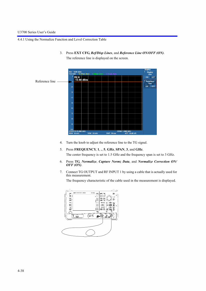
U3700 Series User’s Guide
4.4.1 Using the Normalize Function and Level Correction Table
4-38
3. Press EXT CFG, Ref/Disp Lines, and Reference Line ON/OFF (ON).The reference line is displayed on the screen.
4. Turn the knob to adjust the reference line to the TG signal.
5. Press FREQUENCY, 1, ., 5, GHz, SPAN, 3, and GHz.The center frequency is set to 1.5 GHz and the frequency span is set to 3 GHz.
6. Press TG, Normalize, Capture Normz Data, and Normalize Correction ON/OFF (ON).
7. Connect TG OUTPUT and RF INPUT 1 by using a cable that is actually used forthis measurement.The frequency characteristic of the cable used in the measurement is displayed.
Reference line

U3700 Series User’s Guide
4.4.1 Using the Normalize Function and Level Correction Table
4-39
8. Press MKR, Delta Mode, Delta ON/OFF (ON), Ref Object, and ReferenceLine.The marker delta mode is set.The marker value shows a cable loss based on a frequency of 20 MHz.
9. Move the marker and read a cable loss for each frequency.For this measurement, 10 frequency points from 300 MHz to 3 GHz are used.

U3700 Series User’s Guide
4.4.1 Using the Normalize Function and Level Correction Table
4-40
Creating the correction table
10. Press AMPLITUDE, More 1/2, and Edit Corr Factor.The Correction Factor Table is displayed.The cursor is positioned at the frequency setting text field of correction point 1.
11. Press 3, 0, 0, and MHz.The correction point 1 frequency is set to 300 MHz.The cursor moves to the level setting text field.
12. Press 0, ., 8, and GHz.The correction value of correction point 1 is set to 0.8 dB.The cursor moves to the frequency setting text field of correction point 2.
13. Repeat the above procedure and complete the correction table.

U3700 Series User’s Guide
4.4.1 Using the Normalize Function and Level Correction Table
4-41
Using the correction table
14. Press AMPLITUDE, More 1/2, and Correction Factor ON/OFF (ON).The displayed measurement value is corrected based on the correction table.
Correction Factor ONCorrection Factor OFF
The cable frequency loss is corrected.Cable loss: 3.13 dB at 3 GHz
Frequency: 2.1 GHz Measurement value: -12.9 dBm Frequency: 2.1 GHz Measurement value: -10.5 dBm

U3700 Series User’s Guide
4.4.1 Using the Normalize Function and Level Correction Table
4-42
Available range of the correction value
Up to 100 dB can be set as the correction value.The correction value of the first correction point is applied to frequencies from 0 Hzto the first correction point frequency. Correction values between points where correction values are set are obtained byusing a method of linear interpolation. The correction value of the last correction point is applied to frequencies following tothe last correction point frequency.
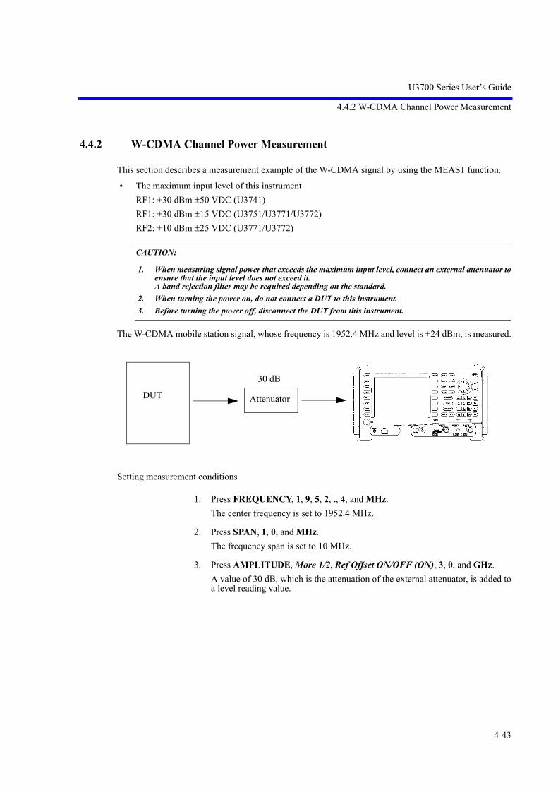
U3700 Series User’s Guide
4.4.2 W-CDMA Channel Power Measurement
4-43
4.4.2 W-CDMA Channel Power Measurement
This section describes a measurement example of the W-CDMA signal by using the MEAS1 function.
• The maximum input level of this instrument RF1: +30 dBm 50 VDC (U3741)RF1: +30 dBm 15 VDC (U3751/U3771/U3772)RF2: +10 dBm 25 VDC (U3771/U3772)
CAUTION:
1. When measuring signal power that exceeds the maximum input level, connect an external attenuator toensure that the input level does not exceed it. A band rejection filter may be required depending on the standard.
2. When turning the power on, do not connect a DUT to this instrument.
3. Before turning the power off, disconnect the DUT from this instrument.
The W-CDMA mobile station signal, whose frequency is 1952.4 MHz and level is +24 dBm, is measured.
Setting measurement conditions
1. Press FREQUENCY, 1, 9, 5, 2, ., 4, and MHz.The center frequency is set to 1952.4 MHz.
2. Press SPAN, 1, 0, and MHz.The frequency span is set to 10 MHz.
3. Press AMPLITUDE, More 1/2, Ref Offset ON/OFF (ON), 3, 0, and GHz.A value of 30 dB, which is the attenuation of the external attenuator, is added toa level reading value.
Attenuator
30 dB
DUT

U3700 Series User’s Guide
4.4.2 W-CDMA Channel Power Measurement
4-44
4. Press MEAS1 and Channel Power.A window that shows the measurement channel width is displayed at the centerof the screen.
5. Press Channel Width, 3, ., 8, 4, and MHz.The channel width is set to 3.84 MHz.
Measuring the channel power
6. Press Execute ON/OFF (ON).The channel power measurement starts.The detector is automatically set to RMS.
The measurement result is displayed.A display line that shows the channel power is displayed.
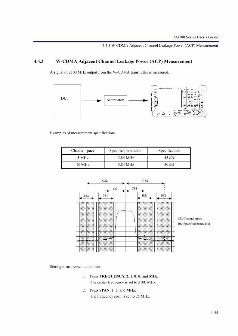
U3700 Series User’s Guide
4.4.3 W-CDMA Adjacent Channel Leakage Power (ACP) Measurement
4-45
4.4.3 W-CDMA Adjacent Channel Leakage Power (ACP) Measurement
A signal of 2100 MHz output from the W-CDMA transmitter is measured.
Examples of measurement specifications
Setting measurement conditions
1. Press FREQUENCY, 2, 1, 0, 0, and MHz.The center frequency is set to 2100 MHz.
2. Press SPAN, 2, 5, and MHz.The frequency span is set to 25 MHz.
Channel space Specified bandwidth Specification
5 MHz 3.84 MHz 45 dB
10 MHz 3.84 MHz 50 dB
AttenuatorDUT
CS: Channel spaceBS: Specified bandwidth
CS2
CS1
BS2 BS1
CS2
CS1
BS2BS1

U3700 Series User’s Guide
4.4.3 W-CDMA Adjacent Channel Leakage Power (ACP) Measurement
4-46
CAUTION:
Set the frequency span according to the following conditions.
• For Nyquist Filter OFF:
SPAN > 2*CS + BS
• For Nyquist Filter ON:
SPAN > 2*CS + (1 + Roll Off Factor)*Symbol Rate
3. Press AMPLITUDE, More 1/2, Ref Offset ON/OFF(ON), 3, 0, and GHz.A value of 30 dB, which is the attenuation of the external attenuator, is added toa level reading value.
4. Press MEAS1 and ACP.The ACP menu is displayed.
Setting the CS/BS table
5. Press Channel Definition.The CS/BS table is displayed. The cursor is positioned at the Channel Space 1 setting text field.
6. Press 5 and MHz.Channel Space 1 is set to 5 MHz. The cursor moves to the Channel Bandwidth 1 setting text field.
7. Press 3, ., 8, 4, and MHz.Channel Bandwidth 1 is set to 3.84 MHz. The cursor moves to the Channel Space 2 setting text field.
8. Press 1, 0, and MHz.Channel Space 1 is set to 10 MHz. The cursor moves to the Channel Bandwidth 2 setting text field.
9. Press 3, ., 8, 4, and MHz.Channel Bandwidth 2 is set to 3.84 MHz.
10. Press RETURN.

U3700 Series User’s Guide
4.4.3 W-CDMA Adjacent Channel Leakage Power (ACP) Measurement
4-47
Measuring the ACP
11. Press Execute ON/OFF (ON).The ACP measurement starts.The detector is automatically set to RMS.
Displaying the channel bandwidth
12. Press Config and Ch Windows ON/OFF (ON).The set channel bandwidth window is displayed on the screen.The frequency span must be set so that all channels are included in it.

U3700 Series User’s Guide
4.4.4 W-CDMA Spurious Measurement
4-48
4.4.4 W-CDMA Spurious Measurement
The spurious response is measured in frequency bands higher than 30 MHz.
Examples of measurement specifications
Setting measurement conditions
1. Press TRACE, Detector, and Posi.Detector is set to Posi to perform the spurious measurement.
2. Press MEAS1, Spurious, and Bands Definition.The Spurious Bands table is displayed.The cursor is positioned at the start frequency setting text field of frequency band1.
3. Press 3, 0, and MHz.The start frequency is set to 30 MHz and the cursor moves to the stop frequencysetting text field.
4. Press 1 and GHz.The stop frequency is set to 1 GHz and the cursor moves to the RBW selectionbutton from Auto and Manual.If selecting Auto, press Hz.If selecting Manual, turn the knob clockwise for one click to select the Manualbutton, and then press Hz.
Frequency range RBW Spurious level
9 kHz 150 kHz 1 kHz -13 dBm
150 kHz 30 MHz 10 kHz -13 dBm
30 MHz 1 GHz 100 kHz -13 dBm
1 GHz 12.75 GHz (*) 1 MHz -13 dBm
(*) In a frequency range from 1.8935 GHz to 1.9196 GHz and the 300-kHz RBW, the spurious level is -41 dBm or less.
AttenuatorDUT

U3700 Series User’s Guide
4.4.4 W-CDMA Spurious Measurement
4-49
5. Select Manual, and then press 1, 0, 0, and kHz.The RBW is set to Manual and 100 kHz.
6. Repeat the above procedure and set the VBW to Manual and 100 kHz, the SWPto Auto, the ATT to Manual and 20 dB, the Ref Level to 0 dBm, and the Preampto Off.The cursor moves to the limit value setting text field.
7. Press -, 1, 3, and GHz.The limit value is set to -13 dBm, and then the cursor moves to the start frequencysetting text field of the next frequency band.
8. Repeat the above procedure and complete the Spurious Bands table.
9. Press RETURN.The spurious measurement menu is displayed.

U3700 Series User’s Guide
4.4.4 W-CDMA Spurious Measurement
4-50
Measuring the spurious response
10. Press Execute ON/OFF (ON).The spurious response in each frequency band that changes after a sweep is mea-sured according to the measurement conditions set in the Spurious Bands table.Characters that indicate a frequency band, in which the spurious response isbeing measured, are displayed in yellow.If the measured value is equal to the set limit value or less, the judgment is PASS.If the measured value is more than the set limit value, the judgment is FAIL.
11. Press Results.Measurement results in each frequency band are displayed.

U3700 Series User’s Guide
4.4.5 CN Measurement in Terrestrial Digital Broadcasting
4-51
4.4.5 CN Measurement in Terrestrial Digital Broadcasting
The difference (CN ratio) between a carrier level (C) and noise level (N) in terrestrial digital broadcastingis measured.
When measuring the CN ratio, connect the 75- impedance converter (ZT-130NC) to the RF1 input con-nector of this instrument. Set the measurement unit to dBV.
Setting the measurement unit
1. Press AMPLITUDE, Units, and dBV.The measurement unit is set to dBV.
2. Press AMPLITUDE, More1/2, and Input Impedance 50/75 (75).The conversion loss of the 75- impedance converter (ZT-130NC) is correctedfor the measured value.
ZT-130NC70
50
TV signal

U3700 Series User’s Guide
4.4.5 CN Measurement in Terrestrial Digital Broadcasting
4-52
Measuring the carrier level (C)
Setting this instrument
Measurement mode: Channel power measurement functionCenter frequency: Center frequency in the channelSPAN 10 MHzRBW: 30 kHzVBW: 300 kHzMeasurement bandwidth: 5.6 MHz
(Channel power bandwidth)
Figure 4-21 Measurement Display for Channel Power
Procedure (Example for 27 channels)
1. Press FREQUENCY, 5, 5, 7, ., 1, 4, 2, 8, 5, 7, and MHz.The center frequency is set to 557.142857 MHz.
2. Press SPAN, 1, 0, and MHz.The frequency span is set to 10 MHz.

U3700 Series User’s Guide
4.4.5 CN Measurement in Terrestrial Digital Broadcasting
4-53
3. Press AMPLITUDE and then press to adjust a signal peak on the third scalefrom the top.
4. Press CPL, RBW AUTO/MNL, 3, 0, kHz, VBW AUTO/MNL, 3, 0, 0, and kHz.The RBW is set to 30 kHz and the VBW is set to 300 kHz.
5. Press MEAS1 and Channel Power.A window that shows the measurement channel width is displayed in the centerof the screen.
6. Press Channel Width, 5, ., 6, and MHz.The channel width is set to 5.6 MHz.

U3700 Series User’s Guide
4.4.5 CN Measurement in Terrestrial Digital Broadcasting
4-54
7. Press Execute ON/OFF (ON).The channel power measurement begins.
8. The measurement result is displayed in the Channel Power window.C = 58.33 dBV (Figure 4-21)
Measuring the noise level (N)
Setting this instrument
Measurement mode: Noise/Hz measurement functionMeasurement noise area frequency:
Noise that is adjacent to the measurement signal andnot affected by the signal
SPAN: 10 MHzRBW: 100 kHzVBW: 1 kHzMeasurement bandwidth: 5.6 MHz
(A value for the Noise/Hz conversion)Averaging count: 30 times
Figure 4-22 Measurement Display for Noise Power Converted into 5.6 MHz Bandwidth
Procedure
9. Press Execute ON/OFF (OFF).The channel power measurement is canceled.

U3700 Series User’s Guide
4.4.5 CN Measurement in Terrestrial Digital Broadcasting
4-55
10. Press CPL, RBW AUTO/MNL, 1, 0, 0, kHz, VBW AUTO/MNL, 1, and kHz.The RBW is set to 100 kHz and the VBW is set to 1 kHz.
11. Press MKR and then press to move the marker into a noise area.
12. Press TRACE, Calc, Power Average, Start/Stop (Start), Max Sweep Count, 3,0, and Hz (Enter).The Max Sweep Count is set to 30.
13. Press MEAS 2, Noise/Hz, 5, ., 6, and MHz.
14. Press dBV/Sqrt (Hz) ON/OFF (ON).The measurement begins.

U3700 Series User’s Guide
4.4.5 CN Measurement in Terrestrial Digital Broadcasting
4-56
15. The measurement result is displayed in the Noise-Marker 1 window.N = 34.26 dBV (Figure 4-22)
Calculating the CN ratio
The CN ratio can be obtained by calculating the values, which are measured from thecarrier (C) and noise (N) level measurements. (C: a value in step 8, N: a value in step 15)
CN ratio = C - N = 58.33 - 34.26 = 24.07 dB
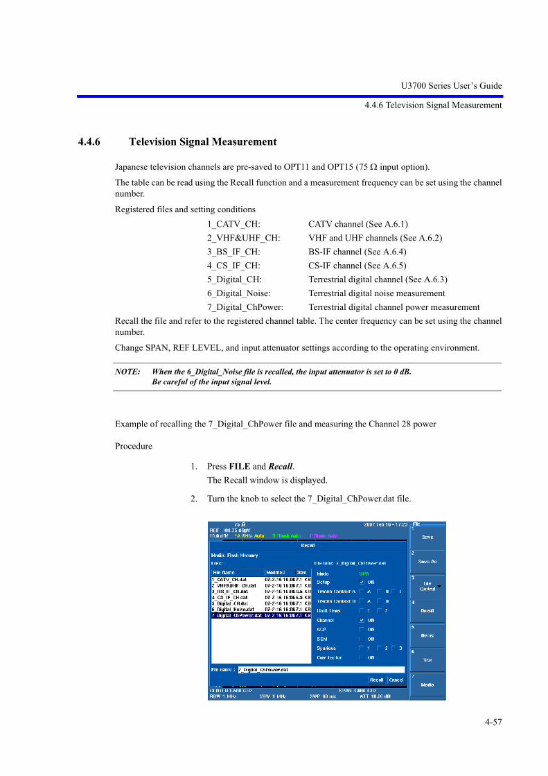
U3700 Series User’s Guide
4.4.6 Television Signal Measurement
4-57
4.4.6 Television Signal Measurement
Japanese television channels are pre-saved to OPT11 and OPT15 (75 input option).
The table can be read using the Recall function and a measurement frequency can be set using the channelnumber.
Registered files and setting conditions1_CATV_CH: CATV channel (See A.6.1)2_VHF&UHF_CH: VHF and UHF channels (See A.6.2)3_BS_IF_CH: BS-IF channel (See A.6.4)4_CS_IF_CH: CS-IF channel (See A.6.5)5_Digital_CH: Terrestrial digital channel (See A.6.3) 6_Digital_Noise: Terrestrial digital noise measurement7_Digital_ChPower: Terrestrial digital channel power measurement
Recall the file and refer to the registered channel table. The center frequency can be set using the channelnumber.
Change SPAN, REF LEVEL, and input attenuator settings according to the operating environment.
NOTE: When the 6_Digital_Noise file is recalled, the input attenuator is set to 0 dB. Be careful of the input signal level.
Example of recalling the 7_Digital_ChPower file and measuring the Channel 28 power
Procedure
1. Press FILE and Recall.The Recall window is displayed.
2. Turn the knob to select the 7_Digital_ChPower.dat file.

U3700 Series User’s Guide
4.4.6 Television Signal Measurement
4-58
3. Press Hz or .The 7_Digital_ChPower.dat file is determined as a file to be recalled.
4. Press Hz or .Select the Recall button.
5. Press Hz.The terrestrial digital broadcasting channel table and measurement conditions arerecalled and set.
6. Press FREQUENCY, 2, 8, and Hz.The center frequency is set to 563.14 MHz, that is for Channel 28.At the same time, the channel power measurement starts and then the measure-ment result is displayed.

U3700 Series User’s Guide
4.4.7 VSWR Measurement
4-59
4.4.7 VSWR Measurement
Reflection characteristics of an antenna and filter are measured by using the SWR bridge.
A return loss and VSWR at a marker point are displayed.
1. Connect the SWR bridge as shown in Figure 4-23 VSWR Measurement.
Figure 4-23 VSWR Measurement
2. Execute normalization without connecting a DUT to the TEST port of the SWRbridge. Set CENTER, SPAN, and REF in accordance with the DUT.Press TG, Reference Line ON/OFF(ON), 2, 0, and MHz. Set the reference line to -20 dBm.Press TG and TG ON/OFF(ON). Set the TG output to ON.Press Normalize, Capture Normz Data, and Normalize Correction ON/OFF(ON). Normalization is executed while the TEST port is open.
CAUTION: If a setting condition is changed after normalization is executed, re-execute normalization.
DUT
Out
TEST
In Bridge

U3700 Series User’s Guide
4.4.7 VSWR Measurement
4-60
3. Connect the DUT to the TEST port of the SWR bridge.Press VSWR ON/OFF(ON). A return loss and VSWR at the marker point are displayed.

U3700 Series User’s Guide
5. MENU MAP, FUNCTIONAL EXPLANATION
5-1
Operation Key Pages Operation Key Pages
5. MENU MAP, FUNCTIONAL EXPLANATION
This chapter describes the configurations and functions of the soft keys displayed on the touch screen.
Menu Index: This section can be used to refer to the keys in this chapter.
Menu Map: This section shows the menu configurations of the panel keys.
Functional Descriptions: This section describes the functions of the panel keys and soft keys.
5.1 Menu Index
%AM Meas ON/OFF .............................. 5-37, 5-40%OBW .................................................... 5-25, 5-300.5 dB/div ................................................ 5-62, 5-631 dB/div ................................................... 5-62, 5-631/Delta Mkr ON/OFF .............................. 5-47, 5-4810 dB/div ................................................. 5-62, 5-632 Channel ON/OFF ................................. 5-172 Channel Preset ..................................... 5-172 Channels Viewer .................................. 5-172 dB/div ................................................... 5-62, 5-635 dB/div ................................................... 5-62, 5-63A-BA ................................................... 5-43, 5-46A-BB ................................................... 5-43, 5-46A-BC ................................................... 5-43, 5-46ACP ......................................................... 5-25, 5-30A-DLA ................................................ 5-43, 5-46All Auto .................................................. 5-72, 5-73AMPLITUDE ......................................... 5-62Annotations ON/OFF .............................. 5-7, 5-9APPLI ..................................................... 5-17ATT ......................................................... 5-62ATT AUTO/MNL ................................... 5-62Attenuation 0 dB ..................................... 5-62Auto ........................................................ 5-72, 5-73Auto Inc Index ........................................ 5-8, 5-13Auto Inc ON/OFF ................................... 5-8, 5-13Auto name Index ..................................... 5-18, 5-20Auto Tune ............................................... 5-61Auto-name Radix .................................... 5-18, 5-20Average ................................................... 5-43, 5-44,
5-45Average Control ...................................... 5-25, 5-26,
5-27, 5-28, 5-29, 5-30, 5-32, 5-36, 5-38, 5-39
Average ONCE/SLIDE ........................... 5-25, 5-26,
5-27, 5-28, 5-29, 5-30, 5-32, 5-36, 5-38, 5-40, 5-43, 5-44, 5-45
Average PAUSE/CONT ......................... 5-36, 5-38, 5-40, 5-43, 5-44
Average Power ........................................ 5-25, 5-29Average START/STOP .......................... 5-36, 5-38,
5-39, 5-43, 5-44
Averaging ON/OFF ................................ 5-25, 5-26, 5-27, 5-28, 5-29, 5-30, 5-32
B-AA ................................................... 5-43, 5-46B-AB ................................................... 5-43, 5-46B-AC ................................................... 5-43, 5-46Bands Definition ..................................... 5-26, 5-33,
5-34B-DLB ................................................ 5-43, 5-46Black and White ...................................... 5-8, 5-12Blank ....................................................... 5-43, 5-44Calc ......................................................... 5-43, 5-44Calibrate ALL ......................................... 5-7, 5-11Calibration .............................................. 5-7, 5-11Calibration Corrections ON/OFF ............ 5-7, 5-11Calibration F Int Ref ............................... 5-7, 5-11Capture Normz Data ............................... 5-55Carrier Bandwidth ................................... 5-26, 5-31,
5-32Center ...................................................... 5-57Center CH ON/OFF ................................ 5-57, 5-58CF Step Size AUTO/MNL ..................... 5-57Ch Windows ON/OFF ............................ 5-26, 5-31,

U3700 Series User’s Guide
5.1 Menu Index
5-2
5-32Channel Definition .................................. 5-26, 5-31Channel Input .......................................... 5-57, 5-58Channel Position ..................................... 5-25, 5-27Channel Power ........................................ 5-25, 5-27Channel Width ........................................ 5-25, 5-27Channels Config ..................................... 5-57, 5-58Clear All .................................................. 5-47, 5-48Clear Others ............................................ 5-47, 5-48Coarse ..................................................... 5-7, 5-11Color Mode Color/Gray .......................... 5-8, 5-15Color Pattern ........................................... 5-8, 5-12Color1 ..................................................... 5-8, 5-12Color2 ..................................................... 5-8, 5-12Command Reference Syntax .................. 6-76Config ..................................................... 5-26, 5-31,
5-32, 5-47, 5-50
Config Driver .......................................... 5-8, 5-15Context A/B ............................................ 5-66, 5-70,
5-71Context RF2|RF1 .................................... 5-17, 5-18Continuous Down ON/OFF .................... 5-36, 5-38Continuous Peak ON/OFF ...................... 5-47, 5-50Copy ........................................................ 5-8, 5-13Copy All to Flash .................................... 5-18, 5-20Copy All to USB ..................................... 5-18, 5-20Copy Config ............................................ 5-8, 5-13Copy Device FILE/PRT .......................... 5-8, 5-13Correction Factor ON/OFF ..................... 5-62, 5-64Counter Position ..................................... 5-36, 5-40Couple to DL OFF/ABV/BLW ............... 5-47, 5-50,
5-51Couple to Line 1 OFF/ABV/BLW .......... 5-47, 5-50,
5-51Couple to Line 2 OFF/ABV/BLW .......... 5-47, 5-50,
5-51Couple to Win OFF/IN/OUT .................. 5-47, 5-50,
5-51CPL ......................................................... 5-72Date Time ............................................... 5-8, 5-12dB/div ...................................................... 5-62, 5-63dBc/Hz ON/OFF ..................................... 5-36, 5-37dBm ......................................................... 5-62, 5-63dBm/Hz ON/OFF .................................... 5-36, 5-37dBmV ...................................................... 5-62, 5-63dBV ....................................................... 5-62, 5-63dBV/sqrt(Hz) ON/OFF ......................... 5-36, 5-37dBVemf ................................................ 5-62, 5-63dBpW ...................................................... 5-62, 5-63Default .................................................... 5-7, 5-11
Default Conditions .................................. 5-25, 5-26, 5-27, 5-28, 5-29, 5-30, 5-32, 5-34, 5-35, 5-36, 5-39
Delay ....................................................... 5-65, 5-66Delete ...................................................... 5-62, 5-64Delete Band ............................................. 5-26, 5-33,
5-35Delete Channel ........................................ 5-26, 5-31Delete Entry ............................................ 5-47, 5-50,
5-52, 5-65, 5-69
Delete Line .............................................. 5-57, 5-59Delta Mode ............................................. 5-47, 5-48Delta ON/OFF ......................................... 5-47, 5-48Delta Ref Line ON/OFF ......................... 5-55, 5-56Delta to CF .............................................. 5-54Delta to CF Step ...................................... 5-54Delta to Mkr Step .................................... 5-54Delta to Span ........................................... 5-54Det Avg Mode RMS/Video .................... 5-43, 5-45Detector ................................................... 5-43, 5-45Detector AUTO/MNL ............................. 5-43, 5-45Display Line ON/OFF ............................ 5-43, 5-46,
5-47, 5-50, 5-51, 5-65, 5-69
Display List ON/OFF .............................. 5-47, 5-48, 5-50, 5-53
Display REL/ABL/ABR ......................... 5-36, 5-38Each Item ................................................ 5-7, 5-11Edit Channel Formula ............................. 5-57, 5-59Edit Channel Table ................................. 5-57, 5-59Edit Corr Factor ...................................... 5-62, 5-64Edit Date Time ........................................ 5-8, 5-12Edit Limit Lines ...................................... 5-47, 5-50,
5-52EMC ........................................................ 5-72EMC Filter ON/OFF ............................... 5-72Execute ON/OFF .................................... 5-25, 5-26,
5-27, 5-28, 5-29, 5-30, 5-32, 5-34, 5-36, 5-37, 5-38, 5-39, 5-40, 5-41
Execute Self Test .................................... 5-8, 5-16Execute X dB Down ............................... 5-36, 5-37Execute X dB Left .................................. 5-36, 5-37

U3700 Series User’s Guide
5.1 Menu Index
5-3
Execute X dB Right ................................ 5-36, 5-37EXT CFG ................................................ 5-65Ext Trigger Level .................................... 5-65, 5-66External ................................................... 5-65, 5-66Factory Init .............................................. 5-8, 5-16FILE ........................................................ 5-18File Control ............................................. 5-8, 5-14,
5-18, 5-19File Format BIN/XML ............................ 5-18, 5-20File Format PNG/BMP ........................... 5-8, 5-13Fine ......................................................... 5-7, 5-11Fixed Mkr ON/OFF ................................ 5-47, 5-48FM Meas ................................................. 5-37, 5-41Format ..................................................... 5-8, 5-13Format Media .......................................... 5-18, 5-20Formula 1 ON/OFF ................................. 5-57, 5-60Formula 2 ON/OFF ................................. 5-57, 5-60Formula 3 ON/OFF ................................. 5-57, 5-60Free Run .................................................. 5-65, 5-66Freq Input Mode CALC/TABLE ............ 5-57, 5-58Freq vs Time ........................................... 5-66, 5-70Freq vs Time ON/OFF ............................ 5-66, 5-70Freq Zoom ............................................... 5-66, 5-70FREQUENCY ........................................ 5-57Frequency Correction ON/OFF .............. 5-7, 5-11Frequency Counter .................................. 5-36, 5-40Frequency Offset ON/OFF ..................... 5-57Frequency Pos ......................................... 5-66, 5-70Frequency Reference .............................. 5-7, 5-9Frequency Reference INT/EXT/XTL ..... 5-7, 5-9Frequency Zoom ON/OFF ...................... 5-66, 5-70Full Span ................................................. 5-61Fundamental ON/OFF ............................ 5-36, 5-40Gate Delay .............................................. 5-65, 5-67Gate Width .............................................. 5-65, 5-67Gated Sweep ........................................... 5-65, 5-67Gated Sweep ON/OFF ............................ 5-65, 5-67GPIB Address ......................................... 5-7, 5-10Graph ON/OFF ....................................... 5-26, 5-32Graphic .................................................... 5-66Graphic Z 1 Screen ................................. 5-66, 5-69Graphic Z 2 Screens ................................ 5-66, 5-70Graphic Zoom 1 ON/OFF ....................... 5-66, 5-69Graphic Zoom 2 ON/OFF ....................... 5-66, 5-70Harmonic ................................................ 5-36, 5-39Harmonic Max Order .............................. 5-36, 5-40High Sensitivity ON/OFF ....................... 5-62, 5-64IF ............................................................. 5-65, 5-66Image Suppression ON/OFF ................... 5-57, 5-60Init Table ................................................. 5-26, 5-31,
5-33, 5-35,
5-62, 5-64Input and Output ..................................... 7-5, 7-9,
7-14Input Impedance 50/75 ........................... 5-62, 5-63Insert ....................................................... 5-62, 5-64Insert Band .............................................. 5-26, 5-35Insert Channel ......................................... 5-26, 5-31Insert Entry ............................................. 5-47, 5-50,
5-52, 5-65, 5-69
Insert Line ............................................... 5-57, 5-59Intermod .................................................. 5-36, 5-38Items ........................................................ 5-18, 5-21LAN IP Address ...................................... 5-7, 5-10Last Span ................................................. 5-61Level ....................................................... 5-65, 5-66Limit Line 1/2 ......................................... 5-47, 5-50,
5-52, 5-65, 5-69
Limit Line Edit ........................................ 5-65, 5-69Limit Lines .............................................. 5-65, 5-68Limit Setup ............................................. 5-36, 5-39Line 1 ABV/BLW ................................... 5-65, 5-68Line 1 ON/OFF ....................................... 5-65, 5-68Line 2 ABV/BLW ................................... 5-65, 5-68Line 2 ON/OFF ....................................... 5-65, 5-68Link to Marker ON/OFF ......................... 5-36, 5-40Marker ON/OFF ..................................... 5-47, 5-48Marker Trace A/B/C ............................... 5-47, 5-48Math ........................................................ 5-43, 5-46Max Hold ................................................ 5-43, 5-44Max Hold Continuous ............................. 5-43, 5-45Max Order ............................................... 5-36, 5-38Max Sweep Count ................................... 5-25, 5-26,
5-27, 5-28, 5-29, 5-30, 5-32, 5-36, 5-38, 5-39, 5-43, 5-44
MEAS 1 .................................................. 5-25MEAS 2 .................................................. 5-36Measuring Window ................................. 5-65, 5-67Media ...................................................... 5-8, 5-15,
5-18, 5-23Medium ................................................... 5-72, 5-73Menu ON/OFF ........................................ 5-8, 5-14,
5-15Min ATT ................................................. 5-62Min Hold ................................................. 5-43, 5-44Min Max Peak ......................................... 5-47, 5-50,
5-52

U3700 Series User’s Guide
5.1 Menu Index
5-4
Min Peak ................................................. 5-47, 5-50, 5-52
MKR ....................................................... 5-47Mkr Step AUTO/MNL ........................... 5-47, 5-48Mkr to CF ................................................ 5-54Mkr to CF Step ....................................... 5-54Mkr to Mkr Step ..................................... 5-54Mkr to Ref ............................................... 5-54MKR ................................................... 5-54Mod. Freq to Sweep Time ON/OFF ....... 5-37, 5-41Mode FULL/CARR ................................ 5-26, 5-31Mode Index/Value .................................. 5-47, 5-49More 1/2 .................................................. 5-7, 5-12,
5-18, 5-20, 5-36, 5-38, 5-40, 5-43, 5-46, 5-47, 5-48, 5-50, 5-52, 5-54, 5-57, 5-60, 5-62, 5-63, 5-72, 5-73
Narrow .................................................... 5-72, 5-73Nega ........................................................ 5-43, 5-45Next Band ............................................... 5-26, 5-35Next Min Peak ........................................ 5-47, 5-50,
5-52Next Peak ................................................ 5-47, 5-50Next Peak Left ........................................ 5-47, 5-50Next Peak Right ...................................... 5-47, 5-50Noise/Hz ................................................. 5-36, 5-37Noise/x Hz .............................................. 5-36, 5-37Normal .................................................... 5-43, 5-45Normalize ................................................ 5-55Normalize Correction ON/OFF .............. 5-55Nyq Roll Off Factor ................................ 5-26, 5-31,
5-33Nyq Symbol Rate .................................... 5-26, 5-31,
5-33Nyquist Filter ON/OFF ........................... 5-26, 5-31,
5-32OBW ....................................................... 5-25, 5-30OFF ......................................................... 5-43, 5-46On Trace A/B/C ...................................... 5-25, 5-26,
5-27, 5-28, 5-29, 5-30, 5-32, 5-34, 5-36, 5-38, 5-40
Others HIDE/SHOW .............................. 5-47, 5-48Paper Format ........................................... 5-8, 5-15
Parser AT/SCPI ....................................... 5-7, 5-11Pass/Fail Config ...................................... 5-65, 5-68Pass/Fail ON/OFF ................................... 5-36, 5-39,
5-65, 5-68Pause Time .............................................. 5-37, 5-42PBW ........................................................ 5-7, 5-11PEAK ...................................................... 5-50Peak + X dB Down ................................. 5-36, 5-38Peak Delta Y ........................................... 5-37, 5-41,
5-47, 5-50Peak List Frequency ................................ 5-47, 5-50,
5-52Peak List Level ....................................... 5-47, 5-50,
5-53Peak Menu .............................................. 5-47, 5-48Peak to CF ............................................... 5-54Peak to Ref .............................................. 5-54Peak Zoom .............................................. 5-61PLL BW .................................................. 5-72, 5-73Posi .......................................................... 5-43, 5-45Power Average ........................................ 5-43, 5-44Previous Band ......................................... 5-26, 5-35Print Config ............................................. 5-8, 5-15Quasi Peak .............................................. 5-43, 5-45R3131 Mode ON/OFF ............................ 5-7, 5-11R3162 Mode ON/OFF ............................ 5-7, 5-10Range FULL/WIN .................................. 5-25, 5-29RBW 1 MHz ........................................... 5-72RBW 120 kHz ......................................... 5-72RBW 200 Hz ........................................... 5-72RBW 9 kHz ............................................. 5-72RBW Auto .............................................. 5-72RBW AUTO/MNL ................................. 5-72RBW CAL .............................................. 5-7, 5-11Recall ...................................................... 5-18, 5-21Ref Freq .................................................. 5-7, 5-9Ref Freq 10 MHz .................................... 5-7, 5-9Ref Level ................................................. 5-62Ref Object ............................................... 5-47, 5-48Ref Offset ON/OFF ................................ 5-62, 5-63Ref Power CHN/PEAK .......................... 5-26, 5-32Ref/Disp Lines ........................................ 5-65, 5-69Reference Line ........................................ 5-47, 5-48Reference Line ON/OFF ......................... 5-55, 5-56,
5-65, 5-69Reference Marker ................................... 5-47, 5-48Refresh .................................................... 5-43, 5-44Refresh(Write) ........................................ 5-43, 5-44Remote Control ....................................... 5-7, 5-10Remove File ............................................ 5-8, 5-14,
5-18, 5-19

U3700 Series User’s Guide
5.1 Menu Index
5-5
Rename File ............................................ 5-8, 5-14, 5-18, 5-19
Report HIDE/SHOW .............................. 5-7, 5-11Reset Context .......................................... 5-66, 5-71Resolution ............................................... 5-36, 5-40Resolution 1 Hz ...................................... 5-36, 5-40Resolution 1 kHz .................................... 5-36, 5-40Resolution 10 Hz .................................... 5-36, 5-40Resolution 100 Hz .................................. 5-36, 5-40Restore Defaults ...................................... 5-25, 5-26,
5-27, 5-28, 5-29, 5-30, 5-32, 5-34, 5-35, 5-36, 5-39
Results ..................................................... 5-26, 5-35Round Grid Values ON/OFF .................. 5-62, 5-64Sample .................................................... 5-43, 5-45Save ......................................................... 5-18Save as .................................................... 5-18, 5-19Save Defaults .......................................... 5-25, 5-26,
5-27, 5-28, 5-29, 5-30, 5-32, 5-34, 5-35, 5-36, 5-39
Screen Shot Config ................................. 5-8, 5-13Select ....................................................... 5-50Select Marker .......................................... 5-47, 5-48,
5-50Selecting the Command Set .................... 6-1Self Test .................................................. 5-8, 5-16Shift X ON/OFF ...................................... 5-65, 5-68Shift Y ON/OFF ...................................... 5-65, 5-69Show Mask ON/OFF .............................. 5-26, 5-32Show ON/OFF ........................................ 5-8, 5-13Signal Identification ON/OFF ................ 5-57, 5-60Signal Track ............................................ 5-47, 5-49Signal Track ON/OFF ............................. 5-47, 5-49Slide Screen ON/OFF ............................. 5-62, 5-63Slope NEG/POS ...................................... 5-65, 5-66,
5-67Sound ...................................................... 5-37, 5-41Sound AM/FM ........................................ 5-37, 5-41Source ..................................................... 5-65, 5-66,
5-67SPAN ...................................................... 5-61Span ........................................................ 5-61SPAN/RBW ON/OFF ............................. 5-72, 5-73Spectrum Analyzer ................................. 5-17Spectrum Emission ................................. 5-25, 5-32
Spectrum RF1 ......................................... 5-17Spectrum RF2 ......................................... 5-17Spurious .................................................. 5-25, 5-34Start ......................................................... 5-57Start CH Offset ON/OFF ........................ 5-57, 5-58Start CH ON/OFF ................................... 5-57, 5-58Step ATT CAL ........................................ 5-7Stop ......................................................... 5-57Stop CH Offset ON/OFF ........................ 5-57, 5-58Stop CH ON/OFF ................................... 5-57, 5-58Store ........................................................ 5-7, 5-11,
5-43, 5-46Subtract ................................................... 5-43, 5-46Sweep Mode SGL/CNT .......................... 5-65, 5-66Sweep Time AUTO/MNL ...................... 5-72SYSTEM ................................................. 5-7Table Init ................................................. 5-47, 5-50,
5-52, 5-57, 5-59, 5-65, 5-69
Table No. 1/2/3 ....................................... 5-26, 5-35TG ........................................................... 5-55TG Freq. Offset ON/OFF ........................ 5-55TG Level ................................................. 5-55TG Level Offset ON/OFF ....................... 5-55TG ON/OFF ............................................ 5-55Time vs Time .......................................... 5-66, 5-70Title ......................................................... 5-18, 5-22Total Gain RF Path 1 .............................. 5-7, 5-11Total Gain RF Path 2 .............................. 5-7, 5-11Total Power ............................................. 5-25, 5-28TRACE ................................................... 5-43Trace A/B/C ............................................ 5-43, 5-44,
5-45, 5-46, 5-55, 5-56
Trace Points 501/1001 ............................ 5-7, 5-11TRCA .................................................. 5-43, 5-46TRCB .................................................. 5-43, 5-46TRCC .................................................. 5-43, 5-46Trigger .................................................... 5-65, 5-66Units ........................................................ 5-62, 5-63User Password ......................................... 5-8, 5-12VBW AUTO/MNL ................................. 5-72VBW/RBW ON/OFF .............................. 5-72, 5-73Version .................................................... 5-7, 5-9Vertical Scale LIN/LOG ......................... 5-62, 5-63Video ....................................................... 5-65, 5-66View ........................................................ 5-43, 5-44Volts ........................................................ 5-62, 5-63Volume .................................................... 5-37, 5-42VSWR ON/OFF ...................................... 5-55, 5-56

U3700 Series User’s Guide
5.1 Menu Index
5-6
Watts ....................................................... 5-62, 5-63White and Black ...................................... 5-8, 5-12Window ................................................... 5-25, 5-29Window HIDE/SHOW ........................... 5-65, 5-67Window Position ..................................... 5-25, 5-29,
5-47, 5-50, 5-51, 5-65, 5-66, 5-67, 5-69, 5-70
Window Sweep ON/OFF ........................ 5-65, 5-67Window Width ........................................ 5-25, 5-29,
5-47, 5-50, 5-51, 5-65, 5-66, 5-67, 5-69, 5-70
Write ....................................................... 5-43, 5-44Write Protect ON/OFF ............................ 5-8, 5-14,
5-18, 5-19X ABS/CF/FA ......................................... 5-65, 5-68X dB Down ............................................. 5-36, 5-37X dB Level .............................................. 5-36, 5-37X-Search Domain ................................... 5-47, 5-50Y ABS/REF/DL ...................................... 5-65, 5-68Y Range ON/OFF ................................... 5-47, 5-49Y- Search Domain .................................. 5-47, 5-50,
5-51Zero Span ................................................ 5-61Zoom and Contexts ................................. 5-65, 5-69Zoom Position ......................................... 5-66, 5-70Zoom Width ............................................ 5-66, 5-70

U3700 Series User’s Guide
5.2 Functional Descriptions
5-7
5.2 Functional Descriptions
This section describes the functions of the panel keys and soft keys.
MEMO:
• indicates a panel key.
• All other names are soft menus.
5.2.1 SYSTEM
This subsection describes how to configure this instrument.
SYSTEM
Version
Annotations ON/OFF
Frequency Reference
Remote Control
Trace Points 501/1001
Calibration
More 1/2
Frequency Reference INT/EXT/XTL
Ref Freq
Ref Freq 10 MHz
Calibrate ALL
Each Item
Report HIDE/SHOW
Calibration F Int Ref
Calibration Corrections ON/OFF
Frequency Correction ON/OFF
Total Gain RF Path 1
Total Gain RF Path 2
Step ATT CAL
RBW CAL
PBW
Coarse
Fine (U3751/U3771/U3772)Store
Default
GPIB Address
LAN IP Address
R3162 Mode ON/OFF
Parser AT/SCPI
GPIB Address
LAN IP Address
R3131 Mode ON/OFF
Parser AT/SCPI
U3751/U3771/U3772
U3741
(a)

U3700 Series User’s Guide
5.2.1 SYSTEM
5-8
Color Pattern
User Password
Date Time
Copy Config
Self Test
Factory Init
Color1
Color2
Black and White
White and Black
Copy
Copy Device FILE/PRT
Screen Shot Config
Print ConfigFile Format PNG/BMP
Auto Inc ON/OFF
Auto Inc Index
Menu ON/OFF
File Control
Media
Paper Format
Color Mode Color/Gray
Menu ON/OFF
Config Driver
Rename File
Remove File
Write Protect ON/OFF
Execute Self Test
Edit Date Time
Format
Show ON/OFF
(a)

U3700 Series User’s Guide
5.2.1 SYSTEM
5-9
Version Displays the software version dialog box.
Annotations ON/OFF
ON: Displays set values such as the center frequency on thetop and bottom of the vertical scale.
OFF: Hides set values and zooms into the area in which setvalues are displayed.
Frequency Reference Selects the signal source of the reference frequency.
Frequency Reference INT/EXT/XTL
INT: Selects the internal signal source.
EXT: Uses an external input signal from the EXT. REFconnector.
XTL: Selects an optional crystal oscillator.
Ref Freq The reference frequency can be changed by using the step keys.The following frequencies can be set as the reference frequency.
1 MHz, 1.544 MHz, 2.048 MHz, 5 MHz
10 MHz, 12.8 MHz, 13 MHz, 13.824 MHz,
14.4 MHz, 15.36 MHz, 15.4 MHz, 16.8 MHz,
19.2 MHz, 19.44 MHz, 19.6608 MHz,
19.68 MHz, 19.8 MHz, 20 MHz, 26 MHz
Ref Freq 10 MHz Sets the reference frequency to 10 MHz.
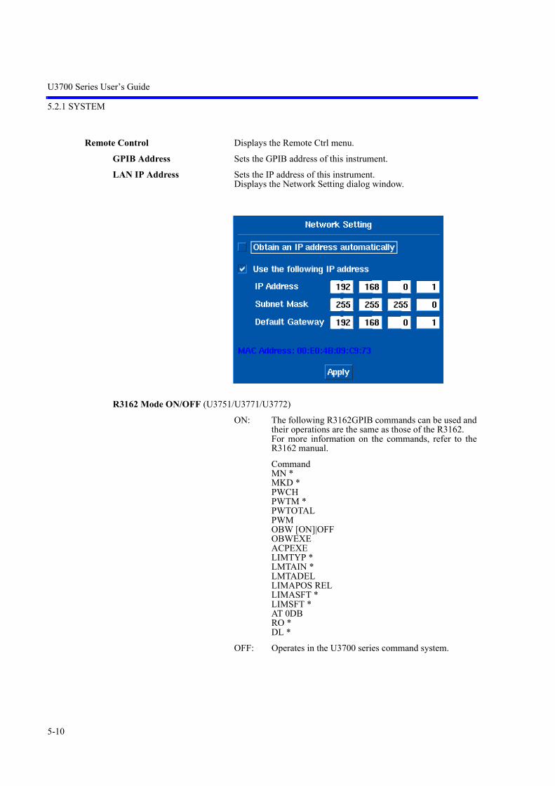
U3700 Series User’s Guide
5.2.1 SYSTEM
5-10
Remote Control Displays the Remote Ctrl menu.
GPIB Address Sets the GPIB address of this instrument.
LAN IP Address Sets the IP address of this instrument.Displays the Network Setting dialog window.
R3162 Mode ON/OFF (U3751/U3771/U3772)
ON: The following R3162GPIB commands can be used andtheir operations are the same as those of the R3162.For more information on the commands, refer to theR3162 manual.
CommandMN *MKD *PWCHPWTM *PWTOTALPWMOBW [ON]|OFFOBWEXEACPEXELIMTYP *LMTAIN *LMTADELLIMAPOS RELLIMASFT *LIMSFT *AT 0DBRO *DL *
OFF: Operates in the U3700 series command system.

U3700 Series User’s Guide
5.2.1 SYSTEM
5-11
R3131 Mode ON/OFF (U3741)
ON: Except for certain R3131/R3131A functions, the sameGPIB commands as those for the R3131/R3131A canbe used. For more information on commands, refer tothe R3131 Series Operation Manual.
Unavailable functions: Trigger (LINE), EMC, Calibration, Hard Copy
OFF: Operates in the U3700 series command system.
Parser AT/SCPI Selects a remote command set to be used.
AT: The AT (Advantest) command set is selected.
SCPI: The SCPI command set is selected.
Trace Points 501/1001 Switches the horizontal axis trace points to 501 or 1001.
501: Sets trace points to 501 points.
1001: Sets trace points to 1001 points.
Calibration Displays the Calibration menu.
Calibrate ALL Performs all calibrations.
Each Item Displays the Each Item menu.
Total Gain RF Path 1 Measures the absolute error at 20 MHz based on the CAL signalthat is input to the RF INPUT 1 connector.
Total Gain RF Path 2 Measures the absolute error at 20 MHz based on the CAL signalthat is input to the RF INPUT 2 connector. (U3771, U3772)
Step ATT CAL Measures the error at 20 MHz when switching ATT.
RBW CAL Automatically adjusts IF filters.
PBW Performs the calibration of the noise power bandwidth.
Report HIDE/SHOW Hides or displays the calibration results.
Calibration F Int Ref Calibrates the frequency of the crystal oscillator that is used forthe internal frequency reference.
Coarse Changes the data of the coarse adjustment.
Fine Changes the data of the fine adjustment.
Store Saves the adjusted data.The saved data is used even if this instrument is preset.
Default Sets the calibration data when this instrument is shipped from thefactory.
Calibration Corrections ON/OFFSwitches the calibration factor ON and OFF.
ON: Uses the CAL factor.
OFF: Does not use the CAL factor.
Frequency Correction ON/OFFSwitches the frequency correction function ON and OFF.
ON: Corrects the frequency characteristics.
OFF: Cancels the frequency correction function.

U3700 Series User’s Guide
5.2.1 SYSTEM
5-12
More 1/2 Displays the System 2/2 menu.
Color Pattern
Color1 Selects the standard color.
Color2 Selects the second set of colors.
Black and White Selects the black and white mode (white traces).
White and Black Selects the white and black mode (black traces).
User Password Sets the password used to lock the panel.The password is set to [0,0,0,0] when this instrument is shippedfrom the factory.The password can be changed in the dialog box.
A password can be initialized (0,0,0,0) through the GPIB.GPIB AT command: "RPWD"
Date Time Displays the Date Time menu.
Edit Date Time Sets a date and time.They are set or changed in the dialog window.
Year: Set a year.
Month: Set a month.
Day: Set a date.
Hour: Set an hour.
Minute: Set a minute.

U3700 Series User’s Guide
5.2.1 SYSTEM
5-13
Format Sets date display formats.They are set or changed in the dialog window.
Show ON/OFF Switches ON and OFF the date display.
ON: Displays the date.
OFF: Hides the date display.
Copy Config Displays the Copy menu.
Copy Outputs screen data according to Config.
Copy Device FILE/PRT Specifies the copy output device.
FILE: Selects an external USB memory device.
PRT: Selects a printer.
Screen Shot Config Displays the File Config menu.
File Format PNG/BMPSelects either PNG (portable network graphics) or BMP (bit map)as the file format.
Auto Inc ON/OFF Sets the automatic incremental function of the file number.
ON: Increments the file number when the screen data iscopied.
OFF: The file COPYxxx.BMP(PNG) is overwritten.
Auto Inc Index Sets the start number to increment automatically.

U3700 Series User’s Guide
5.2.1 SYSTEM
5-14
Menu ON/OFF Hides the soft menu area when a copy is output.
ON: Displays the menu.
OFF: Hides the menu.
File Control Displays the Shot File menu.Displays the Files window.
Rename File Changes the selected filename.
Remove File Deletes the selected file.
Write Protect ON/OFFWrite-protects the selected file.
ON: Prevents data from being written to the file.
OFF: Allows data to be written to the file.

U3700 Series User’s Guide
5.2.1 SYSTEM
5-15
Media Selects the media on which to save data.Selects the external USB memory device in the dialog box.
NOTE: Data cannot be saved in the internal memory.
Print Config
Paper Format Selects the paper size and print direction.
Color Mode Color/GraySelects either color or gray scale in the Print Config mode.
Menu ON/OFF Displays or hides the soft menu when a file is printed.
ON: Displays the menu
OFF: Hides the menu.
Config Driver Selects a printer driver to be used.The Printer Driver Management window is displayed.
Driver files:Printer drivers registered in this instrument are listed.Select a driver name to be used by using the knob.
Your choice:The selected driver name is displayed.
Test driver:Starts a test printing using the selected driver.
Default: This instrument automatically selects a driver.
U3700 Series User’s Guide
5.2.1 SYSTEM
5-16
Use it: Decides to use the selected driver.
Self Test Displays the Self Test menu.
Execute Self Test Executes the self-test.The self-test is the same as when the power turns on.
Test Items1. Supply_Voltage2. Memory3. CPU_Registers4. RF_Registers5. RF_PLL_LOCK6. LO_Registers7. LO_PLL_LOCK8. AIF_Registers9. AIF_PLL_LOCK10. TG_Registers11. Temperature
Factory Init Initializes this instrument to the factory settings.Refer to “A.1 Initial Setting List.”

U3700 Series User’s Guide
5.2.2 APPLI
5-17
5.2.2 APPLI
Displays the APPLI menu.
Spectrum Analyzer
2 Channels Viewer Displays the 2 Channel menu. Functions only for the U3771 or U3772.
2 Channel ON/OFF Sets the 2 Channels Viewer mode. The sweep and measurement are performed only for the activechannel. The active channel screen is enclosed within a red frame.
ON: Splits the screen into an upper and lower windows.Upper window: RF INPUT 2Lower window: RF INPUT 1
OFF: Cancels the dual-screen display.The measurement display returns to the active channelscreen.
Spectrum RF1 Cancels the 2 Channel mode and enables RF INPUT 1.
Spectrum RF2 Cancels the 2 Channel mode and enables RF INPUT 2.
2 Channel Preset Initializes the RF INPUT 1 and RF INPUT 2 settings.
APPLI
Spectrum Analyzer
2 Channels Viewer 2 Channel ON/OFF
Spectrum RF1
Spectrum RF2
2 Channel Preset
Context RF2|RF1

U3700 Series User’s Guide
5.2.3 FILE
5-18
Context RF2|RF1 Switches the active screen.
RF2: The RF2 (upper window) settings can be changed.
RF1: The RF1 (lower window) settings can be changed.
5.2.3 FILE
Displays the File menu.
Save Saves the items specified in Items to the memory device specifiedin Media.The format in which to save data can be selected from eitherbinary (.dat) or XML (eXtensible Markup Language) (.xml).
File size (For saving the setting data)
BIN: Approximately 4.8 KB
XML: Approximately 16 KB
NOTE: Only binary data can be saved in the internal memory.
FILE
Save
Save as
File Control
Recall
Items
Title
Media
Auto-name Radix
Auto name Index
File Format BIN/XML
Format Media
Rename File
Remove File
Write Protect ON/OFF
Copy All to Flash
Copy All to USB
More 1/2

U3700 Series User’s Guide
5.2.3 FILE
5-19
Save as Specifies the filename and saves the file.Displays the Save As window.
File Control Displays the File Control menu and Files window.
Rename File Changes the selected filename.
Remove File Deletes the selected file.
Write Protect ON/OFF Write-protects the selected file.
ON: Prevents data from being written to the file.
OFF: Allows data to be written to the file.
U3700 Series User’s Guide
5.2.3 FILE
5-20
Copy All to Flash Copies all files in the USB memory key to the internal memory.(*)
Copy All to USB Copies all files in the internal memory to the USB memory key.(*)
* :
• The file format that can be copied into the USB memory key is".dat". The screen image cannot be copied.<-->\adv\dat.
• If the same file name exists in the USB memory key, the file isoverwritten.
• Select USB memory from the Media menu.
More 1/2 Displays the File Ctrl menu (2/2).
Auto-name Radix Defines the common part of the filename under which files aresaved.The file name follows the following format "Radix+Index".When a file is saved, an extension [.dat] is automatically added tothe file name which is saved in the format "Radix+Index.dat".Radix can be up to six characters long.
Auto name Index Specifies the Index part of the filename, under which files aresaved.The Index increments by 1 each time a file is saved.Zero to 99 can be specified in the Index.
File Format BIN/XML
BIN: Saves the data in binary format.Only binary formats can be saved in the internalmemory.The settings of files saved in binary format canbe recalled.
XML: Saves the data in XML format.Files which are saved in XML format can be read easilybut the settings cannot be recalled.
Format Media Formats external USB memory devices.Do not remove the memory device while the memory is being for-matted.

U3700 Series User’s Guide
5.2.3 FILE
5-21
Recall Recalls file which was saved in binary format and displays the set-tings and trace data.Displays the Recall window. Execute Recall in the same mode as when the file was saved. Mode is displayed in File Info of the Recall window. The fontcolor is green for a Recall-enabled file and red for a Recall-dis-abled file.
Items Selects items to be saved.Displays the Items dialog box.
Setup: Saves the setting conditions.
Traces Context A A/B/C:Saves the trace data. Even if the Write mode is set, the setting is changed tothe View mode while the trace data is recalled.
Green: Recall can be executed.
Red: Recall cannot be executed.

U3700 Series User’s Guide
5.2.3 FILE
5-22
Traces Context B A/B
Limit Lines:Saves the Limit Line table.
Channel: Saves the Channel Formula table and Channel Table.
ACP: Saves CS/BS Table for the ACP.
SEM: Saves SEM Table.
Spurious 1/2/3:Saves the Spurious Bands table.
Corr Factor:Saves Correction Factor Table.
Normalize Context A/B/C:Saves Normz Data that uses the TG.
Title Displays the Edit Title dialog box.
How to enter
Pressing a key cycles through a list of characters, which are allocated to that key,and displays them at the cursor position. If the key is not pressed for a few sec-onds after the previous key entry or another key is pressed, the displayed charac-ter is entered.
Table 5-1 Character allocation table
Key Allocated Characters
0 0
. . space , ; :- + _ = # < > ! ?
- [Back Space]
1 1
2 a b c 2
3 d e f 3
4 g h i 4
5 j k l 5
6 m n o 6
7 p q r s 7
8 t u v 8
9 w x y z 9

U3700 Series User’s Guide
5.2.3 FILE
5-23
To enter a capital letter, hold down the SHIFT key and a key.
1. Enter a character by using the keypad.
2. Press a unit key such as the Hz key to finish entering the title.
3. Press Title to close the Edit Title dialog box.
Media Displays the Media dialog box.Selects either the internal memory or an external USB memorydevice in the dialog box.
U3700 Series User’s Guide
5.2.4 COPY
5-24
5.2.4 COPY
Outputs a screen image according to the conditions set by pressing SYSTEM, MORE 1/2, and COPYConfig.
The COPY menu can also be displayed by pressing the SHIFT key and COPY key.
File size (For saving the image data)
PNG: Approximately 8 KB
BMP: Approximately 150 KB
5.2.5 HELP
Pressing the HELP key displays "HELP?" which indicates the HELP mode.
NOTE: The HELP file is loaded the first time the HELP key is pressed after the power is turned on.
When the HELP mode is set
Press a soft menu key to display the relevant menu description.
Press the soft menu key again to hide the display.
Press the HELP key again to cancel the HELP mode.
Procedure
1. Select a menu.
2. Press the Help key.
3. Press a soft menu key.
4. Press the HELP key to cancel the HELP mode.
5. Repeat from step 1 to display the HELP of other menus.

U3700 Series User’s Guide
5.2.6 MEAS 1
5-25
5.2.6 MEAS 1
Displays the Meas 1 menu.
MEAS 1
Channel Power
Total Power
Average Power
OBW
ACP
Spectrum Emission
Spurious
Channel Power Execute ON/OFF
Average Control
On Trace A/B/C
Channel Position
Channel Width
Default Conditions
Averaging ON/OFF
Max Sweep Count
Average ONCE/SLIDE
(a)(b)(c)(d)
(e)(f)(g)
(a)
Restore Defaults
Save Defaults
Total Power Execute ON/OFF
Average Control
On Trace A/B/C
Default Conditions
Averaging ON/OFF
Max Sweep Count
Average ONCE/SLIDE
(b)
Restore Defaults
Save Defaults
Average Power Execute ON/OFF
Average Control
On Trace A/B/C
Window
Default Conditions
Averaging ON/OFF
Max Sweep Count
Average ONCE/SLIDE
(c)
Range FULL/WIN
Window Position
Window Width
Restore Defaults
Save Defaults
Restore Defaults
Save Defaults
OBW Execute ON/OFF
Average Control
On Trace A/B/C
%OBW
Default Conditions
Averaging ON/OFF
Max Sweep Count
Average ONCE/SLIDE
(d)
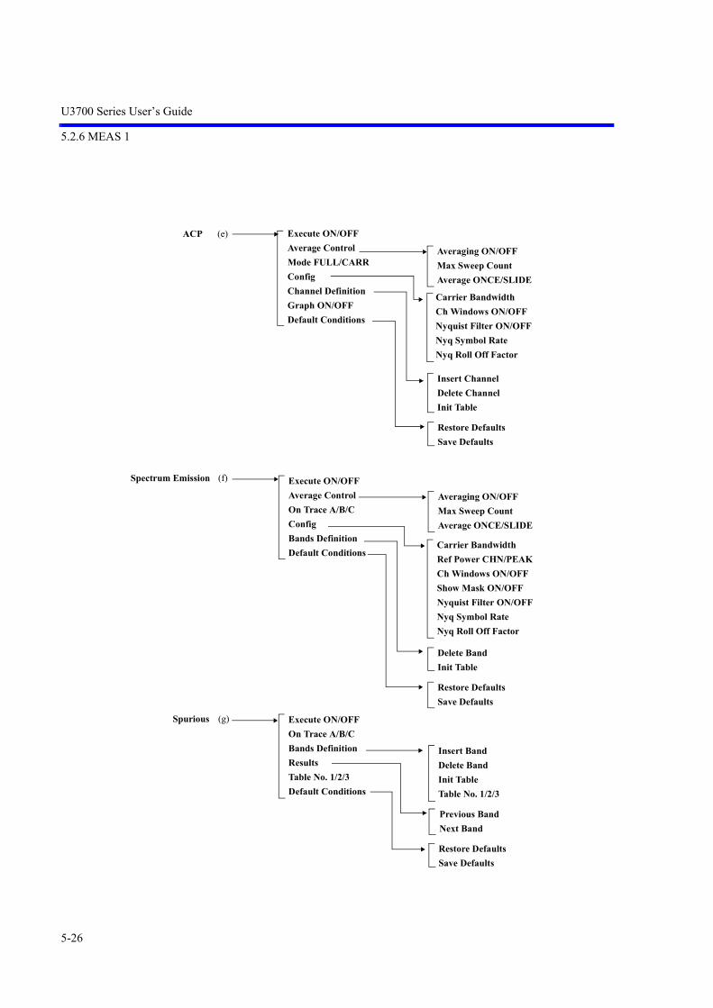
U3700 Series User’s Guide
5.2.6 MEAS 1
5-26
Spectrum Emission Execute ON/OFF
Average Control
On Trace A/B/C
Config
Bands Definition
Default Conditions
Averaging ON/OFF
Max Sweep Count
Average ONCE/SLIDE
(f)
Spurious Execute ON/OFF
On Trace A/B/C
Bands Definition
Results
Table No. 1/2/3
Default Conditions
Insert Band
Delete Band
Init Table
Table No. 1/2/3
(g)
Restore Defaults
Save Defaults
ACP Execute ON/OFF
Average Control
Mode FULL/CARR
Config
Channel Definition
Graph ON/OFF
Default Conditions
Averaging ON/OFF
Max Sweep Count
Average ONCE/SLIDE
(e)
Insert Channel
Delete Channel
Init Table
Carrier Bandwidth
Ch Windows ON/OFF
Nyquist Filter ON/OFF
Nyq Symbol Rate
Nyq Roll Off Factor
Carrier Bandwidth
Ref Power CHN/PEAK
Ch Windows ON/OFF
Show Mask ON/OFF
Nyquist Filter ON/OFF
Nyq Symbol Rate
Nyq Roll Off Factor
Delete Band
Init Table
Restore Defaults
Save Defaults
Previous Band
Next Band
Restore Defaults
Save Defaults
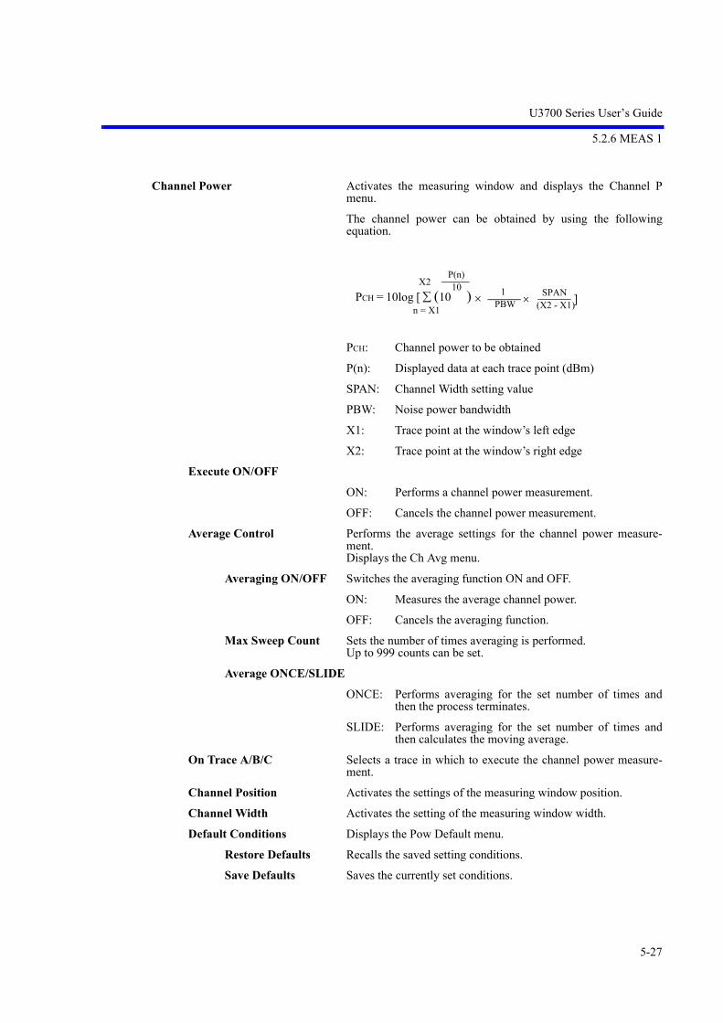
U3700 Series User’s Guide
5.2.6 MEAS 1
5-27
Channel Power Activates the measuring window and displays the Channel Pmenu.
The channel power can be obtained by using the followingequation.
PCH: Channel power to be obtained
P(n): Displayed data at each trace point (dBm)
SPAN: Channel Width setting value
PBW: Noise power bandwidth
X1: Trace point at the window’s left edge
X2: Trace point at the window’s right edge
Execute ON/OFF
ON: Performs a channel power measurement.
OFF: Cancels the channel power measurement.
Average Control Performs the average settings for the channel power measure-ment.Displays the Ch Avg menu.
Averaging ON/OFF Switches the averaging function ON and OFF.
ON: Measures the average channel power.
OFF: Cancels the averaging function.
Max Sweep Count Sets the number of times averaging is performed.Up to 999 counts can be set.
Average ONCE/SLIDE
ONCE: Performs averaging for the set number of times andthen the process terminates.
SLIDE: Performs averaging for the set number of times andthen calculates the moving average.
On Trace A/B/C Selects a trace in which to execute the channel power measure-ment.
Channel Position Activates the settings of the measuring window position.
Channel Width Activates the setting of the measuring window width.
Default Conditions Displays the Pow Default menu.
Restore Defaults Recalls the saved setting conditions.
Save Defaults Saves the currently set conditions.
X2 10
n = X1
P(n)
(X2 - X1)1
PBW SPAN ]PCH = 10log [ (10 )
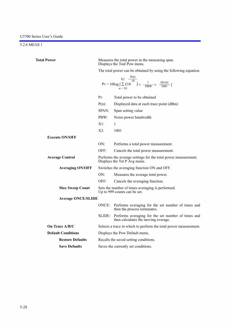
U3700 Series User’s Guide
5.2.6 MEAS 1
5-28
Total Power Measures the total power in the measuring span.Displays the Toal Pow menu.
The total power can be obtained by using the following equation.
PT: Total power to be obtained
P(n): Displayed data at each trace point (dBm)
SPAN: Span setting value
PBW: Noise power bandwidth
X1: 1
X2: 1001
Execute ON/OFF
ON: Performs a total power measurement.
OFF: Cancels the total power measurement.
Average Control Performs the average settings for the total power measurement.Displays the Tot P Avg menu.
Averaging ON/OFF Switches the averaging function ON and OFF.
ON: Measures the average total power.
OFF: Cancels the averaging function.
Max Sweep Count Sets the number of times averaging is performed.Up to 999 counts can be set.
Average ONCE/SLIDE
ONCE: Performs averaging for the set number of times andthen the process terminates.
SLIDE: Performs averaging for the set number of times andthen calculates the moving average.
On Trace A/B/C Selects a trace in which to perform the total power measurement.
Default Conditions Displays the Pow Default menu.
Restore Defaults Recalls the saved setting conditions.
Save Defaults Saves the currently set conditions.
X2 10
n = X1
P(n)
10011
PBW SPAN ]PT = 10log [ (10 )

U3700 Series User’s Guide
5.2.6 MEAS 1
5-29
Average Power Measures the average power in the measuring range.Displays the Average P menu.
The average power can be obtained by using the followingequation.
PAVG: Average power to be obtained
P(n): Displayed data at each trace point (dBm)
X1: 1
X2: 1001
Execute ON/OFF
ON: Performs an average power measurement.
OFF: Cancels the average power measurement.
Average Control Performs the average settings for the average power measure-ment.
Displays the Av P Avg menu.
Averaging ON/OFF Switches the averaging function ON and OFF.
ON: Measures the average power.
OFF: Cancels the averaging function.
Max Sweep Count Sets the number of times averaging is performed.Up to 999 counts can be set.
Average ONCE/SLIDE
ONCE: Performs averaging for the set number of times andthen the process terminates.
SLIDE: Performs averaging for the set number of times andthen calculates the moving average.
On Trace A/B/C Selects a trace in which to execute the average power measure-ment.
Window Sets a measuring range in which to execute the average powermeasurement.Displays the Avg P Win menu.
Range FULL/WIN
FULL: Measures the average power in the full measuring span.
WIN: Measures the average power in the measuring window.
Window Position Sets the measuring window position.
Window Width Sets the measuring window width.
Default Conditions Displays the Pow Default menu.
Restore Defaults Recalls the saved setting conditions.
Save Defaults Saves the currently set conditions.
X2 10
n = X1
P(n)
10011 ]PAVG = 10log [ (10 )

U3700 Series User’s Guide
5.2.6 MEAS 1
5-30
OBW Displays the OBW menu.
Execute ON/OFF
ON: Performs an occupied bandwidth measurement.
OFF: Cancels the occupied bandwidth measurement.
Average Control
Averaging ON/OFF Switches the averaging function ON and OFF.
ON: Measures the occupied bandwidth power.
OFF: Cancels the averaging function.
Max Sweep Count Sets the number of times averaging is performed.Up to 999 counts can be set.
Average ONCE/SLIDE
ONCE: Performs averaging for the set number of times andthen the process terminates.
SLIDE: Performs averaging for the set number of times andthen calculates the moving average.
On Trace A/B/C Selects a trace in which to execute the occupied bandwidth mea-surement.
%OBW Sets the ratio of the occupied bandwidth power to the total powerin percentage.The initial value is 99%.
Default Conditions Displays the OBW Default menu.
Restore Defaults Recalls the saved setting conditions.
Save Defaults Saves the currently set conditions.
ACP Displays the ACP menu.
Execute ON/OFF
ON: Performs the adjacent channel leakage powermeasurement.
OFF: Cancels the adjacent channel leakage powermeasurement.
Average Control
Averaging ON/OFF Switches the averaging function ON and OFF.
ON: Measures the adjacent channel leakage power.
OFF: Cancels the averaging function.
Max Sweep Count Sets the number of times averaging is performed.Up to 999 counts can be set.
Average ONCE/SLIDE
ONCE: Performs averaging for the set number of times andthen the process terminates.
MUL: Performs averaging for the set number of times andthen calculates the moving average.
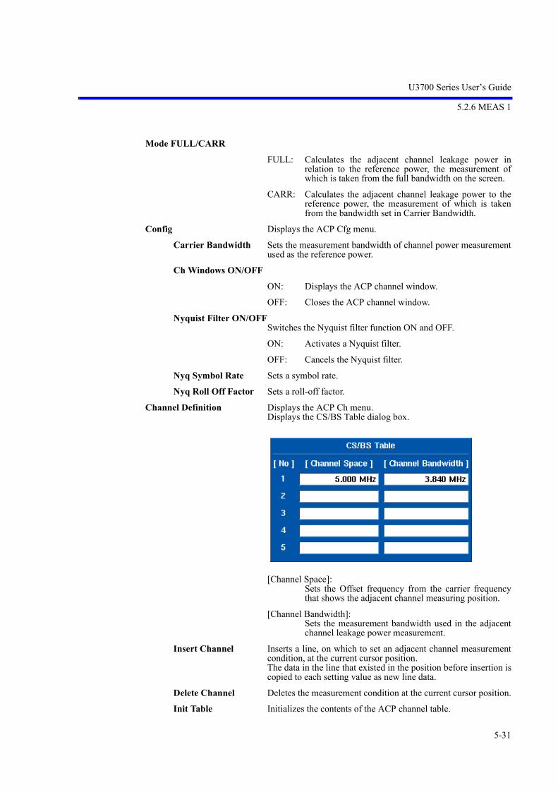
U3700 Series User’s Guide
5.2.6 MEAS 1
5-31
Mode FULL/CARR
FULL: Calculates the adjacent channel leakage power inrelation to the reference power, the measurement ofwhich is taken from the full bandwidth on the screen.
CARR: Calculates the adjacent channel leakage power to thereference power, the measurement of which is takenfrom the bandwidth set in Carrier Bandwidth.
Config Displays the ACP Cfg menu.
Carrier Bandwidth Sets the measurement bandwidth of channel power measurementused as the reference power.
Ch Windows ON/OFF
ON: Displays the ACP channel window.
OFF: Closes the ACP channel window.
Nyquist Filter ON/OFFSwitches the Nyquist filter function ON and OFF.
ON: Activates a Nyquist filter.
OFF: Cancels the Nyquist filter.
Nyq Symbol Rate Sets a symbol rate.
Nyq Roll Off Factor Sets a roll-off factor.
Channel Definition Displays the ACP Ch menu.Displays the CS/BS Table dialog box.
[Channel Space]: Sets the Offset frequency from the carrier frequencythat shows the adjacent channel measuring position.
[Channel Bandwidth]: Sets the measurement bandwidth used in the adjacentchannel leakage power measurement.
Insert Channel Inserts a line, on which to set an adjacent channel measurementcondition, at the current cursor position.The data in the line that existed in the position before insertion iscopied to each setting value as new line data.
Delete Channel Deletes the measurement condition at the current cursor position.
Init Table Initializes the contents of the ACP channel table.

U3700 Series User’s Guide
5.2.6 MEAS 1
5-32
Graph ON/OFF
ON: Displays an ACP graph.
OFF: Hides the ACP graph.
Default Conditions Displays the ACP Default menu.
Restore Defaults Recalls the saved setting conditions.
Save Defaults Saves the currently set conditions.
Spectrum Emission Displays the SEM (Spectrum Emission Mask) menu.
Execute ON/OFF
ON: Performs a spectrum emission mask measurement.
OFF: Terminates the spectrum emission mask measurement.
Average Control Displays the SEM Avg menu.
Averaging ON/OFF Switches the averaging function ON and OFF.
ON: Measures the spectrum emission mask.
OFF: Cancels the averaging function.
Max Sweep Count Sets the number of times averaging is performed.Up to 999 counts can be set.
Average ONCE/SLIDE
ONCE: Performs averaging for the set number of times andthen the process terminates.
SLIDE: Performs averaging for the set number of times andthen calculates the moving average.
On Trace A/B/C Selects a trace in which to execute the spectrum emission maskmeasurement.
Config Displays the SEM Cfg menu.
Carrier Bandwidth Sets the power conversion bandwidth for carrier signals.
Ref Power CHN/PEAKSwitches the calculation mode of the reference power between theChannel mode and the Peak Power mode.
CHN: Calculates the channel power and sets the result as thereference power for the mask measurement.
PEAK: Sets the Peak power value of the waveform as thereference power for the mask measurement.
Ch Windows ON/OFF
ON: Displays the SEM window.
OFF: Hides the SEM window.
Show Mask ON/OFF
ON: Displays the Mask line.
OFF: Hides the Mask line.
Nyquist Filter ON/OFFSwitches the Nyquist filter function ON and OFF.

U3700 Series User’s Guide
5.2.6 MEAS 1
5-33
ON: Activates the Nyquist filter.
OFF: Cancels the Nyquist filter.
Nyq Symbol Rate Sets a symbol rate.
Nyq Roll Off Factor Sets a roll-off factor.
Bands Definition Displays the SEM Bands menu and SEM Table window.
Delete Band Deletes a column of measurement conditions from the currentcursor position.
Init Table Initializes all data in the table.
[Start] Sets the offset frequency from the center frequency as the startfrequency of the emission mask judgment frequency band.
[Stop] Sets the offset frequency from the center frequency as the stop fre-quency of the emission mask judgment frequency band.
[Integral BW] Sets the power integral bandwidth at each frequency point.
[Judge] Specifies how to compare the waveform with the set mask values(absolute or relative values) when the mask judgment is per-formed.
Absolute:Compares the waveform with the mask values set inLimit Abs Start and Limit Abs Stop. If the waveform isequal to or less than the mask values, the result is Pass.
Relative: Compares the waveform with the mask values set inLimit Rel Start and Limit Rel Stop. If the waveform isequal to or less than the mask values, the result is Pass.
Abs and Rel:Compares the waveform with both the Limit Abs Start,Limit Abs Stop values and the Limit Rel Start, LimitRel Stop values. If both conditions are satisfied, Pass isdisplayed.
Abs or Rel:Compares the waveform with both the Limit Abs Start,Limit Abs Stop values and the Limit Rel Start, LimitRel Stop values. If either of the conditions is satisfied,Pass is displayed.

U3700 Series User’s Guide
5.2.6 MEAS 1
5-34
[Limit Abs Start] Sets the absolute mask value at the position of the start frequency.
[Limit Abs Stop] Sets the absolute mask value at the position of the stop frequency.A mask value at a position between the start and stop frequenciesis calculated by using the linear interpolation.
[Limit Rel Start] Sets the relative mask value at the position of the start frequency.The set mask value is used to compare with the offset value fromthe measured reference power.
[Limit Rel Stop] Sets the relative mask value at the position of the stop frequency.A mask value at a position between the start and stop frequenciesis calculated by using the linear interpolation.
Default Conditions Displays the SEM Default menu.
Restore Defaults Recalls the saved setting conditions.
Save Defaults Saves the currently set conditions.
Spurious Displays the Spurious menu.
Execute ON/OFF
ON: Performs the spurious measurement.
OFF: Terminates the spurious measurement.
On Trace A/B/C Selects a trace in which to execute the spurious measurement.
Bands Definition Displays the Spr Config menu.At the same time, the Spurious Bands setting window is dis-played. The start and stop frequencies of the spurious measurement band,the RBW, VBW, sweep time, attenuator, reference level, preampON or OFF, and the judgment level value used in the measure-ment can be set in the Spurious Bands setting window.

U3700 Series User’s Guide
5.2.6 MEAS 1
5-35
Insert Band Inserts a column, in which spurious measurement conditions canbe set, at the current cursor position.The data contained in the row that existed in the position beforeinsertion is copied to each setting value as new row data.
Delete Band Deletes a column of measurement conditions from the currentcursor position.
Init Table Initializes all data in the table currently being edited.
Table No. 1/2/3 Sets the setting sequence table number for the spurious measure-ment to 1, 2, or 3.
1: Sets table number 1.
2: Sets table number 2.
3: Sets table number 3.
Results Displays the Spr Results menu.Displays Spurious Measure Results Table.
Previous Band Displays the previous screen.
Next Band Displays the next screen.
Table No. 1/2/3 Sets the setting sequence table number for the spurious measure-ment to 1, 2, or 3.
1: Sets table number 1.
2: Sets table number 2.
3: Sets table number 3.
Default Conditions Displays the Spr Default menu.
Restore Defaults Recalls the saved setting conditions.
Save Defaults Saves the currently set conditions.
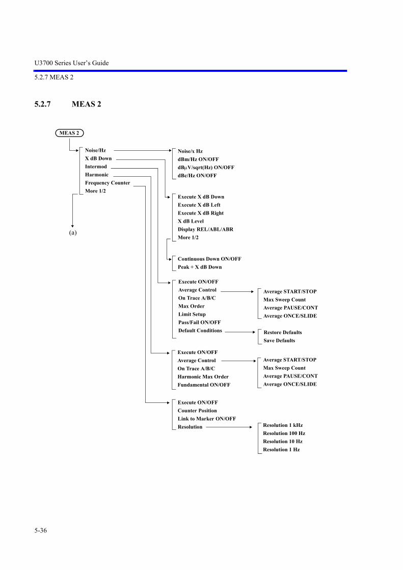
U3700 Series User’s Guide
5.2.7 MEAS 2
5-36
5.2.7 MEAS 2
MEAS 2
Noise/Hz
X dB Down
Intermod
Harmonic
Frequency Counter
More 1/2
Noise/x Hz
dBm/Hz ON/OFF
dBV/sqrt(Hz) ON/OFF
dBc/Hz ON/OFF
Continuous Down ON/OFF
Peak + X dB Down
Execute X dB Down
Execute X dB Left
Execute X dB Right
X dB Level
Display REL/ABL/ABR
More 1/2
Average START/STOP
Max Sweep Count
Average PAUSE/CONT
Average ONCE/SLIDE
Restore Defaults
Save Defaults
Average START/STOP
Max Sweep Count
Average PAUSE/CONT
Average ONCE/SLIDE
Resolution 1 kHz
Resolution 100 Hz
Resolution 10 Hz
Resolution 1 Hz
Execute ON/OFF
Counter Position
Link to Marker ON/OFF
Resolution
Execute ON/OFF
Average Control
On Trace A/B/C
Max Order
Limit Setup
Pass/Fail ON/OFF
Default Conditions
Execute ON/OFF
Average Control
On Trace A/B/C
Harmonic Max Order
Fundamental ON/OFF
(a)

U3700 Series User’s Guide
5.2.7 MEAS 2
5-37
Noise/Hz Displays the Noise/Hz menu.
Noise/x Hz Activates settings of the noise measurement bandwidth.The initial value is 1 Hz.
dBm/Hz ON/OFF
ON: Displays the marker automatically if the marker is set toOFF.Sets the vertical axis unit to dBm and sets the markerunit to dBm/Hz.
OFF: Terminates the dBm/Hz function.
dBV/sqrt(Hz) ON/OFF
ON: Displays the marker automatically if the marker is set toOFF.Sets the vertical axis unit to dBV and sets the markerunit to dBV/sqrt(Hz).
OFF: Terminates the dBV/sqrt(Hz) function.
dBc/Hz ON/OFF
ON: Automatically sets the marker to the delta marker modeif the marker is set to OFF.Sets the delta marker unit to dBc/Hz.
OFF: Terminates the dBc/Hz function.
X dB Down Displays the X dB Down menu.Displays the marker automatically if the marker is set to OFF.The trace, for which the X dB Down function is executed, is theactive trace.Set the marker on the active trace.
Execute X dB Down According to the Mode setting, displays a normal marker and adelta marker X dB lower than the current position.
Execute X dB Left Displays a normal marker to the left of and X dB lower than thecurrent position.
Execute X dB Right Displays a normal marker to the right of and X dB lower than thecurrent position.
X dB Level Activates the X dB Level setting.
Execute ON/OFF
Mod. Freq to Sweep Time ON/OFF
Peak Delta Y
%AM Meas ON/OFF
FM Meas
Sound
(a)
Execute ON/OFF
Sound AM/FM
Volume
Pause Time

U3700 Series User’s Guide
5.2.7 MEAS 2
5-38
Display REL/ABL/ABR Sets the display method of the X dB Down marker data.
REL: Sets the marker to the delta marker mode when X dBDown is executed.Displays a normal marker on the right and a deltamarker on the left.
ABL: Displays the left marker as an absolute value.
ABR: Displays the right marker as an absolute value.
More 1/2 Displays the XdB 2/2 menu.
Continuous Down ON/OFF Switches the continuous X dB down function ON and OFF.
ON: Repeats Peak X dB down in every sweep.
OFF: Cancels the continuous X dB down function.
Peak + X dB Down Performs the peak search in the search range and then executes XdB Down.
Intermod Displays the Intermod menu.
Execute ON/OFF
ON: Performs the intermodulation measurement.
OFF: Terminates the intermodulation measurement.
Average Control
Average START/STOP
START: Performs averaging.
STOP: Cancels averaging.
Max Sweep Count Sets the number of times Video averaging is performed.Up to 999 counts can be set.
Average PAUSE/CONT
PAUSE: Pauses averaging and displays the current number oftimes averaging has been performed.
CONT: Restarts averaging from the point at which averagingwas paused.
Average ONCE/SLIDE
ONCE: Performs averaging for the set number of times andthen the process terminates.
SLIDE: Performs averaging for the set number of times andrepeats averaging continuously by using the last data.
On Trace A/B/C Selects a trace in which to execute the inter-modulation measure-ment.
Max Order Sets the measuring order. The third, fifth, seventh, and ninthorders can be set.

U3700 Series User’s Guide
5.2.7 MEAS 2
5-39
Limit Setup Displays the Limit Setup dialog box.
[3rd Order Limit]:Sets the limit value of the third-order distortion signal.
[5th Order Limit]:Sets the limit value of the fifth-order distortion signal.
[7th Order Limit]:Sets the limit value of the seventh-order distortionsignal.
[9th Order Limit]:Sets the limit value of the ninth-order distortion signal.
Pass/Fail ON/OFF Switches the Pass/Fail judgment due to the comparison with thelimit value set in the Limit Setup dialog box ON and OFF.
ON: Performs the Pass/Fail judgment.If the measurement result is larger than the set limitvalue, a Fail judgment is performed.
OFF: Does not perform the Pass/Fail judgment.
Default Conditions Displays the IM Default menu.
Restore Defaults Recalls the saved setting conditions.
Save Defaults Saves the currently set conditions.
Harmonic Displays the Harmonic menu.
Execute ON/OFF
ON: Executes the harmonic measurement function.
OFF: Terminates the harmonic measurement function.
Average Control
Average START/STOP
START: Performs averaging.
STOP: Cancels averaging.
Max Sweep Count Sets the number of times Video averaging is performed.Up to 999 counts can be set.
U3700 Series User’s Guide
5.2.7 MEAS 2
5-40
Average PAUSE/CONT
PAUSE: Pauses averaging and displays the current number oftimes averaging has been performed.
CONT: Restarts averaging from the point at which averagingwas paused.
Average ONCE/SLIDE
ONCE: Performs averaging for the set number of times andthen the process terminates.
SLIDE: Performs averaging for the set number of times andrepeats averaging continuously by using the last data.
On Trace A/B/C Selects a trace in which to execute the harmonic measurement.
Harmonic Max Order Sets the measuring harmonic order.The measuring order can be set from 1 to 10.The default value is 3.
Fundamental ON/OFF
ON: Sets the fundamental frequency.The measuring span is set in the range that includes thefundamental and set harmonic order frequencies.
OFF: Sets the current center frequency to the fundamentalfrequency.
Frequency Counter Displays the Counter menu.
Execute ON/OFF
ON: Sets a frequency counter mode.
OFF: Cancels the frequency counter mode.
Counter Position Adjusts a cursor on the measured signal.
Link to Marker ON/OFF Corresponds the cursor at the counter position with the markerposition. If the marker position moved, then the counter position alsomoved.
OFF: Cancels the function.
Resolution Displays the Cnt Res menu.
Resolution 1 kHz Sets the resolution of the frequency counter to 1 kHz.
Resolution 100 Hz Sets the resolution of the frequency counter to 100 Hz.
Resolution 10 Hz Sets the resolution of the frequency counter to 10 Hz
Resolution 1 Hz Sets the resolution of the frequency counter to 1 Hz.
More 1/2 Displays the Meas2 2/2 menu.
%AM Meas ON/OFF Switches ON and OFF the %AM modulation factor measurement.
ON: Acquires an AM modulation factor and modulationfrequency by using the peak search function anddisplays a calculation result in percentage.
OFF: Cancels the %AM function.
U3700 Series User’s Guide
5.2.7 MEAS 2
5-41
FM Meas Displays the FM Meas menu.
Execute ON/OFF Switches ON and OFF the frequency deviation measurementfunction.
ON: Measures the frequency deviation of an FM signal.
OFF: Cancels the frequency deviation measurement functionof an FM signal.
A value of Peak Delta Y is used as a condition of performing thepeak search.
If setting the Mod. Freq to Sweep Time ON/OFF menu to ON andsetting a modulation frequency in advance, a optimum sweep timeis automatically set based on the modulation frequency and thenumber of display points.
If OFF is set for the Mod. Freq to Sweep Time ON/OFF menu, asufficient sweep time must be set according to the following for-mula:
SWP > PT 1 / Fmod
SWP: Sweep time
PT: The number of display trace points
Fmod: Modulation frequency
(When the FM Meas function is selected, the trace detector isautomatically set to the Posi mode.)
Mod. Freq to Sweep Time ON/OFFSwitches ON and OFF a mode, in which a sweep time is deter-mined based on a modulation frequency.
ON: Sets a modulation frequency and then sets a sweep timebased on the modulation frequency.
OFF: Cancels a mode in which a modulation frequency is set.
A value set for SWP Time AUTO/MNL is applied to a sweep timewhen measurement starts.
Peak Delta Y Sets a level difference for a signal to be judged as a peak pointduring the peak search. A level difference set here is used as athreshold level while searching for a peak value.
Sound Displays the Sound menu. For a signal where the marker is positioned, sound demodulationis performed when a sweep ends.
Execute ON/OFF Switches the sound demodulation function ON and OFF.
ON: Outputs the demodulated sound signal to the PHONEterminal on the front panel.
OFF: Cancels the sound demodulation function.
Sound AM/FM Switches the demodulation mode between AM and FM.
AM: Selects the AM demodulation.
FM: Selects the FM demodulation.

U3700 Series User’s Guide
5.2.7 MEAS 2
5-42
Volume Sets the demodulated sound volume. The sound volume can be adjusted in 16 levels.
Pause Time Sets the demodulation time. The setting range is from 100 ms to 1000 s.

U3700 Series User’s Guide
5.2.8 TRACE
5-43
5.2.8 TRACE
Displays the Trace menu and performs the settings related to the trace.The Trace menu includes the trace selection menu, which corresponds to the menu key 7. The trace ischanged each time the key is pressed; A B C.
Trace A/B/C
A: Selects trace memory A.
B: Selects trace memory B.
C: Selects trace memory C.
Subtract
Store
Trace A/B/C
OFF
A-BA
B-AA
B-AB
A-BB
Display Line ON/OFF
More 1/2
OFF
A-BC
B-AC
A-DLA
B-DLB
Display Line ON/OFF
TRCA
TRCB
TRCC
Trace A/B/C
TRACE
Refresh
Calc
Detector
Detector AUTO/MNL
Det Avg Mode RMS/Video
Math
Trace A/B/C
Refresh(Write)
View
Blank
Trace A/B/C
Write
Min Hold
Max Hold
Average
Power Average
Max Hold Continuous
Trace A/B/C
Average START/STOP
Max Sweep Count
Average PAUSE/CONT
Average ONCE/SLIDE
Average START/STOP
Max Sweep Count
Average PAUSE/CONT
Average ONCE/SLIDE
Normal
Posi
Nega
Sample
Average
Quasi Peak
Trace A/B/C

U3700 Series User’s Guide
5.2.8 TRACE
5-44
Refresh Displays the Refresh Mode menu.The selected setting is displayed at the bottom of the menu.
Refresh(Write) Refreshes trace data in each sweep.
View Displays the trace data stored in the memory.
Blank Hides the trace.Traces A, B, and C cannot be set to Blank at the same time.
Trace A/B/C Selects the applied trace memory.
Calc Displays the Calc Mode menu.The selected setting is displayed at the bottom of the menu.
Write Displays the waveform data acquired in the default settings.
Min Hold Displays the minimum value of points in each trace sample.
Max Hold Displays the maximum value of points in each trace sample.
Average Displays the Video Average menu.The Video average performs averaging of the display data.
Average START/STOP
START: Performs averaging.
STOP: Cancels averaging.
Max Sweep Count Sets the number of times Video averaging is performed.Up to 999 counts can be set.
Average PAUSE/CONT
PAUSE: Pauses averaging and displays the current number oftimes averaging has been performed.
CONT: Restarts averaging from the point in which averagingwas paused.
Average ONCE/SLIDE
ONCE: Performs averaging for the set number of times andthen the process terminates.
SLIDE: Performs averaging for the set number of times andrepeats averaging continuously by using the last data.
Power Average Displays the Power Average menu.Performs averaging of power (W) and draws waveforms.
Average START/STOP
START: Performs averaging.
STOP: Cancels averaging.
Max Sweep Count Sets the number of times Video averaging is performed.Up to 999 counts can be set.
Average PAUSE/CONT
PAUSE: Pauses averaging and displays the current number oftimes averaging has been performed.
CONT: Restarts averaging from the point in which averagingwas paused.

U3700 Series User’s Guide
5.2.8 TRACE
5-45
Average ONCE/SLIDE
ONCE: Performs averaging for the set number of times andthen the process terminates.
SLIDE: Performs averaging for the set number of times andthen calculates the moving average.
Max Hold Continuous Displays the maximum value for each trace sample. The trace is not reset in this function which is different from theMax Hold function in the Calc menu. The Max Hold operation starts at a trace point when the key ispressed.This function can be used when the Detector mode is set to MNL.
Trace A/B/C Selects the applied trace memory.
Detector Displays the Detector menu.The selected setting is displayed at the bottom of the menu.
Normal Sets the normal detection mode, in which a positive or negativepeak is automatically detected at each trace point.
Posi Sets the positive peak detection mode.
Nega Sets the negative peak detection mode.
Sample Sets the sample detection mode.
Average Sets the average detection mode.The average detection mode includes RMS (power average) andVideo (Trace average), which can be selected in the Det AvgMode menu.
Quasi Peak Sets the quasi peak detection mode.(OPT28) Quasi Peak (QP) can be set when EMC Filter ON (refer to Section5.2.17, “CPL (Coupled function)”) and RBW < 1 MHz. According to the RBW setting, set an appropriate sweep timeusing the following conditions as a guide:When RBW = 200 Hz 1 sec per 200 Hz frequency spanWhen RBW = 9 kHz 1 sec per 10 kHz frequency spanWhen RBW = 120 kHz 1 sec per 100 kHz frequency span
Trace A/B/C Selects the applied trace memory.
Detector AUTO/MNL Switches the detection mode between the auto and manual set-tings.
AUTO: Automatically sets the optimum detection mode formeasurement based on the trace mode.
MNL: Sets the detection mode manually.
Det Avg Mode RMS/Video
RMS: Selects RMS (power average).
Video: Selects Video (Trace average).

U3700 Series User’s Guide
5.2.8 TRACE
5-46
Math Displays the Math menu.
Subtract Displays the Subtract menu.The selected setting is displayed at the bottom of the menu.
OFF Does not perform the trace calculation.
A-BA When trace A is set to the Write mode, the data in memory B issubtracted from the data acquired in the sweep and the result isentered into memory A.
B-AA When trace A is set to the Write mode, the data acquired in thesweep is subtracted from the data in memory B and the result isentered into memory A.
B-AB When trace B is set to the Write mode, the data in memory A issubtracted from the data acquired in the sweep and the result isentered into memory B.
A-BB When trace A is set to the Write mode, the data acquired in thesweep is subtracted from the data in memory A and the result isentered into memory B.
Display Line ON/OFF
ON: Displays and activates the display line.
OFF: Cancels the display line.
More 1/2 Displays the Subtract 2/2 menu.
OFF Does not perform the trace calculation.
A-BC When trace A is set to the Write mode, the data in memory B issubtracted from the data acquired in the sweep and the result isentered into memory C.
B-AC When trace A is set to the Write mode, the data acquired in thesweep is subtracted from the data in memory B and the result isentered into memory C.
A-DLA When trace A is set to the Write mode, the data on the display lineis subtracted from the data acquired in the sweep and the result isentered into memory A.
B-DLB When trace B is set to the Write mode, the data on the display lineis subtracted from the data acquired in the sweep and the result isentered into memory B.
Display Line ON/OFF
ON: Displays and activates the display line.
OFF: Cancels the display line.
Store Displays the Store menu.Copies the active trace data and sets to the View mode.
TRCA Saves the active trace data to trace memory A.
TRCB Saves the active trace data to trace memory B.
TRCC Saves active trace data to trace memory C.
Trace A/B/C Selects the applied trace memory.
Trace A/B/C Selects the applied trace memory.
Trace A/B/C Selects the applied trace memory.

U3700 Series User’s Guide
5.2.9 MKR
5-47
5.2.9 MKR
Displays the Marker menu and an active marker by pressing the MKR key. The frequency and level onthe marker are displayed in the marker area.
MKR
Select Marker
Marker ON/OFF
Marker Trace A/B/C
Delta Mode
Peak Menu
Clear All
More 1/2
Others HIDE/SHOW
Clear Others
Display List ON/OFF
Mkr Step AUTO/MNL
Mode Index/Value
Signal Track
Delta ON/OFF
Ref Object
Fixed Mkr ON/OFF
1/Delta Mkr ON/OFF
Select Marker
Next Peak
Next Peak Right
Next Peak Left
Config
More 1/2
Min Peak
Next Min Peak
Min Max Peak
Peak List Frequency
Peak List Level
Display List ON/OFF
Peak Delta Y
Continuous Peak ON/OFF
X-Search Domain
Y- Search DomainCouple to Win OFF/IN/OUT
Window Position
Window Width
Couple to DL OFF/ABV/BLW
Display Line ON/OFF
Couple to Line 1 OFF/ABV/BLW
Couple to Line 2 OFF/ABV/BLW
Edit Limit Lines
Limit Line 1/2
Delete Entry
Insert Entry
Table Init
Signal Track ON/OFF
Y Range ON/OFF
(a)
(a)Peak Menu
Reference Marker
Reference Line

U3700 Series User’s Guide
5.2.9 MKR
5-48
Select Marker Selects the active marker and sets its position.The marker number increases by one each time the key is pressed.The marker number cycles from 1 to 10:1-2-3-4-5-6-7-8-9-10-1-The marker number decreases by one if SHIFT is pressed andthen Select Marker is pressed.
Marker ON/OFF Activates the marker selected by Select Marker.
Marker Trace A/B/C Moves the active marker to the selected trace.
Delta Mode Displays the Delta Marker menu.
Delta ON/OFF Switches the delta marker display function ON and OFF.
ON: Displays a delta marker at the same position as a normalmarker.The relative values of frequency and level to the normalmarker are displayed in the marker area.
OFF: Hides the delta marker.
Ref Object Sets the reference in the delta marker mode.
Reference Marker Selects the reference marker.
Reference Line Selects the reference line.
Fixed Mkr ON/OFF Switches the fixed marker function ON and OFF.
ON: Maintains the frequency and level of the delta marker.
OFF: Cancels the fixed marker function.
1/Delta Mkr ON/OFF Switches the inverse number display function for the delta markervalue ON and OFF.
ON: Displays a frequency value on the time axis and a timevalue on the frequency axis.
OFF: Cancels the inverse number display function.
Peak Menu Displays the Peak menu.Does not move the marker.Refer to “5.2.10 PEAK”.
Clear All Clears all markers.The marker display position is set at the center of the screen(default value).
More 1/2 Displays the Marker 2/2 menu.
Others HIDE/SHOW Hides all markers except for the active marker.
Clear Others Clears all markers except for the active marker.
Display List ON/OFF Switches the list display of enabled markers ON and OFF.
ON: Displays a list of frequencies and levels in order ofmarker number.
OFF: Hides the display of marker list.
Mkr Step AUTO/MNL Switches the step size between auto and manual settings when themarker is moved by the step key.
AUTO: Sets the marker step size to 1/10 of the frequency span.
MNL: Sets the step size manually.

U3700 Series User’s Guide
5.2.9 MKR
5-49
Mode Index/Value Selects either Index or Value as the marker position setting.
Index: Maintains the marker position at the point on the screen.If the center frequency is changed, the marker does notmove and remains at the same position on the screen.
Value: The marker position retains the frequency information.If the center frequency is changed, the marker positionmoves according to the frequency.
Signal Track Displays the Sig Track menu.
Signal Track ON/OFF Switches the signal truck function ON and OFF.
ON: Performs the peak search for the same peak in eachsweep, and sets the marker frequency to the centerfrequency.
OFF: Cancels the signal truck function.
Y Range ON/OFF Sets the margin when the signal track function detects the peak.

U3700 Series User’s Guide
5.2.10 PEAK
5-50
5.2.10 PEAK
Displays the Peak menu.
Displays the marker at the maximum level of the trace in the search range and displays the frequency andlevel of the marker. However, the frequency of the feed-through (zero carrier) is excluded.
Select Marker Selects the active marker.The marker number increases by one each time the key is pressed.The marker number decreases by one if SHIFT is pressed andthen Select Marker is pressed.
Next Peak Moves the marker to the next highest peak from the currentmarker position in the search range.
Next Peak Right Moves the marker to the next peak on the right (higher frequencythan the current marker position) in the search range.
Next Peak Left Moves the marker to the next peak on the left (lower frequencythan the current marker position) in the search range.
Config Displays the Peak Cfg menu.
Peak Delta Y Sets the level difference from the peak, in which a signal is recog-nized as a peak point during the peak search.This level difference is used as the threshold level for the peakpoint search.
Continuous Peak ON/OFF Switches the continuous peak search function ON and OFF.
ON: Repeats the peak search in each sweep.
OFF: Cancels the continuous peak search function.
X-Search Domain Displays the X PK Area menu.
PEAK
Select Marker
Next Peak
Next Peak Right
Next Peak Left
Config
More 1/2
Min Peak
Next Min Peak
Min Max Peak
Peak List Frequency
Peak List Level
Display List ON/OFF
Peak Delta Y
Continuous Peak ON/OFF
X-Search Domain
Y- Search DomainCouple to Win OFF/IN/OUT
Window Position
Window Width
Couple to DL OFF/ABV/BLW
Display Line ON/OFF
Couple to Line 1 OFF/ABV/BLW
Couple to Line 2 OFF/ABV/BLW
Edit Limit Lines Limit Line 1/2
Delete Entry
Insert Entry
Table Init

U3700 Series User’s Guide
5.2.10 PEAK
5-51
Couple to Win OFF/IN/OUTSets a peak search range on the horizontal axis.
OFF: Sets the full range on the screen as the search range.
IN: Sets the inside of the displayed window as the searchrange.
OUT: Sets the outside of the displayed window as the searchrange.
Window Position Sets the center position of the window defined by Couple to Win.
Window Width Sets the window width defined by Couple to Win.
Y- Search Domain Displays the Y PK Area menu.
Couple to DL OFF/ABV/BLWSets a peak search range on the vertical axis.
OFF: Sets the full range as the search range.
ABV: Sets the range above the display line as the searchrange.
BLW: Sets the range below the display line as the searchrange.
Display Line ON/OFF
ON: Displays the display line.Sets the position of the display line.
OFF: Hides the display line.
Couple to Line 1 OFF/ABV/BLWSpecifies the search range for limit line 1.
OFF: Does not specify the search range related to limit line 1.
ABV: Specifies the range above limit line 1 as the searchrange.
BLW: Specifies the range below limit line 1 as the searchrange.
Couple to Line 2 OFF/ABV/BLWSpecifies the search range for limit line 2.
OFF: Does not specify the search range related to limit line 2.
ABV: Specifies the range above limit line 2 as the searchrange.
BLW: Specifies the range below limit line 2 as the searchrange.

U3700 Series User’s Guide
5.2.10 PEAK
5-52
Edit Limit Lines Displays the Limit Line menu and Limit Line table.
Limit Line 1/2
1: Edits limit line 1.
2: Edits limit line 2.
Delete Entry Deletes a line on which the cursor is positioned in the limit linetable.
Insert Entry Inserts a line in the limit line table.
Table Init Clears all settings in the limit line table.
More 1/2 Displays the Peak 2/2 menu.
Min Peak Moves the active marker to the minimum value of the trace in thesearch range.
Next Min Peak Moves the marker to the next lowest peak from the current markerposition in the search range.
Min Max Peak Automatically sets the delta marker mode, moves the referencemarker to the maximum value, and moves active marker to theminimum value.
Peak List Frequency Lists peak levels and peak frequencies in order of frequency.

U3700 Series User’s Guide
5.2.10 PEAK
5-53
Peak List Level Lists peak levels and peak frequencies in order of peak level.
Display List ON/OFF Switches the peak list display.
ON: Displays the list.
OFF: Hides the list.
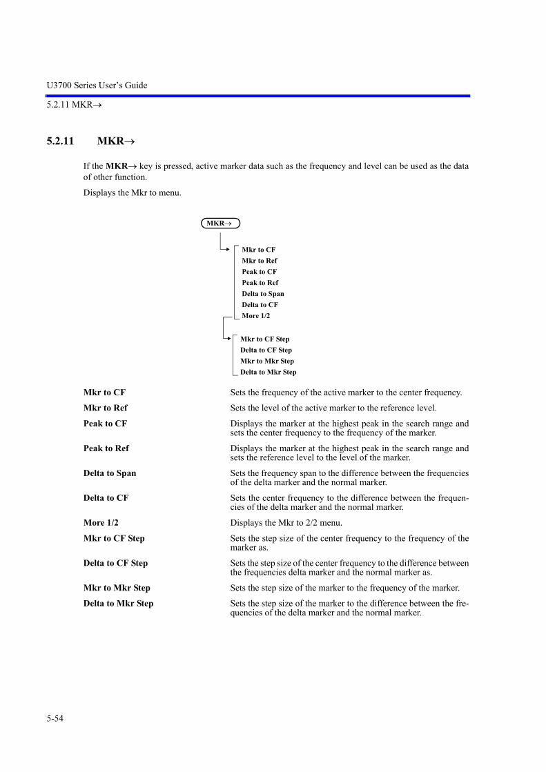
U3700 Series User’s Guide
5.2.11 MKR
5-54
5.2.11 MKR
If the MKR key is pressed, active marker data such as the frequency and level can be used as the dataof other function.
Displays the Mkr to menu.
Mkr to CF Sets the frequency of the active marker to the center frequency.
Mkr to Ref Sets the level of the active marker to the reference level.
Peak to CF Displays the marker at the highest peak in the search range andsets the center frequency to the frequency of the marker.
Peak to Ref Displays the marker at the highest peak in the search range andsets the reference level to the level of the marker.
Delta to Span Sets the frequency span to the difference between the frequenciesof the delta marker and the normal marker.
Delta to CF Sets the center frequency to the difference between the frequen-cies of the delta marker and the normal marker.
More 1/2 Displays the Mkr to 2/2 menu.
Mkr to CF Step Sets the step size of the center frequency to the frequency of themarker as.
Delta to CF Step Sets the step size of the center frequency to the difference betweenthe frequencies delta marker and the normal marker as.
Mkr to Mkr Step Sets the step size of the marker to the frequency of the marker.
Delta to Mkr Step Sets the step size of the marker to the difference between the fre-quencies of the delta marker and the normal marker.
MKR
Mkr to CF
Mkr to Ref
Peak to CF
Peak to Ref
Delta to Span
Delta to CF
More 1/2
Mkr to CF Step
Delta to CF Step
Mkr to Mkr Step
Delta to Mkr Step

U3700 Series User’s Guide
5.2.12 TG (Option)
5-55
5.2.12 TG (Option)
Displays the TG menu.
TG ON/OFF
ON: Turns on a tracking generator.
OFF: Turns off the tracking generator.
TG Level Sets the output level of the tracking generator.
Setting range0 dBm to -30 dBm (OPT77)0 dBm to -60 dBm (OPT76)
TG Level Offset ON/OFF Switches the TG level offset function ON and OFF.
ON: The offset level can be set in the range of 0 100.0 dB.The relationship between the displayed TG level, setTG level, and offset is as follows:Displayed TG level = Set TG level + Offset
OFF: Cancels the offset function.
TG Freq. Offset ON/OFF Adds the offset frequency to the TG output frequency.It functions with OPT76.
ON: The offset frequency can be set in the range of 0 Hz to+1 GHz and the resolution of approx. 1 kHz.The output frequency is up to 3 GHz even if adding theoffset frequency.
OFF: Cancels the offset function.
Normalize Displays the TG Normz menu.
Capture Normz Data Acquires the normalization data at the position of the referenceline.
Normalize Correction ON/OFF
ON: Normalizes the measurement data by using thenormalization data.Only trace A can be normalized.
OFF: Cancels the normalization function.
TG
TG ON/OFF
TG Level
TG Level Offset ON/OFF
TG Freq. Offset ON/OFF (OPT76)
Normalize
Reference Line ON/OFF
Capture Normz Data
Normalize Correction ON/OFF
Trace A/B/C
VSWR ON/OFF
Delta Ref Line ON/OFF
Reference Line ON/OFF

U3700 Series User’s Guide
5.2.12 TG (Option)
5-56
Trace A/B/C Selects the trace memory in which the data to be normalized isacquired and the normalization function is performed.
VSWR ON/OFF Displays a return loss and VSWR as marker values.
When performing a measurement, advance normalization withthe SWR bridge must be executed.
Refer to Section 4.4.7, “VSWR Measurement”.
ON: Displays Return Loss and VSWR.R.L = 20 log VSWR = (1+) / (1-)
OFF: Cancels the Return Loss and VSWR displays.
Delta Ref Line ON/OFF
ON: Sets the marker to ON and displays the level differenceto the reference line. (MK)
OFF: Hides the MK display.
Reference Line ON/OFF
ON: Displays the reference line and sets its display position.
OFF: Hides the reference line.

U3700 Series User’s Guide
5.2.13 FREQUENCY
5-57
5.2.13 FREQUENCY
Displays the Frequency menu.
Center Sets the center frequency.The frequency range is displayed by the center frequency and fre-quency span.
Start Sets the start frequency.The frequency range is displayed by the start frequency and stopfrequency.
Stop Sets the stop frequency.The frequency range is displayed by the start frequency and stopfrequency.
Frequency Offset ON/OFF Switches the frequency offset function ON and OFF.
ON: Sets the offset value and changes only the display of thefrequency by the offset value.(Displayed value of frequency = Set value + Offsetvalue)
OFF: Cancels the offset function.
CF Step Size AUTO/MNL Switches the step size between auto and manual settings when thecenter frequency is changed by the step key.
AUTO: Automatically sets the step size to 1/10 of the spanwidth.
MNL: Sets the step size manually.
FREQUENCY
Center
Start
Stop
Frequency Offset ON/OFF
CF Step Size AUTO/MNL
Channel Input
More 1/2
Signal Identification ON/OFF
Image Suppression ON/OFF
Freq Input Mode CALC/TABLE
Center CH ON/OFF
Start CH ON/OFF
Stop CH ON/OFF
Start CH Offset ON/OFF
Stop CH Offset ON/OFF
Channels Config
Edit Channel Formula
Edit Channel Table
Formula 1 ON/OFF
Formula 2 ON/OFF
Formula 3 ON/OFF
Insert Line
Delete Line
Table Init
(For the U3751, U3771, and U3772)

U3700 Series User’s Guide
5.2.13 FREQUENCY
5-58
Channel Input Displays the Channel menu.Uses the channel code instead of the frequency for the frequencysetting.
Freq Input Mode CALC/TABLESelects the channel input format.
CALC: Acquires a frequency from a channel number by usingthe mathematical formula.
TABLE: Acquires a frequency from a look-up table, whichcorresponds to a channel number.
Center CH ON/OFF Sets the center frequency input mode to the channel.
ON: Sets the channel code input mode.
OFF: Sets the frequency input mode.
Start CH ON/OFF Sets the start frequency input mode to the channel.
ON: Sets the channel code input mode.
OFF: Sets the frequency input mode.
Stop CH ON/OFF Sets the stop frequency input mode to the channel.
ON: Sets the channel code input mode.
OFF: Sets the frequency input mode.
Start CH Offset ON/OFF Switches the start frequency offset function ON and OFF whenthe channel input mode is set.
ON: Sets the offset value.Start frequency = Carrier frequency (Start channel) -start offset frequency
OFF: Cancels the offset function.
Stop CH Offset ON/OFF Switches the stop frequency offset function ON and OFF whenthe channel input mode is set.
ON: Sets the offset value.Stop frequency = Carrier frequency (Stop channel) +stop offset frequency
OFF: Cancels the offset function.
Channels Config Displays the Channels Config menu.

U3700 Series User’s Guide
5.2.13 FREQUENCY
5-59
Edit Channel Formula Displays the dialog box in which the mathematical formula toacquire the channel set frequency is defined.The set frequency is as follows:Carrier frequency = Origin + CH spacing * (CH No. - CH offset)
Edit Channel Table Displays the dialog box used to set the channel table.
Insert Line Inserts a line in the channel table.
Delete Line Deletes the line where the cursor is positioned.
Table Init Initializes the channel table.Clears all settings.

U3700 Series User’s Guide
5.2.13 FREQUENCY
5-60
Formula 1 ON/OFF
Formula 2 ON/OFF
Formula 3 ON/OFF
Sets the mathematical formula used in the channel input mode.This function is enabled when Freq Input Mode is set to CALC.
More 1/2 Displays the Frequency 2/2 menu.
Signal Identification ON/OFF (U3751/U3771/U3772)
ON: Turns on the Signal Identification function.Image signals shift on the screen but the signals do notmove in each sweep.
OFF: Cancels the Signal Identification function.
Image Suppression ON/OFF (U3751/U3771/U3772)
ON: Turns on the Image Suppression function.Detects image signals and deletes them from thedisplay.
OFF: Cancels the Image Suppression function.

U3700 Series User’s Guide
5.2.14 SPAN
5-61
5.2.14 SPAN
Span Sets the frequency span.The frequency range is displayed by the center frequency and fre-quency span.
Full Span Sets the frequency span to full span. (SPAN - 8 GHz)
Zero Span Sets the zero span mode at the center frequency.
Last Span Returns the frequency span to the previous value.
Peak Zoom Displays the marker at the highest peak in the targeted searchrange and sets the frequency of the marker to the center frequency.At this time, the frequency span is changed to 1/10 of the currentlyset value.
Auto Tune Searches the maximum signal level in the full band and capturesthe signal, then finally sets the frequency span to a value beforeAUTO TUNE starts. The reference level is set to the peak level of the searched signal.
ON: Starts AUTO TUNE.
OFF: Stops AUTO TUNE.
SPAN
Span
Full Span
Zero Span
Last Span
Peak Zoom
Auto Tune

U3700 Series User’s Guide
5.2.15 AMPLITUDE
5-62
5.2.15 AMPLITUDE
Displays the Level menu and enables the settings related to the amplitude display.
Ref Level Sets the reference level.
ATT Displays the Attenuation menu.
ATT AUTO/MNL Switches the attenuator function between auto and manual set-tings.
AUTO: Automatically sets the attenuator value according to thereference level.
MNL: Sets the attenuator value manually.
Min ATT Sets the minimum value of the attenuator. This setting is enabledonly when the attenuator is set manually.
Attenuation 0 dB Sets the attenuator to 0 dB.Displays the confirmation window before setting.This setting can be set by selecting OK with step keys and press-ing the unit key (ENTER).
AMPLITUDE
Ref Level
ATT
dB/div
Vertical Scale LIN/LOG
Units
Slide Screen ON/OFF
More 1/2
Ref Offset ON/OFF
Input Impedance 50/75
High Sensitivity ON/OFF
Correction Factor ON/OFF
Edit Corr Factor
Round Grid Values ON/OFF
ATT AUTO/MNL
Min ATT
Attenuation 0 dB
10 dB/div
5 dB/div
2 dB/div
1 dB/div
0.5 dB/div
dBm
dBmV
dBV
dBVemf
dBpW
Watts
Volts
Insert
Delete
Init Table

U3700 Series User’s Guide
5.2.15 AMPLITUDE
5-63
dB/div
10 dB/div Sets the LOG scale to 10 dB/div
5 dB/div Sets the LOG scale to 5 dB/div.
2 dB/div Sets the LOG scale to 2 dB/div.
1 dB/div Sets the LOG scale to 1 dB/div.
0.5 dB/div Sets the LOG scale to 0.5 dB/div.
Vertical Scale LIN/LOG
LIN: Displays waveform data on a linear scale.
LOG: Displays waveform data on a log scale.
Units
dBm Sets the display unit to dBm.
dBmV Sets the display unit to dBmV.
dBV Sets the display unit to dBV.
dBVemf Sets the display unit to dBVemf.
dBpW Sets the display unit to dBpW.
Watts Sets the display unit to Watts.
Volts Sets the display unit to Volts.
Slide Screen ON/OFF Scrolls the screen display up and down up to 100%.
ON: Enables the function. Enter the amount of the displayscrolls by using the knob, step keys or keypad.
OFF: Cancels the slide function.
More 1/2 Displays the Level 2/2 menu.
Ref Offset ON/OFF Switches the reference level offset function ON and OFF.
ON: The offset level can be set in the range of 0 to 100.0dB. The relationship among the displayed referencelevel, set reference level, and offset is as follows:Displayed reference level = Set reference level + Offset
OFF: Cancels the offset.
Input Impedance 50/75
50: Converts the power assuming that the input impedanceis 50 . This setting is the standard value that is 50.
75: Converts the power assuming that the input impedanceis 75 . The 6 dB conversion loss of the ZT-130NC 75/50 impedance converter is added automatically.
NOTE: For OPT11 and OPT15 (75 option), Input Impedance isfixed at 75 . This impedance cannot be changed to 50 .

U3700 Series User’s Guide
5.2.15 AMPLITUDE
5-64
High Sensitivity ON/OFF Switches the high-sensitivity input function ON and OFF.
ON: Turns on the built-in preamp. The preamp gain iscorrected at each frequency and it does not need to beconsidered in level measurements.
OFF: Turns off the built-in preamp.
Correction Factor ON/OFF
ON: Corrects the display level according to the correctiontable.
OFF: Cancels the correction based on the correction data.
Edit Corr Factor Displays the Corr Factor menu and the correction table.A frequency of up to 400 GHz and a level of 100 dB can be set.
Insert Inserts a line in the correction table.
Delete Deletes a line on which the cursor is positioned in the correctiontable.
Init Table Clears all settings in the correction table.
Round Grid Values ON/OFF
ON: Displays the vertical scale by rounding off the RefLevel setting value to integers.
OFF: Displays the vertical scale according to the Ref Levelsetting value.

U3700 Series User’s Guide
5.2.16 EXT CFG (Extended Configuration options)
5-65
5.2.16 EXT CFG (Extended Configuration options)
EXT CFG
Sweep Mode SGL/CNT
Trigger
Gated Sweep
Measuring Window
Limit Lines
Ref/Disp Lines
Zoom and Contexts
Source
Ext Trigger Level
Level
Slope NEG/POS
Delay
Free Run
Video
External
IF
Window HIDE/SHOW
Window Position
Window Width
Window Sweep ON/OFF
Pass/Fail ON/OFF
Line 1 ON/OFF
Line 1 ABV/BLW
Line 2 ON/OFF
Line 2 ABV/BLW
Pass/Fail Config
Limit Line EditX ABS/CF/FA
Shift X ON/OFF
Y ABS/REF/DL
Shift Y ON/OFF
Display Line ON/OFF
Limit Line 1/2
Delete Entry
Insert Entry
Table Init
Display Line ON/OFF
Reference Line ON/OFF
Gated Sweep ON/OFF
Source
Slope NEG/POS
Gate Delay
Gate Width
External
IF
(a)

U3700 Series User’s Guide
5.2.16 EXT CFG (Extended Configuration options)
5-66
Sweep Mode SGL/CNT Sets the sweep mode.
SGL: Sets the SINGLE mode.The sweep starts by pressing the START/STOP keyand stops.
CNT: Sets the CONTINUOUS mode.Repeats the sweep automatically by the next triggersignal after the sweep stops.
Trigger Displays the Trigger menu.
Source Displays the Trig Source menu.
Free Run Repeats the sweep automatically.
Video Synchronizes the sweep with the video signal and then starts thesweep.
External Synchronizes the sweep with the external trigger signal (EXT ter-minal) and then starts the sweep.
IF Synchronizes the sweep with the IF signal and then starts thesweep.
Ext Trigger Level Sets the trigger signal for the external trigger signal.
Level Sets the trigger level for the Video or IF trigger.
Slope NEG/POS Switches the trigger slope polarity.This setting is enabled only when the video trigger, external trig-ger or IF trigger is used.
NEG: Starts the sweep at the falling edge of a trigger.
POS: Starts the sweep at the rising edge of a trigger.
Delay Sets the delay time from a trigger point.
Freq vs Time ON/OFF
Frequency Pos
Context A/B
Graphic Z 1 Screen
Graphic Z 2 Screens
Freq Zoom
Freq vs Time
Time vs Time
Reset Context
Context A/B
Graphic Zoom 1 ON/OFF
Window Position
Window Width
Graphic Zoom 2 ON/OFF
Window Position
Window Width
Frequency Zoom ON/OFF
Zoom Position
Zoom Width
Context A/B
(a)

U3700 Series User’s Guide
5.2.16 EXT CFG (Extended Configuration options)
5-67
Gated Sweep Displays the Gated Sweep menu.
Gated Sweep ON/OFF Switches the gated sweep ON and OFF.
ON: Sweep is executed according to the currently set gateconditions (gate position and width).
OFF: Turns the gated sweep mode off.
Source Displays the Gate Source menu.
External: Performs sweep synchronizing with the external triggersignal.
IF: Performs sweep synchronizing with the IF signal.
Slope NEG/POS Switches the trigger slope polarity.
NEG: The sweep starts at the falling edge of a trigger signal.
POS: The sweep starts at the rising edge of a trigger signal.
Gate Delay Sets the delay time from a trigger point.Setting range: 0 sec to 1 sec
Gate Width Sets the gate time width.Setting range: 50 sec to 1 sec
Measuring Window Displays the Window menu.
Window HIDE/SHOW
HIDE: Hides the measuring window.
SHOW: Displays the measuring window.
Window Position Sets the center position of the window.
Window Width Sets the window width.
Window Sweep ON/OFF
ON: Performs the sweep only in the range set in themeasuring window.
OFF: Performs the sweep in the range of the set span width.
t1 t2 t3
input signal
gate signalt1: Gate Delayt2: Gate Width
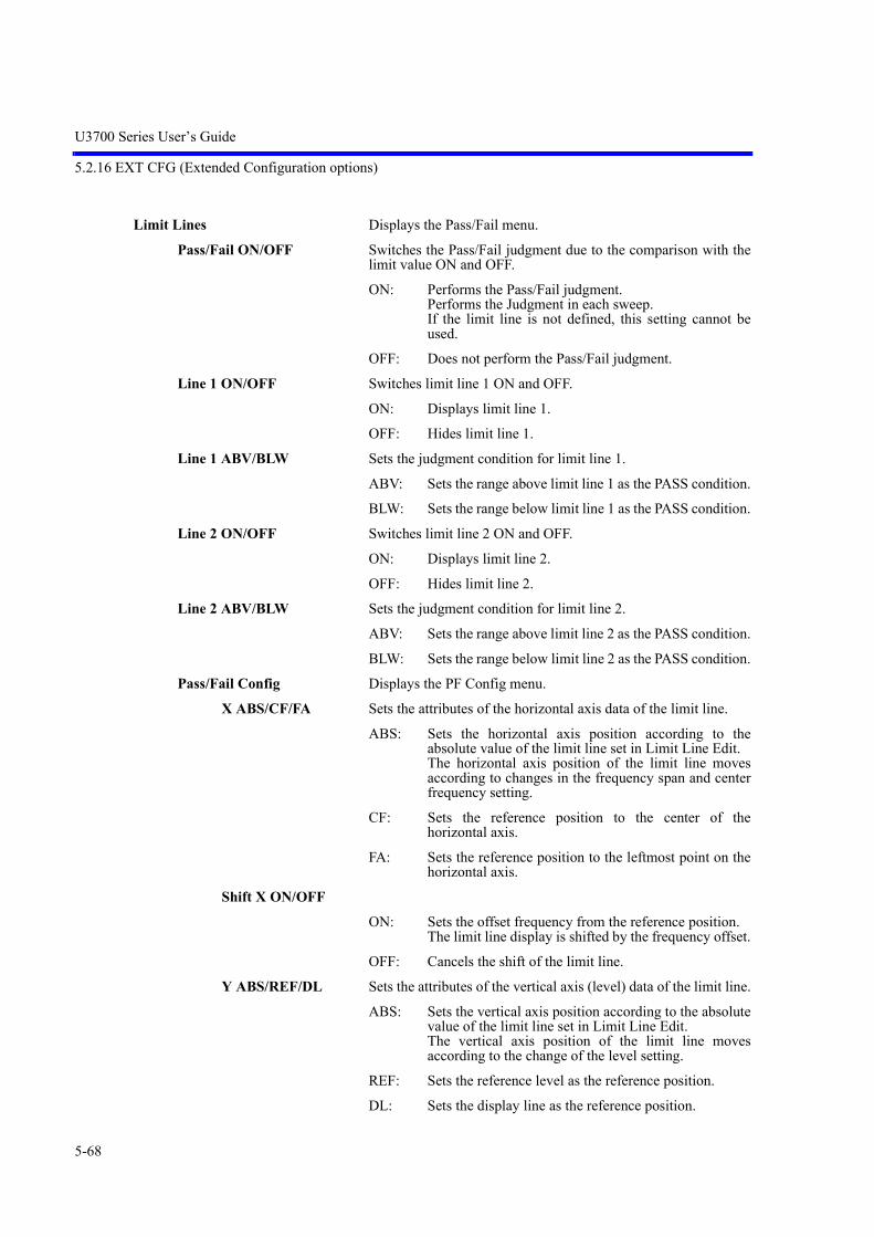
U3700 Series User’s Guide
5.2.16 EXT CFG (Extended Configuration options)
5-68
Limit Lines Displays the Pass/Fail menu.
Pass/Fail ON/OFF Switches the Pass/Fail judgment due to the comparison with thelimit value ON and OFF.
ON: Performs the Pass/Fail judgment.Performs the Judgment in each sweep.If the limit line is not defined, this setting cannot beused.
OFF: Does not perform the Pass/Fail judgment.
Line 1 ON/OFF Switches limit line 1 ON and OFF.
ON: Displays limit line 1.
OFF: Hides limit line 1.
Line 1 ABV/BLW Sets the judgment condition for limit line 1.
ABV: Sets the range above limit line 1 as the PASS condition.
BLW: Sets the range below limit line 1 as the PASS condition.
Line 2 ON/OFF Switches limit line 2 ON and OFF.
ON: Displays limit line 2.
OFF: Hides limit line 2.
Line 2 ABV/BLW Sets the judgment condition for limit line 2.
ABV: Sets the range above limit line 2 as the PASS condition.
BLW: Sets the range below limit line 2 as the PASS condition.
Pass/Fail Config Displays the PF Config menu.
X ABS/CF/FA Sets the attributes of the horizontal axis data of the limit line.
ABS: Sets the horizontal axis position according to theabsolute value of the limit line set in Limit Line Edit.The horizontal axis position of the limit line movesaccording to changes in the frequency span and centerfrequency setting.
CF: Sets the reference position to the center of thehorizontal axis.
FA: Sets the reference position to the leftmost point on thehorizontal axis.
Shift X ON/OFF
ON: Sets the offset frequency from the reference position.The limit line display is shifted by the frequency offset.
OFF: Cancels the shift of the limit line.
Y ABS/REF/DL Sets the attributes of the vertical axis (level) data of the limit line.
ABS: Sets the vertical axis position according to the absolutevalue of the limit line set in Limit Line Edit.The vertical axis position of the limit line movesaccording to the change of the level setting.
REF: Sets the reference level as the reference position.
DL: Sets the display line as the reference position.

U3700 Series User’s Guide
5.2.16 EXT CFG (Extended Configuration options)
5-69
Shift Y ON/OFF
ON: Sets the offset (dB) of the vertical axis from the limitline.The limit line display is shifted by the level offset.
Display Line ON/OFF
ON: Displays the display line.Sets the position of the display line.
OFF: Hides the display line.
Limit Line Edit Displays the Limit Line menu.
Limit Line 1/2
1: Edits limit line 1.
2: Edits limit line 2.
Delete Entry Deletes a line on which the cursor is positioned in the limit linetable.
Insert Entry Inserts a line in the limit line table.
Table Init Clears all settings in the limit line table.
Ref/Disp Lines Displays the Display menu.
Display Line ON/OFF Switches the display of the display line, which is used as the ref-erence line when trace levels are compared, between ON andOFF.
ON: Displays the display line.
OFF: Hides the display line.
Reference Line ON/OFF Switches the display of the reference line, which is used as the ref-erence to display level data in relative value, between ON andOFF.
ON: Displays the reference line.The reference line position can be changed.
OFF: Hides the reference line.
Zoom and Contexts Displays the Zoom Contexts menu.
Graphic Z 1 Screen Displays the G Zoom 1 Screen menu.
Graphic Zoom 1 ON/OFF
ON: Zooms in the area selected by the window.
OFF: Cancels the zoom-in display.
Window Position Sets the center position of the window.
Window Width Sets the window width.
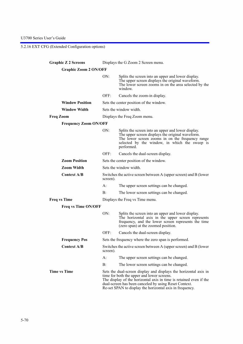
U3700 Series User’s Guide
5.2.16 EXT CFG (Extended Configuration options)
5-70
Graphic Z 2 Screens Displays the G Zoom 2 Screen menu.
Graphic Zoom 2 ON/OFF
ON: Splits the screen into an upper and lower display.The upper screen displays the original waveform.The lower screen zooms in on the area selected by thewindow.
OFF: Cancels the zoom-in display.
Window Position Sets the center position of the window.
Window Width Sets the window width.
Freq Zoom Displays the Freq Zoom menu.
Frequency Zoom ON/OFF
ON: Splits the screen into an upper and lower display.The upper screen displays the original waveform.The lower screen zooms in on the frequency rangeselected by the window, in which the sweep isperformed.
OFF: Cancels the dual-screen display.
Zoom Position Sets the center position of the window.
Zoom Width Sets the window width.
Context A/B Switches the active screen between A (upper screen) and B (lowerscreen).
A: The upper screen settings can be changed.
B: The lower screen settings can be changed.
Freq vs Time Displays the Freq vs Time menu.
Freq vs Time ON/OFF
ON: Splits the screen into an upper and lower display.The horizontal axis in the upper screen representsfrequency, and the lower screen represents the time(zero span) at the zoomed position.
OFF: Cancels the dual-screen display.
Frequency Pos Sets the frequency where the zero span is performed.
Context A/B Switches the active screen between A (upper screen) and B (lowerscreen).
A: The upper screen settings can be changed.
B: The lower screen settings can be changed.
Time vs Time Sets the dual-screen display and displays the horizontal axis intime for both the upper and lower screens.The display of the horizontal axis in time is retained even if thedual-screen has been canceled by using Reset Context.Re-set SPAN to display the horizontal axis in frequency.

U3700 Series User’s Guide
5.2.16 EXT CFG (Extended Configuration options)
5-71
Reset Context Cancels the dual-screen display.
Context A/B Switches the active screen between A (upper screen) and B (lowerscreen).
A: The upper screen settings can be changed.
B: The lower screen settings can be changed.

U3700 Series User’s Guide
5.2.17 CPL (Coupled function)
5-72
5.2.17 CPL (Coupled function)
Sets the resolution bandwidth (RBW), video bandwidth (VBW), and sweep time.
RBW AUTO/MNL Switches the RBW between auto and manual settings.
AUTO: Automatically sets the optimum RBW according to thefrequency span setting.
MNL: The RBW can be set arbitrarily.
VBW AUTO/MNL Switches the VBW between auto and manual settings.
AUTO: Automatically sets the optimum VBW according to theRBW setting.
MNL: The VBW can be set arbitrarily.
Sweep Time AUTO/MNL Switches the sweep time between auto and manual settings.
AUTO: Automatically sets the optimum sweep time accordingto the frequency span, RBW, and VBW settings.
MNL: The sweep time can be set arbitrarily.
EMC Displays the EMC menu. (OPT28)
EMC Filter ON/OFF ON: Uses the EMC filter.
OFF: Cancels the EMC filter mode.
RBW Auto Sets the resolution bandwidth automatically according to the mea-surement frequency band.
RBW 200 Hz Sets the resolution bandwidth to 200 Hz.
RBW 9 kHz Sets the resolution bandwidth to 9 kHz.
RBW 120 kHz Sets the resolution bandwidth to 120 kHz.
RBW 1 MHz Sets the resolution bandwidth to 1 MHz.
CPL
RBW AUTO/MNL
VBW AUTO/MNL
Sweep Time AUTO/MNL
EMC
All Auto
More 1/2
SPAN/RBW ON/OFF
VBW/RBW ON/OFF
PLL BW
EMC Filter ON/OFF
RBW Auto
RBW 200 Hz
RBW 9 kHz
RBW 120 kHz
RBW 1 MHz
Auto
Medium
Narrow

U3700 Series User’s Guide
5.2.17 CPL (Coupled function)
5-73
All Auto Automatically sets the optimum RBW, VBW, and sweep timeaccording to the frequency span setting.
More 1/2 Displays the Coupling 2/2 menu.
SPAN/RBW ON/OFF Switches the RBW vs frequency span function between the autoand manual settings.This setting is enabled only when the RBW is set to AUTO.
ON: The frequency vs RBW span ratio can be changed.
OFF: The frequency/RBW span value is fixed to 100.
VBW/RBW ON/OFF Switches the VBW vs RBW function between the auto and man-ual settings.This setting is enabled only when the VBW is set to AUTO.
ON: The VBW vs RBW ratio can be changed.
OFF: The VBW/RBW value is fixed to 1.
PLL BW Displays the PLL Band Width menu. (OPT 70)Sets the band-pass filter width in the PLL circuit.
Auto Sets the filter width automatically so that the optimum phasenoise characteristics corresponding to the frequency span can beobtained.
Medium Sets the filter width to Medium.
Narrow Sets the filter width to Narrow. The phase noise around 300 kHz to 2 MHz away from the carrieris improved.
CAUTION: When PLL Band Width is set to Medium or Narrow,the phase noise may deteriorate depending on the setfrequency span. In such a case, set to AUTO.


U3700 Series User’s Guide
6. OVERVIEW OF REMOTE CONTROL
6-1
6. OVERVIEW OF REMOTE CONTROL
This chapter describes the overview of the remote control system.
6.1 Remote Control
6.1.1 Types of Systems
The following two types of remote control systems can be configured, depending on the interface:
6.1.2 Selecting the Command Set
Either the AT (Advantest) command set or SCPI command set is selected as a command set used for pro-gramming in this instrument.
Both command sets cannot be used together.
Press SYSTEM, Remote Control, and Parser AT/SCPI.
Interface Overview
GPIB(Talker/Listener mode)
The external controller controls the U3700 Series and other devices, which are connected with each other through the GPIB, in this system.For more information, refer to “6.2 GPIB Remote Control Sys-tem” (on page 6-2).
LAN
The external controller controls the U3700 Series and other devices, which are connected with each other through LAN, in this system.For more information, refer to “6.3 LAN Remote Control System” (on page 6-6).

U3700 Series User’s Guide
6.2 GPIB Remote Control System
6-2
6.2 GPIB Remote Control System
The GPIB (General Purpose Interface Bus) that is compliant with IEEE standards 488.1-1978 and 488.2-1987 comes standard with this instrument so that remote control can be performed from the external control-ler.
The following describes how to control this instrument by using the GPIB remote control function.
6.2.1 What is the GPIB?
The GPIB (General Purpose Interface Bus) is a high performance bus that integrates computers and mea-suring instruments.
The GPIB operations are defined by IEEE standard 488.1-1978. Since the GPIB is a bus structure inter-face, the specific device can be identified by assigning a unique device address to each device. Up to 15devices can be connected to a bus in parallel. A GPIB device includes at least one of the following func-tions:
• TalkerA device that is specified to send data to the bus is called a “talker”. Only one device operates as anactive talker on a GPIB bus.
• ListenerA device that is specified to receive data from the bus is called a “listener”. Two or more active lis-tener devices exist on a GPIB bus.
• ControllerA device that specifies talkers and listeners is called a “controller”. On a GPIB bus, only one deviceoperates as an active controller. Of these controllers, a device that can control IFC and REN messagesis called the “system controller”.Only one system controller is permitted on a GPIB bus. If there are two or more controllers on a bus,the system controller becomes the active controller at the time of system startup and the other deviceswith controller capability act as addressable devices.To set another controller as the active controller, use Take Control (TCT) interface messages. At thistime, this controller becomes a non-active controller.The controller controls the entire system by sending interface or device messages to each measuringinstrument. The roles of these messages are shown below.
• Interface message: Controls the GPIB bus.
• Device message: Controls the measuring instruments.

U3700 Series User’s Guide
6.2.2 Setting up the GPIB
6-3
6.2.2 Setting up the GPIB
1. GPIB connectionThe standard GPIB connection is shown below. Secure the GPIB connector with two screws.
Figure 6-1 GPIB Connection
Note the following when using the GPIB interface:• Connect the GPIB cable to the GP-IB 1 connector on the rear panel of this instrument.• The total cable length of the GPIB cable used in one bus system should not be longer than 2 m
{the number of connected devices (the GPIB controller is counted as one device)}.The total cable length should be 20 m or less.
• Up to 15 devices can be connected to one bus system.• There is no restriction in how cables are connected. However, no more than three GPIB
connectors should be stacked on one device. If four or more GPIB connectors are stacked, thejoints of the connectors may break because excessive force is applied to them.
For example, a system consisting of five devices can use cables of up to 10 m (2 m/device 5devices = 10 m) length. Cable lengths can be allocated freely unless the total cable length exceedsthe permitted maximum length. If 10 or more devices are connected, however, some devicesshould be connected with cables less than 2 m so that the total cable length does not exceed 20 m.
• Ensure that all devices on the bus are turned on. If any device on the bus is not turned on, thesystem may not operate correctly.
• Turn off all devices on the bus before connecting or disconnecting GPIB cables.
2. GPIB address settingGPIB addresses should be set by pressing the System key and selecting GPIB Address.

U3700 Series User’s Guide
6.2.3 GPIB Bus Functions
6-4
6.2.3 GPIB Bus Functions
6.2.3.1 GPIB Interface Functions
6.2.3.2 Responses to Interface Messages
The responses of this instrument to interface messages described in this section are defined in IEEE stan-dards 488.1-1978 and 488.2-1987.
For more information on how to send interface messages to this instrument, refer to the operation manualof the controller used.
1. Interface clear (IFC)This message is directly sent to this instrument through a signal line.This instrument stops the operation of the GPIB bus by using this message. Though all input/outputis stopped, the I/O buffer is not cleared (it is cleared by DCL).
2. Remote enable (REN)This message is directly sent to this instrument through a signal line.If this instrument is specified as a listener when this message is TRUE, it enters the remote state.This instrument remains in this state until it receives a GTL command, REN changes to FALSE, orthe LOCAL key is pressed.This instrument ignores all received data when it is in the local state.
Table 6-1 GPIB Interface Functions
Code Description
SH1 Source handshake function
AH1 Accepter handshake function
T6 Basic talker function, serial polling function, listener-specified talker cancel function
TE0 No extended talker function
L4 Basic listener function, talker-specified listener cancel function
LE0 No extended listener function
SR1 Service request function
RL1 Remote function, local function, local lockout function
PP0 No parallel polling function
DC1 Device clear function
DT1 Device trigger function
DT0 No device trigger function
C0 No system controller function
E1 Using the open-collector bus driver

U3700 Series User’s Guide
6.2.3 GPIB Bus Functions
6-5
When it is in the remote state, this instrument ignores all key entry except the LOCAL key.When it is in the local lockout state (referred to as “Local lockout (LLO)”), this instrument ignoresall key entry.
3. Serial poll enable (SPE)When receiving this message from a controller, this instrument enters the serial polling mode.When this instrument specified as a talker in this mode, it sends status bytes instead of ordinary mes-sages. This mode continues until this instrument receives a serial polling disable (SPD) message oran IFC message.When this instrument is sending a service request (SRQ) message to the controller, bit6 (RQS bit) ofresponse data is set to 1 (TRUE). After transmission is completed, RQS bit is set to 0 (FALSE). Ser-vice request (SRQ) messages are directly sent through a signal line.
4. Device clear (DCL)When receiving DCL, this instrument performs the following operations:• Clearing the input and output buffers• Resetting the syntax analysis, execution control, and response data generation units• Canceling all the commands that impede the remote command to be executed next• Canceling any commands that are waiting for other parameters
The following operations are not executed:• Changing data that is set or stored in this instrument• Interrupting front panel operations• Affecting or interrupting the operations of this instrument in mid-execution• Changing status byte excluding MAV (MAV is set to 0 as a result of clearing the output buffer)
5. Selected device clear (SDC)Performs the same operation as DCL. However, SDC is executed only when this instrument is a lis-tener.In other cases, it is ignored.
6. Go to local (GTL)This message sets this instrument to the local state. In the local state, all front panel operations areenabled.
7. Local lockout (LLO)This message sets this instrument to the local lockout state. When this instrument enters the remotestate from this state, all front panel operations are disabled (In the ordinary remote state, front paneloperation can be performed by pressing the LOCAL key).In this case, this instrument can be set to the local state by any of the following two methods:• Setting the REN message to FALSE (The local lockout state is also canceled)• Turning off and turning on the power

U3700 Series User’s Guide
6.3 LAN Remote Control System
6-6
6.3 LAN Remote Control System
The LAN (Local Area Network) interface that is compliant with IEEE standard 802.3 is included as standardwith this instrument so that this instrument can be controlled remotely through socket communication by theexternal controller.
The controlling method using the LAN remote control function is described below.
6.3.1 Setting up the LAN
1. LAN connectionThe standard LAN setup is shown below. To allow communication through the LAN between an ex-ternal controller and this instrument or other devices, connect them with 10BASE-T LAN cable andRJ45 connectors. To directly connect this instrument and an external controller with a LAN cable, usea LAN cable (cross over cable) and connect as shown in Table 6-2. To connect this instrument andother devices (excluding an external controller) with a LAN, use an external device designed to con-nect devices that has two or more LAN interfaces such as an Ethernet hub. The LAN cable used inthis case is connected as shown in Table 6-3.
Figure 6-2 LAN Setup
External controller LAN cable
U3700 series rear panel
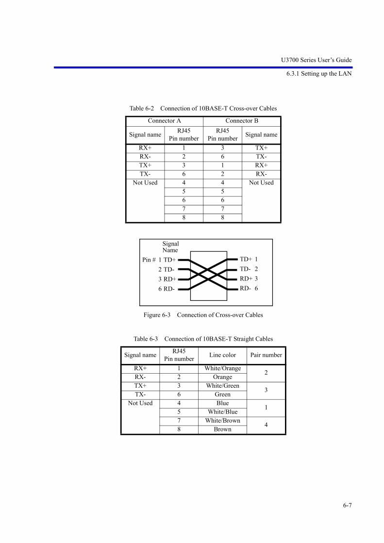
U3700 Series User’s Guide
6.3.1 Setting up the LAN
6-7
Figure 6-3 Connection of Cross-over Cables
Table 6-2 Connection of 10BASE-T Cross-over Cables
Connector A Connector B
Signal name RJ45 Pin number
RJ45 Pin number Signal name
RX+ 1 3 TX+RX- 2 6 TX-TX+ 3 1 RX+TX- 6 2 RX-
Not Used 4 4 Not Used5 56 67 78 8
Table 6-3 Connection of 10BASE-T Straight Cables
Signal name RJ45 Pin number Line color Pair number
RX+ 1 White/Orange2
RX- 2 OrangeTX+ 3 White/Green
3TX- 6 Green
Not Used 4 Blue1
5 White/Blue7 White/Brown
48 Brown
TD+ 1TD- 2RD+ 3RD- 6
Pin # 1 TD+2 TD-3 RD+6 RD-
Signal Name

U3700 Series User’s Guide
6.3.2 Setting the IP Address
6-8
6.3.2 Setting the IP Address
Press SYSTEM, Remote Control, and LAN IP Address.
1. Setting the IP Address ManuallyEnter a check mark into the "Use the following IP address" check box.
Click the Apply button and press Hz.
2. Obtaining the IP Address AutomaticallyEnter a check mark into the "Obtain an IP address automatically" check box.
Click the Apply button and press Hz.
IP AddressSubnet MaskDefault Gateway
Set the above items.

U3700 Series User’s Guide
6.3.3 Control from a Controller
6-9
After an IP address is obtained, the IP address is displayed in the window.
6.3.3 Control from a Controller
To control this instrument from an external controller, a port number for socket communication is required.The port number “5025” is assigned for socket communication in the remote state in this instrument. Towrite a program for socket communication, a library for network connection with the TCP/IP protocol isrequired. The library differs depending on the environment, such as the OS of the external controller. Inthe Windows OS environment, for example, WinSock is provided.
After completing the network connection with this instrument, send the "REN" command to this instru-ment to enable the remote control. (At this time, the remote lamp on the front panel of this instrument is on.) After that, this instrument can be remotely controlled by sending the same commands as the GPIB.
Some of the functions available in the GPIB remote control system are specific to the GPIB bus, such asservice requests, and cannot be used in the LAN remote control system.

U3700 Series User’s Guide
6.4 Message Exchanging Protocol
6-10
6.4 Message Exchanging Protocol
This instrument receives program messages from the controller or other devices through the GPIB bus orLAN and generates a response. Program messages include commands, queries (which are commands that askfor a response) and data.
6.4.1 Buffers
This instrument has two buffers.
1. Input bufferThis buffer temporarily stores data to analyze commands.(1024-byte length)The input buffer can be cleared by the following two methods:• Turning the power on• Executing a DCL or SDC
2. Output bufferThis buffer stores data until the data is read by the controller.(1024-byte length)The output buffer can be cleared by the following two methods:• Turning the power on• Executing a DCL or SDC
6.4.2 Message Exchange
When other controllers or devices receive messages from this instrument, the following items must beobserved:
• Generating a response in reply to a query (Refer to “Parser”).
• Generating responses in the order queries are executed (Refer to “Generating response data”).
Parser
• The parser receives command messages from the input buffer in the order queries are received, exe-cutes syntax analysis, and determines what operations are to be executed by the commands received.
Generating response data
• When the parser executes a query, this instrument generates data on the output buffer as its response (that is, a query must be sent immediately before outputting data).

U3700 Series User’s Guide
6.5 Command Syntax
6-11
6.5 Command Syntax
This chapter describes the command syntax.
6.5.1 Command Syntax
The command syntax is defined in the following format:
1. HeaderTwo types of header are available: the common command header and the simple header. The commoncommand header starts with an asterisk (*).The simple header is a functionally independent commandthat has no hierarchical structure.If a question mark (?) is attached immediately after a header, it becomes a query command.
2. SpacesSpaces may be used to separate headers from data to ease readability.
3. DataWhen the command requires more than one data item, list these data items by delimiting them withcommas (,). A space may be inserted before or after the comma (,). For more information on datatypes, refer to Section 6.5.2 “Data Formats.”
4. Writing more than one commandYou can write multiple commands by delimiting them with semicolons (;) in one line.
DataHeader <Space (space characters)>

U3700 Series User’s Guide
6.5.2 Data Formats
6-12
6.5.2 Data Formats
This instrument uses the following data formats for the input and output data.
1. Numeric dataThere are three formats for numeric data as shown below. When entering numeric values for this instrument, any format may be used. Depending on the command, a unit may be attached to the entered numeric value.• Integer type: NR1 format
• Fixed-point type: NR2 format
• Floating-point type: NR3 format
2. UnitAvailable units are listed below:
Unit Exponential DescriptionGZ 109 Frequency
MZ 106 Frequency
KZ 103 Frequency
HZ 100 Frequency
VOLT 100 Voltage
MV 10-3 Voltage
UV 10-6 Voltage
NV 10-9 Voltage
MW 10-3 Power
DB 100 dB description
MA 10-3 Current
SC 100 Second
MS 10-3 Second
US 10-6 Second
PER 100 Percentage
% 100 Percentage
Number[Sign]
.[Sign] Number Number
. Number
Number
Number[Sign]
E/e [Sign]

U3700 Series User’s Guide
6.5.3 Status Byte
6-13
6.5.3 Status Byte
This instrument has a layered status register structure that is compliant with IEEE standard 488.2-1987,and can send various statuses of this instrument to the controller. This section describes the behavioralmodel of status bytes and allocation of events.
1. Status RegisterThis instrument adopts the model of the status registers defined in IEEE standard 488.2-1987. Thestatus registers consist of the condition register, event register, and enable register.
a. Condition RegisterThe condition register is always monitoring the status of this instrument. That is, this register alwaysretains the latest status of this instrument. However, data cannot be both written into and read fromthe condition register because the condition register retains data as internal information.
b. Event RegisterThe event register latches and retains statuses from the condition register (or retains changes).Once this register is set, the setting value is kept until it is read by a query or cleared by *CLS.Data cannot be written into the event register.
c. Enable RegisterThe enable register specifies which bit in the event register is set as an effective status to generate asummary. The enable register is ANDed with the event register and the OR of the result is generatedas a summary. The summary is written into the status byte register.Data can be written into the enable register.This instrument uses the following three types of status registers:• Status byte register• Standard event register• Standard operation status registerThe arrangement of the status register in this instrument is shown in Figure 6-4.The details of the status register are shown in Figure 6-5.
0
1
n-1
n
0
1
n-1
n
.
.
.
.
.
0
1
n-1
n
SummaryOR
&
&
&
&
.
.
.
.
.
.
.
.
.
.
Condition register
Event register
Enable register
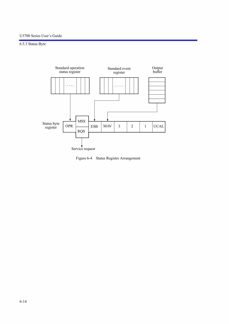
U3700 Series User’s Guide
6.5.3 Status Byte
6-14
Figure 6-4 Status Register Arrangement
UCAL
Standard event register
MAV
Standard operation status register
ESB 3 12
Output buffer
. . . . .
OPRMSS
RQS
. . . . .
Service request
Status byteregister
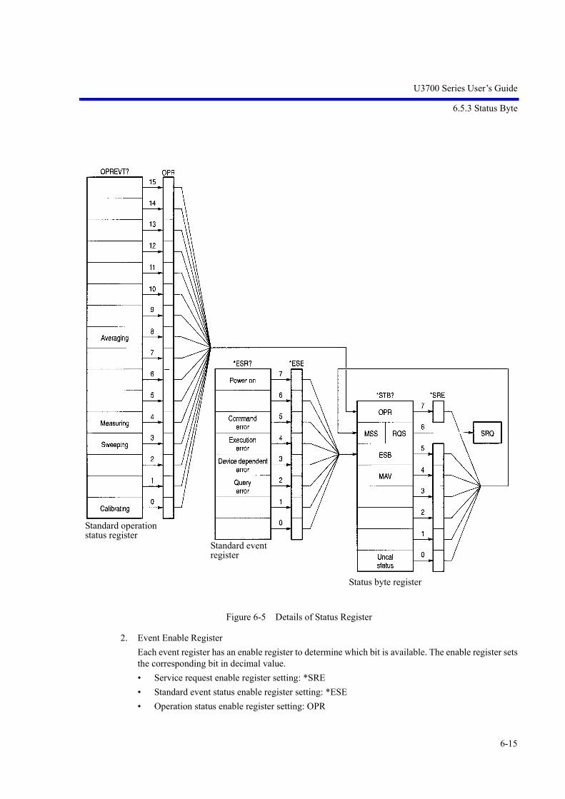
U3700 Series User’s Guide
6.5.3 Status Byte
6-15
Figure 6-5 Details of Status Register
2. Event Enable RegisterEach event register has an enable register to determine which bit is available. The enable register setsthe corresponding bit in decimal value.• Service request enable register setting: *SRE• Standard event status enable register setting: *ESE• Operation status enable register setting: OPR
Standard operationstatus register
Standard event register
Status byte register

U3700 Series User’s Guide
6.5.3 Status Byte
6-16
3. Standard Operation Status RegisterAssignment in the standard operation status register is listed below:
4. Status Byte RegisterThe status byte register summarizes the information from the status register. A summary of this statusbyte register is sent to the controller as a service request. Therefore, the status byte register operatesslightly differently than the status register structure. This section describes the status byte register.The structure of the status byte register is shown in Figure 6-6.
Figure 6-6 Structure of the Status Byte Register
This status byte register follows the status register except for the following three points:• The summary of the status byte register is written to bit6 of the status byte register.• Bit6 of the enable register is always valid and cannot be changed.• Bit6 (MSS) of the status byte register writes the RQS of the service request.
Bit Functional definition Description
15 to 9 Always 0
8 Averaging Set to 1 when averaging is complete.
7 to 5 Always 0
4 Measuring Set to 1 when sequence measuring is complete.
3 Sweeping Set to 1 when sweeping is complete
2 to 1 Always 0
0 Calibrating Set to 1 when correction data acquisition is completed.

U3700 Series User’s Guide
6.5.3 Status Byte
6-17
This register responds to the serial polling from the controller. When the register responds to the serialpolling, bit0 to bit5, bit7, and the RQS of the status byte register are read, and then the RQS is resetto 0. No other bits are cleared until each factor is set to 0.The status byte register, RQS, and MSS can be cleared by executing “CLS” and “S2”. Consequently,the SRQ line is set to FALSE.The meaning of each bit in the status byte register is shown below:
Bit Functional definition Description
7 OPR A summary of the standard operation status register.
6 MSS The summary bit of the entire status data structure. RQS is set to TRUE when MSS is set to 1 in the status byte regis-ter. MSS cannot be read during serial polling but it is 1 when RQS is 1.To read the MSS, use the common command *STB?.MSS, bit0 to bit5, and bit7 of the status byte register are read by *STB?. In this case, the status byte register and MSS are not cleared.MSS is not set to 0 until all the unmasked factors in the status register structure are cleared.
5 ESB A summary of the standard event register.
4 MAV The summary bit of the output buffer.Not uses in this instrument.
3 to 1 Always 0
0 UCAL Set to 1 if a signal level error occurs because the sweep is too fast.
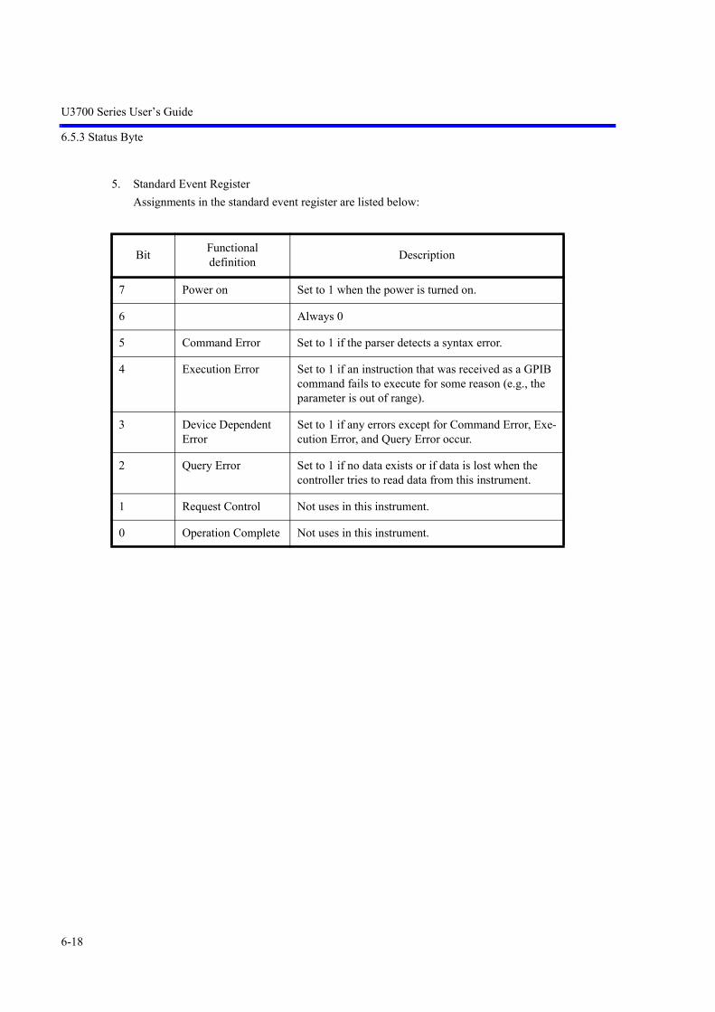
U3700 Series User’s Guide
6.5.3 Status Byte
6-18
5. Standard Event RegisterAssignments in the standard event register are listed below:
Bit Functional definition Description
7 Power on Set to 1 when the power is turned on.
6 Always 0
5 Command Error Set to 1 if the parser detects a syntax error.
4 Execution Error Set to 1 if an instruction that was received as a GPIB command fails to execute for some reason (e.g., the parameter is out of range).
3 Device Dependent Error
Set to 1 if any errors except for Command Error, Exe-cution Error, and Query Error occur.
2 Query Error Set to 1 if no data exists or if data is lost when the controller tries to read data from this instrument.
1 Request Control Not uses in this instrument.
0 Operation Complete Not uses in this instrument.

U3700 Series User’s Guide
6.6 GPIB Remote Programming
6-19
AT Command Pages AT Command Pages
6.6 GPIB Remote Programming
This section shows the AT commands in each function:
• Command codeAn asterisk "*" indicates a function that numeric or character strings data follows after the code.Numeric data and "ON" can be omitted from [ ].
• Output format
• A comma "," indicates that two or more data are output.
• ON or OFF indicates that 1 or 0 is output.
• Frequency is output in Hz and time is output in sec.
• Level data is output in the currently set display unit.
6.7 AT Command Index
<n>AVG*|<n>GR .................................. 6-31<n>AVG*|<n>GS ................................... 6-31<n>B ....................................................... 6-30<n>G ....................................................... 6-30<n>GC .................................................... 6-31<n>GCNT ............................................... 6-31<n>GP ..................................................... 6-31<n>GSGL ................................................ 6-31<n>MAX ................................................. 6-30<n>MIN .................................................. 6-30<n>NORM .............................................. 6-53<n>PAVG ............................................... 6-31<n>PGC .................................................. 6-31<n>PGCNT ............................................. 6-31<n>PGP ................................................... 6-31<n>PGSGL ............................................. 6-31<n>V ....................................................... 6-30<n>W ...................................................... 6-30% | PER ................................................... 6-54*CLS ....................................................... 6-51*ESE ....................................................... 6-51*ESR ....................................................... 6-51*IDN ....................................................... 6-52*OPT ....................................................... 6-52*SRE ....................................................... 6-51*STB ....................................................... 6-51*TST ....................................................... 6-52AA ........................................................... 6-27ABA ........................................................ 6-31ABB ........................................................ 6-31
ABC ........................................................ 6-31ACP ......................................................... 6-44ACPCBW ................................................ 6-44ACPLOAD .............................................. 6-44ACPNQST .............................................. 6-44ACPREF ................................................. 6-44ACPSAVE .............................................. 6-44ACPSCR ................................................. 6-44ACPTM ................................................... 6-44ADG ........................................................ 6-44ADLA ..................................................... 6-31AL ........................................................... 6-28AMMF .................................................... 6-41AMMOD ................................................. 6-41ANNOT .................................................. 6-51AR ........................................................... 6-53AS ........................................................... 6-29AT ........................................................... 6-27ATMIN ................................................... 6-27AUNITS .................................................. 6-27BA ........................................................... 6-28BAA ........................................................ 6-31BAB ........................................................ 6-31BAC ........................................................ 6-31BDLB ...................................................... 6-31BMP ........................................................ 6-50CA ........................................................... 6-25CALCA ................................................... 6-30CALCB ................................................... 6-30CALCC ................................................... 6-30

U3700 Series User’s Guide
6.7 AT Command Index
6-20
CAPND ................................................... 6-53CARRBS ................................................. 6-44CC ........................................................... 6-48CDB ........................................................ 6-39CF ............................................................ 6-25CFCH ...................................................... 6-25CFCHON ................................................ 6-25CHCALC1 .............................................. 6-26CHCALC2 .............................................. 6-26CHCALC3 .............................................. 6-26CHCON1 ................................................ 6-26CHCON2 ................................................ 6-26CHCON3 ................................................ 6-26CHTDEL ................................................. 6-26CHTIN .................................................... 6-26CLALL .................................................... 6-47CLATT .................................................... 6-48CLCREF ................................................. 6-48CLDREF ................................................. 6-48CLFREF .................................................. 6-48CLGAIN ................................................. 6-47CLPBW ................................................... 6-47CLRBW .................................................. 6-47CLSREF .................................................. 6-48CN ........................................................... 6-42CN0 ......................................................... 6-42CN1 ......................................................... 6-42CN2 ......................................................... 6-42CN3 ......................................................... 6-42CNPOS .................................................... 6-42CNPOSA ................................................. 6-42CNRES .................................................... 6-42CORS ...................................................... 6-28CORS OFF .............................................. 6-28CORS ON ............................................... 6-28COUNT ................................................... 6-42COVR ..................................................... 6-28COVR OFF ............................................. 6-28COVR ON ............................................... 6-28CP ............................................................ 6-38CR ........................................................... 6-47CR OFF ................................................... 6-27CR ON .................................................... 6-27CRDEL ................................................... 6-27, 6-47CRIN ....................................................... 6-27, 6-47CS ............................................................ 6-25CSBSDEL ............................................... 6-44CSBSIN .................................................. 6-44CTXTSEL ............................................... 6-34DB ........................................................... 6-54DBEMF ................................................... 6-54
DBM ....................................................... 6-54DBMV .................................................... 6-54DBPW ..................................................... 6-54DBUV ..................................................... 6-54DC0 ......................................................... 6-39DC1 ......................................................... 6-39DC2 ......................................................... 6-39DD ........................................................... 6-27DEL ......................................................... 6-48DET ......................................................... 6-32DETA<n> ............................................... 6-32DETAVG ................................................ 6-32DETB ...................................................... 6-32DETC ...................................................... 6-32DLIM0 .................................................... 6-51DLIM1 .................................................... 6-51DLIM2 .................................................... 6-51DLIM5 .................................................... 6-51DLN ........................................................ 6-34DLN OFF ................................................ 6-34DLN ON ................................................. 6-34DS|MTSP ................................................ 6-37DUALCH ................................................ 6-35DUALCHINIT ........................................ 6-35DY ........................................................... 6-38E .............................................................. 6-54EMCON|EMCDET ................................. 6-47FA ........................................................... 6-25FACH ...................................................... 6-25FACHO ................................................... 6-25FACHON ................................................ 6-25FACHOON ............................................. 6-25FB ............................................................ 6-25FBCH ...................................................... 6-25FBCHO ................................................... 6-25FBCHON ................................................ 6-26FBCHOON ............................................. 6-25FC ............................................................ 6-48FILEFORMAT ....................................... 6-48FILEMEDIA ........................................... 6-48FINPMD ................................................. 6-25FMMEAS ................................................ 6-41FMMODF ............................................... 6-41FMMODFY ............................................ 6-41FO ........................................................... 6-25FO ON|OFF ............................................ 6-25FORM1 ................................................... 6-32FORM2 ................................................... 6-32FORM3 ................................................... 6-32FORM4 ................................................... 6-32FS ............................................................ 6-25

U3700 Series User’s Guide
6.7 AT Command Index
6-21
FTPOS .................................................... 6-34FX ........................................................... 6-36GDATA .................................................. 6-50GIMAG ................................................... 6-50GTL ......................................................... 6-51GTPOS .................................................... 6-29GTSLP .................................................... 6-29GTSRC .................................................... 6-29GTSWP ................................................... 6-29GTWID ................................................... 6-29GZ ........................................................... 6-54HARM .................................................... 6-40HARMNUM ........................................... 6-40HCDEV ................................................... 6-50HCOPY ................................................... 6-50HRMFND ............................................... 6-40HRMFND OFF ....................................... 6-40HRMFND ON ......................................... 6-40HS ........................................................... 6-27HZ ........................................................... 6-54ID ............................................................ 6-52IMGSP .................................................... 6-26IMLOAD ................................................ 6-40IMLS3 ..................................................... 6-39IMLS5 ..................................................... 6-39IMLS7 ..................................................... 6-40IMLS9 ..................................................... 6-40IMM ........................................................ 6-39IMMDF ................................................... 6-39IMMREF ................................................. 6-39IMMRES ................................................. 6-39IMODR ................................................... 6-39IMPFC .................................................... 6-40IMSAVE ................................................. 6-40INSTR ..................................................... 6-51IP|*RST ................................................... 6-51KZ ........................................................... 6-54LARNG ................................................... 6-34LBRNG ................................................... 6-34LIMAPOS ............................................... 6-33LIMAS .................................................... 6-33LIMASFT ............................................... 6-33LIMPOS .................................................. 6-33LIMS ....................................................... 6-33LIMSF ..................................................... 6-33LIMST .................................................... 6-33LL1 .......................................................... 6-27LLO ......................................................... 6-51LMTA ..................................................... 6-33LMTADELF ........................................... 6-33LMTADELT ........................................... 6-33
LMTAINF ............................................... 6-33LMTAINT .............................................. 6-33LMTB ..................................................... 6-33LMTBDELF ........................................... 6-34LMTBDELT ........................................... 6-34LMTBINF ............................................... 6-33LMTBINT ............................................... 6-34LOF ......................................................... 6-50LON ........................................................ 6-50LTSP|LS .................................................. 6-25M0|MKCS ............................................... 6-37M1|MTCS ............................................... 6-37M2|MKMKS ........................................... 6-37M3|MTMKS ........................................... 6-37MC|MKCF .............................................. 6-37MDF2 ...................................................... 6-36MDL2 ...................................................... 6-36MF<n> .................................................... 6-35MFL ........................................................ 6-35MFL<n> .................................................. 6-35MFLC ...................................................... 6-35MFLC<n> ............................................... 6-36MFR ........................................................ 6-36MIS ......................................................... 6-38MK .......................................................... 6-35MKBW .................................................... 6-39MKD ....................................................... 6-36MKLST ................................................... 6-36MKMODE .............................................. 6-36MKROBJ ................................................ 6-36MKROJB ................................................ 6-36MKRSEL ................................................ 6-35MKSPOS ................................................ 6-38MKSWID ................................................ 6-38MKSX ..................................................... 6-38MKSYDL ................................................ 6-38MKSYLA ................................................ 6-38MKSYLB ................................................ 6-38MKTRACE ............................................. 6-36ML .......................................................... 6-35ML<n> .................................................... 6-35MLN ........................................................ 6-35MLN<n> ................................................. 6-35MLR ........................................................ 6-36MLSFL .................................................... 6-36MLTOFF ................................................. 6-35MLTSCR ................................................ 6-34MMS ....................................................... 6-38MNRF ..................................................... 6-51MO|MKOFF ........................................... 6-35MPA ........................................................ 6-36

U3700 Series User’s Guide
6.7 AT Command Index
6-22
MPM ....................................................... 6-36MR|MKRL .............................................. 6-37MS | MSEC ............................................. 6-54MTCF ...................................................... 6-37MV .......................................................... 6-54MW ......................................................... 6-54MZ .......................................................... 6-54NI ............................................................ 6-39NIC .......................................................... 6-39NIF .......................................................... 6-39NIM ......................................................... 6-39NION ...................................................... 6-39NIRES ..................................................... 6-39NIU ......................................................... 6-39NORM .................................................... 6-53NSEC ...................................................... 6-54NV ........................................................... 6-54NXL ........................................................ 6-38NXM ....................................................... 6-38NXP ........................................................ 6-38NXR ........................................................ 6-38OBW ....................................................... 6-44OBWLOAD ............................................ 6-44OBWON ................................................. 6-44OBWPER ................................................ 6-44OBWSAVE ............................................. 6-44OBWTM ................................................. 6-44OHM ....................................................... 6-27OPR ......................................................... 6-51OPREVT ................................................. 6-51OPT10 ..................................................... 6-52OPT11 ..................................................... 6-52OPT15 ..................................................... 6-52OPT20 ..................................................... 6-52OPT28 ..................................................... 6-52OPT50 ..................................................... 6-52OPT53 ..................................................... 6-52OPT54 ..................................................... 6-52OPT74 ..................................................... 6-52OPT75 ..................................................... 6-52OPT76 ..................................................... 6-52OPT77 ..................................................... 6-52PARSER ................................................. 6-51PFC ......................................................... 6-33PFJ?|OPF? ............................................... 6-33PKCF ...................................................... 6-37PKRL ...................................................... 6-37PKZOOM ................................................ 6-26PLLBW ................................................... 6-28PLS FREQ .............................................. 6-38PLS LEVEL ............................................ 6-38
PMEASAVG .......................................... 6-43PMEASAVGONCE ................................ 6-43PMEASMODE ....................................... 6-43PMEASOFF ............................................ 6-43PMEASTM ............................................. 6-43PMEASTRACE ...................................... 6-43PNG ........................................................ 6-50PPM ........................................................ 6-54PS ............................................................ 6-38PSXDB .................................................... 6-39PU ........................................................... 6-41PWAVG .................................................. 6-44PWAVGLOAD ....................................... 6-44PWAVGON ............................................ 6-44PWAVGRANGE .................................... 6-44PWAVGSAVE ....................................... 6-44PWAVGTM ............................................ 6-44PWCH ..................................................... 6-43PWCHLOAD .......................................... 6-43PWCHON ............................................... 6-43PWCHPSD .............................................. 6-43PWCHSAVE .......................................... 6-43PWCHTM ............................................... 6-43PWTOTAL ............................................. 6-43PWTOTALON ........................................ 6-43PWTOTALPSD ...................................... 6-43PWTOTALTM ....................................... 6-43PWTOTLOAD ........................................ 6-43PWTOTSAVE ........................................ 6-43QP0 ......................................................... 6-47QP1 ......................................................... 6-47QP2 ......................................................... 6-47QP3 ......................................................... 6-47QPAUTO|QA .......................................... 6-47RB ........................................................... 6-28RC ........................................................... 6-48REDLT .................................................... 6-36REN ........................................................ 6-51RENAME ................................................ 6-48RF ............................................................ 6-50RFACT .................................................... 6-45RFC ......................................................... 6-50RFE ......................................................... 6-50RFI .......................................................... 6-50RFX ......................................................... 6-50RL ........................................................... 6-27RLN ........................................................ 6-34RLN OFF ................................................ 6-34RLN ON .................................................. 6-34RO ........................................................... 6-27RO ON|OFF ............................................ 6-27

U3700 Series User’s Guide
6.7 AT Command Index
6-23
RPWD ..................................................... 6-52RX ........................................................... 6-53S0 ............................................................ 6-51S1 ............................................................ 6-51S2 ............................................................ 6-51SAM ........................................................ 6-41SC ............................................................ 6-54SCRF ....................................................... 6-51SDV ........................................................ 6-41SEM ........................................................ 6-45SEMCBW ............................................... 6-45SEMLOAD ............................................. 6-45SEMNQST .............................................. 6-45SEMON .................................................. 6-45SEMRFCALC ......................................... 6-45SEMRFPOW .......................................... 6-45SEMSAVE .............................................. 6-45SEMTDEL .............................................. 6-45SEMTIN .................................................. 6-45SEMTM .................................................. 6-45SETDATE ............................................... 6-52SETTIME ................................................ 6-52SFM ........................................................ 6-41SG ........................................................... 6-36SGY ........................................................ 6-36SGY OFF ................................................ 6-36SGY ON .................................................. 6-36SI|SNGLS ............................................... 6-29SIGID ...................................................... 6-26SN|CONTS ............................................. 6-29SOF ......................................................... 6-41SON ........................................................ 6-41SP ............................................................ 6-25SPRFDEL ............................................... 6-46SPRIN|SPRFIN ....................................... 6-46SPRTBL .................................................. 6-46SPURI ..................................................... 6-45, 6-46SR ............................................................ 6-29STORE .................................................... 6-31SUPIP ...................................................... 6-51SV ........................................................... 6-48SVACP .................................................... 6-49SVANT ................................................... 6-49SVCH ...................................................... 6-49SVLIM1 .................................................. 6-49SVLIM2 .................................................. 6-49SVNRM1A ............................................. 6-49SVNRM1B .............................................. 6-49SVNRM1C .............................................. 6-49SVSEM ................................................... 6-49SVSET .................................................... 6-48
SVSPR1 .................................................. 6-49SVSPR2 .................................................. 6-49SVSPR3 .................................................. 6-49SVTRC1A ............................................... 6-48SVTRC1B ............................................... 6-49SVTRC1C ............................................... 6-49SVTRC2A ............................................... 6-49SVTRC2B ............................................... 6-49SW|ST ..................................................... 6-29SWM ....................................................... 6-29SWPCNT ................................................ 6-31SYMRT ................................................... 6-45SYNCTO ................................................ 6-49T<n> ....................................................... 6-30TAA ........................................................ 6-32TAB ........................................................ 6-32TAC ........................................................ 6-32TBA ........................................................ 6-32TBB ......................................................... 6-32TBC ......................................................... 6-32TG ........................................................... 6-53TGDLTRLN ........................................... 6-53TGF ......................................................... 6-53TGL ......................................................... 6-53TGLO ...................................................... 6-53TGLO ON|OFF ....................................... 6-53TGO ........................................................ 6-53TGO ON|OFF ......................................... 6-53TN ........................................................... 6-26TPL|TP .................................................... 6-31TPS|TP .................................................... 6-31TRACESEL ............................................ 6-32TRGDLY ................................................ 6-29TRGLVL ................................................. 6-29TRGSLP .................................................. 6-29TRGSRC ................................................. 6-29TRGTTLLVL ......................................... 6-29TRSUB .................................................... 6-31TS ............................................................ 6-29US | USEC .............................................. 6-54UV ........................................................... 6-54V | VOLT ................................................ 6-54VA ........................................................... 6-28VB ........................................................... 6-28VS ........................................................... 6-27VSWR ..................................................... 6-53VSWRLOSS ........................................... 6-53VSWRON ............................................... 6-53W | WATT .............................................. 6-54WDOSWP ............................................... 6-34WDX ....................................................... 6-34

U3700 Series User’s Guide
6.7 AT Command Index
6-24
WLX ....................................................... 6-34WP .......................................................... 6-48XDB ........................................................ 6-39XDL ........................................................ 6-39XDR ........................................................ 6-39ZAT ......................................................... 6-27ZMPOS ................................................... 6-34ZMWID .................................................. 6-34ZS ............................................................ 6-25

U3700 Series User’s Guide
6.8 AT Command List
6-25
6.8 AT Command List
6.8.1 Frequency
FunctionCommand (EXE, SET) Query (GET)
Code Argument Format Code Output Format
Center Frequency CF* Frequency CF? Frequency
CF Step Size CS* Frequency CS? Frequency
CF Step Auto CA [*] [ON]|OFF CA? 0 = OFF (manual) 1 = ON (auto)
Frequency Offset FO [ON,]*FO ON|OFF
Frequency FO? FOON?
Frequency 0 = OFF 1 = ON
Start Frequency FA* Frequency FA? Frequency
Stop Frequency FB* Frequency FB? Frequency
Frequency Span SP* Frequency SP? Frequency
Full Span FS --- --- ---
Zero Span ZS --- --- ---
Last Span LTSP|LS --- --- ---
Frequency Setting Mode FINPMD* CALC|TBL FINPMD? 0 = CALC 1 = TBL
Set Start Channel Offset FACHO* Frequency FACHO? Frequency
Set Stop Channel Offset FBCHO* Frequency FBCHO? Frequency
Start Channel Offset FACHOON* ON|OFF FACHOON? 0 = OFF 1 = ON
Stop Channel Offset FBCHOON* ON|OFF FBCHOON? 0 = OFF 1 = ON
Set Center Channel Set-ting
CFCH* Integer CFCH? Integer (Channel Number)
Set Start Channel Setting FACH* Integer FACH? Integer (Channel Number)
Set Stop Channel Setting FBCH* Integer FBCH? Integer (Channel Number)
Center Channel Setting CFCHON* ON|OFF CFCHON? 0 = OFF 1 = ON
Start Channel Setting FACHON* ON|OFF FACHON? 0 = OFF 1 = ON

U3700 Series User’s Guide
6.8.1 Frequency
6-26
Stop Channel Setting FBCHON* ON|OFF FBCHON? 0 = OFF 1 = ON
Channel Type 1 Input3 Formulas :
CHCALC1*,*,*,*,*CHCALC2 *,*,*,*,*CHCALC3*,*,*,*,*
Integer, Integer, Frequency, Frequency,Integer
--- ---
Formula 1 for Type 1 CHCON1* ON|OFF CHCON1? 0 = OFF 1 = ON
Formula 2 for Type 1 CHCON2* ON|OFF CHCON2? 0 = OFF 1 = ON
Formula 3 for Type 1 CHCON3* ON|OFF CHCON3? 0 = OFF 1 = ON
Channel Type 2 Input CHTIN*,* Integer, Frequency --- ---
Channel Type 2 Deletion CHTDEL --- --- ---
Signal Ident SIGID* ON|OFF SIGID? 0 = OFF 1 = ON
Image Suppress IMGSP* ON|OFF IMGSP? 0 = OFF 1 = ON
Auto Tune TN --- --- ---
Peak Zoom PKZOOM --- --- ---
FunctionCommand (EXE, SET) Query (GET)
Code Argument Format Code Output Format
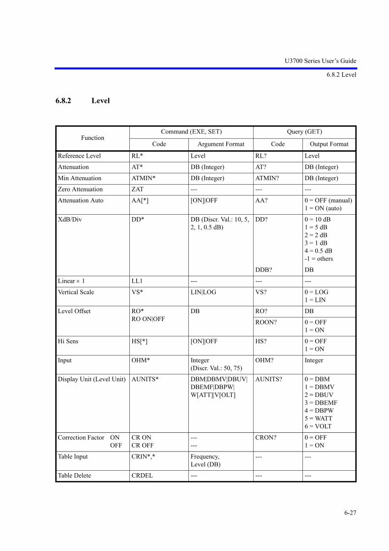
U3700 Series User’s Guide
6.8.2 Level
6-27
6.8.2 Level
FunctionCommand (EXE, SET) Query (GET)
Code Argument Format Code Output Format
Reference Level RL* Level RL? Level
Attenuation AT* DB (Integer) AT? DB (Integer)
Min Attenuation ATMIN* DB (Integer) ATMIN? DB (Integer)
Zero Attenuation ZAT --- --- ---
Attenuation Auto AA[*] [ON]|OFF AA? 0 = OFF (manual) 1 = ON (auto)
XdB/Div DD* DB (Discr. Val.: 10, 5, 2, 1, 0.5 dB)
DD? 0 = 10 dB 1 = 5 dB 2 = 2 dB 3 = 1 dB 4 = 0.5 dB -1 = others
DDB? DB
Linear 1 LL1 --- --- ---
Vertical Scale VS* LIN|LOG VS? 0 = LOG 1 = LIN
Level Offset RO* RO ON|OFF
DB RO? DB
ROON? 0 = OFF 1 = ON
Hi Sens HS[*] [ON]|OFF HS? 0 = OFF 1 = ON
Input OHM* Integer (Discr. Val.: 50, 75)
OHM? Integer
Display Unit (Level Unit) AUNITS* DBM|DBMV|DBUV|DBEMF|DBPW| W[ATT]|V[OLT]
AUNITS? 0 = DBM 1 = DBMV 2 = DBUV 3 = DBEMF 4 = DBPW 5 = WATT 6 = VOLT
Correction Factor ON OFF
CR ON CR OFF
--- ---
CRON? 0 = OFF 1 = ON
Table Input CRIN*,* Frequency, Level (DB)
--- ---
Table Delete CRDEL --- --- ---

U3700 Series User’s Guide
6.8.3 Bandwidth
6-28
6.8.3 Bandwidth
FunctionCommand (EXE, SET) Query (GET)
Code Argument Format Code Output Format
RBW RB* Frequency RB? Frequency
RBW Auto BA[*] [ON]|OFF BA? 0 = OFF 1 = ON
VBW VB* Frequency VB? Frequency
VBW Auto VA[*] [ON]|OFF VA? 0 = OFF (manual) 1 = ON (auto)
Couple All Auto AL[*] [ON]|OFF AL? 0 = OFF 1 = ON (all auto)
RBW : Span CORS* CORS ON[*] CORS OFF
Ratio (float) CORS? Ratio (float)
CORSON? 0 = OFF 1 = ON
VBW : RBW COVR* COVR ON[*] COVR OFF
Ratio (float) COVR? Ratio (float)
COVRON? 0 = OFF 1 = ON
PLL Band Width PLLBW* AUTO|MID|NARW PLLBW* 0 = Auto 1 = Narrow 2 = Medium

U3700 Series User’s Guide
6.8.4 Sweep
6-29
6.8.4 Sweep
6.8.5 Trigger
FunctionCommand (EXE, SET) Query (GET)
Code Argument Format Code Output Format
Sweep Time SW|ST* Time SW?|ST? Time
Sweep Auto AS[*] [ON]|OFF AS? 0 = OFF (manual) 1 = ON (auto)
Sweep Mode --- --- SWM? 0 = Single 1 = Normal
Sweep Mode Normal SN|CONTS --- --- ---
Sweep Mode Single SI|SNGLS --- --- ---
Take Sweep TS --- --- ---
Sweep Start / Stop SR --- --- ---
Gated Sweep Mode GTSWP* ON|OFF GTSWP? 0 = OFF 1 = ON
Gate Source GTSRC* EXT|IF GTSRC? 2 = EXT 3 = IF
Gate Slope GTSLP* (FALL|NEG|-)|(RISE|POS|+)
GTSLP? 0= RISE|POS|+ 1= FALL|NEG|-
Gate Delay GTPOS Time GTPOS? Time
Gate Width GTWID* Time GTWID? Time
FunctionCommand (EXE, SET) Query (GET)
Code Argument Format Code Output Format
Trigger Mode TRGSRC* FREE|IF|EXT|VIDEO TRGSRC? 0 = FREE 1 = TRG_VIDEO 2 = TRG_EXT 3 = TRG_IF
Video or IF Trigger Level TRGLVL* Level TRGLVL? Level
External Trigger Level TRGTTLLVL* Voltage TRGTTLLVL? Voltage
Trigger Slope TRGSLP* (FALL|NEG|-)|(RISE|POS|+)
TRGSLP? 0 = RISE|POS| +1 = FALL|NEG|-
Trigger Delay TRGDLY* Time TRGDLY? Time

U3700 Series User’s Guide
6.8.6 Trace
6-30
6.8.6 Trace
NOTE: Three Traces are available A, B and C. In the Command List below, just replace <n> by the letter for theselected trace ie<n> = A | B | C
FunctionCommand (EXE, SET) Query (GET)
Code Argument Format Code Output Format
Trace Mode --- --- T<n>? 0 = WRITE 1 = VIEW 2 = BLANK
Write <n>W --- --- ---
View <n>V --- --- ---
Blank <n>B --- --- ---
Calc Mode Trace A CALCA* WRITE|MIN|MAX|AVG|PAVG|MAXCONT
CALCA? 0 = WRITE 1 = MIN HOLD 2 = MAX HOLD 3 = AVERAGE 4 = POWER AVG5 = MAX HOLD
CONT
Calc Mode Trace B CALCB* WRITE|MIN|MAX|AVG|PAVG|MAXCONT
CALCB? 0 = WRITE 1 = MIN HOLD 2 = MAX HOLD 3 = AVERAGE 4 = POWER AVG5 = MAX HOLD CONT
Calc Mode Trace C CALCC* WRITE|MIN|MAX|AVG|PAVG|MAXCONT
CALCC? 0 = WRITE 1 = MIN HOLD 2 = MAX HOLD 3 = AVERAGE 4 = POWER AVG5 = MAX HOLD CONT
Calc Mode : Max Hold <n>MAX* ON|OFF <n>MAX? 0 = OFF 1 = ON
Calc Mode : Min Hold <n>MIN* ON|OFF <n>MIN? 0 = OFF 1 = ON
Averaging and Power Averaging Times
<n>G* Integer <n>G? Integer

U3700 Series User’s Guide
6.8.6 Trace
6-31
Averaging and Power Averaging Times Active Trace
SWPCNT* Integer SWPCNT? Integer
Average Start <n>AVG*|<n>GR ON <n>AVG? 0 = OFF 1 = ONAverage Stop <n>AVG*|<n>GS OFF
Average : Pause <n>GP --- <n>GP? 0 = Continue 1 = PauseAverage : Continue <n>GC ---
Average : 1 Time <n>GSGL --- <n>GSGL? 0 = sliding 1 = onceAverage : Continuous <n>GCNT ---
Power Average Start <n>PAVG* ON <n>PAVG? 0 = OFF 1 = ONPower Average Stop <n>PAVG* OFF
Power Average : Pause <n>PGP --- <n>PGP? 0 = Continue 1 = PausePower Average : Continue <n>PGC ---
Power Average : 1 Time <n>PGSGL --- <n>PGSGL? 0 = sliding 1 = oncePower Average :
Continuous<n>PGCNT ---
Math : A-BA ABA --- --- ---
Math : B-AA BAA --- --- ---
Math : A-DLA ADLA --- --- ---
Math : B-AB BAB --- --- ---
Math : A-BB ABB --- --- ---
Math : B-DLB BDLB --- --- ---
Math : A-BC ABC --- --- ---
Math : B-AC BAC --- --- ---
Math : Trace Subtraction TRSUB* OFF|ABA|BAA|ADLA|BAB|ABB|BDLB|ABC|BAC
TRSUB? 0 = OFF 1 = ABA 2 = BAA 3 = ADLA 4 = BAB 5 = ABB 6 = BDLB 7 = ABC 8 = BAC
Math : Trace Store(Current trace trace n)
STORE* TRA|TRB|TRC --- ---
Number of Trace Points TPS|TP* 501 TP? 0 = 501 1 = 1001TPL|TP* 1001
FunctionCommand (EXE, SET) Query (GET)
Code Argument Format Code Output Format

U3700 Series User’s Guide
6.8.6 Trace
6-32
Detector Mode Trace A DET* NRM|POS|NEG|SMP|AVG|QP
DET? 0 = NRM 1 = POS 2 = NEG 3 = SMP 4 = AVG 5 = QP
Detector Mode Trace B DETB* NRM|POS|NEG|SMP|AVG|QP
DETB? 0 = NRM 1 = POS 2 = NEG 3 = SMP 4 = AVG 5 = QP
Detector Mode Trace C DETC* NRM|POS|NEG|SMP|AVG|QP
DETC? 0 = NRM 1 = POS 2 = NEG 3 = SMP 4 = AVG 5 = QP
Detector Mode Auto DETA<n>* ON|OFF DETA<n>? 0 = OFF 1 = ON
Detector Average Mode DETAVG* RMS|VIDEO DETAVG? 0 = VIDEO 1 = RMS
Select Active Trace TRACESEL* TRA|TRB|TRC TRACESEL? 0 = TRA 1 = TRB 2 = TRC
Trace A I/O ASCII TAA DDDDD<DLM>TRP (*1)
TAA? DDDDD<DLM>TRP (*1)
Trace A I/O Binary TBA 2Bytes*TRP TBA? 2BytesTRP
Trace B I/O ASCII TAB DDDDD<DLM>TRP (*1)
TAB? DDDDD<DLM>TRP (*1)
Trace B I/O Binary TBB 2BytesTRP TBB? 2BytesTRP
Trace C I/O ASCII TAC DDDDD<DLM>TRP (*1)
TAC? DDDDD<DLM>TRP (*1)
Trace C I/O Binary TBC 2BytesTRP TBC? 2BytesTRP
Trace Output Fornat
16bits Integer FORM1 --- ---
16bits Integer FORM2 --- ---
IEEE 32bits Float FORM3 --- ---
IEEE 32bits Float FORM4 --- ---
FunctionCommand (EXE, SET) Query (GET)
Code Argument Format Code Output Format

U3700 Series User’s Guide
6.8.7 Pass/Fail
6-33
6.8.7 Pass/Fail
FunctionCommand (EXE, SET) Query (GET)
Code Argument Format Code Output Format
Pass/Fail Judgement PFC* ON|OFF PFC? 0 = OFF 1 = ON
Judgement Result --- --- PFJ?|OPF? 0 = Pass 4 = Error 1 = Fail Limit 1 2 = Fail Limit 2 3 = Fail Limit 1&2
X Position Mode LIMPOS* ABS|LFT|CENT LIMPOS? 0 = ABS 1 = CENT (center freq) 2 = LFT (start freq)
Y Position Mode LIMAPOS* ABS|REF|DL LIMAPOS? 0 = ABS 1 = REF 2 = DL
X Offset Activate LIMS* ON|OFF LIMS? 0 = OFF 1 = ON
X Offset Frequency Domain
LIMSF* Frequency LIMSF? Frequency
X Offset Time Domain LIMST* Time LIMST? Time
Y Offset Activate LIMAS* ON|OFF LIMAS? 0 = OFF 1 = ON
Y Offset LIMASFT* DB LIMASFT? DB
Limit Line 1 LMTA* ON|OFF LMTA? 0 = OFF 1 = ON
Limit Line 1 Frequency Domain Data Input
LMTAINF*,* Frequency, Level --- ---
Limit Line 1 Time Domain Data Input
LMTAINT*,* Time, Level --- ---
Limit Line 1 Frequency Domain Data Erase
LMTADELF --- --- ---
Limit Line 1 Time Domain Data Erase
LMTADELT --- --- ---
Limit Line 2 LMTB* ON|OFF LMTB? 0 = OFF 1 = ON
Limit Line 2 Frequency Domain Data Input
LMTBINF*,* Frequency, Level --- ---

U3700 Series User’s Guide
6.8.8 Display
6-34
6.8.8 Display
Limit Line 2 Time Domain Data Input
LMTBINT*,* Time, Level --- ---
Limit Line 2 Frequency Domain Data Erase
LMTBDELF --- --- ---
Limit Line 2 Time Domain Data Erase
LMTBDELT --- --- ---
Limit Line 1 Pass Range LARNG* ABOVE|BELOW LARNG? 0 = ABOVE 1 = BELOW
Limit Line 2 Pass Range LBRNG* ABOVE|BELOW LBRNG? 0 = ABOVE 1 = BELOW
FunctionCommand (EXE, SET) Query (GET)
Code Argument Format Code Output Format
Display Line Level DLN DLN ON[,*] DLN OFF
Level DLN? Level
DLNON? 0 = OFF 1 = ON
Reference Line Level RLN* RLN ON[,*] RLN OFF
Level RLN? Level
RLNON? 0 = OFF 1 = ON
Window Center Position WLX* Frequency|Time WLX? Frequency|Time
Window Width WDX* Frequency|Time WDX? Frequency|Time
Window Sweep WDOSWP* ON|OFF WDOSWP? 0 = OFF 1 = ON
Zoom MLTSCR* ZM|FT|TT|OFF MLTSCR? 0 = OFF 1 = ZM 2 = FT 3 = TT4 = DUAL
VIEWER
Zoom Position ZMPOS* Frequency|Time ZMPOS? Frequency|Time
Zoom Width ZMWID* Frequency|Time ZMWID? Frequency|Time
Frequency Pos FTPOS* Frequency FTPOS? Frequency
Select Active Context CTXTSEL* Integer (0|1) SCRSEL? 0 = CTXT A1 = CTXT B
FunctionCommand (EXE, SET) Query (GET)
Code Argument Format Code Output Format

U3700 Series User’s Guide
6.8.9 Marker
6-35
6.8.9 Marker
<n> = 0 | 1 | 2 | 3 | 4 | 5 | 6 | 7 | 8 | 9 | 10
NOTE: Marker 0 is the reference marker.
2 Channels Viewer DUALCH[*] [ON]|OFF DUALCH? 0 = OFF 1 = ON
2 Channel Preset DUALCHINIT --- --- ---
FunctionCommand (EXE, SET) Query (GET)
Code Argument Format Code Output Format
All Markers Off MO|MKOFF --- --- ---
All Markers Off Except Active Marker
MLTOFF --- --- ---
Select Active Marker MKRSEL* <n> MKRSEL? <n>
Active Marker ON / OFF MLN* ON|OFF MLN? 0 = OFF 1 = ON
Marker ON / OFF MLN<n>* [ON]|OFF MLN<n>? 0 = OFF 1 = ON
Active Marker Frequency MK* Frequency|Time MK? MF?
Frequency|Time
Marker Frequency MF<n>* Frequency|Time MF<n>? Frequency|Time
Active Marker Level --- --- ML? Level
Marker Level --- --- ML<n>? Level
Active Marker Freq + Lev --- --- MFL? Frequency|Time, Level
Marker Freq + Lev --- --- MFL<n>? Frequency|Time, Level
Active Marker Num + Stauts + Freq + Lev
--- --- MFLC? Marker Number, Status (1=ON|0=OFF), Frequency|Time, Level
FunctionCommand (EXE, SET) Query (GET)
Code Argument Format Code Output Format

U3700 Series User’s Guide
6.8.9 Marker
6-36
MarkerNum + Stauts + Freq + Lev
--- --- MFLC<n>? Marker Number, Status (1=ON|0=OFF), Frequency|Time, Level
Reference Marker Fre-quency Absolute Value
--- --- MDF2? MFR?
Frequency|Time
Reference Marker Level Absolute Value
--- --- MDL2? MLR?
Level
Delta Mode MKD* [ON]|OFF --- ---
Reference Object MKROBJ* MARK|RLIN MKROBJ? 0 = MARK 1 = RLIN
Fixed Marker FX* ON|OFF FX? 0 = OFF 1 = ON
Inverse Marker REDLT* ON|OFF REDLT? 0 = OFF 1 = ON
Delta Mode Reference MKROJB* MARK|RLIN|DLIN|LLINU|LLINL
MKROBJ? MARK|RLIN|DLIN|LLINU|LLINL
Marker Step Size MPM* Frequency|Time MPM? Frequency|Time
Marker Step Auto MPA[*] [ON]|OFF MPA? 0 = OFF 1 = ON
Signal Track SG[*] [ON]|OFF SG? 0 = OFF 1 = ON
Signal Track Y Range SGY[ON,]* SGY ON SGY OFF
Level SGY? Level
SGYON? 0 = OFF 1 = ON
Active Marker Trace MKTRACE* TRA|TRB|TRC MKTRACE? 0 = TRA 1 = TRB 2 = TRC
Marker Mode MKMODE* INDEX|VAL MKMODE? 0 = INDEX 1 = VAL
Display Marker List MKLST ON|OFF MKLST? 0 = OFF 1 = ON
Get Marker List --- --- MLSFL? Num Marker, Active (1=ON|0=OFF), Frequency|Time, Level (, )
FunctionCommand (EXE, SET) Query (GET)
Code Argument Format Code Output Format

U3700 Series User’s Guide
6.8.10 Peak and Marker Move
6-37
6.8.10 Peak and Marker Move
FunctionCommand (EXE, SET) Query (GET)
Code Argument Format Code Output Format
MKR CF MC|MKCF --- --- ---
MKR CF MTCF --- --- ---
MKR REF MR|MKRL --- --- ---
PEAK CF PKCF --- --- ---
PEAK REF PKRL --- --- ---
MKR SPAN DS|MTSP --- --- ---
MKR CF Step M0|MKCS --- --- ---
MKR CF Step M1|MTCS --- --- ---
MKR MKR Step M2|MKMKS --- --- ---
MKR MKR Step M3|MTMKS --- --- ---

U3700 Series User’s Guide
6.8.11 Peak
6-38
6.8.11 Peak
FunctionCommand (EXE, SET) Query (GET)
Code Argument Format Code Output Format
Peak Search PS --- --- ---
Next Peak NXP --- --- ---
Next Peak Left NXL --- --- ---
Next Peak Right NXR --- --- ---
Min Search MIS --- --- ---
Next Min Peak NXM --- --- ---
Min Max Peak MMS --- --- ---
Continuous Peak CP* ON|OFF CP? 0 = OFF 1 = ON
Peak Y Div DY* Level Div DY? Level Div
Peak List Frequency Level
PLS FREQ PLS LEVEL
--- --- ---
X Peak Area Couple to Window
MKSX OFF|IN|OUT MKSX? 0 = OFF 1 = IN 2 = OUT
X Peak Area Position MKSPOS* Frequency|Time MKSPOS? Frequency|Time
X Peak Area Width MKSWID* Frequency|Time MKSWID? Frequency|Time
Y Peak Area Couple to Display Line
MKSYDL OFF|ABOVE|BELOW
MKSYDL? 2 = OFF 0 = ABOVE 1 = BELOW
Y Peak Area Couple to Limit Line 1
MKSYLA OFF|ABOVE|BELOW
MKSYLA? 2 = OFF 0 = ABOVE 1 = BELOW
Y Peak Area Couple to Limit Line 2
MKSYLB OFF|ABOVE|BELOW
MKSYLB? 2 = OFF 0 = ABOVE 1 = BELOW

U3700 Series User’s Guide
6.8.12 Measurement
6-39
6.8.12 Measurement
FunctionCommand (EXE, SET) Query (GET)
Code Argument Format Code Output Format
Noise NI* Frequency NI? Frequency
Noise ON + dBm/Hz NIM --- --- ---
Noise ON + dBV/Hz NIU --- --- ---
Noise ON + dBc/Hz NIC --- --- ---
Noise OFF NIF --- --- ---
Noise Mode Query --- --- NION? 0 = OFF 1 = dBm/Hz 2 = dBV/Hz 3 = dBc/Hz
Noise Value --- --- NIRES? Level
X dB Down Level MKBW* DB MKBW? DB
X dB Down XDB --- --- ---
X dB Down Left XDL --- --- ---
X dB Down Right XDR --- --- ---
X dB Relative X dB Absolute Left X dB Absolute Right
DC0 DC1 DC2
---------
DC? 0 = Relative 1 = Absolute Left 2 = Absolute Right
Continuous dB Down CDB[*] [ON]|OFF CDB? 0 = OFF 1 = ON
Peak + X dB Down PSXDB --- --- ---
IM Measurement Mode IMM[*] [ON]|OFF IMM? 0 = OFF 1 = ON
IM Reference Frequency --- --- IMMREF? Frequency, Level
IM Delta Frequency --- --- IMMDF? Delta Frequency
IM Distortion Signal Data Readout
--- --- IMMRES? n<DLM>LL1, LJ1, UL1, UJ1<DLM>(*1)
IM Order Setting IMODR* Integer (3|5|7|9) IMODR? Integer (3|5|7|9)
IM Criteria Input 3rd Order
IMLS3* DB IMLS3? DB
IM Criteria Input 5th Order
IMLS5* DB IMLS5? DB

U3700 Series User’s Guide
6.8.12 Measurement
6-40
IM Criteria Input 7th Order
IMLS7* DB IMLS7? DB
IM Criteria Input 9th Order
IMLS9* DB IMLS9? DB
IM Pass/Fail Judgement IMPFC* ON|OFF IMPFC? 0 = OFF 1 = ON
IM Save Setup IMSAVE --- --- ---
IM Restore Setup IMLOAD --- --- ---
Harmonics Measurement HARM[*] [ON]|OFF HARMON? 0 = OFF 1 = ON
Harmonics Results --- --- HARM? n<DLM>Freq1, Level1, DeltaLevel1<DLM>(*2)
Harmonics Max Order HARMNUM* Integer HARMNUM? Integer
Harmonics Fundamental HRMFND [ON,] *HRMFND ON HRMFND OFF
Frequency HRMFND? Frequency
HRMFND ON? 0 = OFF 1 = ON
(*1)n: Result set number corresponding to the orderLLn: Level difference in the lower frequency signalLJn: Pass/Fail judgment in the lower frequency signal0: Pass1: Fail-1: Judgment offULn: Level difference in the upper frequency signalUJn: Pass/Fail judgment in the upper frequency signal<DLM>: Delimiter
(*2)n: Result set number.Freqn: Harmonic frequency.Leveln: Harmonic level.DeltaLeveln: Harmonic level difference with fundamental frequency.<DLM>: Delimiter
FunctionCommand (EXE, SET) Query (GET)
Code Argument Format Code Output Format

U3700 Series User’s Guide
6.8.12 Measurement
6-41
FunctionCommand (EXE, SET) Query (GET)
Code Argument Format Code Output Format
AM Modulation Measure-ment
AMMOD* ON|OFF AMMODON? 0=OFF 1=ON
AM Modulation Depth --- --- AMMOD? Real %
AM Modulation --- --- AMMF? Frequency
FM Measurement FMMEAS* ON|OFF FMMEASON? 0=OFF 1=ON
FM Frequency Deviation --- --- FMMEAS? Frequency
Modulation Frequency to Sweep time
FMMODF[ON,]* (*3)
Frequency FMMODF? Frequency
FMMODFY* (*4) Frequency FMMODFY? Frequency
FMMODF* ON|OFF FMMODFON? 0=OFF 1=ON
Sound Mode
:ON SON --- SD? 0 = OFF 1 = ON (AM) 2 = ON (FM)
:ON (AM) SAM
:ON (FM) SFM
:OFF SOF
Sound Volume SDV* Integer SDV? Integer
Demodulation Time PU* Time PU? Time
(*3) Sets the Modulation Frequency to Sweep Time mode to ON and then sets an FM frequency devia-tion value.
(*4) Sets an FM frequency deviation value without setting the Modulation Frequency to Sweep Time mode to ON.

U3700 Series User’s Guide
6.8.13 Counter
6-42
6.8.13 Counter
FunctionCommand (EXE, SET) Query (GET)
Code Argument Format Code Output Format
Resolution 1 kHz CN0 --- --- ---
Resolution 100 Hz CN1 --- --- ---
Resolution 10 Hz CN2 --- --- ---
Resolution 1 Hz CN3 --- --- ---
Resolution Query --- --- CN? 0 = 1 kHz 1 = 100 Hz 2 = 10 Hz 3 = 1 Hz
Counter Position CNPOS* Frequency CNPOS? Frequency
Counter Position Auto(Position Linked to Marker)
CNPOSA[*] [ON]|OFF CNPOSA? 0 = OFF 1 = ON
Counter COUNT* ON|OFF COUNT? 0 = OFF 1 = ON
Counter Value --- --- CNRES? Frequency

U3700 Series User’s Guide
6.8.14 Power
6-43
6.8.14 Power
FunctionCommand (EXE, SET) Query (GET)
Code Argument Format Code Output Format
Measure Mode PMEASMODE? 0 = OFF 1 = CHPOW 2 = TOTPOW 3 = AVGPOW 4 = OBW 5 = ACP 6 = SEM 7 = SPU
Measure OFF PMEASOFF --- --- ---
Measure Averaging PMEASAVG* ON|OFF PMEASAVG? 0 = OFF 1 = ON
PMEASAVGONCE*
ONCE|MULT PMEASAVGONCE?
0 = ONCE 1 = MULT
Measure Averaging Times --- --- PMEASTM? Integer
Measure Trace PMEASTRACE* TRA|TRB|TRC PMEASTRACE?
0 = TRA 1 = TRB 2 = TRC
Channel Power ON/OFF PWCHON[*] [ON]|OFF PWCHON? 0 = OFF 1 = ON
Channel Power Average Times
PWCHTM* Integer PWCHTM? Integer
Channel Power --- --- PWCH? Level
Channel Power Spectral Density
--- --- PWCHPSD? dB
Power Measure Save PWCHSAVE --- --- ---
Power Measure Restore PWCHLOAD --- --- ---
Total Power ON/OFF PWTOTALON[*] [ON]|OFF PWTOTALON? 0 = OFF 1 = ON
Total Power Average Times
PWTOTALTM* Integer PWTOTALTM? Integer
Total Power --- --- PWTOTAL? Level
Total Power Spectral Den-sity
--- --- PWTOTALPSD?
dB
Power Measure Save PWTOTSAVE --- --- ---
Power Measure Restore PWTOTLOAD --- --- ---

U3700 Series User’s Guide
6.8.14 Power
6-44
Average Power ON/OFF PWAVGON[*] [ON]|OFF PWAVGON? 0 = OFF 1 = ON
Average Power Average Times
PWAVGTM* Integer PWAVGTM? Integer
Average Power Range PWAVGRANGE* FULL|WIN PWAVGRANGE?
0 = FULL 1 = WIN
Average Power --- --- PWAVG? Level
Power Measure Save PWAVGSAVE --- --- ---
Power Measure Restore PWAVGLOAD --- --- ---
OBW Execution OBWON[*] [ON]|OFF OBWON? 0 = OFF 1 = ON
OBW Measurement Value --- --- OBW? Frequency (Fc), Frequency (OBW)
OBW % OBWPER* Real% OBWPER? Real%
OBW Average Times OBWTM* Integer OBWTM? Integer
OBW save setup OBWSAVE --- --- ---
OBW restore setup OBWLOAD --- --- ---
ACP Execution ACP[*] [ON]|OFF ACPON? 0 = OFF 1 = ON
ACP Measurement Value --- --- ACP? n<DLM>f1L, l1L, f1H, l1H<DLM>(*1)
ACP Average Times ACPTM* Integer ACPTM? Integer
ACP Reference Power Value
--- --- ACPREF? Level
ACP Screen ACPSCR* FULL|CARR ACPSCR? 0 = FULL 1 = CARR
ACP Carrier Bandwidth CARRBS* ACPCBW*
Frequency CARRBS? ACPCBW
Frequency
CS/BS Table Input CSBSIN*,* Frequency (CS), Frequency (BS)
--- ---
CS/BS Table Deletion CSBSDEL --- --- ---
ACP Graphics Mode ADG[*] [ON]|OFF ADG? 0 = OFF 1 = ON
ACP save setup ACPSAVE --- --- ---
ACP restore setup ACPLOAD --- --- ---
ACP Nyquist Filter ACPNQST* ON|OFF ACPNQST? 0 = OFF 1 = ON
FunctionCommand (EXE, SET) Query (GET)
Code Argument Format Code Output Format

U3700 Series User’s Guide
6.8.14 Power
6-45
Nyquist Symbol Rate SYMRT* Frequency SYMRT? Frequency
Nyquist Roll Off Factor RFACT* Real RFACT? Real
Spectrum Emission Mask Execution
SEMON[*] [ON]|OFF SEMON? 0 = OFF 1 = ON
SEM Average Times SEMTM* Integer SEMTM? Integer
SEM Carrier Bandwidth SEMCBW* Frequency SEMCBW? Frequency
SEM Ref Power SEMRFCALC* CHN|PEAK SEMRFCALC? 0 = Channel 1 = Peak
SEM Nyquist Filter SEMNQST* ON|OFF SEMNQST? 0 = OFF 1 = ON
SEM save setup SEMSAVE --- --- ---
SEM restore setup SEMLOAD --- --- ---
SEM Band Table Input SEMTIN*,*,*,*,*,*,*,*
Frequency, (start) Frequency, (stop) Frequency, (ibw) dB, (limit abs start) dB, (limit abs stop) dB, (limit rel start) dB, (limit rel stop) ABS|REL|A_AND_R|A_OR_R (judge)
--- ---
SEM Band Table Delete SEMTDEL --- --- ---
SEM Reference Power --- --- SEMRFPOW? dBm
SEM Measurement Value --- --- SEM? Channel Number, Start Frequency, Stop Frequency, Frequency, Absolute Power, Relative Power, Judge (, )
Spurious Measurement Execution
SPURI* [ON|FREQ]|OFF SPURION? 0 = OFF 1 = ON
FunctionCommand (EXE, SET) Query (GET)
Code Argument Format Code Output Format

U3700 Series User’s Guide
6.8.14 Power
6-46
SPU Measurement Result --- --- SPURI? n<DLM>m1<DLM>f1, l1, j1<DLM> fm1, lm1, jm1<DLM>m2<DLM>f1, l1, j1<DLM> fm2, lm2, jm2<DLM>mn<DLM>f1, l1, j1<DLM> fmn, lmn, jmn<DLM>(*2)
SPU Table Selection SPRTBL* Integer (0|1|2) SPRTBL? Integer (0|1|2)
SPU Table Input Freq SPRIN|SPRFIN *,*,*,*,*
Freq, (start) Freq, (stop) AUTO|Freq, (rbw) AUTO|Freq, (vbw) AUTO|Time, (swp) Level, (ref level) AUTO|Level, (att) ON|OFF, (preamp) Level (Limit)
--- ---
SPU Freq Table Deletion SPRFDEL --- --- ---
(*1)n: Number of points (0 thru 5)fnL: nth frequency LowlnL: nth level LowfnH: nth frequency HighlnH: nth level High<DLM>: Delimiter
(*2)n: Number of measurement points (0 thru 15)m: Number of spurious signal (0 thru 10)f: Spurious frequencyl: Spurious levelj: Spurious judgment result (0:Pass, 1:Fail)<DLM>: Delimiter
FunctionCommand (EXE, SET) Query (GET)
Code Argument Format Code Output Format

U3700 Series User’s Guide
6.8.15 EMC
6-47
6.8.15 EMC
6.8.16 Calibration
FunctionCommand (EXE, SET) Query (GET)
Code Argument Format Code Output Format
Correction Factor CR[*] [ON]|OFF CRON? 0 = OFF 1 = ON
Correction Factor Table Input
CRIN*,* Frequency, Level(DB) --- ---
Correction Factor Table Deletion
CRDEL --- --- ---
EMC Trace DetectionOFFON
EMCON|EMCDETNRM|OFFPEAK|ON
EMCON?EMCDET?
0 = OFF3 = ON
EMC BWAuto200 Hz9 kHz120 kHz1 MHz
QPAUTO|QAQP0QP1QP2QP3
---QPAUTO?QA?
0 = Auto 1 = 200 Hz 2 = 9 kHz 3 = 120 kHz 4 = 1 MHz
FunctionCommand (EXE, SET) Query (GET)
Code Argument Format Code Output Format
Calibration All CLALL --- --- ---
Total Gain Calibration CLGAIN[*] [RFC1]|RFC2 CLGAIN [RFC1]|RFC2?
Integer 0 = OK>0 = Warning<0 = Error
RBW Calibration CLRBW --- CLRBW? Integer 0 = OK>0 = Warning<0 = Error
PBW Calibration CLPBW --- CLPBW? Integer 0 = OK>0 = Warning<0 = Error

U3700 Series User’s Guide
6.8.17 Save/Recall
6-48
6.8.17 Save/Recall
ATT step Calibration CLATT --- CLATT? Integer 0 = OK>0 = Warning <0 = Error
CAL 10 M Reference Coarse
CLCREF* Integer CLCREF? Integer
CAL 10 M Reference Fine CLFREF* Integer CLFREF? Integer
CAL 10 M Reference Default
CLDREF --- --- ---
CAL 10 M Reference Store
CLSREF --- --- ---
F-Correction FC* ON|OFF FC? 0 = OFF 1 = ON
CAL-Correction CC* ON|OFF CC? 0 = OFF 1 = ON
FunctionCommand (EXE, SET) Query (GET)
Code Argument Format Code Output Format
Save (File or File Number)
SV[*] :String|Integer --- ---
Delete (File) DEL* :String --- ---
Recall (File) RC* :String --- ---
Rename (File, New Name)
RENAME*,* :String, :String --- ---
Write Protect (File) WP*,* :String, ON|OFF --- ---
File Format FILEFORMAT* BIN|XML FILEFORMAT? 0 = BIN 1 = XML
Media FILEMEDIA* FLASH|USB FILEMEDIA? 0 = FLASH 1 = USB
Save Setup SVSET* ON|OFF SVSET? 0 = OFF 1 = ON
Save Trace A Context 1 SVTRC1A* ON|OFF SVTRC1A? 0 = OFF 1 = ON
FunctionCommand (EXE, SET) Query (GET)
Code Argument Format Code Output Format

U3700 Series User’s Guide
6.8.17 Save/Recall
6-49
Save Trace B Context 1 SVTRC1B* ON|OFF SVTRC1B? 0 = OFF 1 = ON
Save Trace C Context 1 SVTRC1C* ON|OFF SVTRC1C? 0 = OFF 1 = ON
Save Trace A Context 2 SVTRC2A* ON|OFF SVTRC2A? 0 = OFF 1 = ON
Save Trace B Context 2 SVTRC2B* ON|OFF SVTRC2B? 0 = OFF 1 = ON
Save Limit Line 1 SVLIM1* ON|OFF SVLIM1? 0 = OFF 1 = ON
Save Limit Line 2 SVLIM2* ON|OFF SVLIM2? 0 = OFF 1 = ON
Save Spurious Table 1 SVSPR1* ON|OFF SVSPR1? 0 = OFF 1 = ON
Save Spurious Table 2 SVSPR2* ON|OFF SVSPR2? 0 = OFF 1 = ON
Save Spurious Table 3 SVSPR3* ON|OFF SVSPR3? 0 = OFF 1 = ON
Save Channel SVCH* ON|OFF SVCH? 0 = OFF 1 = ON
Save Spectrum Emission Mask Table
SVSEM* ON|OFF SVSEM? 0 = OFF 1 = ON
Save ACP SVACP* ON|OFF SVACP? 0 = OFF 1 = ON
Save Correction Factor SVANT* ON|OFF SVANT? 0 = OFF 1 = ON
Save NormalizeContext A Trace A
SVNRM1A ON|OFF SVNRM1A? 0 = OFF 1 = ON
Save NormalizeContext A Trace B
SVNRM1B ON|OFF SVNRM1B? 0 = OFF 1 = ON
Save NormalizeContext A Trace C
SVNRM1C ON|OFF SVNRM1C? 0 = OFF 1 = ON
Syncronize All Files: USB to Flash: Flash to USB
SYNCTOFLASH USB
--- ---
FunctionCommand (EXE, SET) Query (GET)
Code Argument Format Code Output Format
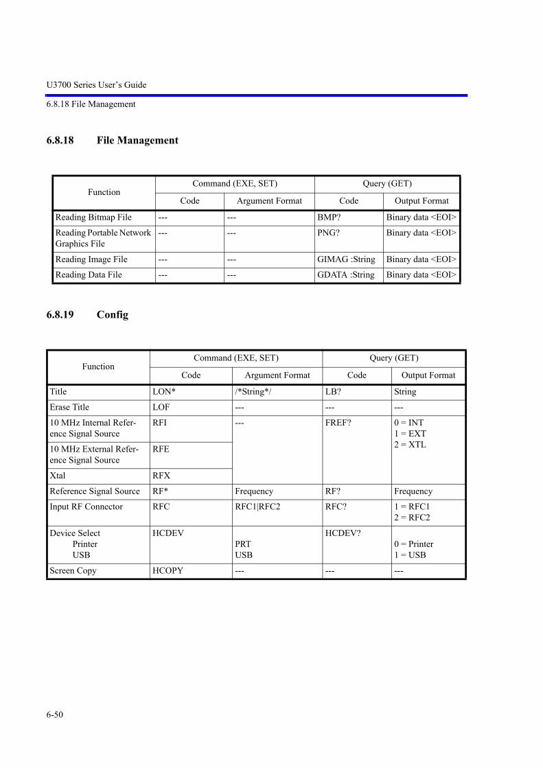
U3700 Series User’s Guide
6.8.18 File Management
6-50
6.8.18 File Management
6.8.19 Config
FunctionCommand (EXE, SET) Query (GET)
Code Argument Format Code Output Format
Reading Bitmap File --- --- BMP? Binary data <EOI>
Reading Portable Network Graphics File
--- --- PNG? Binary data <EOI>
Reading Image File --- --- GIMAG :String Binary data <EOI>
Reading Data File --- --- GDATA :String Binary data <EOI>
FunctionCommand (EXE, SET) Query (GET)
Code Argument Format Code Output Format
Title LON* /*String*/ LB? String
Erase Title LOF --- --- ---
10 MHz Internal Refer-ence Signal Source
RFI --- FREF? 0 = INT 1 = EXT 2 = XTL10 MHz External Refer-
ence Signal SourceRFE
Xtal RFX
Reference Signal Source RF* Frequency RF? Frequency
Input RF Connector RFC RFC1|RFC2 RFC? 1 = RFC1 2 = RFC2
Device SelectPrinterUSB
HCDEVPRT USB
HCDEV?0 = Printer 1 = USB
Screen Copy HCOPY --- --- ---

U3700 Series User’s Guide
6.8.20 Preset
6-51
6.8.20 Preset
6.8.21 GPIB
FunctionCommand (EXE, SET) Query (GET)
Code Argument Format Code Output FormatPreset IP|*RST --- --- ---Factory Init SUPIP --- --- ---
FunctionCommand (EXE, SET) Query (GET)
Code Argument Format Code Output FormatStatus Byte Clear *CLS --- --- ---STB Read --- --- *STB? IntegerSRE Read/Write *SRE0* Integer *SRE? IntegerESR Read --- --- *ESR? IntegerESE Read/Write *ESE Integer *ESE? IntegerOSR Read --- --- OPREVT? IntegerOSER Read OPR* Integer OPR? IntegerSRQ Interrupt ON S0 --- --- ---SRQ Interrupt OFF S1 --- --- ---SRQ status clear S2 --- --- ---Delimiter CR LF EOI DLIM0 --- --- ---Delimiter LF DLIM1Delimiter EOI DLIM2 --- --- ---Delimiter ; DLIM5Local Lockout LLO --- --- ---Remote Control REN --- --- ---Local Control GTL --- --- ---R3162 Mode INSTR* FUS|SA2 INSTR? 0 = FUS
1 = SA2Refresh Screen in Remote Control
SCRF[*] [ON]|OFF SCRF? ON|OFF
Open Menus in Remote Control
MNRF[*] [ON]|OFF MNRF? ON|OFF
Annotations ANNOT[*] [ON]|OFF ANNOT? ON|OFFParser Mode PARSER* ATSET|SCPISET PARSER? 0 = AT
1 = SCPI(*1) TRP: Number of trace points
<DLM>: Delimiter

U3700 Series User’s Guide
6.8.22 Others
6-52
6.8.22 Others
FunctionCommand (EXE, SET) Query (GET)
Code Argument Format Code Output Format
Device ID Output --- --- *IDN?ID?
Maker Name, Device Name, Serial No., Revision
Date Setting SETDATE* Date (YYMMDD) SETDATE? Date
Time Setting SETTIME* Time (HHMMSS) SETTIME? Time
Reset user password (for front panel lock)
RPWD --- --- ---
Option List --- --- *OPT? Opt1,Opt2,...,Optn<DLM>
Option
: 2CH Input --- --- OPT10? 1 = Installed 0 = Not installed: 2CH Input 75 Ohm --- --- OPT11?
:75 Ohm Input --- --- OPT15?
: High Stability --- --- OPT20?
: EMC Filter --- --- OPT28?
: 3GPP Demod --- --- OPT50?
: Time Domain --- --- OPT53?
: Time Domain 2CH --- --- OPT54?
: TG -30 dBm --- --- OPT74?
: TG -60 dBm 75 Ohm --- --- OPT75?
: TG -60 dBm --- --- OPT76?
: TG High Freq. --- --- OPT77?
Execute Self Test --- --- *TST? Supply_Voltage, judge<DLM> (*1)Memory, judge<DLM>CPU_Registers, judge<DLM>RF_Registers, judge<DLM>RF_PLL_Lock, judge<DLM>LO_Registers, judge<DLM>LO_PLL_Lock, judge<DLM>AIF_Registers, judge<DLM>AIF_PLL_Lock, judge<DLM>TG_Registers, judge<DLM> (*2)Temperature, judge<DLM> (*1)
(*1) CH1 @ 2ch option(*2) CH1 @2ch option & TG Option

U3700 Series User’s Guide
6.8.23 TG
6-53
6.8.23 TG
FunctionCommand (EXE, SET) Query (GET)
Code Argument Format Code Output FormatTG ON TG --- TG? 0 = OFF
1 = ONTG OFF TGF --- --- ---TG Level TGL* Level TGL? LevelTG Frequency Offset TGO[ON,]*
TGO ON|OFFFrequency TGO?
TGOON?Frequency 0 = OFF 1 = ON
TG Level Offset TGLO[ON,]* TGLO ON|OFF
DB TGLO? TGLOON?
DB 0 = OFF 1 = ON
Capture Normalize Data Active Trace
CAPND --- --- ---
Normalize Correction Active Trace
NORM* ON|OFF NORM? 0 = OFF 1 = ON
Capture Normalize Data Trace (n = A|B|C)
<n>RX --- --- ---
Normalize Correction Trace (n = A|B|C)
<n>NORM* ON|OFF <n>NORM? 0 = OFF 1 = ON
Normalize Execute Active Trace
AR --- --- ---
Delta Reference Line TGDLTRLN* ON|OFF TGDLTRLN? 0 = OFF 1 = ON
VSWR ON/OFF VSWRON [*] [ON]|OFF VSWRON? 0 = OFF 1 = ON
VSWR Measurement Value
--- --- VSWR? Real
VSWR Return Loss Value --- --- VSWRLOSS? DB (Real)

U3700 Series User’s Guide
6.8.24 Units
6-54
6.8.24 Units
Function Code
Exponent E (see IEEE Std 488.2-1992 page 89)
GHz GZ
MHz MZ
KHz KZ
Hz HZ
DB DB
DBM DBM
DBMV DBMV
DBUV DBUV
DBEMF DBEMF
DBPW DBPW
Watt W | WATT
mW MW
Volt V | VOLT
Millivolt MV
Microvolt UV
Nanovolt NV
Second SC
Millisecond MS | MSEC
Microsecond US | USEC
Nanosecond NSEC
% % | PER
ppm PPM

U3700 Series User’s Guide
6.9 Example of Remote Control Programs
6-55
6.9 Example of Remote Control Programs
This chapter describes examples of programs which control the instrument by remote.
The example programs in this chapter use the Microsoft Corp. Visual Basic language. If programming inanother language, the example programs must be described in that language.
The explanation of the programs here assumes that the GPIB board provided by the National InstrumentsCorp. (hereafter referred to as the NI Corp.) is used as a GPIB controller.
6.9.1 Basic Steps for GPIB Bus Control
This section describes the step-by-step procedures in which the GPIB bus is controlled by the Visual Basicprograms. For operations such as initializing variables and defining function routines, which depend onVisual Basic, the notational rules for the Visual Basic program must be applied.
6.9.1.1 Reading the GPIB Control Library for Visual Basic
To control the GPIB board provided by NI Corp. by using the program described in the Visual Basic lan-guage, the two files must be built into the Visual Basic Project. Those two files are the VBIB-32.BAS file,in which the GPIB communication interface for the Visual Basic language provided by the NI Corp. isdescribed, and the NIGLOBAL.BAS file, in which errors and timeout values are defined.
6.9.1.2 Program Examples Using VB
Example 1 Setting the center frequency after resetting this instrument.
Call ibdev(0,8,T10S,1,0,SPA) ’ InitializeCall ibclr(spa) ’ Performs a Device Clear.
Call ibwrt(spa, "IP") ’ presetCall ibwrt(spa, "CF 30MZ") ’ Sets the center frequency to 30 MHz.
Example 2 Setting the start frequency to 300 kHz, setting the stop frequency to 800 kHz and adding 50kHz to the frequency offset.
Call ibclr(spa) ’ Performs a Device Clear.Call ibwrt(spa, "FA 300KZ") ’ Sets the start frequency to 300 kHz.Call ibwrt(spa, "FB 800KZ") ’ Sets the stop frequency to 800 kHz.Call ibwrt(spa, "FO 50KZ") ’ Adds 50 kHz to the frequency offset.

U3700 Series User’s Guide
6.9.1 Basic Steps for GPIB Bus Control
6-56
Example 3 Setting the reference level to 87 dBV (in 5 dB/div) and the RBW to 100 kHz
Call ibclr(spa) ’ Performs a Device Clear.
Call ibwrt(spa, "AUNITS DBUV") ’ Sets the level unit to dBV.Call ibwrt(spa, "RL 87DB") ’ Sets the reference level to 87 dB (V).Call ibwrt(spa, "DD 5DB") ’ Sets the vertical scale to 5 dB/div.Call ibwrt(spa, "RB 100KZ") ’ Sets the RBW to 100 kHz.
Example 4 Setting the instrument using variables
Dim A As StringDim B As StringDim C As String
A = "10" ’ Sets the character string.B = "2"C = "20"
Call ibclr(spa) ’ Performs a Device Clear.
Call ibwrt(spa, "CF " & A & "MZ")’ Sets the center frequency to A MHz.
Call ibwrt(spa, "SP " & B & "MZ")’ Sets the span to B MHz.
Call ibwrt(spa, "AT " & C & "DB")’ Sets the ATT to C dB.
Example 5 Saving set values in Register 5 and recalling them from Register 5
Dim LabelBuff As String ’ Defines the character string buffer for the ’ label
LabelBuff = "SPECTRUM Analyzer"’ Sets the label.
Call ibclr(spa) ’ Performs a Device Clear.
Call ibwrt(spa, "CF 30MZ") ’ Sets the parameter.Call ibwrt(spa, "SP 1MZ")Call ibwrt(spa, "DET POS")Call ibwrt(spa, "LON " & LabelBuff)
’ Sets the label.
Call ibwrt(spa, "SV 5") ’ Saves the data to Register 5.
Call ibwrt(spa, "CF 1GZ") ’ Changes the set parameters.Call ibwrt(spa, "SP 200MZ")
Call ibwrt(spa, "RC 5") ’ Recalls the data from Register 5.

U3700 Series User’s Guide
6.9.1 Basic Steps for GPIB Bus Control
6-57
Example 6 Enter Limit line1 in the table and turn Limit line 1 on
Call ibclr(spa) ’ Performs a device clear.
Call ibwrt(spa, "LMTADEL") ’ Clears the table used for Limit Line 1.Call ibwrt(spa, "AUNITS DBUV") ’ Sets the level unit to dBV.
Call ibwrt(spa, "LMTAIN 25MZ, 49.5DB")’ Enters data used by Limit Line 1.
Call ibwrt(spa, "LMTAINF 35MZ, 49.5DB")Call ibwrt(spa, "LMTAINF 35MZ, 51.5DB")Call ibwrt(spa, "LMTAINF 55MZ, 51.5DB")Call ibwrt(spa, "LMTAINF 55MZ, 54.3DB")Call ibwrt(spa, "LMTAINF 65MZ, 54.3DB")Call ibwrt(spa, "LMTAINF 65MZ, 57.0DB")Call ibwrt(spa, "LMTAINF 68MZ, 57.0DB")Call ibwrt(spa, "LMTAINF 68MZ, 60.0DB")Call ibwrt(spa, "LMTAINF 75MZ, 60.0DB")Call ibwrt(spa, "LMTAINF 75MZ, 62.5DB")Call ibwrt(spa, "LMTAINF 82MZ, 62.5DB")Call ibwrt(spa, "LMTAINF 82MZ, 64.7DB")
Call ibwrt(spa, "FA 0MZ") ’ Sets the start frequency to 0 MHz.Call ibwrt(spa, "FB 100MZ") ’ Sets the stop frequency to 100 MHz.Call ibwrt(spa, "LMTA ON") ’ Turns Limit line 1 on.

U3700 Series User’s Guide
6.9.1 Basic Steps for GPIB Bus Control
6-58
6.9.1.3 Sample Programs for Reading Data
In order to output measurement data or settings, use the "xx?" command. This ensures that the data is readwhen this instrument is in the talker mode. Available output formats are listed in the table below. Thedelimiter positioned at the end of data can be specified from 5 types (refer to "Others" in the GPIB codelist). Once set, "xx?" command continues to operate until it is changed.
<Supplement>1 = Sign (a space for plus sign; "-" for minus sign)2 = Mantissa of data3 = Exponent of data4 = Delimiter (CR/LF in initial setting can be changed with "DLn" code.)
Output Format
Frequency D.DDDDDDDDDDD E DD CR LF
The maximum size of data 1 + 2 + 3 is 19 bytes long and the unit is Hz
ExampleSpecify "CF?" and output as center frequency.
Level D.DDDDDDD E DD CR LF
The maximum size of data 1 + 2 + 3 is 19 bytes long and the unit depends on the setting of each UNIT.
ExampleSpecify "ML?" and output as the marker level.
Time D.DDD E DD CR LF
The maximum size of data 1 + 2 + 3 is 19 bytes and the unit is sec
ExampleSpecify "SW?" and the output sweep time.
Constant DDDD CR LF
The maximum size of the data in bytes corresponds to the maximum size of the output data
ExampleThe ON/OFF status or Averaging count is output
1 2 3 4
1 2 3 4
1 2 3
4
2 4
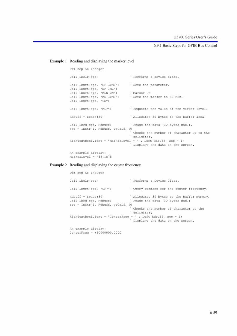
U3700 Series User’s Guide
6.9.1 Basic Steps for GPIB Bus Control
6-59
Example 1 Reading and displaying the marker level
Dim sep As Integer
Call ibclr(spa) ’ Performs a device clear.
Call ibwrt(spa, "CF 30MZ") ’ Sets the parameter.Call ibwrt(spa, "SP 1MZ")Call ibwrt(spa, "MLN ON") ’ Marker ONCall ibwrt(spa, "MK 30MZ") ’ Sets the marker to 30 MHz.Call ibwrt(spa, "TS")
Call ibwrt(spa, "ML?") ’ Requests the value of the marker level.
Rdbuff = Space(30) ’ Allocates 30 bytes to the buffer area.
Call ibrd(spa, Rdbuff) ’ Reads the data (30 bytes Max.).sep = InStr(1, Rdbuff, vbCrLf, 0)
’ Checks the number of character up to the ’ delimiter.
RichTextBox1.Text = "MarkerLevel = " & Left(Rdbuff, sep - 1)’ Displays the data on the screen.
An example display:MarkerLevel = -88.1875
Example 2 Reading and displaying the center frequency
Dim sep As Integer
Call ibclr(spa) ’ Performs a Device Clear.
Call ibwrt(spa, "CF?") ’ Query command for the center frequency.
Rdbuff = Space(30) ’ Allocates 30 bytes to the buffer memory.Call ibrd(spa, Rdbuff) ’ Reads the data (30 bytes Max.)sep = InStr(1, Rdbuff, vbCrLf, 0)
’ Checks the number of character to the ’ delimiter.
RichTextBox1.Text = "CenterFreq = " & Left(Rdbuff, sep - 1)’ Displays the data on the screen.
An example display:CenterFreq = +30000000.0000

U3700 Series User’s Guide
6.9.1 Basic Steps for GPIB Bus Control
6-60
Example 3 Reading the level and display unit and displaying them
Dim sep As Integer
Call ibclr(spa) ’ Performs a Device Clear.
Call ibwrt(spa, "RL?") ’ Query command for the reference level.
Rdbuff = Space(30) ’ Allocates 30 bytes to the buffer memory.Call ibrd(spa, Rdbuff) ’ Reads the data from the spectrum analyzer.sep = InStr(1, Rdbuff, vbCrLf, 0)
’ Checks the number of characters to the ’ delimiter.
RichTextBox1.Text = "RefLevel = " & Left(Rdbuff, sep - 1)’ Display the data on the screen.
Call ibwrt(spa, "AUNITS?") ’ Requests the level unit.
Rdbuff = Space(3)Call ibrd(spa, Rdbuff)sep = InStr(1, Rdbuff, vbCrLf, 0)
’ Checks the number of characters to the ’ delimiter.
RichTextBox1.Text = RichTextBox1.Text & vbCrLf & "UNIT = " & Left(Rdbuff, sep- 1)’ Displays the previous result, followed by a ’ return mark and the most recent result.
An example display:RefLevel = +0.0000UNIT = 0
Example 4 Executing the 6 dB-down operation, reading the frequency and level and displaying them
Dim sep As Integer
Call ibclr(spa) ’ Performs a Device Clear.
Call ibwrt(spa, "CF 30MZ") ’ Sets the parameter.Call ibwrt(spa, "SP 20MZ")
Call ibwrt(spa, "MKBW 6DB") ’ Sets a 6 dB down measurement.Call ibwrt(spa, "PS") ’ Executes the peak search.Call ibwrt(spa, "XDB") ’ Performs the 6 dB down measurement.Call ibwrt(spa, "MFL?") ’ Requests the value of the marker level and
’ frequency.
Rdbuff = Space(50) ’ Allocates the buffer memory space to 50 ’ bytes.
Call ibrd(spa, Rdbuff) ’ Reads the data (50 bytes Max.) from the ’ spectrum analyzer.
sep = InStr(1, Rdbuff, vbCrLf, 0)’ Checks the number of characters to the ’ delimiter.
RichTextBox1.Text = "Marker Freq & Level = " & Left(Rdbuff, sep - 1)’ Displays the data on the screen.
An example display:Marker Freq & Level = +2.000000000000E+05, +1.023437500000E+00

U3700 Series User’s Guide
6.9.1 Basic Steps for GPIB Bus Control
6-61
Example 5 Measuring OBW and displaying it
Dim LENG1 As Integer, LENG2 As IntegerDim OBW As StringDim FC As StringDim searchchar As String
Call ibclr(spa) ’ Performs a device clear.
Call ibwrt(spa, "CF 30MZ") ’ Sends the command already set.Call ibwrt(spa, "SP 1MZ")Call ibwrt(spa, "MLN ON") ’ Marker ONCall ibwrt(spa, "MK 30MZ")Call ibwrt(spa, "OBWON ON")Call ibwrt(spa, "TS")
Call ibwrt(spa, "OBW?") ’ Sends the query command.Rdbuff = Space(60) ’ Allocates the area to the read buffer.Call ibrd(spa, Rdbuff) ’ Reads the read buffer (the maximum number of
’ bytes to be output is determined by the buffer ’ area size).
’ Formatting output character stringLENG1 = InStr(1, Rdbuff, Chr(44), 0)
’ Searches for the first comma.FC = Mid(Rdbuff, 1, LENG1 - 1) ’ Reads the character before the comma.
DoEvents
LENG2 = InStr((LENG1 + 1), Rdbuff, Chr(13), 0)’ Determines the last data by searching for the ’ delimiter.
OBW = Mid(Rdbuff, (LENG1 + 1), (LENG2 - LENG1-1))’ Reads the data between the second comma and ’ the delimiter.
RichTextBox1.Text = "OBW = " & OBW & vbCrLf & "Fc = " & FC & vbCrLf’ Displays the data on the screen.
An example display:OBW = +9.810000000000E+05FC = +3.000250000000E+07

U3700 Series User’s Guide
6.9.1 Basic Steps for GPIB Bus Control
6-62
Example 6 Reading and displaying the three largest peak levels
Dim pk1 As String, pk2 As String, pk3 As String
Call ibclr(spa) ’ Performs a device clear.Call ibwrt(spa, "CF 0MZ") ’ Applies the settings.Call ibwrt(spa, "SP 100MZ")Call ibwrt(spa, "TS")Call ibwrt(spa, "PS") ’ Executes the peak search.Call ibwrt(spa, "ML?") ’ Query command to search for the marker levelRdbuff = Space(25) ’ Allocates the buffer memory.Call ibrd(spa, Rdbuff) ’ Receives the output.pk1 = LeftB(Rdbuff, (InStrB(1, Rdbuff, Chr(13), 1) - 1))
’ Reads the data between the starting point and ’ the delimiter.
Call ibwrt(spa, "NXP") ’ Searches for the next peak.Call ibwrt(spa, "ML?")Rdbuff = Space(25)Call ibrd(spa, Rdbuff)pk2 = LeftB(Rdbuff, (InStrB(1, Rdbuff, Chr(13), 1) - 1))
’ Reads the data between the starting point and ’ the delimiter.
Call ibwrt(spa, "NXP")Call ibwrt(spa, "ML?")Rdbuff = Space(25)Call ibrd(spa, Rdbuff)pk3 = LeftB(Rdbuff, (InStrB(1, Rdbuff, Chr(13), 1) - 1))
’ Reads the data between the starting point and ’ the delimiter.
RichTextBox1.Text = "1st PK = " & pk1 & vbCrLf & "2nd PK = " & pk2 & vbCrLf &"3rd PK = " & pk3 & vbCrLf’ Displays the data on the screen.
An example display:1st PK = -8.553906250000E+012nd PK = -7.004687500000E+013rd PK = -8.655468750000E+01

U3700 Series User’s Guide
6.9.1 Basic Steps for GPIB Bus Control
6-63
6.9.1.4 Sample Programs for Inputting or Outputting Trace Data
Trace data on the screen includes data for 501 or 1001 points on the frequency axis. For inputting and out-putting data, it is necessary to transfer data for 501 or 1001 points from the left side (start frequency) inorder. Each point level is expressed by an integer from 1792 to 14592 (however, if the trace exceeds theupper limit of the vertical scale, a value greater than 14592 is transferred).
Figure 6-7 Relationship between the Screen Graticule and Trace Data
Trace data can be input or output in either ASCII or binary format.
Specify the output by using 16-bit integer data or the absolute value when outputting a value with binarydata.For the "FORM1" or "FORM3" format, transfer data in order from the high-order byte of the data. For the"FORM2" or "FORM4" format, transfer data in order from the low-order byte.
NOTE: Only "dB" can be used as a unit for the absolute value output.When the Units setting is Watts or Volts, a value with a unit of dBm is output.
14592
1792
Trac
e da
ta v
alue
Number of data points
10019018017016015014013012011011(501)(451)(401)(351)(301)(251)(201)(151)(101)(51)

U3700 Series User’s Guide
6.9.1 Basic Steps for GPIB Bus Control
6-64
Table 6-4 Trace Point Specification Codes
GPIB Code Description
TPS Sets the number of measurement points to 501.
TPL Sets the number of measurement points to 1001.
Table 6-5 Binary Data Output Format Specified Code
GPIB code Description Byte order
FORM1 (*1) 16-bit integer value from 1792 to 14592
FORM2 (*2) 16-bit integer value from 1792 to 14592 Order swap
FORM3 (*2) Absolute value IEEE 32 bit floating-point type
FORM4 (*2) Absolute value IEEE 32 bit floating-point type Order swap
*1: When not specified, FORM1 is used.*2: The input format cannot be specified.

U3700 Series User’s Guide
6.9.1 Basic Steps for GPIB Bus Control
6-65
Table 6-6 I/O Format
I/O format Description
ASCII format DDDDD CR LF
Five-byte data without header
Input GPIB code Output GPIB code
Memory AMemory BMemory C
TAATABTAC
TAA?TAB?TAC?
Binary format16 bit-integer
FORM1DD DD .......... DD DD + EOI
FORM2DD DD .......... DD DD + EOI
Each point data is divided into two parts: high-and low-order bytes. EOI signal is attached at the end of the data for continuous 1001 points.
Input GPIB code Output GPIB code
Memory A TBA TBA?
Memory B TBB TBB?
Memory C TBC TBC?
DelimiterData for one point
Delimiter
High-order byte for 1001/501st point
Low-order byte for 1001/501st point
High-order byte for 1st point
Low-order byte for 1st point
Delimiter
Low-order byte for 1001/501st point
High-order byte for 1001/501st point
Low-orderr byte for 1st point
High-order byte for 1st point

U3700 Series User’s Guide
6.9.1 Basic Steps for GPIB Bus Control
6-66
Table 6-7 Absolute Value Output Format
I/O format Description
Binary format32-bit floating point
FORM3DD DD DD DD .......... DD DD DD DD + EOI
For DDDDDDDD=12345678, data is output in order from 12345678.
FORM4DD DD DD DD .......... DD DD DD DD + EOI
For DDDDDDDD=12345678, data is output in order from 78563412.
Each point data is 32-bit (4 bytes) floating-point type. EOI signal is attached at the end of the data for continuous 1001 points.
Output GPIB code
Memory A TBA?
Memory B TBB?
Memory C TBC?
Delimiter
High-order byte for 1001/501st point
Low-order byte for 1001/501st point
High-order byte for 1st point
Low-order byte for 1st point
Delimiter
Low-order byte for 1001/501st point
High-order byte for 1001/501st point
Low-order byte for 1st point
High-order byte for 1st point

U3700 Series User’s Guide
6.9.1 Basic Steps for GPIB Bus Control
6-67
Example 1 Read the trace data in ASCII format
Dim tr(1000) As String ’ Allocates an array in the buffer for 1001 ’ points.
Dim i As IntegerDim res As String
Call ibclr(spa) ’ Performs a Device Clear.
Call ibwrt(spa, "DLIM0") ’ CR LF EOICall ibwrt(spa, "TAA?")
For i = 0 To 1000 Step 1 ’ Repeats the operation for 1001 points.tr(i) = Space(7) ’ Allocates 7 bytes (5 bytes for the data, and
’ 2 bytes for delimiters).Call ibrd(spa, tr(i)) ’ Reads the data.
’ Displays the data on the screen.res = res & "tr(" & Str(i) & ") = " & Left(tr(i), 5) & vbCrLfDoEvents
Next i
RichTextBox1.Text = res
Example 2 Reading the memory A data in binary format
Dim tr(1000) As Integer ’ Allocates an array in the buffer for 1001 ’ points.
Dim i As IntegerDim res As StringDim Rslt As Integer, tmp As Integer
Call ibclr(spa) ’Performs a device clear.Call ibconfig(0, IbcEndBitIsNormal, 0)
’ Sets the GPIB-board software so that the end ’ bit of the Ibsta variable is set to 1 only ’ when EOI has been received.
Call ibwrt(spa, "DLIM2") ’ Sets the delimiter to EOI only.Call ibwrt(spa, "TBA?") ’ Requests Trace A in binary data.Call ibrdi(spa, tr(), 1001 * 2)’ Reads 1001 points of binary data.For i = 0 To 1000 Step 1 ’ Repeats the operation for 1001 points. tmp = tr(i) ’ Swaps the high and low bites. Rslt = (tmp And &HFF&) * 256 Rslt = Rslt + ((tmp And &HFF00&) / 256) res = res & Str(Rslt) & vbCrLf
’Displays the data on the screen. DoEventsNext iRichTextBox1.Text = resCall ibwrt(spa, "DLIM0") ’Sets the delimiter to the CR, LF and EOI.Call ibconfig(0, IbcEndBitIsNormal, 1)

U3700 Series User’s Guide
6.9.1 Basic Steps for GPIB Bus Control
6-68
Example 3 Entering data into memory A in ASCII format
Dim trdata(1000) As IntegerDim i As Integer
trdata(0) = 1792 ’ Creates a temporary test value used to test ’ the input (*).
For i = 1 To 1000 Step 1trdata(i) = Str(Val(trdata(i - 1)) + 12)DoEvents
Next i ’ If measurement data exists, the steps between ’ the place marked with (*) and this point are ’ not required.
Call ibclr(spa) ’ Performs a device clear.Call ibwrt(spa, "AB") ’ Sets Trace A to BLANK.Call ibwrt(spa, "TAA") ’ Sets Trace A in ASCII.
For i = 0 To 1000 Step 1 ’ Repeats the operation for 1001 points.Call ibwrt(spa, CStr(trdata(i)))
’ Sends the value after it has been converted ’ to the ASCII data.
DoEventsNext i
Call ibwrt(spa, "AV") ’ Sets Trace A to VIEW.
<Program example of absolute value output>
When using FORM3, add the line shown below to NIGLOBAL.The CopyValtoVal API function is required to shift 32 bits.
Declare Sub CopyValtoVal Lib "kernel32" Alias "RtlMoveMemory" (Destination As Any, Source As Any, ByVal length As Long)
Example 4 FORM2 Reading the memory A data in binary 16-bit integer (order swap)
Dim tr(1000) As Integer ’ Allocates an array in the buffer for 1001 ’ points.
Dim i As IntegerDim res As String
Call ibclr(spa) ’ Performs a Device Clear.Call ibwrt(Spa, "FORM2") ’ Switches to FORM2.Call ibconfig(0, IbcEndBitIsNormal, 0)
’ Sets the GPIB-board software so that the end ’ bit of each Ibsta variable is set to 1 only ’ when EOI has been received.
Call ibwrt(Spa, "DLIM2") ’ Sets a delimiter to EOI only.Call ibwrt(Spa, "TBA?") ’ Requests Trace A in binary data.
Call ibrdi(Spa, tr(), 1001 * 2)’ Reads 1001 points of binary data.
For i = 0 To 1000 Step 1 ’ Repeats the operation for 1001 points. res = res & Str(tr(i)) & vbCrLf
’ Displays the data on the screen. DoEventsNext iRichTextBox1.Text = res Call ibwrt(Spa, "DLIM0") ’ Sets the delimiter to the CR, LF and EOI.Call ibconfig(0, IbcEndBitIsNormal, 1)
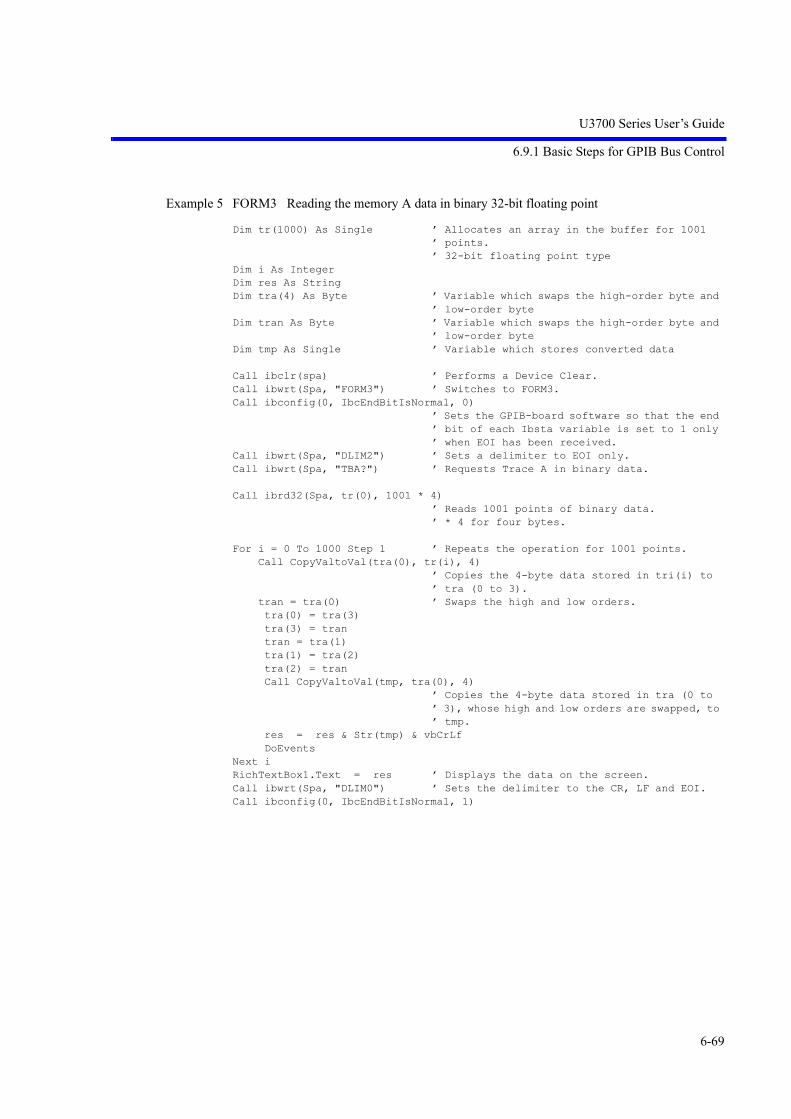
U3700 Series User’s Guide
6.9.1 Basic Steps for GPIB Bus Control
6-69
Example 5 FORM3 Reading the memory A data in binary 32-bit floating point
Dim tr(1000) As Single ’ Allocates an array in the buffer for 1001 ’ points.’ 32-bit floating point type
Dim i As IntegerDim res As StringDim tra(4) As Byte ’ Variable which swaps the high-order byte and
’ low-order byteDim tran As Byte ’ Variable which swaps the high-order byte and
’ low-order byteDim tmp As Single ’ Variable which stores converted data
Call ibclr(spa) ’ Performs a Device Clear.Call ibwrt(Spa, "FORM3") ’ Switches to FORM3.Call ibconfig(0, IbcEndBitIsNormal, 0)
’ Sets the GPIB-board software so that the end ’ bit of each Ibsta variable is set to 1 only ’ when EOI has been received.
Call ibwrt(Spa, "DLIM2") ’ Sets a delimiter to EOI only.Call ibwrt(Spa, "TBA?") ’ Requests Trace A in binary data.
Call ibrd32(Spa, tr(0), 1001 * 4)’ Reads 1001 points of binary data.’ * 4 for four bytes.
For i = 0 To 1000 Step 1 ’ Repeats the operation for 1001 points. Call CopyValtoVal(tra(0), tr(i), 4)
’ Copies the 4-byte data stored in tri(i) to ’ tra (0 to 3).
tran = tra(0) ’ Swaps the high and low orders. tra(0) = tra(3) tra(3) = tran tran = tra(1) tra(1) = tra(2) tra(2) = tran Call CopyValtoVal(tmp, tra(0), 4)
’ Copies the 4-byte data stored in tra (0 to ’ 3), whose high and low orders are swapped, to ’ tmp.
res = res & Str(tmp) & vbCrLf DoEventsNext iRichTextBox1.Text = res ’ Displays the data on the screen.Call ibwrt(Spa, "DLIM0") ’ Sets the delimiter to the CR, LF and EOI.Call ibconfig(0, IbcEndBitIsNormal, 1)

U3700 Series User’s Guide
6.9.1 Basic Steps for GPIB Bus Control
6-70
Example 6 FORM4 Reading the memory A data in binary 32-bit floating point (order swap)
Dim tr(1000) As Single ’ Allocates an array in the buffer for 1001 ’ points.’ 32-bit floating point type
Dim i As IntegerDim res As String
Call ibclr(spa) ’ Performs a Device Clear.Call ibwrt(Spa, "FORM4") ’ Switches to FORM3.Call ibconfig(0, IbcEndBitIsNormal, 0)
’ Sets the GPIB-board software so that the end ’ bit of each Ibsta variable is set to 1 when ’ EOI has been received.
Call ibwrt(Spa, "DLIM2") ’ Sets a delimiter to EOI only.Call ibwrt(Spa, "TBA?") ’ Requests Trace A in binary data.
Call ibrd32(Spa, tr(0), 1001 * 4)’ Reads 1001 points of binary data.’ * 4 for four bytes.
For i = 0 To 1000 Step 1 ’ Repeats the operation for 1001 points. res = res & Str(tr(i)) & vbCrLf
’ Displays the data on the screen. DoEventsNext iRichTextBox1.Text = resCall ibwrt(Spa, "DLIM0") ’ Sets the delimiter to the CR, LF and EOI.Call ibconfig(0, IbcEndBitIsNormal, 1)
6.9.1.5 Example Program for Screen Image Output
Example 1 Outputs a current screen image as bitmap data and writes it to a file.Data, which is approximately 150 KB for the BMP format or approximately 5 KB for the PNGformat, is output.
Call ibclr(spa) ’ Performs a Device Clear.
Call ibwrt(spa, "DLIM2") ’ Sets a delimiter to EOI only.Call ibwrt(spa, "BMP?") ’ Requests bitmap data output.Call ibrdf(spa, "bitmap.bmp") ’ Writes bitmap data to a file.Call ibwrt(spa, "DLIM0") ’ Returns delimiter setting to CR, LF and EOI.
Example 2 Writes a screen image that is copied into a USB memory to a file.
Call ibclr(spa) ’ Performs a Device Clear.
Call ibwrt(spa, "DLIM2") ’ Sets a delimiter to EOI only.Call ibwrt(spa, "GIMAG :copy003.bmp")
’ Specifies a screen image name and requests’ its output.
Call ibrdf(spa, "copy003.bmp") ’ Writes a screen image to a file.Call ibwrt(spa, "DLIM0") ’ Returns delimiter setting to CR, LF and EOI.

U3700 Series User’s Guide
6.9.1 Basic Steps for GPIB Bus Control
6-71
6.9.1.6 Example Program Which Uses the TS (Take Sweep) Command
Example 1 An ACP measurement is taken and then the measurement result is read (using the TS com-mand).
Dim state As IntegerDim sep1 As Integer, sep2 As IntegerDim i As Integer, j As IntegerDim cnt As IntegerDim LvlH As String, LvlL As StringDim FrqH As String, FrqL As String
Call ibclr(spa) ’ Performs a Device Clear.
Call ibwrt(spa, "SI") ’ Sets the single mode.Call ibwrt(spa, "CF 1500MZ") ’ Sets the center frequency to 1500 MHz.Call ibwrt(spa, "SP 250KZ") ’ Sets the frequency span to 250 kHz.Call ibwrt(spa, "RB 1KZ") ’ Sets RBW to 1 kHz.Call ibwrt(spa, "VB 3KZ") ’ Sets VBW to 3 kHz.Call ibwrt(spa, "ST 20SC") ’ Sets the sweep time to 20 sec.Call ibwrt(spa, "CSBSDEL") ’ Clears the channel space and bandwidth
’ previously set.Call ibwrt(spa, "CSBSIN 50KZ,21KZ")
’ Sets CS to 50 kHz, and BS to 21 kHz.Call ibwrt(spa, "ACP ON") ’ Starts the ACP measurement.
For j = 1 To 10 Step 1Call ibwrt(spa, "TS") ’ Executes one sweep.Call ibwrt(spa, "ACP?") ’ Requests the result of the ACP measurement.Rdbuff = Space(3) ’ Assigns 1 byte for an integer and 2 bytes for
’ a delimiter before reading the result.Call ibrd(spa, Rdbuff) ’ Reads the data.cnt = CInt(Rdbuff) ’ Converts the contents of the buffer into
’ integers.
For i = 1 To cnt Step 1Rdbuff = Space(81) ’ Assigns an area of 81 bytes (Real number x 4
’ + ',' x 3 + CRLF).Call ibrd(spa, Rdbuff) ’ Reads the data.
sep1 = InStr(1, Rdbuff, ",", 0)’ Searches for the first comma starting from ’ the top of the buffer.
FrqL = Left(Rdbuff, sep1 - 1)’ Reads the string between the top and the ’ character string.
sep2 = InStr(sep1 + 1, Rdbuff, ",", 0)’ Searches for the next comma.
LvlL = Mid(Rdbuff, sep1 + 1, sep2 - sep1 - 1)’ Reads the string between the first and second ’ commas.
sep1 = InStr(sep2 + 1, Rdbuff, ",", 0)’ Searches for the next comma.
FrqH = Mid(Rdbuff, sep2 + 1, sep1 - sep2 - 1)’ Reads the string between the second and third ’ commas.
sep2 = InStr(sep1, Rdbuff, Chr(13), 0)’ Searches for the terminator (CR).
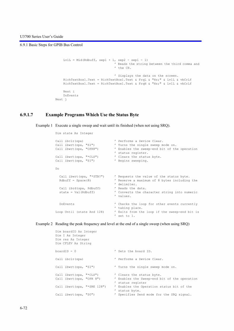
U3700 Series User’s Guide
6.9.1 Basic Steps for GPIB Bus Control
6-72
LvlL = Mid(Rdbuff, sep1 + 1, sep2 - sep1 - 1)’ Reads the string between the third comma and ’ the CR.
’ Displays the data on the screen.RichTextBox1.Text = RichTextBox1.Text & FrqL & "Hz;" & LvlL & vbCrLfRichTextBox1.Text = RichTextBox1.Text & FrqH & "Hz;" & LvlL & vbCrLf
Next iDoEvents
Next j
6.9.1.7 Example Programs Which Use the Status Byte
Example 1 Execute a single sweep and wait until its finished (when not using SRQ).
Dim state As Integer
Call ibclr(spa) ’ Performs a Device Clear.Call ibwrt(spa, "SI") ’ Turns the single sweep mode on.Call ibwrt(spa, "OPR8") ’ Enables the sweep-end bit of the operation
’ status register.Call ibwrt(spa, "*CLS") ’ Clears the status byte.Call ibwrt(spa, "SI") ’ Begins sweeping.
Do
Call ibwrt(spa, "*STB?") ’ Requests the value of the status byte.Rdbuff = Space(8) ’ Reserve a maximum of 8 bytes including the
’ delimiter.Call ibrd(spa, Rdbuff) ’ Reads the data.state = Val(Rdbuff) ’ Converts the character string into numeric
’ values.
DoEvents ’ Checks the loop for other events currently ’ taking place.
Loop Until (state And 128) ’ Exits from the loop if the sweep-end bit is ’ set to 1.
Example 2 Reading the peak frequency and level at the end of a single sweep (when using SRQ)
Dim boardID As IntegerDim I As IntegerDim res As IntegerDim CFLEV As String
boardID = 0 ’ Sets the board ID.
Call ibclr(spa) ’ Performs a Device Clear.
Call ibwrt(spa, "SI") ’ Turns the single sweep mode on.
Call ibwrt(spa, "*CLS") ’ Clears the status byte.Call ibwrt(spa, "OPR 8") ’ Enables the Sweep-end bit of the operation
’ status registerCall ibwrt(spa, "*SRE 128") ’ Enables the Operation status bit of the
’ status byte.Call ibwrt(spa, "S0") ’ Specifies Send mode for the SRQ signal.

U3700 Series User’s Guide
6.9.1 Basic Steps for GPIB Bus Control
6-73
For I = 1 To 10 Step 1 ’ Sets up a 10-loop.Call ibwrt(spa, "SI") ’ Begins sweeping.Call WaitSRQ(boardID, res) ’ Waits until SRQ interruption occurs.Call ibrsp(spa, res) ’ Executes serial polling.
Call ibwrt(spa, "PS") ’ Executes the peak search.Call ibwrt(spa, "MFL?") ’ Request the values of the marker frequency
’ and level.
Rdbuff = Space(43) ’ Reserves 43 bytes.Call ibrd(spa, Rdbuff) ’ Reads the data.
CFLEV = Left(Rdbuff, InStr(1, Rdbuff, Chr(13), 0) - 1)RichTextBox1.Text = RichTextBox1.Text & "Freq ,Level = " & CFLEV & vbCrLf
’ Display data on the screen and start a new ’ line.
DoEvents ’ Executes any other events in Windows.Next I
6.9.1.8 Program Examples Using the LAN
Example 1 Connection LAN Interface
Public Sub ConnectTCP( )Dim Ini as String tcpClient.RemoteHost = "192.168.1.1"
’ Sets IP Address of SAtcpClient.Protocol = sckTCPProtocol
’ Sets protocol to TCPtcpClient.RemotePort = 5025 ’ Sets port no. 5025 of SAtcpClient.Connect ’ Connects to SA's port
Do While (tcpClient.BytesReceived = 0)’Waits connection
DoEventsLooptcpClient.GetData IniErrRet = SendDtFunc("REN" & vbLf)
’Remote enable
End Sub
Example 2 Initialize Spectrum Analyzer
Public Sub InitSA( )tcpClient.SendData "*CLS" & vbLf
’ Resets status registertcpClient.SendData "*RST" & vbLf
’ Resets this instrumentEnd Sub

U3700 Series User’s Guide
6.9.1 Basic Steps for GPIB Bus Control
6-74
Example 3 Brief setting of Spectrum Analyzer(Set Center freq. to 1.9984 GHz, Span to 10 MHz and Reference level to 10 dBm)
Public Sub SASetting( )tcpClient.SendData "CF 1.9984GZ" & vbLftcpClient.SendData "SP 10MZ" & vbLftcpClient.SendData "RL 10DB" & vbLfEnd Sub
Example 4 Read the setting value of Spectrum Analyzer
Public Sub ReadSASetting( )CF$= Space$(20) ’ Prepares the text variable for readtcpClient.SendData "CF?" & vbLf’ Reads request of center freq.Do While (tcpClient.BytesReceived = 0)
’ Waits for receiving a characterDoEvents
LooptcpClient.GetData CF$ ’ Reads setting valueSP$= Space$(20) ’ Prepares the text variable for readtcpClient.SendData "SP?" & vbLf’ Reads request of span freq.Do While (tcpClient.BytesReceived = 0)
’ Waits for receiving a characterDoEvents
LooptcpClient.GetData SP$ ’ Reads setting value
Example 5 Display setting value
Call MsgBox( "Center freq.: " & CF$ & "Span freq.: " & SP$)End Sub
Example 6 Read signal level using the marker function
Public Sub ReadMkrSignal( )MKLevel$= Space$(20) ’ Prepares the text variable for readtcpClient.SendData "MLN ON"& vbLf
’ Turns on the markertcpClient.SendData "PS" & vbLf ’ Searches peak point of signaltcpClient.SendData "MF?" & vbLf’ Query the marker frequencyDo While (tcpClient.BytesReceived = 0)
’ Waits for receiving a characterDoEvents
LooptcpClient.GetData MKFreq$ ’ Reads ittcpClient.SendData "ML?" & vbLf’ Query the marker levelDo While (tcpClient.BytesReceived = 0)
’ Waits for receiving a characterDoEvents
LooptcpClient.GetData MKlevel$ ’ Reads it
Example 7 Display the freq. and level of signal
Call MsgBox("Marker freq.: " & MKFreq$ & " Level: " & MKLevel$)End Sub

U3700 Series User’s Guide
6.9.1 Basic Steps for GPIB Bus Control
6-75
Example 8 Measure Adjacent Channel Power
Public Sub MeasACP( )ResultACP$ = Space(200)tcpClient.SendData "CF 2GZ" & vbLf’ Sets carrier freq.tcpClient.SendData "SP 25MZ" & vbLf
Example 9 Setting of Adjacent channel parameters
tcpClient.SendData "CSBSDEL" & vbLf’ Clears Channel Space param.
tcpClient.SendData "ACPSCR CARR"& vbLf’ Sets ACP mode to Carrier
tcpClient.SendData "CARRBS 3.84MHz"& vbLf’ Sets Channel Bandwidth
tcpClient.SendData "CSBSIN 5MZ,3.84MZ" & vbLf’Adj. Channel param.
tcpClient.SendData "CSBSIN 10MZ,3.84MZ" & vbLf’ Adj. Channel param.
Example 10 Setting of Root Nyquist filter's parameters
tcpClient.SendData "ACPNQST ON" & vbLf’ Sets Nyq. Filter operation to on
tcpClient.SendData "SYMRT 3.84MZ" & vbLf’ Sets Symbol rate of filter
tcpClient.SendData "RFACT 0.22" & vbLf’ Sets Roll off factor of filter
tcpClient.SendData "ACPTM 10" & vbLf’ Sets average times
tcpClient.SendData "PMEASAVG ON" & vbLf’ Sets average func. to ON
tcpClient.SendData "ACP" & vbLf’ Starts measurementtcpClient.SendData "*CLS;OPR 16;*SRE 128" & vbLf
’Sets status byteStb$ = Space(10)Do
tcpClient.SendData "*STB?" + vbLfDo While (tcpClient.BytesReceived = 0)
’ Waits for receiving a characterDoEvents
LooptcpClient.GetData StbIf CLng(Val(Stb)) And 128 Then Exit Do
Loop
tcpClient.SendData "ACP?" + vbLftcpClient.GetData ResultACP$ ’ Reads out all meas. results of ACPCall MsgBox("ACP results : " & ResultACP$)End Sub

U3700 Series User’s Guide
6.10 SCPI Command Reference
6-76
6.10 SCPI Command Reference
This chapter describes the SCPI command reference for this instrument.
6.10.1 Command Reference Syntax
This section describes the function, syntax, and parameter of each SCPI command discussed in this chap-ter.
• [Function description]How to use a command or operations when the command is executed are described.
• [SCPI command]Syntax when the command is sent from an external controller to this instrument is described.Example: Marker setting
1. The syntax consists of a command section and parameter section. The command section and parameter section are delimited by a space.
2. #1, #2, and @3 are parameters required for sending a command. A number that follows on # or @ corresponds to a row number in the parameter column. The # parameter may be omitted. If omitted, the parameter is set to 1. The @ parameter cannot be omitted.
3. Lowercase alphabetical characters written in syntax can be omitted.
4. [ ] shows that the command is optional. This command can be omitted.
5. "|" shows that only one item is required to be selected from multiple items.
Function description SCPI command Parameter Query replyEnable Marker :CALCulate#1:MARKer#2:STATe @3
$1 = :CALCulate#1:MARKer#2:STATe?
Context index, Marker index, ON|OFF
1|0
Space#1#2@3

U3700 Series User’s Guide
6.10.1 Command Reference Syntax
6-77
• [Parameter]Following parameters from 1 to 7 can be omitted:
1. Context Index1|2|0
1 = Context A (RF2)2 = Context B (RF1)0 = Active context
2. Marker Index1|2|3|4|5|6|7|8|9|10|00 = Active marker
3. Trace Index1|2|3|0
1 = Trace A 2 = Trace B 3 = Trace C0 = Active trace
4. Limit Line Index1|2
5. SEM channel Index1|2|3|4|5|
6. Spurious band Index1|2|3|4|5|6|7|8|9|10|11|12|13|14|15
7. Spurious Table Index1|2|3
8. Intermodulation Order Index3|5|7|9This parameter cannot be omitted.
• [Query reply]
1. $1This query reply shows that one variable is replied.For this example, 1 or 0 is replied.
2. Example of a query reply consisting of multiple variables$1,$2,$3,$4=*IDN?
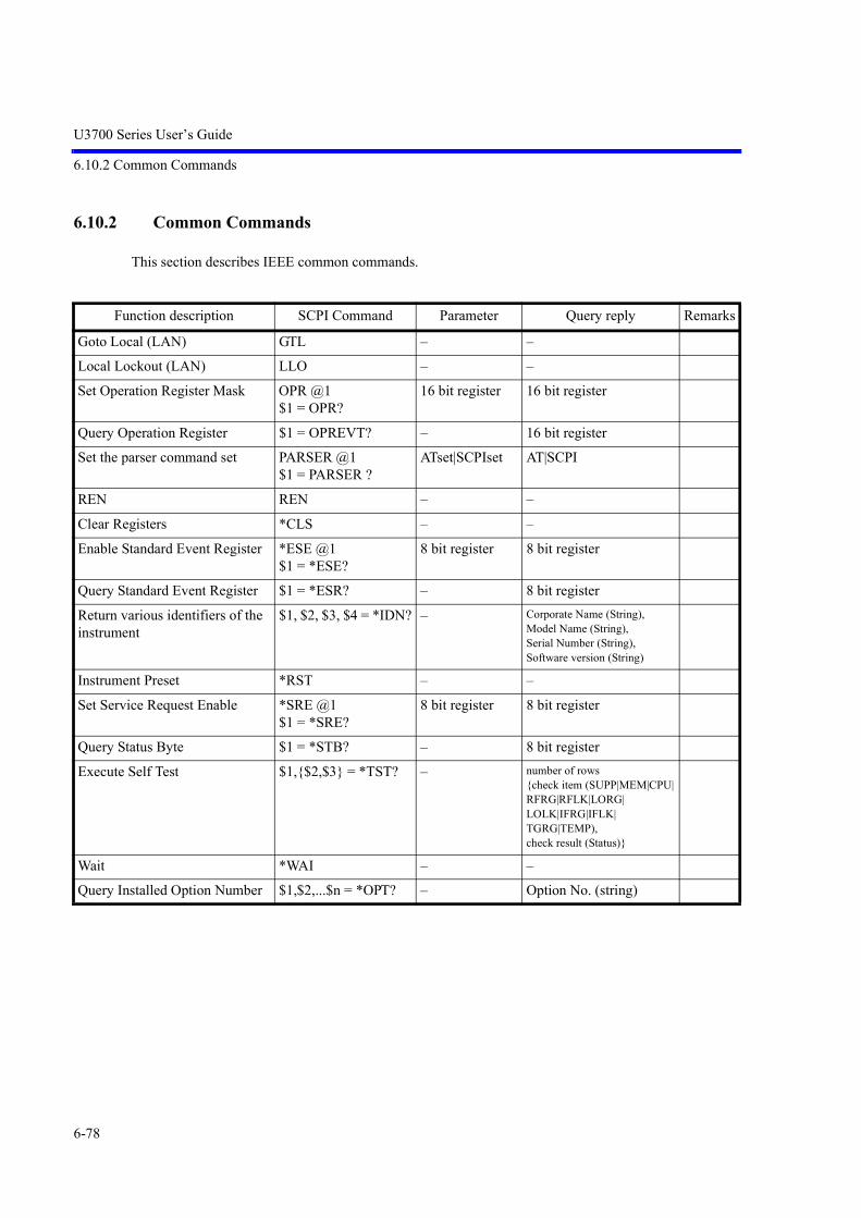
U3700 Series User’s Guide
6.10.2 Common Commands
6-78
6.10.2 Common Commands
This section describes IEEE common commands.
Function description SCPI Command Parameter Query reply Remarks
Goto Local (LAN) GTL – –
Local Lockout (LAN) LLO – –
Set Operation Register Mask OPR @1$1 = OPR?
16 bit register 16 bit register
Query Operation Register $1 = OPREVT? – 16 bit register
Set the parser command set PARSER @1$1 = PARSER ?
ATset|SCPIset AT|SCPI
REN REN – –
Clear Registers *CLS – –
Enable Standard Event Register *ESE @1$1 = *ESE?
8 bit register 8 bit register
Query Standard Event Register $1 = *ESR? – 8 bit register
Return various identifiers of the instrument
$1, $2, $3, $4 = *IDN? – Corporate Name (String), Model Name (String), Serial Number (String), Software version (String)
Instrument Preset *RST – –
Set Service Request Enable *SRE @1$1 = *SRE?
8 bit register 8 bit register
Query Status Byte $1 = *STB? – 8 bit register
Execute Self Test $1,{$2,$3} = *TST? – number of rows {check item (SUPP|MEM|CPU|RFRG|RFLK|LORG|LOLK|IFRG|IFLK|TGRG|TEMP), check result (Status)}
Wait *WAI – –
Query Installed Option Number $1,$2,...$n = *OPT? – Option No. (string)

U3700 Series User’s Guide
6.10.3 List of Commands
6-79
6.10.3 List of Commands
6.10.3.1 Subsystem-CALCulate
Function description SCPI command Parameter Query reply Remarks
Set Center Frequency From Delta Marker Postion Difference
:CALCulate#1:MARKer#2:DELTa[:SET]:CENTer
Context index, Marker index
--
Set Marker Step From Marker Delta Position Difference
:CALCulate#1:MARKer#2:DELTa[:SET]:MARKer:STEP
Context index, Marker index
--
Set Span From Delta Marker Position Difference
:CALCulate#1:MARKer#2:DELTa[:SET]:SPAN
Context index, Marker index
--
Set Frequency Step From Marker Delta Position Difference
:CALCulate#1:MARKer#2:DELTa[:SET]:STEP
Context index, Marker index
--
Execute X dB Down :CALCulate#1:MARKer#2:FUNCtion:XDBDown
Context index, Marker index
--
Execute X dB Left :CALCulate#1:MARKer#2:FUNCtion:XDBDown:LEFT
Context index, Marker index
--
Execute Peak Search and X dB Down :CALCulate#1:MARKer#2:FUNCtion:XDBDown:PEAK
Context index, Marker index
--
Execute X dB Right :CALCulate#1:MARKer#2:FUNCtion:XDBDown:RIGHt
Context index, Marker index
--
Get Specific Marker Information $1,$2,$3,$4 = :CALCulate#1:MARKer#2:INFO?
Context index, Marker index
marker index (Marker index), marker enable (1|0), marker position (Position (Hz|s)), marker amplitude (Amplitude)
Execute Next Peak Search to the Left :CALCulate#1:MARKer#2:MAXimum:LEFT
Context index, Marker index
--
Execute Next Peak Search :CALCulate#1:MARKer#2:MAXimum:NEXT
Context index, Marker index
--
Execute Next Peak Search to the Right :CALCulate#1:MARKer#2:MAXimum:RIGHt
Context index, Marker index
--
Execute Maximum Peak Search :CALCulate#1:MARKer#2:MAXimum[:PEAK]
Context index, Marker index
--
Execute Next Minimum Search :CALCulate#1:MARKer#2:MINimum:NEXT
Context index, Marker index
--
Execute Minimum Search :CALCulate#1:MARKer#2:MINimum[:PEAK]
Context index, Marker index
--
Execute Minimum Maximum Search :CALCulate#1:MARKer#2:PTPeak Context index, Marker index
--
Enable Marker :CALCulate#1:MARKer#2:STATe @3$1 = :CALCulate#1:MARKer#2:STATe?
Context index, Marker indexON|OFF
1|0
Select Marker Trace :CALCulate#1:MARKer#2:TRACe @3$1 = :CALCulate#1:MARKer#2:TRACe?
Context index, Marker index, Trace index
Trace index

U3700 Series User’s Guide
6.10.3 List of Commands
6-80
Set Marker Position :CALCulate#1:MARKer#2:X @3$1 = :CALCulate#1:MARKer#2:X?
Context index, Marker index, Frequency|Time
Position (Hz|s)
Get Marker Absolute Position $1 = :CALCulate#1:MARKer#2:X:ABSolute?
Context index, Marker index
Position (Hz|s)
Get Marker Coordinates $1, $2 = :CALCulate#1:MARKer#2:XY? Context index, Marker index
Position (Hz|s), amplitude (Amplitude)
Get Marker Amplitude $1 = :CALCulate#1:MARKer#2:Y? Context index, Marker index
Amplitude
Get Marker Absolute Amplitude $1 = :CALCulate#1:MARKer#2:Y:ABSolute?
Context index, Marker index
Amplitude
Set Center Frequency from Marker Position
:CALCulate#1:MARKer#2[:SET]:CENTer
Context index, Marker index
--
Set Marker Step from Marker Position :CALCulate#1:MARKer#2[:SET]:MARKer:STEP
Context index, Marker index
--
Set Reference Level from Marker Amplitude
CALCulate#1:MARKer#2[:SET]:RLEVel
Context index, Marker index
--
Set Span from Marker Delta Position Difference
:CALCulate#1:MARKer#2[:SET]:SPAN
Context index, Marker index
--
Set Center Frequency Step from Marker Position
:CALCulate#1:MARKer#2[:SET]:STEP
Context index, Marker index
--
Select Active Marker :CALCulate#1:MARKer:ACTive @2$1 = :CALCulate#1:MARKer:ACTive?
Context index, Marker index
Marker index
Query Markers List $1, {$2,$3,$4,$5} = :CALCulate#1:MARKer:ALL:INFO?
Context index number of rows {marker index (Marker index), marker enable (1|0), marker position (Position (Hz|s)), marker amplitude (Amplitude)}
Clear All Markers :CALCulate#1:MARKer:AOFF Context index --
Enable Continuous Peak Search :CALCulate#1:MARKer:CPEak[:STATe] @2$1 = :CALCulate#1:MARKer:CPEak[:STATe]?
Context index, ON|OFF
1|0
Enable Fixed Reference Marker Mode :CALCulate#1:MARKer:DELTa:FIXed[:STATe] @2$1 = :CALCulate#1:MARKer:DELTa:FIXed[:STATe]?
Context index, ON|OFF
1|0
Enable Marker Delta Mode :CALCulate#1:MARKer:DELTa[:STATe] @2$1 = :CALCulate#1:MARKer:DELTa[:STATe]?
Context index, ON|OFF
1|0
Set Center Frequency from Peak :CALCulate#1:MARKer:MAXimum[:SET]:CENTer
Context index --
Set Reference Level from Peak :CALCulate#1:MARKer:MAXimum[:SET]:RLEVel
Context index --
Set Marker Mode :CALCulate#1:MARKer:MODE @2$1 = :CALCulate#1:MARKer:MODE?
Context index, POSition|DELTa
POS|DELT
Function description SCPI command Parameter Query reply Remarks

U3700 Series User’s Guide
6.10.3 List of Commands
6-81
Set Peak Excursion :CALCulate#1:MARKer:PEAK:EXCursion @2$1 = :CALCulate#1:MARKer:PEAK:EXCursion?
Context index, Number
Number
Set the Delta Marker Reference Object :CALCulate#1:MARKer:REFerence:OBJEct @2$1 = :CALCulate#1:MARKer:REFerence:OBJEct ?
Context index, RMARker|RLINe
RMAR|RLIN
Query Reference Marker Absolute Position
$1 = :CALCulate#1:MARKer:REFerence:X?
Context index Position (Hz|s)
Query Reference Marker Absolute Amplitude
$1 = :CALCulate#1:MARKer:REFerence:Y?
Context index Amplitude
Turn Off Multi-Marker Mode :CALCulate#1:MARKer:RESet Context index --
Set X Axis Marker Search Area Mode :CALCulate#1:MARKer:SEARch:X:MODE @2$1 = :CALCulate#1:MARKer:SEARch:X:MODE?
Context index, ALL|INNer|OUTer
ALL|INN|OUT
Set X Axis Marker Search Area Center Position
:CALCulate#1:MARKer:SEARch:X:POSition @2$1 = :CALCulate#1:MARKer:SEARch:X:POSition?
Context index, Frequency|Time
Position (Hz|s)
Set X axis Marker Search Area Width :CALCulate#1:MARKer:SEARch:X:WIDTh @2$1 = :CALCulate#1:MARKer:SEARch:X:WIDTh?
Context index, Frequency|Time
Position (Hz|s)
Set the Marker Search Area Relative to the Display Line
:CALCulate#1:MARKer:SEARch:Y:DLINe @2$1 = :CALCulate#1:MARKer:SEARch:Y:DLINe?
Context index, OFF|ABOVe|BELow
OFF|ABOV|BEL
Set the Marker Search Area Relative to Limit Line 1
:CALCulate#1:MARKer:SEARch:Y:LIM#2 @3$1 = :CALCulate#1:MARKer:SEARch:Y:LIM#2?
Context index, Limit line index,OFF|ABOVe|BELow
OFF|ABOV|BEL
Set Marker Step :CALCulate#1:MARKer:STEP @2$1 = :CALCulate#1:MARKer:STEP?
Context index, Fre-quency|Time
Position (Hz|s)
Enable Marker Step Auto :CALCulate#1:MARKer:STEP:AUTO @2$1 = :CALCulate#1:MARKer:STEP:AUTO?
Context index, ON|OFF
1|0
Set Signal Track Y Ranging Excursion :CALCulate#1:MARKer:TRCKing:EXCursion @2$1 = :CALCulate#1:MARKer:TRCKing:EXCursion?
Context index, Relative amplitude
Relative amplitude
Enable Signal Track Y Ranging :CALCulate#1:MARKer:TRCKing:EXCursion:STATe @2$1 = :CALCulate#1:MARKer:TRCKing:EXCursion:STATe?
Context index, ON|OFF
1|0
Set Marker Readout Mode :CALCulate#1:MARKer:X:READout @2$1 = :CALCulate#1:MARKer:X:READout?
Context index, NORMal|INVerse
NORM|INV
Set Measuring Window Position :CALCulate#1:WINDow:POSition @2$1 = :CALCulate#1:WINDow:POSition?
Context index, Frequency|Time
Position (Hz|s)
Function description SCPI command Parameter Query reply Remarks

U3700 Series User’s Guide
6.10.3 List of Commands
6-82
Set Measuring Window Width :CALCulate#1:WINDow:WIDTh @2$1 = :CALCulate#1:WINDow:WIDTh?
Context index, Frequency|Time
Position (Hz|s)
Insert a Limit Line Vertex :CALCulate:LLINe#1:DATA @2:CALCulate:LLINe#1:DATA @2
Limit line index, X-coordinate of limit line point (Time), ordinate of limit line point (Relative amplitude)
--
Insert a Frequency Domain Limit Line Vertex
:CALCulate:LLINe#1:DATA:FREQuency @2
Limit line index, X-coordinate of table point (Frequency), ordi-nate of table point (Relative amplitude)
--
Insert a Time Domain Limit Line Ver-tex
:CALCulate:LLINe#1:DATA:TIME @2 Limit line index, X-coordinate of limit line point (Time), ordinate of limit line point (Relative amplitude)
--
Erase a Limit Line :CALCulate:LLINe#1:DELete Limit line index --
Erase a Frequency Domain Limit Line :CALCulate:LLINe#1:DELete:FREQuency
Limit line index --
Erase a Time Domain Limit Line :CALCulate:LLINe#1:DELete:TIME Limit line index --
Enable a Limit Line :CALCulate:LLINe#1:DISPlay @2$1 = :CALCulate:LLINe#1:DISPlay?
Limit line index, ON|OFF
1|0
Set Limit Lines Detection Type :CALCulate:LLINe#1:TYPE @2$1 = :CALCulate:LLINe#1:TYPE?
Limit line index, UPPer|LOWer
UPP|LOW
Set Limit Lines X axis Reference :CALCulate:LLINe:CMODe @1$1 = :CALCulate:LLINe:CMODe?
FIXed|RELative FIX|REL
Set Limit Lines X axis Reference :CALCulate:LLINe:CMODe:X @1$1 = :CALCulate:LLINe:CMODe:X?
ABSolute|CENTer|LEFT
ABS|CENT|LEFT
Set Limit Lines Frequency Offset :CALCulate:LLINe:CMODe:X:OFFSet:FREQuency @1$1 = :CALCulate:LLINe:CMODe:X:OFFSet:FREQuency?
Frequency Frequency
Enable Limit Lines X axis Offset :CALCulate:LLINe:CMODe:X:OFFSet:STATe @1$1 = :CALCulate:LLINe:CMODe:X:OFFSet:STATe?
ON|OFF 1|0
Set Limit Lines Time Offset :CALCulate:LLINe:CMODe:X:OFFSet:TIME @1$1 = :CALCulate:LLINe:CMODe:X:OFFSet:TIME?
Time Time
Select Limit Lines Y axis Positioning :CALCulate:LLINe:CMODe:Y @1$1 = :CALCulate:LLINe:CMODe:Y ?
ABSolute|TOP|DLINe
ABS|TOP|DLIN
Set Limit Lines Y axis Offset :CALCulate:LLINe:CMODe:Y:OFFSet @1$1 = :CALCulate:LLINe:CMODe:Y:OFFSet?
Relative amplitude Relative amplitude
Function description SCPI command Parameter Query reply Remarks
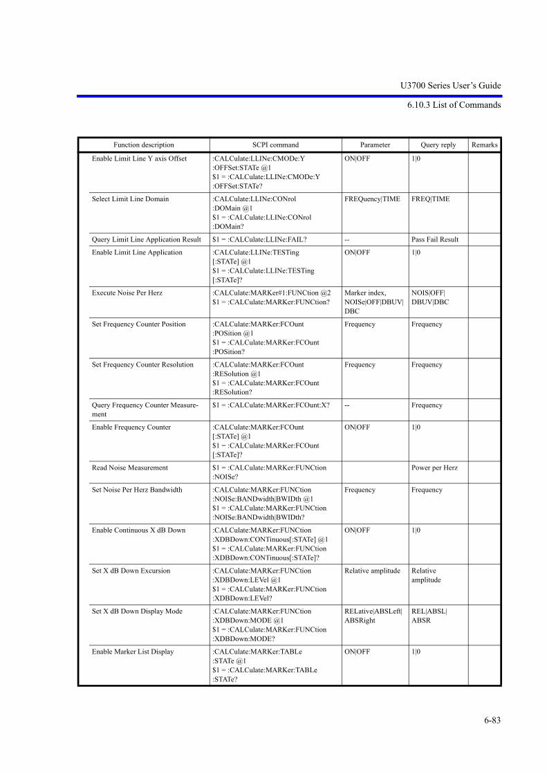
U3700 Series User’s Guide
6.10.3 List of Commands
6-83
Enable Limit Line Y axis Offset :CALCulate:LLINe:CMODe:Y:OFFSet:STATe @1$1 = :CALCulate:LLINe:CMODe:Y:OFFSet:STATe?
ON|OFF 1|0
Select Limit Line Domain :CALCulate:LLINe:CONrol:DOMain @1$1 = :CALCulate:LLINe:CONrol:DOMain?
FREQuency|TIME FREQ|TIME
Query Limit Line Application Result $1 = :CALCulate:LLINe:FAIL? -- Pass Fail Result
Enable Limit Line Application :CALCulate:LLINe:TESTing[:STATe] @1$1 = :CALCulate:LLINe:TESTing[:STATe]?
ON|OFF 1|0
Execute Noise Per Herz :CALCulate:MARKer#1:FUNCtion @2$1 = :CALCulate:MARKer:FUNCtion?
Marker index, NOISe|OFF|DBUV|DBC
NOIS|OFF|DBUV|DBC
Set Frequency Counter Position :CALCulate:MARKer:FCOunt:POSition @1$1 = :CALCulate:MARKer:FCOunt:POSition?
Frequency Frequency
Set Frequency Counter Resolution :CALCulate:MARKer:FCOunt:RESolution @1$1 = :CALCulate:MARKer:FCOunt:RESolution?
Frequency Frequency
Query Frequency Counter Measure-ment
$1 = :CALCulate:MARKer:FCOunt:X? -- Frequency
Enable Frequency Counter :CALCulate:MARKer:FCOunt[:STATe] @1$1 = :CALCulate:MARKer:FCOunt[:STATe]?
ON|OFF 1|0
Read Noise Measurement $1 = :CALCulate:MARKer:FUNCtion:NOISe?
Power per Herz
Set Noise Per Herz Bandwidth :CALCulate:MARKer:FUNCtion:NOISe:BANDwidth|BWIDth @1$1 = :CALCulate:MARKer:FUNCtion:NOISe:BANDwidth|BWIDth?
Frequency Frequency
Enable Continuous X dB Down :CALCulate:MARKer:FUNCtion:XDBDown:CONTinuous[:STATe] @1$1 = :CALCulate:MARKer:FUNCtion:XDBDown:CONTinuous[:STATe]?
ON|OFF 1|0
Set X dB Down Excursion :CALCulate:MARKer:FUNCtion:XDBDown:LEVel @1$1 = :CALCulate:MARKer:FUNCtion:XDBDown:LEVel?
Relative amplitude Relative amplitude
Set X dB Down Display Mode :CALCulate:MARKer:FUNCtion:XDBDown:MODE @1$1 = :CALCulate:MARKer:FUNCtion:XDBDown:MODE?
RELative|ABSLeft|ABSRight
REL|ABSL|ABSR
Enable Marker List Display :CALCulate:MARKer:TABLe:STATe @1$1 = :CALCulate:MARKer:TABLe:STATe?
ON|OFF 1|0
Function description SCPI command Parameter Query reply Remarks

U3700 Series User’s Guide
6.10.3 List of Commands
6-84
Enable Signal Track :CALCulate:MARKer:TRCKing[:STATe] @1$1 = :CALCulate:MARKer:TRCKing[:STATe]?
ON|OFF 1|0
Set Marker Persistent Attribute :CALCulate:MARKer:X:PERSist @1$1 = :CALCulate:MARKer:X:PERSist?
INDex|VALue IND|VAL
Enable AM Measurement :CALCulate:MARKer#1:FUNCtion:AM:STATe @2$1=:CALCulate:MARKer#1:FUNCtion:AM:STATe?
Marker index ON|OFF
1|0
Query AM Modulation Depth :CALCulate:MARKer:FUNCtion:AM[:DEPTh]?
-- Percent
Query AM Modulation Frequency :CALCulate:MARKer:FUNCtion:AM:FREQuency?
-- Frequency
Enable FM Measurement :CALCulate:MARKer#1:FUNCtion:FM:STATe @2$1=:CALCulate:MARKer#1:FUNCtion:FM:STATe?
Marker index ON|OFF
1|0
Query FM Deviation :CALCulate:MARKer:FUNCtion:FM? -- Frequency
Enable Modulation Freq to Sweep Time
:CALCulate:MARKer:FUNCtion:FM:COUPle[:STATe] @1$1=:CALCulate:MARKer:FUNCtion:FM:COUPle[:STATe]?
ON|OFF 1|0
Set Modulation Frequency :CALCulate:MARKer:FUNCtion:FM:COUPle:FREQuency @1$1=:CALCulate:MARKer:FUNCtion:FM:COUPle:FREQuency?
Frequency Frequency
Enable VSWR Measurement :CALCulate:MARKer:FUNCtion:VSWR[:STATe] @1$1=:CALCulate:MARKer:FUNCtion:VSWR[:STATe]?
ON|OFF 1|0
Query VSWR :CALCulate:MARKer:FUNCtion:VSWR:RATio?
-- Real
Query Return Loss :CALCulate:MARKer:FUNCtion:VSWR:LOSS?
-- DB
Function description SCPI command Parameter Query reply Remarks

U3700 Series User’s Guide
6.10.3 List of Commands
6-85
6.10.3.2 Subsystem-CALibration
Function description SCPI command Parameter Query reply Remarks
Get Step Attenuator Calibration Report :CALibration:ATTenuation$1 = :CALibration:ATTenuation @1?
-- Status
Enable Calibration Correction :CALibration:CORRection[:STATe] @1$1 = :CALibration:CORRection[:STATe]?
ON|OFF 1|0
Select Frequency Reference Source :CALibration:FREQuency:REFerence @1$1 = :CALibration:FREQuency:REFerence?
INTernal|EXTernal|XTAL
INT|EXT|XTAL
Coarse Adjust Internal Frequency Refer-ence
:CALibration:FREQuency:REFerence:COARse @1$1 = :CALibration:FREQuency:REFer-ence:COARse?
8 bit register 8 bit register
Restore Frequency Reference Adjustment Defaults
:CALibration:FREQuency:REFerence:DEFault
-- --
Fine Adjust Internal Frequency Reference :CALibration:FREQuency:REFerence:FINE @1$1 = :CALibration:FREQuency:REFer-ence:FINE?
8 bit register 8 bit register
Set External Frequency Reference :CALibration:FREQuency:REFerence:FREQuency @1$1 = :CALibration:FREQuency:REFer-ence:FREQuency?
Frequency Frequency
Save Frequency Reference Adjustments :CALibration:FREQuency:REFerence:STORe
-- --
Enable Flatness Correction :CALibration:FREQuency[:STATe] @1$1 = :CALibration:FREQuency[:STATe]?
ON|OFF 1|0
Get Total Gain Calibration Report :CALibration:GAIN @1$1 = :CALibration:GAIN?
RFC1|RFC2 Status
Get PBW Calibration Report :CALibration:PBW @1$1 = :CALibration:PBW?
-- Status
Get RBW Calibration Report :CALibration:RBW$1 = :CALibration:RBW?
-- Status
Execute Full Calibration :CALibration[:ALL] @1:CALibration[:ALL]
RFC1|RFC2 --

U3700 Series User’s Guide
6.10.3 List of Commands
6-86
6.10.3.3 Subsystem-CONFigure
6.10.3.4 Subsystem-COUPle
6.10.3.5 Subsystem-DISPlay
Function description SCPI command Parameter Query reply Remarks
Get the Current Measurement $1 = :CONFigure? -- NORM|ACP|AVP|CHP|HARM|IM|OBW|SEM|SPUR|TOTP|XDB|DBMH|DBUH|DBCH|SG|AM|FM
Enable ACP Measurement :CONFigure:ACPower -- --
Enable Power Average Measurement :CONFigure:AVPower -- --
Enable Channel Power Measurement :CONFigure:CHPower -- --
Enable Harmonics Measurement :CONFigure:HARMonics -- --
Enable Intermodulation Measurement :CONFigure:IM -- --
Disable All Measurements :CONFigure:NORMal -- --
Enable Occupied Band Width Measure-ment
:CONFigure:OBW -- --
Enable Spectrum Emission Mask Measure-ment
:CONFigure:SEMask -- --
Enable Spurious Measurement :CONFigure:SPURious -- --
Enable Total Power Measurement :CONFigure:TOTPower -- --
Function description SCPI command Parameter Query reply Remarks
Enable All Auto Coupling :COUPle @1$1 = :COUPle?
ALL|NONE ALL|NONE
Function description SCPI command Parameter Query reply Remarks
Set Title :DISPlay:ANNotation:TITLe:DATA @1$1 = :DISPlay:ANNota-tion:TITLe:DATA?
String String
Preset Dual Channel Viewer :DISPlay:DUALchannel:PRESet -- --
Enable Dual Channel Viewer Mode :DISPlay:DUALchannel:STATe @1$1 = :DISPlay:DUALchannel:STATe ?
ON|OFF 1|0
Enable Normalize Correction :DISPlay:NTData#1[:STATe] @2$1 = :DISPlay:NTData#1[:STATe]?
Trace index, ON|OFF
1|0
Set Frequency Offset :DISPlay:WINDow#1:TRACe:X[:SCALe]:OFFSet @2$1 = :DISPlay:WINDow#1:TRACe:X[:SCALe]:OFFSet?
Context index, Frequency
Frequency

U3700 Series User’s Guide
6.10.3 List of Commands
6-87
Enable Frequency Offset :DISPlay:WINDow#1:TRACe:X[:SCALe]:OFFSet:STATe @2$1 = :DISPlay:WINDow#1:TRACe:X[:SCALe]:OFFSet:STATe?
Context index, ON|OFF
1|0
Set Display Line Amplitude :DISPlay:WINDow#1:TRACe:Y:DLINe @2$1 = :DISPlay:WINDow#1:TRACe:Y:DLINe?
Context index, Amplitude
Amplitude
Enable Display Line :DISPlay:WINDow#1:TRACe:Y:DLINe:STATe @2$1 = :DISPlay:WINDow#1:TRACe:Y:DLINe:STATe?
Context index, ON|OFF
1|0
Set Reference Line Amplitude :DISPlay:WINDow#1:TRACe:Y[:SCALe]:NRLevel @2$1 = :DISPlay:WINDow#1:TRACe:Y[:SCALe]:NRLevel?
Context index, Amplitude
Amplitude
Enable Reference Line :DISPlay:WINDow#1:TRACe:Y[:SCALe]:NRLevel:STATe @2$1 = :DISPlay:WINDow#1:TRACe:Y[:SCALe]:NRLevel:STATe?
Context index, ON|OFF
1|0
Select Active Context :DISPlay:WINDow:ACTive @1$1 = :DISPlay:WINDow:ACTive?
TOP|BOTtom TOP|BOT
Enable Annotation Display :DISPlay:WINDow:ANNotation[:ALL] @1$1 = :DISPlay:WINDow:ANNotation[:ALL]?
ON|OFF 1|0
Set Measuring Window Position :DISPlay:ZOOM:FREQuency:CENTer @1$1 = :DISPlay:ZOOM:FREQuency:CENTer?
Frequency Frequency
Set Measuring Window Width :DISPlay:ZOOM:FREQuency:SPAN @1$1 = :DISPlay:ZOOM:FRE-Quency:SPAN?
Frequency Frequency
Select Multiple Screen Mode :DISPlay:ZOOM:MODE @1$1 = :DISPlay:ZOOM:MODE?
OFF|ZMFF|ZMTT|ZMFT
OFF|ZMFF|ZMTT|ZMFT
Set Frequency versus Time Frequency Position
:DISPlay:ZOOM:TIME:CENTer @1$1 = :DISPlay:ZOOM:TIME:CENTer?
Frequency Frequency
Set Averaging Count :DISPlay[:WINDow#1]:TRACe#2:AVERage:COUNt @3$1 = :DISPlay[:WINDow#1]:TRACe#2:AVERage:COUNt?
Context index, Trace index, Integer
Integer
Set Trace Calculation Mode :DISPlay[:WINDow#1]:TRACe#2:CALCulate:MODE @3$1 = :DISPlay[:WINDow#1]:TRACe#2:CALCulate:MODE?
Context index, Trace index, WRITe|MAXHold|MAXCont|MINHold|VideoAVG|PowerAVG
WRIT|MAXH|MAXC|MINH|VAVG|PAVG
Function description SCPI command Parameter Query reply Remarks

U3700 Series User’s Guide
6.10.3 List of Commands
6-88
Select Trace Mode :DISPlay[:WINDow#1]:TRACe#2:MODE @3$1 = :DISPlay[:WINDow#1]:TRACe#2:MODE?
Context index, Trace index, WRITe|MAXHold|MAXCont|MINHold|VideoAVG|PowerAVG|VIEW|BLANk
WRIT|MAXH|MAXC|MINH|VAVG|PAVG|VIEW|BLAN
Enable Trace Power Average Pause :DISPlay[:WINDow#1]:TRACe#2:PAVG:PAUSe @3}$1 = :DISPlay[:WINDow#1]:TRACe#2:PAVG:PAUSe?
Context index, Trace index, ON|OFF
1|0
Enable Trace Video Average :DISPlay[:WINDow#1]:TRACe#2:PAVG:STATe @3$1 = :DISPlay[:WINDow#1]:TRACe#2:PAVG:STATe?
Context index, Trace index, ON|OFF
1|0
Set Trace Power Average Control Mode :DISPlay[:WINDow#1]:TRACe#2:PAVG:TCONrol @3$1 = :DISPlay[:WINDow#1]:TRACe#2:PAVG:TCONrol?
Context index, Trace index, ONCE|SLIDe|EXPonential
ONCE|SLID
Set Trace Refresh Mode :DISPlay[:WINDow#1]:TRACe#2:REFResh:MODE @3$1 = :DISPlay[:WINDow#1]:TRACe#2:REFResh:MODE?
Context index, Trace index, WRITe|VIEW|BLANk
WRIT|VIEW|BLAN
Enable Trace Video Average Pause :DISPlay[:WINDow#1]:TRACe#2:VAVG:PAUSe @3$1 = :DISPlay[:WINDow#1]:TRACe#2:VAVG:PAUSe?
Context index, Trace index, ON|OFF
1|0
Enable Trace Video Average :DISPlay[:WINDow#1]:TRACe#2:VAVG:STATe @3$1 = :DISPlay[:WINDow#1]:TRACe#2:VAVG:STATe?
Context index, Trace index, ON|OFF
1|0
Set Trace Video Average Control Mode :DISPlay[:WIN-Dow#1]:TRACe#2:VAVG:TCONrol @3$1 = :DISPlay[:WIN-Dow#1]:TRACe#2:VAVG:TCONrol?
Context index, Trace index, ONCE|SLIDe|EXPonential
ONCE|SLID
Select Active Trace :DISPlay[:WINDow#1]:TRACe:ACTive @2$1 = :DISPlay[:WINDow#1]:TRACe:ACTive?
Context index, Trace index
Trace index
Order Peak in Position or Amplitude Order
:DISPlay[:WINDow#1]:TRACe:MATH:PEAK:SORT @2
Context index, FREQuency|AMPLitude
Set dB per Screen Division :DISPlay[:WINDow#1]:TRACe:Y[:SCALe]:PDIVision @2$1 = :DISPlay[:WINDow#1]:TRACe:Y[:SCALe]:PDIVision?
Context index, Relative amplitude
Relative amplitude
Set Reference Level :DISPlay[:WINDow#1]:TRACe:Y[:SCALe]:RLEVel @2$1 = :DISPlay[:WINDow#1]:TRACe:Y[:SCALe]:RLEVel?
Context index, Amplitude
Amplitude
Function description SCPI command Parameter Query reply Remarks

U3700 Series User’s Guide
6.10.3 List of Commands
6-89
Set Reference Level Offset :DISPlay[:WINDow#1]:TRACe:Y[:SCALe]:RLEVel:OFFSet @2$1 = :DISPlay[:WINDow#1]:TRACe:Y[:SCALe]:RLEVel:OFFSet?
Context index, Relative amplitude
Relative amplitude
Enable Reference Level Offset :DISPlay[:WINDow#1]:TRACe:Y[:SCALe]:RLEVel:OFFSet:STATe @2$1 = :DISPlay[:WINDow#1]:TRACe:Y[:SCALe]:RLEVel:OFFSet:STATe?
Context index, ON|OFF
1|0
Set Vertical Scale :DISPlay[:WINDow#1]:TRACe:Y[:SCALe]:SPACing @2$1 = :DISPlay[:WINDow#1]:TRACe:Y[:SCALe]:SPACing?
Context index, LINear|LOGarithmic
LIN|LOG
Acquire Trace Normalization Data :DISPlay[:WINDow]:TRACe#1:NCORrection:STORe
Trace index
Function description SCPI command Parameter Query reply Remarks

U3700 Series User’s Guide
6.10.3 List of Commands
6-90
6.10.3.6 Subsystem-FETch
Function description SCPI command Parameter Query reply Remarks
Fetch ACP results $1, {$2,$3,$4,$5} = :FETch:ACPower?
-- number of rows {lower channel fre-quency (Frequency), lower channel amplitude (Amplitude), upper channel fre-quency (Frequency), upper channel amplitude (Amplitude)}
Fetch ACP Reference Power $1 = :FETch:ACPower:RPOWer? -- Amplitude
Fetch Average Power Measurement $1 = :FETch:AVPower? -- Amplitude
Fetch the Channel Power $1 = :FETch:CHPower? -- Amplitude
Fetch the Power Spectral Density for Channel Power Measurement
$1 = :FETch:CHPower:DENSity? -- Power per Herz
Fetch Harmonics Results $1, {$2,$3,$4,$5} = :FETch:HAR-Monics?
-- number of rows {marker index (Integer), frequency (Frequency), amplitude (Amplitude), amplitude difference (Relative amplitude)}
Fetch the Intermodulation Results (array) $1, {$2,$3,$4,$5, $6,$7,$8,$9, $10} = :FETch:IM?
number of rows {Lower Frequency Marker Index (Integer), Lower Frequency Marker Number (Integer), Lower Frequency Distortion Amplitude (Amplitude), Upper Frequency Marker Index (Integer), Upper Frequency Marker Number (Integer), Upper Frequency Distortion Amplitude (Amplitude), Intermodulation Product (Amplitude), Lower Frequency Test Result (Pass Fail Result), Upper Frequency Test Result (Pass Fail Result)}
Fetch the Intermodulation Gap $1 = :FETch:IM:DELTa? -- Frequency
Fetch the Intermodulation Frequency Ref-erence
$1 = :FETch:IM:REFerence? -- Frequency

U3700 Series User’s Guide
6.10.3 List of Commands
6-91
6.10.3.7 Subsystem-FORMat
6.10.3.8 Subsystem-HCOPy
Fetch OBW Results $1, $2 = :FETch:OBW? -- Occupied Bandwidth (Frequency), Frequency Error (Frequency)
Fetch Spectrum Emission Mask Results $1, {$2,$3,$4,$5, $6,$7,$8} = :FETch:SEMask?
-- number of rows {channel enabled (1|0), channel start frequency (Frequency), channel stop frequency (Frequency), channel center frequency (max power) (Frequency), absolute power (Amplitude), power relative to the carrier (Relative amplitude), test result (Pass Fail Result)}
Fetch Spectrum Emission Mask Reference Power
$1 = :FETch:SEMask:RPOWer? -- Amplitude
Fetch All Spurious Results $1, {$2,$3,$4} = :FETch:SPURious:BAND#1 ?
Spurious band index
number of rows {spurious frequency (Frequency), spurious level (Amplitude), test (Pass Fail Result)}
Fetch Total Power $1 = :FETch:TOTPower? -- Amplitude
Fetch Power Spectral Density for Total Power Measurement
$1 = :FETch:TOTPower:DENSity? -- Power per Herz
Function description SCPI command Parameter Query reply Remarks
Set File Format :FORMat:FILE @1$1 = :FORMat:FILE?
BINary|XML BIN|XML
Set Trace Buffer Transfer Format :FORMat[:TRACe][:DATA] @1$1 = :FORMat[:TRACe][:DATA]?
ASCii | BINary ASC|BIN
Function description SCPI command Parameter Query reply Remarks
Set Hard Copy Device :HCOPy:DEVice:TYPE @1$1 = :HCOPy:DEVice:TYPE ?
PRINter|USB PRIN|USB
Copy to the Selected Device :HCOPy[:IMMediate] -- --
Function description SCPI command Parameter Query reply Remarks

U3700 Series User’s Guide
6.10.3 List of Commands
6-92
6.10.3.9 Subsystem-INITiate
6.10.3.10 Subsystem-INPut
6.10.3.11 Subsystem-MMEMory
Function description SCPI command Parameter Query reply Remarks
Set Sweep Mode INITiate:CONTinuous @1$1 = :INITiate:CONTinuous?
ON|OFF 1|0
Abort and Restart Sweep INITiate:RESTart -- --
Start Sweeping Until Measurement End :INITiate:SMEAsure -- --
Execute Sweep to the End :INITiate:TS -- --
Function description SCPI command Parameter Query reply Remarks
Set Input RF Connector INPut:CONNector @1$1 = :INPut:CONNector?
RFC1|RFC2 RFC1|RFC2
Function description SCPI command Parameter Query reply Remarks
Delete File :MMEMory:DELete @1 File name --
Enable Saving ACP Configuration :MMEMory:ITEM:ACP @1$1 = :MMEMory:ITEM:ACP?
ON|OFF 1|0
Enable Saving Antenna Correction Table
:MMEMory:ITEM:ANTEnna @1$1 = :MMEMory:ITEM:ANTEnna?
ON|OFF 1|0
Enable Saving Channel Table :MMEMory:ITEM:CHANnel @1$1 = :MMEMory:ITEM:CHANnel?
ON|OFF 1|0
Enable Saving General Instrument Setup
:MMEMory:ITEM:CONFig @1$1 = :MMEMory:ITEM:CONFig?
ON|OFF 1|0
Enable Saving Limit Lines :MMEMory:ITEM:LIMit#1 @2$1 = :MMEMory:ITEM:LIMit#1?
Limit line index, ON|OFF
1|0
Enable Saving SEM Configuration :MMEMory:ITEM:SEMask @1$1 = :MMEMory:ITEM:SEMask?
ON|OFF 1|0
Enable Saving Spurious Tables :MMEMory:ITEM:SPURious#1 @2$1 = :MMEMory:ITEM:SPURious#1?
Spurious Table Index, ON|OFF
1|0
Enable Saving Trace Data :MMEMory:ITEM[:WINDow#1]:TRACe#2 @3$1 = :MMEMory:ITEM[:WINDow#1]:TRACe#2?
Context index, Trace index, ON|OFF
1|0
Enable Normalize Data :MMEMory:ITEM[:WINDow#1]:TRACe#2:NRMalize @3$1 = :MMEMory:ITEM[:WINDow#1]:TRACe#2:NRMalize?
Context index, Trace index, ON|OFF
1|0
Recall Information from a File :MMEMory:LOAD:ITEMs @1 File name --
Set File Media :MMEMory:MEDIA @1$1 = :MMEMory:MEDIA?
FLASh|USB FLAS|USB

U3700 Series User’s Guide
6.10.3 List of Commands
6-93
6.10.3.12 Subsystem-OUTPut
6.10.3.13 Subsystem-READ
Rename File :MMEMory:MOVE @1, @2 Source filename (String), Destination file-name (String)
--
Save FileSave File AS
:MMEMory:STORe:ITEMsMMEMory:STORe:ITEMs @1
-- --
Synchronize File to Media :MMEMory:SYNChronize @1 FLASh|USB FLAS|USB
Enable File Write Protection :MMEMory:WLOCk[:STATe] @1, @2 File name (String), Write protect enable (ON|OFF)
--
Get BMP/PNG Screen Image :MMEMory:DUMP @1? BMP|PNG Binary stream
Get Data File :MMEMory:DATA @1 String (file name) Binary stream
Get Screen Image File :MMEMory:IMAGe @1 String (file name) Binary stream
Function description SCPI command Parameter Query reply Remarks
Enable Tracking Generator :OUTPut[:STATe] @1$1 = :OUTPut[:STATe]?
ON|OFF 1|0
Function description SCPI command Parameter Query reply Remarks
Read ACP results $1, {$2,$3,$4,$5} = :READ:ACPower? -- number of rows {lower channel frequency (Frequency), lower channel amplitude (Amplitude), upper channel frequency (Frequency), upper channel amplitude (Amplitude)}
Read ACP Reference Power $1 = :READ:ACPower:RPOWer? -- Amplitude
Read Average Power Measurement $1 = :READ:AVPower? -- Amplitude
Read the Channel Power $1 = :READ:CHPower? -- Amplitude
Read the Power Spectral Density for Channel Power Measurement
$1 = :READ:CHPower:DENSity? -- Power per Herz
Read Harmonics Results $1, {$2,$3,$4,$5} = :READ:HARMon-ics?
-- number of rows {marker index (Integer), frequency (Frequency), amplitude (Amplitude), amplitude difference (Relative amplitude)}
Function description SCPI command Parameter Query reply Remarks

U3700 Series User’s Guide
6.10.3 List of Commands
6-94
Read the Intermodulation Results (array)
$1, {$2,$3,$4,$5, $6,$7,$8,$9, $10} = :READ:IM?
number of rows {Lower Frequency Marker Index (Integer), Lower Frequency Marker Number (Integer), Lower Frequency Distortion Amplitude (Amplitude), Upper Frequency Marker Index (Integer), Upper Frequency Marker Number (Integer), Upper Frequency Distortion Amplitude (Amplitude), Intermod-ulation Product (Amplitude), Lower Frequency Test Result (Pass Fail Result), Upper Frequency Test Result (Pass Fail Result)}
Read the Intermodulation Gap $1 = :READ:IM:DELTa? -- Frequency
Read the Intermodulation Frequency Reference
$1 = :READ:IM:REFerence? -- Frequency
Read OBW Results $1, $2 = :READ:OBW? -- Occupied Bandwidth (Frequency), Frequency Error (Frequency)
Read Spectrum Emission Mask Results $1, {$2,$3,$4,$5, $6,$7,$8} = :READ:SEMask?
-- number of rows {channel enabled (1|0), channel start frequency (Frequency), channel stop frequency (Frequency), channel center frequency (max power) (Frequency), absolute power (Amplitude), power relative to the carrier (Relative amplitude), test result (Pass Fail Result)}
Read Spectrum Emission Mask Refer-ence Power
$1 = :READ:SEMask:RPOWer? -- Amplitude
Read All Spurious Results $1, {$2,$3,$4} = :READ:SPURious:BAND#1 ?
Spurious band index
number of rows {spurious frequency (Frequency), spurious level (Amplitude), test (Pass Fail Result)}
Read Total Power $1 = :READ:TOTPower? -- Amplitude
Read Power Spectral Density for Total Power Measurement
$1 = :READ:TOTPower:DENSity? -- Power per Herz
Function description SCPI command Parameter Query reply Remarks

U3700 Series User’s Guide
6.10.3 List of Commands
6-95
6.10.3.14 Subsystem-SENSe
Function description SCPI command Parameter Query reply Remarks
Set Averaging Count [:SENSe#1]:AVERage:COUNt @2$1 = [:SENSe#1]:AVERage:COUNt?
Context index, Integer
Integer
Enable RMS Detector [:SENSe#1]:AVERage:TYPE @2$1 = [:SENSe#1]:AVERage:TYPE?
Context index, RMS|VIDeo
RMS|VID
Set EMC Filter [:SENSe#1]:BANDwidth:EMC @1$1 = [:SENSe#1]:BANDwidth:EMC ?
Context index, AUTO|W200|W9K|W120k|W1M
AUTO|W200|W9K|W120|W1M
Set EMC Enable [:SENSe#1]:BANDwidth:EMC:STATe @1$1 = [:SENSe#1]:BANDwidth:EMC:STATe ?
Context index, ON|OFF
1|0
Set Video Bandwidth [:SENSe#1]:BANDwidth:VIDeo @2$1 = [:SENSe#1]:BANDwidth:VIDeo?
Context index, Frequency
Frequency
Enable Video Band Width Auto Coupling
[:SENSe#1]:BANDwidth:VIDeo:AUTO @2$1 = [:SENSe#1]:BANDwidth:VIDeo:AUTO?
Context index, ON|OFF
1|0
Set Resolution Band Width [:SENSe#1]:BANDwidth[:RESolution] @2$1 = [:SENSe#1]:BANDwidth[:RESolution]?
Context index, Frequency
Frequency
Enable Resolution Band Width Auto Coupling
[:SENSe#1]:BANDwidth[:RESolution]:AUTO @2$1 = [:SENSe#1]:BANDwidth[:RESolution]:AUTO?
Context index, ON|OFF
1|0
PLL Band Width [:SENSe]:BANDwidth:PLL @1$1 = [:SENSe]:BANDwidth:PLL?
AUTO|MEDIum|NARRow
AUTO|MEDI|NARR
Enable All Auto Coupling - Context Dependent Command
[:SENSe#1]:COUPle @2$1 = [:SENSe#1]:COUPle?
Context index, ALL|NONE
ALL|NONE
Enable Trace Detector Auto Selec-tion
[:SENSe#1]:DETector#2:AUTO @3$1 = [:SENSe#1]:DETector#2:AUTO?
Context index, Trace index, ON|OFF
1|0
Set Trace Detector [:SENSe#1]:DETector#2[:FUNCtion] @3$1 = [:SENSe#1]:DETector#2[:FUNCtion]?
Context index, Trace index, NORMal|POSitive|NEGative|SAMPle|AVERage|QPEak
NORM|POS|NEG|SAMP|AVER|QPE
Set Center Frequency [:SENSe#1]:FREQuency:CENTer @2$1 = [:SENSe#1]:FREQuency:CENTer?
Context index, Frequency
Frequency
Set Center Frequency Step [:SENSe#1]:FREQuency:CENTer:STEP @2$1 = [:SENSe#1]:FREQuency:CENTer:STEP?
Context index, Frequency
Frequency
Enable Center Frequency Step Auto [:SENSe#1]:FREQuency:CENTer:STEP:AUTO @2$1 = [:SENSe#1]:FREQuency:CENTer:STEP:AUTO?
Context index, ON|OFF
1|0

U3700 Series User’s Guide
6.10.3 List of Commands
6-96
Set Center Channel [:SENSe#1]:FREQuency:CHANnel:CENTer @2$1 = [:SENSe#1]:FREQuency:CHANnel:CENTer?
Context index, Channel number
Channel number
Enable Setting Center Frequency as Channel
[:SENSe#1]:FREQuency:CHANnel:CENTer:STATe @2$1 = [:SENSe#1]:FREQuency:CHANnel:CENTer:STATe?
Context index, ON|OFF
1|0
Enable Channel Formula [:SENSe#1]:FREQuency:CHANnel:FORMula#2:STATe @3$1 = [:SENSe#1]:FREQuency:CHANnel:FORMula#2:STATe?
Context index, Integer, ON|OFF
1|0
Enable Start Channel Frequency Offset
[:SENSe#1]:FREQuency:CHANnel:OFFSet:STARt:STATe @2$1 = [:SENSe#1]:FREQuency:CHANnel:OFFSet:STARt:STATe?
Context index, ON|OFF
1|0
Enable Stop Channel Frequency Offset
[:SENSe#1]:FREQuency:CHANnel:OFFSet:STOP:STATe @2$1 = [:SENSe#1]:FREQuency:CHANnel:OFFSet:STOP:STATe?
Context index, ON|OFF
1|0
Set Start Channel [:SENSe#1]:FREQuency:CHANnel:STARt @2$1 = [:SENSe#1]:FREQuency:CHANnel:STARt?
Context index, Channel number
Channel number
Enable Setting Start Frequency as Channel
[:SENSe#1]:FREQuency:CHANnel:STARt:STATe @2$1 = [:SENSe#1]:FREQuency:CHANnel:STARt:STATe?
Context index, ON|OFF
1|0
Set Stop Channel [:SENSe#1]:FREQuency:CHANnel:STOP @2$1 = [:SENSe#1]:FREQuency:CHANnel:STOP?
Context index, Channel number
Channel number
Enable Setting Stop Frequency as Channel
[:SENSe#1]:FREQuency:CHANnel:STOP:STATe @2$1 = [:SENSe#1]:FREQuency:CHANnel:STOP:STATe?
Context index, ON|OFF
1|0
Enable Image Identification Mode [:SENSe#1]:FREQuency:IMIDentify[:STATe] @2[:SENSe#1]:FREQuency:IMIDentify[:STATe]?
Context index, ON|OFF
1|0
Enable Image Suppression Mode [:SENSe#1]:FREQuency:IMSUppression[:STATe] @2[:SENSe#1]:FREQuency:IMSUppression[:STATe]?
Context index, ON|OFF
1|0
Set Frequency Span [:SENSe#1]:FREQuency:SPAN @2$1 = [:SENSe#1]:FREQuency:SPAN?
Context index, Frequency
Frequency
Set Span to Full Span [:SENSe#1]:FREQuency:SPAN:FULL Context index
Restore Last Span Setting [:SENSe#1]:FREQuency:SPAN:PREVious Context index
Set Span to Zero Span (Time Domain)
[:SENSe#1]:FREQuency:SPAN:ZERO Context index
Set Start Frequency [:SENSe#1]:FREQuency:STARt @2$1 = [:SENSe#1]:FREQuency:STARt?
Context index, Frequency
Frequency
Function description SCPI command Parameter Query reply Remarks

U3700 Series User’s Guide
6.10.3 List of Commands
6-97
Set Stop Frequency [:SENSe#1]:FREQuency:STOP @2$1 = [:SENSe#1]:FREQuency:STOP?
Context index, Frequency
Frequency
Set Input Attenuation [:SENSe#1]:POWer[:RF]:ATTenuation @2$1 = [:SENSe#1]:POWer[:RF]:ATTenuation?
Context index, Relative amplitude
Relative amplitude
Enable Attenuation Auto [:SENSe#1]:POWer[:RF]:ATTenuation:AUTO @2$1 = [:SENSe#1]:POWer[:RF]:ATTenuation:AUTO?
Context index, ON|OFF
1|0
Set Minimum Attenuation [:SENSe#1]:POWer[:RF]:ATTenuation:MINimum @2$1 = [:SENSe#1]:POWer[:RF]:ATTenuation:MINimum?
Context index, Relative amplitude
Relative amplitude
Enable High Sensitivity [:SENSe#1]:POWer[:RF]:GAIN[:STATe] @2$1 = [:SENSe#1]:POWer[:RF]:GAIN[:STATe]?
Context index, ON|OFF
1|0
Set Sweep Time [:SENSe#1]:SWEep:TIME @2$1 = [:SENSe#1]:SWEep:TIME?
Context index, Time
Time
Enable Sweep Time Auto Coupling [:SENSe#1]:SWEep:TIME:AUTO @2$1 = [:SENSe#1]:SWEep:TIME:AUTO?
Context index, ON|OFF
1|0
Set Window Sweep Enable [:SENSe#1]:SWEep:WINDow[:STATe] @2$1 = [:SENSe#1]:SWEep:WINDow[:STATe] ?
Context index, ON|OFF
1|0
Set ACP Maximum Sweep Count [:SENSe]:ACPower:AVERage:COUNt @1$1 = [:SENSe]:ACPower:AVERage:COUNt?
Integer Integer
Set ACP Average Control Mode [:SENSe]:ACPower:AVERage:TCONrol @1$1 = [:SENSe]:ACPower:AVERage:TCONrol?
ONCE|SLIDe|EXPonential
ONCE|SLID
Enable ACP Averaging :SENSe]:ACPower:AVERage[:STATe] @1$1 = [:SENSe]:ACPower:AVERage[:STATe]?
ON|OFF 1|0
Set ACP Carrier Band Width [:SENSe]:ACPower:BANDwidth|BWIDth:INTegration @1$1 = [:SENSe]:ACPower:BANDwidth|BWIDth:INTegration?
Frequency Frequency
Enable ACP Channel Window Dis-play
[:SENSe]:ACPower:BSWIndow @1$1 = [:SENSe]:ACPower:BSWIndow?
FULL|CARRier FULL|CARR
Restore Previous Settings for ACP [:SENSe]:ACPower:DATA:LOAD -- --
Save Current Settings for ACP [:SENSe]:ACPower:DATA:SAVE -- --
Set Root Nyquist Filter Roll-off Factor (ACP)
[:SENSe]:ACPower:FILTer[:RRC]:ALPHA @1$1 = [:SENSe]:ACPower:FILTer[:RRC]:ALPHA?
Number Number
Function description SCPI command Parameter Query reply Remarks

U3700 Series User’s Guide
6.10.3 List of Commands
6-98
Set Root Nyquist Filter Symbol Rate (ACP)
[:SENSe]:ACPower:FILTer[:RRC]:SRATe @1$1 = [:SENSe]:ACPower:FILTer[:RRC]:SRATe?
Frequency Frequency
Enable Root Nyquist Filter [:SENSe]:ACPower:FILTer[:RRC][:STATe] @1$1 = [:SENSe]:ACPower:FILTer[:RRC][:STATe]?
ON|OFF 1|0
Enable ACP Graph Display [:SENSe]:ACPower:GRAPh @1$1 = [:SENSe]:ACPower:GRAPh?
ON|OFF 1|0
Insert New Channel in ACP Chan-nel Table
[:SENSe]:ACPower:OFFSet:DATA @1 Channel Spacing (Frequency), Channel Width (Frequency)
--
Delete ACP Channel Table [:SENSe]:ACPower:OFFSet:DATA:DELete
-- --
Select ACP Trace [:SENSe]:ACPower:TRACe @1$1 = [:SENSe]:ACPower:TRACe?
Trace index Trace index
Set Average Power Maximum Sweep Count
[:SENSe]:AVPower:AVERage:COUNt @1$1 = [:SENSe]:AVPower:AVERage:COUNt?
Integer Integer
Set Average Power Averaging Con-trol Mode
[:SENSe]:AVPower:AVERage:TCONrol @1$1 = [:SENSe]:AVPower:AVERage:TCONrol?
ONCE|SLIDe|EXPonential
ONCE|SLID
Enable Average Power Averaging [:SENSe]:AVPower:AVERage[:STATe] @1$1 = [:SENSe]:AVPower:AVERage[:STATe]?
ON|OFF 1|0
Restore Power Average Setting [:SENSe]:AVPower:DATA:LOAD -- --
Save Current Settings for Power Average
[:SENSe]:AVPower:DATA:SAVE -- --
Set Power Average Trace [:SENSe]:AVPower:TRACe @1$1 = [:SENSe]:AVPower:TRACe?
Trace index Trace index
Set Power Average Range [:SENSe]:AVPower:WINDow @1$1 = [:SENSe]:AVPower:WINDow?
ON|OFF 1|0
Set Measuring Window Position (Average Power)
[:SENSe]:AVPower:WINDow:POSition @1$1 = [:SENSe]:AVPower:WINDow:POSition?
Frequency Frequency
Set Measuring Window Width (Average Power)
[:SENSe]:AVPower:WINDow:WIDTh @1$1 = [:SENSe]:AVPower:WINDow:WIDTh?
Frequency Frequency
Set VBW to RBW Ration [:SENSe]:BANDwidth:VIDeo:RATio @1$1 = [:SENSe]:BANDwidth:VIDeo:RATio?
Number Number
Enable VBW to RBW ratio Auto [:SENSe]:BANDwidth:VIDeo:RATio:AUTO @1$1 = [:SENSe]:BANDwidth:VIDeo:RATio:AUTO?
ON|OFF 1|0
Function description SCPI command Parameter Query reply Remarks

U3700 Series User’s Guide
6.10.3 List of Commands
6-99
Set RBW to SPAN ratio [:SENSe]:BANDwidth[:RESolution]:RATio @1$1 = [:SENSe]:BANDwidth[:RESolution]:RATio?
Number Number
Enable RBW to SPAN Ration Auto [:SENSe]:BANDwidth[:RESolution]:RATio:AUTO @1$1 = [:SENSe]:BANDwidth[:RESolution]:RATio:AUTO?
ON|OFF 1|0
Set Channel Power Maximum Sweep Count
[:SENSe]:CHPower:AVERage:COUNt @1$1 = [:SENSe]:CHPower:AVERage:COUNt?
Integer Integer
Set Channel Power Average Control Mode
[:SENSe]:CHPower:AVERage:TCONrol @1$1 = [:SENSe]:CHPower:AVERage:TCONrol?
ONCE|SLIDe|EXPonential
ONCE|SLID
Enable Channel Power Averaging [:SENSe]:CHPower:AVERage[:STATe] @1$1 = [:SENSe]:CHPower:AVERage[:STATe]?
ON|OFF 1|0
Restore Channel Power Settings [:SENSe]:CHPower:DATA:LOAD -- --
Save Current Settings for Channel Power
[:SENSe]:CHPower:DATA:SAVE -- --
Select Channel Power Trace [:SENSe]:CHPower:TRACe @1$1 = [:SENSe]:CHPower:TRACe?
Trace index Trace index
Set Measuring Window Position (Channel Power)
[:SENSe]:CHPower:WINDow:POSition @1$1 = [:SENSe]:CHPower:WINDow:POSition?
Frequency Frequency
Set Measuring Window Width (Channel Power)
[:SENSe]:CHPower:WINDow:WIDTh @1$1 = [:SENSe]:CHPower:WINDow:WIDTh?
Frequency Frequency
Insert New Correction Factor Ver-tex
[:SENSe]:CORRection:CSET:DATA @1 X-coordinate of table point (Frequency), ordinate of table point (Relative amplitude)
--
Delete Correction Factor Table [:SENSe]:CORRection:CSET:DELete -- --
Enable User Correction Factor [:SENSe]:CORRection:CSET:STATe @1$1 = [:SENSe]:CORRection:CSET:STATe?
ON|OFF 1|0
Set Input Impedance [:SENSe]:CORRection:IMPedance[:INPut][:MAGNitude] @1$1 = [:SENSe]:CORRection:IMPedance[:INPut][:MAGNitude]?
Input impedance Input impedance
Function description SCPI command Parameter Query reply Remarks

U3700 Series User’s Guide
6.10.3 List of Commands
6-100
Define Channel Formula Parame-ters
[:SENSe]:FREQuency:CHANnel:FORMula#1 @2
Integer, Minimum Channel (Channel number), Maximum Channel (Channel number), Origin Frequency (Frequency), Channel Spacing (Frequency), Channel Offset (Channel number)
--
Select Channel Setting Mode [:SENSe]:FREQuency:CHANnel:MODE @1$1 = [:SENSe]:FREQuency:CHANnel:MODE?
CALCulate|TABLe CALC|TABL
Set Start Channel Frequency Offset [:SENSe]:FREQuency:CHANnel:OFFSet:STARt @1$1 = [:SENSe]:FREQuency:CHANnel:OFFSet:STARt?
Frequency Frequency
Set Stop Channel Frequency Offset [:SENSe]:FREQuency:CHANnel:OFFSet:STOP @1$1 = [:SENSe]:FREQuency:CHANnel:OFFSet:STOP?
Frequency Frequency
Insert New Channel Into Channel Table
[:SENSe]:FREQuency:CHANnel:TABLe:DATA @1
Channel (Channel number), Frequency (Frequency)
--
Delete Channel Table [:SENSe]:FREQuency:CHANnel:TABLe:DELete
-- --
Query Current Measurement Func-tion
$1 = [:SENSe]:FUNCtion? -- NORM|ACP|AVP|CHP|HARM|IM|OBW|SEM|SPUR|TOTP|XDB|DBMH|DBUH|DBCH|SG|AM|FM
Auto tune [:SENSe]:TUNE:AUTO -- --
Peak Zoom [:SENSe]:FREQuency:SPAN:ZOOM -- --
Set Harmonics Maximum Sweep Count
[:SENSe]:HARMonics:AVERage:COUNt @1$1 = [:SENSe]:HARMonics:AVERage:COUNt?
Integer Integer
Set Harmonics Averaging Control Mode
[:SENSe]:HARMonics:AVERage:TCONrol @1$1 = [:SENSe]:HARMonics:AVERage:TCONrol?
ONCE|SLIDe|EXPonential
ONCE|SLID
Enable Harmonics Averaging [:SENSe]:HARMonics:AVERage[:STATe] @1$1 = [:SENSe]:HARMonics:AVERage[:STATe]?
ON|OFF 1|0
Set User Defined Harmonics Fun-damental Frequency
[:SENSe]:HARMonics:FUNDamental @1$1 = [:SENSe]:HARMonics:FUNDamental?
Frequency Frequency
Function description SCPI command Parameter Query reply Remarks

U3700 Series User’s Guide
6.10.3 List of Commands
6-101
Enable User Defined Harmonics Fundamental Frequency
[:SENSe]:HARMonics:FUNDamental:STATe @1$1 = [:SENSe]:HARMonics:FUNDamental:STATe?
ON|OFF 1|0
Set Harmonics Maximum Order [:SENSe]:HARMonics:NUMBer @1$1 = [:SENSe]:HARMonics:NUMBer?
Integer Integer
Set Intermodulation Maximum Sweep Count
[:SENSe]:IM:AVERage:COUNt @1$1 = [:SENSe]:IM:AVERage:COUNt?
Integer Integer
Set Intermodulation Averaging Control
[:SENSe]:IM:AVERage:TCONrol @1$1 = [:SENSe]:IM:AVERage:TCONrol?
ONCE|SLIDe|EXPonential
ONCE|SLID
Enable Intermodulation Averaging [:SENSe]:IM:AVERage[:STATe] @1$1 = [:SENSe]:IM:AVERage[:STATe]?
ON|OFF 1|0
Restore Intermodulation Settings [:SENSe]:IM:DATA:LOAD -- --
Save Current Settings for Intermod-ulation
[:SENSe]:IM:DATA:SAVE -- --
Enable Limit Testing for Intermod-ulation
[:SENSe]:IM:LIM:STATe @1$1 = [:SENSe]:IM:LIM:STATe?
ON|OFF 1|0
Set Intermodulation Maximum Order
[:SENSe]:IM:ORDER @1$1 = [:SENSe]:IM:ORDER?
Integer Integer
Set Intermodulation Limits [:SENSe]:IM:THReshold#1 @2$1 = [:SENSe]:IM:THReshold#1?
Intermodulation order index, Relative amplitude
Relative amplitude
Set Occupied Band Width Maxi-mum Sweep Count
[:SENSe]:OBWidth:AVERage:COUNt @1$1 = [:SENSe]:OBWidth:AVERage:COUNt?
Integer Integer
Set Occupied Band Width Averag-ing Control Mode
[:SENSe]:OBWidth:AVERage:TCONrol @1$1 = [:SENSe]:OBWidth:AVERage:TCONrol?
ONCE|SLIDe|EXPonential
ONCE|SLID
Enable Occupied Band Width Averaging
[:SENSe]:OBWidth:AVERage[:STATe] @1$1 = [:SENSe]:OBWidth:AVERage[:STATe]?
ON|OFF 1|0
Restore Occupied Band Width Set-tings
[:SENSe]:OBWidth:DATA:LOAD -- --
Save Current Settings for Occupied Band Width
[:SENSe]:OBWidth:DATA:SAVE -- --
Set Occupied Band Width Percent-age
[:SENSe]:OBWidth:PERCent @1$1 = [:SENSe]:OBWidth:PERCent?
Percent Percent
Select Occupied Band Width Trace [:SENSe]:OBWidth:TRACe @1$1 = [:SENSe]:OBWidth:TRACe?
Trace index Trace index
Set Spectrum Emission Mask Maxi-mum Sweep Count
[:SENSe]:SEMask:AVERage:COUNt @1$1 = [:SENSe]:SEMask:AVERage:COUNt?
Integer Integer
Set Spectrum Emission Mask Aver-aging Control Mode
[:SENSe]:SEMask:AVERage:TCONrol @1$1 = [:SENSe]:SEMask:AVERage:TCONrol?
ONCE|SLIDe|EXPonential
ONCE|SLID
Function description SCPI command Parameter Query reply Remarks

U3700 Series User’s Guide
6.10.3 List of Commands
6-102
Enable Spectrum Emission Mask Averaging
[:SENSe]:SEMask:AVERage[:STATe] @1$1 = [:SENSe]:SEMask:AVERage[:STATe]?
ON|OFF 1|0
Set Spectrum Emission Mask Car-rier Band Width
[:SENSe]:SEMask:BANDwidth|BWIDth @1$1 = [:SENSe]:SEMask:BANDwidth|BWIDth?
Frequency Frequency
Restore Spectrum Emission Mask Settings
[:SENSe]:SEMask:DATA:LOAD -- --
Save Current Settings for Spectrum Emission Mask
[:SENSe]:SEMask:DATA:SAVE -- --
Set Root Nyquist Filter Roll-off Factor (SEM)
[:SENSe]:SEMask:FILTer[:RRC]:ALPHA @1$1 = [:SENSe]:SEMask:FILTer[:RRC]:ALPHA?
Number Number
Set Root Nyquist Filter Symbol Rate (SEM)
[:SENSe]:SEMask:FILTer[:RRC]:SRATe @1$1 = [:SENSe]:SEMask:FILTer[:RRC]:SRATe?
Frequency Frequency
Enable Root Nyquist Filter (SEM) [:SENSe]:SEMask:FILTer[:RRC][:STATe] @1$1 = [:SENSe]:SEMask:FILTer[:RRC][:STATe]?
ON|OFF 1|0
Insert New Row into SEM Defini-tion Table
[:SENSe]:SEMask:OFFSet:DATA @1 start frequency (Frequency), stop frequency (Frequency), ibw (Frequency), start absolute limit (Relative amplitude), stop absolute limit (Relative amplitude), start relative limit (Relative amplitude), stop relative limit (Relative amplitude), test mode (ABSolute|RELative|AND|OR)
--
Delete SEM Definition Table [:SENSe]:SEMask:OFFSet:DATA:DELete -- --
Set Reference Power Calculation Mode (SEM)
[:SENSe]:SEMask:RPOWer @1$1 = [:SENSe]:SEMask:RPOWer?
CHANnel|PEAK CHAN|PEAK
Select Spectrum Emission Mask Trace
[:SENSe]:SEMask:TRACe @1$1 = [:SENSe]:SEMask:TRACe?
Trace index Trace index
Set Spurious Active Configuration Table
[:SENSe]:SPURious:LIST:ACTive @1$1 = [:SENSe]:SPURious:LIST:ACTive?
Spurious Table Index Spurious Table Index
Function description SCPI command Parameter Query reply Remarks

U3700 Series User’s Guide
6.10.3 List of Commands
6-103
Insert New Band into Active Spuri-ous Configuration Table
[:SENSe]:SPURious:LIST:DATA @1, @2, @3, @4, @5, @6, @7, @8, @9
Band start frequency (Frequency), Band stop frequency (Frequency), Resolution bandwidth (), Video bandwidth (), Sweep time (), Reference level (Amplitude), Attenuation (), Pre-amplifier (ON|OFF), Limit (Amplitude)
--
Delete Active Spurious Configura-tion Table
[:SENSe]:SPURious:LIST:DELete -- --
Set Number of Points in Trace Buff-ers
[:SENSe]:SWEep:POINts @1$1 = [:SENSe]:SWEep:POINts?
Integer Integer
Set Total Power Maximum Sweep Count
[:SENSe]:TOTPower:AVERage:COUNt @1$1 = [:SENSe]:TOTPower:AVERage:COUNt?
Integer Integer
Set Total Power Averaging Control Mode
[:SENSe]:TOTPower:AVERage:TCONrol @1$1 = [:SENSe]:TOTPower:AVERage:TCONrol?
ONCE|SLIDe|EXPonential
ONCE|SLID
Enable Total Power Averaging [:SENSe]:TOTPower:AVERage[:STATe] @1$1 = [:SENSe]:TOTPower:AVERage[:STATe]?
ON|OFF 1|0
Restore Total Power Settings [:SENSe]:TOTPower:DATA:LOAD -- --
Save Current Settings for Total Power
[:SENSe]:TOTPower:DATA:SAVE -- --
Select Total Power Trace [:SENSe]:TOTPower:TRACe @1$1 = [:SENSe]:TOTPower:TRACe?
Trace index Trace index
Function description SCPI command Parameter Query reply Remarks

U3700 Series User’s Guide
6.10.3 List of Commands
6-104
6.10.3.15 Subsystem-SOURce
6.10.3.16 Subsystem-SYSTem
Function description SCPI command Parameter Query reply Remarks
Enable TG Reference Line :SOURce:CORRection:RLINe[:STATe] @1$1 = :SOURce:CORRection:RLINe[:STATe]?
ON|OFF 1|0
Acquire Trace Normalization Data :SOURce:CORRection:TRACe#1:CAPTure
Trace index --
Enable TG Normalization Correction :SOURce:CORRection:TRACe#1:STATe @2$1 = :SOURce:CORRection:TRACe#1:STATe?
Trace index, ON|OFF
1|0
Set TG Frequency Offset :SOURce:FREQuency[:OFFSet] @1$1 = :SOURce:FREQuency[:OFFSet]?
Frequency Frequency
Enable TG Frequency Offset :SOURce:FREQuency[:OFFSet]:STATe @1$1 = :SOURce:FREQuency[:OFFSet]:STATe?
ON|OFF 1|0
Set TG Level Offset :SOURce:POWer[:LEVel][:IMMediate]:OFFSet @1$1 = :SOURce:POWer[:LEVel][:IMMediate]:OFFSet?
Relative amplitude Relative amplitude
Enable TG Level Offset :SOURce:POWer[:LEVel][:IMMediate]:OFFSet:STATe @1$1 = :SOURce:POWer[:LEVel][:IMMediate]:OFFSet:STATe?
ON|OFF 1|0
Set TG Level :SOURce:POWer[:LEVel][:IMMediate][:AMPLitude] @1$1 = :SOURce:POWer[:LEVel][:IMMediate][:AMPLitude]?
Amplitude Amplitude
Function description SCPI command Parameter Query reply Remarks
Execute Factory Initialization :SYSTem:FACTory:PRESet -- --
Execute System Preset :SYSTem:PRESet -- --
Enable Menu Refresh :SYSTem:REFResh:MENU[:STATe] @1$1 = :SYSTem:REFResh:MENU[:STATe]
ON|OFF 1|0
Enable Screen Refresh :SYSTem:REFResh:SCREen[:STATe] @1$1 = :SYSTem:REFResh:SCREen[:STATe]
ON|OFF 1|0
Date :SYSTem:DATE @1, @2, @3 <year>,<month>,<day>
--
Time :SYSTem:TIME @1, @2, @3 <hour>,<minute>,<second>
--

U3700 Series User’s Guide
6.10.3 List of Commands
6-105
6.10.3.17 Subsystem-TRACe
Function description SCPI command Parameter Query reply Remarks
Copy Traces :TRACe:COPY @1, @2 TRACE1|TRACE2|TRACE3, TRACE1|TRACE2|TRACE3
--
Set Trace Buffer :TRACe:DATA @1, @2$1 = :TRACe:DATA @1 ?
TRACE1|TRACE2|TRACE3, Binary block|{Integer}
Binary Block|{Integer}
Disable Trace Math Operations :TRACe:MATH:NORMal -- --
Order Peak in Position or Amplitude Order
:TRACe:MATH:PEAK:SORT @1 FREQuency|AMPLitude
--
Subtract Traces :TRACe:MATH:SUBTract @1, @2, @3 TRACE1|TRACE2|TRACE3, TRACE1|TRACE2|TRACE3, TRACE1|TRACE2|TRACE3
--
Subtract Display Line To Trace :TRACe:MATH:SUBTract:DLINe @1 TRACE1|TRACE2|TRACE3
--

U3700 Series User’s Guide
6.10.3 List of Commands
6-106
6.10.3.18 Subsystem-TRIGger
6.10.3.19 Subsystem-UNIT
Function description SCPI command Parameter Query reply Remarks
Set Trigger Delay :TRIGger#1[:SEQuence]:DELay @2$1 = :TRIGger#1[:SEQuence]:DELay?
Context index, Time
Time
Set External Trigger Level (V) :TRIGger#1[:SEQuence]:EXTernal:LEVel @2$1 = :TRIGger#1[:SEQuence]:EXTernal:LEVel?
Context index, Amplitude
Amplitude
Set External Trigger Slope :TRIGger#1[:SEQuence]:EXTernal[1]:SLOPe @2$1 = :TRIGger#1[:SEQuence]:EXTernal[1]:SLOPe?
Context index, NEGative|POSitive
NEG|POS
Set IF Trigger Level :TRIGger#1[:SEQuence]:IF:LEVel @2$1 = :TRIGger#1[:SEQuence]:IF:LEVel?
Context index, Amplitude
Amplitude
Set IF Trigger Slope :TRIGger#1[:SEQuence]:IF:SLOPe @2$1 = :TRIGger#1[:SEQuence]:IF:SLOPe?
Context index, NEGative|POSitive
NEG|POS
Set Trigger Source :TRIGger#1[:SEQuence]:SOURce @2$1 = :TRIGger#1[:SEQuence]:SOURce?
Context index, IMMediate|IF|VIDeo|EXT
IMM|IF|VID|EXT
Set Video Trigger Level :TRIGger#1[:SEQuence]:VIDeo:LEVel @2$1 = :TRIGger#1[:SEQuence]:VIDeo:LEVel?
Context index, Amplitude
Amplitude
Set Video Trigger Slope :TRIGger#1[:SEQuence]:VIDeo:SLOPe @2}$1 = :TRIGger#1[:SEQuence]:VIDeo:SLOPe?
Context index, NEGative|POSitive
NEG|POS
Function description SCPI command Parameter Query reply Remarks
Set Amplitude Units :UNIT#1:POWer @2$1 = :UNIT#1:POWer?
Context index, DBM|DBMV|DBUV|DBUE|DBPW|V|W
DBM|DBMV|DBUV|DBUE|DBPW|V|W

U3700 Series User’s Guide
6.10.3 List of Commands
6-107
6.10.3.20 Units
Function Code
dB DB
dBm DBM
dBmV DBMV
dBV DBUV
dBVemf DBUE
dBpW DBPW
Volt V
milliVolt MV
microVolt UV
nanoVolt NV
Watt W
milliWatt MW
Hz HZ
kHz = 1e3 Hz KHZ
MHz = 1e6 Hz MHZ
GHz = 1e9 Hz GHZ
second S
millisecond MS
microsecond US
ppm PPM

U3700 Series User’s Guide
6.10.4 Example Programs in which SCPI Commands Are Used
6-108
6.10.4 Example Programs in which SCPI Commands Are Used
Example 1 Master-resetting this instrument and setting the center frequency
Private Sub cmdEx1_Click()'InitializationDim spa As Integerspa = ildev(0, 8, 0, T10s, 1, 0)ilclr (spa)
' Reset the instrument, then set center frequency to 30 MHzCall ibwrt(spa, "*RST")Call ibwrt(spa, ":FREQ:CENT 30 MHZ")
End Sub
Example 2 Setting the start frequency to 300 kHz, stop frequency to 800 kHz, and frequency offset to 50kHz
Private Sub cmdEx2_Click()'InitializationDim spa As Integerspa = ildev(0, 8, 0, T10s, 1, 0)ilclr (spa)
'Set Start Frequency to 300 kHz, Stop Frequency to 800 kHz'Set frequency Offset to 50 kHzCall ibwrt(spa, ":FREQ:START 300 KHZ;STOP 800 KHZ")Call ibwrt(spa, ":DISPLay:WINDow:TRACe:X:OFFSet 50KHZ;OFFSET:STATe ON")
End Sub
Example 3 Setting the reference level to 87 dBV, dB/div to 5 dB, and RBW to 100 kHz
Private Sub cmdEx3_Click()'InitializationDim spa As Integerspa = ildev(0, 8, 0, T10s, 1, 0)ilclr (spa)
' Set the units to dBUVCall ibwrt(spa, ":UNIT:POWER DBUV")' Set the reference level to 87 dBuVCall ibwrt(spa, ":DISP:TRACE:Y:RLEVEL 87")' Both commands above have the same effect as:' call ibwrt(spa,":disp:trace:y:rlevel 87 dbuv")
' Set the amplitude per division to 5 db / divisionCall ibwrt(spa, ":DISP:TRACE:Y:PDIV 5 DB")' Set the resolution bandwidth to 100 kHzCall ibwrt(spa, ":SENS:BAND:RESOLUTION 100 KHZ")
End Sub

U3700 Series User’s Guide
6.10.4 Example Programs in which SCPI Commands Are Used
6-109
Example 4 Setting the center frequency, frequency span, and attenuator by using variables
Private Sub cmdEx4_Click()'InitializationDim spa As Integerspa = ildev(0, 8, 0, T10s, 1, 0)ilclr (spa)
' tbxCenter, tbxSpan and tbxAttenuation are 3 text boxes on the form' A user would give a value in MHz to center, span and a value in dB to attenuation' in this example we shall show how to use theseCall ibwrt(spa, ":FREQ:CENTER " + tbxCenter.Text + " MHZ")Call ibwrt(spa, ":FREQ:SPAN " + tbxSpan.Text + " MHZ")Call ibwrt(spa, ":POWER:ATT " + tbxAttenuation.Text + " DB")
End Sub
Example 5 Saving and recalling the set values
Private Sub cmdEx5_Click()'InitializationDim spa As Integerspa = ildev(0, 8, 0, T10s, 1, 0)ilclr (spa)
' In this example, we shall setup a few instrument parameters,' set a title, and save these information to a file.' Execute an instrument preset, then restore the saved configuration
' Define the instrument titleDim LabelBuff As StringLabelBuff = "Spectrum Analyzer U37xx"
' Set up the instrumentCall ibwrt(spa, ":FREQ:CENT 30 MHZ")Call ibwrt(spa, ":FREQ:SPAN 1 MHZ")Call ibwrt(spa, ":DETECTOR POS")
Call ibwrt(spa, ":DISP:ANN:TITLE:DATA """ + LabelBuff + """") ' set the title
' Save the data to a file called "SET5"Call ibwrt(spa, ":MMEMORY:STORE:ITEMS ""SET5""")
' Clear the configurationCall ibwrt(spa, "*RST")
' Recall the configurationCall ibwrt(spa, ":MMEMORY:LOAD:ITEMS ""SET5""")
End Sub

U3700 Series User’s Guide
6.10.4 Example Programs in which SCPI Commands Are Used
6-110
Example 6 Filling limit line table 1 and displaying limit line 1
' Configuring a Limit LinePrivate Sub cmdEx6_Click()
'InitializationDim spa As Integerspa = ildev(0, 8, 0, T10s, 1, 0)ilclr (spa)
' in this example, we shall use the frequency specific commands' however, it is also possible to select the limit line domain' call ibwrt(spa,":CALC:LLIN:CONT:DOMAIN FREQ")' and to use the genertic commands ":CALC:LLIN:DELETE" and ":CALC:LLIN:DATA"' Clear limit line table 1 (frequency)Call ibwrt(spa, ":CALC:LLIN1:DELETE:FREQ")' select dBuV as Amplitude UnitsCall ibwrt(spa, ":UNIT:POWER DBUV")
' Fill in the limit line table (1)Call ibwrt(spa, ":CALC:LLIN1:DATA:FREQ 25 MHZ, 49.5")Call ibwrt(spa, ":CALC:LLIN1:DATA:FREQ 35 MHZ, 49.5")Call ibwrt(spa, ":CALC:LLIN1:DATA:FREQ 35 MHZ, 51.5")Call ibwrt(spa, ":CALC:LLIN1:DATA:FREQ 55 MHZ, 51.5")Call ibwrt(spa, ":CALC:LLIN1:DATA:FREQ 55 MHZ, 54.3")Call ibwrt(spa, ":CALC:LLIN1:DATA:FREQ 65 MHZ, 54.3")Call ibwrt(spa, ":CALC:LLIN1:DATA:FREQ 65 MHZ, 57.0")Call ibwrt(spa, ":CALC:LLIN1:DATA:FREQ 68 MHZ, 57.0")Call ibwrt(spa, ":CALC:LLIN1:DATA:FREQ 68 MHZ, 60.0")Call ibwrt(spa, ":CALC:LLIN1:DATA:FREQ 75 MHZ, 60.0")Call ibwrt(spa, ":CALC:LLIN1:DATA:FREQ 75 MHZ, 62.5")Call ibwrt(spa, ":CALC:LLIN1:DATA:FREQ 82 MHZ, 62.5")Call ibwrt(spa, ":CALC:LLIN1:DATA:FREQ 82 MHZ, 64.7")
' Set up the instrumentCall ibwrt(spa, ":FREQ:START 0 HZ")Call ibwrt(spa, ":FREQ:STOP 100 MHZ")
' Display limit line 1Call ibwrt(spa, ":CALC:LLIN1:DISPLAY ON")
End Sub

U3700 Series User’s Guide
6.10.4 Example Programs in which SCPI Commands Are Used
6-111
Example 7 Reading and displaying the marker level
Private Sub cmdEx2_1_Click()'InitializationDim spa As Integerspa = ildev(0, 8, 0, T10s, 1, 0)ilclr (spa)
' Reading and displaying the marker level
'Set up the instrumentCall ibwrt(spa, ":FREQ:CENT 30 MHZ")Call ibwrt(spa, ":FREQ:SPAN 1 MHZ")
' Enable marker 1Call ibwrt(spa, ":CALC:MARK1:STATE ON")' Set the marker to 30 MHzCall ibwrt(spa, ":CALC:MARK1:x 30 MHZ")
' Call ibwrt(spa, ":SENS:SWEEP:TIME 2 S")' Execute a single-uninterruptible sweepCall ibwrt(spa, ":INIT:TS")
' Request the marker level read-out and read the answerCall ibwrt(spa, ":CALC:MARK1:y ?")Dim myBuff As StringDim sepa As Integer
myBuff = Space(30)Call ilrd(spa, myBuff, 30)sepa = InStr(1, myBuff, vbCrLf)txbAnswer.Text = "MarkerLevel " + Left(myBuff, sepa - 1)
End Sub

U3700 Series User’s Guide
6.10.4 Example Programs in which SCPI Commands Are Used
6-112
Example 8 Reading trace A data in ASCII format
Private Sub cmdAsciiTraceGet_Click() 'Initialization Dim spa As Integer spa = ildev(0, 8, 0, T10s, 1, 0) ilclr (spa) Dim i Dim trace(1001) As Integer ' array to contain the trace points amplitudes
' at the end Dim tmp As String Dim before As Integer Dim after As Integer Dim cnt Dim buf As String buf = Space(1001 * 6) ' set the trace transfer format to ASCII Call ibwrt(spa, ":FORMAT ASCII") ' query trace A (1) amplitudes Call ibwrt(spa, ":TRACE:DATA TRACE1 ?") ' read trace A buffer ascii points on 5 maximum characters (digits)
' separated by a comma Call ilrd(spa, buf, 1001 * 6) cnt = ibcnt i = 1 before = 1 ' loop on each point in the buffer Do ' find the next comma separator after = InStr(before, buf, ",") If after = 0 Then tmp = Mid(buf, before) Else tmp = Mid(buf, before, after - before) End If ' tmp contains the next point amplitude in ASCII trace(i) = CInt(tmp) before = after + 1 i = i + 1 Loop Until (i > 1001) End Sub

U3700 Series User’s Guide
6.10.4 Example Programs in which SCPI Commands Are Used
6-113
Example 9 Reading trace A data in binary format
Private Sub cmdGetBinary_Click() 'Initialization Dim spa As Integer spa = ildev(0, 8, 0, T10s, 1, 0) ilclr (spa) Dim buf(1001 * 2 + 5 + 2) As Integer Dim cnt As Integer Dim tmp As Integer Dim ch As String Dim size As Integer Dim Hsize As Integer Dim sSize As String Dim word As Integer Dim trace(1001) As Integer ' set trace A in view mode to guaranty data integrity Call ibwrt(spa, ":DISP:TRACE1:MODE VIEW ") ' select trace transfer mode as BINARY Call ibwrt(spa, ":FORMAT BIN") ' read the buffer Call ibwrt(spa, ":TRACE:DATA TRACE1 ?") Call ilrdi(spa, buf, 1001 * 2 + 5 + 2) cnt = ibcnt ' interpret the header tmp = buf(0) And &HFF& ch = Chr(tmp) If ch <> "#" Then Exit Su 'this is incorrect - first character of the
'header is a # tmp = (buf(0) And &HFF00&) / 256 Hsize = tmp - Asc("0") ' header size sSize = "" ' next Hsize characters describe the buffer size in bytes For i = 1 To Hsize / 2 word = buf(i) tmp = word And &HFF& ch = Chr(tmp) sSize = sSize + ch tmp = (word And &HFF00&) / 256 ch = Chr(tmp) sSize = sSize + ch Next 'now we know how many bytes the binary buffer contains: size size = CInt(sSize) Dim offset As Integer offset = 2 ' number of integers we have read in the buffer - assuming the
' number of bytes is on 4 digits For i = 1 To size / 2 ' loop on each integer and re-interpret the bytes word = buf(offset + i) trace(i) = (word And &HFF&) * 256 + (word And &HFF00&) / 256 Next End Sub

U3700 Series User’s Guide
6.10.4 Example Programs in which SCPI Commands Are Used
6-114
Example 10 Entering data to trace A buffer in ASCII format
'Initialization Dim spa As Integer spa = ildev(0, 8, 0, T10s, 1, 0) ilclr (spa) Dim buf As String Dim tracePoint As Integer
' set trace A in view mode (otherwise, sent data would be cleared ' immediately by the next acquisition)
Call ibwrt(spa, ":DISP:TRACE1:MODE VIEW") ' select ASCII as the trace transfer format Call ibwrt(spa, ":FORMAT ASCII") ' build the trace setting command ' header first buf = ":trace:data trace1 " 'note the ending space. required! ' then each point amplitude, separated by a comma For i = 0 To 1000 tracePoint = 7000 + 5000# * Sin(i / 50#) Debug.Print tracePoint buf = buf + ", " + CStr(tracePoint) Next ' send the trace setting command Call ibwrt(spa, buf) End Sub
Example 11 Outputs a current screen image as bitmap data and writes it to a file.Data, which is approximately 150 KB for the BMP format or approximately 7 KB for the PNGformat, is output.
Call ibclr(spa) ’ Performs a Device Clear.
Call ibwrt(spa, ":MMEM:DUMP BMP?")’ Requests bitmap data output.
Call ibrdf(spa, "bitmap.bmp") ’ Writes bitmap data to a file.
Example 12 Writes a screen image that is copied into a USB memory to a file.
Call ibclr(spa) ’ Performs a Device Clear.
Call ibwrt(spa, ":MMEM:IMAG 'copy020.png'?")’ Specifies a screen image name and requests’ its output.
Call ibrdf(spa, "copy020.png") ’ Writes a screen image to a file.
U3700 Series User’s Guide
7. SPECIFICATIONS
7-1
7. SPECIFICATIONS
This chapter describes the specifications of this instrument.
The performance of this instrument is guaranteed under the following conditions unless otherwise specified.
• The specified calibration period must be adhered to.
• After turning on the power and warming-up for 5 minutes or more under the specified environmental conditions.
• After automatic calibration has been performed.
Reference data is provided to help you use the product efficiently, but it will not guarantee the performanceof this instrument. The data is described by using the following notation.
Specifications (spec.): Indicates the specifications within which the performance of the product can beguaranteed. Includes variations in the performance of each product, uncertaintyin calibrations, and changes in performance due to the environment.
Typical value (typ.): Indicates the average performance of the product. Excludes variations in the per-formance of each product, uncertainty in measurements, and changes in perfor-mance due to the environment.
Nominal value (nom.): Indicates the general performance of the product and does not refer to the guar-anteed performance.

U3700 Series User’s Guide
7.1 U3741 Performance Specifications
7-2
7.1 U3741 Performance Specifications
7.1.1 Frequency
Description SpecificationsFrequency range 9 kHz to 3 GHz
Built-in preamp 10 MHz to 3 GHzFrequency readout accuracy (Marker readout Freq.reference accuracy + SPAN SPAN
accuracy + Residual FM)Internal frequency reference stability
Aging rate 2 10-6/ yearTemperature stability 2.5 10-6 (0C to 50C)
Marker frequency counter RBW < 100 kHz, Signal level S/N > 50 dB, SPAN < 100 MHzResolution 1 Hz to 1 kHzAccuracy (Counter readout Freq.reference accuracy + Residual FM +
1LSB)Frequency stability (When the internal frequency reference is used.)
Residual FM 60 Hz p-p/100 msFrequency span
Range 0, 5 kHz to FullAccuracy 1%
Signal purity(When the internal frequency reference is used.)
-85 dBc/Hz, 10 kHz offset (SPAN < 200 kHz)
Resolution bandwidth (RBW)Range 100 Hz to 1 MHz (1, 3 sequence)Accuracy 12%
Video bandwidth (VBW)Range 10 Hz to 3 MHz (1, 3 sequence)

U3700 Series User’s Guide
7.1.2 Sweep
7-3
7.1.2 Sweep
7.1.3 Amplitude
Description SpecificationsSweep
Sweep time setting rangeZero span 50 s to 1000 sSpectrum mode 20 ms to 1000 s
Sweep time accuracy 2% (Zero Span)Sweep mode CONTINUOUS, SINGLE, GATETrigger function
Trigger source Free run, Video, IF, External
Description SpecificationsAmplitude measurement range +30 dBm to displayed average noise levelMaximum safe input level
Average continuous power +30 dBm (Input attenuator 10 dB) Preamp Off+13 dBm (Input attenuator 0 dB) Preamp On
DC voltage 50 VDCmaxInput attenuator range 0 to 50 dB, 10 dB stepDisplay range 100, 50, 20, 10, 5 dB, LinearScale unit dBm, dBmV, dBV, dBVemf, dBpW, W, VReference level setting range
Log scale -140 dBm to +40 dBmDetector mode Normal, Positive Peak, Negative Peak, Sample, RMS, Video
Average

U3700 Series User’s Guide
7.1.4 Amplitude Accuracy
7-4
7.1.4 Amplitude Accuracy
7.1.5 Dynamic Range
Description SpecificationsCalibration signal accuracy (20 MHz)
Frequency 20 MHzAmplitude -20 dBmAccuracy 0.3 dB
Scale display accuracyLog 0.5 dB/10 dB
0.5 dB/80 dB0.2 dB/1 dB
Total level accuracy (After performing the automatic calibration, Signal level: -10 dBm to -50 dBm, Preamp Off, Input attenuator: 10 dB, REF = 0 dBm, Temperature +20C to +30C)0.8 dB Frequency range 10 MHz to 3 GHz1.0 dB Frequency range 9 kHz to 3 GHz
Description SpecificationsDisplayed average noise level Ref level < -45 dBm RBW = 100 Hz
-123 dBm + 2 f (GHz)dB f < 2.5 GHz Preamp Off-123 dBm + 2.5 f (GHz)dB f 2.5 GHz Preamp Off-138 dBm + 3 f (GHz)dB Preamp On
1 dB gain compression Frequency range > 20 MHz> -5 dBm Preamp Off> -25 dBm Preamp On
Second harmonic distortion < -70 dBc (Preamp Off, Mixer input level: -30 dBm, Frequency > 20 MHz)
Third order intermodulation distortion (TOI) (Frequency range > 20 MHz, Preamp Off, Mixer input level: -20 dBm, Frequency separation: 200 kHz)< -60 dBc
Image responses, Multiple responses, and Out-of-band responses
< -60 dBc, Mixer input level: -20 dBm
Residual responses (Frequency > 1 MHz, Preamp Off)< -90 dBm

U3700 Series User’s Guide
7.1.6 Input and Output
7-5
7.1.6 Input and Output
Description SpecificationsRF input
Connector Type-N (f) on the front panelImpedance 50 nomVSWR Input attenuator 10 dB
< 1.5:1Calibration signal output
Connector BNC (f) on the front panelImpedance 50 nomFrequency 20 MHzLevel -20 dBm
External trigger inputConnector BNC (f) on the rear panelImpedance 10 k nom, DC couplingTrigger level 0 V to 5 V
Frequency reference inputConnector BNC (f) on the rear panelImpedance 50 nomFrequency [MHz] 1, 1.544, 2.048, 5, 10, 12.8, 13, 13.824, 14.4, 15.36, 15.4, 16.8,
19.2, 19.44, 19.6608, 19.68, 19.8, 20, 26Level 0 dBm to 16 dBm
21.4 MHz IF outputConnector BNC (f) on the rear panelImpedance 50 nomOutput level Approximately mixer input level +10 dB at 20 MHz center fre-
quencyBattery mount
Connector Antonbauer QR mountExternal DC input
Connector XLR-4Voltage range 11 V to 17 V
GPIB IEEE-488 bus connectorUSB-A USB1.1 on the front and rear panelsLAN RJ45 on the rear panel
10/100Base-T, Protocol TCP/IPVideo out VGA (15pin f) on the rear panelSound out Small monophonic jack
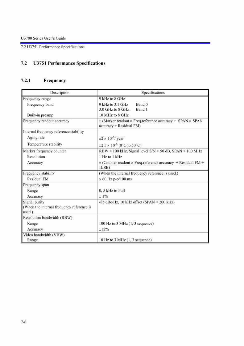
U3700 Series User’s Guide
7.2 U3751 Performance Specifications
7-6
7.2 U3751 Performance Specifications
7.2.1 Frequency
Description SpecificationsFrequency range 9 kHz to 8 GHz
Frequency band 9 kHz to 3.1 GHz Band 03.0 GHz to 8 GHz Band 1
Built-in preamp 10 MHz to 8 GHzFrequency readout accuracy (Marker readout Freq.reference accuracy + SPAN SPAN
accuracy + Residual FM)Internal frequency reference stability
Aging rate 2 10-6/ yearTemperature stability 2.5 10-6 (0C to 50C)
Marker frequency counter RBW < 100 kHz, Signal level S/N > 50 dB, SPAN < 100 MHzResolution 1 Hz to 1 kHzAccuracy (Counter readout Freq.reference accuracy + Residual FM +
1LSB)Frequency stability (When the internal frequency reference is used.)
Residual FM 60 Hz p-p/100 msFrequency span
Range 0, 5 kHz to FullAccuracy 1%
Signal purity(When the internal frequency reference is used.)
-85 dBc/Hz, 10 kHz offset (SPAN < 200 kHz)
Resolution bandwidth (RBW)Range 100 Hz to 3 MHz (1, 3 sequence)Accuracy 12%
Video bandwidth (VBW)Range 10 Hz to 3 MHz (1, 3 sequence)

U3700 Series User’s Guide
7.2.2 Sweep
7-7
7.2.2 Sweep
7.2.3 Amplitude
Description SpecificationsSweep
Sweep time setting rangeZero span 50 s to 1000 sSpectrum mode 20 ms to 1000 s
Sweep time accuracy 2% (Zero Span)Sweep mode REPEAT, SINGLETrigger function
Trigger source Free run, Video, IF, External
Description SpecificationsAmplitude measurement range +30 dBm to displayed average noise levelMaximum safe input level
Average continuous power +30 dBm (Input attenuator 10 dB) Preamp Off+13 dBm (Input attenuator 10 dB) Preamp On
DC voltage 15 VDCmaxInput attenuator range 0 to 50 dB, 10 dB stepDisplay range 100, 50, 20, 10, 5 dB, LinearScale unit dBm, dBmV, dBV, dBVemf, dBpW, W, VReference level setting range
Log scale -140 dBm to +40 dBmDetector mode Normal, Positive Peak, Negative Peak, Sample, RMS, Video
Average

U3700 Series User’s Guide
7.2.4 Amplitude Accuracy
7-8
7.2.4 Amplitude Accuracy
7.2.5 Dynamic Range
Description SpecificationsCalibration signal accuracy (20 MHz)
Frequency 20 MHzAmplitude -20 dBmAccuracy 0.3 dB
Scale display accuracyLog 0.5 dB/10 dB
0.5 dB/80 dB0.2 dB/1 dB
Total level accuracy (After performing the automatic calibration, Image Suppression Off, Signal level: -10 dBm to -50 dBm, Preamp Off, Input attenu-ator: 10dB, REF = 0 dBm, Temperature 20C to 30C)0.8 dB Frequency range 10 MHz to 3.1 GHz1.0 dB Frequency range 3.1 GHz to 8 GHz1.5 dB Frequency range 9 kHz to 10 MHz
Description SpecificationsDisplayed average noise level Frequency range 10 MHz to 8 GHz
Ref level < -45 dBm RBW = 100 Hz-123 dBm + 2 f (GHz)dB Band 0 Preamp Off-122 dBm + 1 f (GHz)dB Band 1 Preamp Off-138 dBm + 3 f (GHz)dB Band 0 Preamp On-139 dBm + 1.3 f (GHz)dB Band 1 Preamp On
1 dB gain compression Frequency range 10 MHz to 8 GHz> -8 dBm Preamp Off> -25 dBm Preamp On
Second harmonic distortion <-70 dBc (Preamp Off, Mixer input level: -40 dBm, Frequency > 200 MHz)<-75 dBc typ (Preamp Off, Mixer input level: -30 dBm, Frequency > 300 MHz)
Third order intermodulation distortion (TOI) (Frequency range 10 MHz to 8 GHz, Preamp Off, Mixer input level: -20 dBm, Frequency separation: 200 kHz)-50 dBc
Image responses, Multiple responses, and Out-of-band responses
(Image Suppression On)< 60 dBc
Residual responses (Frequency 10 MHz to 8 GHz)< -80 dBm Preamp Off

U3700 Series User’s Guide
7.2.6 Input and Output
7-9
7.2.6 Input and Output
Description SpecificationsRF input
Connector Type-N (f) on the front panelImpedance 50 nomVSWR Input attenuator 10 dB
< 1.7:1 (< 3.0 GHz) < 2.0:1 (> 3.0 GHz)
Calibration signal outputConnector BNC (f) on the front panelImpedance 50 nomFrequency 20 MHzLevel -20 dBm
External trigger inputConnector BNC (f) on the rear panelImpedance 10 k nom, DC couplingTrigger level 0 V to 5 V
Frequency reference inputConnector BNC (f) on the rear panelImpedance 50 nomFrequency [MHz] 1, 1.544, 2.048, 5, 10, 12.8, 13, 13.824, 14.4, 15.36, 15.4, 16.8,
19.2, 19.44, 19.6608, 19.68, 19.8, 20, 26Level 0 dBm to 16 dBm
21.4 MHz IF outputConnector BNC (f) on the rear panelImpedance 50 nomOutput level Approximately mixer input level +10 dB at 20 MHz center fre-
quencyBattery mount
Connector Antonbauer QR mountExternal DC input
Connector XLR-4Voltage range 11 V to 17 V
GPIB IEEE-488 bus connectorUSB-A USB1.1 on the front and rear panelsLAN RJ45 on the rear panel
10/100Base-T, Protocol TCP/IPVideo out VGA (15pin f) on the rear panel

U3700 Series User’s Guide
7.3 U3771/U3772 Performance Specifications
7-10
7.3 U3771/U3772 Performance Specifications
7.3.1 Frequency
Description SpecificationsFrequency range [RF Input 1] 9 kHz to 8 GHz: U3771/U3772
Frequency band 9 kHz to 3.1 GHz: Band 03.0 GHz to 8 GHz: Band 1
Built-in preamp 10 MHz to 8 GHz
Frequency range [RF Input 2] 10 MHz to 31.8 GHz U377110 MHz to 43 GHz U3772
Frequency band 10 MHz to 3.1 GHz Band 0 (N=1)3.0 GHz to 8.0 GHz Band 1 (N=1)7.8 GHz to 14.573 GHz Band 2 (N=2)14.4288 GHz to 28.0 GHz Band 3 (N=4)27.8 GHz to 31.8 GHz Band 4 (N=6) (U3771)27.8 GHz to 43.0 GHz Band 4 (N=6) (U3772)
Frequency readout accuracy (Marker readout Freq.reference accuracy + SPAN SPAN accuracy + Residual FM )
Internal frequency reference stabilityAging rate 2 10-6/ yearTemperature stability 2.5 10-6 (0C to 50C)
Marker frequency counter RBW < 100 kHz, Signal level S/N > 50 dB, SPAN < 100 MHzResolution 1 Hz to 1 kHzAccuracy (Counter readout Freq.reference accuracy + Residual FM +
1LSB )Frequency stability (When the internal frequency reference is used.)
Residual FM 60 Hz *N p-p/100 msFrequency span
Range 0, 5 kHz to FullAccuracy 1%
Signal purity(When the internal frequency reference is used.)
(-85 + 20logN) dBc/Hz, 10 kHz offset (SPAN < 200 kHz)
Resolution bandwidth (RBW)Range 100 Hz to 3 MHz (1, 3 sequence)Accuracy 12%
Video bandwidth (VBW)Range 10 Hz to 3 MHz (1, 3 sequence)
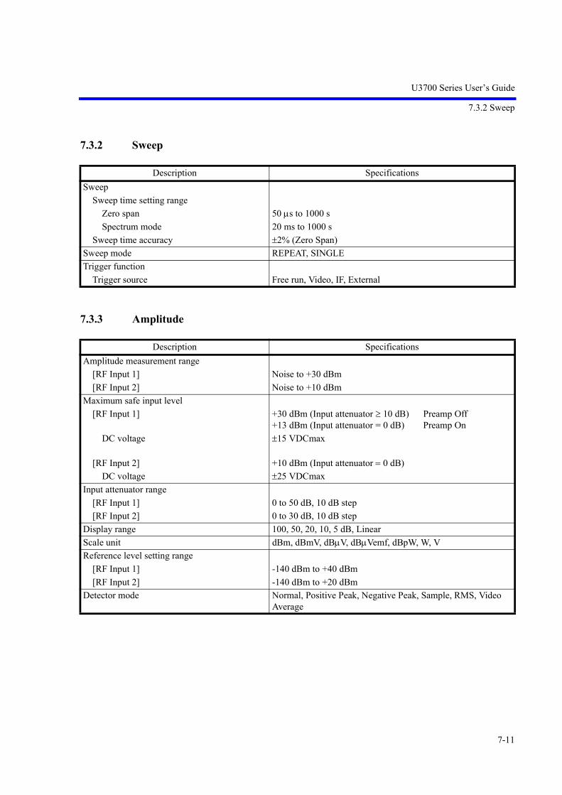
U3700 Series User’s Guide
7.3.2 Sweep
7-11
7.3.2 Sweep
7.3.3 Amplitude
Description SpecificationsSweep
Sweep time setting rangeZero span 50 s to 1000 sSpectrum mode 20 ms to 1000 s
Sweep time accuracy 2% (Zero Span)Sweep mode REPEAT, SINGLETrigger function
Trigger source Free run, Video, IF, External
Description SpecificationsAmplitude measurement range
[RF Input 1] Noise to +30 dBm[RF Input 2] Noise to +10 dBm
Maximum safe input level[RF Input 1] +30 dBm (Input attenuator 10 dB) Preamp Off
+13 dBm (Input attenuator = 0 dB) Preamp OnDC voltage 15 VDCmax
[RF Input 2] +10 dBm (Input attenuator 0 dB)DC voltage 25 VDCmax
Input attenuator range[RF Input 1] 0 to 50 dB, 10 dB step[RF Input 2] 0 to 30 dB, 10 dB step
Display range 100, 50, 20, 10, 5 dB, LinearScale unit dBm, dBmV, dBV, dBVemf, dBpW, W, VReference level setting range
[RF Input 1] -140 dBm to +40 dBm[RF Input 2] -140 dBm to +20 dBm
Detector mode Normal, Positive Peak, Negative Peak, Sample, RMS, Video Average

U3700 Series User’s Guide
7.3.4 Amplitude Accuracy
7-12
7.3.4 Amplitude Accuracy
Description SpecificationsCalibration signal accuracy (20 MHz)
Frequency 20 MHzAmplitude -20 dBmAccuracy 0.3 dB
Scale display accuracyLog 0.5 dB/10 dB
0.5 dB/80 dB0.2 dB/1 dB
Total level accuracy (After performing the automatic calibration, Image Suppression Off, Signal level: -10 dBm to -50 dBm, Preamp Off, Input attenu-ator: 10 dB, REF = 0 dBm, Temperature 20C to 30C)
[RF Input 1] 0.8 dB (Band 0) Frequency 10 MHz to 3.1 GHz1 dB (Band 1) Frequency 3.1 GHz to 8 GHz1.5 dB Frequency 9 kHz to 10 MHz
[RF Input 2] 0.8 dB (Band 0) Frequency 10 MHz to 3.1 GHz1 dB (Band 1) Frequency 3.1 GHz to 8 GHz3.0 dB (Band 2) Frequency 7.8 GHz to 14.573 GHz3.5 dB (Band 3) Frequency 14.4288 GHz to 28.0 GHz4.5 dB (Band 4) Frequency 27.8 GHz to 31.8 GHz (U3771)4.5 dB (Band 4) Frequency 27.8 GHz to 43 GHz (U3772)

U3700 Series User’s Guide
7.3.5 Dynamic Range
7-13
7.3.5 Dynamic Range
Description SpecificationsDisplayed average noise level Frequency range > 10 MHz
Ref level < -45 dBm RBW = 100 Hz
[RF Input 1] -123 dBm + 2 f (GHz)dB Band 0 Preamplifier Off-122 dBm + 1.2 f (GHz)dB Band 1 Preamplifier Off-138 dBm + 3 f (GHz)dB(TBD) Band 0 Preamplifier On-139 dBm + 1.4 f (GHz)dB Band 1 Preamplifier On
[RF Input 2] -121 dBm + 2 f (GHz)dB Band 0-120 dBm + 1.5 f (GHz)dB Band 1-111 dBm (-118 dBm typ.) Band 2-109 dBm (-117 dBm typ.) Band 3-105 dBm (-112 dBm typ.) Band 4
1 dB gain compression Frequency range > 10 MHz> -8 dBm Preamp Off> -25 dBm Preamp On
Second harmonic distortion Preamp Off[RF Input 1] -70 dBc Mixer input level: -40 dBm, Frequency > 200 MHz
<-75 dBc typ Mixer input level: -30 dBm, Frequency > 300 MHz[RF Input 2] -40 dBc Mixer input level: -30 dBm,
Frequency 300 MHz ~ 31.8 GHz (U3771)300 MHz ~ 40 GHz (U3772)
Third order intermodulation distortion (TOI) (Frequency range > 10 MHz, Preamp Off, Mixer input level: -20 dBm, 2-Signal separation:1 MHz)-50 dBc
Image responses, Multiple responses, and Out-of-band responses
(Image Suppression On, Span < 5 GHz)< 60 dBc
Residual responses (Frequency range > 10 MHz)-80 dBm Preamp Off

U3700 Series User’s Guide
7.3.6 Input and Output
7-14
7.3.6 Input and Output
Description SpecificationsRF input 1
Connector Type-N (f) on the front panelImpedance 50 nomVSWR < 1.7:1 (< 3.0 GHz) Band 0 Input attenuator 10 dB
< 2.0:1 (> 3.0 GHz) Band 1 Input attenuator 10 dBRF input 2
Connector Type-K (f) on the front panelImpedance 50 (nom.)VSWR 1.7 : 1 (typ.) Band 0 Input attenuator 10 dB
2.0 : 1 (typ.) Band 1, Band 2, Band 3, Input attenuator 10 dB2.5 : 1 (typ.) Band 4 Input attenuator 10 dB
Calibration signal outputConnector BNC (f) on the front panelImpedance 50 nomFrequency 20 MHzLevel -20 dBm
External trigger inputConnector BNC (f) on the rear panelImpedance 10 k nom, DC couplingTrigger level 0 V to 5 V
Frequency reference inputConnector BNC (f) on the rear panelImpedance 50 nomFrequency [MHz] 1, 1.544, 2.048, 5, 10, 12.8, 13, 13.824, 14.4, 15.36, 15.4, 16.8,
19.2, 19.44, 19.6608, 19.68, 19.8, 20, 26Amplitude 0 dBm to 16 dBm
21.4 MHz IF outputConnector BNC (f) on the rear panelImpedance 50 nomOutput level Approximately mixer input level +10 dB at 20 MHz center fre-
quencyBattery mount
Connector Antonbauer QR mountExternal DC input
Connector XLR-4Voltage range 11 V to 17 V
GPIB IEEE-488 bus connectorUSB-A USB1.1 on the front and rear panelsLAN RJ45 on the rear panel
10/100Base-T, Protocol TCP/IPVideo out VGA (15pin f) on the rear panel

U3700 Series User’s Guide
7.4 General Specifications
7-15
7.4 General Specifications
Description SpecificationsOperation environment Ambient temperature: 0C to +50C
Relative humidity: 85% or less (no condensation)Storage environmental range Ambient temperature: -20C to +60C
Relative humidity: 85% or less (no condensation)AC Power supply input AC100 V to 120 V, 50 Hz/60 Hz
AC220 V to 240 V, 50 Hz/60 Hz(Automatically switches the input voltage between 100 V AC and 220 V AC.)
DC Power input DC +11 V to +17 VPower consumption 100 VA or less For the AC power supply
70 W or less For the DC power supplyDimensions Approximately 308 mm (W) 175 mm (H) 209 mm (D)
Approximately 337 mm (W) 190 mm (H) 307 mm (D) (Including the handle and feet)
Mass Approximately 5.0 kg or less (without option) U3741Approximately 5.6 kg or less (without option) U3751Approximately 6 kg or less (without option) U3771/U3772

U3700 Series User’s Guide
7.5 Options
7-16
7.5 Options
7.5.1 Option 10 2-Channel Input
• Differences from U3741/U3751 input output standard specifications
• Differences from U3771/U3772 standard specifications
Item DescriptionFrequency Conforms to the U3741 standard specifications.
Applied to RF INPUT2 (channel 2)SweepAmplitude rangeAmplitude accuracyDynamic range
Item DescriptionCrosstalk between input channels < -90 dBc (Input level -10 dBm, Input attenuator 0 dB)RF input 2
Connector N type femaleImpedance 50 (nom.)VSWR <1.5 : 1 Input attenuator > 10 dB
External trigger input Can be selected as the trigger input of RF input 2 when OPT10 is installed. The input connector is a single line only.
21.4 MHz IF output When OPT10 is installed, it is only the IF output which corresponds to RF input 1.
Item DescriptionFrequency range [RF INPUT 1] 10 MHz - 31.8 GHz (U3771)
10 MHz - 43 GHz (U3772)Crosstalk between input channels < -90 dBc (Input level -10 dBm, Input attenuator 0 dB)RF input 1
Connector K type femaleImpedance 50 (nom.)VSWR 1.7 : 1 (typ.) Band 0 Input attenuator 10 dB
2.0 : 1 (typ.) Band 1, Band 2, Band 3 Input attenuator 10 dB2.5 : 1 (typ.) Band 4 Input attenuator 10 dB
RF input 2Connector N type femaleImpedance 50 (nom.)VSWR <1.5 : 1 Input attenuator > 10 dB
External trigger input Can be selected as the trigger input of RF input 2 when OPT10 is installed. The input connector is a single line only.
21.4 MHz IF output When OPT10 is installed, it is only the IF output which corresponds to RF input 1.

U3700 Series User’s Guide
7.5.2 Option 11 75 2-Channel Input (Can be Installed only in the U3741)
7-17
7.5.2 Option 11 75 2-Channel Input (Can be Installed only in the U3741)
• Difference with the standard specifications
Item DescriptionFrequency Conforms to the specifications given when U3741 is equipped with OPT15.SweepAmplitude rangeAmplitude accuracyDynamic range
Item DescriptionCrosstalk between input channels < -90 dBc (Input level -10 dBm, Input attenuator 0 dB)RF input 2
Connector N type femaleImpedance 75 (nom.)VSWR <1.6 : 1 Input attenuator > 10 dB
External trigger input Can be selected as the trigger input of RF input 2 when OPT11 is installed. The input connector is a single line only.
21.4 MHz IF output When OPT11 is installed, it is only the IF output which corresponds to RF input 1.

U3700 Series User’s Guide
7.5.3 Option 15 75 Input
7-18
7.5.3 Option 15 75 Input
• Frequency
• Amplitude
• Amplitude Accuracy
Description SpecificationsFrequency range 9 kHz to 2.2 GHz
Built-in preamp 10 MHz to 2.2 GHzTunable frequency 9 kHz to 3 GHz
Description SpecificationsAmplitude measurement range +134 dBV to displayed average noise levelMaximum safe input level Input attenuator 10 dB
Average continuous power +134 dBV Preamp Off+120 dBV Preamp On
DC voltage 50 VDCmaxInput attenuator range 0 to 50 dB, 10 dB stepDisplay range 100, 50, 20, 10, 5 dB, LinearScale unit dBm, dBmV, dBV, dBVemf, dBpW, W, VReference level setting range
Log scale -31.2 dBV to +148.8 dBVDetector mode Normal, Positive Peak, Negative Peak, Sample, RMS, Video
Average
Description SpecificationsCalibration signal accuracy (20 MHz)
Frequency 20 MHzAmplitude -20 dBmAccuracy 0.4 dB
Scale display accuracyLog 0.5 dB/10 dB
0.5 dB/80 dB0.2 dB/1 dB
Total level accuracy (After performing the automatic calibration, Signal level: +98.8 dBV to +58.8 dBV, Preamp Off, Input attenuator: 10 dB, REF = +108.8 dBV, Temperature +20C to +30C)0.9 dB Frequency range 10 MHz to 2.2 GHz2.1 dB Frequency range 9 kHz to 2.2 GHz

U3700 Series User’s Guide
7.5.4 Option 20 High Stability Frequency Reference
7-19
• Dynamic Range
• Input and Output
7.5.4 Option 20 High Stability Frequency Reference
Description SpecificationsDisplayed average noise level Ref level < +63.8 dBV RBW = 100 Hz
-12 dBV + 2 f (GHz)dB Preamp Off-27 dBV + 3 f (GHz)dB Preamp On
1 dB gain compression Frequency range > 20 MHz> +102 dBV Preamp Off> +82 dBV Preamp On
Second garmonic distortion < -70 dBc (Preamp Off, Mixer input level: +77 dBV, Frequency > 20 MHz)
Third order intermodulation distortion (TOI) (Frequency range > 10 MHz, Preamp Off, Mixer input level: +88.8 dBV, Frequency separation: 200 kHz)< -60 dBc
Image responses, Multiple responses, and Out-of-band responses
< -60 dBc, Mixer input level: +88.8 dBV
Residual responses (Frequency > 1 MHz, Preamp Off)< +21 dBV
Description SpecificationsRF input
Connector Type-N (f) on the front panelImpedance 75 nomVSWR Input attenuator 10 dB
< 1.6:1Calibration signal output
Connector BNC (f) on the front panelImpedance 75 nom.Frequency 20 MHzLevel -20 dBm
Description SpecificationsReference frequency stability
Aging rate 2 10-8/ day, 1 10-7/ yearWarm-up drift (nominal) 5 10-8 (+25C, 10 minutes after turning the power on)Temperature drift 5 10-8 (0 to +40C, with reference to +25C)

U3700 Series User’s Guide
7.5.5 Option 28 EMC Filter
7-20
7.5.5 Option 28 EMC Filter
7.5.6 Option 53 Time Domain AnalysisOption 54 2-Channel Time Domain Analysis
• Time domain waveform capture
Description Specifications6 dB bandwidth
Range 200 Hz, 9 kHz, 120 kHz, 1 MHzAccuracy < ±10%
Detector mode Normal, Positive peak, Negative peak, Sample, RMS, Video aver-age, QP
Item Description
RF frequency range Conforms to the frequency range for each model of the U3700 series.
RF amplitude range Noise level to +30 dBm (*1)
Waveform capture format I/Q vector time waveform
Measurement bandwidth (BW) 100 Hz to 3 MHz (1 to 3 steps)
I/Q sampling rate 713 Hz (BW 100 Hz) to 21.4 MHz (BW 3 MHz)
I/Q waveform capture time 49 msec (BW 3 MHz) to 1000 sec (BW 100 Hz)
Number of I/Q waveform capture samples 1M Samples (I/Q)
(*1) The noise level conforms to the dynamic range specifications for each model of the U3700 series.

U3700 Series User’s Guide
7.5.7 Option 55 Wide Band Time Domain Analysis Option 56 2-Channel Wide Band Time Domain Analysis
7-21
7.5.7 Option 55 Wide Band Time Domain AnalysisOption 56 2-Channel Wide Band Time Domain Analysis
• Time domain waveform capture
7.5.8 Option 70 High C/NOption 71 2-Channel High C/N
1. U3741
• Frequency
• Dynamic Range
Item Description
RF frequency range Conforms to the frequency range for each model of the U3700 series.
RF amplitude range Noise level to +30 dBm (*1)
Waveform capture format I/Q vector time waveform
Measurement bandwidth (BW) 100 Hz to 30 MHz (1 to 3 steps), 40 MHz
I/Q sampling rate 500 Hz (BW 100 Hz) to 65 MHz (BW 40 MHz)
I/Q waveform capture time 120 msec (BW 40 MHz) to 1000 sec (BW 100 Hz)
Number of I/Q waveform capture samples 8 M Samples (I/Q)
(*1) The noise level conforms to the dynamic range specifications for each model of the U3700 series.
Description SpecificationsFrequency span
Range 0, 1 kHz to FullAccuracy 1%
Signal purity(When the internal frequency reference is used.)
-98 dBc/Hz, 10 kHz offset (SPAN < 1 MHz)
Resolution bandwidth (RBW)Range 30 Hz to 1 MHz (1, 3 sequence)Accuracy 12%
Description SpecificationsDisplayed average noise level Frequency range > 10 MHz, Ref level < -45, dBm RBW = 30 Hz
-126 dBm + 2 f (GHz)dB f < 2.5 GHz Preamp Off-126 dBm + 2.5 f (GHz)dB f 2.5 GHz Preamp Off-141 dBm + 3 f (GHz)dB Preamp On

U3700 Series User’s Guide
7.5.8 Option 70 High C/N Option 71 2-Channel High C/N
7-22
2. U3751
• Frequency
• Dynamic Range
3. U3771/U3772
• Frequency
Description SpecificationsFrequency span
Range 0, 1 kHz to FullAccuracy 1%
Signal purity(When the internal frequency reference is used.)
-98 dBc/Hz, 10 kHz offset (SPAN < 1 MHz)
Resolution bandwidth (RBW)Range 30 Hz to 3 MHz (1, 3 sequence)Accuracy 12%
Description SpecificationsDisplayed average noise level Frequency range > 10 MHz
Ref level < -45 dBm RBW = 30 Hz-126 dBm + 2 f (GHz)dB Band 0 Preamp Off-125 dBm + 1 f (GHz)dB Band 1 Preamp Off-141 dBm + 3 f (GHz)dB Band 0 Preamp On-142 dBm + 1.3 f (GHz)dB Band 1 Preamp On
Description SpecificationsFrequency span
Range 0, 1 kHz to FullAccuracy 1%
Signal purity(When the internal frequency reference is used.)
(-98 + 20logN) dBc/Hz, 10 kHz offset (SPAN < 1 MHz)
Resolution bandwidth (RBW)Range 30 Hz to 3 MHz (1, 3 sequence)Accuracy 12%

U3700 Series User’s Guide
7.5.9 Option 75 75 Tracking Generator
7-23
• Dynamic Range
7.5.9 Option 75 75 Tracking Generator
Description SpecificationsDisplayed average noise level Frequency range > 10 MHz
Ref level < -45 dBm RBW = 30 Hz
[RF Input 1] -126 dBm + 2 f (GHz)dB Band 0 Preamplifier Off-125 dBm + 1.2 f (GHz)dB Band 1 Preamplifier Off-141 dBm + 3 f (GHz)dB(TBD) Band 0 Preamplifier On-142 dBm + 1.4 f (GHz)dB Band 1 Preamplifier On
[RF Input 2] -124 dBm + 2 f (GHz)dB Band 0-123 dBm + 1.5 f (GHz)dB Band 1-114 dBm Band 2-112 dBm Band 3-108 dBm Band 4
Description SpecificationsFrequency range 100 kHz to 2.2 GHzFrequency offset
Range 0 to 1 GHzResolution 1 kHzAccuracy 300 Hz
Output level range +107 to +47 dBV 0.5 dB stepOutput level accuracy 0.5 dB 20 MHz, +97 dBV, +20C to +30COutput level flatness Reference signal level: +97 dBV, Frequency: 20 MHz
1.0 dB (1 MHz to 1 GHz)1.5 dB (100 kHz to 2.2 GHz)
Output level switching uncertainty Reference level: +97 dBV1.0 dB (1 MHz to 1 GHz) +107 to +47 dBV2.0 dB (1 MHz to 2.2 GHz) +107 to +47 dBV3.0 dB (100 kHz to 2.2 GHz)+107 to +77 dBV Frequency Offset OFF4.0 dB (100 kHz to 2.2 GHz)+77 to +47 dBV Frequency Offset OFF5.0 dB (100 kHz to 2.2 GHz)+107 to +47 dBV Frequency Offset ON
Spurious output Output level: +97 dBVHarmonics -15 dBc (100 kHz to 1 MHz)
-20 dBc (1 MHz to 2.2 GHz)Non-harmonics -20 dBc Frequency Offset OFF
TG leakage +39 dBV Input attenuator: 0 dBOutput impedance 75 (nom.)
VSWR 2 (typ.) Output level +97 dBVMaximum allowable input +117 dBV, 10 V

U3700 Series User’s Guide
7.5.10 Option 76 Tracking Generator
7-24
7.5.10 Option 76 Tracking Generator
Description SpecificationsFrequency range 100 kHz to 3 GHzFrequency offset
Range 0 to 1 GHzResolution 1 kHzAccuracy 300 Hz
Output level range 0 to -60 dBm 0.5 dB stepOutput level accuracy 0.5 dB 20 MHz, -10 dBm, +20C to +30COutput level flatness Reference signal level: -10 dBm, Frequency: 20 MHz
1.0 dB (1 MHz to 1 GHz)1.5 dB (100 kHz to 3 GHz)
Output level switching uncertainty Reference level: -10 dBm1.0 dB (1 MHz to 1 GHz) 0 to -60 dBm2.0 dB (1 MHz to 2.6 GHz) 0 to -60 dBm3.0 dB (100 kHz to 3 GHz) 0 to -30 dBm Frequency Offset OFF4.0 dB (100 kHz to 3 GHz) -30.5 to -60 dBm Frequency Offset OFF5.0 dB (100 kHz to 3 GHz) 0 to -60 dBm Frequency Offset ON
Spurious output Output level: -10 dBmHarmonics -15 dBc (100 kHz to 1 MHz)
-20 dBc (1 MHz to 3 GHz)Non-harmonics -20 dBc Frequency Offset OFF
TG leakage -80 dBm Input attenuator: 0 dBOutput impedance 50 (nom.)
VSWR 2 (typ.) Output level -10 dBmMaximum allowable input 10 dBm, 10 V
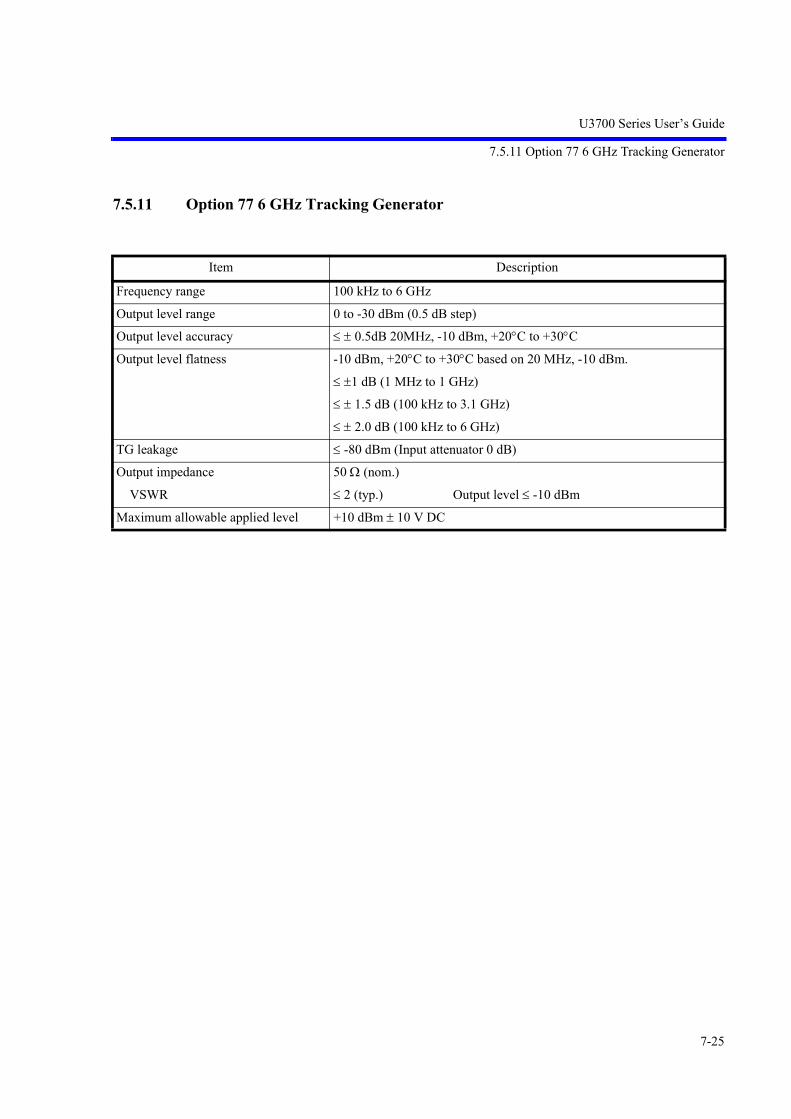
U3700 Series User’s Guide
7.5.11 Option 77 6 GHz Tracking Generator
7-25
7.5.11 Option 77 6 GHz Tracking Generator
Item Description
Frequency range 100 kHz to 6 GHz
Output level range 0 to -30 dBm (0.5 dB step)
Output level accuracy 0.5dB 20MHz, -10 dBm, +20C to +30C
Output level flatness -10 dBm, +20C to +30C based on 20 MHz, -10 dBm.
1 dB (1 MHz to 1 GHz)
1.5 dB (100 kHz to 3.1 GHz)
2.0 dB (100 kHz to 6 GHz)
TG leakage -80 dBm (Input attenuator 0 dB)
Output impedance 50 (nom.)
VSWR 2 (typ.) Output level -10 dBm
Maximum allowable applied level +10 dBm 10 V DC


U3700 Series User’s Guide
8. OPTIONS AND ACCESSORIES
8-1
8. OPTIONS AND ACCESSORIES
This chapter describes the options and accessories for this instrument.
8.1 Options
Table 8-1 Options
Option Description Note
OPT10 2-channel input option
OPT11 2-channel input option 75 For U3741 only
OPT15 75 input For U3741 only
OPT20 High stability frequency reference
OPT28 EMC filter
OPT53 Time domain analysis option
OPT54 2-channel time domain analysis option
OPT55 Wide Band time domain analysis option
OPT56 2-channel Wide Band time domain analysis option
OPT70 High C/N
OPT71 2-channel High C/N
OPT75 Tracking generator 75 For U3741 only
OPT76 Tracking generator
OPT77 6 GHz tracking generator U3751, U3771, and U3772
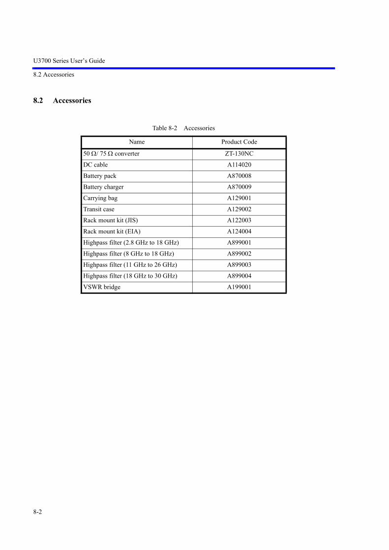
U3700 Series User’s Guide
8.2 Accessories
8-2
8.2 Accessories
Table 8-2 Accessories
Name Product Code
50 / 75 converter ZT-130NC
DC cable A114020
Battery pack A870008
Battery charger A870009
Carrying bag A129001
Transit case A129002
Rack mount kit (JIS) A122003
Rack mount kit (EIA) A124004
Highpass filter (2.8 GHz to 18 GHz) A899001
Highpass filter (8 GHz to 18 GHz) A899002
Highpass filter (11 GHz to 26 GHz) A899003
Highpass filter (18 GHz to 30 GHz) A899004
VSWR bridge A199001

U3700 Series User’s Guide
9. MAINTENANCE
9-1
9. MAINTENANCE
This chapter describes the following matters related to the maintenance of this instrument in order to maintainits designed performance.
• 9.1 Cleaning
• 9.2 About Calibration
• 9.3 About Replacement of Limited-Life Parts
• 9.4 Method of Storing the Instrument
• 9.5 Transportation
• 9.6 Notes for Requesting Repair, Replacement of Parts, and Periodic Calibration
• 9.7 List of Error Messages
• 9.8 In Case of Difficulty
• 9.9 Product Disposal and Recycle
9.1 Cleaning
This section describes how to clean this instrument and some matters to note.
WARNING: Turn off the power breaker on the rear panel and extract the power cable from the wall socket to pro-tect yourself from electric shock accidents. Never attempt to remove the cabinet cover to clean the inside of the instrument.
9.1.1 Cabinet Cleaning
Use the following procedure to clean the cabinet of this instrument.
Clean the cabinet surface with a soft dry cloth.If the surface is not clean enough, try again with a cloth soaked in a weakened neutral detergent. Then wipethe surface with a soft dry cloth.
CAUTION: Do not allow water to splash into the inside of the instrument. Do not use an organic solvent such as benzene, toluene, xylene, or acetone and the cleanser forcleaning. They can cause the paint on the cabinet to come off, deform, or degrade.

U3700 Series User’s Guide
9.1.2 Cleaning of Other Parts
9-2
9.1.2 Cleaning of Other Parts
Use appropriate caution to protect this instrument from dust.
WARNING: Remove dust periodically from wall sockets and power connector plugs. Dust that is wet with humidity may cause tracking that could cause a fire. The rear panel is equipped with an exhaust cooling fan and the side and the bottom panels haveexhaust vents. Keep these vents clean for sufficient exhaustion. If dust piled on the vents causesexhaustion to become poor, the temperature inside will rise and the instrument will not work cor-rectly.
9.2 About Calibration
Calibration should be performed periodically to prevent performance deterioration or to adjust chronologicalperformance changes.The recommended period of regular calibration is once a year.
Calibration is done at the factory site. For more information, call a sales representative.
9.3 About Replacement of Limited-Life Parts
Table 9-1 lists the proper limited-life parts of this instrument.The table also shows the number of operations for the expected life spans of each of these parts, to suggest arecommended time of replacement in terms of the number of times of operations. For replacement, call theService Center (Advantest Customer Support (ACS)).
Note that the life span can become shorter than expected depending on the operation environment, frequencyof use, and storage environment.
MEMO: The table shows the expected life spans or recommended time of replacement only for the user's reference.It does not guarantee the life of the components.
Table 9-1 Limited-Life Parts
Name Life (Reference values)Panel key switch
Key switch with LED106 operations105 operations
LCD back light 50,000 hoursRotary encoder 25 106 operationsCooling fan 40,000 hoursLithium battery cells for data backup About 3 yearsMechanical relay (For EXT. DC) 105 operationsMechanical relay (For input attenuator) 106 operationsCoaxial relay (For RF1 or RF2) 106 operations

U3700 Series User’s Guide
9.4 Method of Storing the Instrument
9-3
9.4 Method of Storing the Instrument
When you store this instrument, keep it in an environment that meets the following requirements.
• Reduced vibration
• Not dusty
• Protected from direct sunlight
• Ambient temperature range: -20C to +60C
• Relative humidity: 30% to 85%
When you do not use the instrument for 90 days or more, store it in an appropriate moisture-proof bag withdesiccant.
9.5 Transportation
For transportation, use the packing materials used for the shipping of this instrument. If you use othermaterials, pack the instrument using the following procedure.
1. Install the protection cover of the touch screen display on this instrument.
2. Cover the instrument with a protective plastic sheet. (Put desiccant inside for protection from mois-ture.)
3. Prepare a carton case. The panels of the case must be 5 mm or more thick. The inner dimensions must be 10 cm or morelarger than the physical size of this instrument because cushioning materials are placed inside. Place the instrument so that it is covered with cushioning or plastic foam material on all sides. (Thecushioning material must be 4 cm or more thick.)
4. Seal the carton case with an industrial stapler or packing tape.
9.6 Notes for Requesting Repair, Replacement of Parts, and Periodic Calibration
9.6.1 Work Request
Attach a tag indicating the following data to this instrument when you send it to a sales representative.
• Your company name and address
• Name of the person in charge
• Serial number (on the rear panel)
• What work to request (repair or periodic calibration)
9.6.2 Destination and Phone Number for Contact
Call Advantest MS (Measuring Instruments) Call Center.
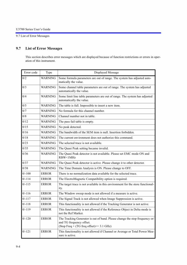
U3700 Series User’s Guide
9.7 List of Error Messages
9-4
9.7 List of Error Messages
This section describes error messages which are displayed because of function restrictions or errors in oper-ation of this instrument.
Error code Type Displayed Message
0/2 WARNING Some formula parameters are out of range. The system has adjusted auto-matically the value.
0/3 WARNING Some channel table parameters are out of range. The system has adjusted automatically the value.
0/4 WARNING Some limit line table parameters are out of range. The system has adjusted automatically the value.
0/5 WARNING The table is full. Impossible to insert a new item.
0/7 WARNING No formula for this channel number.
0/8 WARNING Channel number not in table.
0/12 WARNING The pass fail table is empty.
0/15 WARNING No peak detected.
0/16 WARNING The bandwidth of the SEM item is null. Insertion forbidden.
0/18 WARNING The current environment does not authorize this command.
0/23 WARNING The selected trace is not available.
0/35 WARNING The Quasi Peak setting became invalid.
0/36 WARNING The Quasi Peak detector is not available. Please set EMC mode ON and RBW<1MHz
0/37 WARNING The Quasi Peak detector is active. Please change it to other detector.
0/38 WARNING The Time Domain Analysis is ON. Please change to OFF.
0/-100 ERROR There is no normalization data available for the selected trace.
0/-114 ERROR The ElectroMagnetic Compatibility option is required.
0/-115 ERROR The target trace is not available in this environment for the store functional-ity.
0/-116 ERROR The Window sweep mode is not allowed if a measure is active.
0/-117 ERROR The Signal Track is not allowed when Image Suppression is active.
0/-118 ERROR This functionality is not allowed if the Tracking Generator is not active.
0/-119 ERROR This functionality is not allowed if the Reference Object in Delta mode is not the Ref Marker.
0/-120 ERROR The Tracking Generator is out of band. Please change the stop frequency or/and TG frequency offset.(Stop Freq + (TG freq offset)<= 3.1 GHz)
0/-121 ERROR This functionality is not allowed if Channel or Average or Total Power Mea-sure is active.

U3700 Series User’s Guide
9.7 List of Error Messages
9-5
0/-122 ERROR The Tracking Generator option is required.
0/-123 ERROR This functionality is not allowed on Spurious Power Measure mode.
0/-124 ERROR All limit Lines are OFF. Please activiate at least one line.
0/-125 ERROR The active measure is not allowed in this context mode. The measure has been switched off.
0/-126 ERROR This functionality is not allowed on Graphical Zoom Mode. Please change the context mode. (Ext Cfg -> Zoom & Context)
0/-127 ERROR This functionality is not allowed on multi-context Mode. Please change the context mode. (Ext Cfg -> Zoom & Context -> Reset Context)
0/-128 ERROR The Frequency Reference INT mode is not available with crystal option.
0/-129 ERROR The crystal option is required.
0/-130 ERROR Not available in Zoom (F/F) mode.
0/-131 ERROR Not available in Zoom (T/T) mode.
0/-132 ERROR Not available in F/T mode (Ext. config).
0/-133 ERROR Not available in T/T mode (Ext. config).
0/-135 ERROR The trace subtract result should be in Write mode. Please change it. (operand1 - operand 2 -> result) (Trace -> Refresh ->Write)
0/-136 ERROR The second operand trace should not be in Blank mode. Please change it. (operand1 - operand 2 -> result)
0/-137 ERROR The first operand trace should not be in Blank mode. Please change it. (operand1 - operand 2 -> result)
0/-138 ERROR The table selected for the spurious measure is empty. Please fill the table.
0/-141 ERROR Impossible to change the Fundamental Frequency . Please change to Funda-mental mode ON. (Meas2 -> Harmonics -> Fundamental)
0/-142 ERROR Impossible to execute recall functionality. The file is not compatible with this FUS version.
0/-145 ERROR The TTL Trigger level is available only in EXTERNAL mode.
0/-146 ERROR The Trigger level is available only in IF or VIDEO mode.
0/-147 ERROR The Trigger slope is not available in FREE RUN mode.
0/-148 ERROR The Trigger video is only available in zero span mode.
0/-149 ERROR The ACP graph mode is ON. Watt and Volt Units is not allowed.
0/-150 ERROR The ACP graph mode is not allowed in multi-context mode.
0/-151 ERROR The Carrier Band Width is not available when Nyquist Filter is ON. Please change to OFF. (Meas 1 -> ACP -> Config -> Nyquist Filter)
0/-152 ERROR The Carrier Band Width is not available in FULL mode screen. Please change to CARR mode. (Meas 1 -> ACP -> Mode)
0/-153 ERROR The ACP Power Measure is executed on Trace A. This trace is actually in blank mode. Please change to Write mode. (Trace -> Refresh ->Write)
Error code Type Displayed Message

U3700 Series User’s Guide
9.7 List of Error Messages
9-6
0/-154 ERROR The ACP Channel definition table is empty.
0/-155 ERROR The Carrier Band Width is not available when Nyquist Filter is ON. Please change to OFF. (Meas 1 -> SEM ->Config ->Nyquist Filter)
0/-157 ERROR The SEM table is empty.
0/-158 ERROR Impossible to insert in the SEM table. Overlapping Band.
0/-159 ERROR Pass Fail functionality not authorized. Spectrum Emission Mask active.
0/-160 ERROR The power measure is performed on a blank trace.
0/-161 ERROR The OBW Power Measure is active.
0/-162 ERROR The Power Measure environment is not valid. Please do ensure you have already save an environment for this Power Measure.
0/-163 ERROR The power measure trace is in blank mode. Please change to Write mode. (Trace -> Refresh -> Write)
0/-166 ERROR Scale is Linear Mode. Please select dB/div scale. (Level -> dB/div)
0/-167 ERROR The target stored trace is the same to the active trace.
0/-168 ERROR Impossible to set all the trace in blank mode.
0/-169 ERROR The active trace is in blank mode.
0/-170 ERROR Noise Measure (dBc/Hz) Impossible to work on the reference marker.
0/-171 ERROR Impossible to work on the reference marker.
0/-172 ERROR The delta mode is disable.
0/-173 ERROR The fixed mode is active.
0/-174 ERROR The active marker is not enable.
0/-175 ERROR There is no enable marker.
0/-178 ERROR Span is not set to 0 Hz. Please change span.
0/-179 ERROR Span is set 0 Hz. Please change span.
0/-180 ERROR Impossible to change the parameter. Please insert data in channel table.
0/-181 ERROR Impossible to change the parameter. Please switch on at least one formula.
0/-182 ERROR Impossible to change the Stop Frequency via normal mode.
0/-183 ERROR Impossible to change the Start Frequency via normal mode.
0/-184 ERROR Impossible to change the Center Frequency via normal mode.
0/-185 ERROR Impossible to change the Stop Frequency via channel mode.
0/-186 ERROR Impossible to change the Start Frequency via channel mode.
0/-187 ERROR Impossible to change the Center Frequency via channel mode.
0/-500 ERROR The Time Domain Analysis option is required.
3/1 ERROR Could not save screen copy.
3/2 ERROR The screen copy cannot be saved on the analyzer memory. Please select another media.
Error code Type Displayed Message

U3700 Series User’s Guide
9.7 List of Error Messages
9-7
3/3 ERROR Cannot remove protected file : %1
3/4 ERROR Cannot rename protected file : %1
3/5 ERROR Cannot replace protected file : %1
3/6 ERROR Cannot open file : %1
3/7 ERROR File %1 Unknown data format.
3/8 ERROR File %1 Corrupted Data.
3/9 ERROR File %1 Incompatible Version.
3/10 ERROR Cannot access media.
3/11 ERROR File not saved. Not enough space on media.
3/12 ERROR XML files cannot be saved on the analyzer memory. Please select another media.
3/13 ERROR Cannot create file.
3/14 ERROR Format media failed.
3/15 ERROR No printer detected.
3/16 ERROR No driver available for this printer.
3/17 WARNING The last power measure mode has been turned off.
3/18 WARNING The selected button already exist.
3/19 WARNING The user menu is full.
3/20 WARNING Incorrect password.
3/21 WARNING Quit spurious results before.
3/22 WARNING Quit table edition before.
3/24 WARNING Cannot format flash memory.
3/25 WARNING The tracking generator option is required.
3/26 WARNING No DHCP server found. Please ensure ethernet cable is connected and ver-ify DHCP server configuration.
5/-87 WARNING NO PEAK FOUND.
5/-88 WARNING NO MIN PEAK FOUND.
5/-89 WARNING NO PEAK FOUND.
5/-90 WARNING IM : NO PEAK FOUND.
5/-92 WARNING Parameter out of range : Nyquist data must be changed.
5/-93 WARNING Integration bandwidth out of range.
5/-94 WARNING Parameter out of range.
5/-95 WARNING Parameter out of range : the SPAN must be reduced.
5/-96 WARNING The Channel table is empty.
5/-97 WARNING ACP parameter out of range.
Error code Type Displayed Message

U3700 Series User’s Guide
9.7 List of Error Messages
9-8
CAUTION:
An error may be displayed because of a hardware failure. In this case, contact Advantest.
1. An error that occurred when the calibration was performed
2. An error that was detected while the self test was performed
3. Others
5/-98 WARNING Parameter out of range. Please set the span to a value greater than (1+B)1/T.
5/-99 WARNING Parameter out of range. Please change span.
5/-100 WARNING Parameter out of range.
7/83 WARNING Frequency Reference Unlocked
Error code Type Displayed Message

U3700 Series User’s Guide
9.8 In Case of Difficulty
9-9
9.8 In Case of Difficulty
Check the following basics before calling Advantest.
No. Description Operation
1 "Warning 7/83 Frequency Reference Unlocked" is displayed.
Is the Frequency Reference set to EXT? SYSTEM , Frequency Reference,
1. Set it to INT. INT
2. If EXT is used as the Frequency Reference:Is a frequency reference signal input to the REF IN con-nector on the rear panel?
Is the input reference frequency equal to the reference frequency set in this instrument?
Ref Freq
2 After the power is turned on, the system does not boot up.
Is a USB memory key inserted?Remove the USB memory key and then turn the power on again.
3 Any key input cannot be accepted.
Is the key lock set to ON? (Is the LOCK key lamp illuminated?).
Set the key lock to OFF. LOCK, (password x,x,x,x,) Hz, HzTurning off and on the power is also recommended.
4 If you do not remember the User Password:
Perform the Initialization by using the GPIB. The User Pass-word returns to "0,0,0,0".
Command "RPWD"
5 The USB memory key is not recognized.
1. Check its format.If formatting the USB memory key on a PC, use the FAT format.Some formats such as NTFS are not recognized.
2. The USB memory key with a security function cannot be used.
3. A USB port is located on the front and rear panels.Attempt to change the USB memory key to a different port.
6 An incorrect measured value, which is approx. 6 dB higher than the correct level, is displayed.
Is the Input Impedance set to 75 ?Set it to 50 .
AMPLITUDE, Input Impedance (50)

U3700 Series User’s Guide
9.9 Product Disposal and Recycle
9-10
9.9 Product Disposal and Recycle
This product should be disposed of according to the regulations and laws that are established in your countryand municipality.
Before this product is disposed of, separately collect components shown in the table below to prevent thespread of substances, which may be harmful to the global environment, humans, and ecology.
Substance/Component Used/Not used Location Parts and material
Polychlorinated biphenyls (PCB) con-taining capacitors
Not used - -
Mercury containing components Used LCD monitor Fluorescent tube
Batteries Used BPG-032411BPL-035851
Lithium-ion battery
Printed circuit boards Used Panel Printed circuit board
Power supply
Board
Toner cartridges Not used - -
Plastic containing brominated flame retardants
Used WBL-FUS#FRONT*EBEB-032400BEG-032413BEG-032415BPG-032410BPG-032411BPL-035851BPG-032412BPB-032890BPG-032405BPG-032409BPG-033493BPG-034304BPG-034495BPG-034498BEG-036043BPG-036392
Connectors, inductors, tantalum capacitors, diodes, transistors, semiconductor packages
Asbestos waste and components which contain asbestos
Not used - -
Cathode ray tubes Not used - -
Chlorofluorocarbons (CFC), Hydro-chlorofluorocarbons (HCFC), Hydrof-luorocarbons (HFC) or Hydrocarbons (HC)
Not used - -
Gas discharge lamps Used LCD monitor Fluorescent tube

U3700 Series User’s Guide
9.9 Product Disposal and Recycle
9-11
Liquid crystal displays of a surface greater than 100 square centimeters and all those back-lighted with gas discharge lamps
Used LCD monitor Liquid crystal displays
External electric cables Used WBL-U3751*FWBL-U377X#F
Power cable
WBL-U3751*FWBL-U377X#F
Signal cable
Components containing refractory ceramic fibers
Not used - -
Components containing radioactive substances
Not used - -
Electrolyte capacitors containing sub-stances of concern (height > 25 mm, diameter > 25 mm or proportionately similar volume)
Not used - -
Cadmium and Cadmium compounds Used BPC-032551 Variable resistor electric contact
Antimony and Antimony compounds Used WBL-FUS#FRONT*EBEB-032400BEG-032413BEG-032415BPG-032410BPG-032411BPL-035851BPG-032412BPB-032890BPC-032551BPG-032405BPG-032409BPG-033493BPG-034304BPG-034495BPG-034498BEG-036043BPG-036392A199001 (Accessory)
Electronic components (Semicon-ductors, capacitors, inductors, resis-tors), electric components (Connectors)
Substance/Component Used/Not used Location Parts and material

U3700 Series User’s Guide
9.9 Product Disposal and Recycle
9-12
Beryllium and Beryllium compounds Used WBL-FUS#COXCBLWBL-U3751*FWBL-U377X#FWBL-FUS#HONTAI*EWHB-THK700BEG-032413BPG-033493BPG-034495BPG-036392
Electric components (Switches, connectors)
Arsenic and Arsenic compounds Used WBL-FUS#FRONT*EWHB-THK700BEG-032413BEG-036043BPL-035851
Module (Inverter), electronic com-ponents (GaAs)
Lead and Lead compounds Used WBL-FUS#FRONT*EWBL-FUS#COXCBLWBL-FUS#OPT20WBL-FUS#FRONT*EWBL-FUS#HONTAI*EBEB-032400BEG-032413BEG-032415BPG-032410BPG-032411BPL-035851BPG-032412BPB-032890BPC-032551BPG-032405BPG-032409BPG-033493BPG-034304BPG-034495BPG-034498BEG-036043BPG-036392A199001 (Accessory)
Electronic components mounted on the printed circuit board and lead solder used for mounting.
Vinyl chloride (PVC) Used WBL-FUS#COXCBLWBL-FUS#OPT20WBL-FUS#FRONT*E
PVC-material resin parts
Substance/Component Used/Not used Location Parts and material

U3700 Series User’s Guide
APPENDIX
A-1
APPENDIX
A.1 Initial Setting List
This section describes the default preset parameter setting list.
Values are set for the RF1 input of the U3751, U3771, and U3772. Values in parenthesis are set for the U3741.
Function Parameter Initial set value
FREQUENCY Center Freq setting 4 GHz (1.5 GHz)
Start Freq setting 0 Hz
Stop Freq setting 8 GHz (3 GHz)
Freq Offset setting 0 Hz
Freq Offset ON/OFF Off
CF Step Size setting (Manual) 0.8 GHz (0.3 GHz)
CF Step Size (Auto/Manual) Auto
Channel Input OFF
SPAN Span setting 8 GHz
AMPLITUDE Ref Level setting 0 dBm
LOG/LIN selection LOG
dB/div setting 10 dB/div
Unit setting dBm
ATT (Auto/Manual) Auto
ATT setting (Manual) 10 dB
Min ATT setting 10 dB
Min ATT ON/OFF OFF
High Sensitivity ON/OFF OFF
Ref Offset setting 0.00 dB
Ref Offset ON/OFF OFF
Slide Screen OFF
CPL RBW setting (Manual) 3 MHz (1 MHz)
RBW (Auto/Manual) Auto
VBW setting (Manual) 3 MHz (1 MHz)
VBW (ON/OFF) OFF
VBW/RBW ratio 1
VBW/RBW ratio (Auto/Manual) Auto
SPAN/RBW ratio 100

U3700 Series User’s Guide
A.1 Initial Setting List
A-2
SPAN/RBW ratio (ON/OFF) OFF
Sweep Time setting (Manual) 90 ms (60 ms)
Sweep Time (Auto/Manual) Auto
EXT CFG Sweep Mode (SGL/CNT) CNT
Trigger Source Free Run
Limit Lines OFF
Display Line ON/OFF OFF
Reference Line ON/OFF OFF
Measuring Window OFF
MKR OFF
MEAS1
Channel Power Execute ON/OFF OFF
Total Power Execute ON/OFF OFF
Average Power Execute ON/OFF OFF
OBW Execute ON/OFF OFF
ACP Execute ON/OFF OFF
Spectrum Emission Execute ON/OFF OFF
Spurious Execute ON/OFF OFF
MEAS2
Noise/Hz Execute ON/OFF OFF
XdB down XdB setting OFF
Intermod Execute ON/OFF OFF
Harmonic Execute ON/OFF OFF
Frequency Counter Execute ON/OFF OFF
TRACE Refresh Mode setting Write
Active Trace setting A
Trace Detector Normal/Posi/Nega/Sample/Average
Normal
Calc Mode setting Write
Detector (Auto/Manual) Auto
Detector Avg Mode RMS/Video RMS
SYSTEM Annotation ON/OFF ON
GPIB Address 8
LAN IP Address refer to “6.3.2”
Color Pattern Color1
Function Parameter Initial set value

U3700 Series User’s Guide
A.1 Initial Setting List
A-3
.
Function Parameter Initial set value
[GPIB Address] GPIB address of this instrument 8
[Freq Reference] INT/EXT INT
Ext. Reference 10 MHz
[Display] Title setting NULL

U3700 Series User’s Guide
A.2 Principle of Operation
A-4
A.2 Principle of Operation
This section describes a root Nyquist filter used for input saturation and ACP measurement based on the oper-ating principle of this instrument.
A.2.1 Input Saturation
When a large level signal is applied to this instrument, measurement errors may become larger, dependingon the attenuator setting. Input saturation may be suspected as a cause of this. This section describes inputsaturation.
• Cause of Input SaturationA block diagram of the input section of this instrument is shown in Figure A-1. The signal enteringfrom the input connector is input into the mixer through the attenuator.
Figure A-1 Block Diagram of the Input Section
Under normal conditions, the input level and output level of the mixer are proportionate to each other.However, if the input level of the mixer increases, the mixer becomes saturated and the output levelof the mixer is disproportionate to the input level.This phenomena is called input saturation and it prevents accurate measurements from being made(see Figure A-2).
Figure A-2 Relation Between Input and Output of the Mixer
Attenuator Mixer
1st LO oscillator
IF out RF in
1st LO in
Out
put l
evel
IF o
ut
Input level RF in

U3700 Series User’s Guide
A.2.2 Root Nyquist Filter
A-5
• Preventing Input SaturationIf input saturation occurs, set the most suitable attenuator value to lower the mixer input level.
IMPORTANT: If the attenuator setting is too high, the mixer input signal becomes smaller and analysisbecomes impossible. However, if the attenuator setting is too low, the internal mixer circuitmay become damaged.
Usually, the appropriate settings are automatically set for a continuous wave (CW) input signal if youset the attenuator to auto and set the peak of the signal to or below the reference level.If the resolution bandwidth (RBW) is narrower than the modulation bandwidth in the measurementof an input signal with a wide modulation band, the display level decreases. Therefore, the attenuatormust be manually set to the optimum value.
• Confirming that the attenuator is set to the optimum value
1. Obtain a rough set value for the attenuator by using the following formula.The maximum input level of the mixer is -5 dBm.Input attenuator set value (dB) Input level (dBm) + 10 dB
2. Decrease the attenuator setting in steps while watching the screen. If the peak value on the screendoes not change, no input saturation occurs and the measurement can be continued.If the peak value changes, increase the attenuator setting to eliminate the change.
A.2.2 Root Nyquist Filter
When measuring the adjacent channel leakage power, this instrument is able to make a correction to theinput signal equivalent to as if the signal passed through the root Nyquist filter.
When calculating the power for each channel by integrating the trace data, the power is multiplied by thecoefficient of the root Nyquist filter at the corresponding frequency (H(n)).
The coefficient of the root Nyquist filter (H(n)) is calculated from the symbol rate (T) and the roll-off factor() by using the following formula.
P’’U =10 H(n)
P(n)10b
n = a
a =fUch -(1 + )
2T ,b=fUch +
(1 + )2T
P’’L =10 H(n)
P(n)10b
n = a
a =fLch -(1 + )
2T ,b=fLch +
(1 + )2T

U3700 Series User’s Guide
A.2.2 Root Nyquist Filter
A-6
The characteristics of the root Nyquist filter are shown below.
Figure A-3 Characteristics of the Root Nyquist Filter

U3700 Series User’s Guide
A.3 Glossary
A-7
A.3 Glossary
Resolution Bandwidth
The spectrum analyzer uses the band-pass filter (BPF) to analyze certain frequencies in the input signal. The3 dB bandwidth of the BPF is called the resolution bandwidth. (See Figure A-4) The BPF characteristicsshould be set according to the sweep width and the sweep speed used for the trace.This spectrum analyzer sets the optimal value for the sweep width. In general, smaller bandwidths improveresolution and the resolution of the spectrum analyzer should be expressed by using the narrowest resolutionbandwidth (See Figure A-4 (b) below).
Figure A-4 Resolution Bandwidth
IF Gain Uncertainty
The uppermost scale on the screen is the reference used to read the absolute level of an input signal on thespectrum analyzer. The level set for this uppermost scale is referred to as the reference level.The reference level is set using the Ref Level key and displayed in dBm or dB. The absolute accuracy ofthis display is determined by the IF gain uncertainty assuming the input attenuator is at a constant level.
Figure A-5 IF Gain Uncertainty
Gain Compression
If the input signal is greater than a certain value, the correct value is not displayed on the screen, and the inputsignal appears as if it were compressed. This phenomenon is called gain compression, and it reflects the lin-earity in the input signal range. Normally, the gain compression for a spectrum analyzer is specified as theinput signal level that produces a 1 dB error from a perfect linear response.
RBW = resolution bandwidth
Signal spacing
Resolution bandwidth(a)
Resolution(b)
RBW Signal spacing

U3700 Series User’s Guide
A.3 Glossary
A-8
Maximum Input Level
This is the maximum level allowed for the input circuit of the spectrum analyzer. The level can be modifiedby the input attenuator.
Noise Sidebands
Noise sidebands are used to show the purity of the oscillator.Spectrum analyzer efficiency is reduced by noise generated in the local oscillator and phase lock loop of theanalyzer. This noise will appear in the vicinity of the spectrum on the screen.Therefore, the sideband noise of the analyzer is defined and the signals that are larger than the sideband noiseof the analyzer can be analyzed.The spectrum analyzer's noise sideband characteristics are shown in the following example.
Example Suppose the noise level measured in the resolution bandwidth of 1 kHz is -70 dB at 20 kHz apartfrom the carrier. The noise level is normally expressed by the energy contained in the 1 Hz band-width (Figure A-6 (b)). With a bandwidth of 1 Hz, the following applies: Since the value is -70dB when the bandwidth is 1 kHz, the signals within the 1 Hz bandwidth will be lower than thisby about 10 log 1 Hz/1 kHz [dB], or about 30 dB. Consequently, it is expressed as -100 dBc/Hzat 20 kHz apart from the carrier when the resolution bandwidth is 1 kHz.
Figure A-6 Noise Sidebands
Residual FM
The short-term frequency stability of the local oscillators built in the spectrum analyzer is expressed as re-sidual FM. The frequency width fluctuating per unit time is expressed as p-p. This also determines the mea-surement limit value when measuring the residual FM of a signal.
Residual Response
Residual response is how much the spurious signal, which is generated by the spectrum analyzer, is sup-pressed after being treated as an input signal.Residual response is generated by the leaking of signals such as local oscillator output in the spectrum ana-lyzer. This should be taken into consideration when analyzing a low-level input signal.
Frequency Response
This term represents the amplitude characteristics for given frequencies (frequency characteristics).
In the spectrum analyzer, frequency response means the frequency characteristics (flatness) of the input at-tenuator and mixer for the input frequency, and is given in dB.
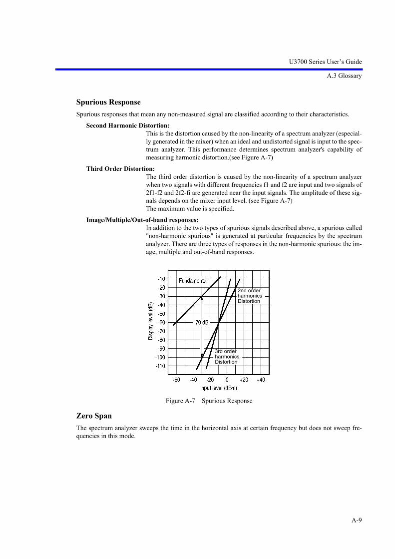
U3700 Series User’s Guide
A.3 Glossary
A-9
Spurious Response
Spurious responses that mean any non-measured signal are classified according to their characteristics.
Second Harmonic Distortion:This is the distortion caused by the non-linearity of a spectrum analyzer (especial-ly generated in the mixer) when an ideal and undistorted signal is input to the spec-trum analyzer. This performance determines spectrum analyzer's capability ofmeasuring harmonic distortion.(see Figure A-7)
Third Order Distortion:The third order distortion is caused by the non-linearity of a spectrum analyzerwhen two signals with different frequencies f1 and f2 are input and two signals of2f1-f2 and 2f2-fi are generated near the input signals. The amplitude of these sig-nals depends on the mixer input level. (see Figure A-7)The maximum value is specified.
Image/Multiple/Out-of-band responses:In addition to the two types of spurious signals described above, a spurious called"non-harmonic spurious" is generated at particular frequencies by the spectrumanalyzer. There are three types of responses in the non-harmonic spurious: the im-age, multiple and out-of-band responses.
Figure A-7 Spurious Response
Zero Span
The spectrum analyzer sweeps the time in the horizontal axis at certain frequency but does not sweep fre-quencies in this mode.
2nd orderharmonicsDistortion
3rd orderharmonicsDistortion

U3700 Series User’s Guide
A.3 Glossary
A-10
Occupied Bandwidth
When information is transmitted through radio waves, the spread of the frequency spectrum is caused alongwith the modulation. The occupied bandwidth is defined as the width of frequency spectrum that occupies99% of total average power. (see Figure A-8)
Figure A-8 Occupied Bandwidth
Bandwidth Selectivity
The band-pass filter normally has a Gaussian distribution characteristics instead of the so-called rectangularcharacteristic. Consequently, if two adjacent signals of different levels exist, the smaller signal hides in theskirt of the larger signal. (See Figure A-9)
Therefore, the bandwidth at a certain attenuation range (60 dB) should also be defined. The ratio between the3 dB width and 60 dB width is expressed as the bandwidth selectivity.
Figure A-9 Bandwidth Selectivity
P=0.5%P=0.5%
P=99%
Am
plitu
de
FUFLFrequency
00
Occupied Bandwidth
(a) Separation of different level signals (b) IF filter selectivity

U3700 Series User’s Guide
A.3 Glossary
A-11
Bandwidth Accuracy
The bandwidth accuracy of the resolution bandwidth filter is expressed by the deviation from the nominalvalue of the 3 dB-lowered point. This specification has almost no effect when measuring the level of a con-tinuous signal, but it should be taken into consideration when measuring the level of a noise signal.
Bandwidth Switching Uncertainty
Several resolution bandwidth filters are used to obtain the optimal resolution in a signal spectrum analysisaccording to the frequency span. When switching from one resolution bandwidth filter to another while mea-suring one signal, an error is generated because of the differences in loss between resolution bandwidth fil-ters. This error is defined as the bandwidth switching uncertainty.
Figure A-10 Bandwidth Switching Uncertainty
Average Noise Level
This sensitivity represents spectrum analyzer's capability of detecting the smallest signal and is directly re-lated with noises generated from a spectrum analyzer itself. The sensitivity, however, varies depends on theused resolution bandwidth. In general, the maximum input sensitivity of a spectrum analyzer is expressed asaverage noise level when the instrument is used with its minimum resolution bandwidth.
1 dBSwitching uncertainty

U3700 Series User’s Guide
A.3 Glossary
A-12
VSWR: Voltage Standing Wave Ratio
This shows the state of impedance matching when a spectrum analyzer is connected to a signal source thatincludes ideal and nominal output impedance. The VSWR is expressed as the ratio of the maximum value tominimum value of a standing wave, which consists of traveling and reflected waves. The VSWR is anotherexpression of the reflection coefficient or return loss.
Referring to Figure A-11, the signal E1 at the receiving end (the spectrum analyzer input section) is the sameas the signal E0 at the transmitting end if the impedance of the receiving end is matched to that of the trans-mitting end.The reflection coefficient is expressed in the formula shown below when the reflected wave ER exists due toa mismatch between the impedances.
Reflection coefficient m = Reflected wave ER / Traveling wave E0
The Return loss is expressed in the formula shown below.
Return loss = 20 log ER / E0 [dB]
VSWR = (E0 + ER) / (E0 - ER)
The relationship of VSWR with the reflection coefficient is as follows.
VSWR = (1 + | m | ) / (1 - | m | )
The range of VSWR is between 1 and the nearer to 1 this value is, the better the state of impedance match-ing is.
Figure A-11 VSWR
Traveling wave
E1 ReceiverSender E0
Spectrum analyzer
Reflected wave
Signal to be measured

U3700 Series User’s Guide
A.4 dB Conversion Formula
A-13
A.4 dB Conversion Formula
1. Definitions
0 dBV = 1 Vrms Y dBV = 20 log
0 dBm = 1 mW Y dBm = 10 log
0 dBV = 1 Vrms Y dBV = 20 log
0 dBpw = 1 pW Y dBpw = 10 log
2. Conversion formulasIf R = 50 : If R = 75 :dBV (dBm - 13 dB) dBV (dBm - 11 dB)dBV (dBm + 107 dB) dBV (dBm + 109 dB)dBVemf (dBm + 113 dB) dBVemf (dBm + 115 dB)dBpw (dBm + 90 dB) dBpw (dBm + 90 dB)
3. Examples
Converting 1 mV into dBV: 20 log = 20 log 103 = 60 dBV
Converting 0 dBm into dBV: 0 dBm + 107 dB = 107 dBV(R = 50 )
0 dBm + 109 dB = 109 dBV(R = 75 )
Converting 60 dBV into dBm: 60 dBV - 107 dB = -47 dBm(R = 50 )
60 dBV - 109 dB = -49 dBm(R = 75 )
Converting 10 V/m into dBV/m: 20 log = 140 dBV/m
4. Relationship between dBm and Watt
+50 dBm +40 dBm +30 dBm +20 dBm +10 dBm +0 dBm -10 dBm -20 dBm -30 dBm
100 W 10 W 1 W 100 mW 10 mW 1 mW 0.1 mW 0.01 mW 0.001 mW
1 VX V
1 mWX mW
1 VX V
1 pWX pW
1 V1 mV
{{
1 V/m10 V/m

U3700 Series User’s Guide
A.5 Menu Map List
A-14
A.5 Menu Map List
• SYSTEM (1)
SYSTEM
Version
Annotations ON/OFF
Frequency Reference
Remote Control
Trace Points 501/1001
Calibration
More 1/2
Frequency Reference INT/EXT/XTL
Ref Freq
Ref Freq 10 MHz
Calibrate ALL
Each Item
Report HIDE/SHOW
Calibration F Int Ref
Calibration Corrections ON/OFF
Frequency Correction ON/OFF
Total Gain RF Path 1
Total Gain RF Path 2
Step ATT CAL
RBW CAL
PBW
Coarse
Fine (U3751/U3771/U3772)Store
Default
GPIB Address
LAN IP Address
R3162 Mode ON/OFF
Parser AT/SCPI
GPIB Address
LAN IP Address
R3131 Mode ON/OFF
Parser AT/SCPI
U3751/U3771/U3772
U3741
(a)

U3700 Series User’s Guide
A.5 Menu Map List
A-15
SYSTEM (2)
Color Pattern
User Password
Date Time
Copy Config
Self Test
Factory Init
Color1
Color2
Black and White
White and Black
Copy
Copy Device FILE/PRT
Screen Shot Config
Print ConfigFile Format PNG/BMP
Auto Inc ON/OFF
Auto Inc Index
Menu ON/OFF
File Control
Media
Paper Format
Color Mode Color/Gray
Menu ON/OFF
Config Driver
Rename File
Remove File
Write Protect ON/OFF
Execute Self Test
Edit Date Time
Format
Show ON/OFF
(a)

U3700 Series User’s Guide
A.5 Menu Map List
A-16
• APPLI
• FILE
APPLI
Spectrum Analyzer
2 Channels Viewer 2 Channel ON/OFF
Spectrum RF1
Spectrum RF2
2 Channel Preset
Context RF2|RF1
FILE
Save
Save as
File Control
Recall
Items
Title
Media
Auto-name Radix
Auto name Index
File Format BIN/XML
Format Media
Rename File
Remove File
Copy All to Flash
Copy All to USB
Write Protect ON/OFF
More 1/2

U3700 Series User’s Guide
A.5 Menu Map List
A-17
• MEAS 1 (1)
MEAS 1
Channel Power
Total Power
Average Power
OBW
ACP
Spectrum Emission
Spurious
Channel Power Execute ON/OFF
Average Control
On Trace A/B/C
Channel Position
Channel Width
Default Conditions
Averaging ON/OFF
Max Sweep Count
Average ONCE/SLIDE
(a)(b)(c)(d)
(e)(f)(g)
(a)
Restore Defaults
Save Defaults
Total Power Execute ON/OFF
Average Control
On Trace A/B/C
Default Conditions
Averaging ON/OFF
Max Sweep Count
Average ONCE/SLIDE
(b)
Restore Defaults
Save Defaults
Average Power Execute ON/OFF
Average Control
On Trace A/B/C
Window
Default Conditions
Averaging ON/OFF
Max Sweep Count
Average ONCE/SLIDE
(c)
Range FULL/WIN
Window Position
Window Width
Restore Defaults
Save Defaults
Restore Defaults
Save Defaults
OBW Execute ON/OFF
Average Control
On Trace A/B/C
%OBW
Default Conditions
Averaging ON/OFF
Max Sweep Count
Average ONCE/SLIDE
(d)

U3700 Series User’s Guide
A.5 Menu Map List
A-18
MEAS 1 (2)
Spectrum Emission Execute ON/OFF
Average Control
On Trace A/B/C
Config
Bands Definition
Default Conditions
Averaging ON/OFF
Max Sweep Count
Average ONCE/SLIDE
(f)
Spurious Execute ON/OFF
On Trace A/B/C
Bands Definition
Results
Table No. 1/2/3
Default Conditions
Insert Band
Delete Band
Init Table
Table No. 1/2/3
(g)
Restore Defaults
Save Defaults
ACP Execute ON/OFF
Average Control
Mode FULL/CARR
Config
Channel Definition
Graph ON/OFF
Default Conditions
Averaging ON/OFF
Max Sweep Count
Average ONCE/SLIDE
(e)
Insert Channel
Delete Channel
Init Table
Carrier Bandwidth
Ch Windows ON/OFF
Nyquist Filter ON/OFF
Nyq Symbol Rate
Nyq Roll Off Factor
Carrier Bandwidth
Ref Power CHN/PEAK
Ch Windows ON/OFF
Show Mask ON/OFF
Nyquist Filter ON/OFF
Nyq Symbol Rate
Nyq Roll Off Factor
Delete Band
Init Table
Restore Defaults
Save Defaults
Previous Band
Next Band
Restore Defaults
Save Defaults
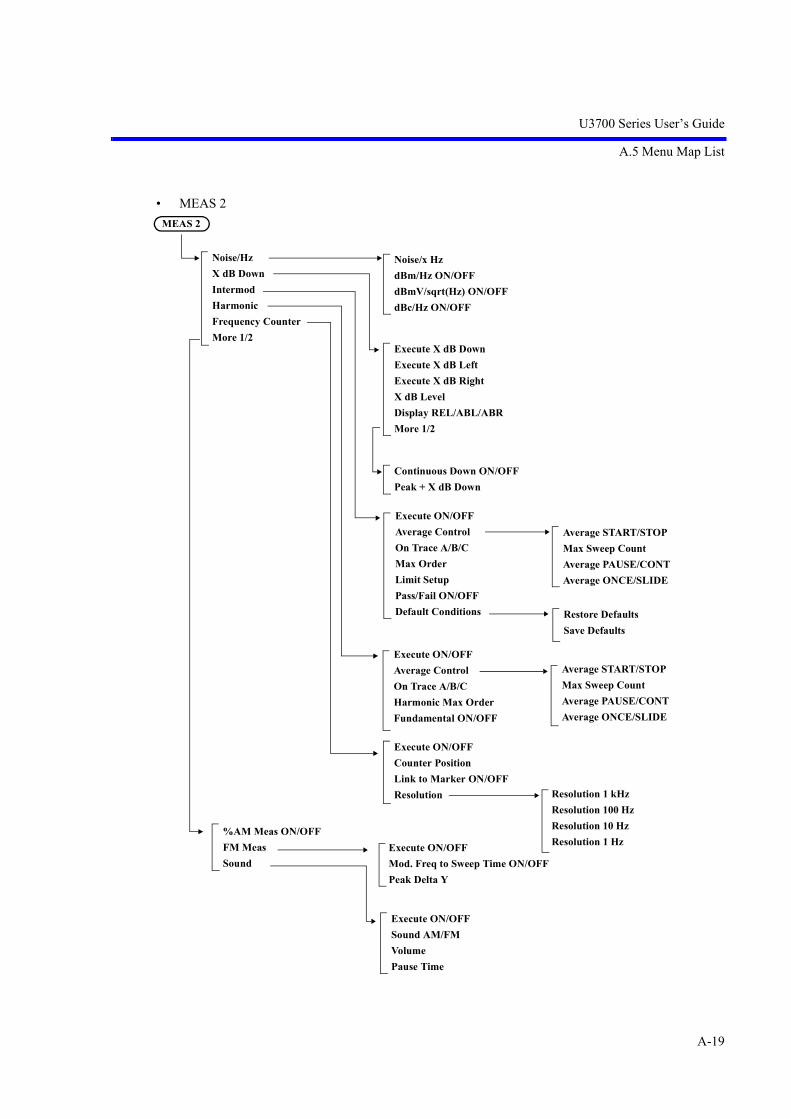
U3700 Series User’s Guide
A.5 Menu Map List
A-19
• MEAS 2MEAS 2
Noise/Hz
X dB Down
Intermod
Harmonic
Frequency Counter
More 1/2
Noise/x Hz
dBm/Hz ON/OFF
dBmV/sqrt(Hz) ON/OFF
dBc/Hz ON/OFF
Continuous Down ON/OFF
Peak + X dB Down
Execute X dB Down
Execute X dB Left
Execute X dB Right
X dB Level
Display REL/ABL/ABR
More 1/2
Average START/STOP
Max Sweep Count
Average PAUSE/CONT
Average ONCE/SLIDE
Restore Defaults
Save Defaults
Average START/STOP
Max Sweep Count
Average PAUSE/CONT
Average ONCE/SLIDE
Resolution 1 kHz
Resolution 100 Hz
Resolution 10 Hz
Resolution 1 Hz
Execute ON/OFF
Counter Position
Link to Marker ON/OFF
Resolution
Execute ON/OFF
Average Control
On Trace A/B/C
Max Order
Limit Setup
Pass/Fail ON/OFF
Default Conditions
Execute ON/OFF
Average Control
On Trace A/B/C
Harmonic Max Order
Fundamental ON/OFF
Execute ON/OFF
Mod. Freq to Sweep Time ON/OFF
Peak Delta Y
%AM Meas ON/OFF
FM Meas
Sound
Execute ON/OFF
Sound AM/FM
Volume
Pause Time

U3700 Series User’s Guide
A.5 Menu Map List
A-20
• TRACE
Subtract
Store
Trace A/B/C
OFF
A-BA
B-AA
B-AB
A-BB
Display Line ON/OFF
More 1/2
OFF
A-BC
B-AC
A-DLA
B-DLB
Display Line ON/OFF
TRCA
TRCB
TRCC
Trace A/B/C
TRACE
Refresh
Calc
Detector
Detector AUTO/MNL
Det Avg Mode RMS/Video
Math
Trace A/B/C
Refresh(Write)
View
Blank
Trace A/B/C
Write
Min Hold
Max Hold
Average
Power Average
Max Hold Continuous
Trace A/B/C
Average START/STOP
Max Sweep Count
Average PAUSE/CONT
Average ONCE/SLIDE
Average START/STOP
Max Sweep Count
Average PAUSE/CONT
Average ONCE/SLIDE
Normal
Posi
Nega
Sample
Average
Quasi Peak
Trace A/B/C

U3700 Series User’s Guide
A.5 Menu Map List
A-21
• MKR
MKR
Select Marker
Marker ON/OFF
Marker Trace A/B/C
Delta Mode
Peak Menu
Clear All
More 1/2
Others HIDE/SHOW
Clear Others
Display List ON/OFF
Mkr Step AUTO/MNL
Mode Index/Value
Signal Track
Delta ON/OFF
Ref Object
Fixed Mkr ON/OFF
1/Delta Mkr ON/OFF
Select Marker
Next Peak
Next Peak Right
Next Peak Left
Config
More 1/2
Min Peak
Next Min Peak
Min Max Peak
Peak List Frequency
Peak List Level
Display List ON/OFF
Peak Delta Y
Continuous Peak ON/OFF
X-Search Domain
Y- Search DomainCouple to Win OFF/IN/OUT
Window Position
Window Width
Couple to DL OFF/ABV/BLW
Display Line ON/OFF
Couple to Line 1 OFF/ABV/BLW
Couple to Line 2 OFF/ABV/BLW
Edit Limit Lines
Limit Line 1/2
Delete Entry
Insert Entry
Table Init
Signal Track ON/OFF
Y Range ON/OFF
(a)
(a)Peak Menu
Reference Marker
Reference Line

U3700 Series User’s Guide
A.5 Menu Map List
A-22
• PEAK
• MKR
PEAK
Select Marker
Next Peak
Next Peak Right
Next Peak Left
Config
More 1/2
Min Peak
Next Min Peak
Min Max Peak
Peak List Frequency
Peak List Level
Display List ON/OFF
Peak Delta Y
Continuous Peak ON/OFF
X-Search Domain
Y- Search DomainCouple to Win OFF/IN/OUT
Window Position
Window Width
Couple to DL OFF/ABV/BLW
Display Line ON/OFF
Couple to Line 1 OFF/ABV/BLW
Couple to Line 2 OFF/ABV/BLW
Edit Limit Lines Limit Line 1/2
Delete Entry
Insert Entry
Table Init
MKR
Mkr to CF
Mkr to Ref
Peak to CF
Peak to Ref
Delta to Span
Delta to CF
More 1/2
Mkr to CF Step
Delta to CF Step
Mkr to Mkr Step
Delta to Mkr Step

U3700 Series User’s Guide
A.5 Menu Map List
A-23
• TG (Option)
• FREQUENCY
TG
TG ON/OFF
TG Level
TG Level Offset ON/OFF
TG Freq. Offset ON/OFF
Normalize
Reference Line ON/OFF
Capture Normz Data
Normalize Correction ON/OFF
Trace A/B/C
VSWR ON/OFF
Delta Ref Line ON/OFF
Reference Line ON/OFF
FREQUENCY
Center
Start
Stop
Frequency Offset ON/OFF
CF Step Size AUTO/MNL
Channel Input
More 1/2Freq Input Mode CALC/TABLE
Center CH ON/OFF
Start CH ON/OFF
Stop CH ON/OFF
Start CH Offset ON/OFF
Stop CH Offset ON/OFF
Channels Config
Edit Channel Formula
Edit Channel Table
Formula 1 ON/OFF
Formula 2 ON/OFF
Formula 3 ON/OFF
Insert Line
Delete Line
Table Init
Signal Identification ON/OFF
Image Suppression ON/OFF
(U3751/U3771/U3772)

U3700 Series User’s Guide
A.5 Menu Map List
A-24
• SPAN
• AMPLITUDE
SPAN
Span
Full Span
Zero Span
Last Span
Peak Zoom
Auto Tune
AMPLITUDE
Ref Level
ATT
dB/div
Vertical Scale LIN/LOG
Units
Slide Screen ON/OFF
More 1/2
Ref Offset ON/OFF
Input Impedance 50/75
High Sensitivity ON/OFF
Correction Factor ON/OFF
Edit Corr Factor
Round Grid Values ON/OFF
ATT AUTO/MNL
Min ATT
Attenuation 0 dB
10 dB/div
5 dB/div
2 dB/div
1 dB/div
0.5 dB/div
dBm
dBmV
dBV
dBVemf
dBpW
Watts
Volts
Insert
Delete
Init Table

U3700 Series User’s Guide
A.5 Menu Map List
A-25
• EXT CFG (Extended Configuration options) (1)
EXT CFG
Sweep Mode SGL/CNT
Trigger
Gated Sweep
Measuring Window
Limit Lines
Ref/Disp Lines
Zoom and Contexts
Source
Ext Trigger Level
Level
Slope NEG/POS
Delay
Free Run
Video
External
IF
Window HIDE/SHOW
Window Position
Window Width
Window Sweep ON/OFF
Pass/Fail ON/OFF
Line 1 ON/OFF
Line 1 ABV/BLW
Line 2 ON/OFF
Line 2 ABV/BLW
Pass/Fail Config
Limit Line EditX ABS/CF/FA
Shift X ON/OFF
Y ABS/REF/DL
Shift Y ON/OFF
Display Line ON/OFF
Limit Line 1/2
Delete Entry
Insert Entry
Table Init
Display Line ON/OFF
Reference Line ON/OFF
Gated Sweep ON/OFF
Source
Slope NEG/POS
Gate Delay
Gate Width
External
IF
(a)

U3700 Series User’s Guide
A.5 Menu Map List
A-26
EXT CFG (Extended Configuration options) (1)
• CPL (Coupled function)
Freq vs Time ON/OFF
Frequency Pos
Context A/B
Graphic Z 1 Screen
Graphic Z 2 Screens
Freq Zoom
Freq vs Time
Time vs Time
Reset Context
Context A/B
Graphic Zoom 1 ON/OFF
Window Position
Window Width
Graphic Zoom 2 ON/OFF
Window Position
Window Width
Frequency Zoom ON/OFF
Zoom Position
Zoom Width
Context A/B
(a)
CPL
RBW AUTO/MNL
VBW AUTO/MNL
Sweep Time AUTO/MNL
EMC
All Auto
More 1/2
SPAN/RBW ON/OFF
VBW/RBW ON/OFF
PLL BW
EMC Filter ON/OFF
RBW Auto
RBW 200 Hz
RBW 9 kHz
RBW 120 kHz
RBW 1 MHz
Auto
Medium
Narrow

U3700 Series User’s Guide
A.6 TV Channel Table (Japan)
A-27
A.6 TV Channel Table (Japan)
A.6.1 CATV Channel Number and Frequency
Analyzer's channel Channel Frequency range
(MHz)Center frequency
(MHz)Picture frequency
(MHz)Sound frequency
(MHz)
1 1 90.00 ~ 96.00 93 91.25 95.75
2 2 96.00 ~ 102.00 99 97.25 101.75
3 3 102.00 ~ 108.00 105 103.25 107.75
4 4 170.00 ~ 176.00 173 171.25 175.75
5 5 176.00 ~ 182.00 179 177.25 181.75
6 6 182.00 ~ 188.00 185 183.25 187.75
7 7 188.00 ~ 194.00 191 189.25 193.75
8 8 192.00 ~ 198.00 195 193.25 197.75
9 9 198.00 ~ 204.00 201 199.25 203.75
10 10 204.00 ~ 210.00 207 205.25 209.75
11 11 210.00 ~ 216.00 213 211.25 215.75
12 12 216.00 ~ 222.00 219 217.25 221.75
13 Cl3 108.00 ~ 114.00 111 l09.25 113.25
14 C14 114.00 ~ 120.00 117 115.25 119.75
15 C15 120.00 ~ 126.00 123 121.25 125.75
16 C16 126.00 ~ 132.00 129 127.25 131.75
17 C17 132.00 ~ 138.00 135 133.25 137.75
18 C18 138.00 ~ 144.00 141 139.25 143.75
19 C19 144.00 ~ 150.00 147 145.25 149.75
20 C20 150.00 ~ 156.00 153 151.25 155.75
21 C21 156.00 ~ 162.00 159 157.25 161.75
22 C22 164.00 ~ 170.00 167 165.25 169.75
23 C23 222.00 ~ 228.00 225 223.25 227.75
24 C24 230.00 ~ 236.00 233 231.25 235.75
25 C25 236.00 ~ 242.00 239 237.25 241.75
26 C26 242.00 ~ 248.00 245 243.25 247.75
27 C27 248.00 ~ 254.00 251 249.25 253.75
28 C28 252.00 ~ 258.00 255 253.25 257.75
29 C29 258.00 ~ 264.00 261 259.25 263.75
30 C30 264.00 ~ 270.00 267 265.25 269.75
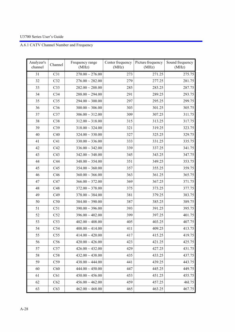
U3700 Series User’s Guide
A.6.1 CATV Channel Number and Frequency
A-28
31 C31 270.00 ~ 276.00 273 271.25 275.75
32 C32 276.00 ~ 282.00 279 277.25 281.75
33 C33 282.00 ~ 288.00 285 283.25 287.75
34 C34 288.00 ~ 294.00 291 289.25 293.75
35 C35 294.00 ~ 300.00 297 295.25 299.75
36 C36 300.00 ~ 306.00 303 301.25 305.75
37 C37 306.00 ~ 312.00 309 307.25 311.75
38 C38 312.00 ~ 318.00 315 313.25 317.75
39 C39 318.00 ~ 324.00 321 319.25 323.75
40 C40 324.00 ~ 330.00 327 325.25 329.75
41 C41 330.00 ~ 336.00 333 331.25 335.75
42 C42 336.00 ~ 342.00 339 337.25 341.75
43 C43 342.00 ~ 348.00 345 343.25 347.75
44 C44 348.00 ~ 354.00 351 349.25 353.75
45 C45 354.00 ~ 360.00 357 355.25 359.75
46 C46 360.00 ~ 366.00 363 361.25 365.75
47 C47 366.00 ~ 372.00 369 367.25 371.75
48 C48 372.00 ~ 378.00 375 373.25 377.75
49 C49 378.00 ~ 384.00 381 379.25 383.75
50 C50 384.00 ~ 390.00 387 385.25 389.75
51 C51 390.00 ~ 396.00 393 391.25 395.75
52 C52 396.00 ~ 402.00 399 397.25 401.75
53 C53 402.00 ~ 408.00 405 403.25 407.75
54 C54 408.00 ~ 414.00 411 409.25 413.75
55 C55 414.00 ~ 420.00 417 415.25 419.75
56 C56 420.00 ~ 426.00 423 421.25 425.75
57 C57 426.00 ~ 432.00 429 427.25 431.75
58 C58 432.00 ~ 438.00 435 433.25 437.75
59 C59 438.00 ~ 444.00 441 439.25 443.75
60 C60 444.00 ~ 450.00 447 445.25 449.75
61 C61 450.00 ~ 456.00 453 451.25 455.75
62 C62 456.00 ~ 462.00 459 457.25 46l.75
63 C63 462.00 ~ 468.00 465 463.25 467.75
Analyzer's channel Channel Frequency range
(MHz)Center frequency
(MHz)Picture frequency
(MHz)Sound frequency
(MHz)

U3700 Series User’s Guide
A.6.2 VHF/UHF Channel Number and Frequency
A-29
A.6.2 VHF/UHF Channel Number and Frequency
1. VHF
2. UHF
Analyzer's channel Channel Frequency range
(MHz)Center frequency
(MHz)Picture frequency
(MHz)Sound frequency
(MHz)
1 1 90.00 ~ 96.00 93 91.25 95.75
2 2 96.00 ~ 102.00 99 97.25 101.75
3 3 102.00 ~ 108.00 105 103.25 107.75
4 4 170.00 ~ 176.00 173 171.25 175.75
5 5 176.00 ~ 182.00 179 177.25 181.75
6 6 182.00 ~ 188.00 185 183.25 187.75
7 7 188.00 ~ 194.00 191 189.25 193.75
8 8 192.00 ~ 198.00 195 193.25 197.75
9 9 198.00 ~ 204.00 201 199.25 203.75
10 10 204.00 ~ 210.00 207 205.25 209.75
11 11 210.00 ~ 216.00 213 211.25 215.75
12 12 216.00 ~ 222.00 219 217.25 221.75
Analyzer's channel Channel Frequency range
(MHz)Center frequency
(MHz)Picture frequency
(MHz)Sound frequency
(MHz)
13 13 470.00 ~ 476.00 473 471.25 475.75
14 14 476.00 ~ 482.00 479 477.25 481.75
15 15 482.00 ~ 488.00 485 483.25 487.75
16 16 488.00 ~ 494.00 491 489.25 493.75
17 17 494.00 ~ 500.00 497 495.25 499.75
18 18 500.00 ~ 506.00 503 501.25 505.75
19 19 506.00 ~ 512.00 509 507.25 511.75
20 20 512.00 ~ 518.00 515 513.25 517.75
21 21 518.00 ~ 524.00 521 519.25 523.75
22 22 524.00 ~ 530.00 527 525.25 529.75
23 23 530.00 ~ 536.00 533 531.25 535.75
24 24 536.00 ~ 542.00 539 537.25 541.75
25 25 542.00 ~ 548.00 545 543.25 547.75
26 26 548.00 ~ 554.00 551 549.25 553.75
27 27 554.00 ~ 560.00 557 555.25 559.75
28 28 560.00 ~ 566.00 563 561.25 565.75

U3700 Series User’s Guide
A.6.2 VHF/UHF Channel Number and Frequency
A-30
29 29 566.00 ~ 572.00 569 567.25 57l.75
30 30 572.00 ~ 578.00 575 573.25 577.75
31 31 578.00 ~ 584.00 581 579.25 583.75
32 32 584.00 ~ 590.00 587 585.25 589.75
33 33 590.00 ~ 596.00 593 59l.25 595.75
34 34 596.00 ~ 602.00 599 597.25 601.75
35 35 602.00 ~ 608.00 605 603.25 607.75
36 36 608.00 ~ 614.00 611 609.25 613.75
37 37 614.00 ~ 620.00 617 615.25 619.75
38 38 620.00 ~ 626.00 623 621.25 625.75
39 39 626.00 ~ 632.00 629 627.25 631.75
40 40 632.00 ~ 638.00 635 633.25 637.75
41 41 638.00 ~ 644.00 641 639.25 643.75
42 42 644.00 ~ 650.00 647 645.25 649.75
43 43 650.00 ~ 656.00 653 651.25 655.75
44 44 656.00 ~ 662.00 659 657.25 661.75
45 45 662.00 ~ 668.00 665 663.25 667.75
46 46 668.00 ~ 674.00 671 669.25 673.75
47 47 674.00 ~ 680.00 677 675.25 679.75
48 48 680.00 ~ 686.00 683 681.25 685.75
49 49 686.00 ~ 692.00 689 687.25 691.75
50 50 692.00 ~ 698.00 695 693.25 697.75
51 51 698.00 ~ 704.00 701 699.25 703.75
52 52 704.00 ~ 710.00 707 705.25 709.75
53 53 710.00 ~ 716.00 713 711.25 715.75
54 54 716.00 ~ 722.00 719 717.25 721.75
55 55 722.00 ~ 728.00 725 723.25 727.75
56 56 728.00 ~ 734.00 731 729.25 733.75
57 57 734.00 ~ 740.00 737 735.25 739.75
58 58 740.00 ~ 746.00 743 741.25 745.75
59 59 746.00 ~ 752.00 749 747.25 751.75
60 60 752.00 ~ 758.00 755 753.25 757.75
61 61 758.00 ~ 764.00 761 759.25 763.75
62 62 764.00 ~ 770.00 767 765.25 769.75
Analyzer's channel Channel Frequency range
(MHz)Center frequency
(MHz)Picture frequency
(MHz)Sound frequency
(MHz)

U3700 Series User’s Guide
A.6.3 Terrestrial Digital Broadcasting Channel Number and Frequency
A-31
A.6.3 Terrestrial Digital Broadcasting Channel Number and Frequency
• UHF that supports terrestrial digital broadcasting
Analyzer's channel Channel Frequency range
(MHz)Center frequency
(MHz)
13 13 470.00 ~ 476.00 473.142857
14 14 476.00 ~ 482.00 479.142857
15 15 482.00 ~ 488.00 485.142857
16 16 488.00 ~ 494.00 491.142857
17 17 494.00 ~ 500.00 497.142857
18 18 500.00 ~ 506.00 503.142857
19 19 506.00 ~ 512.00 509.142857
20 20 512.00 ~ 518.00 515.142857
21 21 518.00 ~ 524.00 521.142857
22 22 524.00 ~ 530.00 527.142857
23 23 530.00 ~ 536.00 533.142857
24 24 536.00 ~ 542.00 539.142857
25 25 542.00 ~ 548.00 545.142857
26 26 548.00 ~ 554.00 551.142857
27 27 554.00 ~ 560.00 557.142857
28 28 560.00 ~ 566.00 563.142857
29 29 566.00 ~ 572.00 569.142857
30 30 572.00 ~ 578.00 575.142857
31 31 578.00 ~ 584.00 581.142857
32 32 584.00 ~ 590.00 587.142857
33 33 590.00 ~ 596.00 593.142857
34 34 596 .00 ~ 602.00 599.142857
35 35 602.00 ~ 608.00 605.142857
36 36 608.00 ~ 614.00 611.142857
37 37 614.00 ~ 620.00 617.142857
38 38 620.00 ~ 626.00 623.142857
39 39 626.00 ~ 632.00 629.142857
40 40 632.00 ~ 638.00 635.142857
41 41 638.00 ~ 644.00 641.142857
42 42 644.00 ~ 650.00 647.142857
43 43 650.00 ~ 656.00 653.142857
44 44 656.00 ~ 662.00 659.142857

U3700 Series User’s Guide
A.6.3 Terrestrial Digital Broadcasting Channel Number and Frequency
A-32
45 45 662.00 ~ 668.00 665.142857
46 46 668.00 ~ 674.00 671.142857
47 47 674.00 ~ 680.00 677.142857
48 48 680.00 ~ 686.00 683.142857
49 49 686.00 ~ 692.00 689.142857
50 50 692.00 ~ 698.00 695.142857
51 51 698.00 ~ 704.00 701.142857
52 52 704.00 ~ 710.00 707.142857
53 53 710.00 ~ 716.00 713.142857
54 54 716.00 ~ 722.00 719.142857
55 55 722.00 ~ 728.00 725.142857
56 56 728.00 734.00 731.142857
57 57 734.00 740.00 737.142857
58 58 740.00 746.00 743.142857
59 59 746.00 752.00 749.142857
60 60 752.00 758.00 755.142857
61 61 758.00 764.00 761.142857
62 62 764.00 770.00 767.142857
Analyzer's channel Channel Frequency range
(MHz)Center frequency
(MHz)

U3700 Series User’s Guide
A.6.4 Satellite Broadcasting (BS-IF Band) Channel Number and Frequency
A-33
A.6.4 Satellite Broadcasting (BS-IF Band) Channel Number and Frequency
A.6.5 110 CS (CS-IF Band) Channel Number and Frequency
Analyzer's channel Channel Frequency range
(MHz)Center frequency
(MHz)
1 BS-1 1032.23 ~ 1066.73 1049.48
3 BS-3 1070.59 ~ 1105.09 1087.84
5 BS-5 1112.70 ~ 1139.70 1126.20
7 BS-7 1151.06 ~ 1178.06 1164.56
9 BS-9 1189.42 ~ 1216.42 1202.92
11 BS-11 1227.78 ~ 1254.78 1241.28
13 BS-13 1262.39 ~ 1296.89 1279.64
15 BS-15 1300.75 ~ 1335.25 1318.00
17 BS-17 1339.11 ~ 1373.61 1356.36
19 BS-19 1377.47 ~ 1411.97 1394.72
21 BS-21 1415.83 ~ 1450.33 1433.08
23 BS-23 1454.19 ~ 1488.69 1471.44
Analyzer's channel Channel Frequency range
(MHz)Center frequency
(MHz)
2 ND2 1595.75 ~ 1630.25 1613
4 ND4 1635.75 ~ 1670.25 1653
6 ND6 1675.75 ~ 1710.25 1693
8 ND8 1715.75 ~ 1750.25 1733
10 NDl0 1755.75 ~ 1790.25 1773
12 ND12 1795.75 ~ 1830.25 1813
14 ND14 1835.75 ~ 1870.25 1853
16 ND16 1875.75 ~ 1910.25 1893
18 ND18 1915.75 ~ 1950.25 1933
20 ND20 1955.75 ~ 1990.25 1973
22 ND22 1995.75 ~ 2030.25 2013
24 ND24 2035.75 ~ 2070.25 2053


EXT-1
Uni
t:mm
NO
TETh
is d
raw
ing
show
s ext
erna
l dim
ensi
ons o
fth
is in
stru
men
t.Th
e di
ffere
nce
in p
rodu
cts a
nd o
ptio
nsus
ed c
an c
ause
a c
hang
e in
the
appe
aran
ceof
the
inst
rum
ent.
U37
41 D
IME
NS
ION
AL
OU
TL
INE
DR
AW
ING
DIMENSIONAL OUTLINE DRAWING

EXT-2
Uni
t:mm
NO
TETh
is d
raw
ing
show
s ext
erna
l dim
ensi
ons o
fth
is in
stru
men
t.Th
e di
ffere
nce
in p
rodu
cts a
nd o
ptio
nsus
ed c
an c
ause
a c
hang
e in
the
appe
aran
ceof
the
inst
rum
ent.
U37
51 D
IME
NS
ION
AL
OU
TL
INE
DR
AW
ING
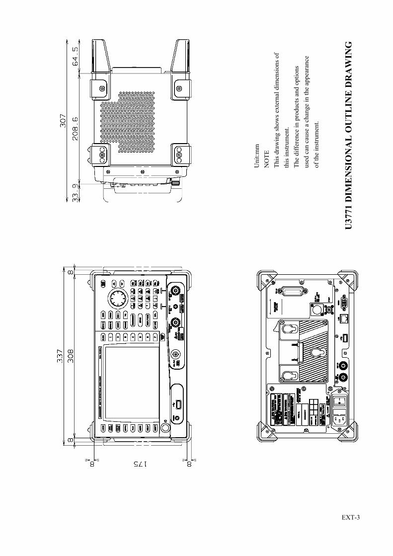
EXT-3
Uni
t:mm
NO
TE
This
dra
win
g sh
ows e
xter
nal d
imen
sion
s of
this
inst
rum
ent.
The
diffe
renc
e in
pro
duct
s and
opt
ions
used
can
cau
se a
cha
nge
in th
e ap
pear
ance
of th
e in
stru
men
t.
U37
71 D
IME
NS
ION
AL
OU
TL
INE
DR
AW
ING

EXT-4
Uni
t:mm
NO
TE
This
dra
win
g sh
ows e
xter
nal d
imen
sion
s of
this
inst
rum
ent.
The
diffe
renc
e in
pro
duct
s and
opt
ions
used
can
cau
se a
cha
nge
in th
e ap
pear
ance
of th
e in
stru
men
t.
U37
72 D
IME
NS
ION
AL
OU
TL
INE
DR
AW
ING

GUIDE-1
U3741/U3751/U3771/U3772 QUICK GUIDE
For Basic Operation
QUICK GUIDE

GUIDE-2
U3741/U3751/U3771/U3772 QUICK GUIDE

GUIDE-3
U3741/U3751/U3771/U3772 QUICK GUIDE

GUIDE-4
U3741/U3751/U3771/U3772 QUICK GUIDE

U3700 Series User’s Guide
ALPHABETICAL INDEX
I-1
[Symbol]%AM Meas ON/OFF .............................. 5-37, 5-40%OBW .................................................... 5-25, 5-30
[Numerics]0.5 dB/div ................................................ 5-62, 5-631 dB/div ................................................... 5-62, 5-631/Delta Mkr ON/OFF .............................. 5-47, 5-4810 dB/div ................................................. 5-62, 5-63110 CS (CS-IF Band) .............................. A-332 Channel ON/OFF ................................. 5-172 Channel Preset ..................................... 5-172 Channels Viewer .................................. 5-172 dB/div ................................................... 5-62, 5-635 dB/div ................................................... 5-62, 5-63
[A]A-BA ................................................... 5-43, 5-46A-BB ................................................... 5-43, 5-46A-BC ................................................... 5-43, 5-46About Calibration ................................... 9-2About Replacement of Limited-Life Parts 9-2Accessories ............................................. 8-2ACP ......................................................... 5-25, 5-30A-DLA ................................................ 5-43, 5-46All Auto .................................................. 5-72, 5-73AMPLITUDE ......................................... 5-62Amplitude ............................................... 7-3, 7-7,
7-11Amplitude Accuracy ............................... 7-4, 7-8,
7-12Annotations ON/OFF .............................. 5-7, 5-9APPLI ..................................................... 5-17Arrangement of the three status registers 6-14AT Command Index ............................... 6-19AT Command List .................................. 6-25ATT ......................................................... 5-62ATT AUTO/MNL ................................... 5-62Attenuation 0 dB ..................................... 5-62Auto ........................................................ 5-72, 5-73Auto Inc Index ........................................ 5-8, 5-13Auto Inc ON/OFF ................................... 5-8, 5-13Auto name Index ..................................... 5-18, 5-20Auto Tune ............................................... 5-61Auto-name Radix .................................... 5-18, 5-20Average ................................................... 5-43, 5-44,
5-45Average Control ...................................... 5-25, 5-26,
5-27, 5-28, 5-29, 5-30,
5-32, 5-36, 5-38, 5-39
Average ONCE/SLIDE ........................... 5-25, 5-26, 5-27, 5-28, 5-29, 5-30, 5-32, 5-36, 5-38, 5-40, 5-43, 5-44, 5-45
Average PAUSE/CONT ......................... 5-36, 5-38, 5-40, 5-43, 5-44
Average Power ........................................ 5-25, 5-29Average START/STOP .......................... 5-36, 5-38,
5-39, 5-43, 5-44
Averaging ON/OFF ................................ 5-25, 5-26, 5-27, 5-28, 5-29, 5-30, 5-32
[B]B-AA ................................................... 5-43, 5-46B-AB ................................................... 5-43, 5-46B-AC ................................................... 5-43, 5-46Bands Definition ..................................... 5-26, 5-33,
5-34Bandwidth ............................................... 6-28Basic Measurement ................................. 4-13Basic Operation ....................................... 4-10Basic Steps for GPIB Bus Control .......... 6-55B-DLB ................................................ 5-43, 5-46Black and White ...................................... 5-8, 5-12Blank ....................................................... 5-43, 5-44Buffers .................................................... 6-10
[C]Cabinet Cleaning ..................................... 9-1Calc ......................................................... 5-43, 5-44Calibrate ALL ......................................... 5-7, 5-11Calibration .............................................. 4-13, 5-7,
5-11, 6-47Calibration Corrections ON/OFF ............ 5-7, 5-11Calibration F Int Ref ............................... 5-7, 5-11Capture Normz Data ............................... 5-55Carrier Bandwidth ................................... 5-26, 5-31,
5-32CATV ...................................................... A-27Caution when Connecting Peripherals .... 3-9Center ...................................................... 5-57
ALPHABETICAL INDEX ALPHABETICAL INDEX

U3700 Series User’s Guide
Alphabetical Index
I-2
Center CH ON/OFF ................................ 5-57, 5-58CF Step Size AUTO/MNL ..................... 5-57Ch Windows ON/OFF ............................ 5-26, 5-31,
5-32Channel Definition .................................. 5-26, 5-31Channel Input .......................................... 5-57, 5-58Channel Position ..................................... 5-25, 5-27Channel Power ........................................ 5-25, 5-27Channel Width ........................................ 5-25, 5-27Channels Config ..................................... 5-57, 5-58Charging the Battery ............................... 3-7Cleaning .................................................. 9-1Cleaning of Other Parts ........................... 9-2Clear All .................................................. 5-47, 5-48Clear Others ............................................ 5-47, 5-48CN Measurement in Terrestrial Digital Broadcasting ........................................... 4-51Coarse ..................................................... 5-7, 5-11Color Mode Color/Gray .......................... 5-8, 5-15Color Pattern ........................................... 5-8, 5-12Color1 ..................................................... 5-8, 5-12Color2 ..................................................... 5-8, 5-12Command Reference Syntax .................. 6-76Command Syntax .................................... 6-11Common Commands .............................. 6-78Condition Register .................................. 6-13Config ..................................................... 5-26, 5-31,
5-32, 5-47, 5-50, 6-50
Config Driver .......................................... 5-8, 5-15Connecting the DC Power Cable ............ 3-8Contents of This Manual ......................... 1-1Context A/B ............................................ 5-66, 5-70,
5-71Context RF2|RF1 .................................... 5-17, 5-18Continuous Down ON/OFF .................... 5-36, 5-38Continuous Peak ON/OFF ...................... 5-47, 5-50Control from a Controller ....................... 6-9Conventions of Notation Used in This Document ................................................ 1-2COPY ...................................................... 5-24Copy ........................................................ 5-8, 5-13Copy All to Flash .................................... 5-18, 5-20Copy All to USB ..................................... 5-18, 5-20Copy Config ............................................ 5-8, 5-13Copy Device FILE/PRT .......................... 5-8, 5-13Correction Factor ON/OFF ..................... 5-62, 5-64Counter .................................................... 6-42Counter Position ..................................... 5-36, 5-40Couple to DL OFF/ABV/BLW ............... 5-47, 5-50,
5-51Couple to Line 1 OFF/ABV/BLW .......... 5-47, 5-50,
5-51
Couple to Line 2 OFF/ABV/BLW .......... 5-47, 5-50, 5-51
Couple to Win OFF/IN/OUT .................. 5-47, 5-50, 5-51
CPL ......................................................... 5-72CPL (Coupled function) .......................... 5-72
[D]Data format ............................................. 6-12Date Time ............................................... 5-8, 5-12dB Conversion Formula .......................... A-13dB/div ...................................................... 5-62, 5-63dBc/Hz ON/OFF ..................................... 5-36, 5-37dBm ......................................................... 5-62, 5-63dBm/Hz ON/OFF .................................... 5-36, 5-37dBmV ...................................................... 5-62, 5-63dBV ....................................................... 5-62, 5-63dBV/sqrt(Hz) ON/OFF ......................... 5-36, 5-37dBVemf ................................................ 5-62, 5-63dBpW ...................................................... 5-62, 5-63DC Power Requirements ........................ 3-8Default .................................................... 5-7, 5-11Default Conditions .................................. 5-25, 5-26,
5-27, 5-28, 5-29, 5-30, 5-32, 5-34, 5-35, 5-36, 5-39
Delay ....................................................... 5-65, 5-66Delete ...................................................... 5-62, 5-64Delete Band ............................................. 5-26, 5-33,
5-35Delete Channel ........................................ 5-26, 5-31Delete Entry ............................................ 5-47, 5-50,
5-52, 5-65, 5-69
Delete Line .............................................. 5-57, 5-59Delta Mode ............................................. 5-47, 5-48Delta ON/OFF ......................................... 5-47, 5-48Delta Ref Line ON/OFF ......................... 5-55, 5-56Delta to CF .............................................. 5-54Delta to CF Step ...................................... 5-54Delta to Mkr Step .................................... 5-54Delta to Span ........................................... 5-54Destination and Phone Number for Contact .................................................... 9-3Det Avg Mode RMS/Video .................... 5-43, 5-45Details of the three status registers ......... 6-15Detector ................................................... 5-43, 5-45Detector AUTO/MNL ............................. 5-43, 5-45Display .................................................... 6-34Display Line ON/OFF ............................ 5-43, 5-46,
5-47, 5-50,

U3700 Series User’s Guide
Alphabetical Index
I-3
5-51, 5-65, 5-69
Display List ON/OFF .............................. 5-47, 5-48, 5-50, 5-53
Display REL/ABL/ABR ......................... 5-36, 5-38Disposal and Recycle .............................. 9-10Dynamic Range ....................................... 7-4, 7-8,
7-13
[E]Each Item ................................................ 5-7, 5-11Edit Channel Formula ............................. 5-57, 5-59Edit Channel Table ................................. 5-57, 5-59Edit Corr Factor ...................................... 5-62, 5-64Edit Date Time ........................................ 5-8, 5-12Edit Limit Lines ...................................... 5-47, 5-50,
5-52Electromagnetic Interference .................. 2-1EMC ........................................................ 5-72, 6-47EMC Filter ON/OFF ............................... 5-72Enable Register ....................................... 6-13Error Messages ....................................... 9-4Event Enable Register ............................. 6-15Event Register ......................................... 6-13Example of Remote Control Programs ... 6-55Example Program for Screen Image Output ..................................................... 6-70Example Programs in which SCPI Commands Are Used .............................. 6-108EXAMPLE REMOTE CONTROL PROGRAMS .......................................... 6-55Execute ON/OFF .................................... 5-25, 5-26,
5-27, 5-28, 5-29, 5-30, 5-32, 5-34, 5-36, 5-37, 5-38, 5-39, 5-40, 5-41
Execute Self Test .................................... 5-8, 5-16Execute X dB Down ............................... 5-36, 5-37Execute X dB Left .................................. 5-36, 5-37Execute X dB Right ................................ 5-36, 5-37EXT CFG ................................................ 5-65EXT CFG (Extended Configuration options) ................................................... 5-65Ext Trigger Level .................................... 5-65, 5-66External ................................................... 5-65, 5-66External DC Power Supply ..................... 3-8
[F]Factory Init .............................................. 5-8, 5-16FILE ........................................................ 5-18
File Control ............................................. 5-8, 5-14, 5-18, 5-19
File Format BIN/XML ............................ 5-18, 5-20File Format PNG/BMP ........................... 5-8, 5-13File Management .................................... 6-50File Output to USB Memory .................. 4-28Fine ......................................................... 5-7, 5-11Fixed Mkr ON/OFF ................................ 5-47, 5-48FM Meas ................................................. 5-37, 5-41Format ..................................................... 5-8, 5-13Format Media .......................................... 5-18, 5-20Formula 1 ON/OFF ................................. 5-57, 5-60Formula 2 ON/OFF ................................. 5-57, 5-60Formula 3 ON/OFF ................................. 5-57, 5-60Free Run .................................................. 5-65, 5-66Freq Input Mode CALC/TABLE ............ 5-57, 5-58Freq vs Time ........................................... 5-66, 5-70Freq vs Time ON/OFF ............................ 5-66, 5-70Freq Zoom ............................................... 5-66, 5-70FREQUENCY ........................................ 5-57Frequency ................................................ 6-25, 7-2,
7-6, 7-10Frequency Correction ON/OFF .............. 5-7, 5-11Frequency Counter .................................. 5-36, 5-40Frequency Offset ON/OFF ..................... 5-57Frequency Pos ......................................... 5-66, 5-70Frequency Reference .............................. 5-7, 5-9Frequency Reference INT/EXT/XTL ..... 5-7, 5-9Frequency Zoom ON/OFF ...................... 5-66, 5-70Front Panel .............................................. 4-1Full Span ................................................. 5-61Functional Descriptions .......................... 5-7FUNCTIONAL EXPLANATION .......... 5-1Fundamental ON/OFF ............................ 5-36, 5-40
[G]Gate Delay .............................................. 5-65, 5-67Gate Width .............................................. 5-65, 5-67Gated Sweep ........................................... 5-65, 5-67Gated Sweep ON/OFF ............................ 5-65, 5-67General Specifications ............................ 7-15Glossary .................................................. A-7GPIB ....................................................... 6-51GPIB Address ......................................... 5-7, 5-10GPIB Bus Functions ............................... 6-4GPIB Interface Functions ....................... 6-4GPIB Remote Control System ................ 6-2GPIB Remote Programming ................... 6-19Graph ON/OFF ....................................... 5-26, 5-32Graphic .................................................... 5-66Graphic Z 1 Screen ................................. 5-66, 5-69Graphic Z 2 Screens ................................ 5-66, 5-70Graphic Zoom 1 ON/OFF ....................... 5-66, 5-69

U3700 Series User’s Guide
Alphabetical Index
I-4
Graphic Zoom 2 ON/OFF ....................... 5-66, 5-70
[H]Hard Copy Output ................................... 4-27Harmonic ................................................ 5-36, 5-39Harmonic Max Order .............................. 5-36, 5-40Header ..................................................... 6-11High Sensitivity ON/OFF ....................... 5-62, 5-64How to Cancel an UNCAL Message ...... 4-22
[ I ]Identifying an Image Signal .................... 4-25IF ............................................................. 5-65, 5-66If a Fault Occurs ..................................... 2-1Image Suppression ON/OFF ................... 5-57, 5-60In Case of Difficulty ............................... 9-9Init Table ................................................. 5-26, 5-31,
5-33, 5-35, 5-62, 5-64
Initial Setting List ................................... A-1Input and Output ..................................... 7-5, 7-9,
7-14Input Impedance 50/75 ........................... 5-62, 5-63Input Saturation ....................................... A-4Insert ....................................................... 5-62, 5-64Insert Band .............................................. 5-26, 5-35Insert Channel ......................................... 5-26, 5-31Insert Entry ............................................. 5-47, 5-50,
5-52, 5-65, 5-69
Insert Line ............................................... 5-57, 5-59Inspection on Delivery ............................ 3-1INSTRUMENT CONFIGURATION AND BASIC OPERATIONS ................. 4-1Intermod .................................................. 5-36, 5-38INTRODUCTION .................................. 1-1Items ........................................................ 5-18, 5-21
[L]LAN ........................................................ 6-73LAN IP Address ...................................... 5-7, 5-10LAN Remote Control System ................. 6-6Last Span ................................................. 5-61Level ....................................................... 5-65, 5-66,
6-27Limit Line 1/2 ......................................... 5-47, 5-50,
5-52, 5-65, 5-69
Limit Line Edit ........................................ 5-65, 5-69Limit Lines .............................................. 5-65, 5-68Limit Setup ............................................. 5-36, 5-39Line 1 ABV/BLW ................................... 5-65, 5-68
Line 1 ON/OFF ....................................... 5-65, 5-68Line 2 ABV/BLW ................................... 5-65, 5-68Line 2 ON/OFF ....................................... 5-65, 5-68Link to Marker ON/OFF ......................... 5-36, 5-40List of Commands ................................... 6-79Locating This Instrument ........................ 3-3
[M]MAINTENANCE ................................... 9-1Marker ..................................................... 6-35Marker ON/OFF ..................................... 5-47, 5-48Marker Trace A/B/C ............................... 5-47, 5-48Math ........................................................ 5-43, 5-46Max Hold ................................................ 5-43, 5-44Max Hold Continuous ............................. 5-43, 5-45Max Order ............................................... 5-36, 5-38Max Sweep Count ................................... 5-25, 5-26,
5-27, 5-28, 5-29, 5-30, 5-32, 5-36, 5-38, 5-39, 5-43, 5-44
MEAS 1 .................................................. 5-25MEAS 2 .................................................. 5-36Measurement ........................................... 6-39Measurement Examples .......................... 4-37Measuring by using the TG (OPT76/OPT77) ...................................... 4-30Measuring Window ................................. 5-65, 5-67Media ...................................................... 5-8, 5-15,
5-18, 5-23Medium ................................................... 5-72, 5-73Menu Index ............................................. 5-1MENU MAP ........................................... 5-1Menu ON/OFF ........................................ 5-8, 5-14,
5-15Menu Operation and Data Entry ............. 4-10Message Exchange .................................. 6-10Message Exchanging Protocol ................ 6-10Method of Storing the Instrument ........... 9-3Min ATT ................................................. 5-62Min Hold ................................................. 5-43, 5-44Min Max Peak ......................................... 5-47, 5-50,
5-52Min Peak ................................................. 5-47, 5-50,
5-52MKR ....................................................... 5-47Mkr Step AUTO/MNL ........................... 5-47, 5-48Mkr to CF ................................................ 5-54Mkr to CF Step ....................................... 5-54Mkr to Mkr Step ..................................... 5-54Mkr to Ref ............................................... 5-54MKR ................................................... 5-54

U3700 Series User’s Guide
Alphabetical Index
I-5
Mod. Freq to Sweep Time ON/OFF ....... 5-37, 5-41Mode FULL/CARR ................................ 5-26, 5-31Mode Index/Value .................................. 5-47, 5-49More 1/2 .................................................. 5-7, 5-12,
5-18, 5-20, 5-36, 5-38, 5-40, 5-43, 5-46, 5-47, 5-48, 5-50, 5-52, 5-54, 5-57, 5-60, 5-62, 5-63, 5-72, 5-73
[N]Narrow .................................................... 5-72, 5-73Nega ........................................................ 5-43, 5-45Next Band ............................................... 5-26, 5-35Next Min Peak ........................................ 5-47, 5-50,
5-52Next Peak ................................................ 5-47, 5-50Next Peak Left ........................................ 5-47, 5-50Next Peak Right ...................................... 5-47, 5-50Noise/Hz ................................................. 5-36, 5-37Noise/x Hz .............................................. 5-36, 5-37Normal .................................................... 5-43, 5-45Normalize ................................................ 5-55Normalize Correction ON/OFF .............. 5-55Note when Turning on the Power ........... 2-1Notes for Requesting Repair, Replacement of Parts, and Periodic Calibration .............................................. 9-3Nyq Roll Off Factor ................................ 5-26, 5-31,
5-33Nyq Symbol Rate .................................... 5-26, 5-31,
5-33Nyquist Filter ON/OFF ........................... 5-26, 5-31,
5-32
[O]OBW ....................................................... 5-25, 5-30OFF ......................................................... 5-43, 5-46On Trace A/B/C ...................................... 5-25, 5-26,
5-27, 5-28, 5-29, 5-30, 5-32, 5-34, 5-36, 5-38, 5-40
Operating Environment ........................... 3-3Option 10 2-Channel Input ..................... 7-16Option 11 75 2-Channel Input (Can be Installed only in the U3741) ...... 7-17
Option 15 75 Input .............................. 7-18Option 20 High Stability Frequency Reference ................................................ 7-19Option 28 EMC Filter ............................. 7-20Option 53 Time Domain Analysis .......... 7-20Option 54 2-Channel Time Domain Analysis .................................................. 7-20Option 55 Broadband Time Domain Analysis .................................................. 7-21Option 56 2-Channel Broadband Time Domain Analysis ..................................... 7-21Option 70 High C/N ................................ 7-21Option 71 2-Channel High C/N .............. 7-21Option 75 75 Tracking Generator ....... 7-23Option 76 Tracking Generator ................ 7-24Option 77 6 GHz Tracking Generator .... 7-25Options .................................................... 7-16, 8-1OPTIONS AND ACCESSORIE ............ 8-1Others ...................................................... 6-52Others HIDE/SHOW .............................. 5-47, 5-48Output to a Printer ................................... 4-27
[P]Panel and Screen Descriptions ................ 4-1Paper Format ........................................... 5-8, 5-15Parser AT/SCPI ....................................... 5-7, 5-11Pass/Fail .................................................. 6-33Pass/Fail Config ...................................... 5-65, 5-68Pass/Fail ON/OFF ................................... 5-36, 5-39,
5-65, 5-68Pause Time .............................................. 5-37, 5-42PBW ........................................................ 5-7, 5-11PEAK ...................................................... 5-50Peak ......................................................... 6-38Peak + X dB Down ................................. 5-36, 5-38Peak and Marker Move ........................... 6-37Peak Delta Y ........................................... 5-37, 5-41,
5-47, 5-50Peak List Frequency ................................ 5-47, 5-50,
5-52Peak List Level ....................................... 5-47, 5-50,
5-53Peak Menu .............................................. 5-47, 5-48Peak to CF ............................................... 5-54Peak to Ref .............................................. 5-54Peak Zoom .............................................. 5-61PLL BW .................................................. 5-72, 5-73Posi .......................................................... 5-43, 5-45Power ...................................................... 6-43Power Average ........................................ 5-43, 5-44Power Supply .......................................... 3-4PRECAUTIONS WHEN USING THE U3700 ...................................................... 2-1

U3700 Series User’s Guide
Alphabetical Index
I-6
Preset ....................................................... 6-51Previous Band ......................................... 5-26, 5-35Principle of Operation ............................. A-4Print Config ............................................. 5-8, 5-15Product Overview ................................... 1-2Program Examples Using VB ................. 6-55
[Q]Quasi Peak .............................................. 5-43, 5-45QUICK GUIDE ...................................... GUIDE-1
[R]R3131 Mode ON/OFF ............................ 5-7, 5-11R3162 Mode ON/OFF ............................ 5-7, 5-10Range FULL/WIN .................................. 5-25, 5-29RBW 1 MHz ........................................... 5-72RBW 120 kHz ......................................... 5-72RBW 200 Hz ........................................... 5-72RBW 9 kHz ............................................. 5-72RBW Auto .............................................. 5-72RBW AUTO/MNL ................................. 5-72RBW CAL .............................................. 5-7, 5-11Reading Data ........................................... 6-58Reading the GPIB Control Library for Visual Basic ............................................ 6-55Rear Panel ............................................... 4-9Recall ...................................................... 5-18, 5-21Ref Freq .................................................. 5-7, 5-9Ref Freq 10 MHz .................................... 5-7, 5-9Ref Level ................................................. 5-62Ref Object ............................................... 5-47, 5-48Ref Offset ON/OFF ................................ 5-62, 5-63Ref Power CHN/PEAK .......................... 5-26, 5-32Ref/Disp Lines ........................................ 5-65, 5-69Reference Line ........................................ 5-47, 5-48Reference Line ON/OFF ......................... 5-55, 5-56,
5-65, 5-69Reference Marker ................................... 5-47, 5-48Refresh .................................................... 5-43, 5-44Refresh(Write) ........................................ 5-43, 5-44Remote Control ....................................... 5-7, 5-10,
6-1Remove File ............................................ 5-8, 5-14,
5-18, 5-19Removing the Case ................................. 2-1Rename File ............................................ 5-8, 5-14,
5-18, 5-19Report HIDE/SHOW .............................. 5-7, 5-11Reset Context .......................................... 5-66, 5-71Resolution ............................................... 5-36, 5-40Resolution 1 Hz ...................................... 5-36, 5-40Resolution 1 kHz .................................... 5-36, 5-40
Resolution 10 Hz .................................... 5-36, 5-40Resolution 100 Hz .................................. 5-36, 5-40Responses to Interface Messages ............ 6-4Restore Defaults ...................................... 5-25, 5-26,
5-27, 5-28, 5-29, 5-30, 5-32, 5-34, 5-35, 5-36, 5-39
Results ..................................................... 5-26, 5-35Root Nyquist Filter ................................. A-5Round Grid Values ON/OFF .................. 5-62, 5-64
[S]Sample .................................................... 5-43, 5-45Satellite Broadcasting (BS-IF Band) ...... A-33Save ......................................................... 5-18Save as .................................................... 5-18, 5-19Save Defaults .......................................... 5-25, 5-26,
5-27, 5-28, 5-29, 5-30, 5-32, 5-34, 5-35, 5-36, 5-39
Save/Recall ............................................. 6-48SCPI Command Reference ..................... 6-76Screen ...................................................... 4-7Screen Shot Config ................................. 5-8, 5-13Select ....................................................... 5-50Select Marker .......................................... 5-47, 5-48,
5-50Selecting the Command Set .................... 6-1Self Test .................................................. 5-8, 5-16Setting the IP Address ............................. 6-8Setting up the GPIB ................................ 6-3Setting up the LAN ................................. 6-6SETUP .................................................... 3-1Shift X ON/OFF ...................................... 5-65, 5-68Shift Y ON/OFF ...................................... 5-65, 5-69Show Mask ON/OFF .............................. 5-26, 5-32Show ON/OFF ........................................ 5-8, 5-13Signal Identification ON/OFF ................ 5-57, 5-60Signal Track ............................................ 5-47, 5-49Signal Track ON/OFF ............................. 5-47, 5-49Slide Screen ON/OFF ............................. 5-62, 5-63Slope NEG/POS ...................................... 5-65, 5-66,
5-67Sound ...................................................... 5-37, 5-41Sound AM/FM ........................................ 5-37, 5-41Source ..................................................... 5-65, 5-66,
5-67SPAN ...................................................... 5-61Span ........................................................ 5-61

U3700 Series User’s Guide
Alphabetical Index
I-7
SPAN/RBW ON/OFF ............................. 5-72, 5-73SPECIFICATIONS ................................. 7-1Spectrum Analyzer ................................. 5-17Spectrum Emission ................................. 5-25, 5-32Spectrum RF1 ......................................... 5-17Spectrum RF2 ......................................... 5-17Spurious .................................................. 5-25, 5-34Standard Event Register .......................... 6-18Standard Operation Status Register ........ 6-16Start ......................................................... 5-57Start CH Offset ON/OFF ........................ 5-57, 5-58Start CH ON/OFF ................................... 5-57, 5-58Status Byte .............................................. 6-13, 6-72Status Byte Register ................................ 6-16Status Register ........................................ 6-13Step ATT CAL ........................................ 5-7, 5-11Stop ......................................................... 5-57Stop CH Offset ON/OFF ........................ 5-57, 5-58Stop CH ON/OFF ................................... 5-57, 5-58Store ........................................................ 5-7, 5-11,
5-43, 5-46Subsystem-CALCulate ........................... 6-79Subsystem-CALibration ......................... 6-85Subsystem-CONFigure ........................... 6-86Subsystem-COUPle ................................ 6-86Subsystem-DISPlay ................................ 6-86Subsystem-FETch ................................... 6-90Subsystem-FORMat ................................ 6-91Subsystem-HCOPy ................................. 6-91Subsystem-INITiate ................................ 6-92Subsystem-INPut .................................... 6-92Subsystem-MMEMory ........................... 6-92Subsystem-OUTPut ................................ 6-93Subsystem-READ ................................... 6-93Subsystem-SENSe .................................. 6-95Subsystem-SOURce ................................ 6-104Subsystem-SYSTem ............................... 6-104Subsystem-TRACe ................................. 6-105Subsystem-TRIGger ............................... 6-106Subsystem-UNIT .................................... 6-106Subtract ................................................... 5-43, 5-46Sweep ...................................................... 6-29, 7-3,
7-7, 7-11Sweep Mode SGL/CNT .......................... 5-65, 5-66Sweep Time AUTO/MNL ...................... 5-72SYSTEM ................................................. 5-7
[T]Table Init ................................................. 5-47, 5-50,
5-52, 5-57, 5-59, 5-65, 5-69
Table No. 1/2/3 ....................................... 5-26, 5-35
Television Signal Measurement .............. 4-57Terrestrial Digital Broadcasting .............. A-31TG ........................................................... 5-55, 6-53TG (Option) ............................................ 5-55TG Freq. Offset ON/OFF ........................ 5-55TG Level ................................................. 5-55TG Level Offset ON/OFF ....................... 5-55TG ON/OFF ............................................ 5-55Time vs Time .......................................... 5-66, 5-70Title ......................................................... 5-18, 5-22Total Gain RF Path 1 .............................. 5-7, 5-11Total Gain RF Path 2 .............................. 5-7, 5-11Total Power ............................................. 5-25, 5-28TRACE ................................................... 5-43Trace ....................................................... 6-30Trace A/B/C ............................................ 5-43, 5-44,
5-45, 5-46, 5-55, 5-56
Trace Data ............................................... 6-63Trace Points 501/1001 ............................ 5-7, 5-11Transportation ......................................... 9-3TRCA .................................................. 5-43, 5-46TRCB .................................................. 5-43, 5-46TRCC .................................................. 5-43, 5-46Trigger .................................................... 5-65, 5-66,
6-29TS (Take Sweep) command .................... 6-71TV Channel Table (Japan) ...................... A-27Types of Systems .................................... 6-1
[U]U3741 Performance Specifications ........ 7-2U3751 Performance Specifications ........ 7-6Unit ......................................................... 6-12Units ........................................................ 5-62, 5-63,
6-54, 6-107USER Key ............................................... 4-36User Password ......................................... 5-8, 5-12Using a Battery ....................................... 3-6Using the Normalize Function and Level Correction Table ........................... 4-37
[V]VBW AUTO/MNL ................................. 5-72VBW/RBW ON/OFF .............................. 5-72, 5-73Version .................................................... 5-7, 5-9Vertical Scale LIN/LOG ......................... 5-62, 5-63VHF/UHF ............................................... A-29Video ....................................................... 5-65, 5-66View ........................................................ 5-43, 5-44Volts ........................................................ 5-62, 5-63Volume .................................................... 5-37, 5-42

U3700 Series User’s Guide
Alphabetical Index
I-8
VSWR Measurement .............................. 4-59VSWR ON/OFF ...................................... 5-55, 5-56
[W]Watts ....................................................... 5-62, 5-63W-CDMA Adjacent Channel Leakage Power (ACP) Measurement .................... 4-45W-CDMA Channel Power Measurement 4-43White and Black ...................................... 5-8, 5-12Window ................................................... 5-25, 5-29Window HIDE/SHOW ........................... 5-65, 5-67Window Position ..................................... 5-25, 5-29,
5-47, 5-50, 5-51, 5-65, 5-66, 5-67, 5-69, 5-70
Window Sweep ON/OFF ........................ 5-65, 5-67Window Width ........................................ 5-25, 5-29,
5-47, 5-50, 5-51, 5-65, 5-66, 5-67, 5-69, 5-70
Work Request ......................................... 9-3Write ....................................................... 5-43, 5-44Write Protect ON/OFF ............................ 5-8, 5-14,
5-18, 5-19
[X]X ABS/CF/FA ......................................... 5-65, 5-68X dB Down ............................................. 5-36, 5-37X dB Level .............................................. 5-36, 5-37X-Search Domain ................................... 5-47, 5-50
[Y]Y ABS/REF/DL ...................................... 5-65, 5-68Y Range ON/OFF ................................... 5-47, 5-49Y- Search Domain .................................. 5-47, 5-50,
5-51
[Z]Zero Span ................................................ 5-61Zoom and Contexts ................................. 5-65, 5-69Zoom Position ......................................... 5-66, 5-70Zoom Width ............................................ 5-66, 5-70

MANUAL NUMBER
CPrinted in Japan
ADVANTEST CORPORATIONAll rights reserved.
U3700 Series OPT10/OPT11
2 Channel Input Option
User’s Guide
FOE-8440267C00
First printing July 31, 2008
Applicable ModelsU3741U3751U3771U3772
2008
Cover


U3700 Series OPT10/OPT11 User’s Guide
C-1
TABLE OF CONTENTS
1. INTRODUCTION ....................................................................................... 1-11.1 Contents of This Manual ................................................................................... 1-11.2 Product Overview .............................................................................................. 1-2
2. INSTRUMENT CONFIGURATION AND BASIC OPERATIONS 2-12.1 Panel and Screen Descriptions .......................................................................... 2-12.1.1 Names and Functions of Each Part on the Front Panel .............................. 2-12.1.2 Names and Functions of Each Part on the Screen ...................................... 2-52.2 Basic Operation ................................................................................................. 2-72.2.1 Selecting Active Channel ........................................................................... 2-82.2.2 Switching Two Channel Display Modes .................................................... 2-92.2.3 Synchronizing Channels 1 and 2 ................................................................ 2-92.2.4 Switching to Single Channel Mode ............................................................ 2-92.2.5 Example of Operation ................................................................................. 2-102.2.6 Note when Displaying 2 Screens ................................................................ 2-162.3 Calibration ......................................................................................................... 2-172.4 Measurement Example ...................................................................................... 2-212.4.1 W-CDMA Signal Channel Power Measurement and
Adjacent Channel Leakage Power (ACP) Measurement ........................... 2-212.4.2 Characteristics Evaluation of Frequency Converter ................................... 2-25
3. MENU MAP AND FUNCTION DESCRIPTION .............................. 3-13.1 Menu Index ....................................................................................................... 3-13.2 Restrictions ........................................................................................................ 3-23.3 Functional Descriptions .................................................................................... 3-33.3.1 APPLI ......................................................................................................... 3-33.3.2 EXT CFG .................................................................................................... 3-53.3.3 TRACE ....................................................................................................... 3-63.3.4 MKR ........................................................................................................... 3-63.3.5 TG ............................................................................................................... 3-73.3.6 System ........................................................................................................ 3-9
4. OVERVIEW OF REMOTE CONTROL ............................................... 4-14.1 Status Byte ........................................................................................................ 4-14.2 Operation of TS command at Dual CH ............................................................. 4-34.3 GPIB Remote Programming ............................................................................. 4-54.4 AT Command Code List ................................................................................... 4-54.4.1 APPLI (Mode setting) ................................................................................ 4-54.4.2 Sweep ......................................................................................................... 4-64.4.3 Trigger ........................................................................................................ 4-74.4.4 Trace ........................................................................................................... 4-74.4.5 Marker ........................................................................................................ 4-84.4.6 TG ............................................................................................................... 4-84.4.7 Save/Recall ................................................................................................. 4-8
TABLE OF CONTENTS
U3700 Series OPT10/OPT11 User’s Guide
Table of Contents
C-2
4.4.8 Calibration .................................................................................................. 4-94.4.9 GPIB ........................................................................................................... 4-94.5 Example Program for Remote Control ............................................................. 4-104.5.1 Access Channel Example Program ............................................................ 4-104.6 SCPI Command Code List ................................................................................ 4-114.6.1 APPLI (Mode setting) ................................................................................ 4-114.6.2 Sweep ......................................................................................................... 4-124.6.3 Trigger ........................................................................................................ 4-124.6.4 Trace ........................................................................................................... 4-134.6.5 Marker ........................................................................................................ 4-134.6.6 TG ............................................................................................................... 4-13
5. SPECIFICATIONS ...................................................................................... 5-15.1 Option 10 2-Channel Input ................................................................................ 5-15.2 Option 11 75 Ω 2-Channel Input (Can be Installed only in the U3741) ........... 5-2
6. LIST OF ERROR MESSAGES ............................................................... 6-1
ALPHABETICAL INDEX ..................................................................................... I-1

F-1
U3700 Series OPT10/OPT11 User’s Guide
LIST OF ILLUSTRATIONS
No. Title Page
2-1 Front Panel ........................................................................................................................ 2-12-2 U3741 + OPT10/OPT11 Input and Output Connectors Block ......................................... 2-22-3 U3751 + OPT10 Input and Output Connectors Block ...................................................... 2-32-4 U3771/U3772 + OPT10 Input and Output Connectors Block .......................................... 2-42-5 Screen Display of DUAL CH ON 2 Screens .................................................................... 2-52-6 Screen Display when DUAL CH OFF ............................................................................. 2-62-7 Initial Setting Screen ......................................................................................................... 2-182-8 Connecting the CAL Signal (Channel 1) .......................................................................... 2-192-9 Connecting the CAL Signal (Channel 2) .......................................................................... 2-20
4-1 Status Registers ................................................................................................................. 4-1


T-1
U3700 Series OPT10/OPT11 User’s Guide
LIST OF TABLES
No. Title Page
1-1 OPT10 Standard Accessories ............................................................................................ 1-21-2 OPT11 Standard Accessories ............................................................................................ 1-2
4-1 Standard Operation Status Register .................................................................................. 4-2


U3700 Series OPT10/OPT11 User’s Guide
1. INTRODUCTION
1-1
1. INTRODUCTION
This chapter describes the content of this manual and the product overview of the U3700 series spectrum ana-lyzer two channel input option (OPT10/OPT11) to help the user get the most out of this guide.
For more information on the basic descriptions, refer to “U3700 Series User’s Guide.”
1.1 Contents of This Manual
The contents of each chapter are as follows:
CHAPTER 1. INTRODUCTION This chapter describes the contents of this manual and the product overview.
CHAPTER 2. INSTRUMENT CONFIGURA-TION AND BASIC OPERATIONS
This chapter describes an example of measurement.
CHAPTER 3. MENU MAP AND FUNCTION DESCRIPTION
This chapter describes the menu structure and functions of soft keys.
CHAPTER 4. OVERVIEW OF REMOTE CON-TROL
This chapter describes commands for the AT and SCPI command reference in order of functions for the added and changed items in options 10 and 11.Contents are as follows:• Function description• Parameter• Query reply
CHAPTER 5. SPECIFICATIONS This chapter describes options 10 and 11 specifications.
CHAPTER 6. LIST OF ERROR MESSAGES This chapter describes additional error messages for options 10 and 11.
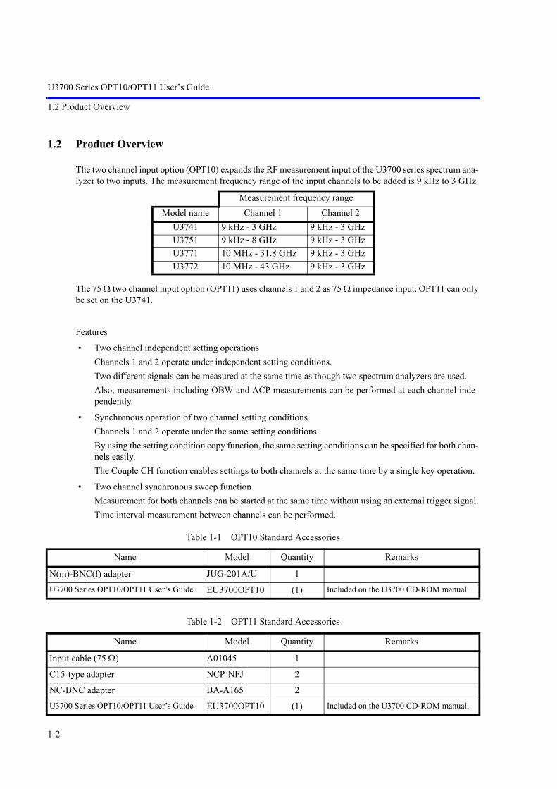
U3700 Series OPT10/OPT11 User’s Guide
1.2 Product Overview
1-2
1.2 Product Overview
The two channel input option (OPT10) expands the RF measurement input of the U3700 series spectrum ana-lyzer to two inputs. The measurement frequency range of the input channels to be added is 9 kHz to 3 GHz.
The 75 Ω two channel input option (OPT11) uses channels 1 and 2 as 75 Ω impedance input. OPT11 can onlybe set on the U3741.
Features
• Two channel independent setting operationsChannels 1 and 2 operate under independent setting conditions.Two different signals can be measured at the same time as though two spectrum analyzers are used.Also, measurements including OBW and ACP measurements can be performed at each channel inde-pendently.
• Synchronous operation of two channel setting conditionsChannels 1 and 2 operate under the same setting conditions.By using the setting condition copy function, the same setting conditions can be specified for both chan-nels easily.The Couple CH function enables settings to both channels at the same time by a single key operation.
• Two channel synchronous sweep functionMeasurement for both channels can be started at the same time without using an external trigger signal.Time interval measurement between channels can be performed.
Measurement frequency rangeModel name Channel 1 Channel 2
U3741 9 kHz - 3 GHz 9 kHz - 3 GHzU3751 9 kHz - 8 GHz 9 kHz - 3 GHzU3771 10 MHz - 31.8 GHz 9 kHz - 3 GHzU3772 10 MHz - 43 GHz 9 kHz - 3 GHz
Table 1-1 OPT10 Standard Accessories
Name Model Quantity Remarks
N(m)-BNC(f) adapter JUG-201A/U 1U3700 Series OPT10/OPT11 User’s Guide EU3700OPT10 (1) Included on the U3700 CD-ROM manual.
Table 1-2 OPT11 Standard Accessories
Name Model Quantity Remarks
Input cable (75 Ω) A01045 1
C15-type adapter NCP-NFJ 2
NC-BNC adapter BA-A165 2U3700 Series OPT10/OPT11 User’s Guide EU3700OPT10 (1) Included on the U3700 CD-ROM manual.

U3700 Series OPT10/OPT11 User’s Guide
2. INSTRUMENT CONFIGURATION AND BASIC OPERATIONS
2-1
2. INSTRUMENT CONFIGURATION AND BASIC OPERATIONS
This chapter describes the added or changed items of OPT10 and OPT11 on the panel, functions of each parton the screens, and basic operations of this instrument.
2.1 Panel and Screen Descriptions
This section describes the front panel, screen displays, and names and functions of each part.
2.1.1 Names and Functions of Each Part on the Front Panel
This section describes the names and functions of each part on the front panel.
Figure 2-1 Front Panel
1. Extended function key block The keys in this block set the extended functions. Specifies common settings regardless of channels.
2. Operation key block The keys in this block are used to change settings. Specifies settings for each channel independently.
3. Input and output connectors block The input and output connectors in this block are used for meas-urements.
4. Input connector lamp Indicates an active channel by illumination.
1 2
3
4

U3700 Series OPT10/OPT11 User’s Guide
2.1.1 Names and Functions of Each Part on the Front Panel
2-2
U3741 + OPT10/OPT11 Input and output connectors block
Figure 2-2 U3741 + OPT10/OPT11 Input and Output Connectors Block
1. TG OUTPUT connector Outputs the tracking generator signal. (Option)
2. CAL OUT connector Outputs the calibration signal.
3. RF INPUT 1 connector Inputs the signal to be measured.(Channel 1) Measurement frequency range: 9 kHz - 3 GHz
4. RF INPUT 2 connector Inputs the signal to be measured.(Channel 2) Measurement frequency range: 9 kHz - 3 GHz
CAUTION:
1. Do not apply an RF power or DC voltage that exceeds the limited value to the INPUT and OUT connectors.2. Be careful of static electricity. Internal circuit components such as the input attenuator and mixer may be
damaged.3. For the 75 Ω option (OPT11), input and output connectors are changed to 75 Ω type connectors.
If a 50 Ω cable or connector is connected to a 75 Ω connector, the center contact of the 75 Ω connector maybe damaged. Verify that cables and connectors, which are used, are 75 Ω type.
1 2 34
U3741: For the 75 Ω option (OPT11)

U3700 Series OPT10/OPT11 User’s Guide
2.1.1 Names and Functions of Each Part on the Front Panel
2-3
U3751 + OPT10 Input and output connectors block
Figure 2-3 U3751 + OPT10 Input and Output Connectors Block
1. CAL OUT connector Outputs the calibration signal.
2. RF INPUT 1 connector Inputs the signal to be measured.(Channel 1) Measurement frequency range: 9 kHz - 8 GHz
3. RF INPUT 2 connector Inputs the signal to be measured.(Channel 2) Measurement frequency range: 9 kHz - 3 GHz
CAUTION:
1. Do not apply an RF power or DC voltage that exceeds the limited value to the INPUT and OUT connectors.DC voltage tolerances of INPUT 1 and INPUT 2 are different.RF INPUT 1: ±15V DCRF INPUT 2: ±50V DC
2. Be careful of static electricity. Internal circuit components such as the input attenuator and mixer may bedamaged.
1 3 2

U3700 Series OPT10/OPT11 User’s Guide
2.1.1 Names and Functions of Each Part on the Front Panel
2-4
U3771/U3772 + OPT10 Input and output connectors block
Figure 2-4 U3771/U3772 + OPT10 Input and Output Connectors Block
1. CAL OUT connector Outputs the calibration signal.
2. RF INPUT 1 connector Inputs the signal to be measured.(Channel 1) Measurement frequency range:
10 MHz - 31.8 GHz (U3771)10 MHz - 43 GHz (U3772)
3. RF INPUT 2 connector Inputs the signal to be measured.(Channel 2) Measurement frequency range: 9 kHz - 3 GHz
CAUTION:
1. Do not apply an RF power or DC voltage that exceeds the limited value to the INPUT and OUT connectors.DC voltage tolerances of INPUT 1 and INPUT 2 are different.RF INPUT 1: ±25V DCRF INPUT 2: ±50V DC
2. Be careful of static electricity. Internal circuit components such as the input attenuator and mixer may bedamaged.
3. The precision microwave connector is used as the RF INPUT 1 connector.This connector is compatible with the K connector (K connector is a trademark of Anritsu Corporation.) andcan be connected to a common SMA connector.Be careful when handling this connector because the connector is delicate and is damaged easily.Use the included adapter (HE-A-PJ) if the connection and disconnection to this connector are performed fre-quently.
1 3 2

U3700 Series OPT10/OPT11 User’s Guide
2.1.2 Names and Functions of Each Part on the Screen
2-5
2.1.2 Names and Functions of Each Part on the Screen
This section describes the names and functions of the screens regarding OPT10.
Figure 2-5 Screen Display of DUAL CH ON 2 Screens
1. Operation mode When DUAL CH ON: Displays 2chSPA.When DUAL CH OFF: Nothing is displayed.
2. Active channel display Indicates the active channel, where settings can be changed, byusing the red rectangular box.
3. Active channel display Channel 1: CH1Channel 2: CH2Couple CH ON: CPL
123
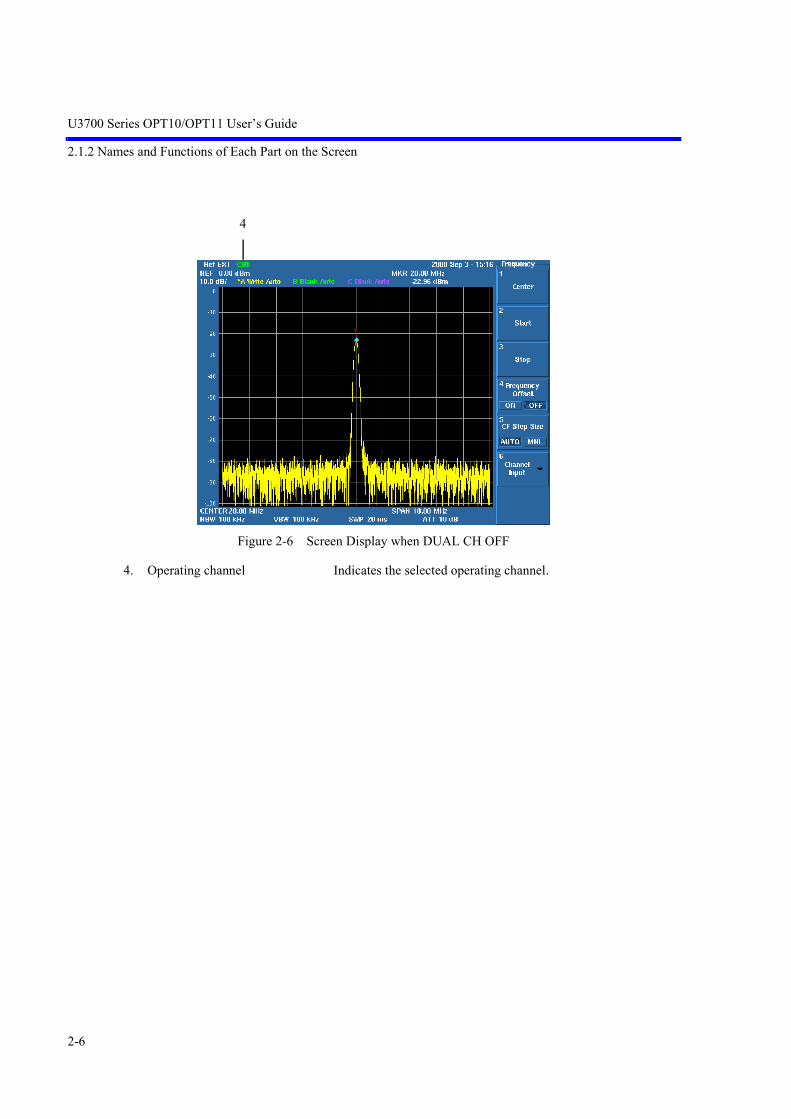
U3700 Series OPT10/OPT11 User’s Guide
2.1.2 Names and Functions of Each Part on the Screen
2-6
Figure 2-6 Screen Display when DUAL CH OFF
4. Operating channel Indicates the selected operating channel.
4

U3700 Series OPT10/OPT11 User’s Guide
2.2 Basic Operation
2-7
2.2 Basic Operation
This section describes the menu operations, data entry, and usage of the basic measurement functions.
Panel key operation
Extended function key: Specifies common settings regardless of channels.Operation key: Specifies settings for each channel independently.
As an exception, the USER key is common regardless of chan-nels.
Extended function key: Common setting Operation key: Independent setting

U3700 Series OPT10/OPT11 User’s Guide
2.2.1 Selecting Active Channel
2-8
2.2.1 Selecting Active Channel
The active channel is the target channel for changing settings.
There are two methods to select the active channel.
1. Use the SHIFT key + -(RF1) or SHIFT key + 0 (RF2).
• RF1 Activates channel 1.
• RF2 Activates channel 2.
• # Sets the Couple CH mode ON.Activates both channels 1 and 2.Key operations for FREQUENCY, SPAN, and CPL become enabled for both channel settings (except some functions).
2. Unit keys excluding Hz key is used.If a unit key is pressed when the setting input was complete, the active channels switch.Example: If the active channel is CH1, press FREQUENCY, 1, and GHz.
Set the center frequency of channel 1 to 1 GHz.Press GHz (one of the unit keys).The active channel is switched to channel 2.
Display regarding the active channel
1. Display the active channel on the top line of screenCH1: Channel 1 is selected as the active channel.CH2: Channel 2 is selected as the active channel.CPL On: This mode enables settings for both channels.
2. The red rectangular box surrounds the active channel window.Couple CH does not affect the rectangular display.
3. The front panel LED illuminates by corresponding to the active channel connec-tor.When Couple CH is ON, both LEDs illuminate.
SHIFT+Selecting channel 1Selecting channel 2
Couple CH ON
Unit keys excluding Hz key

U3700 Series OPT10/OPT11 User’s Guide
2.2.2 Switching Two Channel Display Modes
2-9
2.2.2 Switching Two Channel Display Modes
The display mode for two-channel measurement can be selected from the following two modes:
• 2 Screens Displays channel 1 in the upper window and channel 2 in the lower window.
• Full Screen Displays the specified channel full screen. The displayed channel becomes active.
The function setting remains the same by switching the 2 Screens ⇔ Full Screen display.
2.2.3 Synchronizing Channels 1 and 2
The Couple CH function can change settings for both channels by a single key operation.
Also by using the Setup copy function, the same channel setting conditions can be set.
CAUTION: When Setup copy is executed, data such as the ACP table, level correction table, and normalizationdata are copied with the setting conditions. The table content at the copied destination is overwritten to the blank table at the copy source. Also, there are some setting items which are not copied. After the copy, specify the setting again or obtain the correction again, if necessary.
2.2.4 Switching to Single Channel Mode
DUAL CH ON/OFF switches the operation between two channels and a single channel.
In the 2 channel mode, both channels perform measurement regardless of the display mode.
In the single channel mode, only the selected channel operates.
CAUTION:
1. The following functions are canceled by switching Dual ON ⇔ OFF (single channel).• MEAS function• VSWR measurement
2. In the single channel mode, an independent setting can be performed for each channel. Even if the channelis switched, the setting remains. (There are some common settings in channels 1 and 2 such as the Window setting.)

U3700 Series OPT10/OPT11 User’s Guide
2.2.5 Example of Operation
2-10
2.2.5 Example of Operation
Required equipment
This instrumentConversion adapter: N(m)-BNC(f)Input cable: BNC (m)-BNC (m)Signal generator: 20 MHz
Turn on the power and initialize the settings of this instrument.
Press SHIFT and SYSTEM(PRESET).Initial setting conditions are loaded.
Connecting the input signal
Connecting the signal which is used for measurement.
Attach the N(m)-BNC(f) adapter to the RF INPUT connector on the front panel.
Connect the RF INPUT 2 connector (CH2) and the CAL OUT connector by using thesupplied BNC (m)-BNC (m) cable.
Connect the RF INPUT 1 connector (CH1) to the signal generator.
Specify the setting so that a signal with a frequency of 20 MHz and a level of -20 dBmis output from the signal generator.
Signal generator

U3700 Series OPT10/OPT11 User’s Guide
2.2.5 Example of Operation
2-11
Setting measurement conditionsSetting the active channel
1. Press SHIFT and 0 (RF2).Channel 2 is selected.The red rectangular box surrounds the channel 2 window.Also, CH2 is displayed on the top line of the screen.
2. Press FREQUENCY, 2, 0, and MHz.The center frequency of channel 2 is set to 20 MHz.
3. Press SPAN, 1, 0, and MHz.The frequency span is set to 10 MHz.

U3700 Series OPT10/OPT11 User’s Guide
2.2.5 Example of Operation
2-12
Changing the two channel display mode
4. Press APPLI, Display, and Full Screen CH1.Display channel 1 full screen.Channel 1 becomes an active channel.
5. Press Full Screen CH2.Display channel 2 full screen.Channel 2 becomes an active channel.

U3700 Series OPT10/OPT11 User’s Guide
2.2.5 Example of Operation
2-13
6. Press 2 Screens.The screen returns to a two-screen display.
Synchronizing channels 1 and 2
7. Press APPLI, Setup copy, and CH2>>CH1.The setting conditions of channel 2 are copied to channel 1, and channels 1 and2 have the same settings.
8. Press Couple CH ON.The Couple CH mode turns ON and key operations are enabled for both channels.
NOTE: Only some functions of FREQUENCY, SPAN, and CPL keys are enabled. The AMPLITUDE key only allows an independent setting even if the CoupleCH mode is ON.

U3700 Series OPT10/OPT11 User’s Guide
2.2.5 Example of Operation
2-14
9. Press SPAN, 1, MHz, CPL, RBW, , FREQUENCY, and .Channel 1 and 2 settings are changed to the same setting.
10. Press AMPLITUDE, Ref Level, 4, 0, and GHz.The Ref Level of only channel 2 is changed to 40 dBm.

U3700 Series OPT10/OPT11 User’s Guide
2.2.5 Example of Operation
2-15
Switching to single channel mode
11. Press APPLI, Return, and Dual CH ON/OFF (OFF).Channel 2, which is the active channel, is displayed full screen.

U3700 Series OPT10/OPT11 User’s Guide
2.2.6 Note when Displaying 2 Screens
2-16
2.2.6 Note when Displaying 2 Screens
When a combination of the MEAS function and marker list is displayed at the same time, the result maynot be displayed correctly because of the display area.
If this occurs, use Full Screen as shown below.
Example: 5th order harmonic measurement byusing the Harmonics function
Display the maker list.The measurement window is compressed.
Enlarge the result display area in theFull Screen display.

U3700 Series OPT10/OPT11 User’s Guide
2.3 Calibration
2-17
2.3 Calibration
Correcting the measurement by using the calibration factor, which is acquired from the calibration, canincrease the measurement accuracy.
IMPORTANT: Perform calibration after allowing a warm up time of 5 minutes or more.
Required equipment
OPT10This instrumentConversion adapter: N(m)-BNC(f) Conversion adapter: BNC(f)-SMA(m) (U3771/U3772)Input cable: BNC(m)-BNC(m)
OPT11This instrument75 Ω NC-BNC adapter75 Ω input cable: BNC(m)-BNC(m)
Turning on the power
1. Verify that the AC power switch on the rear panel is set to OFF.
2. Connect the included power cable to the AC power connector on the rear panel.
CAUTION: To prevent damage, do not supply a voltage and frequency, whichexceed the specified range, to this instrument.
3. Connect the power cable to a power outlet.
4. Turn on the AC power switch on the rear panel.After turning on the AC power switch, wait for three seconds or more.
5. Turn on the power switch on the front panel.
NOTE: The display may be different depending on the status when the power was lastturned off.
CAUTION: Before turning the power on, remove the USB memory key. Otherwise,the system does not start.

U3700 Series OPT10/OPT11 User’s Guide
2.3 Calibration
2-18
Initializing the setting
Initializing the settings of this instrument.
6. Press SHIFT and SYSTEM(PRESET).Initial setting conditions are loaded.
Figure 2-7 Initial Setting Screen
Selecting the input connector
Select the input to perform the calibration.
Press SHIFT and - (RF1). RF INPUT 1 (channel 1) is selected.Press SHIFT and 0 (RF2).RF INPUT 2 (channel 2) is selected.
The calibration of either RF INPUT 1 or RF INPUT 2 can be performed first.
The following describes the procedure in which the calibration of RF INPUT 1 (channel 1) is performedfirst.
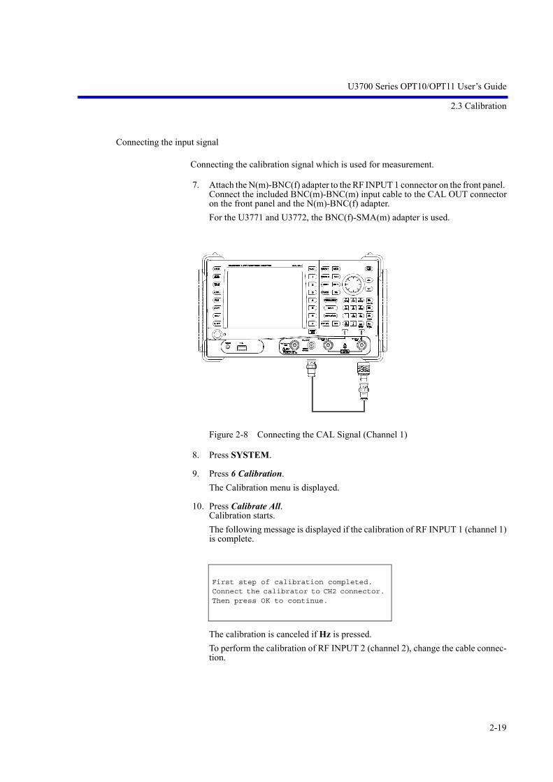
U3700 Series OPT10/OPT11 User’s Guide
2.3 Calibration
2-19
Connecting the input signal
Connecting the calibration signal which is used for measurement.
7. Attach the N(m)-BNC(f) adapter to the RF INPUT 1 connector on the front panel. Connect the included BNC(m)-BNC(m) input cable to the CAL OUT connectoron the front panel and the N(m)-BNC(f) adapter.For the U3771 and U3772, the BNC(f)-SMA(m) adapter is used.
Figure 2-8 Connecting the CAL Signal (Channel 1)
8. Press SYSTEM.
9. Press 6 Calibration.The Calibration menu is displayed.
10. Press Calibrate All.Calibration starts.The following message is displayed if the calibration of RF INPUT 1 (channel 1)is complete.
The calibration is canceled if Hz is pressed.To perform the calibration of RF INPUT 2 (channel 2), change the cable connec-tion.
First step of calibration completed. Connect the calibrator to CH2 connector. Then press OK to continue.

U3700 Series OPT10/OPT11 User’s Guide
2.3 Calibration
2-20
11. Attach the BNC(f)-SMA(m) adapter to the RF INPUT 2 connector on the frontpanel. Connect the included BNC(m)-BNC(m) input cable to the CAL OUT connectoron the front panel and the BNC(f)-SMA(m) adapter.
Figure 2-9 Connecting the CAL Signal (Channel 2)
12. Press and select OK. Press Hz to restart the calibration.
CAUTION: If an error is displayed in calibration, contact Advantest Instrument Call Center.

U3700 Series OPT10/OPT11 User’s Guide
2.4 Measurement Example
2-21
2.4 Measurement Example
2.4.1 W-CDMA Signal Channel Power Measurement and Adjacent Channel Leakage Power (ACP) Measurement
This section describes measurement of input and output signals of the amplifier by using the W-CDMAsignal.
Connecting the signal
CH2 Input CH1 Input
W-CDMA signal source1952.4 MHz
Amplifier
Input Output
Coupler

U3700 Series OPT10/OPT11 User’s Guide
2.4.1 W-CDMA Signal Channel Power Measurement and Adjacent Channel Leakage Power (ACP) Measurement
2-22
Operation
1. Press SHIFT and SYSTEM(PRESET).Initial setting conditions are loaded. Channel 1 is set to the active channel.
2. Press SHIFT and 0(RF2).Channel 2 is set to the active channel.
3. Press FREQUENCY, 1, 9, 5, 2, ., 4, MHz, SPAN, and 1, 0, MHz.Channel 2 is set as follows:Center frequency: 1952.4 MHzFrequency span: 10 MHz
4. Press MEAS1, Channel Power, Channel Width, 3, ., 8, 4, MHz, and ExecuteON/OFF(ON).The channel width is set to 3.84 MHz and the channel power measurement starts.The measurement result is displayed at the right side of the trace window.

U3700 Series OPT10/OPT11 User’s Guide
2.4.1 W-CDMA Signal Channel Power Measurement and Adjacent Channel Leakage Power (ACP) Measurement
2-23
5. Press SHIFT, and - (RF1).Channel 1 is set to the active channel.
6. Press FREQUENCY, 1, 9, 5, 2, ., 4, MHz, SPAN, and 2, 5, MHz.Channel 1 is set as follows:Center frequency: 1952.4 MHzFrequency span: 25 MHz
7. Press MEAS1, RETURN, ACP, and Channel Definition.The CS/BS table is displayed.The cursor is positioned at the Channel Space 1 setting text field.
8. Press 5 and MHz.Channel Space 1 is set to 5 MHz.The cursor moves to the Channel Bandwidth 1 setting text field.
9. Press 3, ., 8, 4, and MHz.Channel Bandwidth 1 is set to 3.84 MHz.The cursor moves to the Channel Space 2 setting text field.
10. Press 1, 0, and MHz.Channel Space 1 is set to 10 MHz.The cursor moves to the Channel Bandwidth 2 setting text field.
11. Press 3, ., 8, 4, and MHz.Channel Bandwidth 2 is set to 3.84 MHz.
12. Press RETURN.

U3700 Series OPT10/OPT11 User’s Guide
2.4.1 W-CDMA Signal Channel Power Measurement and Adjacent Channel Leakage Power (ACP) Measurement
2-24
13. Press Execute ON/OFF (ON).The ACP measurement starts.The measurement result is displayed at the right side of the trace window.
Displaying MEAS function
The measurement result of the MEAS function is simplified because it is displayedalong with the trace waveform.
In the Full Screen waveform display, the waveform in the two screens are simplyenlarged and displayed.
To display the measurement result without simplifying, perform measurement in DualCH OFF (single channel mode).
Displaying Dual CH ON Displaying Dual CH OFF

U3700 Series OPT10/OPT11 User’s Guide
2.4.2 Characteristics Evaluation of Frequency Converter
2-25
2.4.2 Characteristics Evaluation of Frequency Converter
This section describes measurement of a frequency response of a frequency converter such as a mixer orTV tuner, whose input and output frequencies differ. Channel 1 sets the frequency range by using a tracking generator as an input signal. Channel 2 observes the output signal of the converter.
The measurement target here is a down-converter module of a mixer + IF filter.RF frequency: 1900 MHzIF frequency: 182 MHz
CAUTION: The frequency converter enables measurement with an up/down-converter, however measurementscannot be performed when the relationship of the frequency is Lo - RF = IF.

U3700 Series OPT10/OPT11 User’s Guide
2.4.2 Characteristics Evaluation of Frequency Converter
2-26
Connecting the signal
Required setting condition
Set the frequency span, sweep time, and trigger source of channels 1 and 2 the same.
Functions used in this measurement
Synchronizes sweep of channels 1 and 2 by using the CH Sync function.
Operation
1. Press SHIFT and SYSTEM(PRESET).Initial setting conditions are loaded.Channel 1 is set to the active channel.
Mixer under testRF Input
RF Output
CH2 Input CH1 Input
Coupler
TG Output
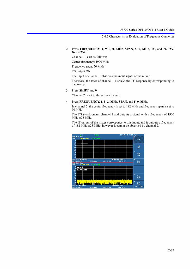
U3700 Series OPT10/OPT11 User’s Guide
2.4.2 Characteristics Evaluation of Frequency Converter
2-27
2. Press FREQUENCY, 1, 9, 0, 0, MHz, SPAN, 5, 0, MHz, TG, and TG ON/OFF(ON).Channel 1 is set as follows:Center frequency: 1900 MHzFrequency span: 50 MHzTG output ONThe input of channel 1 observes the input signal of the mixer.Therefore, the trace of channel 1 displays the TG response by corresponding tothe sweep.
3. Press SHIFT and 0.Channel 2 is set to the active channel.
4. Press FREQUENCY, 1, 8, 2, MHz, SPAN, and 5, 0, MHz.In channel 2, the center frequency is set to 182 MHz and frequency span is set to50 MHz.The TG synchronizes channel 1 and outputs a signal with a frequency of 1900MHz ±25 MHz.The IF output of the mixer corresponds to this input, and it outputs a frequencyof 182 MHz ±25 MHz, however it cannot be observed by channel 2.

U3700 Series OPT10/OPT11 User’s Guide
2.4.2 Characteristics Evaluation of Frequency Converter
2-28
5. Press TG and CH Sync ON/OFF(ON).Sweep of channels 1 and 2 is synchronized, and the frequency response of the fre-quency-converted mixer is displayed in the trace of channel 2.

U3700 Series OPT10/OPT11 User’s Guide
3. MENU MAP AND FUNCTION DESCRIPTION
3-1
Operation Key Pages Operation Key Pages
3. MENU MAP AND FUNCTION DESCRIPTION
This chapter describes the functions of the panel keys and soft keys in the items shown below.
Menu Index: This section can be used to refer to the keys in Chapter 3.
Menu Map: This section shows the menu configurations of the panel keys.
Restrictions: Describes the restriction of the two channel input option.
Functional Descriptions: This section describes the functions of the panel keys and soft keys.
3.1 Menu Index
2 Screens ................................................. 3-3APPLI ..................................................... 3-3Alternate IF ............................................. 3-5Alternate Video ....................................... 3-5CH Sync ON/OFF ................................... 3-7CH1>>CH2 ............................................. 3-3CH2>>CH1 ............................................. 3-3Couple CH ON/OFF ............................... 3-3, 3-4EXT CFG ................................................ 3-5Delta Mode ............................................. 3-6Display .................................................... 3-3Dual CH ON/OFF ................................... 3-3, 3-4Dual Delta ON/OFF ................................ 3-6Gated Sweep ........................................... 3-5Full Screen CH1 ...................................... 3-3Full Screen CH2 ...................................... 3-3MKR ....................................................... 3-6Math ........................................................ 3-6More 1/2 .................................................. 3-9Self Test .................................................. 3-9Self Test ALL ......................................... 3-9Self Test CH1 .......................................... 3-9Self Test CH2 .......................................... 3-9Setup Copy .............................................. 3-3Source ..................................................... 3-5Store ........................................................ 3-6TG ........................................................... 3-7TRACE ................................................... 3-6TRC→(A) ............................................... 3-6TRC→(B) ............................................... 3-6Trig Sync ON/OFF ................................. 3-5Trigger .................................................... 3-5

U3700 Series OPT10/OPT11 User’s Guide
3.2 Restrictions
3-2
3.2 Restrictions
In some functions of the two channel input option, there are some parts whose operations differ from theU3741 function which does not have optional settings.
Also, there are functions which cannot be used in both channels because of the hardware restrictions.
1. TraceIn Dual mode: Two traces, A and B, can be used.In Single mode: Three traces, A, B, and C can be used.
2. TriggerSetting the trigger levelThe level setting of the IF trigger is the same setting as channels 1 and 2. (The IF trigger level cannot be set independently.)The level setting of the EXT trigger is internally the same as the IF trigger. Note the level setting value when setting the IF trigger and the EXT trigger at the same time.
3. Zoom functionIn Dual mode: Zoom function cannot be used.In Single mode: The Zoom function can be used, but when the Zoom function is On, the MEAS func-
tion cannot be used.
4. Sound monitor functionThe sound demodulation function can use only channel 1.
5. TG (tracking generator) optionThe TG option corresponds to channel 1.
6. 21.4 MHz IF outputThe IF signal corresponds to channel 1.
7. GPIB commandR3131 and R3162 compatibility modes cannot be used.

U3700 Series OPT10/OPT11 User’s Guide
3.3 Functional Descriptions
3-3
3.3 Functional Descriptions
This section describes the functions of the panel keys and soft keys.
MEMO:
• indicates a panel key.• All other names are soft menus.
3.3.1 APPLI
Displays the APPLI menu
Display Displays the Display menu.
2 Screens Displays two screens in the upper and lower parts.
Upper screen: CH1
Lower screen: CH2
Full Screen CH1 Displays channel 1 on the entire screen.
The active channel is channel 1.
Full Screen CH2 Displays channel 2 on the entire screen.
The active channel is channel 2.
Setup Copy Displays the Sync Channel menu.
CH1>>CH2 Copies the setting condition of channel 1 to channel 2 and appliesit.
CH2>>CH1 Copies the setting condition of channel 2 to channel 1 and appliesit.
After the copy, the setting conditions and contents of the setting table for channels 1 and 2 are all the same.
CAUTION: If there is data such as a table that the user does notwant to change, save it to a USB memory beforecopying.
APPLI
DisplaySetup CopyCouple CH ON/OFFDual CH ON/OFF
2 ScreensFull Screen CH1Full Screen CH2
CH1>>CH2CH2>>CH1Couple CH ON/OFF

U3700 Series OPT10/OPT11 User’s Guide
3.3.1 APPLI
3-4
Couple CH ON/OFF ON: Couples and operates channels1 and 2. The key settings operate for both channels regardless ofthe active or non-active channel.
Coupled functions
FrequencyCenterStartStop
SPANSPANFull SpanZero SpanLast Span
CPLRBWVBWSweep TimeAll Auto
OFF: Cancels the coupling.
Couple CH ON/OFF ON: Couples and operates channels1 and 2. The key settings operate for both channels regardless ofthe active or non-active channel.
Coupled functions
FrequencyCenterStartStop
SPANSPANFull SpanZero SpanLast Span
CPLRBWVBWSweep TimeAll Auto
OFF: Cancels the coupling.
Dual CH ON/OFF ON: Operates in the 2CH mode.
OFF: Operates in the single channel mode.Only the active channel operates.

U3700 Series OPT10/OPT11 User’s Guide
3.3.2 EXT CFG
3-5
3.3.2 EXT CFG
Trigger Displays the Trigger menu.
Source Displays the Trig Source menu.
Alternate Video Selects the Video trigger signal of the other channel.
Alternate IF Selects the IF trigger signal of the other channel.
Trig Sync ON/OFF ON: When the trigger source of both channels is the same,sweep starts at the same time. When turning it ON, select the setting so that the triggersource of both channels is the same.When the sweep time of each channel is different, thesweep cycle corresponds to the slower channel.
OFF: Cancels the trigger sync function. Each channel performs an asynchronous sweep.
Gated Sweep
Source
Alternate IF Selects the IF trigger signal of the other channel.
EXT CFG
TriggerGated Sweep
SourceExt Trigger Level
LevelSlope NEG/POSDelayTrig Sync ON/OFF
Free RunVideoExternal
IFAlternate VideoAlternate IF
Gated Sweep ON/OFFSourceSlope NEG/POSGate Delay
Gate Width
External
IFAlternate IF

U3700 Series OPT10/OPT11 User’s Guide
3.3.3 TRACE
3-6
3.3.3 TRACE
Math
Store
TRC→(A) Stores the data of the active trace to trace A memory of the otherchannel.
TRC→(B) Stores the data of the active trace to trace B memory of the otherchannel.
3.3.4 MKR
Delta Mode
Dual Delta ON/OFF Switches the delta marker display function between both channelsON and OFF.
ON: Positions the reference marker in the other channel, anddisplays the relative value (frequency and level) of theactive channel to the normal marker in the marker area.
OFF: Deletes the delta marker display.
SubtractStore TRC→A
TRC→BTRC→CTRC→(A)TRC→(B)Trace A/B/C
TRACE
Math
MKR
Delta Delta ON/OFFRef ObjectFixed Mkr ON/OFF
1/Delta Mkr ON/OFFDual Delta ON/OFF

U3700 Series OPT10/OPT11 User’s Guide
3.3.5 TG
3-7
3.3.5 TG
CH Sync ON/OFF ON: Sets the channel synchronous function ON. Synchronizes sweep of channels 1 and 2.
OFF: Cancels the channel synchronous function.CH Sync is a function which performs sweep synchronizing with channels 1 and 2.
By using CH Sync, the tracking generator, which normally corresponds to channel 1, can also be used withchannel 2.
To use CH Sync, set the frequency span, sweep time, and trigger source of channels 1 and 2 the same.
TG
TG ON/OFF
TG LevelTG Level Offset ON/OFFTG Freq. Offset ON/OFFCH Sync ON/OFFNormalizeReference Line ON/OFF

U3700 Series OPT10/OPT11 User’s Guide
3.3.5 TG
3-8
Example: Input the TG output to channels 1 and 2 at the same time.
CH Sync ON: TG responds to both channels 1 and 2.
CH Sync OFF: TG responds to channel 1. Because channel 2 performs an asynchronous sweep with channel1, there is not any response in channel 2.
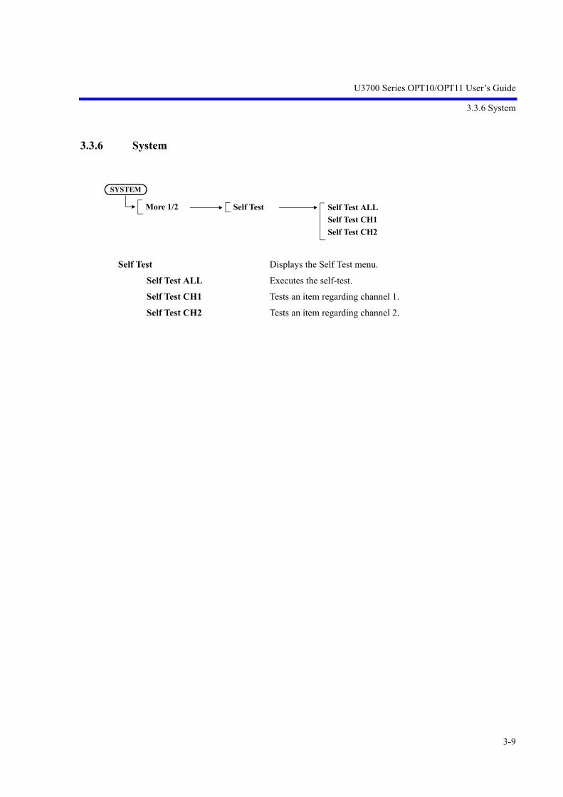
U3700 Series OPT10/OPT11 User’s Guide
3.3.6 System
3-9
3.3.6 System
Self Test Displays the Self Test menu.
Self Test ALL Executes the self-test.
Self Test CH1 Tests an item regarding channel 1.
Self Test CH2 Tests an item regarding channel 2.
Self Test Self Test ALLSelf Test CH1Self Test CH2
SYSTEM
More 1/2


U3700 Series OPT10/OPT11 User’s Guide
4. OVERVIEW OF REMOTE CONTROL
4-1
4. OVERVIEW OF REMOTE CONTROL
This chapter describes the added and changed items in OPT10 regarding the remote control system.
4.1 Status Byte
Statuses regarding channel 2 are allocated from bit 11 to bit 15 of the standard operation status register.
Figure 4-1 Status Registers
Standard operation status register
Standard event
Status byte register
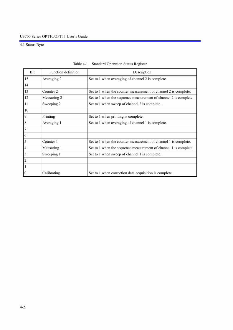
U3700 Series OPT10/OPT11 User’s Guide
4.1 Status Byte
4-2
Table 4-1 Standard Operation Status Register
Bit Function definition Description
15 Averaging 2 Set to 1 when averaging of channel 2 is complete.1413 Counter 2 Set to 1 when the counter measurement of channel 2 is complete.12 Measuring 2 Set to 1 when the sequence measurement of channel 2 is complete.11 Sweeping 2 Set to 1 when sweep of channel 2 is complete.109 Printing Set to 1 when printing is complete.8 Averaging 1 Set to 1 when averaging of channel 1 is complete.765 Counter 1 Set to 1 when the counter measurement of channel 1 is complete.4 Measuring 1 Set to 1 when the sequence measurement of channel 1 is complete.3 Sweeping 1 Set to 1 when sweep of channel 1 is complete.210 Calibrating Set to 1 when correction data acquisition is complete.

U3700 Series OPT10/OPT11 User’s Guide
4.2 Operation of TS command at Dual CH
4-3
4.2 Operation of TS command at Dual CH
TS (Take Sweep)
When the TS command is executed, the specified channel becomes a single sweepmode and starts sweep.
The GPIB bus maintains the hold state during the sweep, and the next command waitsfor the completion of the sweep and then it is executed
Operation
1. TSStarts sweep of the active channel, and holds the GPIB bus until the sweep of theactive channel has been complete.
GPIB state
CH1 (Active CH)SWEEP
Note: The non-active CH does not relate to TS.
HOLD
TS execution BUS release
CH2SWEEP

U3700 Series OPT10/OPT11 User’s Guide
4.2 Operation of TS command at Dual CH
4-4
2. TSMStarts sweep of channels 1 and 2 at the same time, and holds the GPIB bus untilthe sweep of both channels has been complete.
3. TSSStarts sweep of channels 1 and 2 at the same time, and holds the GPIB bus untileither channel, whichever completes the sweep faster, completes the sweep.
HOLD
CH1SWEEP
CH2SWEEP
GPIB state
TS execution BUS release
HOLD
CH1SWEEP
CH2SWEEP
GPIB state
TS execution BUS release

U3700 Series OPT10/OPT11 User’s Guide
4.3 GPIB Remote Programming
4-5
4.3 GPIB Remote Programming
This section shows the AT command list for each OPT10 function:
• Command codeThe command code “*” indicates a function that numeric or character strings data follows after the code.Data in [ ] can be omitted.
• Output format
• A comma “,” indicates that two or more data items are output.
• ON or OFF indicates that 1 or 0 is output.
• Frequency is output in Hz and time is output in sec.
• Level data is output in the currently set display unit.
4.4 AT Command Code List
4.4.1 APPLI (Mode setting)
FunctionCommand (EXE, SET) Query (GET)
Code Argument Format Code Output Format
Dual Channel DUAL* ON|OFF DUAL? 0 = OFF1 = ON
Active Channel Select ACTCH* CH1|CH2 ACTCH? 1 = CH12 = CH2
Couple Channel CPLCH* ON|OFF CPLCH? 0 = OFF1 = ON
Display mode DISP* SPLIT|FULL1|FULL2 DISP? 0 = SPLIT1 = FULL12 = FULL2
Copy Settings -- -- --Copy CH1 → CH2 CP1TO2Copy CH2 → CH1 CP2TO1

U3700 Series OPT10/OPT11 User’s Guide
4.4.2 Sweep
4-6
4.4.2 Sweep
FunctionCommand (EXE, SET) Query (GET)
Code Argument Format Code Output Format
Sweep Time SW|ST* Time SW?|ST? TimeSweep Auto AS[*] [ON]|OFF AS? 0 = OFF (manual)
1 = ON (auto)Sweep Mode SWM? 0 = Single
1 = NormalSweep Mode Normal
active Ch SN|CONTS -- -- --both Ch SNALL|CONTSALL -- -- --Ch1 SN1|CONTS1 -- -- --Ch2 SN2|CONTS2 -- -- --
Sweep Mode Single -- -- --active Ch SI|SNGLS -- -- --both Ch SIALL|SNGLSALL -- -- --Ch1 SI1|SINGLS1 -- -- --Ch2 SI2|SINGLS2 -- -- --
Take Sweep -- -- --active Ch TS -- -- --both Ch (*1) TSM -- -- --both Ch (*2) TSS -- -- --
Sweep Start / Stop -- -- --active Ch SR -- -- --both Ch SRALL -- -- --Ch1 SR1 -- -- --Ch2 SR2 -- -- --
Gated Sweep Mode GTSWP* ON|OFF GTSWP? 0 = OFF1 = ON
Gate Source GTSRC* EXT|IF|XIF GTSRC? 2 = EXT3 = IF5 = XIF
Gate Slope GTSLP* (FALL|NEG|-)| (RISE|POS|+)
GTSLP? 0= RISE|POS|+1= FALL|NEG|-
Gate Delay GTPOS* Time GTPOS? TimeGate Width GTWID* Time GTWID? Time(*1) Completed when both channels are “Sweep end.”(*2) Completed when either channel is “Sweep end.”

U3700 Series OPT10/OPT11 User’s Guide
4.4.3 Trigger
4-7
4.4.3 Trigger
4.4.4 Trace
FunctionCommand (EXE, SET) Query (GET)
Code Argument Format Code Output Format
Trigger Mode TRGSRC* FREE|IF|EXT|VIDEO|XVIDEO|XIF
TRGSRC? 0 = FREE1 = TRG_VIDEO2 = TRG_EXT3 = TRG_IF4 = XVIDEO5 = XIF
Video or IF Trigger Level TRGLVL* Level TRGLVL? LevelExternal Trigger Level TRGTTLLVL* Voltage TRGTTLLVL? VoltageTrigger Slope TRGSLP* (FALL|NEG|-)|
(RISE|POS|+)TRGSLP? 0 = RISE|POS|+
1 = FALL|NEG|-Trigger Delay TRGDLY* Time TRGDLY? TimeTrigger Sync ON/OFF SYNCTRIG ON|OFF SYNCTRIG? 0 = OFF
1 = ON
FunctionCommand (EXE, SET) Query (GET)
Code Argument Format Code Output Format
Math : Trace Store (Current trace → trace n)
STORE* TRA|TRB|TRC
→ trace n of Non-active channel
STORE* TRXA|TRXB
Trace Data Binary OutChannel1 TraceAChannel2 TraceAChannel1 TraceBChannel2 TraceBChannel1 TraceCChannel2 TraceC
-- --TBA1?TBA2?TBB1?TBB2?TBC1?TBC2?
Depends on FORM commands

U3700 Series OPT10/OPT11 User’s Guide
4.4.5 Marker
4-8
4.4.5 Marker
4.4.6 TG
4.4.7 Save/Recall
FunctionCommand (EXE, SET) Query (GET)
Code Argument Format Code Output Format
Dual Delta Mode MKDD* ON|OFF MKDD? 0 = OFF1 = ON
FunctionCommand (EXE, SET) Query (GET)
Code Argument Format Code Output Format
CH Sync ON/OFF SYNCCH ON|OFF SYNCCH? 0 = OFF1 = ON
FunctionCommand (EXE, SET) Query (GET)
Code Argument Format Code Output Format
Save Normalize Context A Trace A
SVNRM1A ON|OFF SVNRM1A? 0 = OFF1 = ON
Save Normalize Context A Trace B
SVNRM1B ON|OFF SVNRM1B? 0 = OFF1 = ON
Save Normalize Context A Trace C
SVNRM1C ON|OFF SVNRM1C? 0 = OFF1 = ON
Save Normalize Context B Trace A
SVNRM2A ON|OFF SVNRM2A? 0 = OFF1 = ON
Save Normalize Context B Trace B
SVNRM2B ON|OFF SVNRM2B? 0 = OFF1 = ON

U3700 Series OPT10/OPT11 User’s Guide
4.4.8 Calibration
4-9
4.4.8 Calibration
4.4.9 GPIB
FunctionCommand (EXE, SET) Query (GET)
Code Argument Format Code Output Format
Calibration All CLALL[*] [RFC1]|RFC2 -- --Total Gain Calibration CLGAIN[*] [RFC1]|RFC2 CLGAIN
[RFC1]|RFC2?Integer0 = OK>0 = Warning<0 = Error
RBW Calibration CLRBW[*] [RFC1]|RFC2 CLRBW[RFC1]|RFC2?
Integer0 = OK>0 = Warning<0 = Error
PBW Calibration CLPBW[*] [RFC1]|RFC2 CLPBW[RFC1]|RFC2?
Integer0 = OK>0 = Warning<0 = Error
ATT step Calibration CLATT[*] [RFC1]|RFC2 CLATT[RFC1]|RFC2?
Integer0 = OK>0 = Warning<0 = Error
FunctionCommand (EXE, SET) Query (GET)
Code Argument Format Code Output Format
Access Channel CH1 X1 -- -- --Access Channel CH2 X2 -- -- --

U3700 Series OPT10/OPT11 User’s Guide
4.5 Example Program for Remote Control
4-10
4.5 Example Program for Remote Control
This section describes an example program for remote control.
For more information on the GPIB bus controller and reading the Visual Basic GPIB control library, refer tomanuals of the main unit.
4.5.1 Access Channel Example Program
To set or read data to or from channels 1 and 2 by remote control, an active channel must be set.
When setting only one command for the inactive channel, it can be done with two commands of "X2" and"command" by using the Access Channel command.
The channel setting with the Access Channel command is applied to only one command that follows "X1"or "X2".
Example: To read the peak frequency of channels 1 and 2:
Dim Rdbuff1 as String, Rdbuff2 as StringCall ibdev(0,8,0,T10S,1,0,SPA) 'GPIB device initializationCall ibclr(spa) 'Device clearCall ibwrt(spa, "IP") 'presetCall ibwrt(spa, "TSM") 'Sweeps both channels once
Call ibwrt(spa, "PS") 'Peak search for channel 1Call ibwrt(spa, "X2;PS") 'Peak search for channel 2Rdbuff = Space(30) 'Allocates 30 bytes to the buffer areaCall ibwrt(spa, "MF?") 'Reads the marker frequency of channel 1Call ibrd(spa, Rdbuff1) 'Reads dataCall ibwrt(spa, "X2;MF?") 'Reads the marker frequency of channel 2Call ibrd(spa, Rdbuff2) 'Reads data
GPIB code Description
X1 Only one subsequent command is set to channel 1.X2 Only one subsequent command is set to channel 2.

U3700 Series OPT10/OPT11 User’s Guide
4.6 SCPI Command Code List
4-11
4.6 SCPI Command Code List
4.6.1 APPLI (Mode setting)
Function description SCPI command Parameter Query reply
Dual Channel :DISPlay:DUAL @1$1= :DISPlay:DUAL?
ON|OFF 0=OFF1=ON
Active Channel Select :DISPlay:ACT @1$1= :DISPlay:ACT?
CH1|CH2 CH1CH2
Couple Channel :SOURce:COUPle @1$1=: SOURce:COUPle?
ON|OFF 0=OFF1=ON
Display Mode :DISPlay:MODE @1$1=:DISPlay:MODE?
SPLIT|FULL1|FULL2 SPLITFULL1FULL2
Copy Settings :COPY:CHANnel @1,@2(*1)
Channel Index,Channel Index
--
(*1) @1: Source@2: Destination
Channel Index1|21 = Ch 12 = Ch 2

U3700 Series OPT10/OPT11 User’s Guide
4.6.2 Sweep
4-12
4.6.2 Sweep
4.6.3 Trigger
Function description SCPI command Parameter Query reply
Sweep Mode Normal/Single
Set CH1/CH2 :INITiate#1:CONT @1$1= :INITiate#1:CONT?
Channel IndexON|OFF
0 = OFF1 = ON
active Ch :INITiate:CONT @1 ON|OFFboth Ch :INITiate:MCONT @1 ON|OFF
Take Sweepactive Ch :INITiate:TS -- --both Ch (*1) :INITiate:TSMboth Ch (*2) :INITiate:TSS
Sweep Start / StopSet CH1/CH2 :INITiate#1:RESTart Channel Index --active Ch :INITiate:RESTart
(*1) Completed when both channels are “Sweep end.”(*2) Completed when either channel is “Sweep end.”
Channel Index1|2 1 = Ch 1 2 = Ch 2When omitted = Active Channel
Function description SCPI command Parameter Query reply
Trigger Mode :TRIGer#1[:SEQuence]:SOURce@2$1=:TRIGer#1[:SEQuence]:SOURce?
Channel index,IMMediate|IF|VIDeo|EXT|XVID|XIF
IMM|IF|VID|EXT|XVID|XIF
Trigger Sync ON/OFF :TRIGer[:SEQuence]:SYNChronize: @1$1=:TRIGer[:SEQuence]:SYNChronize?
ON|OFF 0 = OFF1 = ON
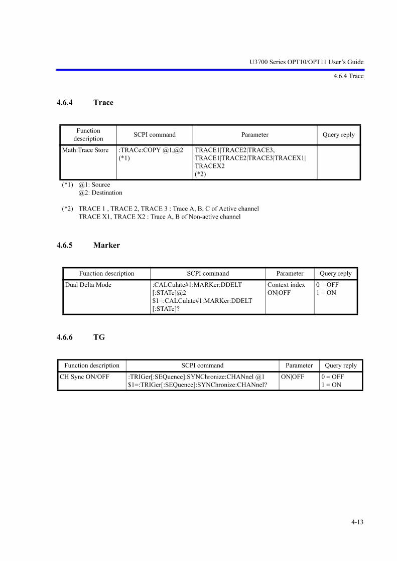
U3700 Series OPT10/OPT11 User’s Guide
4.6.4 Trace
4-13
4.6.4 Trace
4.6.5 Marker
4.6.6 TG
Function description SCPI command Parameter Query reply
Math:Trace Store :TRACe:COPY @1,@2(*1)
TRACE1|TRACE2|TRACE3,TRACE1|TRACE2|TRACE3|TRACEX1|TRACEX2(*2)
(*1) @1: Source@2: Destination
(*2) TRACE 1 , TRACE 2, TRACE 3 : Trace A, B, C of Active channelTRACE X1, TRACE X2 : Trace A, B of Non-active channel
Function description SCPI command Parameter Query reply
Dual Delta Mode :CALCulate#1:MARKer:DDELT[:STATe]@2$1=:CALCulate#1:MARKer:DDELT[:STATe]?
Context indexON|OFF
0 = OFF1 = ON
Function description SCPI command Parameter Query reply
CH Sync ON/OFF :TRIGer[:SEQuence]:SYNChronize:CHANnel @1$1=:TRIGer[:SEQuence]:SYNChronize:CHANnel?
ON|OFF 0 = OFF1 = ON


U3700 Series OPT10/OPT11 User’s Guide
5. SPECIFICATIONS
5-1
5. SPECIFICATIONS
5.1 Option 10 2-Channel Input
• Differences from U3741/U3751 input output standard specifications
• Differences from U3771/U3772 standard specifications
Item DescriptionFrequency Conforms to the U3741 standard specifications.
Applied to RF INPUT 2 (channel 2)SweepAmplitude rangeAmplitude accuracyDynamic range
Item DescriptionCrosstalk between input channels < -90 dBc (Input level -10 dBm, Input attenuator 0 dB)RF input 2
Connector N type femaleImpedance 50 Ω (nom.)VSWR <1.5 : 1 Input attenuator > 10 dB
External trigger input Can be selected as the trigger input of RF input 2 when OPT10 is installed. The input connector is a single line only.
21.4 MHz IF output When OPT10 is installed, it is only the IF output which corresponds to RF input 1.
Item DescriptionFrequency range [RF INPUT 1] 10 MHz - 31.8 GHz (U3771)
10 MHz - 43 GHz (U3772)Crosstalk between input channels < -90 dBc (Input level -10 dBm, Input attenuator 0 dB)RF input 1
Connector K type femaleImpedance 50 Ω (nom.)VSWR 1.7 : 1 (typ.) Band 0 Input attenuator ≥ 10 dB
2.0 : 1 (typ.) Band 1, Band 2, Band 3 Input attenuator ≥ 10 dB2.5 : 1 (typ.) Band 4 Input attenuator ≥ 10 dB
RF input 2Connector N type femaleImpedance 50 Ω (nom.)VSWR <1.5 : 1 Input attenuator > 10 dB
External trigger input Can be selected as the trigger input of RF input 2 when OPT10 is installed. The input connector is a single line only.
21.4 MHz IF output When OPT10 is installed, it is only the IF output which corresponds to RF input 1.

U3700 Series OPT10/OPT11 User’s Guide
5.2 Option 11 75 Ω 2-Channel Input (Can be Installed only in the U3741)
5-2
5.2 Option 11 75 Ω 2-Channel Input (Can be Installed only in the U3741)
• Difference with the standard specifications
Item DescriptionFrequency Conforms to the specifications given when U3741 is equipped with OPT15.SweepAmplitude rangeAmplitude accuracyDynamic range
Item DescriptionCrosstalk between input channels < -90 dBc (Input level -10 dBm, Input attenuator 0 dB)RF input 2
Connector N type femaleImpedance 75 Ω (nom.)VSWR <1.6 : 1 Input attenuator > 10 dB
External trigger input Can be selected as the trigger input of RF input 2 when OPT11 is installed. The input connector is a single line only.
21.4 MHz IF output When OPT11 is installed, it is only the IF output which corresponds to RF input 1.

U3700 Series OPT10/OPT11 User’s Guide
6. LIST OF ERROR MESSAGES
6-1
6. LIST OF ERROR MESSAGES
This chapter describes error messages regarding OPT10 and OPT11.
Error code Type Displayed Message Description of Message
0/33 WARNING CH Sync has been turned off. CH Sync was cancelled because the span, sweep time, or trigger source setting was changed when CH Sync was ON.
0/34 WARNING This functionality is not allowed if the SPAN, SWP, or TRG are not same on CH1 and CH2.
CH Sync cannot be set to ON because the span, sweep time, or trigger source set-ting for both channels differ.Match the settings of the span and sweep time.


U3700 Series OPT10/OPT11 User’s Guide
ALPHABETICAL INDEX
I-1
[Numerics]2 Screens ................................................. 3-3
[A]Access Channel Example Program ......... 4-10Alternate IF ............................................. 3-5Alternate Video ....................................... 3-5APPLI ..................................................... 3-3APPLI (Mode setting) ............................. 4-5, 4-11AT Command Code List ......................... 4-5
[B]Basic Operation ....................................... 2-7BASIC OPERATIONS ........................... 2-1
[C]Calibration .............................................. 2-17, 4-9CH Sync ON/OFF ................................... 3-7CH1>>CH2 ............................................. 3-3CH2>>CH1 ............................................. 3-3Characteristics Evaluation of Frequency Converter ............................... 2-25Contents of This Manual ......................... 1-1Couple CH ON/OFF ............................... 3-3, 3-4
[D]Delta Mode ............................................. 3-6Display .................................................... 3-3Dual CH ON/OFF ................................... 3-3, 3-4Dual Delta ON/OFF ................................ 3-6
[E]Example of Operation ............................. 2-10Example Program for Remote Control ... 4-10EXT CFG ................................................ 3-5
[F]Full Screen CH1 ...................................... 3-3Full Screen CH2 ...................................... 3-3FUNCTION DESCRIPTION ................. 3-1Functional Descriptions .......................... 3-3
[G]Gated Sweep ........................................... 3-5GPIB ....................................................... 4-9GPIB Remote Programming ................... 4-5
[ I ]INSTRUMENT CONFIGURATION ..... 2-1INTRODUCTION .................................. 1-1
[L]LIST OF ERROR MESSAGES .............. 6-1
[M]Marker ..................................................... 4-8, 4-13Math ........................................................ 3-6Measurement Example ........................... 2-21Menu Index ............................................. 3-1MENU MAP ........................................... 3-1MKR ....................................................... 3-6More 1/2 .................................................. 3-9
[N]Names and Functions of Each Part on the Front Panel ................................... 2-1Names and Functions of Each Part on the Screen ........................................... 2-5Note when Displaying 2 Screens ............ 2-16
[O]Operation of TS command at Dual CH .. 4-3Option 10 2-Channel Input ..................... 5-1Option 11 75 Ω 2-Channel Input (Can be Installed only in the U3741) ...... 5-2OVERVIEW OF REMOTE CONTROL 4-1
[P]Panel and Screen Descriptions ................ 2-1Product Overview ................................... 1-2
[R]Restrictions ............................................. 3-2
[S]Save/Recall ............................................. 4-8SCPI Command Code List ...................... 4-11Selecting Active Channel ........................ 2-8Self Test .................................................. 3-9Self Test ALL ......................................... 3-9Self Test CH1 .......................................... 3-9Self Test CH2 .......................................... 3-9Setup Copy .............................................. 3-3Source ..................................................... 3-5SPECIFICATIONS ................................. 5-1
ALPHABETICAL INDEX ALPHABETICAL INDEX

U3700 Series OPT10/OPT11 User’s Guide
Alphabetical Index
I-2
Status Byte .............................................. 4-1Store ........................................................ 3-6Sweep ...................................................... 4-6, 4-12Switching to Single Channel Mode ........ 2-9Switching Two Channel Display Modes 2-9Synchronizing Channels 1 and 2 ............ 2-9System ..................................................... 3-9
[T]TG ........................................................... 3-7, 4-8,
4-13TRACE ................................................... 3-6Trace ....................................................... 4-7, 4-13TRC→(A) ............................................... 3-6TRC→(B) ............................................... 3-6Trig Sync ON/OFF ................................. 3-5Trigger .................................................... 3-5, 4-7,
4-12
[W]W-CDMA Signal Channel Power Measurement and Adjacent Channel Leakage Power (ACP) Measurement ............................... 2-21

MANUAL NUMBER
CPrinted in Japan
ADVANTEST CORPORATIONAll rights reserved.
U3700 Series OPT53/OPT54/OPT55/OPT56
Time Domain Analysis OptionUser’s Guide
FOE-8440269C00
First printing October 10, 2008
Applicable ModelsU3741U3751U3771U3772
2008
Cover


U3700 Series OPT53/OPT54/OPT55/OPT56 User’s Guide
C-1
TABLE OF CONTENTS
1. INTRODUCTION ....................................................................................... 1-11.1 Contents of This Manual ................................................................................... 1-11.2 Product Overview .............................................................................................. 1-21.3 Conventions of Notation Used in This Document ............................................ 1-2
2. INSTRUMENT CONFIGURATION AND BASIC OPERATIONS 2-12.1 Names and Functions of Each Part on Screen .................................................. 2-12.1.1 Freq-Time, Phase-Time, Power-Time, or IQ-Time Display Screen .......... 2-12.1.2 Partial FFT Display Screen ........................................................................ 2-22.1.3 OPT54 2-channnel Display Window .......................................................... 2-32.2 Operating Method ............................................................................................. 2-42.2.1 Capturing I/Q Waveforms of RF Signal ..................................................... 2-52.2.1.1 Setting Center Frequency, Reference Level, and Sweep Mode ................. 2-52.2.1.2 Setting Waveform Capture Time and Capture Bandwidth ......................... 2-52.2.1.3 Starting and Stopping RF Signal Capture .................................................. 2-52.2.2 Analyzing RF Signal .................................................................................. 2-62.2.2.1 Freq-Time Analysis .................................................................................... 2-62.2.2.2 Phase-Time Analysis .................................................................................. 2-72.2.2.3 Power-Time Analysis ................................................................................. 2-82.2.2.4 IQ-Time Analysis ....................................................................................... 2-92.2.2.5 Partial FFT Analysis ................................................................................... 2-102.2.2.6 Freq-Time Analysis Using Position View Function .................................. 2-122.2.2.7 Two-Type Simultaneous Analysises Using Dual Meas Function
(Freq-Time and Phase-Time) ..................................................................... 2-142.3 OPT55 Pulse Modulation Signal Measurement Example ................................. 2-162.4 2-Channel Time Domain Analysis Option (OPT54/OPT56) ............................ 2-192.4.1 Main Basic Operations with 2-Channel Specifications .............................. 2-192.4.2 Example of Four-Value FSK Signal Analysis ............................................ 2-20
3. MENU MAP AND FUNCTION DESCRIPTION .............................. 3-13.1 Functional Descriptions .................................................................................... 3-13.1.1 Time Domain .............................................................................................. 3-13.1.2 MKR→ ....................................................................................................... 3−9
4. OVERVIEW OF REMOTE CONTROL ............................................... 4-14.1 GPIB Remote Programming ............................................................................. 4-14.2 AT Command Code List ................................................................................... 4-14.3 I/Q Data Output ................................................................................................. 4-3
5. SPECIFICATIONS ...................................................................................... 5-15.1 Option 53, Option 54 Time Domain Analysis Option ...................................... 5-15.2 Option 55, Option 56 Time Domain Analysis Option ...................................... 5-1
TABLE OF CONTENTS

U3700 Series OPT53/OPT54/OPT55/OPT56 User’s Guide
Table of Contents
C-2
6. UNCAL MESSAGE, LIST OF ERROR MESSAGES, AND RESTRICTIONS .............................................................................. 6-1
6.1 How to Delete UNCAL Message for Partial FFT Analysis .............................. 6-16.2 List Of Error Messages ..................................................................................... 6-26.3 Restrictions ........................................................................................................ 6-26.3.1 Restrictions on Key Operation during Time Domain Analysis Function Use 6-26.3.2 Restrictions for Trace Data Capture ........................................................... 6-2
ALPHABETICAL INDEX ..................................................................................... I-1

T-1
U3700 Series OPT53/OPT54/OPT55/OPT56 User’s Guide
LIST OF TABLES
No. Title Page
3-1 OPT53/OPT54 Capture BW Setting Value and Partial FFT Frequency Resolution ........ 3-53-2 OPT55/OPT56 Capture BW Setting Value and Partial FFT Frequency Resolution ........ 3-53-3 OPT53/OPT54 Capture BW Setting Value and Capture Time Maximum Value ............ 3-63-4 OPT55/OPT56 Capture BW Setting Value and Capture Time Maximum Value ............ 3-6


U3700 Series OPT53/OPT54/OPT55/OPT56 User’s Guide
1. INTRODUCTION
1-1
1. INTRODUCTION
This chapter describes the content of this manual and the product overview of the U3700 series spectrum ana-lyzer time domain analysis option (OPT53/OPT54/OPT55/OPT56) to help the user get the most out of thisguide.
For more information on the basic descriptions, refer to “U3700 Series User’s Guide.”
1.1 Contents of This Manual
The contents of each chapter are as follows:
CHAPTER 1. INTRODUCTION This chapter describes the contents of this manual and the product overview.
CHAPTER 2. INSTRUMENT CONFIGURA-TION AND BASIC OPERATIONS
This chapter describes the functions and operating methods of option with measurement examples.
CHAPTER 3. MENU MAP AND FUNCTION DESCRIPTION
This chapter describes the menu structure and functions of soft keys.
CHAPTER 4. OVERVIEW OF REMOTE CON-TROL
This chapter describes commands in order of functions for the added and changed items in option.
CHAPTER 5. SPECIFICATIONS This chapter describes option specifications.
CHAPTER 6. UNCAL MESSAGE, LIST OF ERROR MESSAGES, AND RESTRICTIONS
This chapter describes error messages and restrictions related to option.

U3700 Series OPT53/OPT54/OPT55/OPT56 User’s Guide
1.2 Product Overview
1-2
1.2 Product Overview
The time domain analysis options, OPT53, OPT54, OPT55, and OPT56, add a function, which captures andanalyzes changes of RF signal characteristics with time, to the U3700 series spectrum analyzer.
OPT53 and OPT55: Option for single channel input.
OPT54 and OPT56: Option for 2-channel input. The time domain analysis function is added to both chan-nels 1 and 2.
Features
• It performs quadrature separation for an RF signal and captures it as time domain I/Q waveforms.OPT53/OPT54
Measurement bandwidth (BW) 100 Hz to 3 MHz (1 to 3 steps)Number of I/Q waveform record samples 1 M Samples (I/Q)I/Q sampling rate 713 Hz (BW 100 Hz) to 21.4 MHz (BW 3 MHz) I/Q waveform record time 49 msec (BW 3 MHz) to 1000 sec (BW 100 Hz)
OPT55/OPT56Measurement bandwidth (BW) 100 Hz to 30 MHz (1 to 3 steps), 40 MHzNumber of I/Q waveform record samples 8 M Samples (I/Q)I/Q sampling rate 500 Hz (BW 100 Hz) to 65 MHz (BW 40 MHz) I/Q waveform record time 120 msec (BW 40 MHz) to 1000 sec (BW 100 Hz)
• It analyzes changes of RF signal characteristics with time as changes of fundamental quantities.Freq-Time: Frequency versus timePhase-Time: Phase versus timePower-Time: Power versus timeIQ-Time: I/Q voltage versus timeFFT: FFT spectrum analysis
• Data output functionIt outputs I/Q waveform capture data and analysis results to an external PC via GPIB/LAN.
1.3 Conventions of Notation Used in This Document
The panel and soft key notations used in this manual are described below.
Panel key: Bold Example: FREQUENCY, SPAN
Soft keys: Bold italics Example: Center, Span
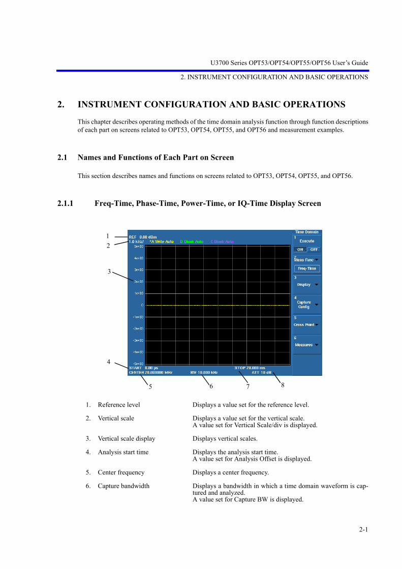
U3700 Series OPT53/OPT54/OPT55/OPT56 User’s Guide
2. INSTRUMENT CONFIGURATION AND BASIC OPERATIONS
2-1
2. INSTRUMENT CONFIGURATION AND BASIC OPERATIONS
This chapter describes operating methods of the time domain analysis function through function descriptionsof each part on screens related to OPT53, OPT54, OPT55, and OPT56 and measurement examples.
2.1 Names and Functions of Each Part on Screen
This section describes names and functions on screens related to OPT53, OPT54, OPT55, and OPT56.
2.1.1 Freq-Time, Phase-Time, Power-Time, or IQ-Time Display Screen
1. Reference level Displays a value set for the reference level.
2. Vertical scale Displays a value set for the vertical scale.A value set for Vertical Scale/div is displayed.
3. Vertical scale display Displays vertical scales.
4. Analysis start time Displays the analysis start time.A value set for Analysis Offset is displayed.
5. Center frequency Displays a center frequency.
6. Capture bandwidth Displays a bandwidth in which a time domain waveform is cap-tured and analyzed.A value set for Capture BW is displayed.
12
3
4
5 6 7 8
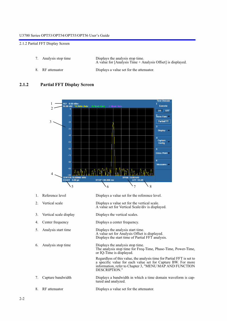
U3700 Series OPT53/OPT54/OPT55/OPT56 User’s Guide
2.1.2 Partial FFT Display Screen
2-2
7. Analysis stop time Displays the analysis stop time.A value for [Analysis Time + Analysis Offset] is displayed.
8. RF attenuator Displays a value set for the attenuator.
2.1.2 Partial FFT Display Screen
1. Reference level Displays a value set for the reference level.
2. Vertical scale Displays a value set for the vertical scale.A value set for Vertical Scale/div is displayed.
3. Vertical scale display Displays the vertical scales.
4. Center frequency Displays a center frequency.
5. Analysis start time Displays the analysis start time.A value set for Analysis Offset is displayed.Displays the start time of Partial FFT analysis.
6. Analysis stop time Displays the analysis stop time.The analysis stop time for Freq-Time, Phase-Time, Power-Time,or IQ-Time is displayed.Regardless of this value, the analysis time for Partial FFT is set toa specific value for each value set for Capture BW. For moreinformation, refer to Chapter 3, "MENU MAP AND FUNCTIONDESCRIPTION."
7. Capture bandwidth Displays a bandwidth in which a time domain waveform is cap-tured and analyzed.
8. RF attenuator Displays a value set for the attenuator.
12
3
4
5 6 7 8

U3700 Series OPT53/OPT54/OPT55/OPT56 User’s Guide
2.1.3 OPT54 2-channnel Display Window
2-3
2.1.3 OPT54 2-channnel Display Window
Figure 2-1 Screen Display of DUAL CH ON 2 Screens
1. Operation mode When DUAL CH ON: Displays 2chSPA.When DUAL CH OFF: Nothing is displayed.
2. Active channel display Indicates the active channel, where settings can be changed, byusing the red rectangular box.
3. Active channel display Channel 1: CH1Channel 2: CH2Couple CH ON: CPL
4. CH1 display window
5. CH2 display window
123
4
5

U3700 Series OPT53/OPT54/OPT55/OPT56 User’s Guide
2.2 Operating Method
2-4
2.2 Operating Method
This section describes the functions and operating methods of the time domain analysis option through mea-surement examples.
By using the time domain analysis function, changes of RF signal characteristics with time can be measuredas each waveform of frequency, phase, power, I/Q waveforms, or spectrum.
For more information on this instrument configuration and basic operations, refer to the U3700 series user'smanual.
This section describes the FSK (Frequency Shift Keying) modulated signal measurement as an example.
• Signal Source outputFrequency: 2.45 GHzPower: 0 dBmModulation Type: FSKFrequency Deviation: 40 kHzp-pBaseband Signal: 2 kHz PRBS
Signal Source
RF Coaxial Cable (Loss: 2 dB)

U3700 Series OPT53/OPT54/OPT55/OPT56 User’s Guide
2.2.1 Capturing I/Q Waveforms of RF Signal
2-5
2.2.1 Capturing I/Q Waveforms of RF Signal
This section describes procedures for capturing an RF signal into the internal memory of this instrumentas I/Q waveforms.
2.2.1.1 Setting Center Frequency, Reference Level, and Sweep Mode
1. Press FREQUENCY, 2, ., 4, 5, and GHz.The center frequency is set to 2.45 GHz.
2. Press AMPLITUDE, 0, and GHz.The reference level is set to 0 dBm.
3. Press EXT CFG and Sweep Mode SGL/CNT to select SGL.The sweep mode is set to Single.
2.2.1.2 Setting Waveform Capture Time and Capture Bandwidth
1. Press MEAS 2, More 1/2, and Time Domain.The time domain analysis menu is displayed.
2. Press Capture Config.The waveform capture setting menu is displayed.
3. Press Capture BW, 1, 0, 0, and kHz.The waveform capture bandwidth is set to 100 kHz.
4. Press Capture Time, 2, 0, 0, and kHz.The waveform capture time is set to 200 msec.
5. Press RETURN.The display returns to the time domain analysis menu.
2.2.1.3 Starting and Stopping RF Signal Capture
1. Press Execute ON/OFF and select ON.The time domain analysis function is enabled.
2. Press START/STOP.Capturing an RF signal starts.That automatically stops 200 msec after the capture start according to settings ofCapture Time (200 ms) and Sweep Mode (Single).

U3700 Series OPT53/OPT54/OPT55/OPT56 User’s Guide
2.2.2 Analyzing RF Signal
2-6
2.2.2 Analyzing RF Signal
This section describes procedures for performing various analyses from waveform data captured in theinternal memory of this instrument.
Captured I/Q waveforms can be analyzed from various viewpoints of frequency, phase, power, I/Q wave-forms, and FFT spectrum by using each function of the Meas Func menu.
2.2.2.1 Freq-Time Analysis
Function setting
1. Press Meas Func.The analysis function selection menu is displayed.
2. Press Freq-Time.The analysis function for "frequency versus time" is selected.
3. Press RETURN.The display returns to the time domain analysis menu.The currently selected analysis function is displayed on the Meas Func key.
Display setting
4. Press Display.Menus for analysis time range setting (horizontal axis) and data display setting(vertical axis) are displayed.
5. Press Analysis Offset, 0, and MHz.The analysis time offset is set to 0 sec.
6. Press Analysis Window, 2, 0, and kHz.The analysis time length is set to 20 msec.
7. Press Vertical Position, 0, and Hz.The vertical offset of the data display is set to 0 Hz.
8. Press Vertical Scale/div, 1, 0, and kHz.The vertical scale of the data display is set to 10 kHz/div.
9. Press MKR.An instant frequency at the marker display position can be measured.

U3700 Series OPT53/OPT54/OPT55/OPT56 User’s Guide
2.2.2 Analyzing RF Signal
2-7
10. Press MEAS 2 and RETURN.The display returns to the time domain analysis menu.
2.2.2.2 Phase-Time Analysis
Function setting
1. Press Meas Func.The analysis function selection menu is displayed.
2. Press Phase-Time.The analysis function for "phase versus time" is selected.
3. Press RETURN.The display returns to the time domain analysis menu.The currently selected analysis function is displayed on the Meas Func key.
Display setting
4. Press Display.Menus for analysis time range setting (horizontal axis) and data display setting(vertical axis) are displayed.
5. Press Analysis Offset, 0, and MHz.The analysis time offset is set to 0 sec.
6. Press Analysis Window, 1, and kHz.The analysis time length is set to 1 msec.
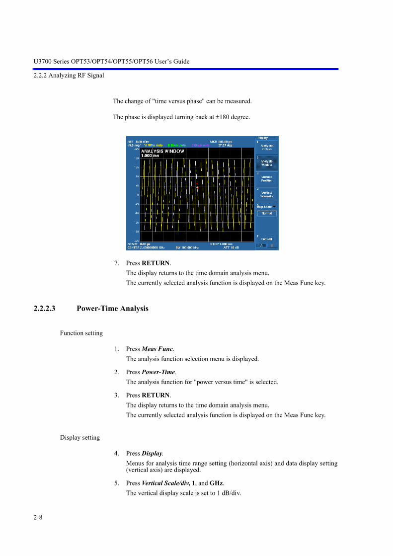
U3700 Series OPT53/OPT54/OPT55/OPT56 User’s Guide
2.2.2 Analyzing RF Signal
2-8
The change of "time versus phase" can be measured.
The phase is displayed turning back at ±180 degree.
7. Press RETURN.The display returns to the time domain analysis menu.The currently selected analysis function is displayed on the Meas Func key.
2.2.2.3 Power-Time Analysis
Function setting
1. Press Meas Func.The analysis function selection menu is displayed.
2. Press Power-Time.The analysis function for "power versus time" is selected.
3. Press RETURN.The display returns to the time domain analysis menu.The currently selected analysis function is displayed on the Meas Func key.
Display setting
4. Press Display.Menus for analysis time range setting (horizontal axis) and data display setting(vertical axis) are displayed.
5. Press Vertical Scale/div, 1, and GHz.The vertical display scale is set to 1 dB/div.

U3700 Series OPT53/OPT54/OPT55/OPT56 User’s Guide
2.2.2 Analyzing RF Signal
2-9
The change of "time versus power" can be measured.
6. Press RETURN.The display returns to the time domain analysis menu.The currently selected analysis function is displayed on the Meas Func key.
2.2.2.4 IQ-Time Analysis
Function setting
1. Press TRACE, Trace(B), Refresh, and Refresh(Write).Trace B is set to Write.
When the IQ-Time analysis function is selected, an I and Q waveform is allocatedto Trace A and Trace B, respectively.
2. Press Trace(C) and Trace(A) in order.The selected state of Active Trace is changed as Trace B → Trace C → Trace Ain order. In this case, Trace A is Active Trace and the Trace A waveform is dis-played at the front.
3. Press MEAS 2.The display returns to the time domain analysis menu.The currently selected analysis function is displayed on the Meas Func key.
4. Press Meas Func.The analysis function selection menu is displayed.
5. Press IQ-Time.The analysis function for "I/Q voltage versus time" is selected.
6. Press RETURN.

U3700 Series OPT53/OPT54/OPT55/OPT56 User’s Guide
2.2.2 Analyzing RF Signal
2-10
The display returns to the time domain analysis menu.The currently selected analysis function is displayed on the Meas Func key.
Display setting
7. Press Display.Menus for analysis time range setting (horizontal axis) and data display setting(vertical axis) are displayed.
8. Press Vertical Scale/div, 1, 0, 0, and kHz.The vertical display scale is set to 100 mV/div.
For I and Q, the change of "time versus voltage" can be measured.
9. Press RETURN.The display returns to the time domain analysis menu.The currently selected analysis function is displayed on the Meas Func key.
2.2.2.5 Partial FFT Analysis
Function setting
1. Press Meas Func.The analysis function selection menu is displayed.
2. Press Partial FFT.The Partial FFT spectrum analysis function is selected.
Frequency components included in the specified part of the time waveform can bemeasured.

U3700 Series OPT53/OPT54/OPT55/OPT56 User’s Guide
2.2.2 Analyzing RF Signal
2-11
The analysis start point is set by Analysis Offset. The FFT analysis time length is setto a specific value for each setting value of Capture BW but not set by Analysis Time.
For more information, refer to Chapter 3, "MENU MAP AND FUNCTIONDESCRIPTION."
The frequency Span on the FFT spectrum display is the same as the frequency band-width set by Capture BW and the frequency resolution is one hundredth of Span.
In this measurement example, Span is 100 kHz, frequency resolution is 1 kHz, andFFT analysis time length is 10 ms because Capture BW=100 kHz. (For the horizontalaxis of 1001 points)
3. Press RETURN.The display returns to the time domain analysis menu.The currently selected analysis function is displayed on the Meas Func key.
Display setting
4. Press Display.Menus for analysis time range setting (horizontal axis) and data display setting(vertical axis) are displayed.
5. Press Vertical Scale/div, 1, 0, and GHz.The vertical display scale is set to 10 dB/div.
The Partial FFT spectrums are displayed and frequency components included in thespecified part of the time waveform can be measured.
6. Press RETURN.The display returns to the time domain analysis menu.The currently selected analysis function is displayed on the Meas Func key.

U3700 Series OPT53/OPT54/OPT55/OPT56 User’s Guide
2.2.2 Analyzing RF Signal
2-12
2.2.2.6 Freq-Time Analysis Using Position View Function
Function setting
1. Press Meas Func.The analysis function selection menu is displayed.
2. Press Freq-Time.The analysis function for "frequency versus time" is selected.
3. Press RETURN.The display returns to the time domain analysis menu.The currently selected analysis function is displayed on the Meas Func key.
Display setting
4. Press Display.Menus for analysis time range setting (horizontal axis) and data display setting(vertical axis) are displayed.
5. Press Analysis Window, 2, 0, and kHz.The analysis time length is set to 20 msec.
6. Press Analysis Offset, 1, 0, and kHz.The analysis time offset is set to 10 msec.
7. Press Vertical Position, 0, and Hz.The vertical offset of the data display is set to 0 Hz.
8. Press Vertical Scale/div, 1, 0, and kHz.The vertical scale of the data display is set to 10 kHz/div.
9. Press Display Mode and Position View to select the Position View function.The lower screen displays the analysis result for the entire waveform capturetime. The window displayed in the lower screen indicates the position of the setanalysis time.The upper screen displays the analysis result for the time set by analysis timelength and offset.
10. Press EXT CFG and Sweep Mode SGL/CNT to select SGL.The sweep mode is set to Single.
11. Press START/STOP.Capturing an RF signal starts.

U3700 Series OPT53/OPT54/OPT55/OPT56 User’s Guide
2.2.2 Analyzing RF Signal
2-13
12. Press MEAS2 and RETURN.Press Analysis Offset and Analysis Window in the Display menu and change theset value.The analysis position and analysis result can be checked.
13. Press Disp Mode and Normal.The Position View mode is canceled.
14. Press RETURN twice.The display returns to the time analysis menu.
15. Press EXT CFG and Sweep Mode SGL/CNT to select CNT.The sweep mode is set to CNT.
CAUTION: To make the analysis window content in the lower screen match the analysis result inthe upper screen, set the sweep mode to Single and capture data by pressing START/STOP.

U3700 Series OPT53/OPT54/OPT55/OPT56 User’s Guide
2.2.2 Analyzing RF Signal
2-14
2.2.2.7 Two-Type Simultaneous Analysises Using Dual Meas Function (Freq-Timeand Phase-Time)
Function setting
1. Press MEAS2 and Meas Func.The analysis function selection menu is displayed.
2. Press Freq-Time.The analysis function for "frequency versus time" is selected.
3. Press RETURN.The display returns to the time domain analysis menu.The currently selected analysis function is displayed on the Meas Func key.
Display setting
4. Press Display.Menus for analysis time range setting (horizontal axis) and data display setting(vertical axis) are displayed.
5. Press Analysis Window, 1, and kHz.The analysis time length is set to 1 msec.
6. Press Analysis Offset, 0, and kHz.The analysis time offset is set to 0 sec.
7. Press Vertical Position, 0, and Hz.The vertical offset of the data display is set to 0 Hz.
8. Press Vertical Scale/div, 1, 0, and kHz.The vertical scale of the data display is set to 10 kHz/div.
9. Press Disp Mode and Dual Measure to select the Dual Measure function.At this time, Analysis Offset and Analysis Window values are copied to the lowerscreen.
Display setting (lower screen)
10. Press Context A/B to select B.
11. Press RETURN twice.The display returns to the time domain analysis menu.
12. Press Meas Func.The analysis function selection menu is displayed.
13. Press Phase-Time.

U3700 Series OPT53/OPT54/OPT55/OPT56 User’s Guide
2.2.2 Analyzing RF Signal
2-15
The analysis function for "phase versus time" is selected.
14. Press EXT CFG and Sweep Mode SGL/CNT to select SGL.The sweep mode is set to Single.
15. Press START/STOP.Capturing an RF signal starts.
16. Press MEAS2 and RETURN.Press Analysis Offset and Analysis Window in the Display menu and change theset value.Only the analysis time in the lower screen can be changed.Based on the captured data, analysis can be performed with independent settingsfor the upper and lower screens.
17. Press Disp Mode and Normal.The Dual Measure mode is canceled.

U3700 Series OPT53/OPT54/OPT55/OPT56 User’s Guide
2.3 OPT55 Pulse Modulation Signal Measurement Example
2-16
2.3 OPT55 Pulse Modulation Signal Measurement Example
In this section, a PM (Pulse Modulation) signal is measured.
• Signal Source outputFrequency: 1.5 GHzPower: -20 dBmModulation Type: Pulse ModulationPeriod: 10 μsWidth: 1 μs
OperationSetting the Center Frequency:
1. Press SHIFT and SYSTEM(PRESET).Initial setting conditions are loaded.
2. Press FREQUENCY, 1, 5, 0, 0, and MHz.The center frequency is set to 1500 MHz.
3. Press SPAN, 1, 0, and MHz.The frequency span is set to 10 MHz.
Signal Source

U3700 Series OPT53/OPT54/OPT55/OPT56 User’s Guide
2.3 OPT55 Pulse Modulation Signal Measurement Example
2-17
Power-Time analysis
4. Press MEAS2, More1/2, and Time Domain.The time domain analysis menu is displayed.
5. Press Meas Func and Power-Time.The analysis function for "power versus time" is selected.
6. Press RETURN.The display returns to the time domain analysis menu.The currently selected analysis function is displayed on the Meas Func key.
7. Press Capture Config.The waveform capture setting menu is displayed.
8. Press Capture BW, 3, 0, and MHz.The waveform capture bandwidth is set to 30 MHz.
9. Press Capture Time, 5, 0, and Hz.The waveform capture time is set to 50 μs.
10. Press RETURN and ExecuteON/OFF(ON).Execute the Power-Time analysis function.
Pulse width measurement
11. Press EXT CFG, Trigger, Source, and IF.The IF trigger is selected.
12. Press MEAS2, Display, Analysis Window, 2, 0, and Hz.The analysis time length is set to 20 μs.

U3700 Series OPT53/OPT54/OPT55/OPT56 User’s Guide
2.3 OPT55 Pulse Modulation Signal Measurement Example
2-18
13. Press RETURN, Measures, Threshold ON/OFF(ON), -, 3, 0, and GHz.The Threshold line used as reference of Measures is set to -30 dBm.
14. Press Width and Positive Width.The pulse width measurement result across the -30 dBm level is displayed in thelower part of the screen.
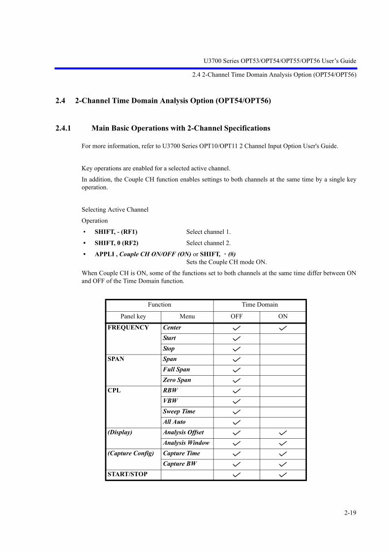
U3700 Series OPT53/OPT54/OPT55/OPT56 User’s Guide
2.4 2-Channel Time Domain Analysis Option (OPT54/OPT56)
2-19
2.4 2-Channel Time Domain Analysis Option (OPT54/OPT56)
2.4.1 Main Basic Operations with 2-Channel Specifications
For more information, refer to U3700 Series OPT10/OPT11 2 Channel Input Option User's Guide.
Key operations are enabled for a selected active channel.
In addition, the Couple CH function enables settings to both channels at the same time by a single keyoperation.
Selecting Active Channel
Operation
• SHIFT, - (RF1) Select channel 1.
• SHIFT, 0 (RF2) Select channel 2.
• APPLI , Couple CH ON/OFF (ON) or SHIFT, (#)Sets the Couple CH mode ON.
When Couple CH is ON, some of the functions set to both channels at the same time differ between ONand OFF of the Time Domain function.
Function Time Domain
Panel key Menu OFF ON
FREQUENCY CenterStartStop
SPAN SpanFull SpanZero Span
CPL RBWVBWSweep TimeAll Auto
(Display) Analysis OffsetAnalysis Window
(Capture Config) Capture TimeCapture BW
START/STOP

U3700 Series OPT53/OPT54/OPT55/OPT56 User’s Guide
2.4.2 Example of Four-Value FSK Signal Analysis
2-20
2.4.2 Example of Four-Value FSK Signal Analysis
This section measures a frequency change for four-value FSK signal time on the time axis and frequencyaxis at the same time.
• Signal Source outputFrequency: 150 MHzPower: 0 dBmModulation Type: 4FSKFrequency Deviation: 9.6 kHzp-pBaseband Signal: 3.2 kHz PRBS
Operation
Setting the Center Frequency
1. Press SHIFT and SYSTEM(PRESET).Initial setting conditions are loaded.Channel 1 is set to the active channel.
Signal Source
Power Divider
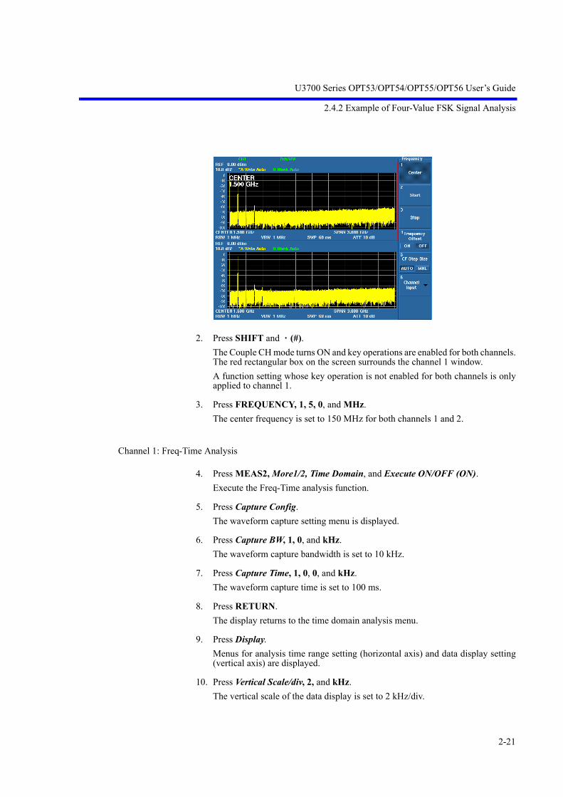
U3700 Series OPT53/OPT54/OPT55/OPT56 User’s Guide
2.4.2 Example of Four-Value FSK Signal Analysis
2-21
2. Press SHIFT and (#).The Couple CH mode turns ON and key operations are enabled for both channels.The red rectangular box on the screen surrounds the channel 1 window.A function setting whose key operation is not enabled for both channels is onlyapplied to channel 1.
3. Press FREQUENCY, 1, 5, 0, and MHz.The center frequency is set to 150 MHz for both channels 1 and 2.
Channel 1: Freq-Time Analysis
4. Press MEAS2, More1/2, Time Domain, and Execute ON/OFF (ON).Execute the Freq-Time analysis function.
5. Press Capture Config.The waveform capture setting menu is displayed.
6. Press Capture BW, 1, 0, and kHz.The waveform capture bandwidth is set to 10 kHz.
7. Press Capture Time, 1, 0, 0, and kHz.The waveform capture time is set to 100 ms.
8. Press RETURN.The display returns to the time domain analysis menu.
9. Press Display.Menus for analysis time range setting (horizontal axis) and data display setting(vertical axis) are displayed.
10. Press Vertical Scale/div, 2, and kHz.The vertical scale of the data display is set to 2 kHz/div.

U3700 Series OPT53/OPT54/OPT55/OPT56 User’s Guide
2.4.2 Example of Four-Value FSK Signal Analysis
2-22
Channel2: Spectrum Display by Partial FFT Analysis
11. Press SHIFT and 0 (RF2).Channel 2 is set to the active channel.
12. Press RETURN.The display returns to the time domain analysis menu.
13. Press Meas Func and Partial FFT.The Partial FFT spectrum analysis function is selected.
14. Press RETURN and Execute ON/OFF (ON).Execute the Partial FFT spectrum analysis function.At this time, the waveform capture bandwidth (10 kHz) and the capture time (100ms) are set in steps 6 and 7, which are performed while Couple CH is ON.
15. Press TRACE, Calc, and Max Hold.Max Hold starts.

U3700 Series OPT53/OPT54/OPT55/OPT56 User’s Guide
2.4.2 Example of Four-Value FSK Signal Analysis
2-23
Changing Capture BW
16. Press MEAS2 and Capture Config.The waveform capture setting menu is displayed.
17. Press Capture BW, 1, 0, 0, and kHz.The waveform capture bandwidth is set to 100 kHz.At this time, channel 2 is an active channel.Because the Couple CH function is cancelled, the waveform capture bandwidthis set only for channel 2.


U3700 Series OPT53/OPT54/OPT55/OPT56 User’s Guide
3. MENU MAP AND FUNCTION DESCRIPTION
3-1
3. MENU MAP AND FUNCTION DESCRIPTION
This chapter describes the functions of the panel keys and soft keys in the items shown below.
Menu Map: This section shows the menu configurations of the panel keys.
Functional Descriptions: This section describes the functions of the panel keys and soft keys.
3.1 Functional Descriptions
This section describes the functions of the panel keys and soft keys.
MEMO:
• indicates a panel key.• All other names are soft menus.
3.1.1 Time Domain
Displays the Time Domain menu.

U3700 Series OPT53/OPT54/OPT55/OPT56 User’s Guide
3.1.1 Time Domain
3-2
MEAS 2
Execute ON/OFFMeas FuncDisplayCapture ConfigCross PointMeasures
Freq-TimePhase-TimePower-TimeIQ-TimePartial FFT
Analysis OffsetAnalysis WindowVertical PositionVertical Scale/divDisp ModeContext A/B
More 1/2
Time Domain
Capture TimeCapture BW
Search RightSearch LeftSlope UP/DN/ALLThreshold ON/OFF
OFFDuty CycleFrequencyWidthThreshold ON/OFF
NormalPosition ViewDual MeasureContext A/B
Positive Duty CycleNegative Duty CyclePositive WidthNegative Width

U3700 Series OPT53/OPT54/OPT55/OPT56 User’s Guide
3.1.1 Time Domain
3-3
Time Domain Displays the time domain analysis menu.
Execute ON/OFF Selects ON or OFF of the time domain analysis function.
Meas Func Selects the time domain measurement function.
The currently selected analysis function is displayed on the MeasFunc key.
Freq-Time Displays a change of "measured signal frequency versus time"based on the center frequency setting value of the analyzer.
Phase-Time Displays a change of "measured signal phase versus time" basedon the center frequency setting value of the analyzer.
Power-Time Displays a change of "measured signal power versus time".
IQ-Time Displays a change of "measured signal I/Q voltages versus time".
An I and Q waveform is captured and displayed on Trace A andTrace B, respectively.
Partial FFT Displays frequency spectrums of the measured signal.
The frequency span is the same as Capture BW. The resolutionbandwidth is one hundredth of span.
The Partial FFT analysis start point is specified by Analysis Off-set. The analysis data length is the fixed length but not set byAnalysis Window. (See Table 3-1 and Table 3-2.)
Display Sets the analysis time (horizontal axis) and analysis result (verti-cal axis) display ranges.
Analysis Offset Sets the analysis start point (Offset time from the top of the cap-tured waveform) of the measured signal waveform captured in theanalyzer.
Analysis Window Sets the analysis time length (time that starts at the Analysis Off-set setting value) of the measured signal waveform captured in theanalyzer.
For the Partial FFT analysis, the analysis time length is a valuethat depends on Capture BW and the number of horizontal points(See Table 3-1 and Table 3-2.).
Vertical Position Sets the vertical display position of the analysis result.
For each analysis function selected by Meas Func, each indepen-dent vertical display position is set.
Vertical Scale/div Sets the vertical display scale of the analysis result.
For each analysis function selected by Meas Func, each indepen-dent vertical display scale is set.
Disp Mode Selects a screen mode.
Normal Sets the measurement screen to the single-screen display mode.
Position View Sets the Position View function. The display is divided into upperand lower screens.
The upper and lower screens display the analysis results of thesame captured waveform data.
The upper screen displays the normal analysis result.

U3700 Series OPT53/OPT54/OPT55/OPT56 User’s Guide
3.1.1 Time Domain
3-4
The lower screen displays the result for the entire captured timerange of the obtained data.
The blue window in the lower screen displays the analysis starttime and analysis time length for the upper screen.
Upper screen: Analysis Window=user set value, Analysis Offset=user set value
Lower screen: Analysis Window=Capture Time (fixed), Analysis Offset=0sec (fixed)
Dual Measure Sets the Dual Measure function. The display is divided into upperand lower screens.
The upper and lower screens display the analysis results of thesame captured waveform data.
Different analysis functions can be set individually to the upperand lower screens. Also, the vertical axis display position, verticalaxis scale, analysis start time, and analysis time length can be setfor each screen.
Context A/B Switches the active screen between A (upper screen) and B (lowerscreen).
A: The upper screen settings can be changed.
B: The lower screen setting can be changed.
Context A/B Selects the screen, for which the setting is to be made, when DualMeas ON is set.
Capture Config Sets the capture time length of the waveform captured in the ana-lyzer and the frequency bandwidth.
Capture Time Sets the capture time length of the waveform captured in the ana-lyzer.
The maximum capture time depends on the Capture BW setting.(See Table 3-3 and Table 3-4.)
Capture BW Sets the frequency bandwidth of the waveform captured in theanalyzer.
For the Capture BW setting, Capture Time is automatically lim-ited to a value within the maximum capture time. (See Table 3-3and Table 3-4.)

U3700 Series OPT53/OPT54/OPT55/OPT56 User’s Guide
3.1.1 Time Domain
3-5
Table 3-1 OPT53/OPT54 Capture BW Setting Value and Partial FFT Frequency Resolution
Capture BWBandwidth setting value
Partial FFTFrequency resolution
Partial FFT analysis data length
Horizontal axis of 1001 points Horizontal axis of 501 points
3 MHz 30 kHz 0.33 msec 0.165 msec
1 MHz 10 kHz 1 msec 0.5 msec
300 kHz 3 kHz 3.3 msec 1.65 msec
100 kHz 1 kHz 10 msec 5 msec
30 kHz 300 Hz 33 msec 16.5 msec
10 kHz 100 Hz 100 msec 50 msec
3 kHz 30 Hz 330 msec 165 msec
1 kHz 10 Hz 1 sec 500 msec
300 Hz 3 Hz 3.3 sec 1.65 sec
100 Hz 1 Hz 10 sec 5 sec
Table 3-2 OPT55/OPT56 Capture BW Setting Value and Partial FFT Frequency Resolution
Capture BWBandwidth setting value
Partial FFTFrequency resolution
Partial FFT analysis data length
Horizontal axis of 1001 points Horizontal axis of 501 points
40 MHz 400 kHz 25 μsec 12.5 μsec
30 MHz 300 kHz 33 μsec 16.5 μsec
10 MHz 100 kHz 100 μsec 50 μsec
3 MHz 30 kHz 330 μsec 0.165 msec
1 MHz 10 kHz 1 msec 0.5 msec
300 kHz 3 kHz 3.3 msec 1.65 msec
100 kHz 1 kHz 10 msec 5 msec
30 kHz 300 Hz 33 msec 16.5 msec
10 kHz 100 Hz 100 msec 50 msec
3 kHz 30 Hz 330 msec 165 msec
1 kHz 10 Hz 1 sec 500 msec
300 Hz 3 Hz 3.3 sec 1.65 sec
100 Hz 1 Hz 10 sec 5 sec

U3700 Series OPT53/OPT54/OPT55/OPT56 User’s Guide
3.1.1 Time Domain
3-6
Table 3-3 OPT53/OPT54 Capture BW Setting Value and Capture Time Maximum Value
Capture BW Bandwidth setting value Capture Time Maximum capture time
3 MHz 50 msec
1 MHz 150 msec
300 kHz 500 msec
100 kHz 1.5 sec
30 kHz 5 sec
10 kHz 15 sec
3 kHz 50 sec
1 kHz 150 sec
300 Hz 500 sec
100 Hz 1000 sec
Table 3-4 OPT55/OPT56 Capture BW Setting Value and Capture Time Maximum Value
Capture BW Bandwidth setting value Capture Time Maximum capture time
40 MHz 120 ms
30 MHz 120 ms
10 MHz 240 ms
3 MHz 600 msec
1 MHz 2.0 sec
300 kHz 6.0 sec
100 kHz 20 sec
30 kHz 60 sec
10 kHz 200 sec
3 kHz 600 sec
1 kHz 1000 sec
300 Hz 1000 sec
100 Hz 1000 sec

U3700 Series OPT53/OPT54/OPT55/OPT56 User’s Guide
3.1.1 Time Domain
3-7
Cross Point Detects waveform edges (rising and falling).
Search Right Searches in the right direction from the active marker.
Search Left Searches in the left direction from the active marker.
Slope UP/DN/ALL
UP: Searches for waveform rising points and moves the active marker there.
Waveform rising points refer to where the waveform crosses the threshold line from down to up.
DN: Searches for waveform falling points and moves the active marker there.
Waveform falling points refer to where the waveform crosses the threshold line from up to down.
ALL: Searches for waveform rising and falling points alternatively and moves the active marker there.
Threshold ON/OFF Select ON/OFF for the threshold line.
This is the reference line for Cross Point search.
Measures Performs measurement for the time domain screen.
OFF Quits measuring.
Duty Cycle Displays Duty Cycle measurement menus.
Positive Duty CycleMeasures the ratio of the positive pulse width contained in thefirst cycle.
Positive Duty Cycle(%) = Positive pulse width / Cycle * 100%
Negative Duty CycleMeasures the ratio of the negative pulse width contained in thefirst cycle.
Negative Duty Cycle(%) = Negative pulse width / Cycle * 100%
Frequency Measures the frequency in the first cycle.
Frequency(Hz) = 1 / Cycle
Width Displays Width measurement menus.
Positive Width Measures the positive pulse width.
Positive Width(sec) = (The point where a waveform first crossesthe threshold line from up to down) - (The point where a wave-form first crosses the threshold line from down to up)
Negative Width Measures the negative pulse width.
Negative Width(sec) = (The point where a waveform first crossesthe threshold line from down to up) - (The point where a wave-form first crosses the threshold line from up to down)

U3700 Series OPT53/OPT54/OPT55/OPT56 User’s Guide
3.1.1 Time Domain
3-8
Threshold ON/OFF Select ON/OFF for the threshold line.
This is the reference line for Measures.

U3700 Series OPT53/OPT54/OPT55/OPT56 User’s Guide
3.1.2 MKR→
3-9
3.1.2 MKR→
When the time domain analysis function is on, the MKR→ function changes according to the selectedmeasurement function.
Meas Func: Freq-Time, Phase-Time, Power-Time, or IQ-Time
Mkr to Analysis Ofs Sets the time at the active marker as the analysis start point.
Delta to Analysis Win Sets the time difference between delta and normal markers as theanalysis time length.
Mkr to Vertical Pos Sets the level at the active marker as the vertical axis display posi-tion.
Delta to V Scale/div Sets the level difference between delta and normal markers as thevertical axis display scale.
Mkr to Mkr Step Sets the time at the active marker as the step size of the marker.
Meas Func: Partial FFT
Mkr to CF Sets the frequency at the active marker as the center frequency.
Peak to CF Displays the marker at the highest peak in the search target rangeand sets the frequency at the marker as the center frequency.
Mkr to Vertical Pos Sets the level at the active marker as the vertical axis display posi-tion.
Delta to V Scale/div Sets the level difference between delta and normal markers as thevertical axis display scale.
Mkr to CF Step Sets the frequency at the active marker as the step size of the cen-ter frequency.
Mkr to Mkr Step Sets the frequency at the active marker as the step size of themarker.
Peak to Ref Displays the marker at the highest peak in the search target rangeand sets the level at the marker as the reference level.
MKR Mkr to Analysis OfsDelta to Analysis WinMkr to Vertical PosDelta to V Scale/divMkr to Mkr Step
MKR→ Mkr to CFPeak to CFMkr to Vertical PosDelta to V Scale/divMkr to CF StepMkr to Mkr StepPeak to Ref


U3700 Series OPT53/OPT54/OPT55/OPT56 User’s Guide
4. OVERVIEW OF REMOTE CONTROL
4-1
4. OVERVIEW OF REMOTE CONTROL
This chapter describes the AT command reference for this instrument.
4.1 GPIB Remote Programming
This section shows the AT commands in each function:
• Command codeAn asterisk "*" indicates a function that numeric or character strings data follows after the code.Numeric data and "ON" can be omitted from [ ].
• Output format
• A comma "," indicates that two or more data are output.
• ON or OFF indicates that 1 or 0 is output.
• Frequency is output in Hz and time is output in sec.
• Level data is output in the currently set display unit.
4.2 AT Command Code List
FunctionCommand (EXE, SET) Query (GET)
Code Argument Format Code Output FormatTime Domain Analysis TDANA ON/OFF TDANAON? 0:OFF
1:ONAnalysis Offset TDAOFS Time TDAOFS? TimeAnalysis Window TDATIM Time TDATIM? TimeVertical Scale IQ VSCLIQ Voltage VSCLIQ? VoltageVertical Scale Power VSCLPWR Power VSCLPWR? PowerVertical Scale Freq VSCLFRE Frequency VSCLFRE? FrequencyVertical Scale Phase VSCLPHA Phase VSCLPHA? PhaseVertical Scale FFT VSCLFFT Level VSCLFFT? LevelVertical Position IQ VPOSIQ Position VPOSIQ? PositionVertical Position Power VPOSPWR Position VPOSPWR? PositionVertical Position Freq VPOSFRE Position VPOSFRE? PositionVertical Position Phase VPOSPHA Position VPOSPHA? PositionVertical Position FFT VPOSFFT Position VPOSFFT? Position

U3700 Series OPT53/OPT54/OPT55/OPT56 User’s Guide
4.2 AT Command Code List
4-2
Measurement Function TMEAS FRE/PHA/PWR/IQ/FFT TMEAS? 0:FRE1:PHA2:PWR3:IQ4:FFT
Capture Time CAPTIM Time CAPTIM? TimeCapture BW CAPBW Frequency CAPBW? FrequencyDisplay Mode TDDISP * NORM|POSV|DUAL TDDISP? 0=Normal
1=Position View2=Dual Measure
Cross point Search Right
CRSPR --- --- ---
Cross point Search Left CRSPL --- --- ---Slope CRSSLP * UP|DN|ALL CRSSLP? 0=Up
1=Down2=All
Threshold THRIQ *THRPWR *THRFRE *THRPHA *THRFFT *
THRESH ON|OFF
VoltdBmFrequencyPhasedBm
THRIQ?THRPWR?THRFRE?THRPHA?THRFFT?
THRESHON?
VoltdBmFrequencyPhasedBm
0=OFF1=ON
Measures
Measures Result
DMEAS *
---
OFF/DTYP/DTYNFREQ/WIDP/WIDN
---
DMEAS?
DMEASRES?
0:OFF1:Pos Duty2:Neg Duty3:Freq4:Pos Wid5:Neg Wid
RealMkr to Analysis Offs MKAO --- --- ---Delta Mkr to Analysis Win
MTAW --- --- ---
Mkr to Vertical Pos MKVP --- --- ---Delta Mkr to scale/div MTDIV --- --- ---IQ Output Binary --- --- IQB? 8 bytes x IQP (*1)IQ Output Scale --- --- IQS? RealIQ Output Points --- --- IQP? PointsIQ Sample Rate --- --- IQR? FrequencyALL IQ Sample Points --- --- IQPAL? PointsClear IQP value IQPRST --- --- ---(*1) IQP : Number of IQ Pair Sample Points
FunctionCommand (EXE, SET) Query (GET)
Code Argument Format Code Output Format

U3700 Series OPT53/OPT54/OPT55/OPT56 User’s Guide
4.3 I/Q Data Output
4-3
4.3 I/Q Data Output
Data output by IQB? is in Binary (32bit) format, and I and Q are alternately output.
Data output by IQB? shows a relative value between I and Q, and it can be used for phase angle calculation.
Data output by IQS? shows scaling data for absolute value conversion of I and Q Pair.
Data output by IQPAL? shows the number of all I and Q Pairs which were captured.
Data output by IQP? shows the number of samples (N) of I and Q Pairs which is returned from the next-calledIQB?.
Data output by IQR? shows a sampling frequency of I and Q Pair.
IQPRST returns the IQP? value to the initial value.
Voltages (VIN, VQN) that correspond the Nth data (IN, QN) of I and Q output can be obtained by using thefollowing equations.
VIN=IN x IQS [V]
VQN=QN x IQS [V]
Example:
Obtain all IQ data items when the return value of IQPAL? is the 4.5M sample.
1. The first IQP? returns 2Mi, so obtain the 2M sample data by IQB?.
2. The second IQP? also returns 2Mi, so obtain the 2M sample data by IQB?.
3. The third IQP? returns 0.5Mi, so obtain the 0.5M sample data by IQB?.
4. The fourth IQP? returns 0, so the obtaining of data is complete.
Repeat IQB? to obtain all data items until IQP? returns 0.
Using the TS or IQPRST command returns to the initial state.
IQ-Pair data output (8xN bytes) of N obtained samples (0 to N-1)
Sample number 0 1 ... N-2 N-1
IQB? Data
I0 Q0 I1 Q1 ... ... IN-2 QN-2 IN-1 QN-1
Size Bytes
4 4 4 4 4 4 4 4 4 4


U3700 Series OPT53/OPT54/OPT55/OPT56 User’s Guide
5. SPECIFICATIONS
5-1
5. SPECIFICATIONS
This chapter describes the specifications of this instrument.
The performance of this instrument is guaranteed under the following conditions unless otherwise specified.
• The specified calibration period must be adhered to.
• After turning on the power and warming-up for 5 minutes or more under the specified environmental conditions.
• After automatic calibration has been performed.
5.1 Option 53, Option 54 Time Domain Analysis Option
5.2 Option 55, Option 56 Time Domain Analysis Option
Item Description
RF frequency range Conforms to the frequency range for each model of the U3700 series.
RF amplitude range Noise level to +30 dBm (*1)
Waveform capture format I/Q vector time waveform
Measurement bandwidth (BW) 100 Hz to 3 MHz (1 to 3 steps)
I/Q sampling rate 713 Hz (BW 100 Hz) to 21.4 MHz (BW 3 MHz)
I/Q waveform capture time 49 msec (BW 3 MHz) to 1000 sec (BW 100 Hz)
Number of I/Q waveform capture samples 1 M Samples (I/Q)
(*1) The noise level conforms to the dynamic range specifications for each model of the U3700 series.
Item Description
RF frequency range Conforms to the frequency range for each model of the U3700 series.
RF amplitude range Noise level to +30 dBm (*1)
Waveform capture format I/Q vector time waveform
Measurement bandwidth (BW) 100 Hz to 30 MHz (1 to 3 steps), 40 MHz
I/Q sampling rate 500 Hz (BW 100 Hz) to 65 MHz (BW 40 MHz)
I/Q waveform capture time 120 msec (BW 40 MHz) to 1000 sec (BW 100 Hz)
Number of I/Q waveform capture samples 8 M Samples (I/Q)
(*1) The noise level conforms to the dynamic range specifications for each model of the U3700 series.


U3700 Series OPT53/OPT54/OPT55/OPT56 User’s Guide
6. UNCAL MESSAGE, LIST OF ERROR MESSAGES, AND RESTRICTIONS
6-1
6. UNCAL MESSAGE, LIST OF ERROR MESSAGES, AND RESTRIC-TIONS
6.1 How to Delete UNCAL Message for Partial FFT Analysis
The Partial FFT analysis uses time length data that is related to the Capture BW setting value (equal to thedisplayed frequency Span). If the data length required for FFT analysis is insufficient, the UNCAL messageis displayed to show the displayed value may not be correct.
The UNCAL message is displayed if a relationship among each setting value of the FFT analysis data length,which is shown in Table 3-1 "Capture BW Setting Value and Partial FFT Frequency Resolution" of Chapter3, Capture Time, and Analysis Offset does not satisfy the following equation:
FFT analysis data length ≥ (Capture Time - Analysis Offset)
To delete the UNCAL message, perform either or both of the following (1) and (2).
(1) Increase the Capture Time setting value.
(2) Decrease the Analysis Offset setting value.
For more information on the Partial FFT analysis, refer to Chapter 3, "MENU MAP AND FUNCTIONDESCRIPTION."

U3700 Series OPT53/OPT54/OPT55/OPT56 User’s Guide
6.2 List Of Error Messages
6-2
6.2 List Of Error Messages
This chapter describes error messages regarding OPT53 and OPT54.
6.3 Restrictions
This section describes restrictions on the time domain analysis function.
6.3.1 Restrictions on Key Operation during Time Domain Analysis Function Use
When the time domain analysis function is set to ON, some key operations such as the frequency sweepSpan setting are temporarily unavailable. Unavailable keys are displayed in gray.
These are available again by setting the time domain analysis function to OFF.
6.3.2 Restrictions for Trace Data Capture
When the time domain analysis function is set to ON or OFF, or the analysis function is switched by MeasFunc, waveform data retained in the trace memory is invalid.
By operating TRACE, Refresh, and Refresh(Write), the trace memory can be updated to the latest wave-form.
Error code Type Displayed Message Description of Message
0/500 WARNING The Analysis Window is out of range.(Analysis Offset + Analysis Window <= Capture Time)
The Analysis Window value cannot be set.Ensure that the value of [Analysis Offset + Analysis Window] does not exceed the Capture Time value.
0/501 WARNING The Analysis Offset is out of range. (Analysis Offset + Analysis Window <= Capture Time)
The Analysis Offset value cannot be set.Ensure that the value of [Analysis Offset + Analysis Window] does not exceed the Capture Time value.
3/500 WARNING The Time Domain Analysis mode has been turned off.
The time domain analysis mode is can-celed.

U3700 Series OPT53/OPT54/OPT55/OPT56 User’s Guide
ALPHABETICAL INDEX
I-1
[Numerics]2-channel time domain analysis option (OPT54) .................................................. 2-19
[A]Analysis Offset ....................................... 3-2, 3-3Analysis Window .................................... 3-2, 3-3Analyzing RF Signal ............................... 2-6AT Command Code List ......................... 4-1
[B]BASIC OPERATIONS ........................... 2-1
[C]Capture BW ............................................ 3-2, 3-4Capture Config ........................................ 3-2, 3-4Capture Time .......................................... 3-2, 3-4Capturing I/Q Waveforms of RF Signal . 2-5Contents of This Manual ......................... 1-1Context A/B ............................................ 3-2, 3-4Conventions of Notation Used in This Document .................................... 1-2Cross Point .............................................. 3-2, 3-7
[D]Delta to Analysis Win ............................. 3-9Delta to V Scale/div ................................ 3-9Disp Mode ............................................... 3-2, 3-3Display .................................................... 3-2, 3-3Dual Measure .......................................... 3-2, 3-4Duty Cycle .............................................. 3-2, 3-7
[E]Example of Four-Value FSK Signal Analysis .................................................. 2-20Execute ON/OFF .................................... 3-2, 3-3
[F]Freq-Time ............................................... 3-2, 3-3Freq-Time Analysis ................................ 2-6Freq-Time Analysis Using Position View Function ......................................... 2-12Freq-Time, Phase-Time, Power-Time, or IQ-Time Display Screen ..................... 2-1Frequency ................................................ 3-2, 3-7FUNCTION DESCRIPTION ................. 3-1Functional Descriptions .......................... 3-1
[G]GPIB Remote Programming ................... 4-1
[H]How to Delete UNCAL Message for Partial FFT Analysis ............................... 6-1
[ I ]I/Q Data Output ...................................... 4-3INSTRUMENT CONFIGURATION ..... 2-1INTRODUCTION .................................. 1-1IQ-Time .................................................. 3-2, 3-3IQ-Time Analysis ................................... 2-9
[L]List Of Error Messages ........................... 6-2
[M]Main Basic Operations with 2-Channel Specifications .......................................... 2-19MEAS 2 .................................................. 3-2Meas Func ............................................... 3-2, 3-3Measures ................................................. 3-2, 3-7MENU MAP ........................................... 3-1Mkr to Analysis Ofs ................................ 3-9Mkr to CF ................................................ 3-9Mkr to CF Step ....................................... 3-9Mkr to Mkr Step ..................................... 3-9Mkr to Vertical Pos ................................. 3-9MKR→ ................................................... 3-9More 1/2 .................................................. 3-2
[N]Names and Functions of Each Part on Screen ...................................................... 2-1Names and Functions of Each Part on the Screen ................................................ 2-3Negative Duty Cycle ............................... 3-2, 3-7Negative Width ....................................... 3-2, 3-7Normal .................................................... 3-2, 3-3
[O]OFF ......................................................... 3-2, 3-7Operating Method ................................... 2-4Option 53, Option 54 Time Domain Analysis Option ...................................... 5-1Option 55, Option 56 Time Domain Analysis Option ...................................... 5-1
ALPHABETICAL INDEX ALPHABETICAL INDEX

U3700 Series OPT53/OPT54/OPT55/OPT56 User’s Guide
Alphabetical Index
I-2
OVERVIEW OF REMOTE CONTROL 4-1
[P]Partial FFT .............................................. 3-2, 3-3Partial FFT Analysis ............................... 2-10Partial FFT Display Screen ..................... 2-2Peak to CF ............................................... 3-9Peak to Ref .............................................. 3-9Phase-Time ............................................. 3-2, 3-3Phase-Time Analysis .............................. 2-7Position View .......................................... 3-2, 3-3Positive Duty Cycle ................................ 3-2, 3-7Positive Width ......................................... 3-2, 3-7Power-Time ............................................ 3-2, 3-3Power-Time Analysis ............................. 2-8Product Overview ................................... 1-2
[R]Restrictions ............................................. 6-2Restrictions for Trace Data Capture ....... 6-2Restrictions on Key Operation during Time Domain Analysis Function Use ..... 6-2
[S]Search Left .............................................. 3-2, 3-7Search Right ............................................ 3-2, 3-7Setting Center Frequency, Reference Level, and Sweep Mode ..................................... 2-5Setting Waveform Capture Time and Capture Bandwidth ................................. 2-5Slope UP/DN/ALL ................................. 3-2, 3-7SPECIFICATIONS ................................. 5-1Starting and Stopping RF Signal Capture .................................................... 2-5
[T]Threshold ON/OFF ................................. 3-2, 3-7,
3-8Time Domain .......................................... 3-1, 3-2,
3-3Two-Type Simultaneous Analysises Using Dual Meas Function (Freq-Time and Phase-Time) .................. 2-14
[U]UNCAL MESSAGE, LIST OF ERROR MESSAGES, AND RESTRICTIONS .... 6-1
[V]Vertical Position ..................................... 3-2, 3-3
Vertical Scale/div .................................... 3-2, 3-3
[W]Width ...................................................... 3-2, 3-7