Type Series Booklet B Pump
58
Vertical Turbine Pump B Pump Type Series Booklet
Transcript of Type Series Booklet B Pump
Vertical Turbine Pump
B Pump
Type Series Booklet

Legal information/Copyright
Type Series Booklet B Pump
All rights reserved. The contents provided herein must neither be distributed, copied, reproduced,edited or processed for any other purpose, nor otherwise transmitted, published or made available to athird party without the manufacturer's express written consent.
Subject to technical modification without prior notice.
© KSB Pumps Company Limited, Lahore, Pakistan 25/01/2021

Contents
Water Supply Pumps ........................................................................................................................................ 4Vertical Turbine Pump ............................................................................................................................................................... 4
B Pump.................................................................................................................................................................................. 4Main applications........................................................................................................................................................... 4Fluids handled ................................................................................................................................................................ 4Operating data............................................................................................................................................................... 4Design details ................................................................................................................................................................. 4Designation .................................................................................................................................................................... 5Materials ......................................................................................................................................................................... 5Product benefits ............................................................................................................................................................. 6Product information ...................................................................................................................................................... 6Acceptance inspections/tests ......................................................................................................................................... 6Installation types ............................................................................................................................................................ 6Selection charts .............................................................................................................................................................. 7Characteristic curves..................................................................................................................................................... 13Dimensions and weights.............................................................................................................................................. 40Spare parts stock .......................................................................................................................................................... 44Installation depths ....................................................................................................................................................... 46General drawings with list of components ................................................................................................................ 47
Contents
3

Water Supply PumpsVertical Turbine Pump
4 B Pump
3209
.5/0
1-EN
Water Supply Pumps
Vertical Turbine Pump
B Pump
Main applications▪ Water supply systems
▪ Spray irrigation systems
▪ Lowering groundwater levels
▪ Drainage systems
▪ Seawater systems
Fluids handled▪ Water
▪ Seawater
▪ Condensate
Operating data
Operating properties
Characteristic Value
Flow rate Q [m3/h] ≤ 2600Q [l/s] ≤ 722
Head H [m] ≤ 260Fluid temperature T [°C] ≤ 105Speed n [rpm] 3500Immersion depth ET [m] ≤ 120Borehole diameter D [mm] 150 to 600
D [inch] 6 to 24
Design details
Design▪ Centrifugal pump
▪ Vertical installation
▪ Single-stage or multistage
▪ Pump shaft, intermediate shaft and top shaft connectedvia screwed coupling, conical coupling or split muffcoupling
▪ Torque transmission from pump shaft to impeller andcouplings via locking sleeves or keys
▪ Nominal discharge nozzle diameter: 80 mm - 500 mm
▪ Borehole diameter: 6 inches to 24 inches
Pump casing▪ Radially split relative to the shaft
▪ Suction casing
▪ Discharge casing
▪ Pump bowl
▪ Replaceable casing wear rings
Impeller type▪ Single-entry mixed flow impeller without hydraulic
balancing
▪ Impeller wear rings (optional)
▪ Axially locked in position on the shaft via locking sleevesor stage sleeves
Shaft seal▪ Gland packing
▪ Mechanical seal
BearingsShaft guide bearings:
▪ Product-lubricated plain bearings
▪ Pump shaft supported by bearing bush in each pump bowl
▪ Intermediate shaft supported by bearing spiders inbearing bushes installed between column pipes
▪ Model with shaft enclosing tube: column pipe bearingslubricated by external fluid (water /oil)
Thrust bearings:
▪ Grease-lubricated rolling element bearings
▪ Angular contact ball bearings in back-to-backarrangement
▪ Uncooled

Water Supply PumpsVertical Turbine Pump
5B Pump
3209
.5/0
1-EN
Designation
Example: B10B / 7VN / V1
Designation key
Code Description
B Type series10 Borehole size in inchesB Impeller type
B nq ≈ 54D nq ≈ 74F nq ≈ 82
7 Number of stages of the hydraulic systemVN Installation type
VN Vertical, standard
Discharge nozzle flange arranged above-floor at the distributor casingVU Vertical, underfloor
Discharge nozzle flange arranged at column (shaft enclosing tube)V1 Type of drive
V1 Direct drive by vertical electric motor
Materials
Overview of available materials Pump
Part No. Description Material variant
GG GB SS BZ Duplex Super duplexstainless steel
1.4517 1.4469
106 Suction casing EN-GJL-250 G CuSn10-C 1.4408 G CuSn10-C 1.4517 1.4469
107 Discharge casing EN-GJL-250 G-CuSn10-C 1.4408 G-CuSn10-C 1.4517 1.4469
112 Pump bowl EN-GJL-250 G-CuSn10-C 1.4408 G-CuSn10-C 1.4517 1.4469
211 Pump shaft 1.4021 1.4021 1.4401 / AISI 316 1.4401 / AISI 316 1.4462 1.4410
230 Impeller EN-GJL-250 G-CuSn10-C 1.4408 G-CuSn10-C 1.4517 1.4469
502 Casing wear ring EN-GJL-250 EN-GJL-250 1.4408 G-CuSn10-C 1.4517 1.4469
529 Bearing sleeve G CuSn10-C G-CuSn10-C Rubber Rubber Rubber Rubber
545 Bearing bush Stainless steel,rubber-lined
Stainless steel,rubber-lined
Rubber Rubber Rubber Rubber
840 Coupling 1.4021 1.4021 1.4401 / AISI 316 1.4401 / AISI 316 1.4462 1.4410
- Fasteners A4 A4 A4 A4 1.4462 1.4410
Overview of available materials Column pipe set
Part No. Description Material variant
Steel Stainless steel Stainless steel Stainless steel Super duplexstainless steel
C45 1.4021 1.4401 1.4462 1.4469
212 Intermediate shaft C45 1.4021 1.4401 1.4462 1.4410
213 Top shaft C45 1.4021 1.4401 1.4462 1.4410
383 Bearing spider EN-GJL-250 EN-GJL-250 G-CuSn10-C 1.4517 1.4469
524 Shaft protectingsleeve
Product-lubricated 1.4021 1.4021 1.4401 / AISI 316 1.4462 1.4410
Grease-lubricated 1.4021 1.4021 1.4401 / AISI 316 1.4462 1.4410
545 Bearing bush Product-lubricated Stainless steel,rubber-lined
Stainless steel,rubber-lined
Thordon /Vesconite
Thordon /Vesconite
Thordon /Vesconite
Grease-lubricated G-CuSn10-C G-CuSn10-C G-CuSn10-C G-CuSn10-C G-CuSn10-C
851 Conical coupling C45 1.4021 1.4401 1.4462 1.4410
852 Screwed coupling C45 1.4021 1.4401 1.4462 1.4410
- Fasteners A21) A4 A4 1.4462 1.4410
1 Property class 6.8

Water Supply PumpsVertical Turbine Pump
6 B Pump
3209
.5/0
1-EN
Product benefits▪ Available with both above-floor discharge and underfloor
discharge
▪ Available with or without shaft enclosing tube
▪ Shaft sealed by gland packing or mechanical seal
▪ Available with bearings cooled by the fluid handled
▪ Drive options: V1/VHS motor, gear unit, belt drive, dieselengine
▪ Various material variants available
▪ Available for angled installation
▪ Suitable for drinking water in acc. with NSF (not NSF-certified)
Product information
Product information as per Regulation No.1907/2006 (REACH)For information as per chemicals Regulation (EC) No 1907/2006(REACH), see https://www.ksb.com/ksb-de/konzern/Unternehmerische_Verantwortung/reach/
Acceptance inspections/tests
Hydrostatic testThe test pressure is normally 1.5 times the operating pressure.The hydrostatic test is carried out using cold water.
Test standardsThe test can be performed in accordance with ISO 9906 Class2B (standard)2).
Installation types▪ Wet installation
The pump is fully submerged, or – for commissioning –submerged at least up to the first-stage impeller, in thefluid handled. The minimum submergence of the first-stage impeller must equal dimension B (minimum waterlevel above the bottom edge of the suction casing). If thepump is equipped with a suction pipe and suction strainer,the liquid level can drop below the level of the first-stageimpeller during operation. In this case make sure that theminimum liquid level is 1.0 × the nominal diameter of thesuction casing above the top edge of the suction strainerto avoid air intake.
▪ Dry installationThe pump is not submerged in the fluid handled. The fluidhandled is supplied to the first-stage impeller through asuction/inlet line. To prevent the pump from being pulledout of its vertical position, connect the inlet line to thesuction casing via a special duckfoot bend. The minimumsubmergence is the same as for wet installation.
2 ISO 9906 Class 2B supersedes the following standards: ANSI - Hydraulic Institute Standard, BS 5316 Parts 1 and 2, ISO 3555Class B, ISO 2548 Class C, DIN 1944 / III, II, I (with negative tolerance).

Water Supply PumpsVertical Turbine Pump
7B Pump
3209
.5/0
1-EN
Selection charts
B Pump, impeller type B, n = 2900 rpm
Raster_B Impeller@2900rpm / 1
H[m]
Q[m³/h]10 20 30 40 50 100 200 300 400Q[m³/h]
50 100 200 300 400 500 1000US.gpm
40 50 100 200 300 400 500 1000IM.gpm
4
5
10
20
30
40
50
100
200
300
H[m]
20
30
40
50
100
200
300
400
500
ft
3 4 5 10 20 30 40 50 100l/s
B6B B7B B8B B01B

Water Supply PumpsVertical Turbine Pump
8 B Pump
3209
.5/0
1-EN
B Pump, impeller type D, n = 2900 rpm
Raster_D impeller@2900rpm / 1
H[m]
Q[m³/h]100 200 300 400 50080 600Q[m³/h]
400 500 1000 2000US.gpm
300 400 500 1000 2000IM.gpm
5
10
20
30
40
50
100
200
300
H[m]
20
30
40
50
100
200
300
400
500
ft
30 40 50 100l/s
B8D B10D

Water Supply PumpsVertical Turbine Pump
9B Pump
3209
.5/0
1-EN
B Pump, impeller type B, n = 1450 rpm
Raster_B Impeller @1450rpm / 1
H[m]
Q[m³/h]10 20 30 40 50 100 200 300 400 500 1000 2000 30007 Q[m³/h]
40 50 100 200 300 400 500 1000 2000 3000 4000 5000 10000US.gpm
30 40 50 100 200 300 400 500 1000 2000 3000 4000 5000 10000IM.gpm
1
2
3
4
5
10
20
30
40
50
100
200
300
H[m] 4
5
10
20
30
40
50
100
200
300
400
500
ft
2 3 4 5 10 20 30 40 50 100 200 300 400 500l/s
B6B B7B B8B B01B B21B B41B B81B B02B B22B B42B
Water Supply PumpsVertical Turbine Pump
10 B Pump
3209
.5/0
1-EN
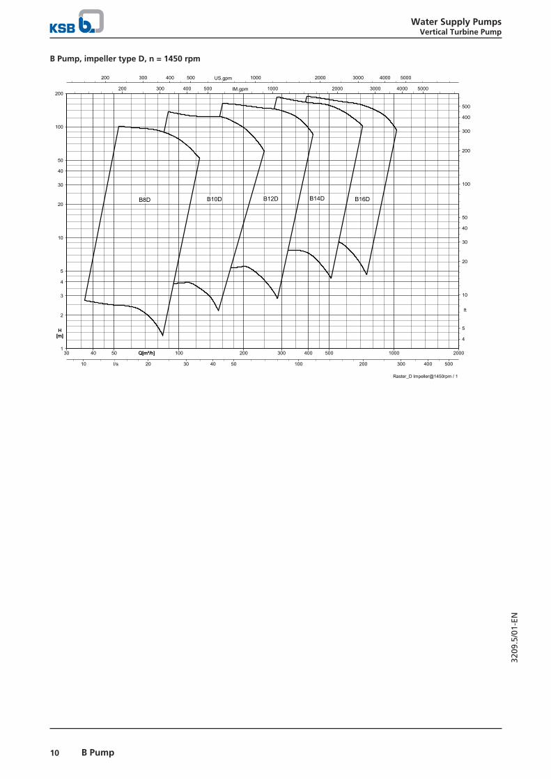
B Pump, impeller type D, n = 1450 rpm
Raster_D Impeller@1450rpm / 1
H[m]
Q[m³/h]30 40 50 100 200 300 400 500 1000 2000Q[m³/h]
200 300 400 500 1000 2000 3000 4000 5000US.gpm
200 300 400 500 1000 2000 3000 4000 5000IM.gpm
1
2
3
4
5
10
20
30
40
50
100
200
H[m] 4
5
10
20
30
40
50
100
200
300
400
500
ft
10 20 30 40 50 100 200 300 400 500l/s
D8B D01B D21B D41B D61B

Water Supply PumpsVertical Turbine Pump
11B Pump
3209
.5/0
1-EN
B Pump, impeller type F, n = 1450 rpm
Raster_F Impeller @1450rpm / 1
H[m]
Q[m³/h]100 200 300 400 50090 700Q[m³/h]
400 500 1000 2000 3000US.gpm
400 500 1000 2000IM.gpm
2
3
4
5
10
20
30
40
50
100
200
H[m]
10
20
30
40
50
100
200
300
400
500
ft
30 40 50 100l/s
F01B
F21B

Water Supply PumpsVertical Turbine Pump
12 B Pump
3209
.5/0
1-EN
B Pump, impeller type B, n = 980 rpm
Raster_B Impeller @960rpm / 1
H[m]
Q[m³/h]100 200 300 400 500 1000 2000Q[m³/h]
500 1000 2000 3000 4000 5000US.gpm
400 500 1000 2000 3000 4000 5000IM.gpm
3
4
5
10
20
30
40
50
100
200
H[m]
10
20
30
40
50
100
200
300
400
500
ft
30 40 50 100 200 300 400 500l/s
B81B B02B B22B B42B

Water Supply PumpsVertical Turbine Pump
13B Pump
3209
.5/0
1-EN
Characteristic curves
n = 2900 rpm
B6B, n = 2900 rpm
siddmuh1/10857982/0
10 20 30 40 50 60Q [m³/h]
50 100 150 200 250Q [US.gpm]
50 100 150 200Q [IM.gpm]
4
6
8
10
12
14
H [m]
20
40
H [ft]
5 10 15Q [l/s]
5
2
7NPSH3 [m] 20
10
NPSH3 [ft]
0.5
1.0
1.5
2.0
P [kW]
1
2
P [hp]
10 20 30 40 50 60Q [m³/h]
ø109
ø109
ø104
ø104
ø99
ø99
ø94
ø94
ø89
ø89
ø84
ø84

Water Supply PumpsVertical Turbine Pump
14 B Pump
3209
.5/0
1-EN
B7B, n = 2900 rpm
siddmuh1/10868135/0
20 40 60 80 100 120Q [m³/h]
100 200 300 400 500Q [US.gpm]
100 200 300 400Q [IM.gpm]
5
10
15
20
H [m]
20
40
60
H [ft]
10 20 30Q [l/s]
0
15
NPSH3 [m]
0
40NPSH3 [ft]
2
3
4
5
P [kW]
2
4
6
P [hp]
20 40 60 80 100 120Q [m³/h]
ø132/127.5
ø132/127.5
ø126/122
ø126/122
ø122/118
ø122/118
ø118/114
ø118/114
ø114/110
ø114/110
ø110/106
ø110/106
ø106/102
ø106/102

Water Supply PumpsVertical Turbine Pump
15B Pump
3209
.5/0
1-EN
B8B, n = 2900 rpm
siddmuh1/10871037/0
40 60 80 100 120 140Q [m³/h]
200 300 400 500 600Q [US.gpm]
200 300 400 500Q [IM.gpm]
10
15
20
25
H [m]
40
60
80
H [ft]
10 20 30 40Q [l/s]
0
8
NPSH3 [m]
0
20NPSH3 [ft]
4
6
8
10
P [kW]
5
10
P [hp]
40 60 80 100 120 140Q [m³/h]
ø154/150
ø154/150
ø150/145
ø150/145
ø145/140
ø145/140
ø140/136
ø140/136
ø136/131
ø136/131
ø131/127
ø131/127
ø127/122
ø127/122
Water Supply PumpsVertical Turbine Pump
16 B Pump
3209
.5/0
1-EN
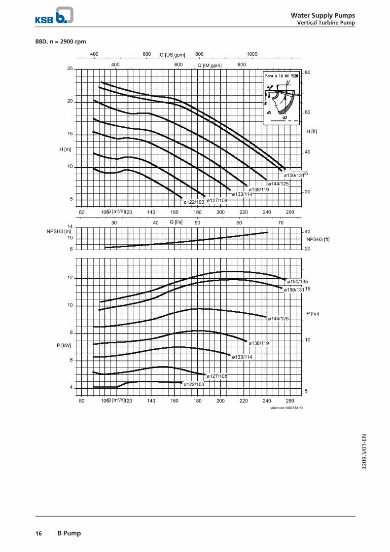
B8D, n = 2900 rpm
siddmuh1/10871841/0
80 100 120 140 160 180 200 220 240 260Q [m³/h]
400 600 800 1000Q [US.gpm]
400 600 800Q [IM.gpm]
5
10
15
20
25
H [m]
20
40
60
80
H [ft]
30 40 50 60 70Q [l/s]
10
6
14NPSH3 [m]
20
40NPSH3 [ft]
4
6
8
10
12
P [kW]
5
10
15
P [hp]
80 100 120 140 160 180 200 220 240 260Q [m³/h]
ø150/135
ø150/135
ø150/131
ø150/131
ø144/125
ø144/125
ø138/119
ø138/119
ø133/114
ø133/114
ø127/108
ø127/108
ø122/103
ø122/103
Water Supply PumpsVertical Turbine Pump
17B Pump
3209
.5/0
1-EN
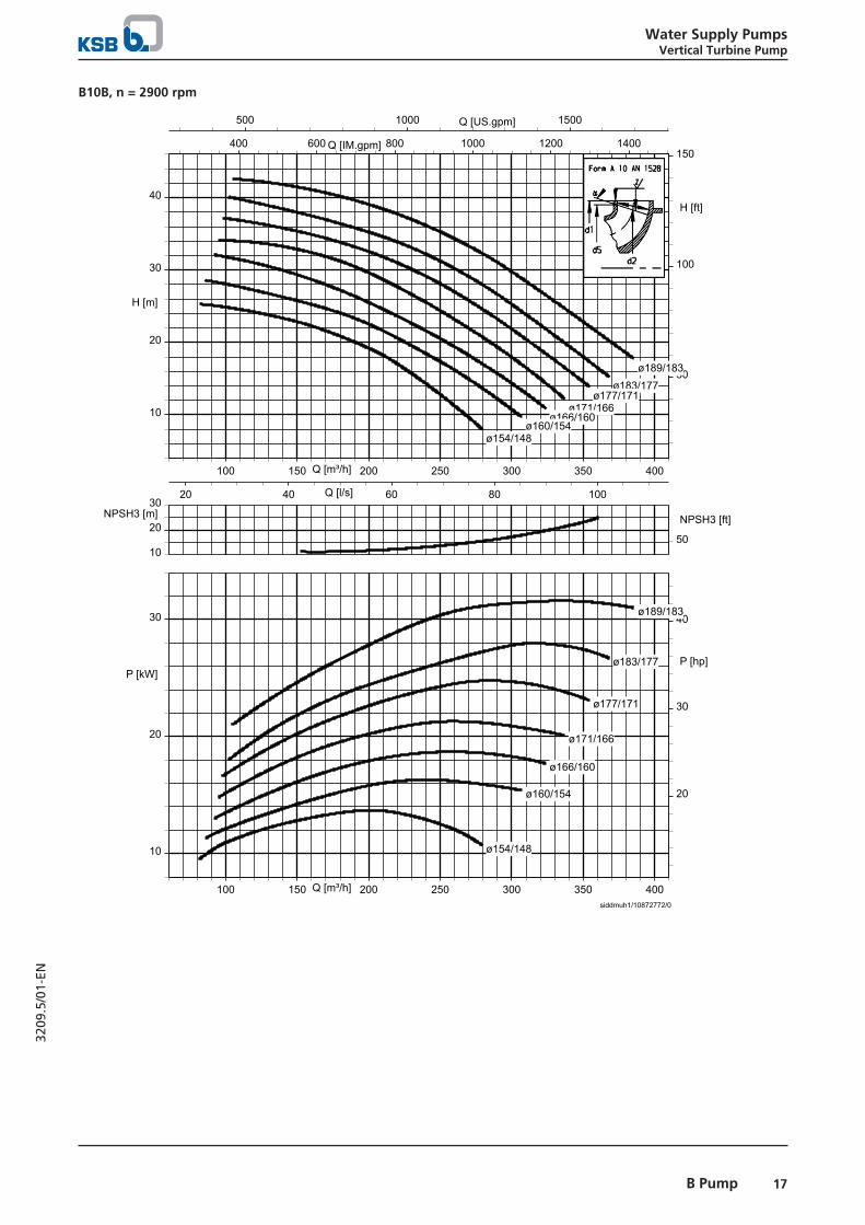
B10B, n = 2900 rpm
siddmuh1/10872772/0
100 150 200 250 300 350 400Q [m³/h]
500 1000 1500Q [US.gpm]
400 600 800 1000 1200 1400Q [IM.gpm]
10
20
30
40
H [m]
50
100
150
H [ft]
20 40 60 80 100Q [l/s]
20
10
30NPSH3 [m]
50
NPSH3 [ft]
10
20
30
P [kW]
20
30
40
P [hp]
100 150 200 250 300 350 400Q [m³/h]
ø189/183
ø189/183
ø183/177
ø183/177
ø177/171
ø177/171
ø171/166
ø171/166
ø166/160
ø166/160
ø160/154
ø160/154
ø154/148
ø154/148

Water Supply PumpsVertical Turbine Pump
18 B Pump
3209
.5/0
1-EN
B10D, n = 2900 rpm
siddmuh1/10873723/0
100 200 300 400 500Q [m³/h]
500 1000 1500 2000Q [US.gpm]
500 1000 1500 2000Q [IM.gpm]
10
20
30
40
H [m]
50
100
H [ft]
40 60 80 100 120 140Q [l/s]
20
5
30NPSH3 [m]
50NPSH3 [ft]
10
20
30
40
P [kW]
20
40
P [hp]
100 200 300 400 500Q [m³/h]
ø189/172.5
ø189/172.5
ø182/165
ø182/165
ø189/165
ø189/165
ø182/158
ø182/158
ø175/151
ø175/151
ø168/144
ø168/144
ø161/137
ø161/137
ø154/130
ø154/130

Water Supply PumpsVertical Turbine Pump
19B Pump
3209
.5/0
1-EN
n = 1450 rpm
B6B, n = 1450 rpm
siddmuh1/10874980/0
5 10 15 20 25 30Q [m³/h]
40 60 80 100 120Q [US.gpm]
20 40 60 80 100Q [IM.gpm]
1
2
3
H [m]
5
10
H [ft]
2 4 6 8Q [l/s]
2
2.8
NPSH3 [m]7
9NPSH3 [ft]
0.10
0.15
0.20
0.25
P [kW]
0.1
0.2
0.3
P [hp]
5 10 15 20 25 30Q [m³/h]
ø109/105
ø109/105
ø104/99
ø104/99
ø99/94
ø99/94
ø94/89
ø94/89
ø89/84
ø89/84
ø84/80
ø84/80

Water Supply PumpsVertical Turbine Pump
20 B Pump
3209
.5/0
1-EN
B7B, n = 1450 rpm
siddmuh1/10877236/0
10 20 30 40 50 60Q [m³/h]
50 100 150 200 250Q [US.gpm]
50 100 150 200Q [IM.gpm]
1
2
3
4
5
H [m]
5
10
15
H [ft]
5 10 15Q [l/s]
2
4
NPSH3 [m] 10
6
16
NPSH3 [ft]
0.2
0.4
0.6
P [kW]
0.4
0.6
0.8
P [hp]
10 20 30 40 50 60Q [m³/h]
ø132/127.5
ø132/127.5
ø126/122
ø126/122
ø122/118
ø122/118
ø118/114
ø118/114
ø114/110
ø114/110
ø110/106
ø110/106
ø106/102
ø106/102

Water Supply PumpsVertical Turbine Pump
21B Pump
3209
.5/0
1-EN
B8B, n = 1450 rpm
siddmuh1/10878236/0
20 40 60 80 100Q [m³/h]
100 200 300 400Q [US.gpm]
100 200 300Q [IM.gpm]
2
4
6
H [m]
10
20
H [ft]
5 10 15 20 25Q [l/s]5
2
NPSH3 [m]10
15NPSH3 [ft]
0.4
0.6
0.8
1.0
1.2
1.4
P [kW]1.0
1.5
P [hp]
20 40 60 80 100Q [m³/h]
ø154/150
ø154/150
ø150/145
ø150/145
ø145/140
ø145/140
ø140/136
ø140/136
ø136/131
ø136/131
ø131/127
ø131/127
ø127/122
ø127/122

Water Supply PumpsVertical Turbine Pump
22 B Pump
3209
.5/0
1-EN
B8D, n = 1450 rpm
siddmuh1/10878485/0
40 60 80 100 120Q [m³/h]
200 300 400 500Q [US.gpm]
200 300 400Q [IM.gpm]
1
2
3
4
5
6
H [m]
5
10
15
H [ft]
10 20 30Q [l/s]
4
2.5
5NPSH3 [m]
10
15NPSH3 [ft]
0.5
1.0
1.5
P [kW]
1.0
1.5
2.0
P [hp]
40 60 80 100 120Q [m³/h]
ø150/135
ø150/135
ø144/125
ø144/125
ø138/119
ø138/119
ø133/114
ø133/114
ø127/108
ø127/108
ø122/103
ø122/103

Water Supply PumpsVertical Turbine Pump
23B Pump
3209
.5/0
1-EN
B10B, n = 1450 rpm
siddmuh1/10878719/0
40 60 80 100 120 140 160 180 200Q [m³/h]
200 400 600 800Q [US.gpm]
200 400 600Q [IM.gpm]
2
4
6
8
10
H [m]
10
20
30
H [ft]
10 20 30 40 50Q [l/s]10
2
NPSH3 [m]
10
30NPSH3 [ft]
1
2
3
4
P [kW]
2
4
P [hp]
40 60 80 100 120 140 160 180 200Q [m³/h]
ø189/183
ø189/183
ø183/177
ø183/177
ø177/171
ø177/171
ø171/166
ø171/166
ø166/160
ø166/160
ø160/154
ø160/154
ø154/148
ø154/148

Water Supply PumpsVertical Turbine Pump
24 B Pump
3209
.5/0
1-EN
B10D, n = 1450 rpm
siddmuh1/10879010/0
50 100 150 200 250Q [m³/h]
400 600 800 1000Q [US.gpm]
200 400 600 800Q [IM.gpm]
2
4
6
8
10
H [m]
10
20
30
H [ft]
20 40 60Q [l/s]
2
8
NPSH3 [m]10
20NPSH3 [ft]
2
3
4
5
P [kW]
2
4
6
P [hp]
50 100 150 200 250Q [m³/h]
ø189/172.5
ø189/172.5
ø182/165
ø182/165
ø189/165
ø189/165
ø182/158
ø182/158
ø175/151
ø175/151
ø168/144
ø168/144
ø161/137
ø161/137
ø154/130
ø154/130

Water Supply PumpsVertical Turbine Pump
25B Pump
3209
.5/0
1-EN
B10F, n = 1450 rpm
siddmuh1/10879749/0
100 150 200 250 300 350Q [m³/h]
400 600 800 1000 1200 1400 1600Q [US.gpm]
400 600 800 1000 1200Q [IM.gpm]
2
4
6
8
H [m]
10
20
H [ft]
40 60 80 100Q [l/s]
4
6
NPSH3 [m]
20
12
NPSH3 [ft]
2
3
4
5
6
P [kW]
4
6
8
P [hp]
100 150 200 250 300 350Q [m³/h]
ø189/160
ø189/160
ø183/154
ø183/154
ø177/148
ø177/148
ø171/142
ø171/142
ø165/136
ø165/136
ø160/130
ø160/130

Water Supply PumpsVertical Turbine Pump
26 B Pump
3209
.5/0
1-EN
B12B, n = 1450 rpm
siddmuh1/10880290/0
100 150 200 250 300 350Q [m³/h]
400 600 800 1000 1200 1400 1600Q [US.gpm]
400 600 800 1000 1200Q [IM.gpm]
5
10
15
H [m]
20
40
H [ft]
20 40 60 80 100Q [l/s]10
2
NPSH3 [m]
10
30NPSH3 [ft]
60
70
80
Eta [%]
5
10
P [kW] 10
4
16
P [hp]
100 150 200 250 300 350Q [m³/h]
ø236/226
ø236/226
ø236/226
ø230/220
ø230/220
ø230/220
ø224/214
ø224/214
ø224/214
ø218/208
ø218/208
ø218/208
ø212/202
ø212/202
ø212/202
ø206/196
ø206/196
ø206/196
ø200/190
ø200/190
ø200/190
ø194/184
ø194/184
ø194/184
ø188/178
ø188/178
ø188/178
ø182/172
ø182/172
ø182/172
ø176/166
ø176/166
ø176/166

Water Supply PumpsVertical Turbine Pump
27B Pump
3209
.5/0
1-EN
B12D, n = 1450 rpm
siddmuh1/10882231/0
100 150 200 250 300 350 400 450Q [m³/h]
500 1000 1500Q [US.gpm]
400 600 800 1000 1200 1400 1600Q [IM.gpm]
2
4
6
8
10
12
14
H [m]
20
40
H [ft]
40 60 80 100 120Q [l/s]
5
8NPSH3 [m] 20
NPSH3 [ft]
4
6
8
10
12
P [kW]
5
10
15
P [hp]
100 150 200 250 300 350 400 450Q [m³/h]
ø227/205
ø227/205
ø215/194
ø215/194
ø227/194
ø227/194
ø205/184
ø205/184
ø185/175
ø185/175
ø195/175
ø195/175
ø180/160
ø180/160

Water Supply PumpsVertical Turbine Pump
28 B Pump
3209
.5/0
1-EN
B12F, n = 1450 rpm
siddmuh1/10882580/0
200 300 400 500 600Q [m³/h]
1000 1500 2000 2500Q [US.gpm]
500 1000 1500 2000Q [IM.gpm]
4
6
8
10
12
H [m]
10
20
30
40
H [ft]
50 100 150Q [l/s]10
6
NPSH3 [m]
20
30NPSH3 [ft]
5
10
15
P [kW]
10
15
20
P [hp]
200 300 400 500 600Q [m³/h]
ø235/200
ø235/200
ø228/193
ø228/193
ø221/186
ø221/186
ø214/179
ø214/179
ø207/172
ø207/172
ø199/164
ø199/164
ø193/157
ø193/157

Water Supply PumpsVertical Turbine Pump
29B Pump
3209
.5/0
1-EN
B14B, n = 1450 rpm
siddmuh1/10903236/0
100 200 300 400 500Q [m³/h]
500 1000 1500 2000Q [US.gpm]
500 1000 1500 2000Q [IM.gpm]
5
10
15
20
H [m]
20
40
60
H [ft]
40 60 80 100 120 140Q [l/s]
10
2
NPSH3 [m] 20NPSH3 [ft]
5
10
15
20
25
P [kW]
10
20
30
P [hp]
100 200 300 400 500Q [m³/h]
ø276/268
ø276/268
ø268/260
ø268/260
ø260/252
ø260/252
ø252/243
ø252/243
ø243/235
ø243/235
ø235/227
ø235/227
ø227/219
ø227/219
ø219/211
ø219/211
ø211/203
ø211/203
ø203/195
ø203/195

Water Supply PumpsVertical Turbine Pump
30 B Pump
3209
.5/0
1-EN
B14D, n = 1450 rpm
siddmuh1/10910042/0
200 300 400 500 600 700Q [m³/h]
1000 1500 2000 2500 3000Q [US.gpm]
1000 1500 2000 2500Q [IM.gpm]
5
10
15
20
H [m]
20
40
60
H [ft]
50 100 150 200Q [l/s]
5
10
NPSH3 [m]
20
10
30
NPSH3 [ft]
10
15
20
25
30
P [kW]
20
30
40
P [hp]
200 300 400 500 600 700Q [m³/h]
ø268/242
ø268/242
ø258/224
ø258/224
ø248/214
ø248/214
ø238/204
ø238/204
ø228/194
ø228/194
ø218/184
ø218/184

Water Supply PumpsVertical Turbine Pump
31B Pump
3209
.5/0
1-EN
B16D, n = 1450 rpm
siddmuh1/10961020/0
200 400 600 800 1000Q [m³/h]
1000 2000 3000 4000Q [US.gpm]
1000 2000 3000 4000Q [IM.gpm]
5
10
15
20
25
H [m]
20
40
60
80
H [ft]
100 150 200 250 300Q [l/s]
0
1000
NPSH3 [m]
0
2000NPSH3 [ft]
20
30
40
50
P [kW]
40
60
P [hp]
200 400 600 800 1000Q [m³/h]
ø303/273.5
ø303/273.5
ø285/258
ø285/258
ø295/258
ø295/258
ø303/258
ø303/258
ø272/245
ø272/245
ø272/232
ø272/232
ø259/219
ø259/219
ø246/212
ø246/212

Water Supply PumpsVertical Turbine Pump
32 B Pump
3209
.5/0
1-EN
B18B, n = 1450 rpm
siddmuh1/10963959/0
400 600 800 1000 1200Q [m³/h]
2000 3000 4000 5000Q [US.gpm]
1000 2000 3000 4000Q [IM.gpm]
10
20
30
40
H [m]
50
100
H [ft]
100 150 200 250 300Q [l/s]
0
20
NPSH3 [m]
0
50NPSH3 [ft]
20
40
60
80
100
P [kW]
50
100
P [hp]
400 600 800 1000 1200Q [m³/h]
ø354/343
First Stage Impeller Standard Impeller
ø354/343
ø330/320
ø330/320
ø320/310
ø320/310
ø310/300
ø310/300
ø300/290
ø300/290
ø290/280
ø290/280
ø270/260
ø270/260

Water Supply PumpsVertical Turbine Pump
33B Pump
3209
.5/0
1-EN
B20B, n = 1450 rpm
siddmuh1/11044011/0
400 600 800 1000 1200 1400 1600Q [m³/h]
2000 4000 6000Q [US.gpm]
2000 3000 4000 5000Q [IM.gpm]
10
20
30
40
50
H [m]
50
100
150
H [ft]
100 200 300 400Q [l/s]
5
10
NPSH3 [m]
20
40
NPSH3 [ft]
50
100
150
P [kW]
100
200
P [hp]
400 600 800 1000 1200 1400 1600Q [m³/h]
ø390/378
ø390/378
ø390/378
ø390/378
ø366/355
ø366/355
ø355/343
ø355/343
ø343/332
ø343/332
ø320/309
ø320/309
ø298/286
ø298/286

Water Supply PumpsVertical Turbine Pump
34 B Pump
3209
.5/0
1-EN
B22B, n = 1450 rpm
siddmuh1/11043539/0
3000 4000 5000 6000 7000 8000 9000 10000Q [US.gpm]
1000 1500 2000Q [m³/h]
200 300 400 500 600Q [l/s]
50
100
150
H [ft]
20
40
H [m]
4000 6000 8000Q [IM.gpm]50
10
NPSH3 [ft]5
15
NPSH3 [m]
50
100
150
200
250
P [hp]
50
100
150
200
P [kW]
3000 4000 5000 6000 7000 8000 9000 10000Q [US.gpm]
ø416/402
ø416/402
ø402/389
ø402/389
ø399/376
ø399/376
ø389/353
ø389/353
ø368/327
ø368/327
ø352/300
ø352/300
ø340/275
ø340/275
ø329/249
ø329/249

Water Supply PumpsVertical Turbine Pump
35B Pump
3209
.5/0
1-EN
B24B, n = 1450 rpm
siddmuh1/11043715/0
1200 1400 1600 1800 2000 2200 2400 2600Q [m³/h]
6000 8000 10000 12000Q [US.gpm]
6000 8000 10000Q [IM.gpm]
30
40
50
60
70
H [m]
100
150
200
H [ft]
400 500 600 700Q [l/s]
10
20
NPSH3 [m] 50
10
NPSH3 [ft]
200
300
400
500
P [kW]
400
600
P [hp]
1200 1400 1600 1800 2000 2200 2400 2600Q [m³/h]
ø488/470
ø488/470
ø488/470
ø488/470
ø475/454
ø475/454
ø462/440
ø462/440
ø445/424
ø445/424
ø432/412
ø432/412
ø420/400
ø420/400

Water Supply PumpsVertical Turbine Pump
36 B Pump
3209
.5/0
1-EN
n = 980 rpm
B18B, n = 980 rpm
B18B@960 st1/1
100 200 300 400 500 600 700 800m³/h
000300020001 US.gpm
000300020001 IM.gpm
6
8
10
12
14
16
18
m
20
40
ft
50 100 150 200l/s
4
6
8
20
10
ft
10
20
30
20
40
hp
100 200 300 400 500 600 700 800m³/h
343/453ø
343/453ø
023/033ø
023/033ø
013/023ø
013/023ø
003/013ø
003/013ø
092/003ø
092/003ø
082/092ø
082/092ø
062/072ø
062/072ø
H [m]
NPSH3 [m]
P [kW]

Water Supply PumpsVertical Turbine Pump
37B Pump
3209
.5/0
1-EN
B20B, n = 980 rpm
siddmuh1/11044144/0
200 400 600 800 1000Q [m³/h]
1000 2000 3000 4000Q [US.gpm]
1000 2000 3000 4000Q [IM.gpm]
5
10
15
20
H [m]
20
40
60
H [ft]
100 150 200 250 300Q [l/s]
5
10
NPSH3 [m]
20
10
30
NPSH3 [ft]
20
40
P [kW]
20
40
60
P [hp]
200 400 600 800 1000Q [m³/h]
ø390/378
Standard Impeller
First Stage Impeller
ø390/378
ø366/355
ø366/355
ø355/343
ø355/343
ø343/332
ø343/332
ø320/309
ø320/309
ø298/286
ø298/286

Water Supply PumpsVertical Turbine Pump
38 B Pump
3209
.5/0
1-EN
B22B, n = 980 rpm
siddmuh1/11044302/0
600 800 1000 1200 1400Q [m³/h]
2000 3000 4000 5000 6000Q [US.gpm]
2000 3000 4000 5000Q [IM.gpm]
5
10
15
20
H [m]
20
40
60
H [ft]
200 300 400Q [l/s]
4
6
8
NPSH3 [m]
20
10
NPSH3 [ft]
20
40
60
P [kW]
20
40
60
80
P [hp]
600 800 1000 1200 1400Q [m³/h]
ø416/402
Standard Impeller
Fisrt Stage Impeller
ø416/402
ø402/389
ø402/389
ø399/376
ø399/376
ø389/353
ø389/353
ø368/327
ø368/327
ø352/300
ø352/300
ø340/275
ø340/275
ø329/249
ø329/249

Water Supply PumpsVertical Turbine Pump
39B Pump
3209
.5/0
1-EN
B24B, n = 980 rpm
siddmuh1/11044485/0
800 1000 1200 1400 1600 1800Q [m³/h]
4000 6000 8000Q [US.gpm]
3000 4000 5000 6000 7000Q [IM.gpm]
15
20
25
30
H [m]
40
60
80
100
H [ft]
200 300 400 500Q [l/s]
5
10
NPSH3 [m]
20
10
35
NPSH3 [ft]
60
80
100
120
140
P [kW]
100
150
P [hp]
800 1000 1200 1400 1600 1800Q [m³/h]
ø488/470
Standard Impeller
First Stage Impeller
ø488/470
ø475/454
ø475/454
ø462/440
ø462/440
ø445/424
ø445/424
ø432/412
ø432/412
ø420/400
ø420/400

Water Su
pp
ly Pum
ps
Vertical Tu
rbin
e Pum
p
40B
Pum
p
3209.5/01-EN
Dimensions and weights
Pump dimensions
Pump dimensions
Size
Imp
elle
r ty
pe
Max. number of stages Stage length
Len
gth
of
each
add
itio
nal
sta
ge Max. length
Dia
met
er
Suction strainerlength
Co
lum
n p
ipe
dia
met
er
Min
.su
bm
erg
ence
of
firs
t-st
age
imp
elle
r
Suct
ion
str
ain
erd
iam
eter
Foo
t va
lve
len
gth
Min
. cle
aran
ceb
etw
een
suct
ion
str
ain
eran
d f
loo
r
980
rpm
1450
rp
m
2900
rp
m
Flan
ged
con
nec
tio
n
Thre
aded
con
nec
tio
n
Flan
ged
con
nec
tio
n
Thre
aded
con
nec
tio
n
Flan
ged
con
nec
tio
n
Thre
aded
con
nec
tio
n
[mm] [mm] [mm] [mm] [mm] [mm] [mm] [mm] [inch] [mm] [inch] [mm] [mm]
B6 B - 25 16 380 435 100 2780 2825 140 190 235 3, 4 300 4 135 100B7 B - 21 10 445 500 120 2845 2890 165 190 235 3, 4 300 4 135 100B8 B - 18 8 480 535 140 2860 2905 190 230 275 4, 5 350 5 165 125
D - 18 12 480 535 140 2860 2905 190 230 275 5, 6 350 5 165 125B10 B - 15 5 535 590 165 2845 2890 240 260 315 5, 6 400 6 185 150
D - 15 7 535 590 165 2845 2890 240 260 315 6, 7 400 6 185 150F - 9 - 630 675 255 2830 2675 240 260 315 7 400 6 185 150
B12 B - 12 - 580 625 200 2780 2875 290 295 310 7, 8 450 7 270 175D - 12 - 580 625 200 2780 2875 290 295 310 8, 10 450 7 270 175F - 8 - 745 745 300 2845 2845 290 340 390 10 450 8 365 200
B14 B - 10 - 610 655 235 2725 2770 338 340 390 8, 10 450 8 365 200D - 10 - 610 655 235 2725 2770 338 340 390 10 450 8 365 200
B16 D - 8 - 690 735 270 2580 - 390 355 470 10, 12 450 10 410 250B18 B 7 7 - 890 - 300 2690 - 430 540 540 12, 14 500 12 490 300B20 B 6 6 - 955 - 335 2630 - 472 - 650 14, 16 500 14 560 350B22 B 5 5 - 1050 - 400 2650 - 560 722 730 16, 18 500 16 600 400B24 B 5 5 - 1050 - 410 2700 - 600 722 730 18, 20 500 16 630 400

Water Supply PumpsVertical Turbine Pump
41B Pump
3209
.5/0
1-EN
Discharge nozzle dimensions
g
b
f
eDNd
dh
Ø
DNst
1
2
A - A
A
A
Fig. 1: Discharge nozzle dimensions VN 1342, 1342A, 1830 and 2030
1 Foundation bolt 2 Grout after pump installation.
1
2A
A
f
h
e
NWd d
DNst
gb
3 4X
A - A X
Fig. 2: Discharge nozzle dimensions VN 2541 and 2541A
1 Foundation bolt 2 Grout after pump installation.3 Washer 4 Discharge casing
A
Ag
b
1
2
A - A
e
ØDNd
d
f
h
DNst
Fig. 3: Discharge nozzle dimensions VN 3051
1 Foundation bolt 2 Grout after pump installation.

Water Supply PumpsVertical Turbine Pump
42 B Pump
3209
.5/0
1-EN
Discharge nozzle dimensions
Discharge head b d e f h g DNst Shaftdiameter
DNd Foundation bolt Material
[mm] [mm] [mm] [mm] [mm] [mm] [mm] [mm] [mm]
VN 1342A 425
As
per
fla
ng
est
and
ard
148 210 297 350 75, 100 25, 30, 35 100 M16 × 250 Grey cast iron
VN 1342 425 148 210 297 350 100, 125 25, 30, 35 125 M16 × 250 Grey cast iron
VN 1830 425 148 210 297 350 150, 175 25, 30, 35 150 M16 × 250 Grey cast iron
VN 2030 440 171,5 200 400 370 175, 200 25, 30, 35 200 M16 × 250 Grey cast iron
VN 2541A 600 225 290 470 430 200 25, 30, 35, 45 200 M16 × 300 Grey cast iron
VN 2541 600 225 290 470 430 250 30, 35, 45 250 M16 × 300 Grey cast iron
VN 3051 700 290 305 570 600 200, 250 30, 35, 45 300 M20 × 250 Steel
Weights
Bowl assembly
Weight of bowl assembly depending on size and number of stages
Size
Number of stages
1 2 3 4 5 6 7 8 9 10 11 12 13 14 15 16 17 18 19 20 21 22 23 24 25
Weight of bowl assembly
[kg] [kg] [kg] [kg] [kg] [kg] [kg] [kg] [kg] [kg] [kg] [kg] [kg] [kg] [kg] [kg] [kg] [kg] [kg] [kg] [kg] [kg] [kg] [kg] [kg]
B6 22 28 34 40 46 52 58 64 70 76 82 88 94 100 106 112 118 124 130 136 142 148 154 160 166
B7 32 41 50 59 68 77 86 95 104 113 122 131 140 149 158 167 176 185 194 203 212 - - - -
B8 44 56 68 80 92 104 116 128 140 152 164 176 188 200 212 224 236 248 - - - - - - -
B10 72 96 120 144 168 192 216 240 264 288 312 336 360 384 408 - - - - - - - - - -
B12 112 154 195 238 280 322 364 406 448 490 532 574 - - - - - - - - - - - - -
B14 160 222 284 346 408 470 532 594 686 718 - - - - - - - - - - - - - - -
B16 220 305 390 475 560 645 730 815 - - - - - - - - - - - - - - - - -
B18 295 407 519 631 743 855 967 - - - - - - - - - - - - - - - - - -
B20 385 545 705 865 1025 1185 - - - - - - - - - - - - - - - - - - -
B22 530 785 1040 1295 1560 - - - - - - - - - - - - - - - - - - - -
B24 640 940 1240 1540 1840 - - - - - - - - - - - - - - - - - - - -

Water Supply PumpsVertical Turbine Pump
43B Pump
3209
.5/0
1-EN
Column pipe set
Flanged connectionA standard column pipe set comprises:1 column pipe with 2 flanges1 bearing spider with bearing bush1 intermediate shaft with bearing sleeve1 intermediate shaft coupling1 set of fastening bolts/screws and O-rings
An upper column pipe set comprises:1 column pipe with 2 flanges1 intermediate shaft coupling1 set of fastening bolts/screws and O-rings
Threaded connectionA standard column pipe set comprises:1 column pipe with bearing bush1 intermediate shaft coupling1 set of fastening bolts/screws and O-rings
An upper column pipe set comprises:1 column pipe with 1 flanged end and 1 threaded end - max. length: 1220 mm1 intermediate shaft coupling1 set of fastening bolts/screws and O-rings
Weight of column pipe set, flanged version 3) [kg]
Shaft diameter [mm] Column pipe set Column pipe diameter [mm]
80 100 125 150 200 250 300 350 400
20 1525 21,7 26,7 31,8 - - - - - -2000 35,5 33,0 39,3 - - - - - -2700 43,0 42,2 50,4 - - - - - -3050 46,8 46,8 55,9 - - - - - -
25 1525 - 26,7 34,7 58,6 80,1 - - - -2000 - 33,0 42,9 72,5 97,7 - - - -2700 - 42,2 54,9 92,9 123,7 - - - -3050 - 46,8 61,0 103,1 136,6 - - - -
30 1525 - - 37,1 61,5 83,4 117,6 - - -2000 - - 46,1 76,2 101,9 142,4 - - -2700 - - 59,4 97,9 129,1 178,9 - - -3050 - - 66,1 108,7 142,7 197,1 - - -
35 1525 - - - 64,1 88,3 115,8 148,6 - -2000 - - - 79,7 107,6 141,4 181,4 - -2700 - - - 102,6 136,1 179,1 229,7 - -3050 - - - 114,0 150,3 197,9 253,9 - -
45 1525 - - - - 96,9 127,1 157,1 - -2000 - - - - 118,6 155,1 192,4 - -2700 - - - - 150,7 195,4 244,3 - -3050 - - - - 166,7 217,1 270,3 - -
60 1525 - - - - - - 174,4 231,2 303,32000 - - - - - - 191,4 251,8 328,92700 - - - - - - 246,9 319,1 412,83050 - - - - - - 268,5 345,3 445,3
70 1525 - - - - - - 183,5 240,3 312,52000 - - - - - - 212,8 275,9 356,72700 - - - - - - 256,0 328,2 421,93050 - - - - - - 277,6 354,4 454,4
3 Weight of threaded version = flanged version -10 %

Water Supply PumpsVertical Turbine Pump
44 B Pump
3209
.5/0
1-EN
Discharge head
Discharge head type VN without drive lantern
Discharge head Weight
[kg]
VN 1342A 87VN 1342 84VN 1830 80VN 2030 88
VN 2541A 165VN 2541 165VN 3051 170
Pump rotor
Weight of pump rotor
Size 1st stage Each additional stage
[kg] [kg]
B6 2,4 1,2B7 3,8 1,8B8 5,6 2,8B10 10,3 4,9B12 17,2 8,4B14 29,1 15,1B16 38,5 21,7B18 54 30,5B20 67 41B22 80 52B24 94 63
Weights of shaft enclosing tube, thrust bearing assembly, drive lantern and bearings on request.
Spare parts stock
Ordering spare partsAlways quote the following data when ordering replacementor spare parts:
▪ Order number
▪ Order item number
▪ Type series
▪ Material variant
Refer to the name plate for all data.
Also specify the following data:
▪ Part number and description (ð Page 47)
▪ Quantity of spare parts
▪ Shipping address
▪ Mode of dispatch (freight, mail, express freight, airfreight)

Water Supply PumpsVertical Turbine Pump
45B Pump
3209
.5/0
1-EN
Recommended spare parts stock for 2 years' operation to DIN 24296
Quantity of spare parts for recommended spare parts stock
Part No. Description Quantity Note
211 Pump shaft 1212 Intermediate shaft Z213 Top shaft 1230 Impeller 1271.1 Sand guard 1271.2 Sand guard -320 Rolling element bearing -321 Radial ball bearing -382.1 Bearing carrier 1384 Thrust collar 1400.1 Gasket 1400.2 Gasket S400.3 Gasket 1400.4 Gasket 2400.5 Gasket 1412.1 O-ring 1422.1 Felt ring -422.2 Felt ring -461 Gland packing (in metres) -502 Casing wear ring S521 Stage sleeve S-1 From size B14524 Shaft protecting sleeve 1 If applicable526 Centring sleeve -529 Bearing sleeve 1540 Bush 1541 Interstage bush S-1 Cannot be used for sizes B6, B7, B14 and above52-1 Clamping sleeve, complete S Up to and including size B12544 Threaded bush 1545.1 Bearing bush 1545.2 Bearing bush / rubber S545.3 Bearing bush 1851 Conical coupling -852 Screwed coupling Z + 1920.1 Nut with two flats - From size B14931.1 Lock washer - From size B14931.2 Lock washer -

Water Supply PumpsVertical Turbine Pump
46 B Pump
3209
.5/0
1-EN
Installation depths
Possible column pipe connections
Symbols key
Symbol Description
✘ Combination possible- Not available
Possible column pipe connections
Size Threaded connection [Zoll] Flanged connection [mm]
3 4 5 6 7 8 10 12 14 80 100 125 150 175 200 250 300 350 400 500
B6B ✘ ✘ - - - - - - - ✘ ✘ - - - - - - - - -B7B - ✘ ✘ - - - - - - - ✘ ✘ - - - - - - - -B8B - ✘ ✘ - - - - - - - ✘ ✘ - - - - - - - -B8D - - ✘ ✘ - - - - - - - ✘ ✘ - - - - - - -B10B - - ✘ ✘ - - - - - - - ✘ ✘ - - - - - - -B10D - - - ✘ ✘ - - - - - - - ✘ ✘ - - - - - -B10F - - - - ✘ - - - - - - - - ✘ - - - - - -B12B - - - - ✘ ✘ - - - - - - - ✘ ✘ - - - - -B12D - - - - - ✘ ✘ ✘ - - - - - - - ✘ - - - -B12F - - - - - - - ✘ ✘ - - - - - ✘ ✘ - - - -B14B - - - - - - ✘ ✘ ✘ - - - - - ✘ ✘ - - - -B14D - - - - - - - ✘ ✘ - - - - - - ✘ - - -B16D - - - - - - - - - - - - - - - ✘ ✘ - - -B18B - - - - - - - - - - - - - - - - - ✘ - -B20B - - - - - - - - - - - - - - - - - ✘ ✘ -B22B - - - - - - - - - - - - - - - - - ✘ ✘ -B24B - - - - - - - - - - - - - - - - - - ✘ ✘

Water Supply PumpsVertical Turbine Pump
47B Pump
3209
.5/0
1-EN
General drawings with list of components
Sectional drawing with list of components
13-17561
916400.1
230
112
107
711.1
544758
106
502
711.2
89-4901.8901.7
75-3.1733.1710.1
636.1710.2145.1731.1
144
529.1400.2(148 Nm)920.1902.1
920.12901.9
920.5902.2400.4
341
529.2
904.1271
940.2
554914.281-92
331
211
(7.3 Nm)
852.1
920.2901.1
(148 Nm)
400.3
920.3901.2
(290 Nm)
412.1
212
920.4901.3
(290 Nm)
412.2
(290 Nm)
213
636.2710.3145.2731.2
920.9902.6
(290 Nm)
920.11902.7
(290 Nm)
898
75-3.2
550
901.6
894591
(290 Nm)
733.2710.4731.5731.4731.313-18
754
902.4
(148 Nm)920.7
903.1411.1903.2411.2
AB
C
D
400.6
931930595840
904.2(59.9 Nm)920.10(148 Nm)
866
711.3
Fig. 4: Sectional drawing with list of components

Water Supply PumpsVertical Turbine Pump
48 B Pump
3209
.5/0
1-EN
545.1
531
541
AFig. 5: Detail A
545.2
383
524
852.2
B
Fig. 6: Detail B
C
451.1
400.5451.2
452461
545.3901.4(34.8 Nm)
914.1(17.7 Nm)
920.6(59.9 Nm)
902.3
903.3411.3
Fig. 7: Detail C
350
320505
940.1
932
360901.5
(148 Nm)
924
914.3(7.3 Nm) 902.5
(59.9 Nm)920.8
903.4411.4
D
Fig. 8: Detail D

Water Supply PumpsVertical Turbine Pump
49B Pump
3209
.5/0
1-EN
List of components
Part No. Description Part No. Description
13-17 Strainer 545.1/.2/.3 Bearing bush13-18 Elbow 554 Washer106 Suction casing 561 Grooved pin107 Discharge casing 591 Tank112 Pump bowl 595 Anti-vibration pad144 Discharge elbow 636.1/.2 Lubricating nipple145.1/.2 Adapter 75-3.1/3.2 Nozzle211 Pump shaft 710.1/.2/.3/.4 Pipe212 Intermediate shaft 711.1/.2/.3 Column pipe213 Top shaft 731.1/.2/.3/.4/.5 Pipe union230 Impeller 733.1/.2 Pipe clamp271 Sand guard 754 Valve ball320 Rolling element bearing 758 Screen331 Bearing pedestal 81-92 Cover plate341 Drive lantern 89-4 Shim350 Bearing housing 840 Coupling360 Bearing cover 852.1/.2 Screwed coupling383 Bearing spider 866 Coupling bolt400.1/.2/.3/.4/.5/.6 Gasket 894 Mounting bracket411.1/.2/.3/.4 Joint ring 898 Foundation block412.1/.2 O-ring 901.1/.2/.3/.4/.5/.6/.7/.8/.9 Hexagon head bolt451.1/.2 Stuffing box housing 902.1/.2/.3/.4/.5/.6/.7 Stud452 Gland follower 903.1/.2/.3/.4 Screw plug461 Gland packing 904.1/.2 Grub screw502 Casing wear ring 914.1/.2/.3 Hexagon socket head cap screw505 Loose collar 916 Plug524 Shaft protecting sleeve 920.1/.2/.3/.4/.5/.6/.7/.8/.9/
.10/.11/.12Nut
529.1/.2 Bearing sleeve 924 Adjusting nut531 Locking sleeve 930 Safety device541 Interstage bush 931 Lock washer550 Disc 932 Circlip544 Threaded bush 940.1/.2 Key

Water Supply PumpsVertical Turbine Pump
50 B Pump
3209
.5/0
1-EN
Bowl assembly
Flanged pump
13-17
544
758
916400
106
545
271
531320
541
902920
502
545
112
400
545
902920
271
107
211
901920
Fig. 9: Flanged pump
List of components
Part No. Description Part No. Description
13-17 Strainer 531 Locking sleeve106 Suction casing 541 Interstage bush107 Discharge casing 544 Threaded bush112 Pump bowl 545 Bearing bush211 Pump shaft 758 Screen271 Sand guard 901 Hexagon head bolt320 Rolling element bearing 902 Stud400 Gasket 916 Plug502 Casing wear ring 920 Nut

Water Supply PumpsVertical Turbine Pump
51B Pump
3209
.5/0
1-EN
Sectional drawing of sizes B18 to B24
748
106
545
502
320
541
940
112
521
107
545
Fig. 10: Sectional drawing of sizes 18 to 24
List of components
Part No. Description Part No. Description
106 Suction casing 521 Stage sleeve107 Discharge casing 541 Interstage bush112 Pump bowl 545 Bearing bush320 Rolling element bearing 748 Suction strainer502 Casing wear ring 940 Key
Water Supply PumpsVertical Turbine Pump
52 B Pump
3209
.5/0
1-EN
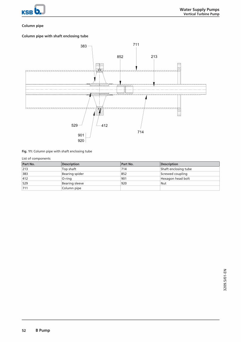
Column pipe
Column pipe with shaft enclosing tube
383
852
711
213
412529
901920
714
Fig. 11: Column pipe with shaft enclosing tube
List of components
Part No. Description Part No. Description
213 Top shaft 714 Shaft enclosing tube383 Bearing spider 852 Screwed coupling412 O-ring 901 Hexagon head bolt529 Bearing sleeve 920 Nut711 Column pipe

Water Supply PumpsVertical Turbine Pump
53B Pump
3209
.5/0
1-EN
Column pipe with flanged ends
213
711
545
901920
383
529
212
711
852
211
Fig. 12: Column pipe with flanged ends
List of components
Part No. Description Part No. Description
211 Pump shaft 545 Bearing bush212 Intermediate shaft 711 Column pipe213 Top shaft 852 Screwed coupling383 Bearing spider 901 Hexagon head bolt529 Bearing sleeve 920 Nut

Water Supply PumpsVertical Turbine Pump
54 B Pump
3209
.5/0
1-EN
Drive end
Lubricating device for shaft enclosing tube
144160
400
412568
591
Fig. 13: Lubricating device for shaft enclosing tube
List of components
Part No. Description Part No. Description
144 Pump shaft 412 O-ring160 Cover 591 Tank400 Gasket
Discharge casing for shaft enclosing tube
545107 521 714
412
A
Fig. 14: Discharge casing for shaft enclosing tube
List of components
Part No. Description Part No. Description
A Lubricant drain 545 Bearing bush107 Discharge casing 521 Stage sleeve412 O-ring 714 Shaft enclosing tube
Stuffing box housing for shaft enclosing tube
452
461
451
636
452
461458
451
Fig. 15: Stuffing box housing for shaft enclosing tube
List of components
Part No. Description Part No. Description
451 Stuffing box housing 461 Gland packing452 Gland follower 636 Lubricating nipple458 Lantern ring
Drive lantern with thrust bearing assembly
840
400
320350
400
Fig. 16: Drive lantern with thrust bearing assembly
List of components
Part No. Description Part No. Description
320 Rolling elementbearing
400 Gasket
350 Bearing housing 840 Coupling
Drive lantern with double bearing assembly
816
341
422
350
360
860861924321636320
213
Fig. 17: Drive lantern with double bearing assembly
List of components
Part No. Description Part No. Description
213 Top shaft 422 Felt ring320 Rolling element
bearing636 Lubricating nipple
321 Radial ball bearing 816 Stator tube

Water Supply PumpsVertical Turbine Pump
55B Pump
3209
.5/0
1-EN
Part No. Description Part No. Description
341 Drive lantern 860 Coupling part350 Bearing housing 861 Half coupling
Part No. Description Part No. Description
360 Bearing cover 924 Adjusting nut
Drive lantern with solid shaft and stuffing box housing
x
452
461
451
636451
854
940
901
160
421
360 341
861940924
526
914
320
350 451914902920
545711
901
145
452902920
144
902920
461Y
Fig. 18: Drive lantern with solid shaft and stuffing box housing
List of components
Part No. Description Part No. Description
144 Discharge elbow 545 Bearing bush145 Adapter 636 Lubricating nipple160 Cover 711 Column pipe320 Rolling element bearing 854 Backstop341 Drive lantern 861 Half coupling350 Bearing housing 901 Hexagon head bolt360 Bearing cover 902 Stud421 Lip seal 914 Hexagon socket head cap screw451 Stuffing box housing 920 Nut452 Gland follower 924 Adjusting nut461 Gland packing 940 Key526 Centring sleeve


KSB Pumps Company Limited16/2 Sir Aga Khan RoadLahore (Pakistan)UAN: +92-42-11-572-786Tel: +92-42-36304173-74Fax: +92-42-36366192, 36368878E-Mail: [email protected]
3209
.5/0
1-EN
25/0
1/20
21