Type 1047 / 1048 Construction Type 1049 / 1050 / 1051 Industrial ... · Adjustment protocol V4.7 A...
18
Service Manual Type 1047 / 1048 Construction Type 1049 / 1050 / 1051 Industrial 3.56.1 Adjustment protocol V4.7 A 924 C LI LHB/en/Edition: 03/2010 copyright by MJFCIFSS Adjustment protocol V4.7 A 924 C LI 1 Type 1047 / 1048 Construction Type 1049 / 1050 / 1051 Industrial Valid from serial number 39037 1.1 From software version V4.7 Date: Mechanic: Cust.: Type: Serial number: Operating hours: Check/adjustment Unit Setting Value measured during test Value measured after adjustment Location of adjustment Measuring point Machine-specific data Machine type Serial number Software versions Operating voltage Operating hours Diesel engine Low idle rpm rpm 900 +100 ....... High idle rpm rpm 1950 +50 ....... Operating conditions Oil temperature Warming up equipment C° > 50 +10 ....... .......
Transcript of Type 1047 / 1048 Construction Type 1049 / 1050 / 1051 Industrial ... · Adjustment protocol V4.7 A...

Service ManualType 1047 / 1048 Construction Type 1049 / 1050 / 1051 Industrial
3.56.1
Adjustment protocol V4.7 A 924 C LILH
B/e
n/E
ditio
n: 0
3/20
10
copyright by
MJFCIFSS
Adjustment protocol V4.7 A 924 C LI
1 Type 1047 / 1048 ConstructionType 1049 / 1050 / 1051 Industrial
Valid from serial number 39037
1.1 From software version V4.7
Date: Mechanic: Cust.:
Type: Serial number: Operating hours:
Check/adjustment Uni
t
Setti
ng
Valu
e m
easu
red
durin
g te
st
Valu
e m
easu
red
afte
r adj
ustm
ent
Loca
tion
of
adju
stm
ent
Mea
surin
g po
int
Machine-specific data
Machine type
Serial number
Software versions
Operating voltage
Operating hours
Diesel engine
Low idle rpm rpm 900 +100 .......
High idle rpm rpm 1950 +50 .......
Operating conditions
Oil temperatureWarming up equipment
C° > 50 +10 ....... .......

Adjustment protocol V4.7 A 924 C LI Service ManualType 1047 / 1048 Construction Type 1049 / 1050 / 1051 Industrial
LHB
/en/
Edi
tion:
03/
2010
3.56.2copyright by
MJFCIFSS
Pilot pressure
Preselect mode P.Adjustment at the valve 51
Pilot pressure bar 32 ±1 ...... ....... 51 49
Limit load control / flow reduction
Valves Y50 (LR) / Y51 (LS)
Adjustment in menu:In menu "set data", select "set control 2.1".
Check/adjustment Uni
t
Setti
ng
Valu
e m
easu
red
durin
g te
st
Valu
e m
easu
red
afte
r adj
ustm
ent
Loca
tion
of
adju
stm
ent
Mea
surin
g po
int
Service ManualType 1047 / 1048 Construction Type 1049 / 1050 / 1051 Industrial
3.56.3
Adjustment protocol V4.7 A 924 C LILH
B/e
n/E
ditio
n: 0
3/20
10
copyright by
MJFCIFSS
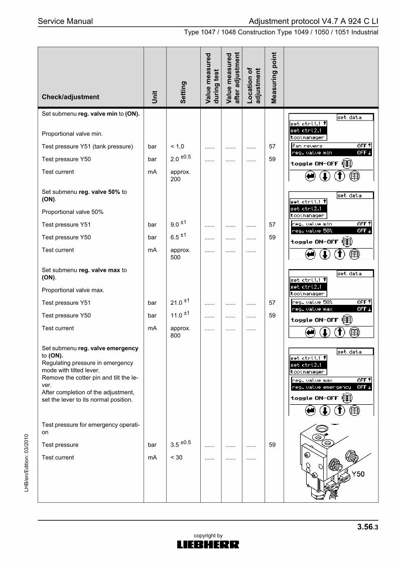
Set submenu reg. valve min to (ON).
Proportional valve min.
Test pressure Y51 (tank pressure) bar < 1,0 ...... ...... ...... 57
Test pressure Y50 bar 2.0 ±0.5 ...... ...... ...... 59
Test current mA approx. 200
Set submenu reg. valve 50% to (ON).
Proportional valve 50%
Test pressure Y51 bar 9.0 ±1 ...... ...... ...... 57
Test pressure Y50 bar 6.5 ±1 ...... ...... ...... 59
Test current mA approx. 500
...... ...... ......
Set submenu reg. valve max to (ON).
Proportional valve max.
Test pressure Y51 bar 21.0 ±1 ...... ...... ...... 57
Test pressure Y50 bar 11.0 ±1 ...... ...... ...... 59
Test current mA approx. 800
...... ...... ......
Set submenu reg. valve emergency to (ON).Regulating pressure in emergency mode with tilted lever. Remove the cotter pin and tilt the le-ver.After completion of the adjustment, set the lever to its normal position.
Test pressure for emergency operati-on
Test pressure bar 3.5 ±0.5 ...... ...... ...... 59
Test current mA < 30 ...... ...... ......
Check/adjustment Uni
t
Setti
ng
Valu
e m
easu
red
durin
g te
st
Valu
e m
easu
red
afte
r adj
ustm
ent
Loca
tion
of
adju
stm
ent
Mea
surin
g po
int

Adjustment protocol V4.7 A 924 C LI Service ManualType 1047 / 1048 Construction Type 1049 / 1050 / 1051 Industrial
LHB
/en/
Edi
tion:
03/
2010
3.56.4copyright by
MJFCIFSS
Hydraulic begin of regulation of the variable-displacement pump P1/P2
Adjustment in menu:In menu "set data", submenu "set control 2.1", set begin of reg. P1/P2 to (ON).
Check LR pressure.Tank pressure bar < 1,0 59
Double variable-displacement pump P1:
Reduce the pressure value of the secondary pressure-relief valve 261 (extending bucket cylinder)to a value below the begin of regula-tion, and then turn itin again until the control chamber pressure at the measuring point 44 begins to drop relative to 41.
Begin of regulation P1 bar 70 +2 ....... ....... 22.18
4144
Variable-displacement pump P2:
Reduce the pressure value of the secondary pressure-relief valve 261 (extending bucket cylinder)to a value below the begin of regula-tion, and then turn itin again until the control chamber pressure at the measuring point 43 begins to drop relative to 41.
Begin of regulation P2 bar 70 +2 ....... ....... 24.18
4143
Check/adjustment Uni
t
Setti
ng
Valu
e m
easu
red
durin
g te
st
Valu
e m
easu
red
afte
r adj
ustm
ent
Loca
tion
of
adju
stm
ent
Mea
surin
g po
int

Service ManualType 1047 / 1048 Construction Type 1049 / 1050 / 1051 Industrial
3.56.5
Adjustment protocol V4.7 A 924 C LILH
B/e
n/E
ditio
n: 0
3/20
10
copyright by
MJFCIFSS
Differential pressure ( -p)
Adjustment in menu:In menu "set data", submenu "set control 2.1", set deltaP P1/P2 to (ON).
Check MLS pressure. Tank pressure bar < 1,0 ....... ....... 57
With extend bucket cylinder function:Set the secondary pressure-relief valve 261 to 120-140 bar (at the measuring point 41).Read the differential pressure ( -p) between 41 (MP) and 45 (LS).
Differential pressure bar 30 +2 ....... ....... 2 4145
Check/adjustment Uni
t
Setti
ng
Valu
e m
easu
red
durin
g te
st
Valu
e m
easu
red
afte
r adj
ustm
ent
Loca
tion
of
adju
stm
ent
Mea
surin
g po
int

Adjustment protocol V4.7 A 924 C LI Service ManualType 1047 / 1048 Construction Type 1049 / 1050 / 1051 Industrial
LHB
/en/
Edi
tion:
03/
2010
3.56.6copyright by
MJFCIFSS
Output power of diesel engine (power test)
Note:Only carry out this test when you sus-pect problems (e.g. reduced power of diesel engine).Insert the service plug.Preselect mode P.
Lower the pressure value of the se-condary pressure-relief valves 242 (extending stick cylinder) and 261 (extending bucket cylinder) to a value below the test pressure.
Activate power test function at the display.
The fan is automatically set to nemer-gency.(I LR = 100%) - do not change.
Slowly increase the pressure value of the secondary pressure-relief valve 242 or 261 until the test value (guide value) is reached.
bar 135 -10 ....... ....... 242261
41
At test pressure, the speed of the die-sel engine may not drop below the ra-ted speed.
rpm 1800 +20 ....... .......
(read rpm on screen)Difference between measuring points.
bar < 10 ....... ....... 4144
41 - 44 (P1)41 - 43 (P2)
Check/adjustment Uni
t
Setti
ng
Valu
e m
easu
red
durin
g te
st
Valu
e m
easu
red
afte
r adj
ustm
ent
Loca
tion
of
adju
stm
ent
Mea
surin
g po
int

Service ManualType 1047 / 1048 Construction Type 1049 / 1050 / 1051 Industrial
3.56.7
Adjustment protocol V4.7 A 924 C LILH
B/e
n/E
ditio
n: 0
3/20
10
copyright by
MJFCIFSS
Pump valve
Preselect mode P.
Test pressure bar 45 - 60 ....... ....... 102 41
Measure check measurement X, if re-quired
(Q min. stop at variable-displacement pump)
mm approx. 27.0
....... ....... 102 X
Secondary pressure for working functions
Turn up the pressure cut-off valve101 screwed in(to max. 410 bar)Preselect mode P.
Note!For special attachments (e.g. verti-cally and horizontally adjustable boom), observe the instructions on the attached information signs, which refer to a reduced secondary pressu-re in the relevant control block sec-tions.
45
Check/adjustment Uni
t
Setti
ng
Valu
e m
easu
red
durin
g te
st
Valu
e m
easu
red
afte
r adj
ustm
ent
Loca
tion
of
adju
stm
ent
Mea
surin
g po
int
Adjustment protocol V4.7 A 924 C LI Service ManualType 1047 / 1048 Construction Type 1049 / 1050 / 1051 Industrial
LHB
/en/
Edi
tion:
03/
2010
3.56.8copyright by
MJFCIFSS
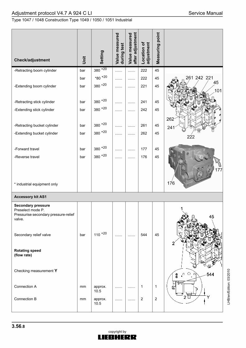
-Retracting boom cylinder bar 380 +20 ....... ....... 222 45
bar *80 +20 ....... ....... 222 45
-Extending boom cylinder bar 380 +20 ....... ....... 221 45
-Retracting stick cylinder bar 380 +20 ....... ....... 241 45
-Extending stick cylinder bar 380 +20 ....... ....... 242 45
-Retracting bucket cylinder bar 380 +20 ....... ....... 261 45
-Extending bucket cylinder bar 380 +20 ....... ....... 262 45
-Forward travel bar 380 +20 ....... ....... 177 45
-Reverse travel
* industrial equipment only
bar 380 +20 ....... ....... 176 45
Accessory kit AS1
Secondary pressurePreselect mode P.Pressurise secondary pressure-relief valve.
Secondary relief valve bar 110 +20 ....... ....... 544 45
Rotating speed(flow rate)
Checking measurement Y
Connection A mm approx. 10.5
....... ....... 1 1
Connection B mm approx. 10.5
....... ....... 2 2
Check/adjustment Uni
t
Setti
ng
Valu
e m
easu
red
durin
g te
st
Valu
e m
easu
red
afte
r adj
ustm
ent
Loca
tion
of
adju
stm
ent
Mea
surin
g po
int

Service ManualType 1047 / 1048 Construction Type 1049 / 1050 / 1051 Industrial
3.56.9
Adjustment protocol V4.7 A 924 C LILH
B/e
n/E
ditio
n: 0
3/20
10
copyright by
MJFCIFSS
Operating pressure (pressure cut-off)
Preselect mode P.
Operating pressurevia bucket cylinder function
bar 350 +10 ....... ....... 101 41
Check/adjustment Uni
t
Setti
ng
Valu
e m
easu
red
durin
g te
st
Valu
e m
easu
red
afte
r adj
ustm
ent
Loca
tion
of
adju
stm
ent
Mea
surin
g po
int
Adjustment protocol V4.7 A 924 C LI Service ManualType 1047 / 1048 Construction Type 1049 / 1050 / 1051 Industrial
LHB
/en/
Edi
tion:
03/
2010
3.56.10copyright by
MJFCIFSS
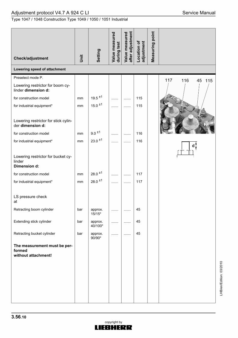
Lowering speed of attachment
Preselect mode P.
Lowering restrictor for boom cy-linder dimension d:
for construction model mm 19.5 ±1 ....... ....... 115
for industrial equipment* mm 15.0 ±1 ....... ....... 115
Lowering restrictor for stick cylin-der dimension d:
for construction model mm 9.0 ±1 ....... ....... 116
for industrial equipment* mm 23.0 ±1 ....... ....... 116
Lowering restrictor for bucket cy-linder Dimension d:
for construction model mm 28.0 ±1 ....... ....... 117
for industrial equipment* mm 28.0 ±1 ....... ....... 117
LS pressure check at
Retracting boom cylinder bar approx. 15/15*
....... ....... 45
Extending stick cylinder bar approx. 40/100*
....... ....... 45
Retracting bucket cylinder bar approx. 90/90*
....... ....... 45
The measurement must be per-formed without attachment!
Check/adjustment Uni
t
Setti
ng
Valu
e m
easu
red
durin
g te
st
Valu
e m
easu
red
afte
r adj
ustm
ent
Loca
tion
of
adju
stm
ent
Mea
surin
g po
int

Service ManualType 1047 / 1048 Construction Type 1049 / 1050 / 1051 Industrial
3.56.11
Adjustment protocol V4.7 A 924 C LILH
B/e
n/E
ditio
n: 0
3/20
10
copyright by
MJFCIFSS
Slewing gear function
Turn in both valves 134 and 137 by three revolutions.
Turn in by three revolutions. 134
Turn in by three revolutions. 137
Secondary pressure
Swivelling (Pmax)Counterpressure
Turning right bar 260 +10 ....... ....... 13112
145
Turning left bar 260 +10 ....... ....... 13212
146
Braking (Pbr)
Turning right bar 85 +10 ....... ....... 13134
145
Turning left bar 85 +10 ....... ....... 13234
146
Check/adjustment Uni
t
Setti
ng
Valu
e m
easu
red
durin
g te
st
Valu
e m
easu
red
afte
r adj
ustm
ent
Loca
tion
of
adju
stm
ent
Mea
surin
g po
int

Adjustment protocol V4.7 A 924 C LI Service ManualType 1047 / 1048 Construction Type 1049 / 1050 / 1051 Industrial
LHB
/en/
Edi
tion:
03/
2010
3.56.12copyright by
MJFCIFSS
Characteristic(at control pressure = 14 bar)
bar 14 ±0.1 ....... ....... 147
Turning right bar 160 +10 ...... ....... 1316
145
Turning left bar 160 +10 ...... ....... 1326
146
TC characteristic PTCat control pressure = 16 bar
bar 16 ±0.1 ...... ....... 137 147
Turning right bar 160 +5 ...... ....... 145
from serial no. 42466 bar 130 +5 ...... ....... 145
Turning left bar 160 +5 ...... ....... 146
from serial no. 42466 bar 130 +5 ...... ....... 146
Primary pressure (high pressure) 134
Turning right bar 240 +10 ...... ....... 145
Turning left bar 240 +10 ...... ....... 146
Stroke limitation of the spool
Checking measurement X mm 41.3 +0.1 ...... ....... X
Check/adjustment Uni
t
Setti
ng
Valu
e m
easu
red
durin
g te
st
Valu
e m
easu
red
afte
r adj
ustm
ent
Loca
tion
of
adju
stm
ent
Mea
surin
g po
int
Service ManualType 1047 / 1048 Construction Type 1049 / 1050 / 1051 Industrial
3.56.13
Adjustment protocol V4.7 A 924 C LILH
B/e
n/E
ditio
n: 0
3/20
10
copyright by
MJFCIFSS
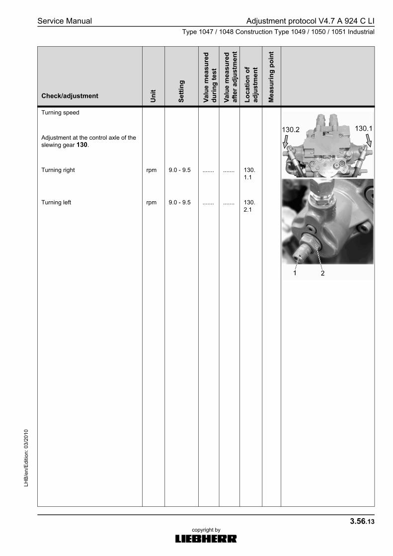
Turning speed
Adjustment at the control axle of the slewing gear 130.
Turning right rpm 9.0 - 9.5 ....... ....... 130.1.1
Turning left rpm 9.0 - 9.5 ....... ....... 130.2.1
Check/adjustment Uni
t
Setti
ng
Valu
e m
easu
red
durin
g te
st
Valu
e m
easu
red
afte
r adj
ustm
ent
Loca
tion
of
adju
stm
ent
Mea
surin
g po
int

Adjustment protocol V4.7 A 924 C LI Service ManualType 1047 / 1048 Construction Type 1049 / 1050 / 1051 Industrial
LHB
/en/
Edi
tion:
03/
2010
3.56.14copyright by
MJFCIFSS
Travel function
Travel motor regulationAdjusting screw 64on the travel motor 170.Screw in the measuring connection M2.
Begin of regulation bar 240 ....... ....... 64 45M2
End of regulation bar 320 ....... ....... 64 45M2
Check/adjustment Uni
t
Setti
ng
Valu
e m
easu
red
durin
g te
st
Valu
e m
easu
red
afte
r adj
ustm
ent
Loca
tion
of
adju
stm
ent
Mea
surin
g po
int

Service ManualType 1047 / 1048 Construction Type 1049 / 1050 / 1051 Industrial
3.56.15
Adjustment protocol V4.7 A 924 C LILH
B/e
n/E
ditio
n: 0
3/20
10
copyright by
MJFCIFSS
Output speed(travel speed)
Speed of universal joint shaftmeasured at the universal joint shaft in on-road gear forward / reverse
Tyre size 11.00-20: (20 km/h)
Standard machine forward rpm 1850 ±25 ....... ....... 160.1.1
Standard machine reverse rpm 1850 ±25 ....... ....... 160.2.1
Type 1050/1051 with Kessler axles
Standard machine forward rpm 2170 ±25 ....... ....... 160.1.1
Standard machine reverse rpm 2170 ±25 ....... ....... 160.2.1
Tyre size 11.00-20: (25 km/h)
Speeder machine forward rpm 2320 ±25 ....... ....... 160.1.1
Speeder machine reverse rpm 2320 ±25 ....... ....... 160.2.1
Checking measurement Xat travel motorStop screw (Qmin)
Standard machine mm 21.0 ....... ....... 35 35
Speeder machine mm 25.0 ....... ....... 35 35
Check/adjustment Uni
t
Setti
ng
Valu
e m
easu
red
durin
g te
st
Valu
e m
easu
red
afte
r adj
ustm
ent
Loca
tion
of
adju
stm
ent
Mea
surin
g po
int
Adjustment protocol V4.7 A 924 C LI Service ManualType 1047 / 1048 Construction Type 1049 / 1050 / 1051 Industrial
LHB
/en/
Edi
tion:
03/
2010
3.56.16copyright by
MJFCIFSS
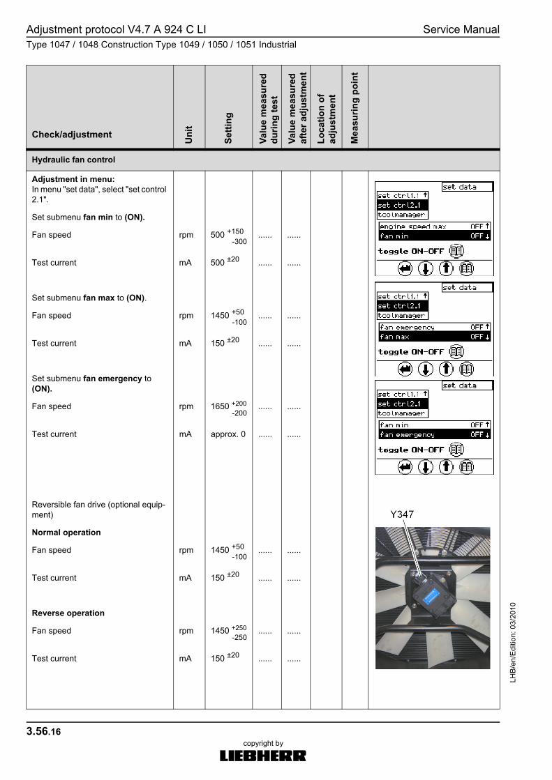
Hydraulic fan control
Adjustment in menu:In menu "set data", select "set control 2.1".
Set submenu fan min to (ON).
Fan speed rpm 500 +150
-300...... ......
Test current mA 500 ±20 ...... ......
Set submenu fan max to (ON).
Fan speed rpm 1450 +50
-100...... ......
Test current mA 150 ±20 ...... ......
Set submenu fan emergency to (ON).
Fan speed rpm 1650 +200
-200...... ......
Test current mA approx. 0 ...... ......
Reversible fan drive (optional equip-ment)
Normal operation
Fan speed rpm 1450 +50
-100...... ......
Test current mA 150 ±20 ...... ......
Reverse operation
Fan speed rpm 1450 +250
-250...... ......
Test current mA 150 ±20 ...... ......
Check/adjustment Uni
t
Setti
ng
Valu
e m
easu
red
durin
g te
st
Valu
e m
easu
red
afte
r adj
ustm
ent
Loca
tion
of
adju
stm
ent
Mea
surin
g po
int
Service ManualType 1047 / 1048 Construction Type 1049 / 1050 / 1051 Industrial
3.56.17
Adjustment protocol V4.7 A 924 C LILH
B/e
n/E
ditio
n: 0
3/20
10
copyright by
MJFCIFSS
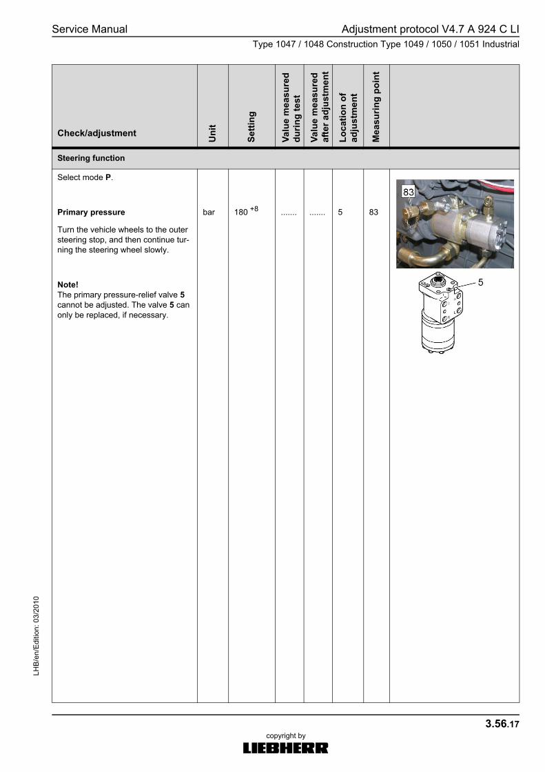
Steering function
Select mode P.
Primary pressure bar 180 +8 ....... ....... 5 83
Turn the vehicle wheels to the outer steering stop, and then continue tur-ning the steering wheel slowly.
Note!The primary pressure-relief valve 5 cannot be adjusted. The valve 5 can only be replaced, if necessary.
Check/adjustment Uni
t
Setti
ng
Valu
e m
easu
red
durin
g te
st
Valu
e m
easu
red
afte
r adj
ustm
ent
Loca
tion
of
adju
stm
ent
Mea
surin
g po
int
Adjustment protocol V4.7 A 924 C LI Service ManualType 1047 / 1048 Construction Type 1049 / 1050 / 1051 Industrial
LHB
/en/
Edi
tion:
03/
2010
3.56.18copyright by
MJFCIFSS
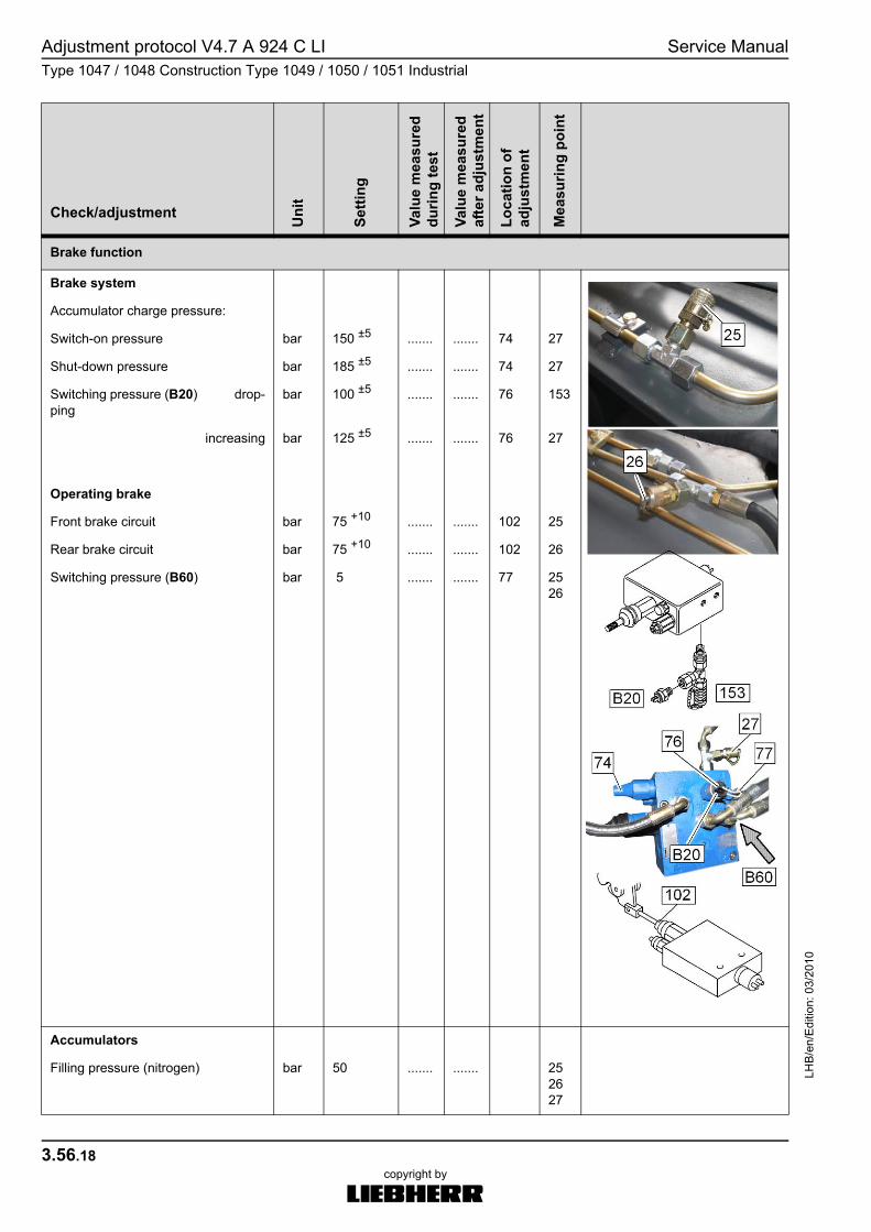
Brake function
Brake system
Accumulator charge pressure:
Switch-on pressure bar 150 ±5 ....... ....... 74 27
Shut-down pressure bar 185 ±5 ....... ....... 74 27
Switching pressure (B20) drop-ping
bar 100 ±5 ....... ....... 76 153
increasing bar 125 ±5 ....... ....... 76 27
Operating brake
Front brake circuit bar 75 +10 ....... ....... 102 25
Rear brake circuit bar 75 +10 ....... ....... 102 26
Switching pressure (B60) bar 5 ....... ....... 77 2526
Accumulators
Filling pressure (nitrogen) bar 50 ....... ....... 252627
Check/adjustment Uni
t
Setti
ng
Valu
e m
easu
red
durin
g te
st
Valu
e m
easu
red
afte
r adj
ustm
ent
Loca
tion
of
adju
stm
ent
Mea
surin
g po
int