Two Stage Seeded Soft X-Ray Free-Electron Laser · 2 . NATURE PHOTONICS | . SUPPLEMENTARY...
16
SUPPLEMENTARY INFORMATION DOI: 10.1038/NPHOTON.2013.277 NATURE PHOTONICS | www.nature.com/naturephotonics 1 Supplementary Materials for Two Stage Seeded Soft X-Ray Free-Electron Laser E. Allaria 1 , D. Castronovo 1 , P. Cinquegrana 1 , P. Craievich 1,2 , M. Dal Forno 1,3 , M. B. Danailov 1 , G. D’Auria 1 , A. Demidovitch 1 , G. De Ninno 1,4 , S. Di Mitri 1 , B. Diviacco 1 , W. M. Fawley 1 , M. Ferianis 1 , E. Ferrari 1,3 , L. Froehlich 1 , G. Gaio 1 , D. Gauthier 4 , L. Giannessi 1,5 , R. Ivanov 1 , B. Mahieu 1,6 , N. Mahne 1 , I. Nikolov 1 , F. Parmigiani 1,3 , G. Penco 1 , L. Raimondi 1 , C. Scafuri 1 , C. Serpico 1 , P. Sigalotti 1 , S. Spampinati 1,4 , C. Spezzani 1 , M. Svandrlik 1 , C. Svetina 1,3 , M. Trovò 1 , M. Veronese 1 , D. Zangrando 1 , M. Zangrando 1,7 1 Elettra-Sincrotrone Trieste, Trieste, ITALY 2 now at Paul Scherrer Institute, Villigen PSI, 5232, SWITZERLAND 3 University of Trieste, Trieste, ITALY 4 Nova Gorica University, Nova Gorica, SLOVENIA 5 ENEA C.R. Frascati, Frascati, ITALY 6 SPAM, CEA Saclay, France 7 IOM-CNR, Laboratorio TASC, Trieste, ITALY correspondence to: [email protected] or [email protected] This PDF file includes: Supplementary Text Figs. S1 to S5 Table S1 to S2 Supplementary Text References (S1–S18) © 2013 Macmillan Publishers Limited. All rights reserved.
Transcript of Two Stage Seeded Soft X-Ray Free-Electron Laser · 2 . NATURE PHOTONICS | . SUPPLEMENTARY...
SUPPLEMENTARY INFORMATIONDOI: 10.1038/NPHOTON.2013.277
NATURE PHOTONICS | www.nature.com/naturephotonics 1
1
Supplementary Materials for
Two Stage Seeded Soft X-Ray Free-Electron Laser
E. Allaria1, D. Castronovo1, P. Cinquegrana1, P. Craievich1,2, M. Dal Forno1,3, M. B.
Danailov1, G. D’Auria1, A. Demidovitch1, G. De Ninno1,4, S. Di Mitri1, B. Diviacco1, W. M. Fawley1, M. Ferianis1, E. Ferrari1,3, L. Froehlich1, G. Gaio1, D. Gauthier4, L.
Giannessi1,5, R. Ivanov1, B. Mahieu1,6, N. Mahne1, I. Nikolov1, F. Parmigiani1,3, G. Penco1, L. Raimondi1, C. Scafuri1, C. Serpico1, P. Sigalotti1, S. Spampinati1,4, C.
Spezzani1, M. Svandrlik1, C. Svetina1,3, M. Trovò1, M. Veronese1, D. Zangrando1, M. Zangrando1,7
1Elettra-Sincrotrone Trieste, Trieste, ITALY 2 now at Paul Scherrer Institute, Villigen PSI, 5232, SWITZERLAND 3University of Trieste, Trieste, ITALY 4Nova Gorica University, Nova Gorica, SLOVENIA 5ENEA C.R. Frascati, Frascati, ITALY 6SPAM, CEA Saclay, France 7IOM-CNR, Laboratorio TASC, Trieste, ITALY
correspondence to: [email protected] or [email protected]
This PDF file includes:
Supplementary Text Figs. S1 to S5 Table S1 to S2 Supplementary Text References (S1–S18)
© 2013 Macmillan Publishers Limited. All rights reserved.
2 NATURE PHOTONICS | www.nature.com/naturephotonics
SUPPLEMENTARY INFORMATION DOI: 10.1038/NPHOTON.2013.277
2
Supplementary Text
The Linear Accelerator
The FERMI FEL is driven by a normal-conducting, S-band (3 GHz) linac presently capable of accelerating electron bunches up to 1.2 GeV final energy at a 10-Hz repetition rate [S1-S3]. The beam originates in a photoinjector which provides 500 pC, 2.8 ps long (rms) bunches that, following acceleration to ~100-MeV energy, pass through a so-called “laser heater” region. Here a combination of an external laser plus a short undulator situated in the middle of a chicane increase the electrons' incoherent energy spread in order to control longitudinal microbunching instabilities [S4, S5]. As previously found by the LCLS team, just a small amount of heating (~10 keV) is necessary [S6, S7]. Following additional acceleration to 300 MeV, the electron bunch is then longitudinally compressed to ~300 Amp current by the first magnetic chicane (BC1); the experiments reported here did not use a second bunch compressor that is present at the 650-MeV energy point.
The longitudinal uniformity of the electron parameters at the end of the linac, such
as the current, energy, and both longitudinal and transverse emittances, is a prerequisite of great importance in a seeded FEL that seeks high longitudinal coherence because the electron beam is the medium by which the coherence properties of the seed are encoded into the final FEL output radiation. Any distortion in this encoding process will propagate downstream from the first modulator and can temporally modulate the phase and amplitude of the final FEL output. Such modulations can both reduce the output radiation energy and degrade the spectrum. For this reason, electron beam preparation in the case of a seeded FEL, and, in particular, for a double stage, harmonic upshift FEL operating with the fresh bunch technique, differs substantially from that which is required for a shot-noise-initiated SASE source, whose output coherence length is intrinsically limited.
In order to ensure a relatively flat current and energy distribution along the electron
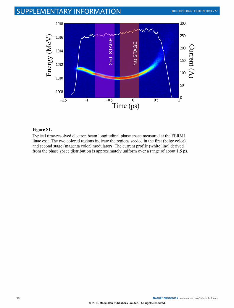
bunch, a fourth-harmonic RF cavity installed just before BC1 linearizes the electron beam's longitudinal phase space [S8]. The system is based on a XL5 klystron built by SLAC and operating at the European frequency of 11.992 GHz. The required accelerating voltage is about 20 MV/m, equivalent to about 20 MW of RF power at the cavity input. As seen by the electron beam bunches, this cavity is operated close to the maximum decelerating phase. However, at higher compression values (and thus higher currents), longitudinal wake fields in the accelerating cavities downstream of BC1 can seriously degrade the electron beam's energy distribution by introducing nonlinearities in the longitudinal phase space. To measure the efficacy of our control (i.e., via tuning the phase and amplitude of both the X-band and downstream accelerating cavities) of these wake fields, we use a high energy, dipole deflecting cavity (HERFD) at the linac end together with a spectrometer to characterize the longitudinal phase space before entrance to the spreader and undulator lines [S9, S10]. Figure S1 shows a typical measurement at a diagnostic screen following the HERFD that indicates most of the beam charge is contained within a 1.5-ps core with ~280 A current. There is a residual (and undesired)
© 2013 Macmillan Publishers Limited. All rights reserved.
NATURE PHOTONICS | www.nature.com/naturephotonics 3
SUPPLEMENTARY INFORMATIONDOI: 10.1038/NPHOTON.2013.277
3
quadratic chirp on the beam energy; such a chirp in combination with the R56 of each stage’s dispersion section can produce a linear chirp on the output FEL radiation. Following the linac, the electron beam is bent horizontally into a dogleg-geometry spreader and then, depending upon the spreader's dipole magnet settings, is bent back again into one of the two undulator lines. The optics of the spreader's magnetic lattice are designed to minimize the coherent synchrotron radiation (CSR)-induced energy spread and transverse emittance growth, which otherwise would dilute the beam's six-dimensional brightness and thus reduce the FEL gain. The additional energy spread is kept small by a short, multiple dipole scheme that makes the spreader optics achromatic while the net emittance growth is nearly fully eliminated by a “balanced” optics configuration [S10].
Integrated feedback systems monitor and keep constant the electron beam charge, energy, compression and trajectory at different positions along the linac. These feedback systems are important to control temporal drifts in various components (e.g., klystron phases) and were crucial to ensure stable, optimal FEL operations.
Seed Laser
The seed laser system used for the fresh-bunch FEL-2 experiments reported here is the same as previously used for those on FEL-1 [30, S11]. It is based on a Ti:Sapphire regenerative amplifier-single pass amplifier combination, where the required UV seed pulses are obtained by pumping a tunable optical parametric amplifier with consequent harmonic conversion to UV, or , in the case of fixed wavelength operation mode, by third harmonic generation of 261 nm pulses in BBO crystals. In order to provide a larger margin in terms of available seed power, the fixed wavelength option has been used. In this configuration, UV pulses of up to 100 µJ pulse energy and 180 fs pulse duration (FWHM) can be delivered to the modulator undulator with a spot size of about 1.5 mm diameter (defined as the 1/e2 intensity level). The pulse energy could be remotely varied down to 1 µJ while the transverse spot position could be kept constant at a virtual image of the undulator center on a CCD camera by a piezo tip-tilt based position feedback. The mutual temporal synchronization of the seed laser pulses and the electron bunch is of crucial importance for the fresh bunch scheme. For this reason, a significant effort has been made to keep timing jitter and drifts as low as possible. The laser oscillator of the seed laser has been locked to the low phase noise timing reference pulses delivered through a stabilized fiber link by a balanced optical cross-correlator developed at Elettra. Using a purely optical locking of the laser, a timing jitter of less than 50 fs RMS has been consistently obtained. A single shot cross-correlator and piezo-translation delay stage based feedback allows compensation for slow timing drifts (typically a few hundred femtoseconds over hours) arising in the optical amplifier section.
Undulator System All undulators in FERMI employ iron-free, pure permanent magnet technology. The
first stage modulator, in which the electron beam directly interacts with the optical field of the seed laser, has a standard Halbach magnetic configuration [S12] with fixed linear polarization. To maintain the resonance condition when changing either the electron
© 2013 Macmillan Publishers Limited. All rights reserved.
4 NATURE PHOTONICS | www.nature.com/naturephotonics
SUPPLEMENTARY INFORMATION DOI: 10.1038/NPHOTON.2013.277
4
energy or the seed wavelength, the modulator’s magnetic field strength is adjustable through a motorized magnetic gap drive system.
The other undulators (i.e., all the radiators of both stages and the second stage modulator) use an APPLE-II design [37] featuring variable elliptical polarization, including horizontal, vertical and right/left handed circular modes. Here also, the resonant wavelength can be tuned by changing the magnetic gap.
Table S1 lists the main parameters of the undulators: period length λ0, number of segments NS, number of periods per segment NP, maximum deflection parameter in horizontal (KH
MAX), vertical (KVMAX) and circular (KC
MAX) polarization.
Radiation diagnostics system
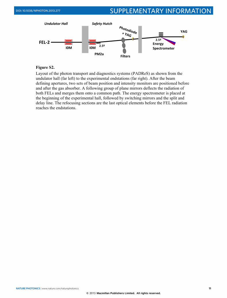
Online diagnostics for measuring the shot-to-shot radiation pulse energy and spectra are integrated within the FERMI FEL Photon Analysis Delivery and Reduction System (PADReS) [S13, S14]. A layout of the various diagnostic components is shown in Fig. S2. There are two intensity monitors (I0 monitors) that are based on photoionization of a rare gas (Nitrogen) at low particle density in the range of 1011 cm-3 (p ≈ 10-5 mbar). The monitors are almost completely transparent to the radiation due to the low pressure in the vacuum chambers. They are usable on the whole wavelength range covered by FERMI@Elettra, have a wide dynamical range, and, in general, do not suffer either from saturation effects nor from fluctuations in the transverse photon beam position. Being free from degradation and destruction, they can be used continuously for shot-to-shot intensity measurements.
As the Nitrogen absorption cross section presents substantial variations depending on the ionizing radiation wavelength [S15], so does the signal generated in the I0 monitors; in particular, they are strongly more sensitive to the longer wavelengths emitted by the first stage of FEL-2. In this way, provided that the proper calibration is carried out, it is possible to derive the absolute number of photons per FEL pulse emitted by the first stage on a shot-to-shot basis.
In order to measure the relative intensities of the contributions coming from the two
FEL-2 stages, thin (thickness = 300 nm) Zr and Pd filters are installed in the PADReS safety hutch. They serve as wavelength bandpass filters: the Zr filter has a ~20%-transmission in the 6.2-12.4 nm range, while the Pd filter has about 8% transmission in the 3.5-10 nm range. At longer wavelengths (>30 nm), both filters have transmission levels well below 0.1%, ruling out possible contamination from first-stage photons. The filters are placed in front of a calibrated-photodiode system that determines the intensity of the FEL emission from the second stage. For the FEL-2 results reported here, the first-stage photon numbers per pulse were determined by the I0 monitors.
PADRes also has an online energy spectrometer that can acquire FEL spectra over a
wavelength range of 3 to 100 nm [S16]. It uses 3 identical Si substrates with optical surfaces of 250x20 mm2; two of them have the central 60x17 mm2-area grooved (e.g., a diffraction grating is ruled in their central part), while the third is a pure plane mirror. The two gratings, planar in shape, have a variable line spacing (VLS) ruling so they can both
© 2013 Macmillan Publishers Limited. All rights reserved.
NATURE PHOTONICS | www.nature.com/naturephotonics 5
SUPPLEMENTARY INFORMATIONDOI: 10.1038/NPHOTON.2013.277
5
diffract and focus the radiation. Only a small fraction of the beam is diffracted and focused into the spectrometer detector, while most of the beam (~97% of the intensity) goes unperturbed in the 0-order of the grating to the downstream user beamlines. The diffracted radiation is focused onto a Ce:YAG crystal positioned in vacuum on a viewport that is then imaged by a CCD detector positioned outside the instrument. The horizontal position of the focused radiation (e.g., in the diffraction plane of the gratings) on the CCD is a function of the FEL radiation wavelength, and the resultant spectral information is stored on a shot-by-shot basis. The vertical direction on the CCD, on the other hand, represents the projected transverse distribution of the radiation pulse.
Discussion of Fresh Bunch Physics and Experimental Considerations
As mentioned above in the main body of the paper, the concept of using a harmonic
upshift method to transfer the coherence and temporal properties of an external, long wavelength, seed laser pulse to a much shorter wavelength FEL output pulse was proposed by many authors over the past couple decades. Nearly all these concepts rely upon the coherent bunching and associated higher harmonics produced on the electron beam during its interaction with the seed laser in the combination of an undulator (the “modulator”) immediately followed by a chromatic dispersion section that converts the energy modulation into density bunching. Here we explain some additional considerations that apply for such modulator-radiator upshift schemes and the various observations that show we indeed have a true “fresh bunch” mode for the second stage, short wavelength radiation.
In order to get strong bunching and subsequent FEL emission at harmonic h, it
generally is necessary to produce an energy modulation ΔE ≥ hσE. In a one-stage HGHG configuration, so long as ΔE ≤ 0.5 ρEB , where EB is the electron beam energy and ρ is the so-called FEL parameter [12], the FEL gain in the following “radiator” undulators is not strongly reduced by the induced energy spread and the output radiation power can reach saturation levels comparable to ρIBEB where IB is the electron beam current. Thus, in contrast to SASE FEL configurations such as LCLS in which the effective criterion for permissible incoherent energy spread is σE ≤ 0.5 ρEB, for an harmonic upshift FEL the proper criterion is σE ≤ (0.5/h) ρEB if comparable output power is sought. Consequently, because σE tends to scale directly with IB due to the underlying physics of bunch compression, the conflicting needs of a low σE together with a moderately high IB (needed for a reasonably low exponential gain length and high saturation power) tend to rule out reaching the carbon K-edge at 4.2 nm wavelength in a single harmonic upshift stage if beginning with λseed ≥ 200 nm.
In a multistage harmonic upshift FEL such as FERMI’s FEL-2, the shorter radiation
wavelength corresponding to each successive stage will almost certainly have a smaller FEL parameter ρ than the preceding stage. Growth of σE in each stage can then strongly reduce gain in following stages, especially in the last stage. In the so-called “whole bunch” approach, the entire electron beam pulse takes part in the FEL interaction in each and every stage (presuming that the first stage was seeded by a sufficiently long duration
© 2013 Macmillan Publishers Limited. All rights reserved.
6 NATURE PHOTONICS | www.nature.com/naturephotonics
SUPPLEMENTARY INFORMATION DOI: 10.1038/NPHOTON.2013.277
6
laser pulse) and both the power level and corresponding increase in σE must be carefully limited in each stage up to the last radiator [33].
When the seed is shorter than the electron bunch, toward the head side of the seed
there exists a region where “fresh” electrons, i.e., not energy modulated by the seed, can be reached by the radiation “slipping” forward. It has been previously shown that in this region the cascade can produce quite high peak power in the form of ultrashort pulses, but these pulses preserve neither the temporal nor spectral properties of the exernal seed, resulting in a substantial degradation of the longitudinal coherence [40]
Experimentally, whole bunch, two stage cascades have been studied at FERMI
[S17] with net harmonic upshift values as large as 65 but the output pulse energies are typically smaller than a few microjoules in the 10-nm region, significantly smaller than we have obtained using the fresh bunch mode of operation.
It is this σE limitation issue together with the goal of accessing the carbon K-edge at 4.2 nm that led to the decision at Sincrotrone Trieste to base the design of FERMI’s FEL-2 on the “fresh bunch” idea of Ben-Zvi et al.
The energy growth versus longitudinal position along the undulator (see the inset in
Fig. 1) provides important information concerning the power e-folding length (i.e., the gain length Lg), relevant to our operating conditions. A best fit of the observed exponential growth, calculated by excluding the breaks between the separate radiator sections, provides Lg=2.5±0.4 m. This is in good accord with the gain length of 2.6 m estimated using the standard Xie formalism [S18] from the machine operating parameters (see Table S2) at 10.8 nm. This result confirms that the second stage is run in a true Yu [24] high gain harmonic generation mode and that the emission is not coherent spontaneous emission from a prebunched beam with little to no gain
To establish that the short wavelength output emission at λ2 truly originated both in
the second stage and via an HGHG, fresh bunch process, we made a series of specific measurements and observations:
1) in normal operation of the first stage with the seed laser on, there was essentially only very weak spontaneous emission at the second stage wavelength λ2 if any of the following conditions applied: the gaps of the second stage radiator undulators are fully open (i.e., K ≈ 0) or are set to a non-integer harmonic resonance with λseed, the second dispersion section strength is set to near zero, or if the delay line chicane strength is very weak. All these conditions indicate that the normal narrow bandwidth emission at λ2 must come from the second stage. 2) There is no spontaneous (or SASE) emission detectable in the spectrometer at λ2 if the seed laser shutter is closed, indicating that the seeding process in the first stage is a necessary element for the short wavelength emission. 3) The sensitivity of the second stage output both to the relative temporal synchronization of the external laser and to the strength of the delay line (DL)
© 2013 Macmillan Publishers Limited. All rights reserved.
NATURE PHOTONICS | www.nature.com/naturephotonics 7
SUPPLEMENTARY INFORMATIONDOI: 10.1038/NPHOTON.2013.277
7
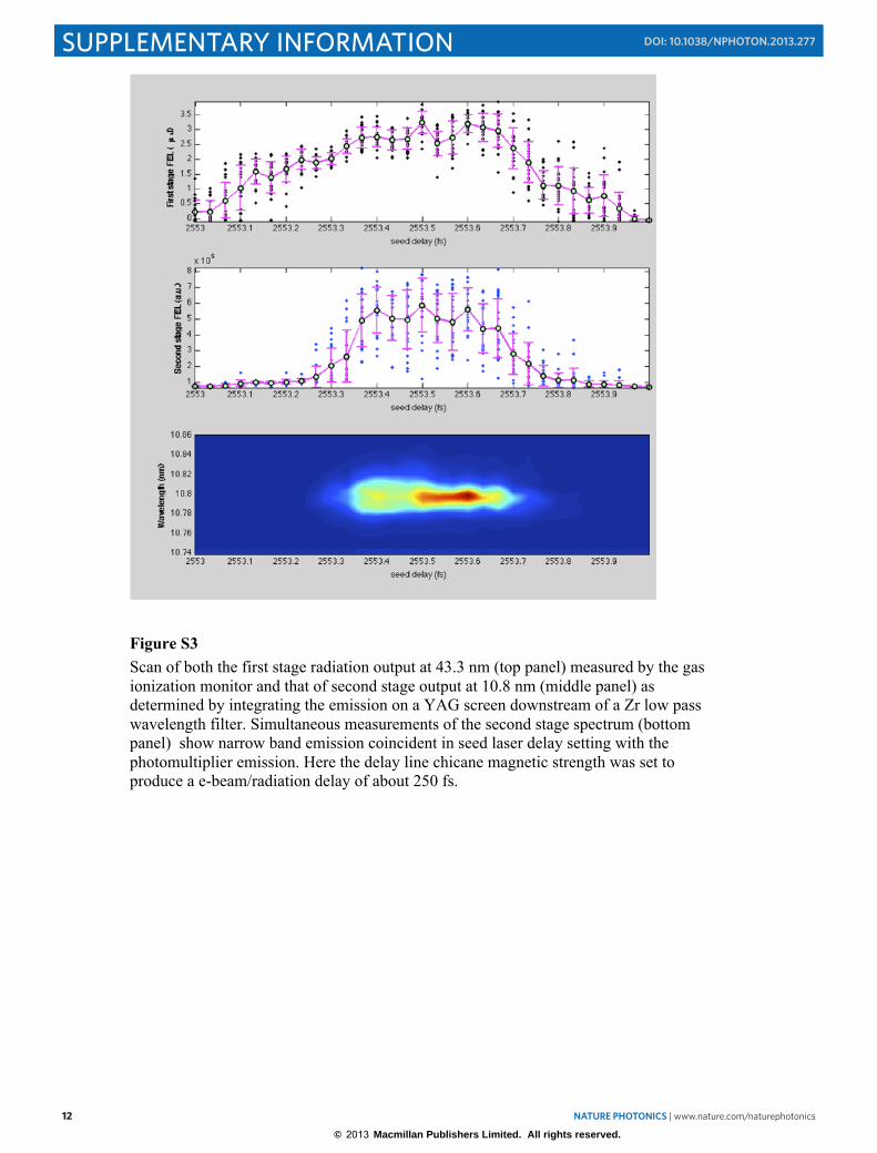
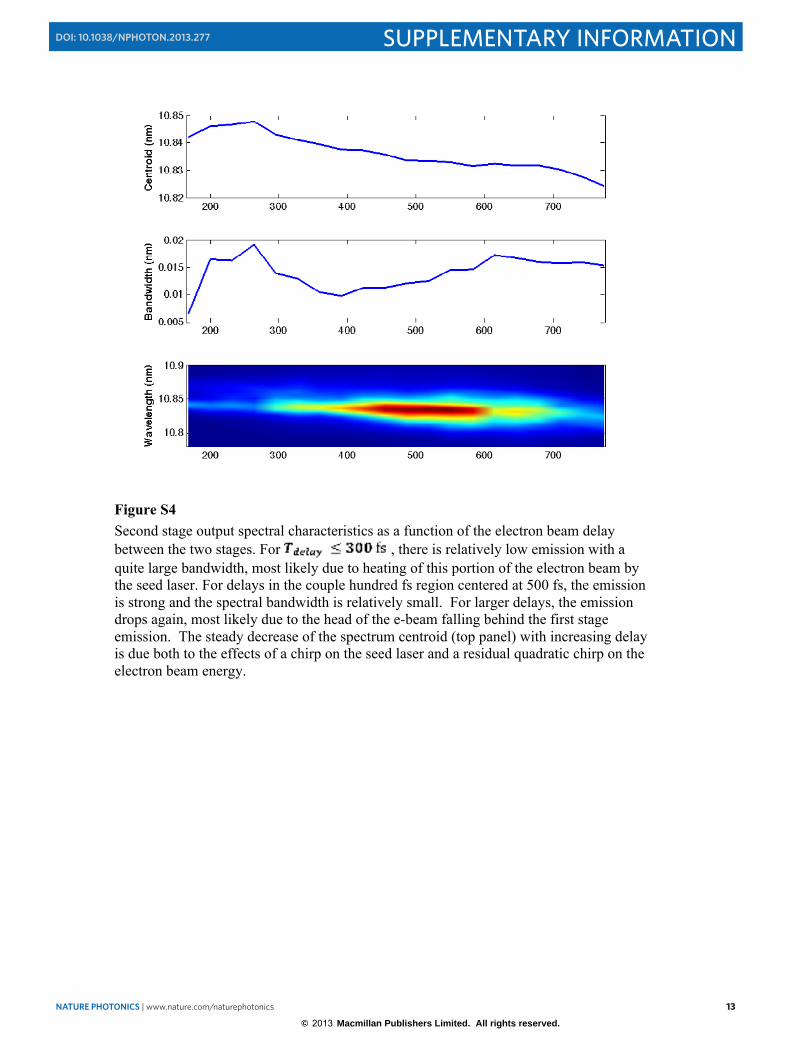
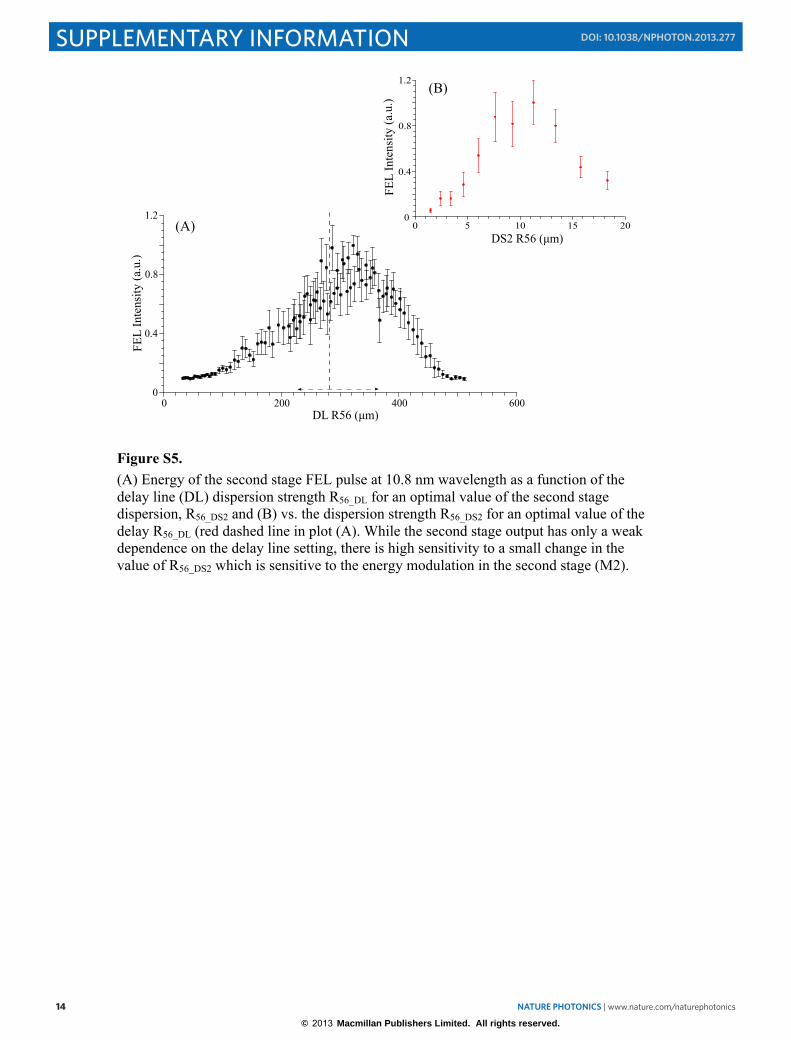
provides the additional proof that the emission at λ2 is due to a fresh bunch interaction mode. Figure S3 displays the simultaneous measurements of the first stage emission at λ1, the second stage emission at λ2, and the spectrum centered at λ2 as a function of seed laser timing. The second stage output occupies a much narrower window in seed delay timing than that of the first stage output. When the seed timing for this particular example is less than 2553.3 fs, the seed laser modulates the head portions of the electron beam and there is vanishingly small second stage emission, in accord with the supposition that the delay line section has effectively retarded the entrance of the electron beam to the second stage too greatly for there to be interaction with the first stage radiation output. As the seed laser timing is increased so as to overlay the main body of the electron beam (i.e., 2553.3fs ≤ Tseed ≤ 2553.7 fs), there is both strong first and second stage emission. As the seed laser is delayed even further toward the electron beam tail, the drop in current there reduces the first stage emission; this consequently strongly inhibits the second stage emission. We note that the second stage emission is also much more sensitive to the temporally local mean electron energy than is the first stage. Thus for the usual circumstance for FERMI of a couple MeV variation in energy along the electron beam pulse, the exact temporal dependence of the second stage output will be a function of the radiator strength K. 4) Figure S4 shows the behavior of the FEL output spectrum versus the delay line strength. In the lower plot the spectra at each delay line position are normalized to allow a comparison of the spectral shape at different delays. When the delay is substantially larger than the seed pulse duration (FWHM ~ 170 fs) the first and second stage are operating on independent regions of the electron bunch and the second stage radiation has a narrower spectrum and somewhat larger pulse energy. For smaller delays, the delay is comparable to the seed pulse length and the second stage radiation may partially originate from electrons that were previously heated by interaction with the external seed laser in the first stage. In this case we observe a drop in the intensity and a significant broadening of the spectrum. If the DL strength is set close to zero, the emission at the first stage wavelength, λ1 , can increase by more than a factor of two because the second stage modulator is then acting as if it were the third radiator of the first stage. However, the emission at λ2 is quite weak to non-existent. 5) Figure S5 (A) shows the second stage output energy corresponding to the data shown in the previous figure. In Figure S5 (B), a scan of the FEL output energy at λ2 versus the second stage dispersion section strength (R56_DS2) displays the high sensitivity of the FEL output to a small change in this parameter. For this data, the delay line strength is equivalent to a dispersion strength of R56_DL= 280µm. One sees that both the FWHM of the curve of EFEL (R56_DS2) and the occurrence of the local maximum at a value ~10 µm is so small when compared to the delay line strength that this behavior can only be associated with some physical process occurring after the delay chicane, i.e., maximizing the microbunching associated with the energy modulation produced in the second stage modulator M2 by the first stage FEL radiation.
© 2013 Macmillan Publishers Limited. All rights reserved.
8 NATURE PHOTONICS | www.nature.com/naturephotonics
SUPPLEMENTARY INFORMATION DOI: 10.1038/NPHOTON.2013.277
8
In summary, we believe the above observations show that the short wavelength emission both originates in the second stage radiator and comes from a “fresh bunch” portion of the electron beam that was unperturbed by the external seed laser in the first modulator.
© 2013 Macmillan Publishers Limited. All rights reserved.
NATURE PHOTONICS | www.nature.com/naturephotonics 9
SUPPLEMENTARY INFORMATIONDOI: 10.1038/NPHOTON.2013.277
9
REFERENCES S1 S. Di Mitri et al., Nucl. Instrum. and Meth. A, 608, 19 (2009). S2 G. Penco et al., “Optimization of a high brightness photoinjector for a seeded FEL
facility", J. of Instrumentation 8, 05015 (2013). S3 G. D’Auria et al., Proc. PAC07, Paper TUPMN029, Albuquerque, USA (2007). S4 Z. Huang et al., Phys. Rev. ST Accel. Beams 7, 074401 (2004). S5 E. Saldin, E. A. Schneidmiller and M. V. Yurkov, Nucl. Instrum. Meth. 528, 355
(2004) S6 Z. Huang et al., Phys. Rev. STAB 13, 020703 (2010). S7 S. Spampinati et al., Proc. 2012 FEL Conf., Paper MOPD58, Nara, Japan (2012). S8 G. D’Auria et al., The X-Band system for the FERMI@Elettra FEL Project, Proc.
IPAC 2010, Paper TUPE015, Kyoto, Japan (2010), S9 P. Craievich et al., Proc. DIPAC 2007 , Paper TUPC10, Venice, Italy (2007) and
G. Penco et al., Proc. 2012 FEL Conf., Paper WEPD20, Nara, Japan (2012) S10 S. Di Mitri, M. Cornacchia, and S. Spampinati, Phys. Rev. Lett. 110, 014801
(2013) S11 E.Allaria et al., New Journal of Physics 14, 113009 (2012) S12 K. Halbach, Nucl. Instrum. Meth. 187, 109 (1981). Also available at
http://www.askmar.com/Magnets/Physical and Optical Properties.pdf S13 M. Zangrando et al., Proc. SPIE 8504, 850404 (2012) S14 M. Zangrando et al., Rev. Sci. Instrum. 80, 113110, 305 (2009). S15 W.F. Chan, G. Cooper, R.N.S. Sodhi, and C.E. Brion, Chemical Physics 170, 81
(1993). S16 C. Svetina et al., Proc. SPIE 8139, 81390J (2011). S17 L. Giannessi et al., Proc. 2012 FEL Conf., Paper MOOB06, Nara, Japan (2012). S18 M. Xie, Nucl. Instrum. Methods A 445, 59 (2000).
© 2013 Macmillan Publishers Limited. All rights reserved.
10 NATURE PHOTONICS | www.nature.com/naturephotonics
SUPPLEMENTARY INFORMATION DOI: 10.1038/NPHOTON.2013.277
10
Figure S1. Typical time-resolved electron beam longitudinal phase space measured at the FERMI linac exit. The two colored regions indicate the regions seeded in the first (beige color) and second stage (magenta color) modulators. The current profile (white line) derived from the phase space distribution is approximately uniform over a range of about 1.5 ps.
© 2013 Macmillan Publishers Limited. All rights reserved.
NATURE PHOTONICS | www.nature.com/naturephotonics 11
SUPPLEMENTARY INFORMATIONDOI: 10.1038/NPHOTON.2013.277
11
!"#$%&'( &'( %)*+
%)*+",-./0123-45.67-5-.
89656:;6:-1<1=>?
8(%@
!"#$%&'()%*+,-.)/"%01'("//
!;A5-.B
=>?
Figure S2. Layout of the photon transport and diagnostics systems (PADReS) as shown from the undulator hall (far left) to the experimental endstations (far right). After the beam defining apertures, two sets of beam position and intensity monitors are positioned before and after the gas absorber. A following group of plane mirrors deflects the radiation of both FELs and merges them onto a common path. The energy spectrometer is placed at the beginning of the experimental hall, followed by switching mirrors and the split and delay line. The refocusing sections are the last optical elements before the FEL radiation reaches the endstations.
© 2013 Macmillan Publishers Limited. All rights reserved.
12 NATURE PHOTONICS | www.nature.com/naturephotonics
SUPPLEMENTARY INFORMATION DOI: 10.1038/NPHOTON.2013.277
12
Figure S3 Scan of both the first stage radiation output at 43.3 nm (top panel) measured by the gas ionization monitor and that of second stage output at 10.8 nm (middle panel) as determined by integrating the emission on a YAG screen downstream of a Zr low pass wavelength filter. Simultaneous measurements of the second stage spectrum (bottom panel) show narrow band emission coincident in seed laser delay setting with the photomultiplier emission. Here the delay line chicane magnetic strength was set to produce a e-beam/radiation delay of about 250 fs.
© 2013 Macmillan Publishers Limited. All rights reserved.
NATURE PHOTONICS | www.nature.com/naturephotonics 13
SUPPLEMENTARY INFORMATIONDOI: 10.1038/NPHOTON.2013.277
13
Figure S4 Second stage output spectral characteristics as a function of the electron beam delay between the two stages. For , there is relatively low emission with a quite large bandwidth, most likely due to heating of this portion of the electron beam by the seed laser. For delays in the couple hundred fs region centered at 500 fs, the emission is strong and the spectral bandwidth is relatively small. For larger delays, the emission drops again, most likely due to the head of the e-beam falling behind the first stage emission. The steady decrease of the spectrum centroid (top panel) with increasing delay is due both to the effects of a chirp on the seed laser and a residual quadratic chirp on the electron beam energy.
© 2013 Macmillan Publishers Limited. All rights reserved.
14 NATURE PHOTONICS | www.nature.com/naturephotonics
SUPPLEMENTARY INFORMATION DOI: 10.1038/NPHOTON.2013.277
14
Figure S5. (A) Energy of the second stage FEL pulse at 10.8 nm wavelength as a function of the delay line (DL) dispersion strength R56_DL for an optimal value of the second stage dispersion, R56_DS2 and (B) vs. the dispersion strength R56_DS2 for an optimal value of the delay R56_DL (red dashed line in plot (A). While the second stage output has only a weak dependence on the delay line setting, there is high sensitivity to a small change in the value of R56_DS2 which is sensitive to the energy modulation in the second stage (M2).
© 2013 Macmillan Publishers Limited. All rights reserved.
NATURE PHOTONICS | www.nature.com/naturephotonics 15
SUPPLEMENTARY INFORMATIONDOI: 10.1038/NPHOTON.2013.277
15
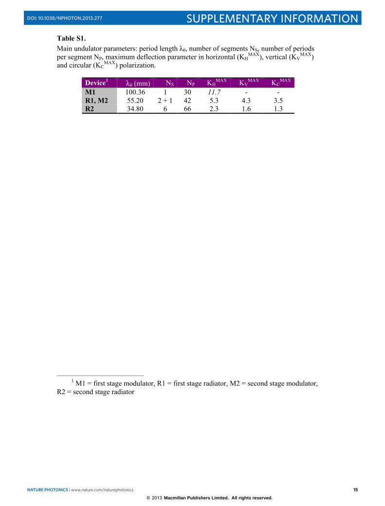
Table S1. Main undulator parameters: period length λ0, number of segments NS, number of periods per segment NP, maximum deflection parameter in horizontal (KH
MAX), vertical (KVMAX)
and circular (KCMAX) polarization.
Device1 λ0 (mm) NS NP KH
MAX KVMAX KC
MAX M1 100.36 1 30 11.7 - - R1, M2 55.20 2 + 1 42 5.3 4.3 3.5 R2 34.80 6 66 2.3 1.6 1.3
1 M1 = first stage modulator, R1 = first stage radiator, M2 = second stage modulator,
R2 = second stage radiator
© 2013 Macmillan Publishers Limited. All rights reserved.
16 NATURE PHOTONICS | www.nature.com/naturephotonics
SUPPLEMENTARY INFORMATION DOI: 10.1038/NPHOTON.2013.277
16
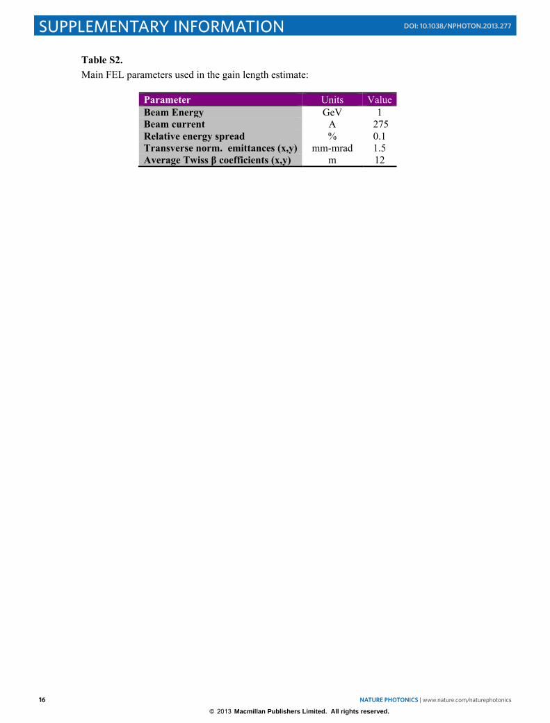
Table S2. Main FEL parameters used in the gain length estimate:
Parameter Units Value Beam Energy GeV 1 Beam current A 275 Relative energy spread % 0.1 Transverse norm. emittances (x,y) mm-mrad 1.5 Average Twiss β coefficients (x,y) m 12
© 2013 Macmillan Publishers Limited. All rights reserved.