TWO-DIMENSIONAL SEISMIC ANALYSIS OF MULTI-STORY …
10
TWO-DIMENSIONAL SEISMIC ANALYSIS OF MULTI-STORY LIGHT-FRAME WOOD BUILDINGS I. P. Christovasilis 1 and A. Filiatrault 2 ABSTRACT This paper presents the development and validation of a new two-dimensional (2D) numerical framework, suitable for nonlinear inelastic static and dynamic analysis of light-frame wood buildings that incorporate sheathed woodframe shear walls as a lateral-load-resisting system. The 2D building model is based on a sub- structuring approach that considers each floor diaphragm as a rigid body with three kinematic degrees-of-freedom (DOF). A sub-structure model is developed for each individual single-story wall assembly that interacts with the adjacent diaphragms and generates the resisting internal forces. The 2D shear wall model takes explicit consideration of all sheathing-to-framing connections with nonlinear inelastic phenomenological springs, while offers the capability to optionally simulate: (i) axial and bending deformations in the framing members; (ii) contact/separation phenomena between framing members and diaphragms; and (iii) anchoring equipment (i.e. anchor bolts, holdown devices) typically installed in light-frame shear walls to develop a vertical load path that resists overturning moments. Corotational descriptions are used to solve for displacement fields that satisfy the equilibrium equations in the deformed configuration, accounting for geometric nonlinearity and P-Δ effects. To validate the proposed numerical framework, a number of simulation examples are presented, based on experimental results from pseudo-static cyclic tests of single- and two-story full-scale shear wall specimens. These examples demonstrate the capability of the model to simulate accurate load paths in the structure and successfully predict variations in strength, stiffness and energy dissipation characteristics of the lateral-load-resisting system. Introduction The multi-component nature of light-frame wood structures and the versatility of the finite element method have led to the development of both simplified – sub-modeling – and detailed – sub-structuring – approaches to simulate the response of the structural components that assemble a light-frame wood shear wall or a complete light-frame wood building. The current state-of-practice of nonlinear analysis of this type of structures is represented by the 1 st generation numerical tools developed by Folz and Filiatrault (2001; 2004a; 2004b), as part of the CUREE-Caltech Woodframe Project. The shear wall model (Folz and Filiatrault 2001) is based 1 Graduate Research Assistant, Dept. of Civil, Structural and Environmental Engineering, University at Buffalo, State University of New York, Buffalo, NY 14260 2 Professor, Dept. of Civil, Structural and Environmental Engineering, University at Buffalo, State University of New York, Buffalo, NY 14260 Proceedings of the 9th U.S. National and 10th Canadian Conference on Earthquake Engineering Compte Rendu de la 9ième Conférence Nationale Américaine et 10ième Conférence Canadienne de Génie Parasismique July 25-29, 2010, Toronto, Ontario, Canada • Paper No 69
Transcript of TWO-DIMENSIONAL SEISMIC ANALYSIS OF MULTI-STORY …
TWO-DIMENSIONAL SEISMIC ANALYSIS OF MULTI-STORY LIGHT-FRAME WOOD BUILDINGS
I. P. Christovasilis1 and A. Filiatrault2
ABSTRACT This paper presents the development and validation of a new two-dimensional
(2D) numerical framework, suitable for nonlinear inelastic static and dynamic analysis of light-frame wood buildings that incorporate sheathed woodframe shear walls as a lateral-load-resisting system. The 2D building model is based on a sub-structuring approach that considers each floor diaphragm as a rigid body with three kinematic degrees-of-freedom (DOF). A sub-structure model is developed for each individual single-story wall assembly that interacts with the adjacent diaphragms and generates the resisting internal forces. The 2D shear wall model takes explicit consideration of all sheathing-to-framing connections with nonlinear inelastic phenomenological springs, while offers the capability to optionally simulate: (i) axial and bending deformations in the framing members; (ii) contact/separation phenomena between framing members and diaphragms; and (iii) anchoring equipment (i.e. anchor bolts, holdown devices) typically installed in light-frame shear walls to develop a vertical load path that resists overturning moments. Corotational descriptions are used to solve for displacement fields that satisfy the equilibrium equations in the deformed configuration, accounting for geometric nonlinearity and P-Δ effects. To validate the proposed numerical framework, a number of simulation examples are presented, based on experimental results from pseudo-static cyclic tests of single- and two-story full-scale shear wall specimens. These examples demonstrate the capability of the model to simulate accurate load paths in the structure and successfully predict variations in strength, stiffness and energy dissipation characteristics of the lateral-load-resisting system.
Introduction
The multi-component nature of light-frame wood structures and the versatility of the finite element method have led to the development of both simplified – sub-modeling – and detailed – sub-structuring – approaches to simulate the response of the structural components that assemble a light-frame wood shear wall or a complete light-frame wood building. The current state-of-practice of nonlinear analysis of this type of structures is represented by the 1st generation numerical tools developed by Folz and Filiatrault (2001; 2004a; 2004b), as part of the CUREE-Caltech Woodframe Project. The shear wall model (Folz and Filiatrault 2001) is based 1 Graduate Research Assistant, Dept. of Civil, Structural and Environmental Engineering, University at Buffalo, State University of New York, Buffalo, NY 14260 2 Professor, Dept. of Civil, Structural and Environmental Engineering, University at Buffalo, State University of New York, Buffalo, NY 14260
Proceedings of the 9th U.S. National and 10th Canadian Conference on Earthquake Engineering Compte Rendu de la 9ième Conférence Nationale Américaine et 10ième Conférence Canadienne de Génie Parasismique July 25-29, 2010, Toronto, Ontario, Canada • Paper No 69

on the fundamental assumptions that framing members are rigid and the vertical studs are pin-connected to the horizontal bottom and top plates, which in turn are assumed to be anchored to the adjacent base, floor, or roof diaphragm. Each sheathing panel is considered to deform uniformly in shear and translate and rotate in the wall plane as a rigid body. The nonlinear inelastic response of the shear wall assembly is captured with the use of a pair of orthogonal hysteretic single-degree-of-freedom (SDOF) springs to represent explicitly each sheathing-to-framing connector. Under the kinematic assumptions adopted regarding the framing domain, the quasi-static cyclic behavior of a shear wall can be captured by a SDOF sub-model that involves a single horizontal spring with the same hysteretic law that is used for the nail connector springs. The parameters of the shear wall sub-model are fitted to yield similar response to that obtained from the shear wall model. This procedure allows the use of a “pancake” building model (Folz and Filiatrault 2004a; 2004b), in which the vertical dimension is suppressed and horizontal springs that connect rigid floor diaphragms represent one or a series of inter-story shear walls, achieving high computational efficiency. Despite the simplified assumptions, these models have demonstrated relatively good agreement with experimental results and have been used in reliability studies and recently in collapse analysis studies of light-frame wood buildings (Christovasilis et al. 2009; FEMA P695). Although more detailed shear wall models have been introduced, limited number of studies has focused on the simulation of the nonlinear interaction – contact and separation – among the framing members as well as between the framing members and the diaphragms. As a result, secondary modes of deformation, such as rocking and uplifting that have been experimentally observed in shake-table tests of full-scale light-frame wood buildings (Fisher et al. 2001; Christovasilis et al. 2007) and can result in reduced global stiffness, strength and energy dissipation characteristics, are not properly accounted for. It is indicative that although design requirements for engineered light-frame wood buildings included in ASCE/SEI 7-05 (ASCE 2006) have adopted the use of the aspect ratio (AR) strength adjustment factor, which effectively increases the required strength of shear wall assemblies with a height over length ratio greater than 2, no existing numerical formulation has demonstrated the capability to predict variations in the monotonic or cyclic response of shear wall assemblies as a function of the AR, the specified anchorage conditions, and the gravity loads applied.
Description of Numerical Framework The numerical framework presented in this paper formulates a 2D building model based on a detailed modeling approach of the entire inter-story shear wall assembly of each discrete floor. Figure 1a illustrates a typical exterior wall of a two-story light-frame wood building that can represent the prototype of a two-dimensional model needed for seismic analysis and design of the structure. When considering the global analysis of a complete building, while a great number of DOF is required for the accurate calculation of resisting forces, the DOF needed for the calculation of the inertial forces in the structure can be significantly less. Moreover, the response of an inter-story light-frame wood shear wall is not exclusively dependent on the structural characteristics of the shear wall itself (i.e. nailing schedule, anchoring devices, AR of full-height segments); it is also dependent on the wall boundary conditions, or else the transferred forces and the imposed displacements by the horizontal floor diaphragms at the top and bottom of the shear wall. In turn, the wall boundary conditions are dictated from the characteristics and the global response of the whole structure. It is, thus, favorable (i) to consider a numerical building model with reduced DOF, called master DOF, which can adequately
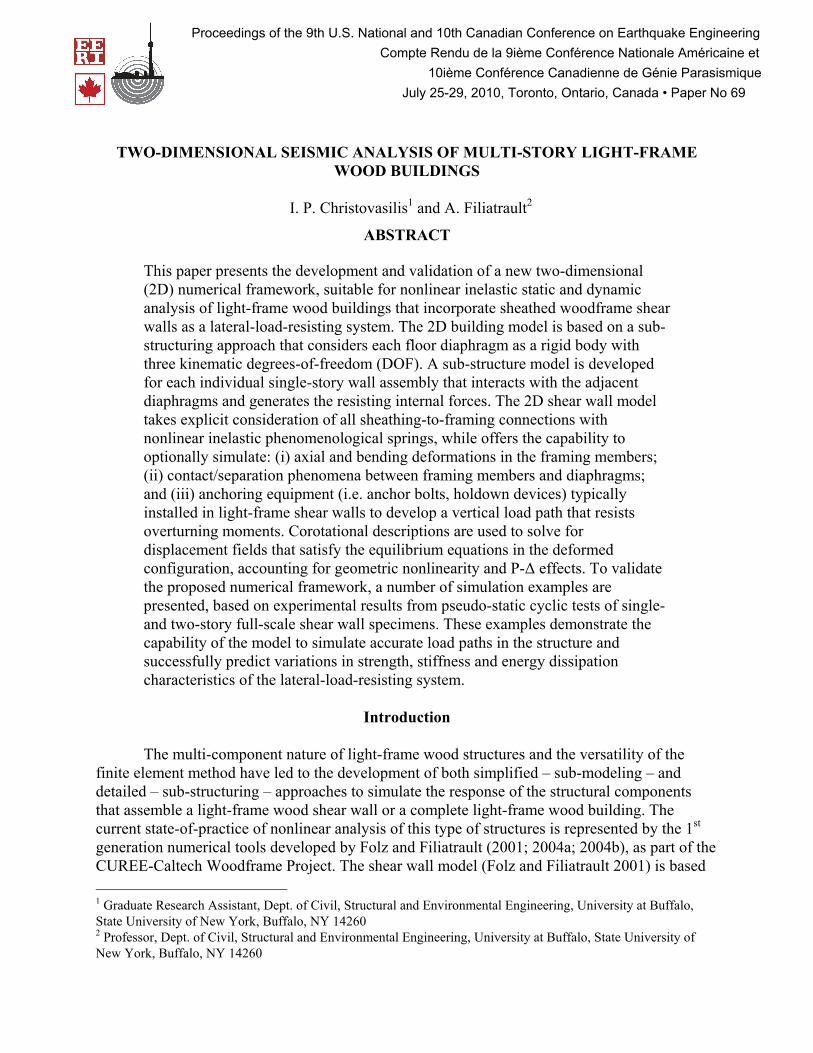
represent the inertial forces in the global level; and (ii) to use a sub-structuring approach to condense out the numerous DOF of each detailed shear wall model, maintaining only the associated master DOF. An efficient selection of master DOF is those associated with the motion and the deformation of the floor diaphragms. If floor diaphragms are considered to be rigid bodies, then three DOF in the 2D wall plane – two translations and one rotation – are sufficient to describe the equilibrium equations for each body, as shown in Fig. 1b. Utilizing the diaphragms as boundary elements of the sub-structures developed for each inter-story wall assembly allows the simulation of other modes of deformation (i.e. flexural and rocking modes) with due consideration of the interaction effects between shear walls and floor diaphragms. This eventually leads to a shear wall sub-structure for each story of the building that is effectively defined as a 2-noded, 6 DOF, displacement-based shear wall element, as shown in Fig. 1c, and exhibits axial, shear and moment interaction.
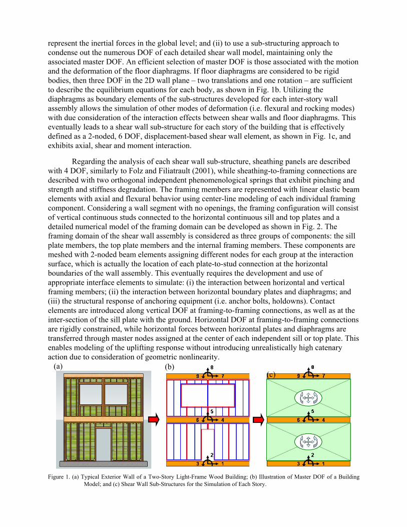
Regarding the analysis of each shear wall sub-structure, sheathing panels are described with 4 DOF, similarly to Folz and Filiatrault (2001), while sheathing-to-framing connections are described with two orthogonal independent phenomenological springs that exhibit pinching and strength and stiffness degradation. The framing members are represented with linear elastic beam elements with axial and flexural behavior using center-line modeling of each individual framing component. Considering a wall segment with no openings, the framing configuration will consist of vertical continuous studs connected to the horizontal continuous sill and top plates and a detailed numerical model of the framing domain can be developed as shown in Fig. 2. The framing domain of the shear wall assembly is considered as three groups of components: the sill plate members, the top plate members and the internal framing members. These components are meshed with 2-noded beam elements assigning different nodes for each group at the interaction surface, which is actually the location of each plate-to-stud connection at the horizontal boundaries of the wall assembly. This eventually requires the development and use of appropriate interface elements to simulate: (i) the interaction between horizontal and vertical framing members; (ii) the interaction between horizontal boundary plates and diaphragms; and (iii) the structural response of anchoring equipment (i.e. anchor bolts, holdowns). Contact elements are introduced along vertical DOF at framing-to-framing connections, as well as at the inter-section of the sill plate with the ground. Horizontal DOF at framing-to-framing connections are rigidly constrained, while horizontal forces between horizontal plates and diaphragms are transferred through master nodes assigned at the center of each independent sill or top plate. This enables modeling of the uplifting response without introducing unrealistically high catenary action due to consideration of geometric nonlinearity. .
Figure 1. (a) Typical Exterior Wall of a Two-Story Light-Frame Wood Building; (b) Illustration of Master DOF of a Building
Model; and (c) Shear Wall Sub-Structures for the Simulation of Each Story.
(a) (c)
(b)
Figure 2. Detailed Numerical Model of the Framing Domain.
This formulation also enables modeling of anchoring devices by introducing springs that connect corresponding vertical DOF of the framing with the diaphragms. Finally, the use of corotational descriptions of the displacement fields of the finite elements implemented in the proposed numerical framework accounts for geometric nonlinearity associated with large rotations and for P-Δ effects due to gravity loads, assuming small deformations of the structural members that remain linear elastic, such as the individual framing members and the sheathing panels. This results in a shear wall element that satisfies equilibrium in the deformed configuration and is applicable for nonlinear analysis up to complete failure of the lateral-load-resisting system and side-sway collapse of the structure. Due to space limitations, the analytical derivations developed within this research study are not presented in this paper. This analytical background can be found in Christovasilis and Filiatrault (2009) and Christovasilis (2010).
Numerical Predictions This section presents the comparison of global responses – inter-story displacements versus inter-story forces – between experimental and numerical data, generated for two single-story groups and one two-story group of full-scale shear wall specimens. The selected experimental data have been generated by Pardoen et al. (2003) within the CUREE-Caltech Woodframe Project. Two numerical predictions are illustrated throughout the various figures. One is labeled Pure Shear and represents a numerical model that considers nonlinear inelastic action solely at the sheathing-to-framing connections, assuming a pure kinematic distortion of rigid framing members and fixed plate-to-diaphragm boundary conditions. The second prediction is labeled Model and represents the proposed numerical framework that accounts for framing flexibility and nonlinear phenomena between framing members and diaphragms.

The wall dimensions of all single-story specimens were equal to 16ft long by 8ft high, as shown in Fig. 3. The first configuration consisted of four panels forming a Fully Sheathed (FS) wall, while the second configuration incorporated a Garage Door (GD) with one wall segment at each end with a relatively high AR of 2.5. The framing consisted of nominal 2x4 studs spaced at 16in on center (o.c.), using Douglas–Fir lumber graded No. 1 or better. The sheathing provided was Oriented Strand Board (OSB), 3/8in thick. Sheathing panels were fastened to the framing with 8d box gun nails, 2.5in long with 0.113in diameter. Edge nailing was specified at 6in o.c. for the FS wall and at 3in o.c. for the GD wall. Specific anchorage equipment was installed at the end posts of each full-height shear wall segment, as shown in Fig. 3. More information on the geometric and structural characteristics of the shear wall specimens can be found in Pardoen et al. (2003), while the properties and parameters utilized in the constitutive models are presented in Christovasilis (2010). Two identical specimens of each group were tested under displacement-controlled cyclic loading using the CUREE protocol (Krawinkler et al. 2003). The total weight acting at the top of each single-story specimen was estimated at 2000lbs. Figure 4 illustrates the cyclic pushover test results for two different test specimens (labels Test A and Test B) along with the numerical Model predictions, for the two wall configurations. In general, the predicted cyclic behavior is well correlated with the experimental response exhibiting in-cycle and cyclic strength degradation and pinching characteristics, consistent with the test observations. Figure 5 illustrates the monotonic and cyclic pushover curves on the left column and the associated cumulative strain energy dissipation from the cyclic responses on the right column, including both numerical responses. These summarizing figures show that the Pure Shear responses tend to predict not only higher stiffness and strengths, but also fatter hysteresis loops during pinching response. This difference is more pronounced for the GD wall leading to significant overestimation of the energy dissipation capability. The energy dissipation capability predicted by the Model responses is consistently lower than the energy dissipated by the Test responses but the overall rate of dissipation is reasonably predicted throughout the deformation ranges.
Figure 3. (a) Geometric and Panel Configurations; and (b) Numerical Models of the Single-Story Shear Walls.
(a) (b)
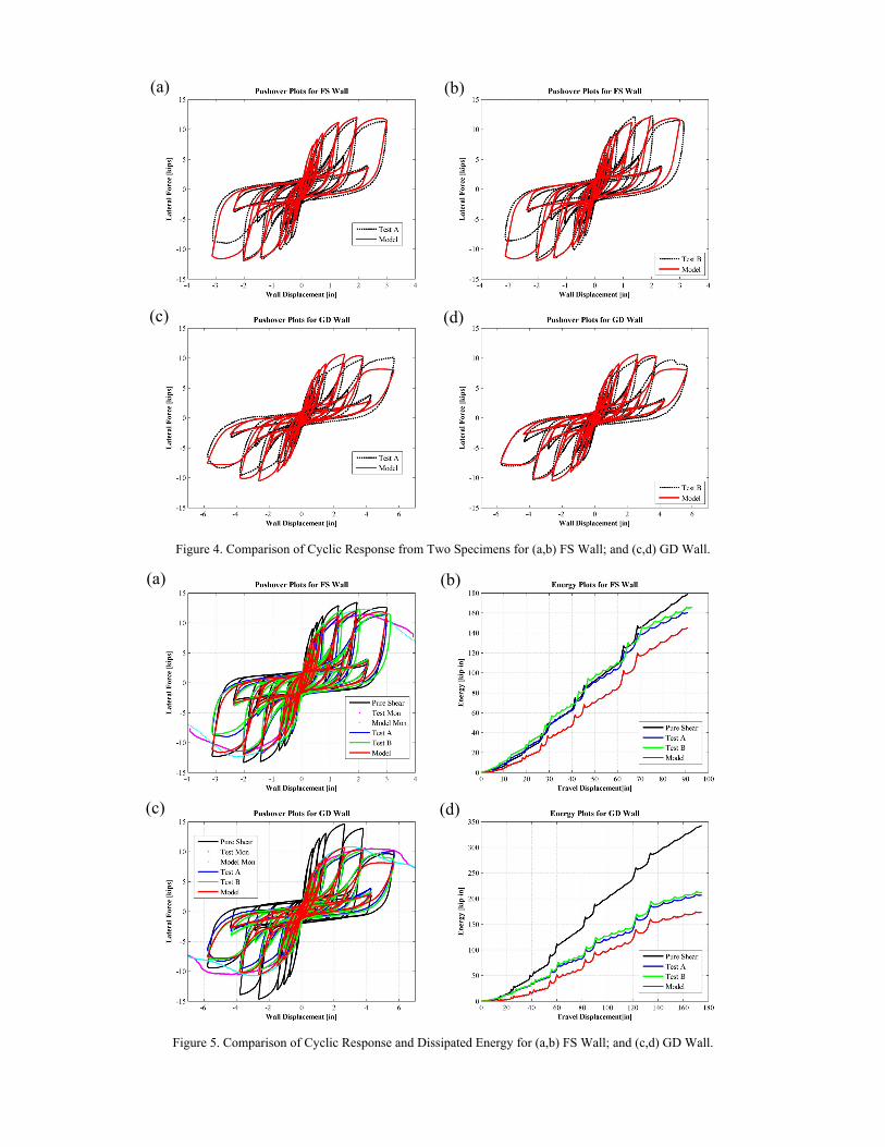
Figure 4. Comparison of Cyclic Response from Two Specimens for (a,b) FS Wall; and (c,d) GD Wall.
Figure 5. Comparison of Cyclic Response and Dissipated Energy for (a,b) FS Wall; and (c,d) GD Wall.
(a) (b)
(c) (d)
(a) (b)
(c) (d)

Beside the single-story shear wall tests, Pardoen et al. (2003) performed pseudo-static testing of two-story light-frame wood shear walls. One specimen, which was tested under cyclic loading, has been considered in this example. The dimensions of the two-story specimen were equal to 16ft long by 17ft high, as shown in Fig. 6. Each story had a clear height of 8ft, while the diaphragm between the two stories was 1ft high. The first story incorporated a pedestrian door opening, while the second story incorporated two large window openings in the mid span of the wall. The structural components were the same as the single-story specimens and edge nailing was specified at 6in o.c. for both stories. The total weight acting at the top of the walls was estimated at 2800lbs and 2000lbs for the first and second story, respectively. This specimen, denoted as PD2S wall, was identical to the east side of the two-story full-scale light-frame wood house tested in the University of California, San Diego, within a shake-table task of the CUREE-Caltech Woodframe Project (Fischer et al. 2001). Figure 7 illustrates experimental and predicted hysteretic force-displacement responses for each story.
Figure 6. (a) Geometric and Panel Configurations; and (b) Numerical Models of the Two-Story Shear Wall.
Figure 7 Comparison of Cyclic Response for PD2S Wall.
(a) (b)

Commenting on the responses of the first-story wall, Model predictions are very well correlated to the experimental envelope curves up to the development of the ultimate strength. Force-displacement characteristics of the virgin loading curves are well predicted for inter-story displacements that are less than 3in. Past these displacement ranges, the Test responses demonstrate strength and stiffness degradation that the Model responses do not predict. The Model predictions of the responses of the second-story walls are in relatively good agreement with the experimental results. Predicted and experimental forces of the envelope curve are very well correlated. However, the energy dissipation capability is under-estimated predicting unloading curves that recover a greater part of the accumulated strain energy than what was observed experimentally. This may be attributed to inelastic action in uplift-restraint connections that are not included in the model. Figure 8 illustrates global experimental and numerical responses that include both Model and Pure Shear predictions, as well as the strain energy absorbed in each story. Concentrating first on the first-story wall, the Pure Shear responses predict about 5-10% higher forces than the Test responses. Similarly to what was observed for single-story walls with wall segments of low aspect ratio, the Pure Shear predictions dissipate more energy than the Model predictions but the overall hysteretic response is not significantly different between both numerical models. On the contrary, the Pure Shear predictions for the second-story walls demonstrate significant overestimation of the developed forces compared to the Model and Test responses. Maximum forces from the Pure Shear predictions are more than 30% higher than the experimental forces.
Figure 8. Comparison of Cyclic Response and Dissipated Energy for PD2S Wall.

Deformed Shape of Garage Door Figure 9 illustrates close-up view images of the GD wall specimen at three locations after testing along with the deformed shape of the numerical model. Figure 9c shows the cross-grain crushing of the sill plate under compressive load carried from the stud above. This mode of deformation is not considered in the proposed model, but could be integrated in the response of the contact spring that connects the sill plate and the stud. Figure 9b focuses on the connection of the header with the inner studs. It is shown that the header has actually separated from the jack studs, while the full height stud has also detached from the top plate. This is similar to what is shown in Fig. 9a and justifies the modeling technique of the GD wall regarding the header, given that separation between framing members is not considered within the wall but only between sill/top plates and studs. The horizontal beam representing the header has a high axial and bending stiffness but the sheathing panel covering the header is not nailed along the bottom edge. This allows the vertical studs of the full height pier to separate from the top plate, without imposing additional tensile strength from the header. Figure 9d focuses on the bottom of the wall end that is under tensile vertical forces. Again, the observed deformed shape matches the predicted deformed shape shown in Fig. 9a. The outer and the field stud has uplifted from the sill plate, while the studs anchored with the holdown remain connected to the sill plate. These correlations demonstrate that the proposed numerical framework predicts realistic load paths within the shear wall domain and can capture variations of the global stiffness, strength and energy dissipation capability of shear wall assemblies with various geometric and structural configurations.
Conclusions
In general, the global inter-story hysteretic response is predicted very well by the Model formulation, independently of the structural and geometric characteristics of the shear wall. This is better understood when considering that numerical predictions of the Pure Shear formulation achieve a good correlation for the first-story walls with low Aspect Ratio (AR) wall segments – below a value of 2 – but significantly over-estimate stiffness, strength and energy dissipation characteristics of wall segments with high AR as well as the second-story wall. The consideration of framing flexibility and contact/separation between framing members and diaphragms leads to better estimates of the actual response by modifying the force and displacement characteristics that result in more flexible responses, compared to the Pure Shear responses, with lower energy dissipation capability. The effectiveness of the proposed model is more pronounced for (i) the GD wall, which consisted of two high AR wall piers, and (ii) the second-story of the PD2S wall, in the sense that for these cases the difference between the two numerical predictions is significant.
Acknowledgments The material presented in this paper is based upon work supported by the National Science Foundation under Grant No. CMMI-0529903 (NEES Research) and CMMI- 0402490 (NEES Operations). Any opinions, findings, and conclusions or recommendations expressed in this material are those of the author(s) and do not necessarily reflect the views of the National Science Foundation.

Figure 9. Correlation of Deformation Patterns between Numerical (a) and Experimental (b,c,d) Deformed Shapes.
References
ASCE, 2006. Minimum Design Loads for Buildings and Other Structures, ASCE Standard ASCE/SEI 7-05, including Supplement No. 1, American Society of Civil Engineers, Reston, Virginia.
Christovasilis, I.P. 2010. “Numerical and Experimental Investigations of the Seismic Response of Light-Frame Wood Structures”, Ph.D. Thesis, University at Buffalo, State University of New York, Buffalo, NY.
Christovasilis, I.P. and Filiatrault, A. 2009. “Two-dimensional Numerical Modeling of Light-frame Wood Structures for Seismic Collapse Assessment”, Proceedings of COMPDYN 2009 – Computational Methods in Structural Dynamics and Earthquake Engineering, Rhodes, Greece.
Christovasilis, I.P., Filiatrault, A. and Wanitkorkul, A., 2007. “Seismic Testing of a Full-Scale Two-Story Light-Frame Wood Building: NEESWood Benchmark Test,” NEESWood Report No. NW-01, Dept. of Civil, Structural and Environmental Engineering, State University of New York at Buffalo, Buffalo, New York.
Christovasilis, I.P., Filiatrault, A., Wanitkorkul, A. and Constantinou, M.C., 2008. “Incremental Dynamic Analysis of Woodframe Buildings”, Journal of Earthquake Engineering and Structural Dynamics 38 (4):477-496.
FEMA, 2009. Quantification of Building Seismic Performance Factors, FEMA P695, Prepared by the Applied Technology Council (ATC), Federal Emergency Management Council (FEMA), Washington, D.C.
Fischer, D., Filiatrault, A., Folz, B., Uang, C. M. and Seible, F., 2001. “Shake Table Tests of a Two-Story Woodframe House,” CUREe Publication No. W-06, CUREE-Caltech Woodframe Project.
Folz, B. and Filiatrault, A., 2001. “Cyclic Analysis of Wood Shear Walls,” Journal of Structural Engineering, ASCE, 127(4):433-441.
Folz, B. and Filiatrault, A., 2004a. “Seismic Analysis of Woodframe Structures I: Model Formulation,” Journal of Structural Engineering, ASCE, 130 (9):1353-1360.
Folz, B. and Filiatrault, A., 2004b. “Seismic Analysis of Woodframe Structures II: Model Implementation and Verification,” Journal of Structural Engineering, ASCE, 130 (9):1361-1370.
Krawinkler, H., Parisi, F., Ibarra, L., Ayoub, A. and Medina, R., 2003. “Development of a Testing Protocol for Woodframe Structures”, CUREe Publication No. W-02, CUREE-Caltech Woodframe Project.
Pardoen, G.C., Walman, A., Kazanjy, R.P., Freund, E. and Hamilton, C.H., 2003. “Testing and Analysis of One-Story and Two-Story Shear Walls Under Cyclic Loading,” CUREe Publication No. W-25, CUREE-Caltech Woodframe Project.
(c) (b)
(d)
(a)