
Two-dimensional nonlinear inversion of seismic waveforms ...
Directional Scale Analysis for Three Dimensional SeismicInterpretation
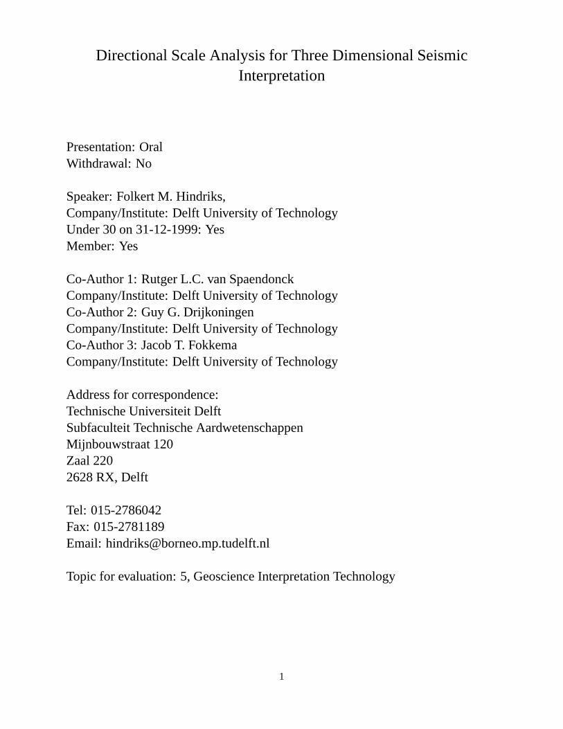
Presentation: OralWithdrawal: No
Speaker: Folkert M. Hindriks,Company/Institute: Delft University of TechnologyUnder 30 on 31-12-1999: YesMember: Yes
Co-Author 1: Rutger L.C. van SpaendonckCompany/Institute: Delft University of TechnologyCo-Author 2: Guy G. DrijkoningenCompany/Institute: Delft University of TechnologyCo-Author 3: Jacob T. FokkemaCompany/Institute: Delft University of Technology
Address for correspondence:Technische Universiteit DelftSubfaculteit Technische AardwetenschappenMijnbouwstraat 120Zaal 2202628 RX, Delft
Tel: 015-2786042Fax: 015-2781189Email: [email protected]
Topic for evaluation: 5, Geoscience Interpretation Technology
1
SummaryA combined space-Fourier representation focused on directional scale analysis is presented. The methodleads to a space vs. log polar frequency distribution. Application to three dimensional seismic data showsdifferentiation in scale and dip direction. Attributes are extracted to illustrate this differentiation.
IntroductionA widespread tool in signal and image processing is multi-scale decomposition. These time-frequency
distributions provide a new tool to get more insights into seismic data (Steeghs, 1997). Three dimensionalseismic data contains three basic components: amplitude, frequency and geometry. We try to find seismicattributes to describe the data in terms of these three components. The motivation for the use of a multi-scaledecomposition is that the earth’s response appears through different scales of resolution, and the structuralinformation through different angles (van Spaendonck and Baraniuk, 1999).We use a polar scale decomposition or ’steerable pyramid’. The operator results in a scale decompositionalong certain bands of orientations, and can hence be used for directional scale analysis. The filters aredesigned in the Fourier domain.In this paper we focus on the extraction of local (polar) scale and local geometrical information to improveconventional 3-D interpretation methods. In the next sections we will shortly address 2-D polar scale decom-position, followed by the extension to three dimensions. We conclude with some examples of the extractedattributes, performed on 3-D migrated seismic data.
Steerable PyramidThe wavelet transform is basically a set of bandpass filters applied to the input image and down sampledsubsequently. If these filters are applied in the Fourier domain we speak of filterbanks. The bandpass fil-
+!x
+!t
.........
.........
.......................................................
.....................
.......................
...........................
....................................
.................................................................................................................................................................................................................................................................................................................................................................................................................................................................................................................................................................................................
......................................
.............................
.................................................................................................................................
............................
.....................
..................................
..................................................................................................................................................................................................................................................................................................................
..........................................................................
...................
....................................................................................................................................................................
.................................
���
@@@
@@@
���
H0
L2
H�11
H�12
H�11
H�12
H�21
H�22
H�21
H�22
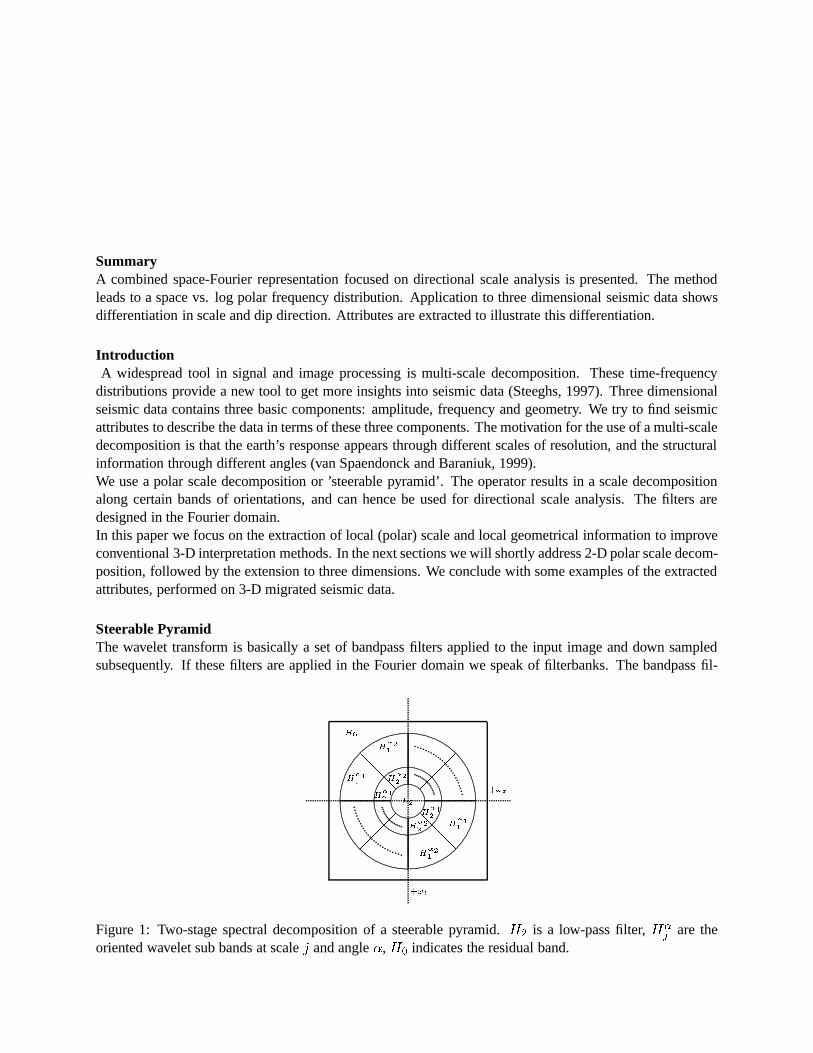
Figure 1: Two-stage spectral decomposition of a steerable pyramid.H2
is a low-pass filter,H�j are the
oriented wavelet sub bands at scalej and angle�, H0
indicates the residual band.
ters (filterbanks) are obtained by cascading low- and high-pass filters. For directional analysis, the Fourierdomain may better be parameterized in terms of polar coordinates. The angular coordinate corresponds toorientation and the (logarithmic) radial component corresponds to polar frequency (scale) at that specificorientation (van Spaendonck and Baraniuk, 1999). Translation of a signal in this two dimensional log polarFourier domain corresponds to dilation and rotation of the signal in the spatial domain. The sub bands arepolar separable. The transform with this characteristic partitioning is called a steerable pyramid (Freemanand Adelson, 1991). The steerable pyramid can be designed either in the spatial or in the Fourier domain.Figure (1) shows this 2-D Fourier domain partitioning for two scales and four orientation bands. The filter-banks are constructed according to the following scheme (Simoncelli et al., 1992):
H�j (!) = L(
!
2j�1)H(
!
2j)B�(!) (1)
in which the polar low- and high-pass filters are indicated byL(!) andH(!), the bandpass filters byB�(!), where� denotes the angle band, and! = (!x; !t), in which!t denotes the temporal frequencyand!x denotes the spatial frequency. Since the input data is assumed to be real (migrated) seismic data, wecan perform a Hilbert transform along the polar axes of the orientated bandpass filters. The Hilbert trans-form is performed by applying the operatorU(!) = (1 + !
j!j) in the direction ofir = !
j!j, in the Fourier
domain.The steerable pyramid computed in this fashion returns a real part and an imaginary part in quadrature. Inview of wave propagation this envelope of the filtered signal is a measure for instantaneous energy (Claer-bout, 1995). Because the real and imaginary part are in quadrature, the envelope is not interfered by zero-crossings in the input image.
+!x
+!y
.........
.........
...............................................
.....................
........................
.................................
..........................................................................................................................................................................................................................................................................................................................................................................................................................................................................................................
....................................
............................................................................................................................
............................
.........................
.................................................................................................................................................................................................................................................................
..........................................................................
.......................
................................................................................................................................................................
���
@@@
@@@
���
H0
L2H�11
H�31
H�21
H�41
+!x
+!t
.........
..............................................
....................
......................
............................
...............................................
.................................................................................................................................................................................................................................................................................................................................................................................................................................................................................................
.............................
...............................................................................................................
............................
.........................
.................................................................................................................................................................................................................................................................
..........................................................................
.......................
................................................................................................................................................................
���
@@@
@@@
���
����
����
XXXX
XXXX
����
CCCC
����
CCCC
H0
L2H�11
H�11
H�41
H�41
H�21
H�21
H�21
H�21
H�31
H�31
H�31
H�31
+!y
+!t
.........
........................................................
.....................
........................
.................................
..........................................................................................................................................................................................................................................................................................................................................................................................................................................................................................................
....................................
............................................................................................................................
............................
.........................
.................................................................................................................................................................................................................................................................
..........................................................................
.......................
................................................................................................................................................................
���
@@@
@@@
���
����
����
XXXX
XXXX
����
CCCC
����
CCCC
H0
L2H�11
H�11
H�41
H�41
H�21
H�21
H�21
H�21
H�31
H�31
H�31
H�31
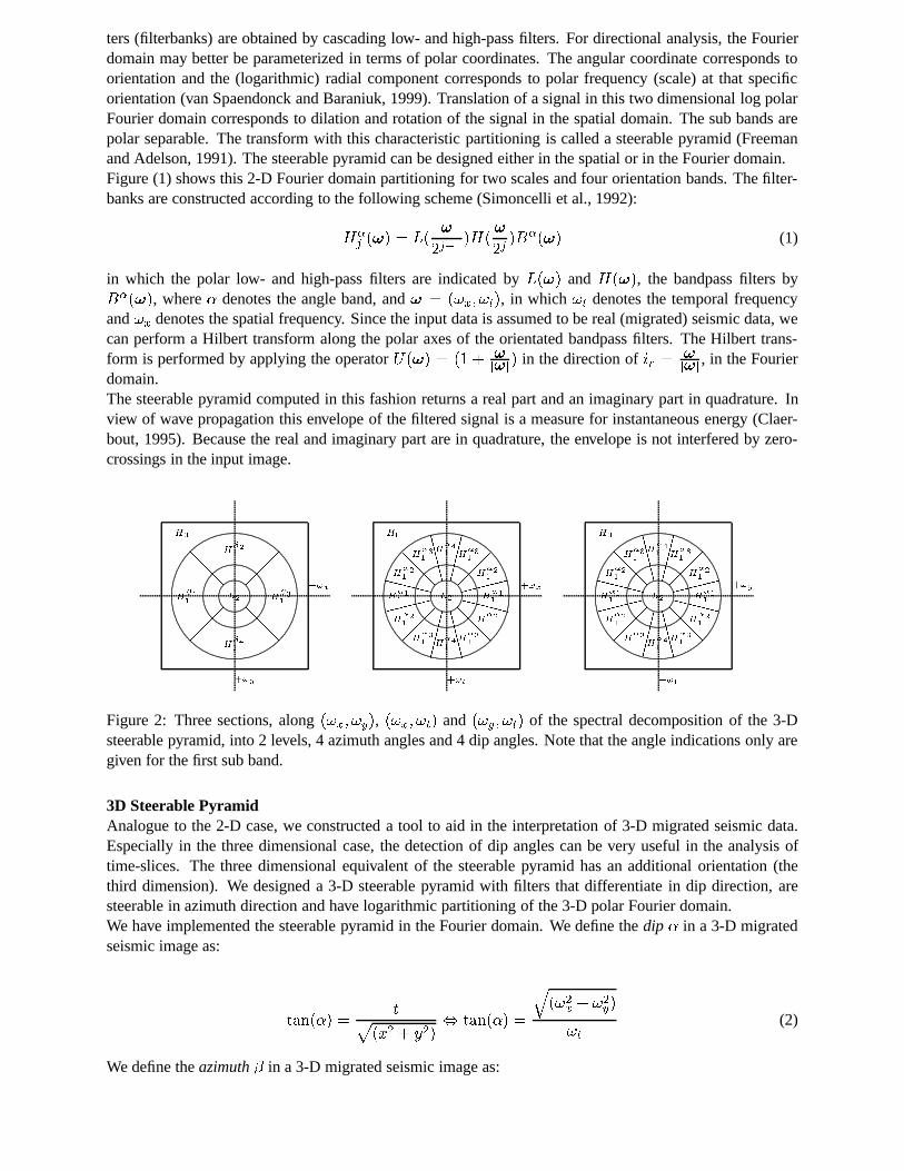
Figure 2: Three sections, along(!x; !y), (!x; !t) and (!y; !t) of the spectral decomposition of the 3-Dsteerable pyramid, into 2 levels, 4 azimuth angles and 4 dip angles. Note that the angle indications only aregiven for the first sub band.
3D Steerable PyramidAnalogue to the 2-D case, we constructed a tool to aid in the interpretation of 3-D migrated seismic data.Especially in the three dimensional case, the detection of dip angles can be very useful in the analysis oftime-slices. The three dimensional equivalent of the steerable pyramid has an additional orientation (thethird dimension). We designed a 3-D steerable pyramid with filters that differentiate in dip direction, aresteerable in azimuth direction and have logarithmic partitioning of the 3-D polar Fourier domain.We have implemented the steerable pyramid in the Fourier domain. We define thedip � in a 3-D migratedseismic image as:
tan(�) =tp
(x2 + y2), tan(�) =
q(!2x + !2y)
!t(2)
We define theazimuth� in a 3-D migrated seismic image as:
tan(�) =y
x, tan(�) =
!x
!y(3)
The 3-D steerable pyramid is constructed by cascading (and subsequently down sampled) polar low- andhigh-pass filters. The resulting bandpass filters are divided inM dip bands. For one dip band the azimuthalsub bands are polar separable. TheM dip bands in turn are divided intoK azimuthal bands. The low- andhigh-pass filters are indicated byL(!) andH(!), the bandpass filters byB�;�(!), and! = (!x; !y; !t).The filterbanksH�;�
j (!) are then computed by:
H�;�j (!) = L(
!
2j�1)H(
!
2j)B�;�(!) (4)
The filters are designed in such a manner that we can reconstruct the original image by applying the samefilters to the filtered data. For perfect reconstruction we constrain the filters by:
jH(!
2j)j2 + jL(
!
2j)j2 = 1; for j = 1; 2; :::; N; (5)
�MX�=�1
�KX�=�1
jB�;�(!)j2 = 1; (6)
in whichN is the number of scales,�M gives the number of dip-bands and�K gives the number of azimuth-bands. Furthermore, we constrain the filters to be real. A schematic view of this 3-D steerable pyramid isgiven in figure (2).The 3-D steerable pyramid representation can be made complex by applying a Hilbert transformation. Weapplied a Hilbert transform in the!t direction:
U(!x; !y; !t) = f0; 1; 2g for f!t < 0; !t = 0; !t > 0g (7)
As in the 2-D case the steerable pyramid returns a real and an imaginary part in quadrature, which has ad-vantages for attribute extraction..
Seismic data exampleWith the complex steerable pyramid we can extract several attributes. We extracted attributes for local dip,local azimuth and local scale from the 3-D steerable pyramid. Local dip, local azimuth and local scale arecomputed by the first moment over dip, azimuth and scale in the following way:
local dip: < � >=
R R R�E(�; �; �)d�d�d�R R RE(�; �; �)d�d�d�
; (8)
local azimuth: < � >=
R R R�E(�; �; �)d�d�d�R R RE(�; �; �)d�d�d�
; (9)
local scale: < � >=
R R R�E(�; �; �)d�d�d�R R RE(�; �; �)d�d�d�
; (10)
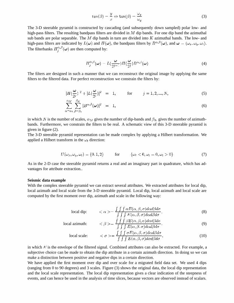
in whichE is the envelope of the filtered signal. Combined attributes can also be extracted. For example, asubjective choice can be made to obtain the dip attribute in a certain azimuth direction. In doing so we canmake a distinction between positive and negative dips in a certain direction.We have applied the first moment over dip and over scale for a migrated field data set. We used 4 dips(ranging from 0 to 90 degrees) and 3 scales. Figure (3) shows the original data, the local dip representationand the local scale representation. The local dip representation gives a clear indication of the steepness ofevents, and can hence be used in the analysis of time slices, because vectors are observed instead of scalars.

−4
−2
0
2
4
6x 10
4
20
40
60
1.5
2
2.5
Figure 3: Upper left: seismic data. Upper right: local dip attribute obtained from the data, with the colorbarindicating absolute dip value, independent of azimuth. Bottom: local scale attribute obtained from the data.
The local scale representation gives a good indication of the local frequency content, perpendicular to thestructure.
ReferencesClaerbout, J., 1992, Earth sounding analysis: processing versus inversion (PVI), Blackwell Science.
Freeman, W., and Adelson, E., 1991, The design and use of steerable steerable filters: IEEE Pat. Anal.Mach. Intell.,13, no.9, 891-906.
Simoncelli, E., Freeman, W., Adelson, E., and Heeger, D., 1992, Shiftable multi-scale transforms: IEEETransactions on Information Theory.,38, 587-607.
Spaendonck, R. van, and Baraniuk, R., 1999, Directional scale analysis for seismic interpretation: SEGExpanded abstracts, 1844-1847.
Steeghs, T., 1997, Local power spectra and seismic interpretation: Ph.D. thesis, Delft University of Tech-nology.


