Twist outlet for ceiling installation, DD-N · Twist outlets for ceiling installation are proven...
14
Krantz Components Air distribution systems Twist outlet DD-N.... for ceiling installation DS 1175 E 06.2014
Transcript of Twist outlet for ceiling installation, DD-N · Twist outlets for ceiling installation are proven...

Krantz Components
Air distribution systems
Twist outlet DD-N....for ceiling installation
DS 1175 E 06.2014
2 Krantz Components
ww
w.k
rant
z.de
D
S 1
175
E
p. 2
0
6.20
14
ww
w.k
rant
z.de
D
S 1
175
E
p. 3
0
6.20
14
Twist outletPreliminary remarks and construction design
Preliminary remarks
Twist outlets for ceiling installation are proven air outlets from Krantz Components for the commercial and industrial sectors. Thanks to their favourable aerodynamics and acoustics, their at-tractive appearance and easy installation, these outlets have been put to successful use for decades. They are particularly suitable for commercial rooms with high-quality indoor air flow requirements such as office buildings, schools, hospitals, etc.
Construction design
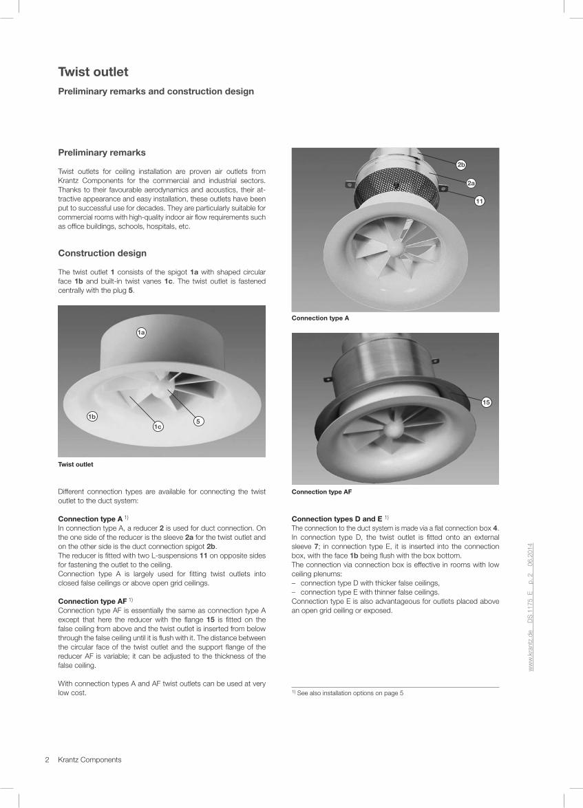
The twist outlet 1 consists of the spigot 1a with shaped circular face 1b and built-in twist vanes 1c. The twist outlet is fastened centrally with the plug 5.
1a
1b5
1c
Twist outlet
Different connection types are available for connecting the twist outlet to the duct system:
Connection type A 1)
In connection type A, a reducer 2 is used for duct connection. On the one side of the reducer is the sleeve 2a for the twist outlet and on the other side is the duct connection spigot 2b. The reducer is fitted with two L-suspensions 11 on opposite sides for fastening the outlet to the ceiling. Connection type A is largely used for fitting twist outlets into closed false ceilings or above open grid ceilings.
Connection type AF 1)
Connection type AF is essentially the same as connection type A except that here the reducer with the flange 15 is fitted on the false ceiling from above and the twist outlet is inserted from below through the false ceiling until it is flush with it. The distance between the circular face of the twist outlet and the support flange of the reducer AF is variable; it can be adjusted to the thickness of the false ceiling.
With connection types A and AF twist outlets can be used at very low cost.
2a
2b
11
Connection type A
15
Connection type AF
Connection types D and E 1)
The connection to the duct system is made via a flat connection box 4. In connection type D, the twist outlet is fitted onto an external sleeve 7; in connection type E, it is inserted into the connection box, with the face 1b being flush with the box bottom.The connection via connection box is effective in rooms with low ceiling plenums: – connection type D with thicker false ceilings, – connection type E with thinner false ceilings.
Connection type E is also advantageous for outlets placed above an open grid ceiling or exposed.
1) See also installation options on page 5

3Krantz Components
ww
w.k
rant
z.de
D
S 1
175
E
p. 2
0
6.20
14
ww
w.k
rant
z.de
D
S 1
175
E
p. 3
0
6.20
14
Twist outlet Mode of operation, return air inlets, sound power level and pressure drop
In general: With all connection types the twist outlet is inserted from below and fastened at the plug 5 with a central screw 10. A side of the connection box is fitted with a spigot 8 for connection to a flexible or spiral seam duct. This spigot may be fitted with a volume flow damper 9 adjustable from the room.The connection box is also available with acoustic lining for higher insertion loss. The advantages of the connection box are low height, simple volume flow rate setting and good insertion loss.
7
8
4
Connection type D
9
Connection type E
Perforated cover screenWhere a visually plane ceiling surface is required, a perforated cover screen is available for the twist outlet. This cover screen is fastened from below with the central screw 10.
Twist outlet with perforated cover screen
Mode of operation
The vanes of the air outlet produce a twist effect and the curved exit causes an additional horizontal jet deflection. The horizontal, radial jets bring about an intensive admixture of indoor air and, as a result, rapid equalization of supply air temperature with indoor air temperature. Twist outlets from Krantz Components belong to the diffuse air distribution system where there is no steady air jet pattern in the occupied zone. Thanks to the very high induction effect of the supply air jets, the vertical and horizontal temperature distribution is extremely even in air-conditioned rooms. Twist outlets can be used up to a temperature difference of –12 K when cooling and +5 K when heating.
Return air inlets
Twist outlets can also be used as return air inlets. This applies for all connection types. A return air inlet with cover screen (without twist vanes) is also part of our standard range of products.
Sound power level and pressure drop
Typical features of Krantz Components twist outlets are low sound power level and pressure drop. These depend on size, connection type and volume flow rate. For example, for a DN 250 twist outlet with connection type D and a volume flow rate of about 110 l/s [400 m3/h]: – sound power level = 39 dB(A) ref. 10-12 W – pressure drop = 47 Pa.
For diagrams and tables see pages 8 – 12.

4 Krantz Components
ww
w.k
rant
z.de
D
S 1
175
E
p. 4
0
6.20
14
ww
w.k
rant
z.de
D
S 1
175
E
p. 5
0
6.20
14
Twist outletDesign specifications and features
Design specifications
The twist outlets can be installed in closed false ceilings, visibly, or above open grid ceilings, i.e. invisible from the room. This is made very easy by the different connection types. The vertical distance between the upper edge of the open grid ceiling and the discharge level should be ³ 1 x DN.In air distribution with twist outlets, supply air and return air open- ings may be located close together. Disruptions in jet dispersion or short-circuiting are ruled out if the height difference between the lower edge of the return air opening and the discharge level of the twist outlet is kept to min. 250 mm. If the twist outlet and the return air opening are at the same level, the horizontal centre spacing should amount to at least five times the nominal diameter (5 x DN).
Features
• Diffuse air distribution system
• Maximum temperature difference between supply air and indoor air: –12 K when cooling, +5 K when heating (+10 K up to 3 m room height)
• Stable jet pattern also at minimum volume flow rate
• Discharge height from 2.2 to 4.5 m
• Low sound power level
• Installation options: inside a false ceiling, above an open grid ceiling, or exposed
• Twist element easy to mount from below and to fasten with central screw
• Twist element made from polystyrene or aluminium
• Optionally available with perforated cover screen for visually plane ceiling surface
• Connection types A and AF with reducer for connection to flexible duct
• Connection types D and E with connection box and spigot; con-nection box D with built-in volume flow damper adjustable from room; connection box E with volume flow damper adjustable at the spigot or from room; connection boxes D and E optionally available with acoustic lining
• The twist outlets (with all connection types) can also be used as return air inlets
• A return air inlet with cover screen is available as standard for sizes DN 100 to DN 355
1 x
DN
Concrete ceiling Return air duct
Twist outlet Open grid ceiling Supply air duct
Example of supply air distribution via twist outlets above an open grid ceiling. The return air is removed evenly over the whole ceiling and extracted via a return air duct placed above the twist outlets.
Twist outlet installed in a closed false ceiling
Twist outlet in the entrance hall of DEA Mineralöl AG, Hamburg / D

5Krantz Components
ww
w.k
rant
z.de
D
S 1
175
E
p. 4
0
6.20
14
ww
w.k
rant
z.de
D
S 1
175
E
p. 5
0
6.20
14
Twist outletInstallation options
d =
a1
1)
1 x
DN
H3
1)
d
H5
1)
d
s
1 x
DN
H5
1)H
5 1)
1) See tables on pages 6 and 7
Connection type A Connection type D
Connection type E
Connection type AF
Installation in closed false ceiling
Placement above open grid ceiling
Reducer with flange for fitting on false ceiling. The size a1 isvariable; it corresponds to the thickness ‘d’ of the false ceiling.
Installation above open grid ceilings, particularly effective with very low plenums.
Visible installation (without false ceiling)
Installation in very thin false ceilings (from plasterboard or sheet metal) with low ceiling plenums. A seal is to be inserted by the client between the connection box and the false ceiling.
Open grid ceiling
Closed false ceiling
Installation in closed false ceiling with larger thickness (d < H3).

6 Krantz Components
ø DN + 30
ø D5
Y
ø D4 + 3 mm DN 180ø D4 + 4 mm > DN 180
17 17a
H1A
+ 1
mm
H6
5)
H6
5)
17b
17
H2A
H1A
ø DN + 30
ø D5
H3A
R
X
ø DN
ø D2 1)
ø D4
13
10
212
11
1
5
ø 9
ø D6
ø D5
H3A
F
R
ø DN
ø D2 1)
ø D4
15
a 1 2
)
H2A
F H1A
F
ø D7 ø D8
Connection type A
Detail X
Connection type AF
Connection type Awith perforated cover screen 4)
Detail Y
ww
w.k
rant
z.de
D
S 1
175
E
p. 6
0
6.20
14
ww
w.k
rant
z.de
D
S 1
175
E
p. 7
0
6.20
14
Twist outlet, connection types A and AFDimensions
Key for all pages Material
1 Twist outlet Polystyrene or aluminium
2 Reducer Aluminium
4 Connection box Galvanized sheet metal
5 Plug with internal thread Polystyrene or aluminium
6 Acoustic lining (optional)Mineral wool with
glass fibre mat, non-flammable
7 Sleeve 8 Connection spigot 9 Volume flow damper (optional)10 Fastener for twist outlet up to DN 180 with M6 thread from DN 250 with M8 thread 11 L-suspension 3) 12 Bore for suspension13 Suspension device13a Quick fastener (by others)13b Threaded rod (by others)14 Adjustment device for volume flow damper (optional)
Galvanized sheet metal or steel
15 Flange17 Perforated cover screen17a Spacer
Aluminium
17b Spacer ring (for DN 100 to DN 180)
—
Nom. ø Material of H1A H2A H3A H1AF H2AF H3AF H6 min5) D2
1) D4 D5 D6 D7 D8 R a12) Weight in kg
DN twist outlet mm mm mm mm mm mm mm mm mm mm mm mm mm mm mm A AF
100 Polystyrene 111 71 69 117 77 71 8 137 165 99 130 137 161 10 0 to 34 0.2 0.4
125 Polystyrene 152 112 98 160 120 101 8 172 200 99 155 172 200 23 0 to 63 0.2 0.5
160 Polystyrene 158 118 99 164 124 101 10 222 250 124 190 222 237 18 0 to 64 0.4 0.7
180 Polystyrene 179 139 127 183 143 126 10 247 280 159 212 252 280 34 0 to 92 0.5 1.0
250Polystyrene 236 196 160
239 199 156 12339
380 179 285 340 38045 0 to 120 0.9 1.5
Aluminium 211 171 135 300 25 0 to 95 1.3 1.9
315Polystyrene 287 247 200
289 249 196 15434
490 223 350 435 47560 0 to 160 1.6 2.3
Aluminium 250 210 163 378 32 0 to 123 2.1 3.0
355 Aluminium 292 232 178 255 215 156 18 426 550 249 390 427 467 36 0 to 138 2.7 4.0
1) Ceiling cutout 3) Size DN 355 has a third L-suspension offset at 90° 5) Other heights on request2) Variable 4) Also available for connection types AF, D and E

7Krantz Components
13a
ø 9 x 30
A
12
ø 9
13b
ø DN
ø D2 1)
ø D4
ø D
5
R
6
1
L1 L – 4
L
4
14
789
10
E
20L335
5
20
B2
B
B – 30
H H1
H7
t
B 15H
/2
H
EL3
ø DN
ø D2 1)
ø D4
ø D
5H
5 L2
L1
15L15
1
414 10
8 9
5
View ASuspension withquick fastener
Detail E
View ASuspension withthreaded rod M8and lock nuts
Connection box D
Connection box E
ww
w.k
rant
z.de
D
S 1
175
E
p. 6
0
6.20
14
ww
w.k
rant
z.de
D
S 1
175
E
p. 7
0
6.20
14
Twist outlet, connection types D and EDimensions 2)
Connection box D Connection box E
Nom. ø DN
Material of twist outlet
D21)
mmD4
mmR
mmL
mmB
mmB2
mmH
mmH1
mmH7
mmD5
mmL1
mmL3
mmt
mmW kg
L mm
B mm
H mm
H5
mmD5
mmL1
mmL2
mmL3
mmW kg
100 Polystyrene 137 165 10 165 180 90 125 174 49 99 40 110 25 1.8 300 300 135 18 99 95 35 171 1.6
125 Polystyrene 172 200 23 190 205 103 125 203 78 99 40 135 25 2.0 300 300 135 18 99 95 35 171 1.8
160 Polystyrene 222 250 18 225 240 120 150 229 79 124 40 170 30 2.8 380 380 180 28 124 95 35 251 2.4
180 Polystyrene 247 280 34 245 260 130 185 292 107 159 40 190 30 3.3 380 380 180 10 159 135 55 251 3.1
250Polystyrene 339
38045
315 330 165 225360 135
199 60 260 355.0
500 500 250 35 179 155 65 3714.9
Aluminium 300 25 335 110 5.4 5.3
315Polystyrene 434
49060
380 395 198 275450 175
249 60 325 357.0
600 600 250 13 223 200 90 4716.8
Aluminium 378 32 413 138 7.6 7.3
355 Aluminium 426 550 36 420 435 218 305 458 153 279 60 365 35 9.6 650 650 300 25 249 225 100 521 9.6
1) Ceiling cutout2) With perforated cover screen, see connection type A on page 6
8 Krantz Components
ww
w.k
rant
z.de
D
S 1
175
E
p. 8
0
6.20
14
ww
w.k
rant
z.de
D
S 1
175
E
p. 9
0
6.20
14
Twist outletComfort criteria
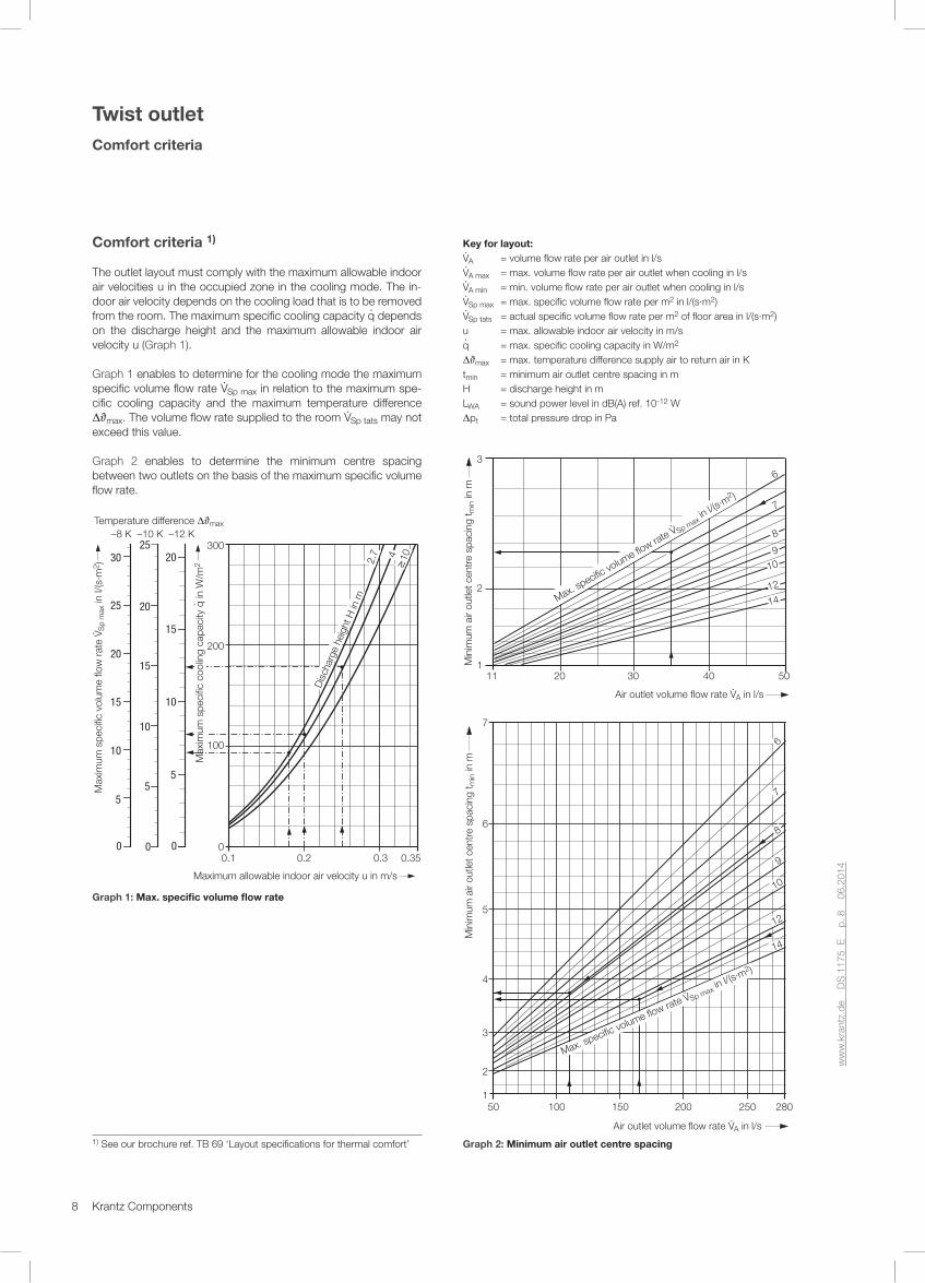
Comfort criteria 1)
The outlet layout must comply with the maximum allowable indoor air velocities u in the occupied zone in the cooling mode. The in-door air velocity depends on the cooling load that is to be removed from the room. The maximum specific cooling capacity q· depends on the discharge height and the maximum allowable indoor air velocity u (Graph 1).
Graph 1 enables to determine for the cooling mode the maximum specific volume flow rate V·Sp max in relation to the maximum spe-cific cooling capacity and the maximum temperature difference DJmax. The volume flow rate supplied to the room V·Sp tats may not exceed this value.
Graph 2 enables to determine the minimum centre spacing between two outlets on the basis of the maximum specific volume flow rate.
300
200
100
0
104
0.3 0.350.2
Maximum allowable indoor air velocity u in m/s
Dis
char
ge h
eigh
t H in
m2.
7
0.10
15
20
5
10
0
20
15
10
5
25
0
30
25
15
20
10
5
Max
imum
spe
cific
vol
ume
flow
rat
e V· S
p m
ax in
l/(s
·m2 )
Max
imum
spe
cific
coo
ling
capa
city
q· in W
/m2
Temperature difference max –8 K –10 K –12 K
Graph 1: Max. specific volume flow rate
1) See our brochure ref. TB 69 ‘Layout specifications for thermal comfort’
Key for layout: V·A = volume flow rate per air outlet in l/sV·A max = max. volume flow rate per air outlet when cooling in l/sV·A min = min. volume flow rate per air outlet when cooling in l/sV·Sp max = max. specific volume flow rate per m2 in l/(s·m2)V·Sp tats = actual specific volume flow rate per m2 of floor area in l/(s·m2)u = max. allowable indoor air velocity in m/s q· = max. specific cooling capacity in W/m2
DJmax = max. temperature difference supply air to return air in Ktmin = minimum air outlet centre spacing in mH = discharge height in m LWA = sound power level in dB(A) ref. 10-12 WDpt = total pressure drop in Pa
Max. specific volume flow rate V·
Sp max in l/(s
·m2 )
14
12
10
9
8
7
6
50 100 150 200 250 280
Air outlet volume flow rate V·A in l/s
1
2
3
4
5
6
7
Min
imum
air
outle
t cen
tre
spac
ing
t min in
m
11 504030201
2
3M
inim
um a
ir ou
tlet c
entr
e sp
acin
g t m
in in
m
Max. specific vo
lume flow rate V
· Sp max in l/(s
·m2 )
6
7
8
9
10
1412
Air outlet volume flow rate V·A in l/s
Graph 2: Minimum air outlet centre spacing

9Krantz Components
ww
w.k
rant
z.de
D
S 1
175
E
p. 8
0
6.20
14
ww
w.k
rant
z.de
D
S 1
175
E
p. 9
0
6.20
14
Twist outlet DN 100 – DN 355Connection types A, AF, D and E – Nomogram
The sound power levels for connection types A and AF apply for vertical air supply to the air outlet. The chart values for sound power level and pressure drop for connection types D and E apply for damper position ‘open’ and connection box without acoustic lining. With acoustic lining, the sound power levels are about 2 dB(A) lower than indicated in the chart. The pressure drop is not affected by the acoustic lining. For outlets with perforated cover screens, the sound power levels are approx. 2 to 4 dB(A) higher than indicated in the chart and the pressure drops about 10% higher.
Layout exampleSize (Connection type D) DN 160 DN 250 DN 315
Application Office BankDepartment
store1 Supply air volume flow rate V· l/s 2 200 5 5002 Discharge height H m 2.7 3.2 3.63 Floor area A m2 400 1 000 1 2004 Max. allowable sound power level LWA dB(A) ref.10-12 W
40
5 Comfort criteria (see page 8) – Max. allowable indoor air velocity u m/s – Max. specific volume flow rate V·Sp max at DJmax = –12 K l/(s·m2) – Actual specific volume flow rate V·Sp tats [from 1 : 3] l/(s·m2) Criterion is met if V·Sp tats < V·Sp max
0.18
6.5
5.5
0.2
7.8
5.5
0.25
12.5
4.6
From nomogram
Size DN 160 DN 250 DN 315
6 V·A max l/s 36 118 168
7 Z [V· : V·A] units 63 50 33
8 V·A [V· : Z] l/s 35 110 165
9 LWA dB(A) ref. 10-12 W » 27 » 38 » 38
10 Dpt Pa » 22 » 32 » 32
11 tmin [Graph 2 on page 8] m » 2.3 » 3.8 » 3.6
Anschlussart A AF D und E
1 000
500
400
300
200
100
50
40
V·A maxm3/h l/s
280
200
100
50
40
30
20
11
V·Al/s
280
200
100
50
40
30
20
112.2 3.0 4.0 5.0
DN 355
DN 315
DN 250
DN 180
DN 160
DN 100
DN 125
V·A minDN 160
V·A minDN 355
V·A minDN 180
V·A minDN 315
V·A minDN 100 a. DN 125
V·A minDN 250
30 40 5020 1003020 40 50
Discharge height H in m Sound power level LWA in dB(A) ref. 10-12 W Pressure drop pt in Pa
DN 355
DN 315
DN 250
DN 180
DN 160
DN 125
DN 100
DN 355
DN 315
DN 250
DN 180
DN 160
DN 125
DN 100
Connection type A and AF D and E
10
Connection type A and AF D and E

10 Krantz Components
Connection types A and AF Connection types D and E
Size
Air outlet volume flow rate
V·A
Total pressure drop 3)
Sound power level LW in dB ref. 10-12 W 1) Total pressure drop 2+3)
Sound power level LW in dB ref. 10-12 W 2)
LWA 3) Octave band centre frequency in Hz LWA
3) Octave band centre frequency in Hz
l/s m3/h Dpt in Pa dB(A) 125 250 500 1 000 2 000 4 000 Dpt in Pa dB(A) 125 250 500 1 000 2 000 4 000
DN 100
11 16 22 25
40 60 80 90
21 48 84 07
20 32 41 44
15 27 36 39
20 32 41 44
20 32 41 44
14 26 35 38
— 20 29 32
— 16 25 28
12 26 47 59
19 32 41 44
27 40 49 52
24 36 44 47
16 29 36 39
— 22 35 40
— 15 29 34
— — 16 21
DN 125
16 22 28 33
60 80 100 120
19 33 52 70
21 29 35 41
19 27 33 38
22 29 34 39
21 29 35 41
16 24 31 36
— — 20 29
— — — 20
12 21 33 48
18 27 34 40
27 36 43 48
24 32 39 43
16 25 31 36
— 16 26 34
— — 19 28
— — — 15
DN 160
28 33 39 45 50
100 120 140 160 180
18 28 39 50 64
22 28 32 36 40
21 25 29 32 34
23 28 31 34 37
23 28 32 35 38
14 22 26 31 36
— 12 19 25 30
— — — — 20
14 20 28 36 46
20 26 30 35 38
28 34 39 43 47
25 31 35 39 42
17 23 28 31 35
— 13 21 27 32
— — 13 20 25
— — — — 13
DN 180
50 55 60 66 72
180 200 220 240 260
30 36 44 52 60
27 30 33 35 38
24 27 30 33 35
25 28 31 34 36
25 28 31 34 36
24 27 30 32 35
16 19 22 24 27
— — 13 14 18
20 25 30 36 42
30 34 37 40 42
39 43 45 48 50
35 38 41 43 45
28 31 33 36 38
21 25 30 33 37
13 18 23 27 31
— — 11 15 18
DN 250
70 83 97 110 125
250 300 350 400 450
18 27 37 49 61
23 28 32 36 40
27 31 35 38 41
23 28 31 34 37
21 26 30 33 36
18 24 29 33 37
12 14 20 25 30
— — — 16 23
13 18 25 32 41
23 29 34 38 42
29 35 39 42 45
28 33 37 41 44
21 27 31 35 39
15 22 28 33 38
— 13 20 25 30
— — — 14 19
DN 315
125 140 153 165 180
450 500 550 600 650
27 33 40 47 56
29 32 35 37 40
30 33 36 38 41
29 32 35 37 40
28 31 34 36 39
25 38 31 33 36
15 18 21 23 26
— — 13 15 18
18 23 27 33 38
29 32 35 38 41
35 38 40 42 44
33 36 39 41 43
27 30 33 35 38
22 27 30 33 36
13 18 22 25 29
— — — 14 17
DN 355
165 195 220 250 265
600 700 800 900 950
29 40 51 65 72
28 32 36 40 42
32 35 38 41 42
31 34 37 40 42
27 31 35 39 40
21 26 32 36 39
— 17 23 28 31
— — 16 23 26
20 27 36 45 50
32 37 41 44 46
37 41 44 47 48
36 40 43 46 47
29 34 38 41 43
26 32 36 41 43
17 23 29 33 36
— 12 17 22 24
1) Values apply for vertical air supply to the air outlet. They are higher for connection to flexible duct and 90° elbow. 2) Applies for damper position ‘open’ and connection box without acoustic lining. With lining, the values are lower by about 2 dB(A) ref. 10-12 W. The pressure drop is not affected by the acoustic lining. 3) For outlets with perforated cover screens, the sound power levels are higher than in the table by approx. 2 to 4 dB(A) ref. 10-12 W and the pressure drop values are higher by about 10%.
ww
w.k
rant
z.de
D
S 1
175
E
p. 1
0
06.2
014
ww
w.k
rant
z.de
D
S 1
175
E
p. 1
1
06.2
014
Twist outlet DN 100 – DN 355Connection types A, AF, D and E – Sound power level
Insertion loss in dB
SizeConnection box without acoustic lining
Octave band centre frequency in Hz
DN 125 250 500 1 000 2 000 4 000
100 125 160 180 250 315 355
3323444
2222222
1111563
6536464
8643443
7875443
Insertion loss in dB
SizeConnection box with acoustic liningOctave band centre frequency in Hz
DN 125 250 500 1 000 2 000 4 000
100 125 160 180 250 315 355
3333444
2222222
3233677
7679777
1010 8 7 6 5 4
1011 8 6 8 6 5

11Krantz Components
Note: The chart and table values apply for axial air supply to twist outlets with plugs. Single twist outlet elements are also available with perforated
cover screens (for dimensions see page 6).With perforated cover screen, the sound power levels are higher than indicated here by approx. 2 to 4 dB(A) ref. 10-12 W and the pressure drops about 10% higher.
ww
w.k
rant
z.de
D
S 1
175
E
p. 1
0
06.2
014
ww
w.k
rant
z.de
D
S 1
175
E
p. 1
1
06.2
014
Single twist outlet elementDimensions and sound power level – nomogram
s1
ø D1
H3
ø D4
D2
Plug withinternal threadM6 or M8
ø 4.5
Nom. ø Material of
twist outlet
D1 D2 2) D4 H3 s1
Plug internal thread
Min.1)
volume flow rate
DN mm mm mm mm mm l/s m3/h
63 Polystyrene 62 81 110 32 2.0
M6
2 8
100 Polystyrene 99 137 165 44 2.0 11 40
125 Polystyrene 124 172 200 73 2.0 11 40
160 Polystyrene 159 222 250 74 2.0 16 60
180 Polystyrene 179 247 280 102 2.0 21 75
250Polystyrene
249339
380130 2.0
M8
39 140Aluminium 300 105 1.5
315Polystyrene
314434
490170 2.0
55 200Aluminium 378 133 1.5
355 Aluminium 354 426 550 148 1.5 110 400
1) The maximum volume flow rate depends on the discharge height, see nomogram (page 9) 2) Ceiling cutout
Size
Air outlet volume flow
rate
Total pressure
dropSound power level LW in dB ref. 10-12 W
V·A Dpt LWAOctave band centre frequency
in Hz
DN l/s m3/h Pa dB(A) 125 250 500 1000 2000 4000
63
4 5.5 8
15 20 30
5 9 21
16 24 35
10 17 29
13 19 28
16 24 34
12 20 32
— — 21
— — 12
100 14 21 25
50 75 90
17 38 55
27 38 43
26 35 39
28 37 42
27 36 41
23 35 40
12 27 34
— 21 28
125 16 25 33
60 90 120
9 20 36
19 30 38
25 35 42
21 31 39
18 28 36
15 26 34
— 15 27
— — 19
160 30 40 55
110 145 200
11 19 37
24 32 42
29 35 42
27 34 42
24 31 40
15 25 38
— 18 31
— — 24
180 45 55 66
160 200 240
11 18 26
25 32 37
27 35 41
27 33 38
25 31 37
15 24 31
— 20 28
— — 18
250 78 95 110
280 340 400
9 13 17
23 29 34
27 31 35
24 30 34
23 29 33
15 22 28
— 16 23
— — —
315105 128 150
380 460 540
8 12 17
21 27 32
26 31 35
21 27 32
21 26 31
15 22 28
— 12 19
— — —
355140 165 195
500 600 700
8 11 15
21 27 32
26 31 34
23 28 32
21 26 31
16 23 28
— 11 18
— — —
15 20 30 40 50 100 200 300 400 500 1 000
60
50
40
30
20
100
504030
20
10
DN 100
DN 125
DN 160
DN 180
DN 250
DN 315
DN 355
DN 100
DN 125
DN 160
DN 180
DN 250
DN 315
DN 355
m3/h
Sou
nd p
ower
leve
l LW
A
in d
B(A
) ref
. 10-
12 W
Tota
l pre
ssur
e dr
op
p t in
Pa
Air outlet volume flow rate V·A
DN 63
DN 63
4 5 10 20 30 40 50 100 200 280 l/s
12 Krantz Components
ww
w.k
rant
z.de
D
S 1
175
E
p. 1
2
06.2
014
ww
w.k
rant
z.de
D
S 1
175
E
p. 1
3
06.2
014
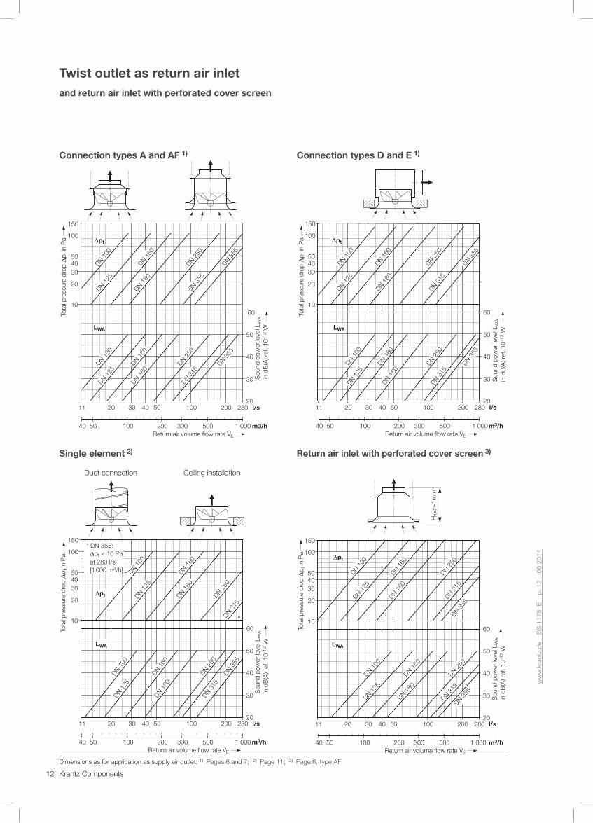
Twist outlet as return air inletand return air inlet with perforated cover screen
Connection types A and AF 1)
40 50 100 200 300 500 1 000
150
100
504030
20
1060
50
40
30
20
pt
LWA
DN 100
DN 125
DN 160
DN 250
DN 355
DN 180
DN 315
DN 100
DN 160
DN 250
DN 355
DN 125
DN 180
DN 315
Sou
nd p
ower
leve
l LW
A
in d
B(A
) ref
. 10-
12 W
200 2801005040302011
Tota
l pre
ssur
e dr
op
p t in
Pa
Return air volume flow rate V·E
m3/h
l/s
Single element 2)
Duct connection Ceiling installation
150
100
504030
20
1060
50
40
30
20
*
pt
LWA
DN 100
DN 160
DN 125
DN 180
DN 315
DN 250
DN 100
DN 125
DN 180
DN 160
DN 250
DN 355
DN 315
40 50 100 200 300 500 1 000Return air volume flow rate V·E
Tota
l pre
ssur
e dr
op
p t in
Pa
Sou
nd p
ower
leve
l LW
A
in d
B(A
) ref
. 10-
12 W
200 2801005040302011
m3/h
l/s
* DN 355: pt < 10 Pa at 280 l/s [1 000 m3/h]
Connection types D and E 1)
150
100
504030
20
1060
50
40
30
20
pt
DN 100
DN 125
DN 160
DN 250
DN 355
DN 180
DN 315
LWA
DN 100
DN 160
DN 125
DN 250
DN 355
DN 180
DN 315
40 50 100 200 300 500 1 000Return air volume flow rate V·E
Sou
nd p
ower
leve
l LW
A
in d
B(A
) ref
. 10-
12 W
Tota
l pre
ssur
e dr
op
p t in
Pa
200 2801005040302011
m3/h
l/s
Return air inlet with perforated cover screen 3)
H1A
F+1m
m
40 50 100 200 300 500 1 000Return air volume flow rate V·E
150
100
504030
20
1060
50
40
30
20
pt
DN 100
DN 125
DN 160
DN 180
DN 250
DN 315
DN 355
LWA
DN 100
DN 125
DN 160
DN 250
DN 180
DN 315
DN 355
Sou
nd p
ower
leve
l LW
A
in d
B(A
) ref
. 10-
12 W
Tota
l pre
ssur
e dr
op
p t in
Pa
200 2801005040302011
m3/h
l/s
Dimensions as for application as supply air outlet: 1) Pages 6 and 7; 2) Page 11; 3) Page 6, type AF

13Krantz Components
ww
w.k
rant
z.de
D
S 1
175
E
p. 1
2
06.2
014
ww
w.k
rant
z.de
D
S 1
175
E
p. 1
3
06.2
014
Twist outlet
Type code – as supply air outlet
DD-N _ – DN ___ – __ __ __ – __ – ___ – _
Twis
t out
let
––––
––––
Mat
eria
l ––
––––
––––
– S
ize
–––
––––
––––
–––
Con
nect
ion
type
–––
– D
ampe
r –
––––
––––
–– In
sula
tion
–––
––––
–––
Pai
ntin
g –
––––
––––
–– S
urfa
ce fi
nish
––
––––
Acc
esso
ries
––––
––––
MaterialK = Plastic A = Aluminium
Size
Plastic Aluminium
63 = DN 63 •
100 = DN 100 •
125 = DN 125 •
160 = DN 160 •
180 = DN 180 •
250 = DN 250 • •
315 = DN 315 • •
355 = DN 355 •
Connection type O = no connection piece (only discharge element) A = reducer (connection type A) AF = reducer with support flange (connection type AF) D = connection box (connection type D), external sleeve E = connection box (connection type E), outlet flush with connection box L = perforated hood 2)
DamperO = no volume flow damper R = with volume flow damper adjustable from room S = with volume flow damper adjustable at spigot 1)
InsulationO = without acoustic lining I = with acoustic lining
Painting P = powder-coated (for the aluminium type) N = wet painted (for the plastic type) E = body tinted (only for the plastic type)
Surface finish 9010 = face painted to RAL 9010, semi-matt 7038 = face painted to RAL 7038, semi-matt …. = face painted to RAL …
Accessories O = none L = perforated cover
– as return air inlet
DA-L – DN ___ – ___
Ret
urn
air
inle
t ––
––––
Siz
e –
––––
––––
––––
– S
urfa
ce fi
nish
––
––––
Size: 100 = DN 100 125 = DN 125 160 = DN 160 180 = DN 180 250 = DN 250 315 = DN 315 355 = DN 355
Surface finish 9010 = face painted to RAL 9010, semi-matt 7038 = face painted to RAL 7038, semi-matt …. = face painted to RAL …
1) Available for connection box of type E2) Perforated hood for supply air to increase pressure upon request

14 Krantz Components
Tender text – Supply air outlet
... units – Twist outlet with high induction e�ect for di�use air �ow in room at minimum temperature gradients in the occupied zone,
consisting of:– twist outlet element with spigot, circular face and twist vanes,
optionally �tted with perforated cover screen for visually plane ceiling surface,duct connection via reducer with lateral L-suspensions or reducer with support �ange for placement on false ceiling and with lateral L-suspensions, each type of reducer with central fastener for air outlet, or connection via �at connection box with connection spigot and central fastener for air outlet, including �ange bores for suspension, with optional volume �ow damper adjustable from room or – for connection type E – adjustable at spigot, box optionally �tted with acoustic lining.
Material:– Twist outlet element made of polystyrene, body-tinted to
RAL 7038, agate grey, or wet painted to RAL 9010, pure white 2)
– Twist outlet element made of aluminium in natural colour or powder-coated to RAL 9010, pure white 2 + 3)
– Perforated cover screen made of aluminium, powder-coated to RAL 9010, pure white 2)
– Reducer made of aluminium– Reducer made of aluminium with support �ange– Connection box made of galvanized sheet metal
Make : Krantz ComponentsType: DD-N _ – DN ___ – __ __ __ – __ – ___ – _
– Return air inlet with perforated cover screen 1)
... units – Return air inlet with perforated cover screen
consisting of:– perforated cover screen with circular face, reducer with �ange
and lateral L-suspensions, including central fastener for per-forated cover screen.
Material:– Perforated cover screen made of aluminium, powder-coated to
RAL 9010, pure white– Reducer made of aluminium with support �ange
Make : Krantz ComponentsType: DA-L – DN ___ – ___
Subject to technical alterations.
1) Applies for return air inlet with perforated cover screen, see page 12.Where supply air outlets are used as return air inlets, the tender textis the same as for supply air outlets.
2) Other colours on request3) Only sizes DN 250, DN 315 and DN 355 available
ww
w.k
rant
z.de
D
S 11
75 E
p
. 14
06
.201
4
Twist outlet
Distributore in esclusiva per l’Italia:
F.C.R. Filtrazione Condizionamento Riscaldamento SpAVia E. Fermi, 3 - 20092 Cinisello Balsamo (MI) - Italyphone +39 02 61798 1 - fax +39 02 61798 300www.fcr.it - [email protected]