TurboDraft Operating · PDF fileFI R E E D UCTOR by Schutte & Ko erting Operating...
24
F I R E E D U C T O R by Schutte & Koerting Operating Instructions www.turbodraft.net 2510 Metropolitan Drive • Trevose, PA 19053 • tel: (215)639-0900 • fax: (215)639-1597 • [email protected] TurboDraft ™ Fire Eductor Operating Instructions www.turbodraft.net
Transcript of TurboDraft Operating · PDF fileFI R E E D UCTOR by Schutte & Ko erting Operating...

F I R E E D U C T O R
by Schutte & Koerting
Operating Instructionswww.turbodraft.net
2510 Metropolitan Drive • Trevose, PA 19053 • tel: (215)639-0900 • fax: (215)639-1597 • [email protected]
TurboDraft™
Fire Eductor
OperatingInstructions
www.turbodraft.net

1234djfkjldfjlkdjfklsdjlkjfdslkjfsd

F I R E E D U C T O R
by Schutte & Koerting
Operating Instructionswww.turbodraft.net
2510 Metropolitan Drive • Trevose, PA 19053 • tel: (215)639-0900 • fax: (215)639-1597 • [email protected]
Table of Contents
Description Page
Introduction……..………………………..........……............. 1
Safety Guidelines……………………………....................... 2
Care and Maintenance………………………...................... 3
TurboDraft Set-Up……………………………...................... 4 - 6
Tandem TurboDraft Operations……………....................... 7
Strainer Clearing………………………………..................... 8
Operating Tips…………………………………..................... 9 - 10
Unit Testing……………………………………...................... 11
Using the Distant Water Source Table……....................... 12
Unit Specifications……………………………...................... 13
2-1/2” TurboDraft Operating Instructions…....................... 14
Notes (Intentionally Blank)…………………....................... 15 - 20

F I R E E D U C T O R
by Schutte & Koerting
12510 Metropolitan Drive • Trevose, PA 19053 • tel: (215)639-0900 • fax: (215)639-1597 • [email protected]
Operating Instructionswww.turbodraft.net
Fire EductorsFor many years Schutte & Koerting has provided portable eductors to the U.S. Navy.These eductors were used for fire fighting onboard ships. The units were used toincrease the volume of water available for fire fighting. They utilized the high pressurepumps onboard to supply the motive flow to the eductor which was placed overboard.The design of the unit was for high discharge head and typically had a two-to-one flowratio. (i.e. 100 gpm of motive, 200 gpm of suction, with total flow of 300 gpm.)
Over the past several years, Schutte & Koerting has worked with several local firefighters to develop an eductor designed to be used for rural water supply operations.Many of us take for granted that there is a fire hydrant on every corner. Unfortunately,this is not the case. A large percentage of the fire companies outside large citiesdepend on lakes, ponds, streams, rivers, and even swimming pools as a water sourceduring a fire. Water is currently accessed from these sources in two ways. The firstchoice is to maneuver the fire truck close (typically 30 feet or less) to the water sourceand use the onboard pump to draft. This produces the greatest water flow. In manycases, this is not possible due to weather or access restrictions. The second option isto carry a large portable pump to the water source and use this to draft the water anddischarge it back to a pumper truck or portable tank close to and accessible to the firetrucks. Portable pumps large enough to supply sufficient water flows tend to be largeand require routine maintenance.
Schutte & Koerting has developed an eductor to utilize the third option for water supply.Our eductor utilizes the water stored onboard the fire truck as the motive flow to startthe eductor flow and return the motive flow as well as the suction flow back to the firetruck. This allows the fire truck to be at least 150 feet away from the water and stillachieve significant net water flow to be utilized for fire fighting.
To put the unit in operation, a 21⁄2 inch hose line and a 5 inch LDH supply line arestretched from the fire truck with the eductor to the water supply. The eductor is placedin the water and the motive line is charged to 150 psig. This immediately starts the flowof water back to the fire truck through the 5 inch LDH supply line. Once the suction flowis established, the first portion of the flow is used to replenish the tank water in the truck.Once the tank has been replenished, the water supply has been established and watercan be supplied for use on the fire. The unit was designed for 17.5 feet of head andduring our prototype testing we were able to achieve 750 gpm net suction gain. Wesupplied 200 gpm at 150 psig to the eductor, 750 gpm was developed as a suction flowwith a total flow back to the fire truck of 950 gpm. 200 gpm of the 950 gpm was beingrecycled back to supply the eductor.
Testing was completed in the Spring of 2000 and marketing began in early Autumn ofthat same year.
F I R E E D U C T O R
by Schutte & Koerting
Operating Instructionswww.turbodraft.net
22510 Metropolitan Drive • Trevose, PA 19053 • tel: (215)639-0900 • fax: (215)639-1597 • [email protected]
Safety Guidelines1. Carefully read and follow all operating instructions before putting the
TurboDraft unit into service.
2. Be sure all pump operators are properly trained in the correct and safe useof the fire pump that is supplying the TurboDraft unit.
3. Proper personal protective equipment should be utilized while operatingany fire pump and while present at any emergency scene.
4. Be sure all hose connections are snug and secure.
5. Use caution at all times around any high pressure pump connections.
6. Always understand and follow all department rules, guideline andoperating procedures.

F I R E E D U C T O R
by Schutte & Koerting
32510 Metropolitan Drive • Trevose, PA 19053 • tel: (215)639-0900 • fax: (215)639-1597 • [email protected]
Operating Instructionswww.turbodraft.net
Care and MaintenanceThe TurboDraft unit is manufactured from aluminum and stainless steel. Littlemaintenance is required to keep your TurboDraft unit in proper operatingcondition.
1. Before and after using the TurboDraft, carefully inspect the unit for any damageto the body, tail, and fire connections.
2. After use, flush the unit with clean water to remove any mud, sand or debrisfrom the inside and outside surfaces. Be sure to thoroughly flush the 21⁄2 inchconnection, as any sand or grit will effect the swivel action. Also, inspect thatthe screen is free from any obstructions (grass, leaves, etc.). Mild soap and asoft brush should remove any dried mud or soils from the unit.
3. IMPORTANT - Inspect nozzle orifice to be sure there are no obstructions. Anyrestrictions within the nozzle will dramatically effect the performance of theTurboDraft unit.
4. Safely store the unit securely on or in the apparatus to avoid injury to personneland damage to the TurboDraft.

F I R E E D U C T O R
by Schutte & Koerting
Operating Instructionswww.turbodraft.net
42510 Metropolitan Drive • Trevose, PA 19053 • tel: (215)639-0900 • fax: (215)639-1597 • [email protected]
TurboDraft Setup/Operation• The unit requires a 21⁄2 inch discharge line from the fire truck and a 5 inch supply line
to return water flow to the fire pump.
• The lines should be stretched from the truck to the water’s edge avoiding sharpbends and kinks.
• Before connecting hoses to the TurboDraft, inspect the unit to be sure no debris hasentered the inlet or discharge openings.
• Connect the 21⁄2 inch line to a discharge from the pump and to the TurboDraft unit,as shown below.
• Connect a 5 inch LDH supply line to pump intake valve and TurboDraft unit, asshown below.
• Care should be taken to insure all connections are tight and secure. A rope orwebbing may be attached to the handle and secured, however, this is not criticalbecause the unit may be retrieved using the hose lines.
• Submerge in 2 to 3 feet of standing water, with the screen/strainer facing up, 1 to 11⁄2feet of moving water.
• After the above steps are complete the unit is ready to be put into operation.

F I R E E D U C T O R
by Schutte & Koerting
52510 Metropolitan Drive • Trevose, PA 19053 • tel: (215)639-0900 • fax: (215)639-1597 • [email protected]
Operating Instructionswww.turbodraft.net
TurboDraft Set-Up/Operation• Engine should be placed into pump gear
and truck prepared for pumpingoperations.
• The intake valve should be closed.
• Open the bleeder on the suction intakevalve to allow any air in the hose to bevented.
• Open the tank-to-pump valve.
• Increase the engine pressure to 175PSIG.
• Open the 21⁄2 inch discharge supplying theTurboDraft unit and maintain dischargepressure at 175 PSIG. This is required tostart suction flow back to the truck.
• As the 21⁄2 inch line is charged, the 5 inchline will immediately start to fill.
• Close the bleeder once water reaches itand slowly open the suction intake valve.
• The water supply is now established.
F I R E E D U C T O R
by Schutte & Koerting
Operating Instructionswww.turbodraft.net
62510 Metropolitan Drive • Trevose, PA 19053 • tel: (215)639-0900 • fax: (215)639-1597 • [email protected]
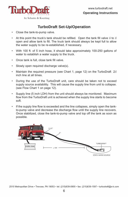
TurboDraft Set-Up/Operation• Close the tank-to-pump valve.
• At this point the truck’s tank should be refilled. Open the tank fill valve 1⁄4 to 1⁄2open and allow tank to fill. The truck tank should always be kept full to allowthe water supply to be re-established, if necessary.
• With 100 ft. of 5 inch hose, it should take approximately 100-250 gallons ofwater to establish a water supply to the truck.
• Once tank is full, close tank fill valve.
• Slowly open required discharge valve(s).
• Maintain the required pressure (see Chart 1, page 12) on the TurboDraft 21⁄2inch line at all times.
• During the use of the TurboDraft unit, care should be taken not to exceedsupply source availability. This will cause the supply line from unit to collapse.(see Flow Chart 1 on page 12).
• Supply line (5 inch LDH) from the unit should always be monitored. Maximumflow from the TurboDraft unit is achieved when the supply line starts to becomesoft.
• If the supply line flow is exceeded and the line collapses, simply open the tank-to-pump valve and decrease the discharge flow until the supply line recovers.Once stabilized, close the tank-to-pump valve and top off the tank as soon aspossible.
2-1/2"
5"
± 100'
TURBODRAFT
STATIC WATER SOURCE
PORTA-TANK
F I R E E D U C T O R
by Schutte & Koerting
72510 Metropolitan Drive • Trevose, PA 19053 • tel: (215)639-0900 • fax: (215)639-1597 • [email protected]
Operating Instructionswww.turbodraft.net
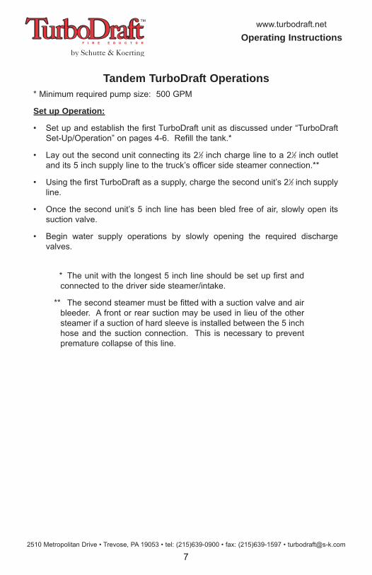
Tandem TurboDraft Operations* Minimum required pump size: 500 GPM
Set up Operation:
• Set up and establish the first TurboDraft unit as discussed under “TurboDraftSet-Up/Operation” on pages 4-6. Refill the tank.*
• Lay out the second unit connecting its 21⁄2 inch charge line to a 21⁄2 inch outletand its 5 inch supply line to the truck’s officer side steamer connection.**
• Using the first TurboDraft as a supply, charge the second unit’s 21⁄2 inch supplyline.
• Once the second unit’s 5 inch line has been bled free of air, slowly open itssuction valve.
• Begin water supply operations by slowly opening the required dischargevalves.
* The unit with the longest 5 inch line should be set up first andconnected to the driver side steamer/intake.
** The second steamer must be fitted with a suction valve and airbleeder. A front or rear suction may be used in lieu of the othersteamer if a suction of hard sleeve is installed between the 5 inchhose and the suction connection. This is necessary to preventpremature collapse of this line.

F I R E E D U C T O R
by Schutte & Koerting
Operating Instructionswww.turbodraft.net
82510 Metropolitan Drive • Trevose, PA 19053 • tel: (215)639-0900 • fax: (215)639-1597 • [email protected]
Strainer ClearingDuring operation of the unit it may become necessary to clear the strainer of grass ordebris from the water source. This is easily performed and should only take 15 to 30seconds.
• Discontinue water supply operationsby closing down all discharges fromthe truck except for the line supplyingthe TurboDraft unit.
• Open the tank-to-pump valve.
• Slowly close the suction intake valve.This will cause the flow of water tobackup into the strainer and clear anyobstructions from the screen.
• Keep valve closed for 15 to 30seconds to ensure the debris iscleared from the strainer area.
• Slowly open the suction intake valveto re-establish the water supply.
• Close tank-to-pump valve and opentank fill valve 1⁄4 to 1⁄2 and refill tank.
• When tank is full, close tank fill valveand resume flow operations.
5” SUPPLY LINE2.5” DISCHARGELINE
DISCHARGE 5”STORTZ
SUCTION FLOW
2.5”
NST
CO
NN
ECTI
ON
FIGURE 1
(NOTE:UNIT ISSUBMERGEDIN WATERSUPPLY)
MO
TIVE
arrow indicatesback flow to clearthe screen
F I R E E D U C T O R
by Schutte & Koerting
92510 Metropolitan Drive • Trevose, PA 19053 • tel: (215)639-0900 • fax: (215)639-1597 • [email protected]
Operating Instructionswww.turbodraft.net
Operating Tips• Maintain pump seals per manufacturer’s recommendations and tightly close all
valves and bleeders to prevent air leaks and loss of prime.
• Take care to keep discharge flow rates within TurboDraft’s rated capacity (seeChart 1 on page 12). If you do not, the suction hose will collapse.
NOTE Keep hose lays and lifts as short as possible.The shorter the hose and lift, the greater your flow.
• The supply line (or longest supply line if two units are being used) should beconnected to the driver side pump panel. This allows the driver to feel andsee the hose. The TurboDraft’s maximum flow is achieved when the supplyhose starts to become soft.
• If the supply hose does collapse, quickly open the tank-to-pump valve toreestablish flow. Then, reduce discharge flow to within units’ capability and topoff tank.
NOTE When operating near capacity or under fluctuating discharge conditions, be ready by keeping your hand on the tank-to-pump valve.
• If the TurboDraft cannot be adequately submerged, use tennis balls (or otherfloating object) or a booster line sprayed above its inlet to break the vortex andprevent air from getting into the pump (i.e., loss of prime).

F I R E E D U C T O R
by Schutte & Koerting
Operating Instructionswww.turbodraft.net
102510 Metropolitan Drive • Trevose, PA 19053 • tel: (215)639-0900 • fax: (215)639-1597 • [email protected]
Operating Tips• Under heavy algae surface debris conditions, back flushing (shown on page 8)
may not be sufficient to prevent clogging of the strainer. Use a booster orforestry line to keep as much algae away as possible.
• If you have a pressure governor, use it. This will help maintain the constantdischarge pressure required to the unit.
• TurboDraft use should be regularly practiced and results confirmed individuallyas this may vary slightly between trucks and operators.
• The pump’s rated capacity at 150 psi should exceed the expected flow rate(see Chart 1 on page 12) by 300 GPM. The TurboDraft unit cannot achievemaximum rated flows with pumpers having rated capacities of less than 1,000GPM.

F I R E E D U C T O R
by Schutte & Koerting
112510 Metropolitan Drive • Trevose, PA 19053 • tel: (215)639-0900 • fax: (215)639-1597 • [email protected]
Operating Instructionswww.turbodraft.net
Unit Testing• A simple test can be performed to
determine the fire flow of a given watersource.
• In addition to the TurboDraft setup, connecta master stream device with a straightbore nozzle.
• See page 12 to determine the estimatedfire flow for your location and requirednozzle bore for deck gun.
• Place the TurboDraft unit in operation asshown on pages 4 through 6.
• Once the water supply is established, startflowing water to the deck gun and continueto increase water flow to the deck gun untilthe 5 inch line from the TurboDraft starts toget soft. At this point you have reached themaximum flow.
• Read the pressure at the deck gun. Referto Chart 3 below to determine the flow forthe deck gun at that pressure.
GPM At Various Pressures (PSIG)Nozz.Dia. 30 35 40 45 50 55 60 66 70 76 80 85 90 95 100 105 110 115 120
11⁄8” 206 222 238 252 266 279 291 305 315 328 336 347 357 366 376 385 394 403 412
13⁄8” 308 332 355 377 397 417 435 456 470 490 502 518 533 547 562 575 589 602 615
11⁄2” 366 395 423 448 473 496 518 543 559 583 598 616 634 651 668 685 701 717 732
Chart 3

F I R E E D U C T O R
by Schutte & Koerting
Operating Instructionswww.turbodraft.net
122510 Metropolitan Drive • Trevose, PA 19053 • tel: (215)639-0900 • fax: (215)639-1597 • [email protected]
Using The Distant Water Source Table
Lengthof 5”Hose
Lift PumpDischargePressure
Max. Avail.
Fire Flow
50’10’ 175 psig 670 GPM20’ 175 psig 470 GPM
100’10’ 180 psig 570 GPM20’ 180 psig 400 GPM
150’10’ 185 psig 480 GPM20’ 185 psig 325 GPM
200’10’ 190 psig 440 GPM20’ 190 psig 280 GPM
Chart 1
1. Determine the required hose length (use the longer of the two if two TurboDraft unitswill be used). Refer to Chart 2 below for friction loss in hose line.
2. Estimate or measure the required lift. This is best done by pre-planning watersource and actual measurement is preferred, as lifts can be visually deceiving.
Hint: Place a pressure gauge on the end of a hose line. Place the gaugeat water’s edge and the opposite end of hose at truck elevation. Fill hosewith water leaving the truck end open to atmosphere. The lift can beestimated by multiplying the pressure gauge reading (psi) by 2.3.
3. Read across and determine the required discharge pressure for the TurboDraft’s 21⁄2inch line and the maximum available fire flow.
Friction Loss / 100 Ft. Of 5” HoseGPM 400 500 600 700 800 900 1000 1200PSI 1.1 1.7 2.4 3.3 4.2 5.3 6.5 9.3
Chart 2

F I R E E D U C T O R
by Schutte & Koerting
132510 Metropolitan Drive • Trevose, PA 19053 • tel: (215)639-0900 • fax: (215)639-1597 • [email protected]
Operating Instructionswww.turbodraft.net
Specifications
9
10
213 14
17
12 5/16
8 5/16
5 11/16
4 1/
2
8 9/
16 11 7
/8
3
4
8 119
12
2
57
11 3/16 24 5/8
5/8
38 3/4
16
MK NO DESCRIPTION QTY MATERIAL REMARKS01 FIRE EDUCTOR ASSY. 1 ALUMINUM02 BODY 1 ALUMINUM 99EB123J00203 NOZZLE 1 ALUMINUM 131J0113J00104 TAIL 1 ALUMINUM 98GB137J00205 INLET PIPE 1 ALUMINUM 0010166J00106 FILTER SCREEN 1 SST TY 304 0010115J00107 BOLTING PLATE 2 ALUMINUM 0410098J00108 HEX HEAD CAP SCREW 8 18-8 SST 0510220J00109 5” FIRE HOSE ADAPTER 1 ALUMINUM 001B201J00110 2-1/2” FIRE HOSE ADAPTER 1 ALUMINUM 98S0360J00111 RIVET 8 SST TY 303 TD500-RIVET12 HEX HEAD CAP SCREW 2 18-8 SST AAA29D2213213 NAME PLATE 1 ALUMINUM 0010196J00114 DRIVE SCREWS 4 0 - 1/8, 18-8 SST 0010197J00115 I.O. & M. MANUAL 1 0010244J001
16EYEBOLT WITH LOCKNUT 1 SS
091J0228001091J0229001
17 HANDLE 1 SST A351 CF8M 0110195J001
Distant Water Source Situation 1,2,3
Length of 5” Hose Lift
PumpDischargePressure
Max. Avail. Fire Flow 1,2
50’10’ 175 psig 670 GPM20’ 175 psig 470 GPM
100’10’ 180 psig 570 GPM20’ 180 psig 400 GPM
150’10’ 185 psig 480 GPM20’ 185 psig 325 GPM
200’10’ 190 psig 440 GPM20’ 190 psig 280 GPM
Note: Using 6” supply line can increase unitoutput by decreasing line friction losses.
1 Theoretical, based on test curves of 9/21/99 andhose friction loss per NFPA® Fire ProtectionHandbook, 15th Edition, Table 17-7H, actual frictionlosses may vary depending upon hose and couplingdesign/manufacturer.
2 All flows achievable with 1,000 GPM rated pumperbased on NFPA recommended pump curves. Uselarger pumper where maintenance/performance isquestionable.
3 Minimum available flow from water sourcerecognized by ISO for grading purposes is 250 GPM.ISO does not recognize drafting sources requiring alift in excess of 18’ (This is not a drafting device as itoperates under pressure.)
Net weight of unit: 48.5 lbs.

F I R E E D U C T O R
by Schutte & Koerting
Operating Instructionswww.turbodraft.net
142510 Metropolitan Drive • Trevose, PA 19053 • tel: (215)639-0900 • fax: (215)639-1597 • [email protected]
2-1/2” TurboDraft – Operating InstructionsTurboDraft Operation
Once the TurboDraft Fire Eductor has been set up itcan be quickly placed into service. The steamersuction valve is left closed and its air bleeder isopened. The 11⁄2 inch line is charged to approximately175 psig. The force of the flow combined withTurboDraft eductor technology creates a suctionwhich draws water from the standing water supply. Asthis happens, the return line is charged back to the firetruck. Once the air is bled from the supply line, thebleeder is closed and the steamer valve is opened. Atthis point the water supply has been established. 60GPM is re-circulated through the truck to maintain acontinuous flow and 264 GPM is available to supplytanker trucks or fill portable tanks. Useable fire flowwill vary based on elevation and hose friction loss.(See table below.)
Tap Water Sources in Remote Locations
Rural fire companies need creative solutions to utilizewater sources that are not accessible using typicaldrafting techniques. Schutte & Koerting’s TurboDraftFire Eductor allows fire companies to tap into watersupplies like ponds, streams, and swimming pools upto 250’ away and can generate flows up to 264 GPM.
150 PSIG Supply Pressu
165 PSIG Supply Pressu
180 PSIG Supply Pressu
10
20
30
0 50 100 150 200 250 300
Net Suction Flow (GPM)
2 1/2” TurboDraft Fire EductorPerformance
Supply flow is 60 gpm psig truck pressure
Dis
char
ge H
ead
(ft)
Distant Water Source Situation for 21⁄2” Unit
Length of 21⁄2” Hose
LiftPump
DischargePressure
Max. Avail.
Fire Flow
50’10’ 175 psig 264 GPM20’ 175 psig 185 GPM
100’10’ 180 psig 224 GPM20’ 180 psig 157 GPM
150’10’ 185 psig 189 GPM20’ 185 psig 128 GPM
200’10’ 190 psig 173 GPM20’ 190 psig 110 GPM
Overall Length: 30”Weight: 20 lbs.Connections: 11⁄2” NST Female Inlet
21⁄2” NST Male Outlet

F I R E E D U C T O R
by Schutte & Koerting
152510 Metropolitan Drive • Trevose, PA 19053 • tel: (215)639-0900 • fax: (215)639-1597 • [email protected]
Operating Instructionswww.turbodraft.net
Notes

F I R E E D U C T O R
by Schutte & Koerting
Operating Instructionswww.turbodraft.net
162510 Metropolitan Drive • Trevose, PA 19053 • tel: (215)639-0900 • fax: (215)639-1597 • [email protected]
Notes

F I R E E D U C T O R
by Schutte & Koerting
172510 Metropolitan Drive • Trevose, PA 19053 • tel: (215)639-0900 • fax: (215)639-1597 • [email protected]
Operating Instructionswww.turbodraft.net
Notes

F I R E E D U C T O R
by Schutte & Koerting
Operating Instructionswww.turbodraft.net
182510 Metropolitan Drive • Trevose, PA 19053 • tel: (215)639-0900 • fax: (215)639-1597 • [email protected]
Notes

F I R E E D U C T O R
by Schutte & Koerting
192510 Metropolitan Drive • Trevose, PA 19053 • tel: (215)639-0900 • fax: (215)639-1597 • [email protected]
Operating Instructionswww.turbodraft.net
Notes

F I R E E D U C T O R
by Schutte & Koerting
Operating Instructionswww.turbodraft.net
202510 Metropolitan Drive • Trevose, PA 19053 • tel: (215)639-0900 • fax: (215)639-1597 • [email protected]
Notes

030314