Turbine Inlet Chilling & Generation Storage® Best Practices · AGENDA • TAS Introduction •...
38
Turbine Inlet Chilling & Generation Storage® Best Practices 8 Oct 14 Trey Sims Turnkey Sales Manager
-
Upload
vuongkhanh -
Category
Documents
-
view
213 -
download
0
Transcript of Turbine Inlet Chilling & Generation Storage® Best Practices · AGENDA • TAS Introduction •...

Turbine Inlet Chilling & Generation Storage®
Best Practices
8 Oct 14
Trey Sims
Turnkey Sales Manager
INTRODUCTIONS
© 2012 TAS Energy. All Rights Reserved. 2
Dharam Punwani
• President
Avalon Consulting, Inc.
• Executive Director, TICA
Trey Sims
• Turnkey Sales Manager
• TAS Energy

AGENDA
• TAS Introduction
• Technology Overview – Generation Storage & Inlet Chilling
• Project Examples
• Best Practices
• Questions
© 2012 TAS Energy. All Rights Reserved. 3

COMPANY INTRODUCTION
© 2012 TAS Energy. All Rights Reserved. 4
CORE COMPETENCIES

COMPANY HISTORY
© 2012 TAS Energy. All Rights Reserved. 5
2005
TAS provides TIC system for GE’s most
advanced 7H CC gas turbine plant
2005 TAS is chosen to build
the world’s largest District Cooling plant at Crescent of Palm Island
in Dubai
1980s
Tom Pierson leads the team that developed the first gas turbine
inlet air-cooling systems
1999
TAS manufacturers first modular Turbine Inlet
Chilling (TIC) unit
1980s 1999 2009 2005 2011 2001 2003 2007
1999 TAS Energy
Founded by Tom Pierson
2009 TAS Energy sells
its first geothermal plant
2005 TAS completes first
turnkey TIC retrofit in Asia
2001 TAS provides over
100,000 TR of chilling
2008 TAS sells first
domestic turnkey retrofit
for 2x7FA CC plant
2011 TAS Energy sells largest
Generation Storage™ project in North America
and Nears 1M TR of total chilling
2002 TAS Energy begins to focus on large-scale
chilling plants for commercial buildings
2008
TAS Energy expands its offerings in the Mission Critical
markets

MANUFACTURING FACILITY
• Houston, TX HQ
• 275,000 sq ft
• 80 Ton Crane Capacity
• In-house pneumatic testing – Pressure & Leak Testing
© 2012 TAS Energy. All Rights Reserved. 6

GLOBAL PRESENCE
© 2012 TAS Energy. All Rights Reserved. 7
Technology Overview

© 2013 TAS Energy. All Rights Reserved.
Turbine Inlet Chilling (TIC) & Generation Storage (GS)
• Gas turbines only operate at 100% of their rated capacity when the temperature outside is 59F.
Inlet Air Temperature, degrees (F)
GT POWER OUTPUT
80%
85%
90%
95%
100%
105%
110%
40 45 50 55 60 65 70 75 80 85
% o
f R
ate
d C
ap
acit
y
RECOVERED POWER
ADDITIONAL POWER
• By chilling below rated capacity and adding storage
TAS Generation Storage
95 100 90
• As temperatures climb into the 90’s and beyond, greater than 10% of the capacity of the turbine disappears.
RATED CAPACITY
all lost power is recovered, and additional power is
generated. • Storage and ancillary services including ramping benefits are captured as well

WATER-COOLED MECHANICAL
© 2012 TAS Energy. All Rights Reserved. 10
Compressor Turbine
Ambient Air
Power (kW)
Cool Air
Cooling Tower
Heat Rejection via
Evaporation
Make-Up Water
Condenser
Evaporator
Chiller
Expansion Valve
Compressor
Coil Condensate
Coils
Generator

GS: More Than Just Capacity
© 2012 TAS Energy. All Rights Reserved.
CHILLER PLANT
SECONDARY PUMP
PR
IMA
RY
PU
MP
START CHILLER
STOP CHILLER
BURN CYCLE BUILD CYCLE
TES TANK
UPPER DIFFUSER
LOWER DIFFUSER
GTG
START PUMP
STOP PUMP
11
Simply adjust the pump for
the full range of power
according to grid need-
under four min response,
no heavy maintenance
impact

Generation Storage - PFD
© 2012 TAS Energy. All Rights Reserved.
TES Tank
Combustion Turbine “2”
Partial Storage Full Storage
Combustion Turbine “1”
Combustion Turbine “3”
Secondary Pump Skid
12 © 2012 TAS Energy. All Rights Reserved.

PFD – CHARGE 12/10/2
© 2012 TAS Energy. All Rights Reserved.
TES Tank
Combustion Turbine “2”
Partial Storage Full Storage
Combustion Turbine “1”
Combustion Turbine “3”
Secondary Pump Skid
13 © 2012 TAS Energy. All Rights Reserved.
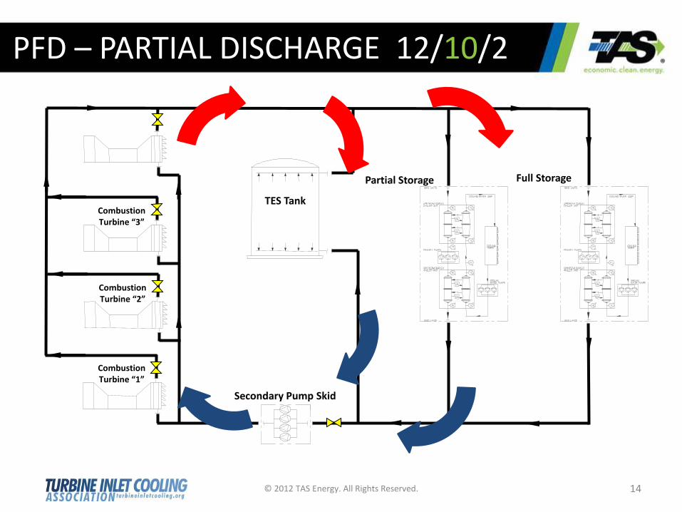
PFD – PARTIAL DISCHARGE 12/10/2
© 2012 TAS Energy. All Rights Reserved.
TES Tank
Combustion Turbine “2”
Partial Storage Full Storage
Combustion Turbine “1”
Combustion Turbine “3”
Secondary Pump Skid
14

PFD – FULL DISCHARGE 12/10/2
© 2012 TAS Energy. All Rights Reserved.
TES Tank
Combustion Turbine “2”
Partial Storage Full Storage
Combustion Turbine “1”
Combustion Turbine “3”
Secondary Pump Skid
15
SuperPeakTM

F-SKID FEATURES
© 2012 TAS Energy. All Rights Reserved. 16
Chiller Skid #2
Chiller Skid #1
Pump/Dry Room Skid
Chiller Bundle Maintenance
Areas
Skid Splits

F-SKID FEATURES
© 2012 TAS Energy. All Rights Reserved. 17
Three Skid Arrangement
Chiller Room
Cooling Tower Access
Pump/Dry Room Skid Split

TES TANK CONSTRUCTION
© 2012 TAS Energy. All Rights Reserved. 18

TES TANK CONSTRUCTION
© 2012 TAS Energy. All Rights Reserved.
Pre-Stressing Calibrated Wire Spacing
19

TES TANK INTERNALS
© 2012 TAS Energy. All Rights Reserved.
Lower Diffuser Manifold Upper Diffuser
Manifold
Diffuser Holes
20

TYPICAL LAYOUT
© 2012 TAS Energy. All Rights Reserved. 21
TES Tank
Chiller
Package
Coil
Retrofit
Secondary
Pump Skid

PROJECT PROFILE
© 2012 TAS Energy. All Rights Reserved. 22
Project Timing: 2008-2009 Outage Duration: ~15-30 Days Construction Man-Hours: ~50,000 Construction Duration: ~9 Months Project Timing: 2008-2009

PROJECT PROFILE
© 2012 TAS Energy. All Rights Reserved. 23

PROJECT PROFILE
TES Tank
Chiller
Package
Coil
Retrofit
Secondary
Pump Skid
• 48 MW increase

PROJECT PROFILE
© 2012 TAS Energy. All Rights Reserved. 25
• 53.4 MW increase

PROJECT PROFILE
© 2012 TAS Energy. All Rights Reserved. 26
TANK SIZE: 7.6 MG POWER INCREASE: 115 MW Near Trenton, NJ

© 2012 TAS Energy. All Rights Reserved. 27
PROJECT PROFILE
TANK SIZE: 3.9 MG POWER INCREASE: 60 MW
© 2012 TAS Energy. All Rights Reserved. 28
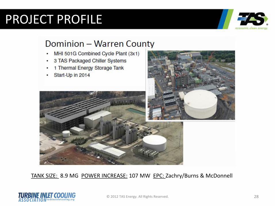
PROJECT PROFILE
TANK SIZE: 8.9 MG POWER INCREASE: 107 MW EPC: Zachry/Burns & McDonnell

© 2012 TAS Energy. All Rights Reserved. 29
PROJECT PROFILE
TANK SIZE: 10.7 MG POWER INCREASE: 123 MW EPC: Fluor

Turbine Inlet Chilling (TIC) Generation Storage Best Practices

DESIGNING THE SYSTEM
WHAT IS THE DRIVER FOR ADDITIONAL CAPACITY?
• Do you need the added capacity 24 hours per day
• How many hours do you want highest output
• What are revenue considerations – How valuable is another 5-7 MW on top of system addition
• Will there be an expansion effort onsite in future
• Availability of water
© 2012 TAS Energy. All Rights Reserved. 31

AF COIL MODULE DESIGN
© 2012 TAS Energy. All Rights Reserved. 32

CONCENTRIC VS. ECCENTRIC
© 2012 TAS Energy. All Rights Reserved.
• Eccentric Inlet Duct • Extended Inlet Duct for Fogging
BEFORE
• Concentric Inlet Duct • New Spacer Elevates Inlet Duct • Existing Filter House Utilized
AFTER
33

BEST PRACTICTES
WINTERIZATION
• No Glycol
• Drainable coils
• Not required on the TES Tank
© 2012 TAS Energy. All Rights Reserved. 34
COIL CONDENSATE
• Good quality
• Water makeup flexibility
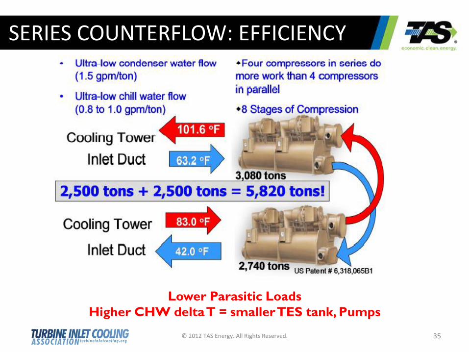
SERIES COUNTERFLOW: EFFICIENCY
© 2012 TAS Energy. All Rights Reserved. 35
Lower Parasitic Loads
Higher CHW delta T = smaller TES tank, Pumps

BEST PRACTICTES
SUPER PEAK – 12/10/2 (charge, partial discharge, SuperPeak)
• Max benefit, lowest parasitics
• Larger Secondary Pump Skid, TES Tank flow rate
DESIGN CONDITION
• Design condition (95°F drybulb, 75°F wetbulb)
• 24 hour design DAY
© 2012 TAS Energy. All Rights Reserved. 36
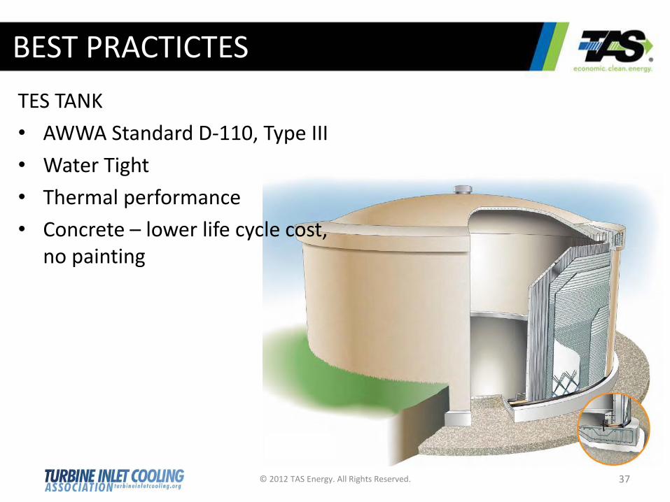
BEST PRACTICTES
TES TANK
• AWWA Standard D-110, Type III
• Water Tight
• Thermal performance
• Concrete – lower life cycle cost, no painting
© 2012 TAS Energy. All Rights Reserved. 37