TUBULAR RETRACTOR SYSTEM Surgical Technique
21
INSIGHT ™ TUBULAR RETRACTOR SYSTEM Surgical Technique Tubular access system for the posterior thoracolumbar spine
Transcript of TUBULAR RETRACTOR SYSTEM Surgical Technique

INSIGHT™
TUBULAR RETRACTOR SYSTEM
Surgical TechniqueTubular access system for the posterior thoracolumbar spine

Image Intensifier Control
▲ Warnings
This description alone does not provide sufficient background for direct use of DePuy Synthes products. Instruction by a surgeon experienced in handling these products is highly recommended.
Processing, Reprocessing, Care and Maintenance
For general guidelines, function control and dismantling of multi-part instruments, as well as processing guidelines for implants, please contact your local sales representative or refer to:
http://emea.depuysynthes.com/hcp/reprocessing-care-maintenance
For general information about reprocessing, care and maintenance of Synthes reusable devices, instrument trays and cases, as well as processing of Synthes non-sterile implants, please consult the Important Information leaflet (SE_023827) or refer to:
http://emea.depuysynthes.com/hcp/reprocessing-care-maintenance

Table of Contents
3INSIGHT™ Tubular Retractor System • Surgical Technique
Introduction INSIGHT™ Tubular Retractor System 4
AO Spine Principles 6
Surgical Technique Preparation 7
Surgical Technique 12
Indications and Contraindications 19
Bibliography 20
For product catalog contact your local DePuy Synthes representative
4 Surgical Technique • INSIGHT™ Tubular Retractor System
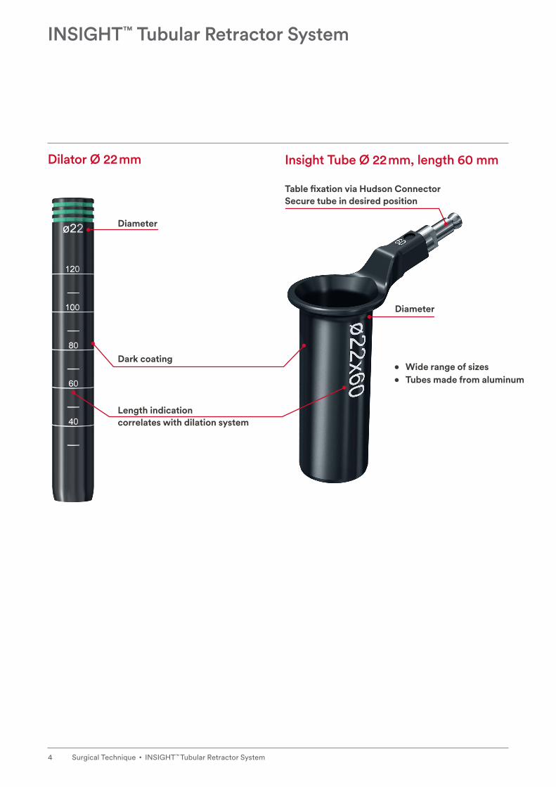
INSIGHT™ Tubular Retractor System
Introduction
Dilator Ø 22 mm Insight Tube Ø 22 mm, length 60 mm
Table fixation via Hudson Connector Secure tube in desired position
Diameter
Diameter
• Wide range of sizes
Length indication correlates with dilation system
Dark coating
• Tubes made from aluminum

5INSIGHT™ Tubular Retractor System • Surgical Technique
Product Overview
• Tubes made from aluminum
Insert dilators Insert Insight Tube Use instruments through tube
1. 2. 3. 4.
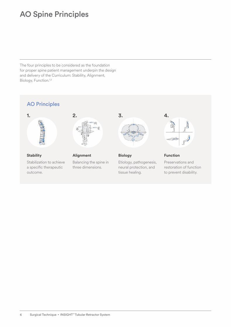
Stability
Stabilization to achieve a specific therapeutic outcome.
Alignment
Balancing the spine in three dimensions.
Biology
Etiology, pathogenesis, neural protection, and tissue healing.
Function
Preservations and restoration of function to prevent disability.
6 Surgical Technique • INSIGHT™ Tubular Retractor System
AO Spine Principles
AO Principles
The four principles to be considered as the foundation for proper spine patient management underpin the design and delivery of the Curriculum: Stability, Alignment, Biology, Function.1,2

7INSIGHT™ Tubular Retractor System • Surgical Technique
1. Patient positioningThe patient is placed in a prone position. To facilitate intra-operative exposure of the posterior disc space, the spine can be flexed.
• If a fusion procedure is being performed ensure the spine is returned to the physiological position before inserting trials and implants.
Preparation
Surgical Technique

8 Surgical Technique • INSIGHT™ Tubular Retractor System
2. Set up MIS Support System
MIS Support System
387.346 SynFrame Holding Base, insulated, for OR Table, dark blue
387.343 SynFrame Guiding Tube, for Angled Rod No. 387.344, for Basic System
03.612.012 Flex Arm – SynFrame Connection
03.612.010 Flex Arm
When working through a tubular access system, table mounting is very important. Therefore always use the INSIGHT Tubes in combination with the Synthes MIS support system which securely fixes the INSIGHT Tubes to the OR table.
• Two flex arms may be used simultaneously on the Flex Arm – SynFrame Connection for bilateral approaches.
Preparation

9INSIGHT™ Tubular Retractor System • Surgical Technique
2a. Secure holding baseInstall the holding base on the operative table by sliding in along a guide rail from the rail end. “TOP” must be visible on the clamp surface. Tighten the knob to secure it to the rail at the desired location.
Preparation

10 Surgical Technique • INSIGHT™ Tubular Retractor System
2b. Insert guiding tube into holding base
Insert a guiding tube into the holding base and lock it in place with the tightening knob.
2c. Insert flex arm bridge into guiding tube
Insert the tapered end of the flex arm bridge into the holding sleeve of the guiding tube until the desired shaft length is exposed.
Once the desired height is achieved, lock in place by using the clamp handle.
Preparation

11INSIGHT™ Tubular Retractor System • Surgical Technique
2d. Attach flex arm to flex arm bridgeSlide the flex arm clamp into the flex arm bridge. Turn the clamp knob clockwise to tighten the flex arm clamp. • Two flex arms may be used simultaneously on one
Flex Arm – SynFrame Connection.
▲▲ Precaution:
Flex arm tension should be fully released after each use to prevent instrument damage and allow proper instrument sterilization.
Preparation

12 Surgical Technique • INSIGHT™ Tubular Retractor System
1. Approach the spine
Instruments
02.606.001 Kirschner Wire Ø 1.6 mm with trocar tip, length 480 mm, Stainless Steel
02.606.003 Kirschner Wire Ø 1.6 mm without trocar tip, length 480 mm, Stainless Steel
The mini-open approach uses paramedian incision made through the skin and fascia approximately 2–3 cm (for PLIF) or 3–4 cm (for TLIF) from the midline. This allows muscle splitting within the multifidus and longissimus cleavage plane.
Determine the location of the skin incision using anatomic landmarks or radiographic imaging. Create an incision. The incision length should match the respective tube diameter (Ø 16–28 mm), then cut through the subcutaneous tissue and make a fascial incision to the same length.
Position the Kirschner Wire in the incision and advance it carefully while controlling the position under fluoroscopy. Fix the Kirschner Wire in the bony structure where you plan to do the minimally invasive procedure.
▲▲ Warning:
Ensure the Kirschner Wires remain securely in position throughout the entire duration of the procedure. The tip of the Kirschner Wire should be monitored by fluoroscopy to ensure it does not slip off the bony structures (e.g. facet joint) and penetrate dura or the nerve root.
Surgical Technique

13INSIGHT™ Tubular Retractor System • Surgical Technique
2. Dilate incision
Instruments
03.610.001 Dilator Ø 1.8/10.0 mm, cannulated, for Guide Wire Ø 1.6 mm
03.610.002 Dilator Ø 10.0/13.0 mm, for No. 03.610.001
03.610.003 Dilator Ø 13.0/16.0 mm, for No. 03.610.002
03.610.004 Dilator Ø 16.0/19.0 mm for No. 03.610.003
03.610.005 Dilator Ø 19.0/22.0 mm for No. 03.610.004
03.610.006 Dilator Ø 22.0/25.0 mm for No. 03.610.005
03.610.007 Dilator Ø 25.0/28.0 mm for No. 03.610.006
Insert the 1.8/10.0 mm dilator over the Kirschner Wire.Continue dilation placing the 10.0/13.0 mm dilator over the 1.8/10 mm dilator. Then place the 13.0/16.0 mm dilator over the 10.0/13.0 mm dilator.
If a larger diameter is required continue to dilate the incision by inserting dilator after dilator following the diameter sizes of the dilators.
▲▲ Warning:
Ensure the Kirschner Wire does not slip out before the tube is in place. The Kirschner Wires are long enough to be held in place by hand during soft tissue dilation.
Surgical Technique

14 Surgical Technique • INSIGHT™ Tubular Retractor System
3. Choose Insight Tube
Instruments
03.615.163–169 MIS Access Tube, size 16 × 30 mm–16 × 90 mm
03.615.193–199 MIS Access Tube, size 19 × 30 mm–19 × 90 mm
03.615.223–229 MIS Access Tube, size 22 × 30 mm–22 × 90 mm
03.615.253–259 MIS Access Tube, size 25 × 30 mm–25 × 90 mm
03.615.283–289 MIS Access Tube, size 28 × 30 mm–28 × 90 mm
Etched markings on the dilators indicate the length of the appropriate tube. The soft tissue coverage can vary between 30 and 90 mm.
Surgical Technique

15INSIGHT™ Tubular Retractor System • Surgical Technique
Surgical Technique
Choose the correct tube according to the last dilator. The etching of the dilator indicates the diameter of the tube and the etched ring marks indicate the length of the tube. Use the shortest allowable tube to access the posterior bony structures of the spine for less impact on instrument mobility.

16 Surgical Technique • INSIGHT™ Tubular Retractor System
Surgical Technique
4. Insert Insight TubeThe selected Insight Tube is inserted over the last dilator and pushed down.
Place the tube so that the Hudson connector is pointed away from the surgeon. This allows for a wide working area and better visibility.

17INSIGHT™ Tubular Retractor System • Surgical Technique
Surgical Technique
5. Connect Insight Tube to the flex arm
Connect the tube with the flex arm by pulling back the coupling on the flex arm and plug in the Hudson connector of the tube.
Position the tube in the desired working position and hold it in place.
Turn the tension knob on the flex arm until it is secured.
To reposition the tube, release the flex arm tension by turning the tension knob back. Place the tube in the desired position, then retighten the tension knob.

18 Surgical Technique • INSIGHT™ Tubular Retractor System
Surgical Technique
6. Remove Kirschner Wire and dilatorsAfter securing the Insight Tube with the flex arm, the Kirschner Wire and dilators can be removed one after another.
Perform the procedure (laminectomy, discectomy, etc.) using instruments through the tube.
The rest of the surgical steps are described in the corresponding surgical techniques of the chosen system.

19INSIGHT™ Tubular Retractor System • Surgical Technique
Please refer to the corresponding Instructions for Use for specific information on Intended use, Indications, Contraindications, Warnings and Precautions, Potential Adverse Events, Undesirable Side Effects and Residual Risks. Instructions for Use are available at www.e-ifu.com and/or www.depuysynthes.com/ifu.
Indications and Contraindications
Indications and Contraindications

20 Surgical Technique • INSIGHT™ Tubular Retractor System
1. Aebi M, Arlet V, Webb JK (2007): AOSPINE Manual (2 vols), Stuttgart, New York: Thieme.
2. Aebi M, Thalgott JS, Webb JK (1998): AO ASIF Principles in Spine Surgery. Berlin Heidelberg New York: Springer.
Bibliography
Bibliography

Manufactured or distributed by:Synthes GmbHEimattstrasse 34436 OberdorfSwitzerland
Tel: +41 61 965 61 11
www.jnjmedicaldevices.com
Note: For recognized manufacturer, refer to the product label.
Not all products may currently be available in all markets.
This publication is not intended for distribution in the USA.
Surgical techniques are available as PDF files at www.depuysynthes.com/ifu
© DePuy Synthes Spine, a division of Synthes GmbH 2021. All rights reserved.SE_842641_AA (036.001.035; DSEM/SPN/0215/0273) EOS: 175266-210428 EMEA.