TToottaall FFllooooddiinngg SSyysstteemmss
14
Jan-11 Rev. 9 bk Guideline for FM200 Systems Rev9 T T o o t t a a l l F F l l o o o o d d i i n n g g S S y y s s t t e e m m s s - - G G u u i i d d e e l l i i n n e e - - HFC-227 ea CF 3 -CHF-CF 3 Heptafluoropropane Note : This guideline has been prepared with the best information available at the time of publication. Changes in standards mentioned or technical changes may apply without further notice.
Transcript of TToottaall FFllooooddiinngg SSyysstteemmss
Jan-11 Rev. 9
bk Guideline for FM200 Systems Rev9
TT oo tt aa ll FF ll oo oo dd ii nn gg SS yy ss tt ee mm ss
-- GGuuiiddeelliinnee --
HHFFCC--222277 eeaa
CCFF33--CCHHFF--CCFF33
Heptafluoropropane
Note: This guideline has been prepared with the best information available at the time of publication. Changes in standards mentioned or technical changes may apply without further notice.

Jan-11 Rev. 9
Guideline For FM-200 Extinguishing Systems
bk Page 2 of 14
1) General Information
FM-200 has been developed as an alternative to Halon 1301, production of which ceased at the end of 1993,
under the agreed adjustments made to the Montreal Protocol in November 1992.
FM-200 contains no Bromine or Chlorine and has therefore an Ozone depleting potential of zero.
FM-200 systems utilize one or more storage containers arranged to provide the protected area with a pre-
determined quantity of gas.
FM-200 storage containers are designed to hold FM-200
in liquid form and Nitrogen, which is used to super-
pressurize the container to 24.8 bar (360 psi) at 20°C.
Handling and Installation of FM-200 equipment should only be carried out by persons experienced in dealing
with this type of equipment.
2) Properties of FM-200
FM-200 is stored as a liquefied compressed gas and is discharged into the protected area as a vapour.
FM-200 (HFC-227ea) is a clean, gaseous agent containing no particles or oily residues. It is produced under
ISO 9002 guidelines to strict manufacturing specifications ensuring product purity. FM-200® leaves no residue
or oily deposits on delicate electronic equipment, and can be removed from the protected space by ventilation.
The present understanding of the functioning of FM-200 is that 80% of its fire fighting effectiveness is
achieved through heat absorption and 20% through direct chemical means (action of the fluorine radical on the chain reaction of a flame).
FM-200 decomposes at temperatures in excess of 500°C and it is therefore important to avoid applications
involving hazards where continuously hot surfaces are involved. Upon exposure to the flame FM-200 will
decompose to form halogen acids. Their presence will be readily detected by a sharp, pungent odour before maximum hazardous exposure levels are reached. It has been concluded from fire toxicity studies that decomposition products from the fire itself specially carbon monoxide, smoke, oxygen depletion and heat may create a greater hazard.
Chemical Formula: CF3CHFCF3
Boiling Point @ 1 atm: -16.4 °C
Vapour Pressure @ 20°C: 3.91 bar (56.7 psi)
Vapour Density @ 20°C: 31.18 kg/m³ (1.95 lb/ft³)
Liquid Density @ 20°C: 1407 kg/m³
3) Approvals
The FM-200 system and components used in the TSP extinguishing system have been tested and approved by LPCB (European System) and UL/FM (non-European System).
Only approved components may be used in the FM-200 system.

Jan-11 Rev. 9
Guideline For FM-200 Extinguishing Systems
bk Page 3 of 14
4) Safety Margins
Use Conc. NOAEL* Safety Margin
Novec 1230™ 4% - 6% 10% 67% - 150%
Halon 1301 5% 5% Nil
FM-200® 6,4% - 8,7% 9% 3% - 29%
* No Observable Adverse Effect Level Low Observable Adverse Effect Level (LOAEL) for FM-200
® is >10.5% !
5) Environmental Comparison
Ozone Depletion Potential
(ODP)
Global Warming Potential
(GWP)
Atmospheric Lifetime
(years)
Novec 1230™ 0 1 0,014
Halon 1301 12 6900 65
HFC-227ea 0 3500 33
* IPCC 2001
6) General System Design
Total Flooding is the only approved application method for FM-200 systems! Manifolded System Modularized System
All cylinders the same size
and the same filling!

Jan-11 Rev. 9
Guideline For FM-200 Extinguishing Systems
bk Page 4 of 14
7) Hazard Analysis
Note: A thorough hazard analysis is important for a qualified quotation. The following questions should be answered:
PROJECT: (enter name if applicable; country must be indicated)
Name Country
SUPPRESSION SYSTEM:
CO2 HP FM-200 Novec™ i2/i3 Inergen Other (specify) __________________________ Type
NFPA/FM NFPA/UL ISO VdS Other (specify) __________________________ Design Standard / Approval
DOT TPED None Other (specify) __________________________ Agent Container Approval
Electric Manual Pneumatic System Release
Inside Hazard Outside Hazard: ________ [m] horizontal distance ________ [m] vertical distance Agent Container Location
HAZARD:
No. Name Hazardous Material
[°C] [°C] [m] Minimum Temperature Maximum Temperature Altitude above/below sea level
Hazard Dimensions:
[m] [m] [m²] Length Width Floor Area (alternative)
[m] [m] [m] Height of Ceiling Void (if applicable) Height of Room (excl. ceiling/floor void) Height of Floor Void (if applicable)
Impermeable Building Structures: [m³] Only permanent impermeable building structures within the area may be deducted from the gross volume Note In the following cases please supply additional sketches/drawings with dimensions and any relevant details:
irregular room shapes ceiling obstructions such as beams greater than 300 mm (12 in.) height other unusual conditions.
Further Information / Comments:

Jan-11 Rev. 9
Guideline For FM-200 Extinguishing Systems
bk Page 5 of 14
8) System Design
The system design requires the following steps:
1. Check on design standard / hazardous material involved to get the design concentration 2. Determination of net* hazard volume.
*Only permanent impermeable building structures within the hazard may be deducted from the overall hazard volume. 3. Determination of the extinguishing agent quantity 4. Check the max. reached concentration 5. Determination of number and size of agent containers. 6. Determination of nozzle size and quantity. 7. Determination of pipe sizes and pipe run.
Note: Pipes and fittings are generally not supplied by TSP.
8.1) FM-200® Design Concentrations
ISO 14520 CEA 4045 NFPA 2001 EN 15004
Surface Class A 7,9 % 8,4 % 6,25-7 % 3)
7,9 %
Higher Hazard Class A 1)
8,5 % --- --- 8,5 %
Class B (Heptane) 2)
9,0 % 8,8 % 8,7 % 3)
9,0 %
1)
ISO 14520-1 § 7.5.1.3 І EN 15004-1 § 7.5.1.3
It is recognized that the wood crib and polymeric sheet class A fire tests may not adequately indicate extinguishing concentrations suitable for the protection of certain plastic fuel hazards (e.g. electrical and electronic type hazards involving grouped power or data cables such as computer and control room under-floor voids, telecommunication facilities, etc.). An extinguishing concentration not less than that determined according to clause 7.5.1.3, or not less than 95% of that determined from the heptane fire test in Annex C, Clause C.6.2, whichever is the greater, should be used under certain conditions. These conditions may include:
(1) Cable bundles greater than 100 mm in diameter (2) Cable trays with a fill density greater than 20 percent of the tray cross-section (3) Horizontal or vertical stacks of cable trays (closer than 250 mm) (4) Equipment energized during the extinguishment period where the collective power consumption
exceeds 5 kW NFPA 2001 - 2008 Edition A.5.4.2.2 (7)(g)
Where any of the following conditions exist, higher extinguishing concentrations might be required:
(1) Cable bundles greater than 100 mm in diameter (2) Cable trays with a fill density greater than 20 percent of the tray cross-section (3) Horizontal or vertical stacks of cable trays (closer than 250 mm) (4) Equipment energized during the extinguishment period where the collective power consumption
exceeds 5 kW
2) For design concentrations for any other class B fuel see design standards or contact Tyco Technical Service.
3) Values are from NFPA 2001 - 2008 Edition Table A.5.4.2.2(b)
The Pyrochem FM-200® design manual lists 7,17% for class A and 90,% for class B (Heptane).
Acc. to Pyrochem Bulletin 2168, UL accepts 6,4% minimum design concentration for class A and C.
Important!
These design concentrations are not applicable (and are not to be used) for Marine applications.

Jan-11 Rev. 9
Guideline For FM-200 Extinguishing Systems
bk Page 6 of 14
AltF CCVQ
8.2) FM-200® Flooding Factor Table
Table 1: FM-200 weight requirements per volume of protected space:
8.3) Altitude Correction Factors
At elevations above sea-level, FM-200 has a greater specific volume because of the reduced atmospheric
pressure. A system designed for sea-level conditions will therefore develop an actual higher concentration at levels above sea-level and an actual lower concentration at levels below sea-level. Table 2:
8.4) Determination of FM-200 Quantity
Where Q = Agent quantity required [kg] V = Hazard volume [m³]
CF = Flooding factor [kg/m³] (see Table 1) CAlt = Altitude correction factor (see Table 2)

Jan-11 Rev. 9
Guideline For FM-200 Extinguishing Systems
bk Page 7 of 14
Example: Type of hazard: Computer room (surface class A)
Design Standard: ISO 14520 Volume: 8,0 m x 4,25 m x 2,5 m = 85 m³ Minimum hazard temperature: 20°C Maximum hazard temperature 30°C Altitude: 1500 m
Round up to the next full kg Required agent quantity = 45 kg FM-200 .
8.5) Check the max. reached concentration
To check the concentration C reached in a hazard the following formula can be used:
Where Q = agent quantity supplied from the system [kg] V = hazard volume [m³] s = specific vapor volume [m³/kg] = 0.1269+0.0005131*T at sea level ! T = max. hazard temperature [°C] Example: Type of hazard: Computer room (surface class A)
Design Standard: ISO 14520 Gros volume: 8,0 m x 4,25 m x 2,5 m = 85 m³ Minimum hazard temperature: 20°C Maximum hazard temperature 30°C Altitude: 1500 m
A quantity of 45 kg FM-200 has been calculated at an altitude of 1500 m.
At sea level this would result in 45 kg / 0,83 = 54.22 kg FM-200
What concentration is reached at the max. hazard temperature of 30°C ? S = 0.1269 + 0.0005131 * 30 = 0.1423
Concentration @ 30°C is less than NOAEL (9%) – okay for occupied space !
]44.13[kg0.830.625485Q
s)(QV
100sQC
%32,872,92
55.771
)1423.022.54(85
1001423.022.54C

Jan-11 Rev. 9
Guideline For FM-200 Extinguishing Systems
bk Page 8 of 14
8.6) Determination of number and size of containers
Each container assembly consists of
FM-200 container
FM-200 valve with pressure gauge
Siphon tube Containers are painted red as standard. Containers are fitted with a label which provides handling, maintenance and recharge instructions. All containers are designed for vertical mounting only.
Each assembly may be provided with a range of FM-200 fills to suit the design requirements.
After filling, the containers are super-pressurised with dry nitrogen to 24.8 bar +5% (at a temperature of 20°C).
Table 3a: Table 3b:
FM-200 Container FM-200 Container
Container manufactured to meet 84/527/EEC (TPED) Container manufactured to DOT
Container Size
Container Diameter
Ht. to Valve Outlet
Tare Weight*
Min. FM 200
Filling
Max. FM 200
Filling
Max. Gross Weight
Container Size
Container Diameter
Ht. to Valve Outlet
Tare Weight*
Min. FM 200
Filling
Max. FM 200
Filling
Max. Gross Weight
(litre) (mm) (mm) (kg) (kg) (kg) (kg) (litre) (mm) (mm) (kg) (kg) (kg) (kg)
--- --- --- --- --- --- --- 4.5 178 280 7.7 2.3 4.5 12.2
8 254 300 14.8 4.0 8.0 22.8 8 254 300 14.8 4.0 8.0 22.8
16 254 499 18.4 8.0 16.0 34.4 16 254 499 18.4 8.0 16.0 34.4
32 254 831 26.1 16.0 32.0 58.1 32 254 831 26.1 16.0 32.0 58.1
52 406 593 49.1 26.0 52.0 101.1 52 406 593 49.1 26.0 52.0 101.1
106 406 1018 71.8 53.0 106.0 177.8 106 406 1018 71.8 53.0 106.0 177.8
147 406 1352 89.9 73.5 147.0 236.9 147 406 1352 89.9 73.5 147.0 236.9
180 406 1631 105.8 90.0 180.0 285.8 180 406 1631 105.8 90.0 180.0 285.8
--- --- --- --- --- --- --- 343 610 1466 207.0 171.5 343.0 550.0
Note: 1) In EU countries only TPED compliant containers can be used. 2) Unless a hydraulic flow calculation is done, approximate 80% of the max. filling should be used to
determine a container size (this is a recommendation from experience, not a fixed technical value). Example: using TPED container
Required agent quantity = 41 kg FM-200
Container size Min. Filling Max. Filling 80% Max. Filling* Actuall Fill%
32 l 16,0 kg 32,0 kg 25,6 kg 128% > 100% 52 l 26,0 kg 52,0 kg 41,6 kg 79% o.k 106 l 53,0 kg 106,0 kg 84,8 kg 39% min. filling not reached
* experience value
1 x 52 liter container required – filled with 41 kg FM-200 .

Jan-11 Rev. 9
Guideline For FM-200 Extinguishing Systems
bk Page 9 of 14
8.7) Determination of number and size of nozzles
FM-200 Discharge Nozzles: Nozzle Coverage:
180° Pattern 360° Pattern
Number of ports 7 8
Available size 15/20/25/32/40/50 mm
Max. area of coverage see figure
Max. coverage height 4.87 m
Example: Hazard = 8,0 m x 4,25 m x 2,5 m
45 kg FM-200
Note:
Discharge time for a FM-200 system is max. 10 seconds.
A) Number of nozzles: Check of nozzle coverage check nozzle coverage vs. hazard area check max. coverage height (4.87 m) vs.
height of hazard 1 nozzle 180° or 1 nozzle 360° possible. B) Nozzle size: check agent flow [kg/s] per nozzle and
determine nozzle size from table 4 (see § 8.8) Agent flow = 4.5 kg/s Nozzle size = 32 mm (1 1/4")
0.5 L = 4.0 m
8.0 m
4.25 m
180° Nozzle: S180 = 5.9 m
360° Nozzle: S360 = 4.53 m
0.5 W = 2.125 m

Jan-11 Rev. 9
Guideline For FM-200 Extinguishing Systems
bk Page 10 of 14
8.8) Determination of pipe sizes and pipe run
System Limitations
Flow limitations at T-splits
Bull Tee Side Tee
Pipe arrangments at T-splits
Correct Incorrect
10-30%
90-70%
70-30%
30-70%
minimum length of 10 x nominal pipe diameter
Jan-11 Rev. 9
Guideline For FM-200 Extinguishing Systems
bk Page 11 of 14
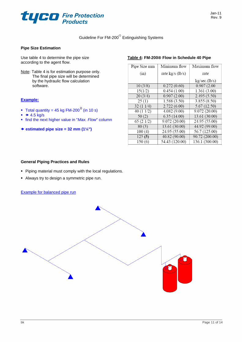
Pipe Size Estimation
Use table 4 to determine the pipe size Table 4: FM-200 Flow in Schedule 40 Pipe according to the agent flow. Note: Table 4 is for estimation purpose only.
The final pipe size will be determined by the hydraulic flow calculation software.
Example:
Total quantity = 45 kg FM-200 (in 10 s)
4.5 kg/s find the next higher value in "Max. Flow" column estimated pipe size = 32 mm (1¼") General Piping Practices and Rules Piping material must comply with the local regulations.
Always try to design a symmetric pipe run.
Example for balanced pipe run

Jan-11 Rev. 9
Guideline For FM-200 Extinguishing Systems
bk Page 12 of 14
9) Pressure Venting
The designer of a fire suppression system should be aware, that the discharge of any gaseous extinguishing agent into an enclosure will change the pressure within that enclosure, which could affect the structural integrity of the enclosure.
NFPA 2001 § 5.3.6 The protected enclosure shall have the structural strength and integrity necessary to contain the agent discharge. If the developed pressures present a threat to the structural strength of the enclosure, venting shall be provided to prevent excessive pressures. For pressure relief vent area or equivalent leakage area, see 5.1.2.2(28) Fire Industry Association (FIA) UK: Guidance on Venting of Gas Systems_Issue 1 publication_9th Nov 2010.
"The US based Fire Suppression Systems Association (FSSA) have issued a “Guide to Estimating Enclosure Pressure and Pressure Relief Vent Area for Applications Using Clean Agent Fire Extinguishing Systems”. This guidance has been based upon experimental data attained via collaboration with various industry participants, including a number of multinational organisations. The FSSA work is by far the most in-depth investigation to-date, on the estimation of enclosure pressure and total vent area requirements." The following input parameters are required to use the calculation methodology:
• Extinguishing agent • Protected enclosure volume • Extinguishing system discharge time • Extinguishing concentration • Relative humidity of enclosure.
1. If the enclosure strength is known it is possible to calculate the required total vent area.
2. If the total vent area is known then it is possible to calculate the expected pressure excursion following an extinguishing system discharge.
Parameter Unit Definition
+vePE Pa Positive Pressure Excursion
-vePE Pa Negative Pressure Excursion
TotalVentArea m² the sum of the free vent area and the natural leakage area
Volume m³ Protected enclosure volume
Conc % Suppressant concentration used in the protected enclosure
td s Gaseous fire fighting system discharge time
%RH % Relative humidity within the enclosure
+veEPL Pa Enclosure positive pressure limit
-veEPL Pa Enclosure negative pressure limit
+veFVA m² Positive free vent area required to ensure that the positive pressure excursion is below the enclosure positive pressure limit (+veEPL)
-veFVA m² Negative free vent area required to ensure that the negative pressure excursion is below the enclosure negative pressure limit (-veEPL)
CAUTION: The magnitude of both +veEPL and –veEPL for each extinguishant have limits of applicability. The calculation methodology is based on experimental data and therefore the prediction of the
calculation tool must remain within the data envelope investigated. Calculations based on parameters outside the limits of applicability will not be accurate and it is strongly advised that such calculations are treated accordingly.
If the relative humidity level is not known, 50% is the recommended value to use.

Jan-11 Rev. 9
Guideline For FM-200 Extinguishing Systems
bk Page 13 of 14
HFC-227-ea (FM-200®): Limits of applicability:
6s ≤ td ≤ 10s 6.25% ≤ Conc ≤ 10.5% 20% ≤ RH% ≤ 80% +veEPL ≤ 380 Pa -veEPL ≤ -1000 Pa
1. Required Total Vent Area for HFC-227-ea (FM-200
®):
Enclosure strength must be known
Positive Total Vent Area Negative Total Vent Area
Example: Hazard volume = 120 m³ Design concentration = 7.9% Hazard pressure limit = 200 Pa Discharge time = 9.6 seconds
(Calculation done with "Pressure Vent Area Calculation BKR Rev.110128.xlsm")
Required Total Vent Area

Jan-11 Rev. 9
Guideline For FM-200 Extinguishing Systems
bk Page 14 of 14
2. Pressure Excursion for HFC-227-ea (FM-200®):
Total vent area must be known (total vent area is defined as the sum of the free vent area and the natural leakage area.)
+vePE
-vePE
Example: Hazard volume = 120 m³ Design concentration = 7.9% Total vent area = 0.02 m² Discharge time = 9.6 seconds
(Calculation done with "Pressure Vent Area Calculation BKR Rev.110128.xlsm")
Pressure Excursion