PPVV SSyysstteemmss MMaannuuaall - JICA
45
Master Plan Study for Utilization of Solar Energy in the Federal Republic of Nigeria P P P V V V S S S y y y s s s t t t e e e m m m s s s M M M a a a n n n u u u a a a l l l October 2006 Japan International Cooperation Agency (JICA)
Transcript of PPVV SSyysstteemmss MMaannuuaall - JICA

Master Plan Study for Utilization of Solar Energy
in the Federal Republic of Nigeria
PPPVVV SSSyyysssttteeemmmsss MMMaaannnuuuaaalll
October 2006
Japan International Cooperation Agency (JICA)

Preamble
In response to the request of the Government of the Federal Republic of Nigeria (hereinafter referred to as “Nigeria”), the Government of Japan decided to conduct Master Plan Study for Utilization of Solar Energy in the Federal Republic of Nigeria (Hereinafter referred to as “Study”) in accordance with the relevant laws and regulations in force in Japan and entrusted the Study to the Japan International Cooperation Agency (hereinafter referred to as “JICA”), the official agency responsible for the implementation of the technical cooperation programs in the Government of Japan.
JICA sent the Master Plan Study Team (hereinafter referred to as “Team”) to Nigeria and conduct the Study in close cooperation with the authorities concerned in Nigeria. The Study includes a Pilot Project (hereinafter referred to as “Project”) using Photovoltaic (PV) systems, which is implemented in one (1) village each in Jigawa State, Ondo State, and Imo State.
The scope of the Project in Jigawa state includes the procurement, installation, and maintenance of the PV systems consisting of one (1) Battery Charging Station (BCS) including twenty (20) electrified households, one (1) Public Facility, forty (40) Solar Home Systems (SHSs), and ten (10) Street Lightings.
Meanwhile, the PV systems consist of one (1) Public Facility including one (1) PV vaccine refrigerator, sixty (60) SHSs, and ten (10) Street Lightings in Ondo state; the PV systems consist of one (1) Public Facility, eighty (80) SHSs, and ten Street Lightings (10) in Imo State,
The installation of the PV systems is completed late in June 2006, and the Project will be monitored up to February 2007 to evaluate the sustainability of PV systems in Nigeria.
The manual is specially prepared to instruct the concept and maintenance of PV systems of the Project and consists of three chapters: for users, for maintenance staff, and for engineers. The contents are as follows:
For Users
The chapter starts with the components of PV systems and illustrates what the users should do and should not do to keep the PV systems in good condition.
For Maintenance Staff
The chapter describes what the maintenance staff should do as a routine work. It also contains how to deal with the troubles of the PV systems.
For Engineers
The chapter starts with the general description of PV generation. For future reference, it also describes PV systems design.

PPPVVV SSSyyysssttteeemmmsss MMMaaannnuuuaaalll
FFFooorrr UUUssseeerrrsss

Maser Plan Study for Utilization of Solar Energy in the Federal Republic of Nigeria PV Systems Manual for Users
1.1 Components of PV Systems
JICA provides two kinds of PV systems for independent house use―Solar Home System (SHS) and Battery Charging Station (BCS). The SHS consists of the following components:
• PV Module: Getting the sunlight, the PV module generates electricity,
• Storage Battery: The electricity generated by the PV module during the daytime charges the storage battery. At night, the battery discharges and supplies electricity. JICA provides a sealed type battery which is maintenance-free,
• Charge Controller: The charge controller controls the charge/discharge of the battery and has a function to prevent the battery from over-discharge,
• Circuit Breaker: In case of short circuit, the circuit breaker automatically cuts off the circuit,
• Switch: The switch is used to turn on and off the lightings,
• Outlet: The outlet is used for DC appliances such as a radio, black and white television set, etc, and
• Lighting: The lighting, Compact Fluorescent Lump (CFL), is specially designed for DC use and is more efficient than an ordinary AC bulb.
Meanwhile, the BCS consists of the same components as the SHS except that the PV modules are not installed independently but aggregated at the station as a PV array. The Users of the BCS are required to take their batteries to the station every 4 or 5 days and charge them. Additionally, the battery is flooded type which is required to fill distilled water regularly.
Fig. 1-1 shows the configuration of PV systems.
(a) SHS (b) BCS
Lighting
Charge Controller
Storage Battery
PV module
Circuit Breaker
Switch
Outlet
User A
User B
User A User B
PV array
Battery Charger
Station
Fig. 1-1 Configuration of PV Systems
1 - 1

Maser Plan Study for Utilization of Solar Energy in the Federal Republic of Nigeria PV Systems Manual for Users
1.2 Feature of PV Systems
Table 1-1 illustrates the feature of PV systems.
Table 1-1 Feature of PV Systems
Reliable You can use electricity whenever you need power.
Simple When you need electricity, you just turn on the switch or plug in an appliance.
Ecologically Friendly During the generation, the PV systems do not produce any harmful substance.
Having Limitations You can not use the PV systems all day long. In addition, AC appliances are not applicable.
12
6
39
Not all day long
No AC Appliance
1.3 Concept of PV Systems
The output of the PV module totally depends on the weather. The more sunshine the PV module receives, the more electricity you can use. Meanwhile, the storage battery provides electricity at night. Even though you can not get any sunshine for a few days during the rainy season, the battery sustains the system and supplies you with electricity. However, the charge controller automatically disconnects the load when the battery voltage becomes too low to sustain the system.
Fig. 1-2 illustrates the concept of PV systems.
1 - 2

Maser Plan Study for Utilization of Solar Energy in the Federal Republic of Nigeria PV Systems Manual for Users
Energy Generated
Energy Stored
Energy Generated
Energy Stored
1st Day
Energy Generated
Energy Stored
PV Battery Load
ConsumedEnergy
2nd Day
PV Battery Load
Loss
Surplus Stored Energy
Loss
Stored Energy
Surplus
ConsumedEnergy
3rd Day
PV Battery Load
Loss
Stored Energy
ConsumedEnergy
• Stop using electricity for a day, and• Wait till the battery voltage
recovers and the charge controller automatically reconnect the load.
The PV module generates electricity, and surplus energy is stored in the battery.
In case of rain, the PV module does not generate electricity at all, however, the battery supplies electricity.
When the battery runs out of the energy stored, the charge controller automatically disconnects the load.
Fig. 1-2 Concept of PV Systems
1.4 Plan of Energy Consumption
Generally, the northern part of Nigeria shows the better solar irradiation conditions, in other words, you can use the PV systems longer in the north if the systems are identical. However, the hour of use depends on the load you use. So you need to make a plan of energy consumption considering the load you use.
1 - 3

Maser Plan Study for Utilization of Solar Energy in the Federal Republic of Nigeria PV Systems Manual for Users
Table 1-2 shows the daily limits of energy consumption which are calculated based on the solar irradiation conditions and specification of PV systems. As you see, high solar irradiation in Jigawa state allow you to consume energy most. For the purpose of using the PV system for as long a time as possible, you shall use energy within the limitation.
Table 1-2 Limit of Energy Consumption at SHS
Jigawa Ondo Imo
Minimum Average solar irradiation [kW/m2-day] 5.34 3.50 3.73 Capacity of PV module [W] 60 60 62 Lighting [W] 15 x 2 15 x 2 11 x 2 Limit of energy consumption [Wh/day] 120 85 90
Table 1-3 shows a quick reference matrix of energy consumption. First you select a nominal input of the load you use in the column of Watt, and then you find out energy consumption in Watt-hour in the same row depending on the time of use.
Table 1-3 Quick Reference Matrix of Energy Consumption in Watt-hour
Time Watt 10 min 20 min 30 min 1 hour 2 hour 3 hour 4 hour 5 hour
1 0.2 0.3 0.5 1.0 2.0 3.0 4.0 5.0 2 0.3 0.7 1.0 2.0 4.0 6.0 8.0 10.0 5 0.8 1.7 2.5 5.0 10.0 15.0 20.0 25.0 9 1.5 3.0 4.5 9.0 18.0 27.0 36.0 45.0
10 1.7 3.3 5.0 10.0 20.0 30.0 40.0 50.0 11 1.8 3.7 5.5 11.0 22.0 33.0 44.0 55.0 15 2.5 5.0 7.5 15.0 30.0 45.0 60.0 75.0 20 3.3 6.7 10.0 20.0 40.0 60.0 80.0 100.0
The following calculation shows an example of plan of energy consumption. In case of Jigawa, an nominal input of the two sets of lighting is 30 Watt. If you use them for 3.5 hours, the energy consumption yields 105 Watt-hour. Meanwhile, the energy consumption of radio for 3.0 hours is 15 Watt-hour, and we derive an accumulated energy consumption of 120 Watt-hour which meets the requirement of limit in Table 1-2.
Jigawa) Light 30 Watt x 3.5 hour = 105.0 Wh Radio 5 Watt x 3.0 hour = 15.0 Wh Total 120.0 Wh
1.5 Points of Remember
In order to keep the PV systems in good condition, you should do and should not to do as illustrated in Table 1-4.
1 - 4

Maser Plan Study for Utilization of Solar Energy in the Federal Republic of Nigeria PV Systems Manual for Users
Table 1-4 Points of Remember
Should remove obstacles from the PV module to get as much sunshine as possible.
Should keep the PV module surface clean.
SHS SHS
Should not hang the laundry on the cable to dry.
Should keep the battery in the battery box and lock it.
SHS SHS/BCS
Should not put the battery sideways and leave any object on the battery box.
Should not connect the load to the battery terminal directly and connect the batteries in parallel.
SHS/BCS SHS/BCS
Should take the battery to the station every 4 or 5 days and recharge it.
Should use a proper tool and be careful not to cause short circuit.
BCS BCS
Turn off the switch before connect/disconnect the cable
Take the batter to the station and recharge it
1 - 5

PPPVVV SSSyyysssttteeemmmsss MMMaaannnuuuaaalll
FFFooorrr MMMaaaiiinnnttteeennnaaannnccceee SSStttaaaffffff
Maser Plan Study for Utilization of Solar Energy in the Federal Republic of Nigeria PV Systems Manual for Maintenance Staff
2.1 Components of PV Systems
JICA provides four kinds of PV systems―Battery Charging Station (BCS), Public Facility, Solar Home System (SHS), and Street Lighting. The components of the above PV systems are similar and have the following functions:
• PV Module/Array: Getting the sunlight, the PV module generates electricity,
• Storage Battery: The electricity generated by the PV module during the daytime charges the storage battery. At night, the battery discharges and supplies electricity. JICA provides sealed type batteries for SHSs and flooded type batteries for BCS households,
• Battery Charger: The charger is used to charge the storage batteries at BCS,
• Charge Controller: The charge controller controls the charge/discharge of the battery and has a function to prevent the battery from over-discharge,
• Circuit Breaker: In case of short circuit, the circuit breaker automatically cuts off the circuit,
• Switch: The switch is used to turn on and off the lightings,
• Outlet: The outlet is used for DC appliances such as a radio, black and white television set, etc,
• Lighting: The lighting, Compact Fluorescent Lump (CFL), is specially designed for DC use and is more efficient than an ordinary AC bulb, and
• PV Vaccine Refrigerator: The refrigerator is certified by the World Health Organization (WHO) and is specially designed for the purpose of preserving vaccines.
All the PV systems of the Project are operated at DC 12 V. Therefore, the Users are required to be careful when they choose the components of the system.
Fig. 2-1 illustrates the configuration of PV systems.
(c) SHS (a) BCS
Lighting
Charge Controller
Storage Battery
PV module
CircuitBreaker
Switch
Outlet
User User
PV array
Battery Charger
Station
(b) Public Facility (d) Street Lighting
PV Vaccine Refrigerator (for Ondo state)
Lighting
Battery
Box
Fig. 2-1 Configuration of PV Systems
2 - 1

Maser Plan Study for Utilization of Solar Energy in the Federal Republic of Nigeria PV Systems Manual for Maintenance Staff
Table 2-1 to 3 illustrates the specification of the components in each state respectively.
Table 2-1 Specification of the Components in Jigawa State
Item Specification
a. BCS i) Station
PV Module Polycrystal 60 W x 18 units Charge Controller 12 V, 6 A x 1 unit Battery Charger 12 V, 20 A x 5 units Storage Battery Sealed type for cycle use, 200 Ah x 1 unit Lighting 12 V, 15 W Fluorescent Lamp x 2 units
ii) Household(per household) Charge Controller 12 V, 6 A x 1 unit Storage Battery Flooded type for trickle use, 88 Ah x 1 unit Lighting 12 V, 15 W Fluorescent Lamp x 2 units
b. Public Facility PV Module Polycrystal 60 W x 6 units Charge Controller 12 V, 20 A x 1 unit Storage Battery Sealed type for cycle use, 200 Ah x 2 units Lighting 12 V, 15 W Fluorescent Lamp x 12 units
c. SHS(per household) PV Module Polycrystal 60 W x 1 unit Charge Controller 12 V, 6 A x 1 unit Storage Battery Sealed type for cycle use, 65 Ah x 1 unit Lighting 12 V, 15 W Fluorescent Lamp x 2 units
d. Street Lighting(per light) PV Module Polycrystal 60 W x 1 unit Charge Controller 12 V, 10 A x 1 unit, timer function Storage Battery Sealed type for cycle use, 65 Ah x 1 unit Lighting 12 V, 18 W Sodium Lump x 1 unit
Table 2-2 Specification of the Components in Ondo State
Item Specification
a. Public Facility i) Lighting
PV Module Polycrystal 60 W x 6 units Charge Controller 12 V, 20 A x 1 unit Storage Battery Sealed type for cycle use, 200 Ah x 2 units Lighting 12 V, 15 W Fluorescent Lamp x 10 units
ii) PV Vaccine Refrigerator PV Vaccine Refrigerator 38.7 liter x 1 unit PV Module Polycrystal 60 W x 4 units Charge Controller 12 V, 15 A x 1 unit Storage Battery Sealed type for cycle use, 200 Ah x 1 unit, 100 Ah x 1 unit
b. SHS(per household) PV Module Polycrystal 60 W x 1 unit Charge Controller 12 V, 6 A x 1 unit Storage Battery Sealed type for cycle use, 65 Ah x 1 unit Lighting 12 V, 15 W Fluorescent Lamp x 2 units
c. Street Lighting(per light) PV Module Polycrystal 60 W x 1 unit Charge Controller 12 V, 10 A x 1 unit, timer function Storage Battery Sealed type for cycle use, 65 Ah x 1 unit Lighting 12 V, 18 W Sodium Lump x 1 unit
2 - 2

Maser Plan Study for Utilization of Solar Energy in the Federal Republic of Nigeria PV Systems Manual for Maintenance Staff
Table 2-3 Specification of the Components in Imo State
Item Specification
a. Public Facility PV Module Polycrystal 62 W x 8 units Charge Controller 12 V, 30 A x 1 unit Storage Battery Sealed type for cycle use, 105 Ah x 4 units Lighting 12 V, 11 W CFL x 12 units
b. SHS(per household) PV Module Polycrystal 62 W x 1 unit Charge Controller 12 V, 6 A x 1 unit Storage Battery Sealed type for cycle use, 60 Ah x 1 unit Lighting 12 V, 11 W CFL x 2 units
c. Street Lighting(per light) PV Module Polycrystal 62 W x 1 unit Charge Controller 12 V, 10 A x 1 unit, timer function Storage Battery Sealed type for cycle use, 60 Ah x 1 unit Lighting 12 V, 20 W CFL x 1 unit
2.2 Maintenance Works
Generally, the PV systems do not need complicated maintenance works except filling distilled water in the flooded type batteries. You are required to check out the systems regularly and keep them in good condition.
The Points of remember are illustrated in the Table 2-4.
Table 2-4 Points of Remember
Should use proper tools during the maintenance work.
Should turn off the breaker and switch and check the voltage before the work.
Turn off
Plug off
Check the voltage
V
Should use components which are designed for DC 12 V use.
Should fasten the screws if they are loose and clean the inside of the boxes.
6 V
12 V
24 V
Charge Controller
2 - 3
Maser Plan Study for Utilization of Solar Energy in the Federal Republic of Nigeria PV Systems Manual for Maintenance Staff
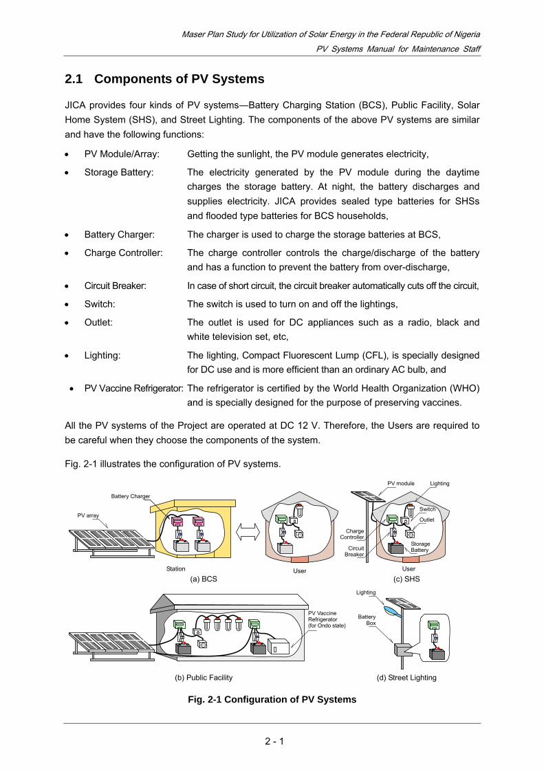
Should remove obstacles from the PV arrays.
Should keep the PV arrays surface clean (Clean them up twice a month)
Should connect the cable in the order of the terminal number when you replace the charge controller.
Should disconnect the cable in the opposite order of the terminal number when you replace the charge controller.
Should be careful not to cause short circuit. Should confirm that the green light is on when the sunshine is present.
Should connect the jumper when a sealed type battery is used.
Should remove the jumper when a flooded type battery is used.
4 +
3 -
2+
1 -
6 +
5 -
Turn off the switch/breaker and thenconnect the cables in the order of 1 2 3 4 5 6
4+
3-
2+
1-
6 +
5 -
Turn off the switch/breaker and thendisconnect the cables in the order of 6 5 4 3 2 1
Clean up the surface twice a month
Charging Charge Controller
4+
3-
2+
1-
6 +
5 -
4 +
3 -
2+
1 -
6 +
5 -
With the jumper, the charging voltage becomes 14.1 V for a sealed type battery.
4+
3-
2+
1-
6 +
5 -
Without the jumper, the charging voltage becomes 14.4 V for a flooded type battery.
2 - 4

Maser Plan Study for Utilization of Solar Energy in the Federal Republic of Nigeria PV Systems Manual for Maintenance Staff
Should confirm the level of electrolyte if a flooded type battery is used and fill distilled water up to the upper level.
Should replace the used batteries with the new ones at once.
New
Used
New
New
Upper Level
Do not use well water. Use only distilled water.
Lower Level
2.3 Trouble Shooting
Most troubles can be checked at the terminals of the charge controller. In case that the User experiences a blackout, you shall check the system as follows:
a. Load Disconnection
• Check the indicator on the charge controller. If the red light is on, the charge controller has disconnected the load automatically because the battery voltage is too low to sustain the system.
• Make the User stop using electricity for a day and wait till the battery voltage recovers.
• When the battery voltage exceeds 12.6 V, the charge controller automatically reconnects the load.
b. Fault of Charge Controller
• Check the indicator on the charge controller. The green light is on during the daytime when the sunshine is present.
• Confirm that the breaker and switches are turned on.
• After turn off the breaker and switches, check all the wirings and their polarities. In addition, check all the terminal screws whether they are fastened tightly.
• Turn on the breaker and measure the voltage of each terminal.
• If the PV voltage―the voltage between the terminal 3 and 4―is close to the open voltage of the PV module and battery voltage―the voltage between the terminal 1 and 2―is low, the charge controller may be damaged. Replace the charge controller.
• If the battery voltage is too high, reconnect the cable on the PV terminals. The green light shall be off. If not, the charge controller may be damaged. Replace the charge controller.
c. Deterioration of Storage Battery
• The storage battery gradually deteriorates as the charge/discharge cycle goes by. Although the life cycle depends on how to use the battery, the expected lifetimes are approximately 5 or 6 years for a cycle use battery―a battery for PV generation application―and 1 or 2 years for a trickle use battery―a automobile battery, respectively
• If the load is disconnected quite often even though the User saves electricity, the battery will be replaced.
2 - 5

PPPVVV SSSyyysssttteeemmmsss MMMaaannnuuuaaalll
FFFooorrr EEEnnngggiiinnneeeeeerrrsss
Maser Plan Study for Utilization of Solar Energy in the Federal Republic of Nigeria PV Systems Manual for Engineers
3.1 Photovoltaic Power Generation
(1) Introduction
Photovoltaic (PV) power generation using solar energy which is clean and inexhaustible has great potential for supplying energy. Additionally, the generation will contribute to preventing global warming since it does not emit any carbon-dioxide.
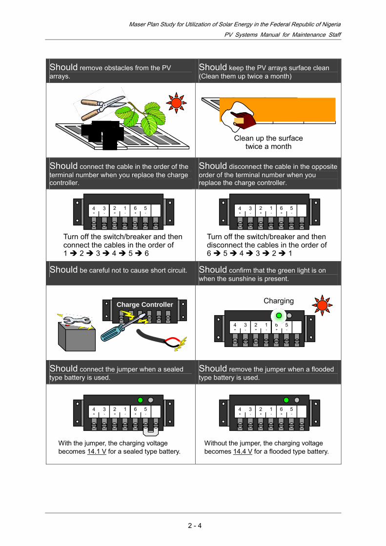
PV systems consist of PV modules, inverters, batteries, and other components. To get needed voltage and current for a particular application, PV modules are connected in series and parallel to compose an array. The system is categorized either grid-connected system or stand-alone system. As is shown in Fig. 3-1, the grid-connected system can provide the load with electricity by both the PV module and grid. The system is used for a large system with capacity of a few kilowatts, and the surplus energy generated by the PV module will be sold to the utility company. Meanwhile, the stand-alone system is generally used in rural and remote areas where no distribution line exists. In order to provide power when the PV module generates no electricity, the system is equipped with the battery.
Grid-connected System
AC Load
GridInverter PV Diode
DC Load
Battery
Inverter
PV Diode
Stand-alone System
AC Load
CC CC: Charge Controller
Fig. 3-1 Configuration of PV Systems
(2) Key Components of PV Systems
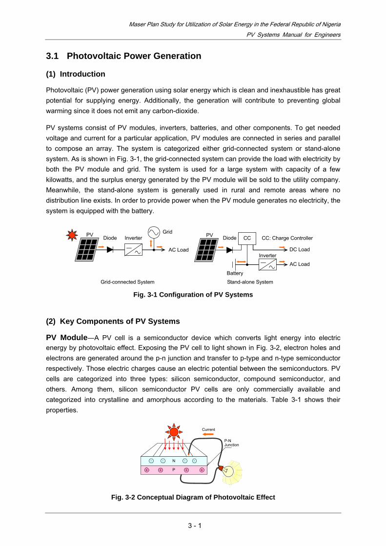
PV Module―A PV cell is a semiconductor device which converts light energy into electric energy by photovoltaic effect. Exposing the PV cell to light shown in Fig. 3-2, electron holes and electrons are generated around the p-n junction and transfer to p-type and n-type semiconductor respectively. Those electric charges cause an electric potential between the semiconductors. PV cells are categorized into three types: silicon semiconductor, compound semiconductor, and others. Among them, silicon semiconductor PV cells are only commercially available and categorized into crystalline and amorphous according to the materials. Table 3-1 shows their properties.
-
P-N Junction
P
N- - -
+ + + +
Current
Fig. 3-2 Conceptual Diagram of Photovoltaic Effect
3 - 1

Maser Plan Study for Utilization of Solar Energy in the Federal Republic of Nigeria PV Systems Manual for Engineers
Table 3-1 Properties of Silicon Semiconductor PV Cells
Type Item Monocrystal Polycrystal Amorphous
Conversion Efficiency 14 - 15% 11 - 13% 6 - 9%
Advantage Widely used High production volume
Cost reduction available
Disadvantage High cost High cost Likely deteriorate
A PV module consists of tens of PV cells in series to get proper voltage for electrical appliances. As is shown in Fig. 3-3, PV cells are enclosed with Ethylene-Vinyl Acetate (EVA), and the semiconductors are connected with ribbon wirings. Furthermore, the cells filled with EVA resin are sandwiched between a front cover (reinforced-glass made) and back cover (film made), and rimmed with an aluminum frame.
PV Cell WiringFront Cover
AluminumFrame
Sealing Material
Filling Material
Back Cover
Fig. 3-3 Configuration of PV Module
The Fig. 3-4 shows a nameplate of PV module with capacity of 165 watt. The electrical characteristics is tested under the Standard Test Condition (STC) in accordance with IEC 60904-1―irradiance of 1000 W/m2 with IEC 60904-3 reference solar spectral irradiance distribution, air mass (AM) 1.5 spectrum and cell temperature of 25 degrees. In addition, AM is defined as the ratio between the path length of perpendicular incidence and that of direct incidence as shown in Fig. 3-5. The electrical characteristics―Maximum power, open circuit voltage, short circuit current, maximum power voltage, and maximum power current―is greatly influenced by the condition of irradiance and cell temperature. As is shown in Fig. 3-6, the current I is maintained virtually constant against the voltage V until V gets at the maximum power voltage Vpm. In other words, PV modules function as constant current sources.
Atmospheric boundary
Ground θ
AM1
AM = 1/ sinθ
Fig. 3-4 Nameplate of PV Module Fig. 3-5 Definition of Air Mass
3 - 2

Maser Plan Study for Utilization of Solar Energy in the Federal Republic of Nigeria PV Systems Manual for Engineers
Voc
I
Fig. 3-6 Electrical Characteristics of PV Module
Storage Battery―For PV system applications, lead batteries are widely used because they have a large capacity and are moderate-priced. Lead batteries are roughly classified into cycle and trickle use. A PV system repeats the cycles of charging electricity generated by the PV modules in the daytime and discharging it in the night. In general, batteries used for automobiles and Uninterruptible Power Supply (UPS) are float-charged at a constant voltage, and they are not appropriate for deep discharge―i.e. Depth of Discharge (DOD) * is large―and the repeating of charge and discharge. Consequently, in the event that batteries for trickle use are applied to the PV systems, there is possibility that the lifetimes of the batteries remarkably fall. Fig. 3-7 indicates the examples of battery discharge characteristics for trickle use with the depth of discharges as a parameter.
* Ratio of the amount of electric discharge against rated capacity
Fig. 3-7 Battery Discharge Characteristics
Fig. 3-8 shows a configuration of vented type battery. The negative and positive electrodes consist of expanded lead alloy filled with pasty lead powder. The active material for positive electrode is lead dioxide, while spongiform lead is used for the negative electrode. The separator prevents the electrodes from short circuit, and the glass mat is used to hold active materials on the electrodes.
Isc P
Isc
Voc
Pm
Voc and Isc – irradiance characteristics I and P – V characteristics Pm, Voc, and Isc – cell temperature characteristics
Dis
char
ge C
apac
ity [%
]
120
100
80
60
40
20
0 200 400 600 800 1000 1200 1400
Number of Discharge [cycle]
DOD = 100%
50% 30%
3 - 3

Maser Plan Study for Utilization of Solar Energy in the Federal Republic of Nigeria PV Systems Manual for Engineers
Vent PlugLid
Terminal
Upper Level
Lower Level
Negative Electrode
Separator
Glass Mat
Strap Case
Saddle Positive Electrode
Fig. 3-8 Configuration of Vented Type Battery
Dilute sulfuric acid is used for the electrolyte. The chemical equation of the charge and discharge is expressed as follows:
PbO2 + 2H2SO4 + Pb discharge Pb SO4 + 2H2O + Pb SO4 (1) PbO2 + 2H2SO4 + Pb charge Pb SO4 + 2H2O + Pb SO4
The specific gravity of electrolyte indicates the State of Charge (SOC) of the battery. Using a hydrometer, the specific gravity can be measured as shown in Fig. 3-9. Using the following equation, the measured value can be converted to the standard value at 20℃.
SG20 = SGt + 0.0007 (t-20) (2)
Where, SG20 : Specific Gravity at 20 ℃ , SGt : Specific Gravity at t ℃ , t : Electrolyte Temperature―using ambient temperature in practice. Finally, the converted value indicates the SOC of the battery as shown in Table 3-2. Note that the SG20 varies depending on the battery and electrolyte.
1.270 1.120
Float
Fig. 3-9 Measuring Method of Specific Gravity
Table 3-2 Example of Specific Gravity-State of Charge Characteristics at 20℃
Specific Gravity State of Charge [%]
1.280 100 1.240 75 1.200 50 1.160 25 1.120 0
3 - 4

Maser Plan Study for Utilization of Solar Energy in the Federal Republic of Nigeria PV Systems Manual for Engineers
Fig 3-10 shows a Valve Regulated Lead Acid (VRLA) battery―i.e. sealed type batteries. The VRLA battery contains small amount of electrolyte. Since the battery is sealed, it can be laid down. Fig. 3-11 shows the principal of the sealing means. Oxygen gas which is generated in the negative electrode at late stage of charge is absorbed by the spongiform lead of the electrode, and the gas is consumed inside the battery.
Early Stage of Charge Late Stage of Charge
Charger Charger
Positive Electrode
Negative Electrode
Positive Electrode
Negative Electrode
Fig. 3-10 VRLA Battery Fig. 3-11 Sealing Means of VRLA Battery
The capacity of a battery is a product of discharge current and time―Ampere-hour. When a battery is discharged at a constant current I for discharge time of t hours until the voltage V descends to the discharge termination voltage, the value of current is defined as an hour rate and expressed as (1/ t) C discharge. The hour rate capacities vary in accordance with the discharging currents. As shown in Fig. 3-12, the more discharge current becomes, the lower the discharge termination voltage turns out.
13
1 2 3 4 5 6
12
11
10
9
80
Discharge Time [hour]
Volta
ge [V
] 0.2 C
10.2V
9.3V
8.4V
0.65 C
1C
Fig. 3-12 Discharge Characteristics of Lead Acid Battery
Charge Controller and Inverter―A charge controller is used to control the battery charging by monitoring the battery voltage. Most controllers use Pulse-Width Modulation (PWM) control and automatically connect and disconnect the battery and load by semiconductor switches.
Fig. 3-13 Charge Controller
3 - 5

Maser Plan Study for Utilization of Solar Energy in the Federal Republic of Nigeria PV Systems Manual for Engineers
An Inverter is used to supply AC load with electricity. There are two types of inverters―one is sinewave type and the other is pseudo sinewave type as shown in Fig. 3-14. The sinewave type inverter supply the identical power frequency as the grid and can be used for any electrical appliances. Meanwhile, the pseudo sinewave type can not be used for the loads which operate depending on the wave form such as inverter type fluorescent lumps.
t
Sinewave Type
t
Pseudo Sinewave Type
v v
Fig. 3-14 Conceptual Diagram of Inver
Others―A fuse is used in main circuit of the PV system for preventing electrical appliances from the damage caused by short circuit. Especially, the fuse shall be connected between the battery and charge controller since the battery is easily broken by its short circuit current.
A Molded Case Circuit Breaker (MCCB) is used to switch on and off the circuit. In case of fault, it breaks the fault current after the certain time period in inversely relation to the percentage of fault current.
Percentage of Fault Current [%]
Tirp
Tim
e [s
ec]
Max.
Min.
Fig. 3-15 Fuse for Low Voltage Circuit Fig. 3-16 Operating Characteristics of MCCB
3 - 6

Maser Plan Study for Utilization of Solar Energy in the Federal Republic of Nigeria PV Systems Manual for Engineers
3.2 PV Systems Design
(1) Introduction
Meteorological conditions greatly affect energy outputs of PV systems; however, the detailed data nearby project sites are often not available. In addition, since the installation conditions also have an effect on the energy outputs, the prediction of the energy is hard and difficult. In practice, a PV systems design is carried out by reference to the design of similar systems. Fig. 3-17 shows the flow chart of PV systems design
• Monthly Average Solar Irradiation [kWh/m2-day]
• Ambient Temperature [℃] • System Voltage [V] • Running Days of No Solar
Radiation [day] • Depth of Discharge [%] • Other Conditions―Longitude,
Latitude, Humidity, and Rainfall
Step 1 • Load [W] and Hour of Use [h] • Daily Consumed Ampere-hour [Ah]• Daily Required Ampere-hour [Ah]
Step 2 • Selection of PV Modules • Capacity of Battery [Ah] • Selection of Charge Controller • Selection of Inverter
• Layout of Equipment―Installation Configuration, Cabling and etc.
• Selection of Cables
Study on Prerequisite Conditions Electrical Design Layout Design
Fig. 3-17 Flow Chart of PV Systems Design
(2) Design Parameters
Direction and Tilt angle of PV modules―Since the earth rotates with axial inclination of 23.45 degree, solar irradiances on the ground have seasonal and location variations. Fig. 3-18 illustrates the orbit of the sun in the northern hemisphere. In midsummer, the sun orbits the highest path, while it takes the lowest path in midwinter. Fig. 3-19 shows the solar irradiance variation observed at Hamamatsu city, Japan, with latitude of 34.5 degree. The four curves represent the solar irradiance northward (N), southward (S), eastward (E), and westward (W). As is shown the figure, the southward irradiance becomes the highest. Thus the PV module shall face south to get the maximum solar irradiation. Additionally, the PV module shall be installed considering that no obstacle will shade the modules in midwinter.
S
W E
N
At tilt angle of 30 degree
Sol
ar Ir
radi
ance
[kW
/m2 ]
Time Source: NEDO
Equinoxes
W
E
NS
Midwinter
Midsummer
Fig. 3-18 Orbit of the Sun Fig. 3-19 Solar Irradiance Variation
3 - 7

Maser Plan Study for Utilization of Solar Energy in the Federal Republic of Nigeria PV Systems Manual for Engineers
According to the study in Japan, the optimum tilt angle which provides the maximum annual solar irradiation is slightly smaller than the latitude of the location. In addition, the PV module shall be set up at the tilt angle between 10 and 15 degrees at least to prevent rain water from remaining on the difference in level between their front cover and aluminum frame. Consequently, 15 degrees is recommended as the tilt angle in Nigeria because the country is located between the latitudes of 4 and 14 degree.
Solar Irradiation―Once you obtain the monthly average solar irradiation nearby the site, you have to determine the design value among the data. Being on the safe side, the minimum solar irradiation is recommended to use as the design value.
Ambient Temperature―Since the output of PV modules is greatly affected by the cell temperature, you have to carefully take ambient temperature into consideration. Typically, the output of PV modules will decrease approximately by 20% if the temperature rises by 50 degrees. If any average temperature over 45 degrees is expected at the site, you shall take it for the design value. Otherwise, assume 45 degrees as the design ambient temperature.
System Voltage―For the purpose of reducing the loss caused by the circuit current, the higher system voltage is preferable; however, most commercially available PV system products are designed for 12 V or 24 V use according to the rated voltage of batteries. For Solar Home Systems (SHSs) application, 12 V is suitable as the system voltage because rated power of SHSs is generally in the rage of 100 W. For the lager systems, 24 V or more is recommended as long as the products are available.
Running Days of No Solar Radiation and Depth of Discharge―The batteries supply the loads with electricity while the PV modules do not generate. The required capacity of the batteries is subjected to the running days of no solar radiation and DOD. Typically, 3 days are expected for no solar radiation, while DOD is assumed 50% as the design value.
(3) Design Methods
Study on Prerequisite Conditions―Firstly, determine the following design values:
• Monthly average solar irradiation SIA [kW/m2-day]―the minimum value of monthly average solar irradiations is recommend to use for the design,
• Ambient temperature T [degree]―45 degrees as long as the higher temperature is not expected,
• System voltage Vs [V]―12 V or 24 V,
• Running days of no solar radiation DNSR [day]―3 days, and
• Depth of discharge DOD [%]―50%
And then, collect the other information such as the longitude, latitude, humidity, and rainfall. The information does not directly affects the electrical design of the PV systems; however, you have to confirm whether the rainfall which contributes to the self-cleaning of PV modules is expected or not at the site.
3 - 8

Maser Plan Study for Utilization of Solar Energy in the Federal Republic of Nigeria PV Systems Manual for Engineers
Electrical Design Daily Consumed Ampere-hour
Assume the loads and their hour of use. For AC loads, you have to take a conversion efficiency of inverter into consideration and assume it to be 90%. Dividing the loads by the system voltage, you derive the daily consumed ampere-hour AHC from the quotient.
Daily Required Ampere-hour
Find out the daily required ampere-hour AHR considering the following correction coefficients:
• Correction coefficient of contamination KD
• Correction coefficient of temperature KT
• Correction coefficient of battery circuit KB, and B
• Other correction coefficient KO
KD represents the decrease of PV module outputs caused by the dust on their surface. According to the result of five-point observations in Japan, we assume KD to be 0.98.
KT represents the decrease of PV module outputs caused by the cell temperature rise. Define KT as follows:
KT = 1 + α (T + ΔT - 25) (3)
Where, α[degree-1] : Coefficient of temperature, T [degree] : Ambient temperature, and ΔT [degree] : Temperature rise of PV modules. Assume PV modules outputs decrease by 20% when the temperature rises by 50 degrees and derive α to be - 0.4%/degree. ΔT varies according to the installation configuration of PV modules and is in the range of 18 to 25 degrees. Being on the safe side, assume that ΔT is 25 degrees. When T is 45 degrees, the KT yields 0.82.
KB represents the loss caused by charging and is generally to be 0.80 for lead acid batteries. KB O represents the other losses caused by wiring and charge controllers. Assume that it is 0.90.
Define the product of the above coefficients as the design coefficient as follows:
K = KD・KT・KB・KB O (4)
When T is 45 degrees, K yields 0.58. Dividing the AHC by K, and derive the AHR.
Selection of PV Module
Determine the number of PV modules needed for the system. The PV output current IPV is given by:
IPV = AHR / HSR = AHR / (SIA / 1000) (5)
Where, AHR [Ah/day] : Daily required ampere-hour, SIA [kWh/m2-day] : Average monthly solar irradiation, and HSR [hour/day] : Hours of solar radiation―1000 W/m2 represents the ideal solar irradiance on the ground.
3 - 9

Maser Plan Study for Utilization of Solar Energy in the Federal Republic of Nigeria PV Systems Manual for Engineers
Meanwhile, the PV output voltage VPV is given by:
VPV = VS・KC + ΔVD + ΔVL (6)
Where, VS [V] : System voltage, KC : Coefficient of full-charging, ΔVD [V]: Voltage drop of diode, and ΔVL : Voltage drop of wiring. KC is generally to be 1.24 for lead acid batteries. ΔVD is typically to be 0.7 V, whileΔVL is determined according to the users’ criteria. Referring to standard electrical characteristics of PV modules, you will decide the number and connection of PV modules so as to the PV array output meets the above requirement.
Selection of Battery
The capacity of battery CB is give by: B
CB = AHB C・DNSR / (KL・DOD /100) (7)
Where, AHC [Ah/day] : Daily consumed ampere-hour, DNSR [day] : Running days of No solar radiation, DOD [%] : Depth of discharge, and KL: Coefficient of wiring and controller loss. Assume that KL is 0.9.
Selection of Charge Controller
Considering the charge controllers which are commercially available, decide the number of charge controllers NC first, and then determine the rated input current of IIC and output current IOC as follows:
IIC = IPV / NC (8)
IOC = PM / (VS・NC) (9)
Where, IPV [A] : PV output current , PM [W] : Maximum Load input, VS [V] : System voltage. Confirm that the rated currents of the charge controller meet the above requirement.
Selection of Inverter
Determine the rated output current of IOI and input current III as follows:
IOI = PAC / VAC (10)
III = IOI・VAC / (VS・η) (11)
Where, PAC [W] : AC load input, VAC [V] : AC load voltage, VS [V] : System voltage, and η : conversion efficiency of inverter. We will select the inverters among commercially available product which meet the above requirement. The inverter shall be directly connected to the battery.
According to the type of the AC load, the higher power is required to start up the loads. For example, a color television consumes as 5 times higher power as the rated power when it stars, and a refrigerator needs as 10 times higher power as the rated power when its compressor starts. To determine the rated output of inverters, the above conditions have to be considered. A maximum load input PmI is given by
3 - 10

Maser Plan Study for Utilization of Solar Energy in the Federal Republic of Nigeria PV Systems Manual for Engineers
PmI = Cm・PAC (12)
Where, Cm : Multiple number between maximum load input and rated load input. The output power of the inverter shall meet the above requirement.
Layout Design
Table 3-3 shows rated current associated with voltage drops for PVC cables regulated in Nigeria. In the regulation, total voltage drops between the consumer’s terminals and any points in the installation shall not exceed 2.5% of the nominal voltage. Using the table, you will easily find out the voltage drops which are caused by the current.
Table 3-3 Rated Current associated with Voltage drops for PVC cables
Conductor Enclosed in cable conduit Unenclosed
Cross- sectional
area [mm2]
Number / diameter of wires
Rated current[A]
Voltage drop [mV/A・m]
Rated current[A]
Voltage drop [mV/A・m]
1.0 1/1.13 11 40 13 40 1.5 1/1.38 13 27 27
7/0.50 30 16 30 2.5 1/1.78
7/0.67 18 16 23 16 4 7/0.85 24 10 30 10 6 7/1.04 31 6.8 38 6.8
10 7/1.35 42 4.0 51 4.0 16 7/1.70 56 2.6 63 2.6 25 7/2.14 73 1.6 89 1.6 35 19/1.53 90 1.2 109 1.2
Source: 1996 Electricity Act. Electrical Installation Regulations, Nigeria
(4) Design Example
Table 3-4 shows an example of PV system design. In this example, the stand-alone system having both DC and AC loads is designed.
3 - 11

Maser Plan Study for Utilization of Solar Energy in the Federal Republic of Nigeria PV Systems Manual for Engineers
Tab le 3-4 Example of PV system Design
3 - 12

Maser Plan Study for Utilization of Solar Energy in the Federal Republic of Nigeria PV Systems Manual for Engineers
Maser Plan Study for Utilization of Solar Energy in the Federal Republic of Nigeria PV Systems Manual for Engineers
3 - 13
3 - 13

The Federal Republic of NigeriaMaster Plan Study for Utlization of Solar Energy
Log Book on the
the Pilot Project for Solar PV System
Project Funded by
Operation and Maintenance of
Japan International Cooperation Agency (JICA)
Village: Garkon AlliLocal Government Area: Kiyawa
State: Jigawa

Vill
age:
Gar
kon
Alli
Loc
al G
over
nmen
t Are
a: K
iyaw
aSt
ate:
Jig
awa
Typ
e of
Sol
ar P
V S
yste
m(T
ick
as a
ppro
pria
te):
)So
lar
Hom
e Sy
stem
Nam
e of
Les
see:
___
____
____
____
____
____
____
____
____
____
____
__ID
: ___
____
____
____
____
____
_)
Bat
tery
Cha
rgin
g Sy
stem
Not
e: "
0" d
enot
es sa
mpl
e w
ritin
g.
No.
Dat
eA
mou
nt(N
)Rec
eive
d by
Dat
e of
Bre
akdo
wn
Lam
pW
irin
gSw
itch
Bat
tery
Cha
rge
Con
trol
ler
Sola
rPa
nels
Des
crip
tion
Dat
e of
Act
ion
Tak
en a
nd It
sC
onte
nts
Res
ult
Paym
ent M
ade
for
Rep
airi
ngW
orks
020
07/1
/185
0-
xx
--
-B
roke
n du
ring
the
reno
vatio
n of
the
hous
e
Ass
ista
nce
aske
d to
the
Stat
e G
over
nmen
t for
repa
iring
Afte
r 5 d
ays,
Stat
e G
ov.
sent
eng
inee
rW
iring
: 500
Nai
ra,
Lam
p: 4
00N
aira
Sola
r pan
el w
as st
olen
on
Apr
il/xx
/20x
x
Jan
Feb
Mar
Apr
May
Jun
Jul
Aug Sep
Oct
Nov
Dec
Con
ditio
ns o
f the
Hou
seho
lds a
nd L
ife S
type
that
Aff
ect t
he U
se o
f Sol
ay P
V S
yste
m, C
ompl
aint
s and
Com
men
ts:
Rec
orde
d by
:R
evie
wed
by:
App
rove
d by
:
Log
Boo
k on
the
Ope
ratio
n an
d M
aint
enan
ceof
the
Pilo
t Pro
ject
for
Sola
r PV
Sys
tem
Paym
ent
Rec
ord
on M
aint
enan
ce W
orks
Secu
rity

Mon
thly
Rec
ord
of S
HS
Yea
r:V
illag
e: G
arko
n A
lliL
ocal
Gov
ernm
ent A
rea:
Kiy
awa
Stat
e: J
igaw
a
No.
Mad
eN
ot M
ade
Tot
al A
mou
ntof
Pay
men
t(N
)L
amp
Wir
ing
Switc
hB
atte
ryC
harg
eC
ontr
olle
rSo
lar
Pane
lsN
o. o
fW
orks
No.
of R
espo
nses
mad
e by
the
Stat
eG
over
nmen
t
056
415
90-
21
--
33
Jan
Feb
Mar
Apr
May
Jun
Jul
Aug Sep
Oct
Nov
Dec
Rec
orde
d by
:R
evie
wed
by:
App
rove
d by
:
No
vana
dalis
m th
is m
onth
.
Secu
rity
of t
he S
olar
PV
Sys
tem
No.
of P
aym
ent
Are
a of
Rep
airi
ng W
orks
No.
of M
aint
enan
ce W
orks

Rev
enue
Yea
r___
____
____
____
____
_V
illag
e: G
arko
n A
lliL
ocal
Gov
ernm
ent A
rea:
Kiy
awa
Stat
e: J
igaw
a
No.
Mad
eN
ot M
ade
Rem
uner
atio
n(N
)
056
410
,000
10,0
00
Jan
Feb
Mar
Apr
May
Jun
Jul
Aug Sep
Oct
Nov
Dec
Rec
orde
d by
:R
evie
wed
by:
Rev
enue
Des
crip
tion
Tot
al A
mou
ntC
olle
cted
this
mon
th (N
)
Tot
al C
umul
ativ
eA
mou
nt to
dat
e(N
)
Tot
al A
mou
nt S
pent
for
Mai
nten
ance
Wor
ks (N
)
Spen
ding
Bal
ance
to D
ate
(N)
36,4
0036
,400
1,59
0

Mon
thly
Rec
ord
of B
CS:
Mon
th__
____
____
____
____
__, 2
006
Vill
age:
Gar
kon
Alli
Loc
al G
over
nmen
t Are
a: K
iyaw
aSt
ate:
Jig
awa
Seri
al N
o.of
Bat
tery
Con
ditio
nsof
Bat
tery
(wat
er,
etc.
)
Dat
e. o
fC
harg
ing
Tot
al N
o.of
Bat
tery
Cha
rgin
gof
the
Mon
th
Ext
raPa
ymen
t(N
) *
Cha
rgin
g Pl
ugW
irin
gSw
itch
Bat
tery
Cha
rge
Con
trol
ler
Sola
rPa
nels
Sam
ple
Wri
ting
(No.
)G
ood
Jan/
5, 1
5,25
3-
--
Get
ting
loos
e-
--
BC
S 01
BC
S 02
BC
S 03
BC
S 04
BC
S 05
BC
S 06
BC
S 07
BC
S 08
BC
S 0
9B
CS
10B
CS
11B
CS
12B
CS
13B
CS
14B
CS
15B
CS
16B
CS
17B
CS
18B
CS
19B
CS
20N
ote:
* -
Paym
ent i
mpo
sed
on e
xces
sive
cha
rgin
g.
Rec
orde
d by
:R
evie
wed
by:
App
rove
d by
:
BC
SH
ouse
No.
Des
crip
tions
Indi
vidu
al B
atte
ry C
harg
ing
Wor
ksM
aint
enan
ce W
orks
of B
atte
ry C
harg
ing
Stat
ion

Data Sheet for Charging Record
BCS Charging Record Month
No. Date / Voltage Record 1 Record 2 Record 3 Record 4 Record 5 Record 6 Record 7 Record 8 Remarks
1 Before Charging / / / / / / / /
After Charging / / / / / / / /
2 Before Charging / / / / / / / /
After Charging / / / / / / / /
3 Before Charging / / / / / / / /
After Charging / / / / / / / /
4 Before Charging / / / / / / / /
After Charging / / / / / / / /
5 Before Charging / / / / / / / /
After Charging / / / / / / / /
6 Before Charging / / / / / / / /
After Charging / / / / / / / /
7 Before Charging / / / / / / / /
After Charging / / / / / / / /
8 Before Charging / / / / / / / /
After Charging / / / / / / / /
9 Before Charging / / / / / / / /
After Charging / / / / / / / /
10 Before Charging / / / / / / / /
After Charging / / / / / / / /
11 Before Charging / / / / / / / /
After Charging / / / / / / / /
12 Before Charging / / / / / / / /
After Charging / / / / / / / /
13 Before Charging / / / / / / / /
After Charging / / / / / / / /
14 Before Charging / / / / / / / /
After Charging / / / / / / / /
15 Before Charging / / / / / / / /
After Charging / / / / / / / /
16 Before Charging / / / / / / / /
After Charging / / / / / / / /
17 Before Charging / / / / / / / /
After Charging / / / / / / / /
18 Before Charging / / / / / / / /
After Charging / / / / / / / /
19 Before Charging / / / / / / / /
After Charging / / / / / / / /
20 Before Charging / / / / / / / /
After Charging / / / / / / / /
Before Charging / / / / / / / /
After Charging / / / / / / / /
Before Charging / / / / / / / /
After Charging / / / / / / / /
Before Charging / / / / / / / /
After Charging / / / / / / / /
Example of filling out the data sheetNo. Date / Voltage Record 1 Record 2 Record 3 Record 4 Record 5 Record 6 Record 7 Record 8 Remarks
1 Before Charging 1 / 12.0 V 6 / 12.5 V 10 / 12.0 V 17 / 11.8 V 22 / 12.0 V 27 / 12.5 V / / Filling the battery with
After Charging 2 / 14.5 V 7 / 14.0 V 12 / 14.5 V 18 / 14.5 V 23 / 14.0 V 28 / 14.5 V / / distilled water on 22nd.

Data Sheet for Charging Record
BCS No. Month
Weather 1. Sunny , 2. Cloudy , 3. Rainy , 4. Occasionally rainy , 5. Occasionally Cloudy
Load 1. Lighting 1 , 2. Lighting 2 , 3. Radio , 4. Others (Indicate it in the remarks)
Energy Consumption Record
Date Weather Record 1 Record 2 Record 3 Record 4 Record 5 Remarks
Load From To Load From To Load From To Load From To Load From To
1
2
3
4
5
6
7
8
9
10
11
12
13
14
15
16
17
18
19
20
21
22
23
24
25
26
27
28
29
30
31
Example of filling out the data sheetEnergy Consumption Record
Date Weather Record 1 Record 2 Record 3 Record 4 Record 5 Remarks
Load From To Load From To Load From To Load From To Load From To
1 1 3 10:00 12:00 1 19:00 21:00 2 19:00 22:00
2 4 4 12:00 14:00 1 15:00 16:00 1 19:00 23:00 B/W TV, 30W
Data Sheet for Charging Record
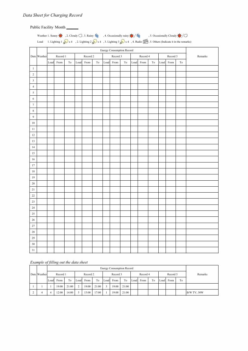
Public Facility Month
Weather 1. Sunny , 2. Cloudy , 3. Rainy , 4. Occasionally rainy , 5. Occasionally Cloudy
Load 1. Lighting 1 , 2. Lighting 2 , 3. Lighting 3 , 4. Radio , 5. Others (Indicate it in the remarks)
Energy Consumption Record
Date Weather Record 1 Record 2 Record 3 Record 4 Record 5 Remarks
Load From To Load From To Load From To Load From To Load From To
1
2
3
4
5
6
7
8
9
10
11
12
13
14
15
16
17
18
19
20
21
22
23
24
25
26
27
28
29
30
31
Example of filling out the data sheetEnergy Consumption Record
Date Weather Record 1 Record 2 Record 3 Record 4 Record 5 Remarks
Load From To Load From To Load From To Load From To Load From To
1 1 1 19:00 21:00 2 19:00 21:00 3 19:00 21:00
2 4 4 12:00 14:00 5 15:00 17:00 1 19:00 21:00 B/W TV, 30W
x 4 x 4 x 4

Data Sheet for Charging Record
SHS No. Month
Weather 1. Sunny , 2. Cloudy , 3. Rainy , 4. Occasionally rainy , 5. Occasionally Cloudy
Load 1. Lighting 1 , 2. Lighting 2 , 3. Radio , 4. Others (Indicate it in the remarks)
Energy Consumption Record
Date Weather Record 1 Record 2 Record 3 Record 4 Record 5 Remarks
Load From To Load From To Load From To Load From To Load From To
1
2
3
4
5
6
7
8
9
10
11
12
13
14
15
16
17
18
19
20
21
22
23
24
25
26
27
28
29
30
31
Example of filling out the data sheetEnergy Consumption Record
Date Weather Record 1 Record 2 Record 3 Record 4 Record 5 Remarks
Load From To Load From To Load From To Load From To Load From To
1 1 3 10:00 12:00 1 19:00 21:00 2 19:00 22:00
2 4 4 12:00 14:00 1 15:00 16:00 1 19:00 23:00 B/W TV, 30W

Data Sheet for Charging Record
Spare Parts and Lending Goods
No. Item Specification Unit Remaining Quantities Remarks
Initial Jan. Feb. Mar. Apr. May Jun. Jul. Aug. Sept. Oct. Nov. Dec.
1. Spare Parts for BCS
1.1 Battery Charger 12 V, 20 A pcs 1
1.2 Charge Controller 12 V, 6 A pcs 1
1.3 Storage Battery 88 Ah, vented type, trickle use pcs 2
1.4 Circuit Breaker Bipolar, 30 A pcs 1
1.5 ditto Bipolar, 20 A pcs 1
1.6 ditto Bipolar, 10 A pcs 2
1.7 Lighting 12 V, 15 W, fluorescent lamp pcs 22
1.8 Switch Bipolar, DC 12 V pcs 10
1.9 Outlet DC 12V pcs 5
1.10 Distilled Water 20 liter pcs 1
2. Spare Parts for Public Facility
2.1 Charge Controller 12 V, 20 A pcs 1
2.2 Circuit Breaker Bipolar, 20 A pcs 1
2.3 Lighting 12 V, 15 W, fluorescent lamp pcs 6
2.4 Switch Bipolar, DC 12 V pcs 1
2.5 Outlet DC 12V pcs 1
3. Spare Parts for SHS
3.1 Charge Controller 12 V, 6 A pcs 2
3.2 Circuit Breaker Bipolar, 10 A pcs 2
3.3 Lighting 12 V, 15 W, fluorescent lamp pcs 40
3.4 Switch Bipolar, DC 12 V pcs 20
3.5 Outlet DC 12V pcs 10
4. Spare Parts for Street Lighting
4.1 Charge Controller 12 V, 10 A pcs 2
4.2 Circuit Breaker Bipolar, 10 A pcs 2
4.3 Lighting 12 V, 18 W, Sodium lamp pcs 5
5. Lending Goods
5.1 Radio 12V, 5W with DC plug pcs 4
5.2 Digital Multimeter Portable pcs 1
5.3 Maintenance Tool Driver, wrench, etc. lot 1
Example of filling out the inventoryNo. Item Specification Unit Remaining Quantities Remarks
Initial Jan. Feb. Mar. Apr. May Jun. Jul. Aug. Sept. Oct. Nov. Dec.
1. Spare Parts for BCS
1.7 Lighting 12 V, 15 W, fluorescent lamp pcs 22 22 20 19 15 10 20 19 18 18 17 Purchase 10 sets of FL in Aug.
5. Lending Goods
5.1 Radio 12V, 5W with DC plug pcs 4 4 4 4 4 4 4 4 4 4 4

Master Plan Study for Utilization of Solar Energy in the Federal Republic of Nigeria
Questionnaire about the Pilot Project State: Jigawa/Ondo/Imo, User: SHS/BCS No. _____
1
1. Attribute a. Name: b. Age: c. Number of family members: Male , Female d. Occupation: □ Employed worker □ self-employed worker □ Farmer □ Others ( ) e. Yearly income f. Number of rooms 2. General 2.1 Are you satisfied with the PV systems? Tick one (1) choice. □ Yes, very much □ Yes, moderately □ No, not much □ No, not at all 2.2 What is the reason of the above answer? Tick one (1) choice. □ Expensive tariff □ Reasonable tariff □ Reliable/Easy to use □ Environmentally friendly 2.3 Do you understand how to use the PV systems? Tick one (1) choice. □ Yes, very well □ Yes, moderately □ No, not well □ No, not at all 2.4 Do you understand that the PV systems have the limitations? Tick one (1) choice. □ Yes, very well □ Yes, moderately □ No, not well □ No, not at all 2.5 Who use the PV systems often? Tick one (1) choice. □ Husband □ Wife □ Children □ Visitors 2.6 From a husband point of view, what did the PV systems improve? Mark the number in order. ( ) Household work ( ) Child care ( ) Reading/ Studying ( ) Security ( ) Income ( ) Saving expenses ( ) Information ( ) Having fun 2.7 From a housewife point of view, what did the PV systems improve? Mark the number in order. ( ) Household work ( ) Child care ( ) Reading/ Studying ( ) Security ( ) Income ( ) Saving expenses ( ) Information ( ) Having fun 2.8 Did you start any business after you started using the PV systems? Tick one (1) choice. □ house industry □ Sewing □ None □ Others ( ) 2.9 How much did you spend for energy (kerosene, battery, etc. ) before you started using the PV systems? Write the monthly amount. 2.10 How much do you spend for energy (kerosene, battery, etc. ) now? Write the monthly amount. 2.11 If possible, how may lighting points do you need? Write the number. 2.12 Which system do you like best? Tick one (1) choice. □ 55 W SHS for two (2) sets of lamps and one (1) radio at the rate of N500/month. □ 110 W SHS for four (4) sets of lamps, one (1) radio, and one (1) TV set at the rate of N750/month. □ 165 W SHS for six (6) sets of lamps, one (1) refrigerator, and one (1) TV set at the rate of N1,000/month.□ BCS for two (2) sets of lamps and one (1) radio at the rate of N50/charge. 2.13 If possible, which appliances do you want to use? Mark the number in order. ( ) Fan ( ) TV set ( ) Refrigerator ( ) Lighting ( ) Others ( ) 2.14 Do you own a generator? Tick (1) one choice and write the output. □ Yes. Output: W □ No 2.15 What appliances do you own? Tick as many as you own. □ Radio □ Fan □ TV set □ Lighting □ Others ( ) 3. Public Facility/Street Lighting 3.1 What do you think Public Facility/Street Lighting? Tick one (1) choice. □ Beneficial □ Not beneficial □Others ( ) 3.2 If possible, how long do you want to use Street Lighting? Tick one (1) choice. □ 4 hours □ 6 hours □ 8 hours □ 10 hours □ 12 hours 3.3 Are you willing to pay tariffs for Public Facility/Street Lighting? Tick one (1) choice. □ Yes, very much □ Yes, moderately □ No, not much □ No, not at all 3.4 What is the reason of the above answer? Tick one (1) choice. □ Beneficial □ Not beneficial □ L.G. shall pay for them □Others ( )

Master Plan Study for Utilization of Solar Energy in the Federal Republic of Nigeria
Questionnaire about the Pilot Project State: Jigawa/Ondo/Imo, User: SHS/BCS No. _____
2
4. SHS *SHS users only4.1 What do you think the monthly tariff of SHS? Tick one (1) choice. □ Inexpensive □ Reasonable □ Expensive 4.2 Considering the charging fee at BCS, which do you prefer, SHS or BCS? Tick one (1) choice. □ SHS □ BCS 4.3 What is the reason of the above answer? Tick one (1) choice. □ Expensive tariff □ Reasonable tariff □ Reluctant to carry the battery □Others ( )5. BCS *BCS users in Jigawa state only5.1 What do you think the charging fee at BCS? Tick one (1) choice. □ Inexpensive □ Reasonable □ Expensive 5.2 Considering the monthly charge of SHS, which do you prefer, SHS or BCS? Tick one (1) choice. □ SHS □ BCS 5.3 What is the reason of the above answer? Tick one (1) choice. □ Expensive tariff □ Reasonable tariff □ Reluctant to carry the battery □Others ( )6. Village Committee 6.1 Does the committee manage the Pilot Project? Tick one (1) choice. □ Yes, very well □ Yes, moderately □ No, not well □ No, not at all 6.2 Does the maintenance staff maintain the PV system properly? Tick one (1) choice. □ Yes, very well □ Yes, moderately □ No, not well □ No, not at all 7. Local Government and State Government 7.1 Do you think the L.G./S.G. contribute to the Pilot Project enough? Tick one (1) choice. □ Yes, very much □ Yes, moderately □ No, not much □ No, not at all 7.2 What do you expect the L.G./S.G. to do? Tick one (1) choice. □ Financial support □ Technical support □Others ( ) 8. Comments on the Pilot Project, if any
Thank you for your cooperation. Signature:

Master Plan Study for Utilization of Solar Energy in the Federal Republic of Nigeria Result of Questionnaire about the Pilot Project
1
1. Attribute
Table 1-1 Number of answers State Number of
objectives Number of answers
Ratio of respondents
Remarks
Jigawa 58 58 100% Excluding 2 systems for schools Ondo 51 46 90% Excluding 9 systems for schools, church, etc. Imo 80 68 85% Total 189 172 91%
Fig. 1-1 Number of family members Fig. 1-2 Occupation
Fig. 1-3 Yearly income (Naira) Fig. 1-4 Number of rooms 2. General
Fig. 2-1 Degree of satisfaction Fig. 2-2 Reason of the degree of satisfaction “Are you satisfied with the PV systems?” “What is the reason of the above answer?”
3
12
4
31
29
13
22
3
18
7
2
9
3
0
4
0
0
4
2
0
5
0% 20% 40% 60% 80% 100%
Imo
Ondo
Jigawa
=< 4 5 - 9 10 - 14 15 - 19 20 - 24 25 - 29 30 <=
6
0
14
8
3
14
35
26
14
9
14
13
0% 20% 40% 60% 80% 100%
Imo
Ondo
Jigawa
Employed Self-employed Farmer Others
40
2
0
19
12
9
5
17
19
0
6
9
0
1
4
0
0
7
0
1
5
0
6
5
0% 20% 40% 60% 80% 100%
Imo
Ondo
Jigawa
< 10.000 10,000 - 50,000 50,000 - 100,000 10,000 - 150,000150,000 - 200,000 200,000 - 250,000 250,000 - 3000,00 300,000 <
9
36
13
37
10
29
12
0
8
10
0
1
0
0
7
0% 20% 40% 60% 80% 100%
Imo
Ondo
Jigawa
=< 4 5 - 9 10 - 14 15 - 19 20 <=
53
42
48
11
1
10
3
0
0
0
0
0
0% 20% 40% 60% 80% 100%
Imo
Ondo
Jigawa
Yes, very much Yes, moderately No, not much No, not at all
56
36
22
7
2
16
4
5
13
1
0
2
0% 20% 40% 60% 80% 100%
Imo
Ondo
Jigawa
Reliable/Easy Reasonable Environmental Expensive

Master Plan Study for Utilization of Solar Energy in the Federal Republic of Nigeria Result of Questionnaire about the Pilot Project
2
Fig. 2-3 How to use the PV systems Fig. 2-4 Limitation of the PV systems “Do you understand how to use the PV systems?” “Do you understand that the PV systems have the limitations?”
Fig. 2-5 Frequent user of the PV systems Fig. 2-6 Business using the PV systems “Who use the PV systems often?” “Did you start any business after you started using the PV systems?”
Fig.2-7 Improvement of living as a husband Fig.2-8 Improvement of living as a housewife “From a husband point of view, what did the PV systems improve?” “From a housewife point of view, what did the PV systems improve?”
Table 2-1 Reduction of energy expense Table 2-2 Number of owners of generator
State Average reduction in Naira
Average reduction ratio
State Number of owners
Jigawa 388 64% Jigawa 2 out of 58 Ondo 458 58% Ondo 2 out of 46 Imo 204 45% Imo 9 out of 68
Average 359 57% Total 13 out of 172
“How much did you spend for energy (kerosene, battery, etc. ) before you “Do you own a generator?” started using the PV systems? How much do you spend for energy now?”
43
44
27
7
1
26
18
0
2
1
0
0
0% 20% 40% 60% 80% 100%
Imo
Ondo
Jigawa
Yes, very well Yes, moderately No, not well No, not at all
31
44
41
10
0
16
28
0
0
0
0
0
0% 20% 40% 60% 80% 100%
Imo
Ondo
Jigawa
Yes, very well Yes, moderately No, not well No, not at all
13
11
55
41
24
3
13
4
0
1
5
0
0% 20% 40% 60% 80% 100%
Imo
Ondo
Jigawa
Wife Husband Children Visitors
29
11
13
9
0
4
31
31
37
0
4
1
0% 20% 40% 60% 80% 100%
Imo
Ondo
Jigawa
House industry Sewing None Others
0% 20% 40% 60% 80% 100%
Imo
Ondo
Jigawa
Household work Child care Reading/Studying SecurityIncome Saving expenses Information Having fun
0% 20% 40% 60% 80% 100%
Imo
Ondo
Jigawa
Household work Child care Reading/Studying SecurityIncome Saving expenses Information Having fun

Master Plan Study for Utilization of Solar Energy in the Federal Republic of Nigeria Result of Questionnaire about the Pilot Project
3
Fig. 2-9 Preferred PV systems “Which system do you like best?”
Fig. 2-10 Preferred electrical appliances Fig. 2-11 Owned electrical appliances “If possible, which appliances do you want to use?” “What appliances do you own?”
Table 2-3 Number of needful lighting points
State Number of lighting points
Jigawa 7
Ondo 3
Imo 7
Average 6
“If possible, how may lighting points do you need?“
3. Public Facility/Street Lighting
Fig. 3-1 Benefit of Public Facility/Street Lighting Fig. 3-2 Hour of use of Street Lighting “What do you think Public Facility/Street Lighting?” “If possible, how long do you want to use Street Lighting?”
6
23
11
29
11
11
32
8
33
0
2
3
0% 20% 40% 60% 80% 100%
Imo
Ondo
Jigawa
55 W SH 110 W SH 165 W SH BCS
Description of PV systems• 55 W SHS for two (2) sets of lamps and one (1) radio at the
rate of N500/month. • 110 W SHS for four (4) sets of lamps, one (1) radio, and one
(1) TV set at the rate of N750/month. • 165 W SHS for six (6) sets of lamps, one (1) refrigerator, and
one (1) TV set at the rate of N1,000/month. • BCS for two (2) sets of lamps and one (1) radio at the rate of
N50/charge.
0% 20% 40% 60% 80% 100%
Imo
Ondo
Jigawa
Fan TV set Refrigerator Lighting Others
66
46
57
1
0
0
0
0
0
0% 20% 40% 60% 80% 100%
Imo
Ondo
Jigawa
Beneficial Not beneficial Others
9
16
0
5
5
0
29
1
0
1
2
0
25
22
58
0% 20% 40% 60% 80% 100%
Imo
Ondo
Jigawa
4 hours 6 hours 8 hours 10 hours 12 hours
45
26
37
30
3
9
45
11
9
25
24
46
13
0
3
0% 20% 40% 60% 80% 100%
Imo
Ondo
Jigawa
Radio Fan TV set Lighting Others

Master Plan Study for Utilization of Solar Energy in the Federal Republic of Nigeria Result of Questionnaire about the Pilot Project
4
Fig. 3-3 Willing to pay for Public Facility/Street Lighting Fig. 3-4 Reason of the willingness to pay “Are you willing to pay tariffs for Public Facility/Street Lighting?” “What is the reason of the above answer?”
4. SHS and BCS
Fig. 4-1 Monthly tariff of SHS Fig. 4-2 Charging fee at BCS “What do you think the monthly tariff of SHS?” “What do you think the charging fee at BCS”
Fig. 4-3 Choice between SHS and BCS Fig. 4-4 Reason of the choice
“Considering the charging fee at BCS, “What is the reason of the above answer?” which do you prefer, SHS or BCS?”
Table 4-1 Tariff of charges (Naira) State Monthly tariff of
SHS Charging fee at
BCS Jigawa 400 30 Ondo 250 ― Imo 350 ―
42
22
4
11
8
10
7
5
7
0
11
34
0% 20% 40% 60% 80% 100%
Imo
Ondo
Jigawa
Yes, very much Yes, moderately No, not much No, not at all
41
28
5
0
0
0
21
17
53
5
0
0
0% 20% 40% 60% 80% 100%
Imo
Ondo
Jigawa
Beneficial Not beneficial L.G. shall pay Others
5
11
15
60
34
9
4
0
15
0% 20% 40% 60% 80% 100%
Imo
Ondo
Jigawa
Inexpensive Reasonable Expensive
11
37
9
0
0% 20% 40% 60% 80% 100%
Jigawa (BCS)
Jigawa (SHS)
SHS BCS
0
0
4
15
10
22
0
0
0% 20% 40% 60% 80% 100%
Jigawa (BCS)
Jigawa (SHS)
Expensive Reasonable Reluctant to carry Others
7 11 1
0% 20% 40% 60% 80% 100%
Jigawa
Inexpensive Reasonable Expensive

Master Plan Study for Utilization of Solar Energy in the Federal Republic of Nigeria Result of Questionnaire about the Pilot Project
5
5. Village Committee
Fig. 5-1 Evaluation of the committee Fig. 5-2 Evaluation of the maintenance staff “Does the committee manage the Pilot Project?” “Does the maintenance staff maintain the PV system properly?”
6. Local Government and State Government
Fig. 6-1 Evaluation of the L.G./S.G. Fig. 6-2 Expectation from the L.G./S.G. “Do you think the L.G./S.G. contribute to the Pilot Project enough?” “What do you expect the L.G./S.G. to do?”
Note)
1) All numbers in the figures show the number of answers which are categorized by the alternatives.
2) In Fig. 1-3, most of the respondents in Imo state answered that their yearly income are below N50,000. However, the result of socio-economic survey shows that their average income are approximately N200,000. Therefore, the respondents do not figure out their income correctly.
3) In Fig. 2-6, not all respondents who answered that they stared business sell products to the others. As a result of the interviews, some respondents started house industry for their private use.
4) In Fig. 2-7, 8, and 10, the answers are weighted based on the priorities since the questionnaires are multiple choices.
58
44
47
8
1
10
0
0
0
1
1
1
0% 20% 40% 60% 80% 100%
Imo
Ondo
Jigawa
Yes, very well Yes, moderately No, not well No, not at all
60
37
53
8
7
3
0
0
0
0
2
0
0% 20% 40% 60% 80% 100%
Imo
Ondo
Jigawa
Yes, very well Yes, moderately No, not well No, not at all
40
24
41
11
20
15
10
1
2
4
1
0
0% 20% 40% 60% 80% 100%
Imo
Ondo
Jigawa
Yes, very much Yes, moderately No, not much No, not at all
53
46
21
4
0
18
1
0
0
0% 20% 40% 60% 80% 100%
Imo
Ondo
Jigawa
Financial Technical Others