TSLM for Walter M601 Engines - VR · PDF fileTSLM - M601 Operational & Install Manual Contents...
33
TSLM for Walter M601 Engines OPERATIONAL & INSTALL MANUAL Updated: 29 June 2016 Copyright 2016 by VR Avionics
Transcript of TSLM for Walter M601 Engines - VR · PDF fileTSLM - M601 Operational & Install Manual Contents...

TSLMfor
Walter M601Engines
OPERATIONAL &INSTALL MANUAL
Updated: 29 June 2016
Copyright 2016 by VR Avionics

TSLM - M601 Operational & Install Manual
© 2016 VR Avionics Inc.All rights reserved.This User and Installation Guide and the information contained herein is the proprietary data of VR Avionics. No part of this manual may be reproduced, copied, transmitted, disseminated or stored in any storage medium, for any purpose without the express written permission of VR Avionics, Inc. VR Avionics hereby grants permission to download a single copy of this manual and of any revision to this manual onto a hard drive or other electronic storage medium to be viewed for personal use, provided that such electronic or printed copy of this manual or revision must contain the complete text of this copyright notice and provided further that any unauthorized commercial distribution of this manual or any revision hereto is strictly prohibited. Information in this document is subject to change without notice. VR Avionics reserves the right to change or improve its products and to make changes in the content without obligation to notify any person or organization of such changes. Visit the VR Avionics website (www.vravionics.com) for current updates and supplemental information concerning the use and operation of this and other VR Avionics products.
VR Avionicswww.vravionics.com
06/29/16 © 2016 VR Avionics page 2 of 33

TSLM - M601 Operational & Install Manual
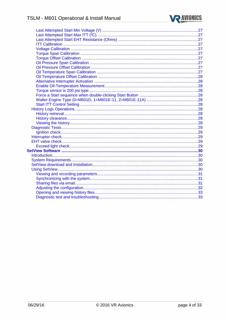
ContentsIntroduction.......................................................................................................................................5
System Options...............................................................................................................................5Retrofit to existing systems.............................................................................................................5TSLM versions................................................................................................................................5
Operation...........................................................................................................................................6Introduction.....................................................................................................................................6Power-up (Master ON)....................................................................................................................6Initiating a Start...............................................................................................................................6Initiating a Run ...............................................................................................................................7Automatic Protection Limiting.........................................................................................................8
Start Limiting...............................................................................................................................8Beta & Reverse Propeller Limiting..............................................................................................8
Anti-Flameout Operation (AFO)......................................................................................................8Determining Engine State...............................................................................................................8Parameter Exceeds........................................................................................................................9
Required Actions........................................................................................................................9TSLM Light Codes..........................................................................................................................9Operational Check Lists and Codes.............................................................................................10Electrical & Mechanical Specifications.........................................................................................11Dimensions (SN 7001 and later)...................................................................................................11Dimensions (SN 5001 – 6200)......................................................................................................12RS232 Data Interface (SN 5001 – 6200)......................................................................................12
Installation.......................................................................................................................................13Tools and Equipment....................................................................................................................13Electrical Installation.....................................................................................................................14Power and Ground........................................................................................................................15Ignition Circuit...............................................................................................................................16Start/Run Selection.......................................................................................................................17Start Contactor..............................................................................................................................17Start Interrupter Valve...................................................................................................................18Limiting (EHT) Circuit....................................................................................................................19TSLM Status Light........................................................................................................................20Exceed Light.................................................................................................................................20Voltage Sensing............................................................................................................................21Gas Generator Speed Sensing (N1).............................................................................................21Propeller Speed Sensing (N2)......................................................................................................21Inter Turbine Temperature Sensing (ITT).....................................................................................22Beta Switch Sensing.....................................................................................................................22Torque and Oil Pressure Sensing (optional)................................................................................23Oil Temperature Sensing (optional)..............................................................................................24TSLM Pin Definitions....................................................................................................................25
Configuration..................................................................................................................................26Introduction...................................................................................................................................26Configuration Settings..................................................................................................................26
History Recorded (bytes)..........................................................................................................26Start Cycles..............................................................................................................................26Flight Hours..............................................................................................................................26Upper ITT Exceeds...................................................................................................................26Lower ITT Exceeds...................................................................................................................26N1 Exceeds .............................................................................................................................26N2 Exceeds .............................................................................................................................26Torque Exceeds .......................................................................................................................27Max. Unit Temperature ºC .......................................................................................................27Min. Unit Temperature ºC ........................................................................................................27Last Attempted Start Time (seconds) ......................................................................................27
06/29/16 © 2016 VR Avionics page 3 of 33
TSLM - M601 Operational & Install Manual
Last Attempted Start Min Voltage (V) ......................................................................................27Last Attempted Start Max ITT (ºC) ..........................................................................................27Last Attempted Start EHT Resistance (Ohms) ........................................................................27ITT Calibration .........................................................................................................................27Voltage Calibration ..................................................................................................................27Torque Span Calibration ..........................................................................................................27Torque Offset Calibration ........................................................................................................27Oil Pressure Span Calibration .................................................................................................27Oil Pressure Offset Calibration ................................................................................................27Oil Temperature Span Calibration ...........................................................................................27Oil Temperature Offset Calibration ..........................................................................................28Alternative Interrupter Activation .............................................................................................28Enable Oil-Temperature Measurement....................................................................................28Torque sensor is 200 psi type..................................................................................................28Force a Start sequence when double-clicking Start Button .....................................................28Walter Engine Type (0=M601D, 1=M601E-11, 2=M601E-11A) ..............................................28Start ITT Control Setting ..........................................................................................................28
History Logs Operations...............................................................................................................28History retrieval.........................................................................................................................28History clearance......................................................................................................................28Viewing the history....................................................................................................................28
Diagnostic Tests...........................................................................................................................29Ignition check............................................................................................................................29
Interrupter check...........................................................................................................................29EHT valve check...........................................................................................................................29
Exceed light check....................................................................................................................29SetView Software ...........................................................................................................................30
Introduction...................................................................................................................................30System Requirements..................................................................................................................30SetView download and Installation...............................................................................................30Using SetView...............................................................................................................................30
Viewing and recording parameters...........................................................................................31Synchronizing with the system.................................................................................................31Sharing files via email...............................................................................................................31Adjusting the configuration.......................................................................................................32Opening and viewing history files.............................................................................................33Diagnostic test and troubleshooting.........................................................................................33
06/29/16 © 2016 VR Avionics page 4 of 33
TSLM - M601 Operational & Install Manual
Introduction
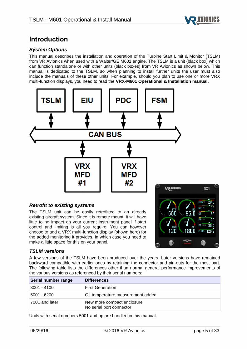
System OptionsThis manual describes the installation and operation of the Turbine Start Limit & Monitor (TSLM) from VR Avionics when used with a Walter/GE M601 engine. The TSLM is a unit (black box) which can function standalone or with other units (black boxes) from VR Avionics as shown below. This manual is dedicated to the TSLM, so when planning to install further units the user must also include the manuals of these other units. For example, should you plan to use one or more VRX multi-function displays, you need to read the VRX-M601 Operational & Installation manual.
Retrofit to existing systemsThe TSLM unit can be easily retrofitted to an already existing aircraft system. Since it is remote mount, it will have little to no impact on your current instrument panel if start control and limiting is all you require. You can however choose to add a VRX multi-function display (shown here) for the added monitoring it provides, in which case you need to make a little space for this on your panel.
TSLM versionsA few versions of the TSLM have been produced over the years. Later versions have remained backward compatible with earlier ones by retaining the connector and pin-outs for the most part. The following table lists the differences other than normal general performance improvements of the various versions as referenced by their serial numbers:
Serial number range Differences
3001 - 4100 First Generation
5001 - 6200 Oil-temperature measurement added
7001 and later New more compact enclosureNo serial port connector
Units with serial numbers 5001 and up are handled in this manual.
06/29/16 © 2016 VR Avionics page 5 of 33

TSLM - M601 Operational & Install Manual
Operation
IntroductionThe following sections describe the working of the TSLM (firmware version 3.1 or later) in detail. Near the end of this chapter we provide the various checklists and error codes on one page for your convenience.
Power-up (Master ON)When first the TSLM is powered it turns on the TSLM light for about 2 seconds while it does a self-check. If everything checks out the TSLM light is turned off. If a problem or concern is detected the TSLM light indicates as follows:
Problem or Concern TSLM light indication
EHT Error:The EHT valve is being powered externally from the TSLM due to possible wiring problem
4 blinks.. pause.. 4 blinks.. pause, etc
Memory Warning:The TSLM memory used for recording start and exceed graphs has reached the 90% mark. You may want to retrieve this history and clear the TSLM's memory.
7 blinks (directly after power-up)
TSLM Internal Fault:The TSLM has failed the self-check and needs to be serviced.
Solidly on or slowly flashing (no code)
Initiating a StartBy depressing the START button you initiate a start sequence. The TSLM performs pre-start checks first unless commanded to bypass them (see later). It checks that the ITT is connected properly and reads below 200ºC, that the bus voltage is at least 20 volt and that the EHT is detected electrically. These checks have been included for safer starting and if one fails the TSLM will decline the start and report the cause via the TSLM light as follows:
Cause of Error TSLM light indication
ITT Error:ITT is above 200ºC or not connected properly. If above 200ºC you may want to do a RUN to cool it down before attempting another start.
2 blinks.. pause.. 2 blinks.. pause, etc.
Voltage Error:The bus voltage is too low for safe starting.
3 blinks.. pause.. 3 blinks.. pause, etc.
EHT Error:Access by the TSLM to the EHT valve could not be confirmed electrically. The reason could be that the limiter enable/disable switch is not in the correct position.
4 blinks.. pause.. 4 blinks.. pause, etc
The pre-start checks can be bypassed by double-clicking the START button. The “double-click start override” setting must be enabled in the TSLM configuration for this to work.
06/29/16 © 2016 VR Avionics page 6 of 33
TSLM - M601 Operational & Install Manual
If one of the pre-start checks failed, you should correct the cause before trying again. To acknowledge or reset the error code on the TSLM light you can press the START or RUN button for 1 second. The TSLM light shall stop flashing and you are ready to issue another start.
If all the pre-start checks pass, the TSLM will activate the start sequence by engaging the starter, turning on the ignition and sequencing the fuel to the torch igniters. You should be able to hear the starter/generator wind up and the igniters producing sparks. From the moment the starter engages there are 10 seconds reserved for light-off. Light-off is where the main fuel in the combustion chamber ignites and can clearly be heard and seen in the ITT rising sharply. In case light-off does not occur within the 10 seconds (which implies some problem), the TSLM will turn off the ignition and stop the fuel to the torch igniters, but continue spinning the engine for 10 more seconds.
If this happens the pilot must close the fuel (shut-off valve lever to closed) just after the first 10 second period have expired. With the engine spinning for the next 10 seconds or so, closing the fuel will purge fuel vapors from the combustion chamber.
If the engine lights off before the first 10 second period expired (as would normally happen), the TSLM will sense this and immediately start controlling the rise in ITT and the absolute ITT value as needed by activating the EHT valve. Both the TSLM light and the EHT light (if fitted) will turn on when the EHT is activated by the TSLM during the start.
If the ITT leads (from the thermocouples) is connected the wrong way around (maybe after a service) or become disconnected in some way that would only become apparent after light-off, the TSLM will sense this and immediately turn on the EXCEED light. Since the TSLM can no longer measure the ITT accurately in this condition, the pilot needs to abort the start by cutting fuel as earlier mentioned to avoid possibly damaging the turbine. The starter will remain active for another 10 seconds so that fuel can again be purged from the combustion chamber.
The EXCEED light will also be turned on when the ITT increases to over 700ºC. The TSLM should be able to control the ITT to below this temperature. If it is unable to, this would imply some major problem – for example unintended isolating valve activation, dead batteries, or fuel control unit problems. An abort of the start is recommended in this case.
When the compressor reaches idle speed (above 50%), the starter, ignition and fuel to the torch igniters will be turned off. Otherwise these devices will timeout 20 seconds after light-off was detected.
See also Determining Engine State.
Initiating a Run A run operation purges possible fuel vapors inside the combustion chamber. If your ITT is above 200ºC performing a run will cool down the turbine temperature by forcing new air through the engine.
By depressing the RUN button you initiate a RUN / MOTOR sequence. The TSLM will turn on the starter for 8 seconds to spin the engine. After the 8 seconds, the starter is turned off. The TSLM will monitor the N1 signal and alert you after the run if no signal was detected from the N1 tach-generator sensor by pulsing the TSLM light as follows:
Caution TSLM light indication
N1 Error:While conducting the run the TSLM did not detect any signal from the N1 sensors. A signal should have been detected. Check wiring.
5 blinks.. pause.. 5 blinks.. pause, etc
If you get the above warning, check your wiring to rectify this. See also Determining Engine State.
06/29/16 © 2016 VR Avionics page 7 of 33
TSLM - M601 Operational & Install Manual
Automatic Protection LimitingThe TSLM provides automatic engine limiting when it restricts fuel to the engine by activating the EHT valve. The EHT light (if installed) will come ON whenever limiting is performed. Limiting is restricted to only the start and beta-propeller speed limiting. Limiting may also be disabled, by an external limiter enable / disable switch (see page 19 for its electrical circuit).
Start LimitingDuring the start process the engine’s temperature (ITT) can be exceeded – more so when it is started without any form of limiting (no activation of the EHT). The amount of limiting required vary according to conditions such as outside air temperature, altitude, battery charge and initial ITT. The TSLM utilizes an algorithm to control both the rate of rise and the absolute value of the inter-turbine temperature (ITT).
If you have forgotten the limiter enable / disable switch (if installed) in the disable position when initiating a start attempt, the TSLM's pre-start checks will detect it, decline the start attempt and inform you via the TSLM light as to the problem. See the section on initiating a start for more.
Beta & Reverse Propeller LimitingTo prevent a propeller exceed in Beta mode as well as to ensure effective reverse thrust application, the TSLM will limit the propeller speed (N2) while in BETA mode. The TSLM knows the propeller is in beta mode by sensing the BETA micro-switch.
Anti-Flameout Operation (AFO)In anti-flameout operation the igniters and ignition fuel valves are continuously activated as a precautionary measure against engine flameout. This mode is manually activated by the pilot when the engine has already been started (is running) by depressing the START switch for at least one second before releasing it. The TSLM status light will light up to indicate that the AFO mode has been entered. To deactivate this mode in-flight, the pilot depresses the RUN switch for at least one second before releasing it. The TSLM status light should go out indicating the anti-flameout mode has been exited. See also Determining Engine State.
Determining Engine StateThe TSLM mainly uses the N1 (NG) parameter to determine whether the engine is running or not-running (above 50% N1 means running and below means not-running). This engine state is important since it impacts the start-run switch functionality. If not-running the start-run switch(es) initiate start and run sequences, while if the engine is running the switch(es) activate and deactivate anti-flameout operation (AFO). This is why proper N1 wiring and signaling to the TSLM is emphasized and why we have a dedicated TSLM light code for N1 error. The TSLM has an alternative to determine engine state if for example N1 become disconnected or the tach-generator ceases to provide an alternating signal. In this alternative (where N1 will read zero) both the ITT and N2 parameters need to be above 400 (400 °C ITT and 400 rpm N2) for the engine state to be considered as running.
06/29/16 © 2016 VR Avionics page 8 of 33
TSLM - M601 Operational & Install Manual
Parameter ExceedsShould any of the engine parameters go over their maximum limits the EXCEED light (if installed) will come ON for the duration of the exceed. During this time all relevant parameters gets recorded versus time and a dedicated counter increments within the TSLM. This information can be viewed in the Configuration and History sections of the SetView software.
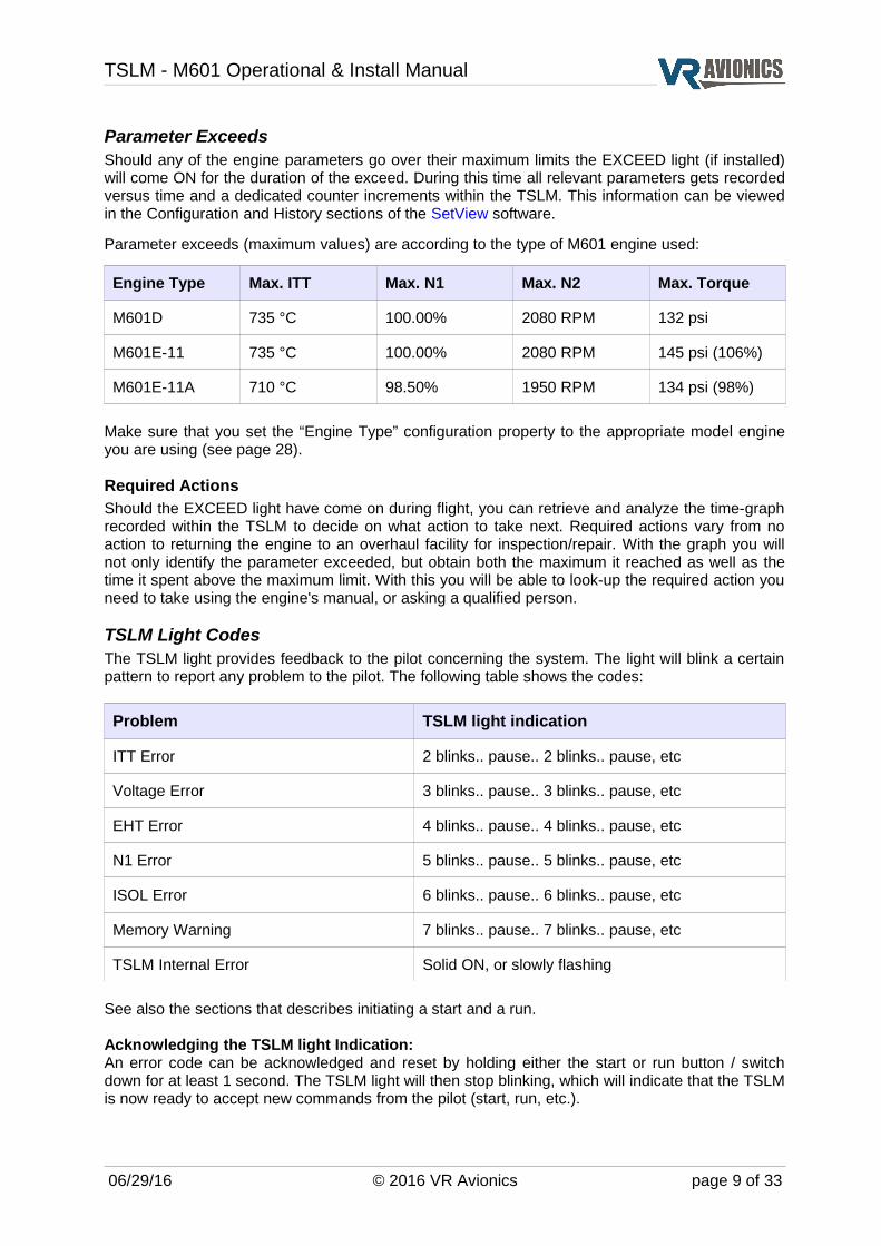
Parameter exceeds (maximum values) are according to the type of M601 engine used:
Engine Type Max. ITT Max. N1 Max. N2 Max. Torque
M601D 735 °C 100.00% 2080 RPM 132 psi
M601E-11 735 °C 100.00% 2080 RPM 145 psi (106%)
M601E-11A 710 °C 98.50% 1950 RPM 134 psi (98%)
Make sure that you set the “Engine Type” configuration property to the appropriate model engine you are using (see page 28).
Required ActionsShould the EXCEED light have come on during flight, you can retrieve and analyze the time-graph recorded within the TSLM to decide on what action to take next. Required actions vary from no action to returning the engine to an overhaul facility for inspection/repair. With the graph you will not only identify the parameter exceeded, but obtain both the maximum it reached as well as the time it spent above the maximum limit. With this you will be able to look-up the required action you need to take using the engine's manual, or asking a qualified person.
TSLM Light CodesThe TSLM light provides feedback to the pilot concerning the system. The light will blink a certain pattern to report any problem to the pilot. The following table shows the codes:
Problem TSLM light indication
ITT Error 2 blinks.. pause.. 2 blinks.. pause, etc
Voltage Error 3 blinks.. pause.. 3 blinks.. pause, etc
EHT Error 4 blinks.. pause.. 4 blinks.. pause, etc
N1 Error 5 blinks.. pause.. 5 blinks.. pause, etc
ISOL Error 6 blinks.. pause.. 6 blinks.. pause, etc
Memory Warning 7 blinks.. pause.. 7 blinks.. pause, etc
TSLM Internal Error Solid ON, or slowly flashing
See also the sections that describes initiating a start and a run.
Acknowledging the TSLM light Indication: An error code can be acknowledged and reset by holding either the start or run button / switch down for at least 1 second. The TSLM light will then stop blinking, which will indicate that the TSLM is now ready to accept new commands from the pilot (start, run, etc.).
06/29/16 © 2016 VR Avionics page 9 of 33
TSLM - M601 Operational & Install Manual
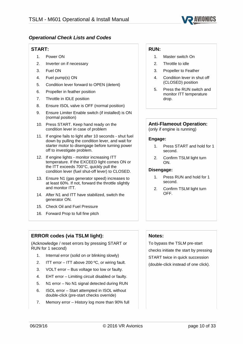
Operational Check Lists and Codes
START:
1. Power ON
2. Inverter on if necessary
3. Fuel ON
4. Fuel pump(s) ON
5. Condition lever forward to OPEN (detent)
6. Propeller in feather position
7. Throttle in IDLE position
8. Ensure ISOL valve is OFF (normal position)
9. Ensure Limiter Enable switch (if installed) is ON (normal position)
10. Press START. Keep hand ready on the condition lever in case of problem
11. If engine fails to light after 10 seconds - shut fuel down by pulling the condition lever, and wait for starter motor to disengage before turning power off to investigate problem.
12. If engine lights - monitor increasing ITT temperature. If the EXCEED light comes ON or the ITT exceeds 700°C, quickly pull the condition lever (fuel shut-off lever) to CLOSED.
13. Ensure N1 (gas generator speed) increases to at least 60%. If not, forward the throttle slightly and monitor ITT.
14. After N1 and ITT have stabilized, switch the generator ON.
15. Check Oil and Fuel Pressure
16. Forward Prop to full fine pitch
RUN:
1. Master switch On
2. Throttle to idle
3. Propeller to Feather
4. Condition lever in shut off (CLOSED) position
5. Press the RUN switch and monitor ITT temperature drop.
Anti-Flameout Operation:(only if engine is running)
Engage:
1. Press START and hold for 1 second.
2. Confirm TSLM light turn ON.
Disengage:
1. Press RUN and hold for 1 second.
2. Confirm TSLM light turn OFF.
ERROR codes (via TSLM light):
(Acknowledge / reset errors by pressing START or RUN for 1 second)
1. Internal error (solid on or blinking slowly)
2. ITT error – ITT above 200 ºC, or wiring fault.
3. VOLT error – Bus voltage too low or faulty.
4. EHT error – Limiting circuit disabled or faulty.
5. N1 error – No N1 signal detected during RUN
6. ISOL error – Start attempted in ISOL without double-click (pre-start checks override)
7. Memory error – History log more than 90% full
Notes:
To bypass the TSLM pre-start
checks initiate the start by pressing
START twice in quick succession
(double-click instead of one click).
06/29/16 © 2016 VR Avionics page 10 of 33

TSLM - M601 Operational & Install Manual
Electrical & Mechanical Specifications
Power Requirements 10 to 32 VDC
Supply Current (start or run sequence) < 10 A
Supply Current (monitoring only) 50 mA
Operating Temperature -40°C to +85°C
Storage Temperature -55°C to +125°C
Dimensions (SN 7001 and later)
Weight 180g (0.4 lb)
Dimensions 100 x 75 x 25mm (3.94" x 2.95" x 0.98")
06/29/16 © 2016 VR Avionics page 11 of 33

TSLM - M601 Operational & Install Manual
Dimensions (SN 5001 – 6200)
Weight 350g (0.772 lb)
Dimensions 150 x 95 x 35mm (5.9" x 3.74" x 1.38")
RS232 Data Interface (SN 5001 – 6200)The TSLM uses a RS232 interface (9600 baud, 8 data-bits, 1 stop-bit, no parity) to link to a Personal Computer, Laptop or similar device. The pins used on the DB-9 port are as follows:
2 – RXD3 – TXD5 – GND
The TSLM will transmit a stream of data 10 times per second out on pin 2. Please contact VR Avionics should you require detailed protocol information.
06/29/16 © 2016 VR Avionics page 12 of 33

TSLM - M601 Operational & Install Manual
Installation
Tools and EquipmentTools and equipment required for installation (not included in the purchase) are:
✔ Wire cutters
✔ Wire strippers
✔ Wire (single core, Teflon insulated 20 AWG)
✔ Thermocouple wire (K-type)
✔ Connector crimp tool
✔ DB-25 female connector with crimp pins
✔ Personal computer running Windows 98 or higher, with a spare serial port. If no serial port,
a USB port together with a USB-to-Serial adapter will do.
✔ Standard RS-232 cable (DB-9 male to DB-9 female)
✔ Torque and Oil Pressure transducers (see page 23)
Description Part Numbers
Crimp contacts M24308/10-1 M39029/63-368 AMP 205090-1
Crimp tool M22520/2-01 AFM8 (DMC)
Crimp tool positioner M22520/2-08 K13-1 (DMC)
Insertion tool MS1969/1-02 DAK 145
Extraction tool MS1969/1-02 DAK 145
06/29/16 © 2016 VR Avionics page 13 of 33

TSLM - M601 Operational & Install Manual
Electrical InstallationThe following section describes the wiring requirements for using the TSLM. Please follow these instructions explicitly as improper wiring can result in permanent damage to your unit. All electrical power and data lines interface with the TSLM via the 25-pin D-Sub connector on the side of the unit. Important Note:
After completing the TSLM system installation, verify it by performing the following tests before you do the first engine start:
➔ Do a Diagnostic Test (Diagnostic Test and Troubleshooting, page 33)
➔ Do a RUN/MOTOR sequence (Run Operation, page 7)
Recommended wiring practices
NOTE: For all electrical connections, use correct splicing techniques, taking care to properly insulate any exposed wire. A short circuit between any of the wires may cause damage to the TSLM and/or other equipment.
VR Avionics does not supply connectors or wire for wiring up your TSLM. We recommend that standard aircraft grade wiring and connectors be used during installation. 20 gauge wire is sufficient for most lines to the unit. Make sure you protect the power lines with either a circuit breaker or fuse sized appropriate to the wire you select. We recommend you use wire meeting Mil Standard MIL-W-22759/16 (Tefzel insulation) which is available from various suppliers. Another option is to use Teflon insulated wire which is available in various colors.
Connectors: We recommend you use machined pin connectors to mate with the TSLM connector. Crimp connections have proven to be the most reliable in aircraft installations. D sub shells to hold the pins are available from various sources. Purchasing quality connectors is a very wise investment.
Installing: Make sure all connections are secure and all wires are routed and strain relieved to ensure the wires will not chafe against any other object in the aircraft.
06/29/16 © 2016 VR Avionics page 14 of 33

TSLM - M601 Operational & Install Manual
Electrical installation of the TSLM system is divided in sections according to function. Sections marked as ‘optional’ are not required for proper operation, but are recommended. The following sections are the minimum requirement:
Power and Ground
Ignition Circuit
Start/Run Selection
Start Interrupter Valve
Start Contactor
Limiting (EHT) Circuit
TSLM Status Light
Exceed Light
Voltage Sensing
Gas Generator Speed Sensing (N1)
Propeller Speed Sensing (N2)
Inter Turbine Temperature Sensing (ITT)
Power and GroundThe maximum current drawn by the TSLM unit is 10 Amps, thus we have to ensure the circuit-breaker and the positive power wire will carry this current. This can be achieved by running one 16 AWG wire into one side of a solder-sleeve and two 20 AWG wires on the other side. The two 20 gauge wires then go to pins 12 and 24 of the TSLM module. The ground wire will not be carrying large current, which means a single 20 AWG wire to pin 13 will be sufficient.
Figure 1 - Power and Ground Wiring
06/29/16 © 2016 VR Avionics page 15 of 33
TSLM - M601 Operational & Install Manual
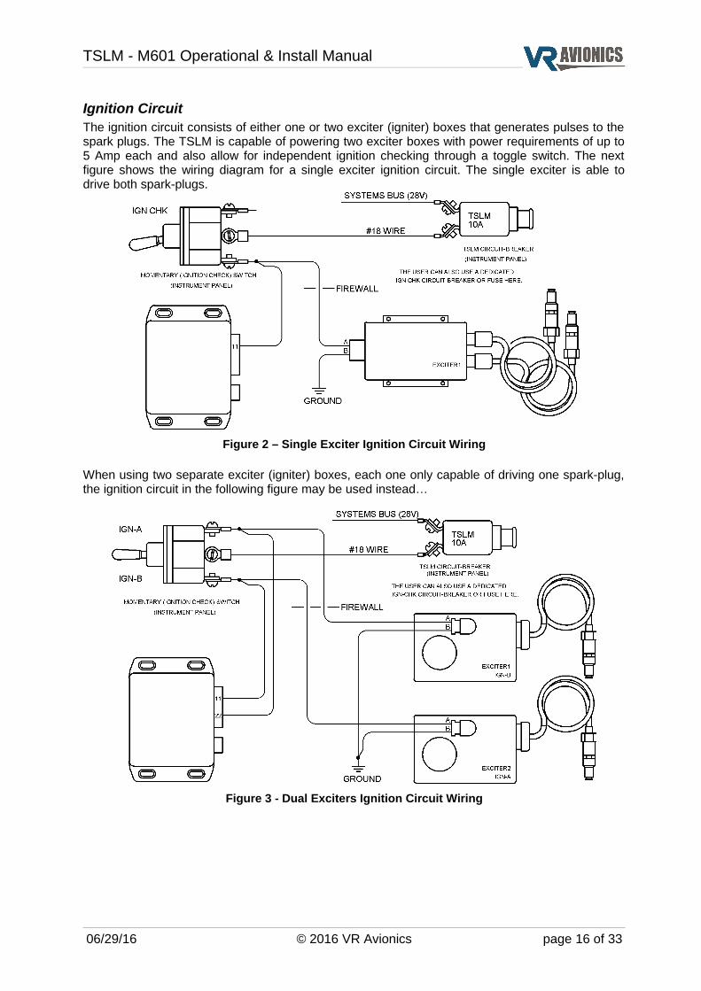
Ignition CircuitThe ignition circuit consists of either one or two exciter (igniter) boxes that generates pulses to the spark plugs. The TSLM is capable of powering two exciter boxes with power requirements of up to 5 Amp each and also allow for independent ignition checking through a toggle switch. The next figure shows the wiring diagram for a single exciter ignition circuit. The single exciter is able to drive both spark-plugs.
Figure 2 – Single Exciter Ignition Circuit Wiring
When using two separate exciter (igniter) boxes, each one only capable of driving one spark-plug, the ignition circuit in the following figure may be used instead…
Figure 3 - Dual Exciters Ignition Circuit Wiring
06/29/16 © 2016 VR Avionics page 16 of 33
TSLM - M601 Operational & Install Manual
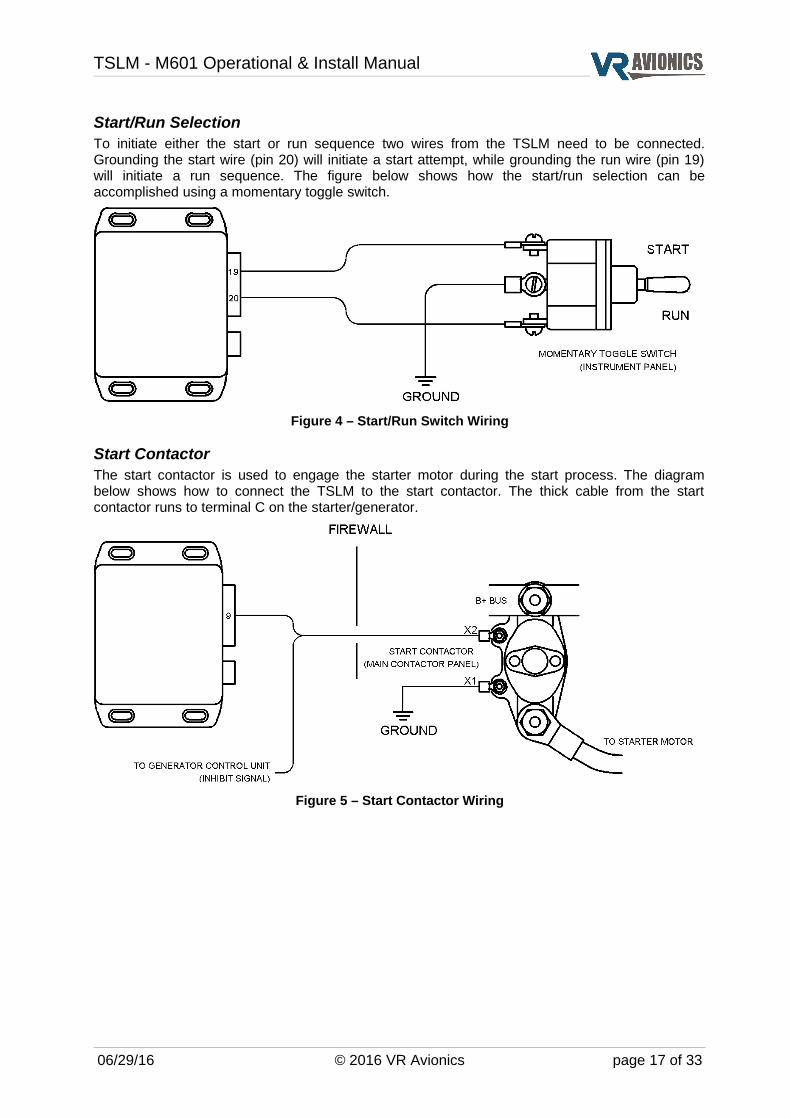
Start/Run SelectionTo initiate either the start or run sequence two wires from the TSLM need to be connected. Grounding the start wire (pin 20) will initiate a start attempt, while grounding the run wire (pin 19) will initiate a run sequence. The figure below shows how the start/run selection can be accomplished using a momentary toggle switch.
Figure 4 – Start/Run Switch Wiring
Start ContactorThe start contactor is used to engage the starter motor during the start process. The diagram below shows how to connect the TSLM to the start contactor. The thick cable from the start contactor runs to terminal C on the starter/generator.
Figure 5 – Start Contactor Wiring
06/29/16 © 2016 VR Avionics page 17 of 33
TSLM - M601 Operational & Install Manual
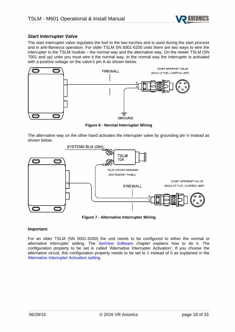
Start Interrupter ValveThe start interrupter valve regulates the fuel to the two torches and is used during the start process and in anti-flameout operation. For older TSLM SN 5001-6200 units there are two ways to wire the interrupter to the TSLM module – the normal way and the alternative way. On the newer TSLM (SN 7001 and up) units you must wire it the normal way. In the normal way the interrupter is activated with a positive voltage on the valve’s pin A as shown below.
Figure 6 - Normal Interrupter Wiring
The alternative way on the other hand activates the interrupter valve by grounding pin V instead as shown below.
Figure 7 - Alternative Interrupter Wiring
Important:
For an older TSLM (SN 5001-6200) the unit needs to be configured to either the normal or alternative interrupter setting. The SetView Software chapter explains how to do it. The configuration property to be set is called ‘Alternative Interrupter Activation’. If you choose the alternative circuit, this configuration property needs to be set to 1 instead of 0 as explained in the Alternative Interrupter Activation setting.
06/29/16 © 2016 VR Avionics page 18 of 33
TSLM - M601 Operational & Install Manual
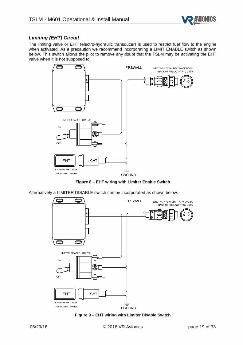
Limiting (EHT) CircuitThe limiting valve or EHT (electro-hydraulic transducer) is used to restrict fuel flow to the engine when activated. As a precaution we recommend incorporating a LIMIT ENABLE switch as shown below. This switch allows the pilot to remove any doubt that the TSLM may be activating the EHT valve when it is not supposed to.
Figure 8 – EHT wiring with Limiter Enable Switch
Alternatively a LIMITER DISABLE switch can be incorporated as shown below.
Figure 9 – EHT wiring with Limiter Disable Switch
06/29/16 © 2016 VR Avionics page 19 of 33
TSLM - M601 Operational & Install Manual
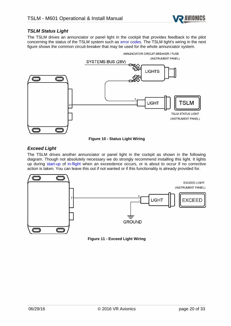
TSLM Status LightThe TSLM drives an annunciator or panel light in the cockpit that provides feedback to the pilot concerning the status of the TSLM system such as error codes. The TSLM light's wiring in the next figure shows the common circuit-breaker that may be used for the whole annunciator system.
Figure 10 - Status Light Wiring
Exceed LightThe TSLM drives another annunciator or panel light in the cockpit as shown in the following diagram. Though not absolutely necessary we do strongly recommend installing this light. It lights up during start-up of in-flight when an exceedence occurs, or is about to occur if no corrective action is taken. You can leave this out if not wanted or if this functionality is already provided for.
Figure 11 - Exceed Light Wiring
06/29/16 © 2016 VR Avionics page 20 of 33

TSLM - M601 Operational & Install Manual
Voltage SensingThe TSLM has to sense the system voltage because low battery voltage can cause start-failures and “hot starts”. The TSLM will decline a start operation when the battery voltage is too low.
Figure 12 - Battery Voltage Sense Wiring
Gas Generator Speed Sensing (N1)The diagram below shows the connection of the N1 tach-generator to the TSLM. The tach-generator signal is strong enough to be shared with other instruments.
Figure 13 - Gas Generator Speed Sense Wiring
Propeller Speed Sensing (N2)The diagram below shows the connection of the N2 tach-generator to the TSLM. The tach-generator signal is strong enough to be shared with other instruments.
Figure 14 - Propeller Speed Sense Wiring
06/29/16 © 2016 VR Avionics page 21 of 33

TSLM - M601 Operational & Install Manual
Inter Turbine Temperature Sensing (ITT)The figure below shows the hookup of the k-type thermocouple wires for ITT. At least within the engine compartment thermocouple cable with metal braiding should be used. Note the ring terminals where the one from the red wire is bigger than the other one.
Figure 15 - Inter-Turbine Temperature Sense Wiring
Sharing thermocouples with a temperature gauge is not a problem. Though thermocouples provide a small signal (millivolts), this signal is strong (low source resistance). The TSLM's thermocouple inputs have both high impedance and a wide common mode voltage range, which ensure accurate but non-intrusive measurement.
Walter M601 type E-11 engines are equipped with 4 ITT wires, 2 for main instrumentation and 2 for an electronic limiting unit. For conformity we recommend connecting the red wire (ITT+) to pin 1 of the TSLM and the green wire (ITT-) to it's pin 14, when installing it on an type E-11 engine.
Beta Switch SensingThe TSLM has an auxiliary input (pin 6) that should be connected to the Beta switch wire. This wire will be grounded when the propeller is in Beta and Reverse. The next diagram shows the practice to follow when using a simple annunciation light system with a press-to-test feature. Employing the diodes as shown below will prevent accidental beta propeller speed limiting when you push the press-to-test button when using this basic annunciation system:
Figure 16 - Beta Sense Wiring
06/29/16 © 2016 VR Avionics page 22 of 33
TSLM - M601 Operational & Install Manual
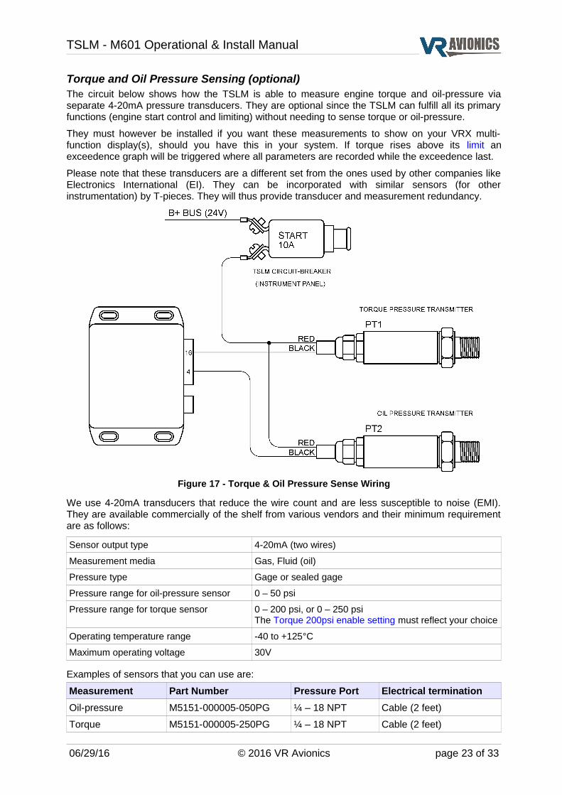
Torque and Oil Pressure Sensing (optional)The circuit below shows how the TSLM is able to measure engine torque and oil-pressure via separate 4-20mA pressure transducers. They are optional since the TSLM can fulfill all its primary functions (engine start control and limiting) without needing to sense torque or oil-pressure.
They must however be installed if you want these measurements to show on your VRX multi-function display(s), should you have this in your system. If torque rises above its limit an exceedence graph will be triggered where all parameters are recorded while the exceedence last.
Please note that these transducers are a different set from the ones used by other companies like Electronics International (EI). They can be incorporated with similar sensors (for other instrumentation) by T-pieces. They will thus provide transducer and measurement redundancy.
Figure 17 - Torque & Oil Pressure Sense Wiring
We use 4-20mA transducers that reduce the wire count and are less susceptible to noise (EMI). They are available commercially of the shelf from various vendors and their minimum requirement are as follows:
Sensor output type 4-20mA (two wires)
Measurement media Gas, Fluid (oil)
Pressure type Gage or sealed gage
Pressure range for oil-pressure sensor 0 – 50 psi
Pressure range for torque sensor 0 – 200 psi, or 0 – 250 psiThe Torque 200psi enable setting must reflect your choice
Operating temperature range -40 to +125°C
Maximum operating voltage 30V
Examples of sensors that you can use are:
Measurement Part Number Pressure Port Electrical termination
Oil-pressure M5151-000005-050PG ¼ – 18 NPT Cable (2 feet)
Torque M5151-000005-250PG ¼ – 18 NPT Cable (2 feet)
06/29/16 © 2016 VR Avionics page 23 of 33
TSLM - M601 Operational & Install Manual
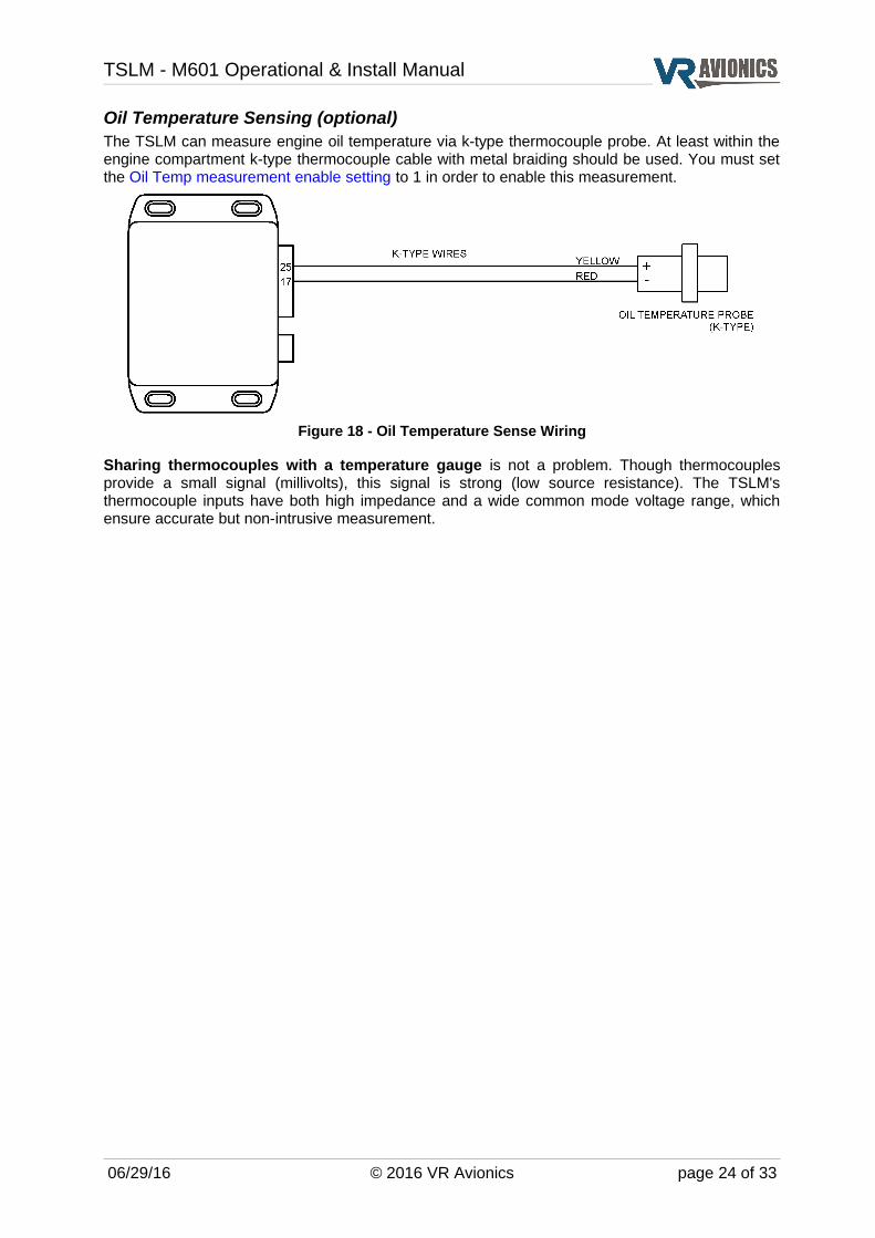
Oil Temperature Sensing (optional)The TSLM can measure engine oil temperature via k-type thermocouple probe. At least within the engine compartment k-type thermocouple cable with metal braiding should be used. You must set the Oil Temp measurement enable setting to 1 in order to enable this measurement.
Figure 18 - Oil Temperature Sense Wiring
Sharing thermocouples with a temperature gauge is not a problem. Though thermocouples provide a small signal (millivolts), this signal is strong (low source resistance). The TSLM's thermocouple inputs have both high impedance and a wide common mode voltage range, which ensure accurate but non-intrusive measurement.
06/29/16 © 2016 VR Avionics page 24 of 33
TSLM - M601 Operational & Install Manual
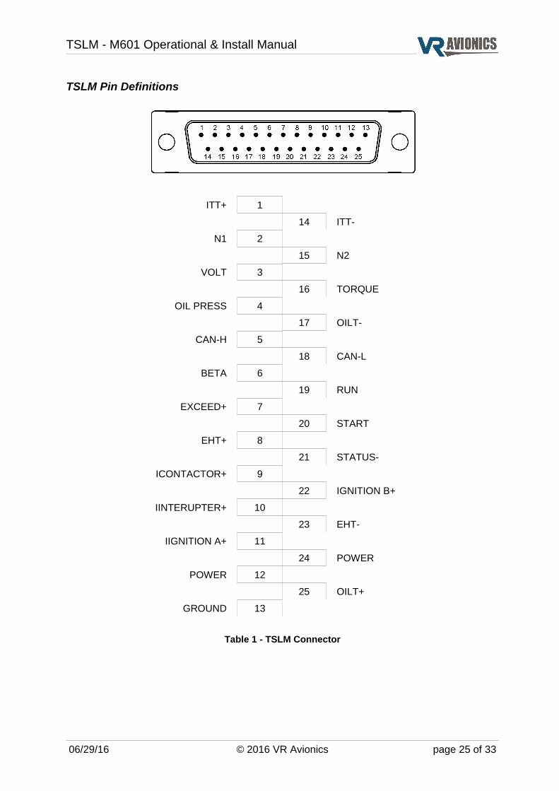
TSLM Pin Definitions
ITT+ 1
14 ITT-
N1 2
15 N2
VOLT 3
16 TORQUE
OIL PRESS 4
17 OILT-
CAN-H 5
18 CAN-L
BETA 6
19 RUN
EXCEED+ 7
20 START
EHT+ 8
21 STATUS-
ICONTACTOR+ 9
22 IGNITION B+
IINTERUPTER+ 10
23 EHT-
IIGNITION A+ 11
24 POWER
POWER 12
25 OILT+
GROUND 13
Table 1 - TSLM Connector
06/29/16 © 2016 VR Avionics page 25 of 33

TSLM - M601 Operational & Install Manual
Configuration
Introduction
This chapter describes the configuration settings of the TSLM, which can be accessed in one of two ways, either:
1) through a Windows computer running our SetView software, or
2) through a VRX multi-function display.
See the SetView Software chapter later in this manual about how to do it through your Windows computer / laptop.
The VRX–M601 Operational & Installation manual (which can be downloaded from our website) describes how to do it through the VRX multi-function display.
Configuration Settings
In this section we describe the various configuration properties of the TSLM. See Adjusting the Configuration about how to alter any of these settings.
History Recorded (bytes)This property tells you how much bytes have been recorded in the TSLM history log.
Start CyclesThis counter tracks the number of start cycles.
Flight HoursThis counter tracks the flight hours (N1 over 70%).
Upper ITT ExceedsThis counter tracks number of times the ITT have exceeded 800 ºC.
Lower ITT ExceedsThis counter tracks the number of times the ITT have exceeded:
M601D 735 ºC
M601E-11 735 ºC
M601E-11A 710 ºC
N1 Exceeds This counter tracks the number of times the N1 have exceeded:
M601D 100.00%
M601E-11 100.00%
M601E-11A 98.50%
N2 Exceeds This counter tracks the number of times the propeller RPM (N2) have exceeded:
M601D 2080 RPM
M601E-11 2080 RPM
M601E-11A 1950 RPM
06/29/16 © 2016 VR Avionics page 26 of 33
TSLM - M601 Operational & Install Manual
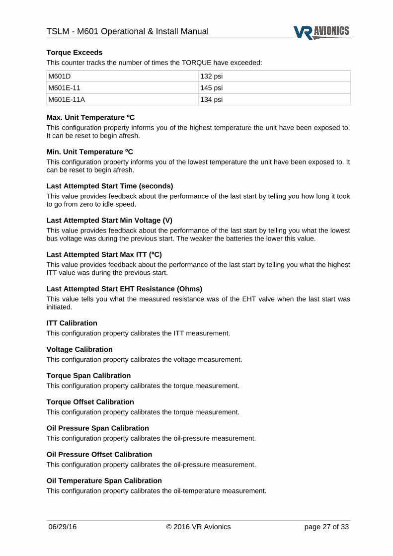
Torque Exceeds This counter tracks the number of times the TORQUE have exceeded:
M601D 132 psi
M601E-11 145 psi
M601E-11A 134 psi
Max. Unit Temperature ºC This configuration property informs you of the highest temperature the unit have been exposed to. It can be reset to begin afresh.
Min. Unit Temperature ºC This configuration property informs you of the lowest temperature the unit have been exposed to. It can be reset to begin afresh.
Last Attempted Start Time (seconds) This value provides feedback about the performance of the last start by telling you how long it took to go from zero to idle speed.
Last Attempted Start Min Voltage (V) This value provides feedback about the performance of the last start by telling you what the lowest bus voltage was during the previous start. The weaker the batteries the lower this value.
Last Attempted Start Max ITT (ºC) This value provides feedback about the performance of the last start by telling you what the highest ITT value was during the previous start.
Last Attempted Start EHT Resistance (Ohms) This value tells you what the measured resistance was of the EHT valve when the last start was initiated.
ITT Calibration This configuration property calibrates the ITT measurement.
Voltage Calibration This configuration property calibrates the voltage measurement.
Torque Span Calibration This configuration property calibrates the torque measurement.
Torque Offset Calibration This configuration property calibrates the torque measurement.
Oil Pressure Span Calibration This configuration property calibrates the oil-pressure measurement.
Oil Pressure Offset Calibration This configuration property calibrates the oil-pressure measurement.
Oil Temperature Span Calibration This configuration property calibrates the oil-temperature measurement.
06/29/16 © 2016 VR Avionics page 27 of 33
TSLM - M601 Operational & Install Manual
Oil Temperature Offset Calibration This configuration property calibrates the oil-temperature measurement.
Alternative Interrupter Activation If set to 0, the interrupter will be normally activated (positive voltage out on pin).If set to 1, the alternative interrupter activation will be employed (pin is grounded).This value defaults to zero for unit serial numbers 7001 and above.See also Start Interrupter Valve circuit.
Enable Oil-Temperature MeasurementSet to 1 if you want the TSLM to measure and share the Oil-temperature with other devices. See also Oil Temperature sensing circuit.
Torque sensor is 200 psi typeSet to 1 if you are using a 200 psi torque sensor instead of the normal 250 psi sensor. See also Torque sensor circuit.
Force a Start sequence when double-clicking Start Button If set to 1, a start sequence can be forced (by bypassing certain pre-start checks) by “double-clicking” the START button / toggle switch. The only check that would not be bypassed is the EHT check. See also Initiating a Start.If set to 0, this feature will be disabled.
Walter Engine Type (0=M601D, 1=M601E-11, 2=M601E-11A) You select the type of M601 engine you have here. This setting is used by the TSLM to know what exceed levels to trigger on. Set to 0 if you have the M601D. Set to 1 if you have the M601E-11. Set to 2 if you have the M601E-11A. See also Parameter Exceeds.
Start ITT Control Setting
This value can be adjusted in the range from 580 to 640. It sets the level of limiting for the start. The lower the value, the lower your start ITT, though your start durations may increase.
History Logs Operations
History retrievalThe TSLM history logs are automatically retrieved when you perform a synchronize through the SetView program. Alternatively these logs can be retrieved via the VRX multi-function display using it's menu to generate a history file on an inserted USB disk (stick).
History clearanceThe history logs are erased from the TSLM memory automatically after a successful retrieval when using the SetView program. On the other hand via the VRX display clearance of the history must be confirmed by the user after a successful retrieval.
Viewing the historyHistory can only be viewed through the SetView software. A history file retrieved onto a USB disk via the VRX display can be opened from within SetView. See also Opening and Viewing History files.
06/29/16 © 2016 VR Avionics page 28 of 33
TSLM - M601 Operational & Install Manual
Diagnostic TestsThrough diagnostic and other tests you can confirm the integrity of your TSLM installation before you do a RUN or a START operation. For additional reading to this section see also Diagnostic Tests through SetView.
Ignition checkTo troubleshoot the ignition circuit this diagnostic test will power the exciter unit(s) through the TSLM. You can now listen for sound, etc.
Interrupter checkTo troubleshoot the interrupter circuit this diagnostic test will toggle the power to the interrupter valve through the TSLM. You can now listen for sound, etc.
EHT valve checkTo troubleshoot the EHT circuit this diagnostic test will toggle the power to the EHT valve through the TSLM. You can now listen for sound, etc. The TSLM will also test for electrical current through the valve.
Exceed light checkTo troubleshoot the Exceed annunciation circuit this diagnostic test will toggle the power to the Exceed light through the TSLM. You can now confirm the light comes on.
06/29/16 © 2016 VR Avionics page 29 of 33
TSLM - M601 Operational & Install Manual
SetView Software
IntroductionThe SetView software connects to older TSLM units to allow you to:
➔ Update firmware
➔ View and record parameters
➔ View and adjust configuration / settings
➔ Retrieve and view history logs
➔ Share history, configuration and recordings via email
➔ Do diagnostic tests for troubleshooting
The new TSLM (serial numbers 7XXX) connect via VRX multi-function display in order to perform the above tasks. For details see the VRX-M601 Operational and Install Manual.
System Requirements➔ Operating System: Windows 7 or higher
➔ One available serial port. If no serial port is available, a USB port together with a USB-to-Serial Converter can be used.
SetView download and InstallationFind the latest version of SetView on our website (www.vravionics.com) and install it onto your Windows computer or laptop:
➔ Click on the SetView Software link found at (www.vravionics.com/downloads.html)
➔ Click on Install and run the setup.exe until all is successfully installed.
Bundled with the latest software are the latest firmware for all VR units in your system (EIU, TSLM, PDC, FSM, etc.). This new firmware may provide new features or have corrected old problems.
Using SetViewThrough its dedicated 9 pin maintenance connector the TSLM can link with your computer / laptop connecting either directly to your computer’s serial port or via a USB-to-Serial converter.
➔ Plug in your USB-to-Serial converter (if you are using one) to your Laptop. If this is the first time it have been plugged into a specific USB port, wait for Windows to recognize it and successfully install its driver.
➔ Connect the USB-to-Serial converter serial port to the 9 pin maintenance connector.
➔ Run the SetView Software.
➔ Select from the main menu System > Serial Port. Confirm you have a COM port selected and that it is the right one.
➔ Power the TSLM module (by switching on the aircraft’s master switch).
Reasons for failing to establish communication could be:
➔ Power was not applied to the TSLM, or
➔ The serial cable between the unit and the laptop is not connected properly, or
➔ The correct serial port was not selected, or
➔ The USB-to-Serial converter driver was not properly installed. If you have bought a new USB-to-Serial converter, you first need to get it to work with Windows on your computer. Plug only the USB-to-Serial converter into the laptop / PC, let Windows recognize it and install the relevant driver first. Only when this is complete and Windows tells you that the device is ready to be used, should you plug it into the TSLM, start the SetView software and switch the power on.
06/29/16 © 2016 VR Avionics page 30 of 33

TSLM - M601 Operational & Install Manual
Viewing and recording parametersAfter running the SetView software, selecting the correct serial port and applying power to the system, the SetView software should start showing the following parameters:
To make a recording select from the main menu System > Record Parameter Stream. To stop recording thereafter select System > Stop Recording Parameter Stream. The recording will then be saved to a file and shown in graph format for you to view.
Synchronizing with the systemBy synchronizing (menu > system > synchronize) SetView will first check the firmware version of
the TSLM and any other VR units in your system (connected via CAN bus). If there is a new
version SetView will in each case ask you if you want to update. Only if you select Yes it will
update the particular unit to the new version.
A synchronize will also make SetView read the TSLM's configuration as well as those for the other
VR units in your system. The bundled configuration settings will be saved to file and can be viewed
by simply clicking on the Config tab at the bottom of SetView.
A synchronize will lastly make SetView retrieve the TSLM history logs and save it to file. The
history can then viewed by simply clicking on the History tab at the bottom of SetView or opened
at a later stage.
Sharing files via emailIf you have made a recording and/or done a synchronize which will read the TSLM configuration,
you can easily share these files with others via email (menu > Share). If troubleshooting and you
require support from VR Avionics, you may email your recording and configuration to us so we can
better be able to assist you.
06/29/16 © 2016 VR Avionics page 31 of 33
TSLM - M601 Operational & Install Manual
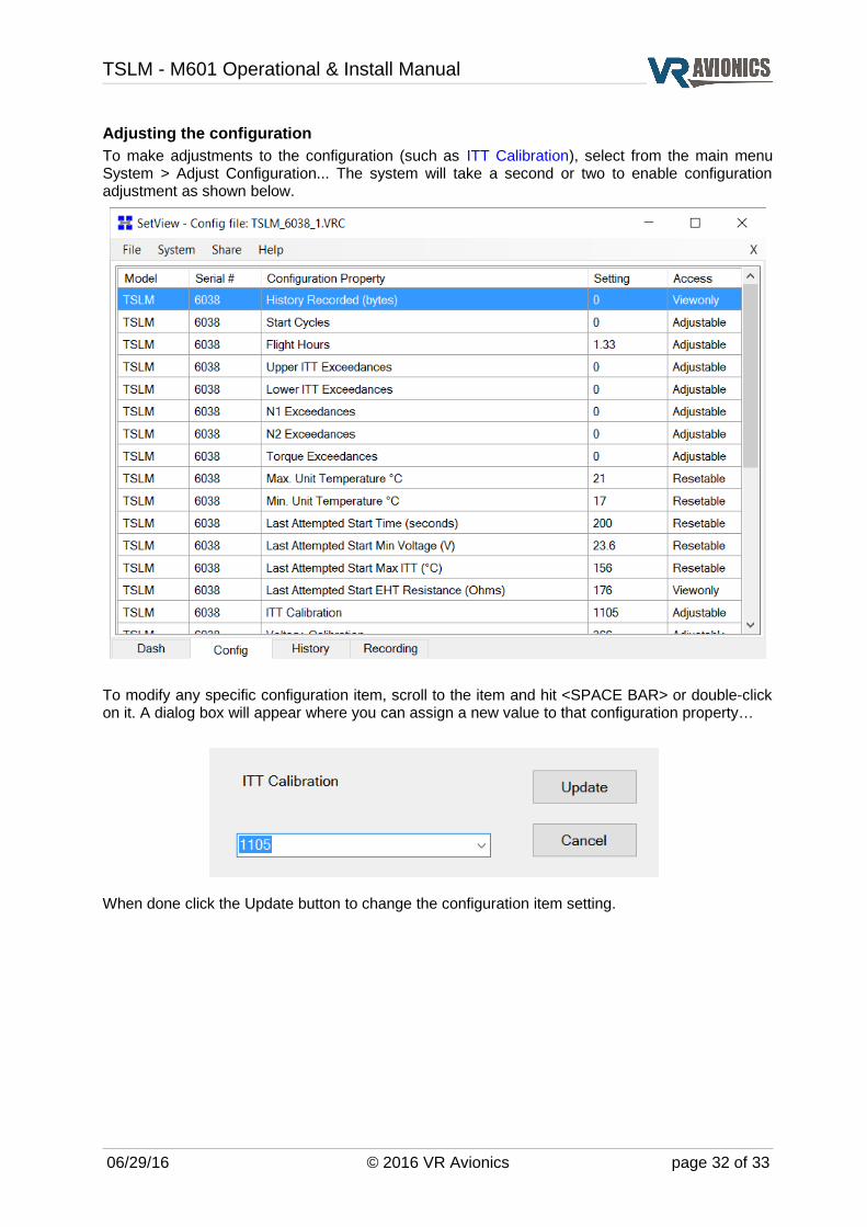
Adjusting the configurationTo make adjustments to the configuration (such as ITT Calibration), select from the main menu System > Adjust Configuration... The system will take a second or two to enable configuration adjustment as shown below.
To modify any specific configuration item, scroll to the item and hit <SPACE BAR> or double-click on it. A dialog box will appear where you can assign a new value to that configuration property…
When done click the Update button to change the configuration item setting.
06/29/16 © 2016 VR Avionics page 32 of 33
TSLM - M601 Operational & Install Manual
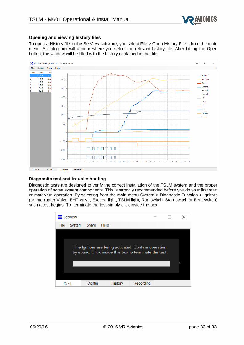
Opening and viewing history filesTo open a History file in the SetView software, you select File > Open History File... from the main menu. A dialog box will appear where you select the relevant history file. After hitting the Open button, the window will be filled with the history contained in that file.
Diagnostic test and troubleshootingDiagnostic tests are designed to verify the correct installation of the TSLM system and the proper operation of some system components. This is strongly recommended before you do your first start or motor/run operation. By selecting from the main menu System > Diagnostic Function > Ignitors (or Interrupter Valve, EHT valve, Exceed light, TSLM light, Run switch, Start switch or Beta switch) such a test begins. To terminate the test simply click inside the box.
06/29/16 © 2016 VR Avionics page 33 of 33