VRX system for the Walter M601 Operational and Installation … · 2016-10-13 · from VR Avionics...
34
VRX system for the Walter M601 Operational and Installation Manual Updated: 13 October 2016 Copyright 2016 by VR Avionics
Transcript of VRX system for the Walter M601 Operational and Installation … · 2016-10-13 · from VR Avionics...

VRX systemfor the
Walter M601
Operationaland
InstallationManual
Updated: 13 October 2016
Copyright 2016 by VR Avionics

VRX - M601 Operational & Install Manual
© 2016 VR Avionics Inc.All rights reserved.This User and Installation Guide and the information contained herein is the proprietary data of VR Avionics. No part of this manual may be reproduced, copied, transmitted, disseminated or stored in any storage medium, for any purpose without the express written permission of VR Avionics, Inc. VR Avionics hereby grants permission to download a single copy of this manual and of any revision to this manual onto a hard drive or other electronic storage medium to be viewed for personal use, provided that such electronic or printed copy of this manual or revision must contain the complete text of this copyright notice and provided further that any unauthorized commercial distribution of this manual or any revision hereto is strictly prohibited. Information in this document is subject to change without notice. VR Avionics reserves the right to change or improve its products and to make changes in the content without obligation to notify any person or organization of such changes. Visit the VR Avionics website (www.vravionics.com) for current updates and supplemental information concerning the use and operation of this and other VR Avionics products.
VR Avionicswww.vravionics.com
10/13/16 © 2016 VR Avionics page 2 of 34
VRX - M601 Operational & Install Manual
ContentsIntroduction.......................................................................................................................................4
System Options..............................................................................................................................4Operation...........................................................................................................................................5
VRX MFD basics............................................................................................................................5Basic soft-keys............................................................................................................................5Removable USB Disk.................................................................................................................6
Annunciation Bar............................................................................................................................6Annunciation list.........................................................................................................................6Alerting operation.......................................................................................................................7
Engine page(s)...............................................................................................................................7SCAN mode................................................................................................................................8Changing Arcs............................................................................................................................8Dual display operation................................................................................................................8
FUEL system page.........................................................................................................................9Fuel adjustment........................................................................................................................10
TSLM system page.......................................................................................................................11TSLM actions and diagnostics..................................................................................................12TSLM history retrieval and erasure..........................................................................................13
EIU system page..........................................................................................................................14FSM system page.........................................................................................................................15PDC system page.........................................................................................................................16Fuel Level Calibrations.................................................................................................................17Flight Data Recording...................................................................................................................18Serial Output Data........................................................................................................................19
Installation.......................................................................................................................................21Mounting the VRD-10...................................................................................................................21
Panel cutout..............................................................................................................................21Mounting the DX1.........................................................................................................................22
Front-of-panel mount................................................................................................................22Rear-of-panel mount.................................................................................................................22
Electrical wiring.............................................................................................................................23Parts and tools..........................................................................................................................23Electrical wiring practices.........................................................................................................23Power and ground....................................................................................................................24Fuel flow circuit.........................................................................................................................24Fuel pressure circuit.................................................................................................................25Emergency ISOL circuit............................................................................................................25CAN bus connection.................................................................................................................26
Configuration..................................................................................................................................28Adjusting the configuration...........................................................................................................28Configuration Password................................................................................................................28VRX-MFD configuration properties...............................................................................................29
Fuel tank identifiers..................................................................................................................30TSLM-M601 configuration properties...........................................................................................31EIU-M601 configuration properties...............................................................................................32PDC configuration properties.......................................................................................................32FSM configuration properties.......................................................................................................33
Updating firmware..........................................................................................................................34Confirming USB disk format.........................................................................................................34Copying files to USB disk.............................................................................................................34Executing the update....................................................................................................................34
10/13/16 © 2016 VR Avionics page 3 of 34

VRX - M601 Operational & Install Manual
Introduction
System OptionsThis manual describes the installation and operation of the VRX multifunction display (or MFD) from VR Avionics when used in a Walter/GE M601 application in either single or dual configuration. There are two models of VRX MFD's, the VRD-10 and the DX1, both running the same firmware. This manual describes version 1.8 operation. These VRX MFD's work with various combinations of VR Avionics line-replaceable units (LRU's) communicating via CAN bus as shown below.
The different LRU's operate independently, though when combined as illustrated the user gains new capabilities and closer interaction. The standalone LRU's have separate manuals describing their installation and operation, and should be used in conjunction with this manual. They may be downloaded from the VR Avionics website.
A second VRX MFD realizes a dual VRX system. This not only provides convenience, but adds redundancy – should one MFD go down, the remaining one can keep on going.
One limitation to the system diagram above does however exists. Should you have both a FSM and EIU in your system, a VRX MFD will only show the system page for one of them. A second VRX MFD in a dual VRX system can however be configured to show the system page left out on the first. See the discussion of system pages later.
Third-party devices and systems may use information acquired via your VRX system. The VRX MFD streams real-time data out on it's serial port. The protocol is the same as that of the EIU-M601 and is described in Serial protocol definition.
10/13/16 © 2016 VR Avionics page 4 of 34
VRX - M601 Operational & Install Manual
Operation
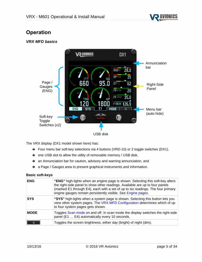
VRX MFD basics
The VRX display (DX1 model shown here) has:
➔ Four menu bar soft-key selections via 4 buttons (VRD-10) or 2 toggle switches (DX1),
➔ one USB slot to allow the utility of removable memory / USB disk,
➔ an Annunciation bar for caution, advisory and warning annunciation, and
➔ a Page / Gauges area to present graphical instruments and information.
Basic soft-keys
ENG “ENG” high-lights when an engine page is shown. Selecting this soft-key alters the right-side panel to show other readings. Available are up to four panels (marked E1 through E4), each with a set of up to six readings. The four primary engine gauges remain persistently visible. See Engine pages.
SYS “SYS” high-lights when a system page is shown. Selecting this button lets you view other system pages. The VRX-MFD Configuration determines which of up to four system pages gets shown.
MODE Toggles Scan mode on and off. In scan mode the display switches the right-side panel (E1 … E4) automatically every 10 seconds.
Toggles the screen brightness, either day (bright) of night (dim).
10/13/16 © 2016 VR Avionics page 5 of 34
USB disk
Soft-keyToggle Switches (x2)
Menu bar(auto hide)
Annunciationbar
Page /Gauges
(ENG)
Right-Side Panel
VRX - M601 Operational & Install Manual
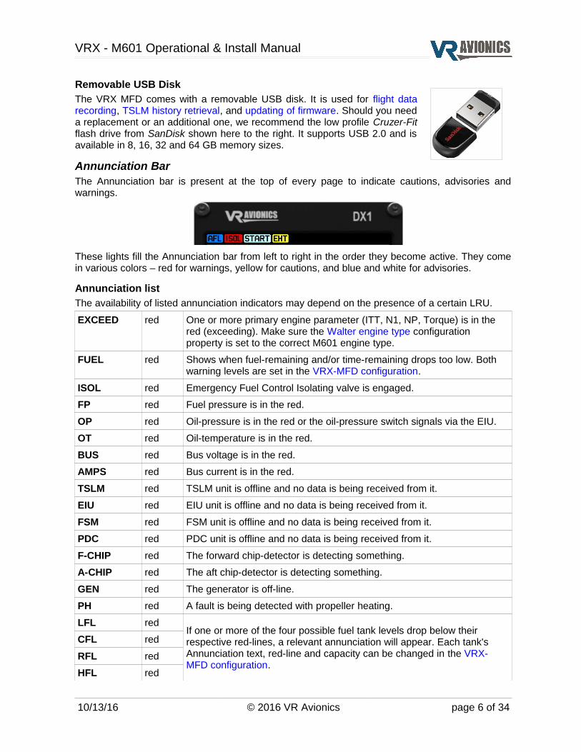
Removable USB DiskThe VRX MFD comes with a removable USB disk. It is used for flight data recording, TSLM history retrieval, and updating of firmware. Should you need a replacement or an additional one, we recommend the low profile Cruzer-Fit flash drive from SanDisk shown here to the right. It supports USB 2.0 and is available in 8, 16, 32 and 64 GB memory sizes.
Annunciation BarThe Annunciation bar is present at the top of every page to indicate cautions, advisories and warnings.
These lights fill the Annunciation bar from left to right in the order they become active. They come in various colors – red for warnings, yellow for cautions, and blue and white for advisories.
Annunciation listThe availability of listed annunciation indicators may depend on the presence of a certain LRU.
EXCEED red One or more primary engine parameter (ITT, N1, NP, Torque) is in the red (exceeding). Make sure the Walter engine type configuration property is set to the correct M601 engine type.
FUEL red Shows when fuel-remaining and/or time-remaining drops too low. Both warning levels are set in the VRX-MFD configuration.
ISOL red Emergency Fuel Control Isolating valve is engaged.
FP red Fuel pressure is in the red.
OP red Oil-pressure is in the red or the oil-pressure switch signals via the EIU.
OT red Oil-temperature is in the red.
BUS red Bus voltage is in the red.
AMPS red Bus current is in the red.
TSLM red TSLM unit is offline and no data is being received from it.
EIU red EIU unit is offline and no data is being received from it.
FSM red FSM unit is offline and no data is being received from it.
PDC red PDC unit is offline and no data is being received from it.
F-CHIP red The forward chip-detector is detecting something.
A-CHIP red The aft chip-detector is detecting something.
GEN red The generator is off-line.
PH red A fault is being detected with propeller heating.
LFL redIf one or more of the four possible fuel tank levels drop below their respective red-lines, a relevant annunciation will appear. Each tank's Annunciation text, red-line and capacity can be changed in the VRX-MFD configuration.
CFL red
RFL red
HFL red
10/13/16 © 2016 VR Avionics page 6 of 34

VRX - M601 Operational & Install Manual
H-PUMP yellow Hydraulic pump signals active via the EIU.
BETA yellow Propeller is in beta mode.
EHT yellow Engine is being limited through the EHT valve.
ITT yellow Problem with the ITT thermocouples and/or wiring to the TSLM.
START white TSLM is busy performing an engine start-up sequence.
PURGE yellow Combustion chamber purging is required. Urges the pilot to move the condition lever to cut-off. Happen if during the start-up sequence the engine failed to light-up in the allotted time.
RUN white Engine run / motor sequence is being performed by the TSLM.
AFO white Anti-Flameout Operation is being performed by the TSLM.
PH blue Propeller Heating is being performed by the PDC.
AFL blue Auto Fuel Leveling is being performed by the FSM.
Alerting operationWith Alerting if primary enabled red indicators (warnings) will begin flashing to draw more attention Alert delay in seconds after becoming active. The pilot can either address the warning by taking corrective action or acknowledge those such as low fuel that have no corrective action. Warnings are acknowledged by selecting the flashing red WARN soft-key. Once acknowledged, the WARN soft-key disappears and the blinking of red indicators halt. If an acknowledged warning disappears such as after successful corrective action, this warning will only Alert again (blinking plus red WARN soft-key) if Repeat acknowledged alerts is enabled and the same warning become active at some later stage.
Engine page(s)The ENG page is the primary page. It shows four circular engine gauges – ITT, N1, TRQ and NP as well as on the right a panel of 6 horizontal slide-gauges. Other right-side panels are available showing further readings and can be accessed via the ENG soft-key:
The readings in E1 through E4 depends on the information the installed LRU's provide. Some measurements have redundancy with two or more LRU's providing the same parameter (eg. N1). In such cases there is a preferred source, but should this source become unavailable the display will automatically switch to the next alternative in line, and so forth.
10/13/16 © 2016 VR Avionics page 7 of 34
E1 E2 E3 E4

VRX - M601 Operational & Install Manual
SCAN modeScan mode automatically toggles the right-side panel every 10 seconds. This mode is activated by selecting the MODE soft-key. The soft-key text changes to SCAN if the mode is engaged. Selecting this SCAN soft-key (again) exits back to the normal mode.
Changing ArcsThe VRX has two sets of red, yellow and greens arcs automatically applied to ITT, N1, BUS voltage and Oil-pressure. One set is for engine start-up, the other for normal in-flight operations.
Dual display operationThe VRX caters for dual display installations whether sharing an instrument panel or mounted on separate panels. The latter typically covers tandem two seat cockpits such as the Turbine Legend.
When sharing an instrument panel one display can be configured to play a secondary role. When powered it starts up with the first system page (typically the FUEL page), while the primary starts up with the first engine page. The secondary will become the primary only if the primary goes offline.
10/13/16 © 2016 VR Avionics page 8 of 34

VRX - M601 Operational & Install Manual
FUEL system pageThe following FUEL system page is available if your VRX system have access to fuel data from either the fuel interface on a VRX display or an EIU or FSM:
It shows the Annunciation bar at the top and the Menu bar at the bottom. A stack of gauges persistent to all system pages lies just below the Annunciation bar. The rest is filled with the following info:
LEFTRIGHTCENTRHEADR
Shows the left, right, center and header fuel tank level(s) measured by level probe(s) in the units for volume (eg. US gallons). Each tank's name, visibility, red-line and capacity can be configured in the VRX-MFD configuration.
F-REM Shows the fuel-remaining value that decreases as fuel flows through the sensor before being consumed inside the engine. This value is set by the pilot to closely resemble the fuel on-board. Also see Fuel adjustment.
F-USED(top row)
Shows the amount of fuel-used since the last fill-up or addition of fuel (fuel adjustment) as metered through the fuel flow sensor.
FLOW(top row)
Shows the flow rate used to calculate time-remaining (next entry in this table). It slightly lags the current fuel flow rate.
TIME-REM(top row)
Shows the time-remaining in hours and minutes until fuel-remaining runs out based on the current fuel flow rate (previous entry in this table).
F-USED(bottom row)
Shows the amount of fuel-used during this flight. A flight begins when N1 reaches the value set by the flight timer start N1 configuration property.
FLOW(bottom row)
Shows the average fuel flow rate during this flight. A flight begins when N1 reaches the value set by the flight timer start N1 configuration property.
TIME-REM(bottom row)
Shows the flight-time in hours, minutes and seconds. A flight begins when N1 reaches the value set by the flight timer start N1 configuration property.
Note: An VRX display must be configured to show this page. See VRX-MFD configuration.
10/13/16 © 2016 VR Avionics page 9 of 34
Menu bar(auto hide)
AnnunciationbarPersistent gauges
(engine primaries)
Flight fuel infoand time

VRX - M601 Operational & Install Manual
Fuel adjustmentTo adjust the fuel-remaining and fuel-used parameters after you have filled-up or added to your fuel on-board, press the MENU soft-key from the FUEL system page as shown below, then select one of three options. Selecting MENU again will exit the menu.
ADD Adds fuel to the fuel-remaining value (gallons/liters). You'll be prompted to enter a gallon/liter value, and to confirm it. This value will be added to the existing fuel-remaining value and the fuel-used value will be reset to zero.
SET Sets the fuel-remaining value (gallons/liters). You'll be prompted to enter a gallon/liter value, and to confirm it. The existing fuel-remaining value will be overwritten by this value and the fuel-used value will be reset to zero.
FULL Sets fuel-remaining value to the full (total on-board) fuel value, which is the value set by the fuel full value configuration property.
ADD and SET will prompt you to enter a value as shown below.
Enter the digit pointed to one-at-a-time using the number entry menu bar shown below until done.
When the last digit have been entered, you'll be prompted to confirm the amount:
If you have made a mistake, simply select NO to repeat the process, or YES to complete it.
10/13/16 © 2016 VR Avionics page 10 of 34

VRX - M601 Operational & Install Manual
TSLM system pageThe following system page is available if the VRX-MFD configuration includes the TSLM unit:
Except for the Annunciation bar and persistent gauge stack at the top and the Menu bar at bottom, this page shows information relating to the TSLM system:
TSLM Status of the TSLM unit linked via CAN bus, either on-line of offline.
MODE Mode that the TSLM is currently in.
LIMITINGEXCEEDBETATSLMSTARTERIGNITERSINTERUPTER
Engine limiting (EHT) activationEngine parameter exceeding warningPropeller in beta modeTSLM status lightStarter activationIgniters activationInterrupter valve activation
ITTN1TRQNPOILPOILT
Inter-turbine temperature in °CGas-generator speed (N1) in %Torque in psiPropeller speed (N2) in rpmOil-pressure in psiOil-temperature in °C
BUSCYCHRSEVNTSS-ITTS-VOLTS-TIME
Bus voltageStart cycle countEngine hoursEngine eventsMaximum ITT reached during last startMinimum bus voltage during last startTime took to reach idle point during last start
10/13/16 © 2016 VR Avionics page 11 of 34
Menu bar(auto hide)
AnnunciationbarPersistent gauges
(engine primaries)

VRX - M601 Operational & Install Manual
TSLM actions and diagnosticsThe VRX system is able to initiate and perform certain actions from the TSLM system page. Press the MENU soft-key to access the options available as shown below.
The menu structure on the left will show if the engine is not running, and the one on the right if it is running. The menu allows the following TSLM operations:
IGN-CHK Makes the TSLM perform an ignition check by powering the exciter unit(s). A 5000 series TSLM will activate ignition A and B simultaneously as you hold this button. A 6000 series TSLM will activate only ignition A or B, alternating between them on successive presses.
START Commands the TSLM to initiate a start sequence.
RUN Commands the TSLM to initiate a run / motor sequence.
HIST Allows you to retrieve and clear the history log of the TSLM. Retrieval will save the history in a file on your inserted USB disk. After successful retrieval you can choose to clear the history log on the TSLM. The file written on the USB disk can be viewed on any PC via our System Link program.
AFO This toggles engagement or disengagement of Anti-Flameout Operation (AFO) on the TSLM.
Diagnostic tests as follows can be executed:
INT-V Commands the TSLM to toggle the interrupter valve while you confirm it's proper operation via sound and/or visually.
EHT-V Commands the TSLM to toggle the EHT valve while you confirm it's proper operation via sound and/or visually.
EXCEED Commands the TSLM to toggle the EXCEED light while you confirm it's proper operation visually.
Press the OK soft-key when done testing a particular diagnostic.
10/13/16 © 2016 VR Avionics page 12 of 34

VRX - M601 Operational & Install Manual
TSLM history retrieval and erasureTo show how to use the VRX menu we will now describe the steps to for example retrieve the history log from a TSLM:
1. Press SYS (2nd button) until you get to the TSLM page.
2. Press MENU (3rd button) to access the TSLM page menu.
3. Since HIST (history retrieve) does not show, press MENU again.
4. Now HIST (history retrieve) shows. Make sure a USB disk is in the slot and press HIST.
5. When the retrieval is complete you'll be asked if you want to erase (clear) the history still in
the TSLM unit. Select YES or NO to continue.
6. If you selected YES you will be prompted to enter the configuration password. If correct the
history on the TSLM unit will be erased.
7. All done. You may remove the USB disk after you have switched off power to the MFD.
You can now insert it into a PC and view the history via our System Link program. The
TSLM history file is stored in the TSLMXXXX folder on the USB disk, where XXXX is the
serial number of the TSLM unit. The name of the file will be HL_XXXXR.VRH where XXXX
will be a unique upload number from 0 to 9999 stored in the TSLM unit which increments
after every history erase. The R in the file name after this number will also change to an E
when a history erase was done.
10/13/16 © 2016 VR Avionics page 13 of 34
VRX - M601 Operational & Install Manual
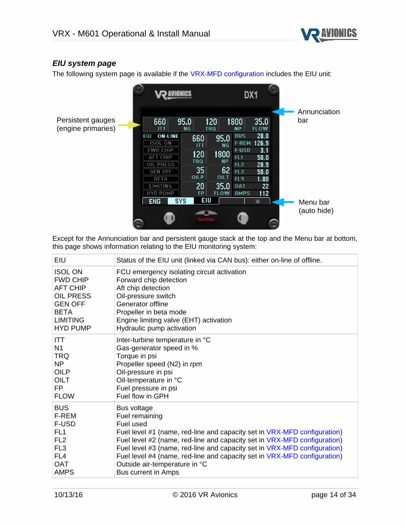
EIU system pageThe following system page is available if the VRX-MFD configuration includes the EIU unit:
Except for the Annunciation bar and persistent gauge stack at the top and the Menu bar at bottom, this page shows information relating to the EIU monitoring system:
EIU Status of the EIU unit (linked via CAN bus): either on-line of offline.
ISOL ONFWD CHIPAFT CHIPOIL PRESSGEN OFFBETALIMITINGHYD PUMP
FCU emergency isolating circuit activationForward chip detectionAft chip detectionOil-pressure switchGenerator offlinePropeller in beta modeEngine limiting valve (EHT) activationHydraulic pump activation
ITTN1TRQNPOILPOILTFPFLOW
Inter-turbine temperature in °CGas-generator speed in %Torque in psiPropeller speed (N2) in rpmOil-pressure in psiOil-temperature in °CFuel pressure in psiFuel flow in GPH
BUSF-REMF-USDFL1FL2FL3FL4OATAMPS
Bus voltageFuel remainingFuel usedFuel level #1 (name, red-line and capacity set in VRX-MFD configuration)Fuel level #2 (name, red-line and capacity set in VRX-MFD configuration)Fuel level #3 (name, red-line and capacity set in VRX-MFD configuration)Fuel level #4 (name, red-line and capacity set in VRX-MFD configuration)Outside air-temperature in °CBus current in Amps
10/13/16 © 2016 VR Avionics page 14 of 34
Menu bar(auto hide)
AnnunciationbarPersistent gauges
(engine primaries)

VRX - M601 Operational & Install Manual
FSM system pageThe following system page is available if the VRX-MFD configuration includes the FSM unit:
Except for the Annunciation bar and persistent gauge stack at the top and the Menu bar at bottom, this page shows information relating to the FSM system.
FSM Status of the FSM unit (linked via CAN bus): ON-LINE or OFFLINE
AUTO FUEL LEVELING
Status of Auto Fuel Leveling: OFF, ON-LEFT or ON-RIGHT
The fuel supply system graphic depends on the fuel layout configuration property selected. It can be adapted to depict other fuel tank arrangements.
The example FSM page shows a four fuel tank system – a center tank supplying the left tank, the left and right tanks supplying the header tank through two pumps and a selector, and the header able to vent back to the center tank through a valve (should air get into the header). Each tank shows a (gallons or liters) value.
The graphic further shows which pumps are active by drawing them yellow.
10/13/16 © 2016 VR Avionics page 15 of 34
Menu bar(auto hide)
AnnunciationbarPersistent gauges
(engine primaries)

VRX - M601 Operational & Install Manual
PDC system pageThe following system page is available if the VRX-MFD configuration includes the PDC unit:
Except for the Annunciation bar and persistent gauge stack at the top and the Menu bar at bottom, this page shows information relating to the PDC (propeller heating) system.
The propeller de-icing system graphic shows a propeller and spinner as from above. The heating elements (boots) are also depicted. Other readings show the following:
PROP HEAT Status of propeller heating – OFF, ON, FAIL or NA (not available).
MODE PDC unit's mode – standby, low heat, high heat, or offline.
TIMER Count-down timer to the next phase transition.
VOLT Voltage measured at the input of the PDC unit.
AMP-A Electrical current flowing through the phase A boot circuit (in Amps).
AMP-B Electrical current flowing through the phase B boot circuit (in Amps).
10/13/16 © 2016 VR Avionics page 16 of 34
Menu bar(auto hide)
AnnunciationbarPersistent gauges
(engine primaries)

VRX - M601 Operational & Install Manual
Fuel Level CalibrationsThe fuel levels measured by either the EIU or FSM can be calibrated / mapped via a VRD MFD, but only if the engine is not running. To begin the user must:
1. Navigate to either the EIU or FSM system page and select MENU.
2. From the menu select FL-CAL.
3. Prompted by CALIBRATE FUEL LEVEL 1 ? YES / NO select NO until you get to the one you wish to calibrate and then select YES. For the FSM fuel level 1=FL-L, 2=FL-C, 3=FL-R, and 4=FL-H.
4. You'll now be prompted to SET FUEL LEVEL SENSOR TYPE by entering in a value and then confirm it. Set it to the corresponding value below:
Fuel level sensor type EIU FSM
Not used / disabled 0 0
5 volt excitation frequency probe 1 1
5 volt excitation 0 – 5 volt analog voltage probe 2 2
Resistance probe (0 – 270 ohm) 3 -
12 volt excitation frequency probe 4 1
12 volt excitation 0 – 5 volt analog voltage probe 5 2
5. The fuel level mapping screen will appear showing 3 values. On the left is the LITER or GALLON value, on the right the SENSOR value / reading, and below in the middle the total points count value.
6. Starting with an empty tank fill it to the lowest amount you want displayed. This can be an empty tank if you wish. Using INC and DEC buttons (for increment and decrement) set the LITER of GALLON value to the amount you have poured in.
7. Press the ADD button to add this point. You'll see the points count increment to indicate that the point was added to the internal mapping table.
8. Repeat by pouring another amount of fuel into the tank, setting the LITER or GALLON value, and then adding that point to the internal mapping table. Note that there is 50 points available in the table so make sure you don't make the fuel increments too small and exhaust the 50 spots before you reach a full tank.
9. When the fuel tank reaches it's full value, enter and add this last point to the table, then select the DONE button.
10. You'll be prompted on whether you want to proceed and write the calibration table, YES or NO. Select YES to complete the process or no to cancel out back to the main menu.
Note: To have this all properly displayed on the VRX, you still need to set the relevant name, red-line and capacity properties in the VRX-MFD configuration of each VRD-MFD you use.
10/13/16 © 2016 VR Avionics page 17 of 34

VRX - M601 Operational & Install Manual
Flight Data RecordingThe flight data logging feature automatically stores engine data to a USB disk. Data is recorded to the USB disk every 0.3 to 10.0 seconds. A data file is created each time the system is powered on with a USB disk inserted. A 8 GB USB disk will conservatively store over 8,000 hours of engine data at the highest recording interval of 0.3 seconds. The data files stored on the USB disk have an extension of .CSV. This file format can be opened using a spread sheet application on a personal computer.
USB disk insertion and removal must be done while the MFD is not powered. At power-up a FL_XXXXP.CSV file is created where XXXX represents the flight number. The flight number increments each time the MFD is powered (even if no disk is inserted in the USB slot). This number will run from 0 to 9999 and roll over to zero again. The user can reset it via the Flight number configuration setting. The P in the example file name after the XXXX flight number signifies power-up. It will change to R to indicate that the engine was run (N1 > 10%) and thereafter change to F to signify that the Flight timer was started (N1 > Flight timer start N1).
The interval at which the MFD stores parameters is adjustable from 0.3 seconds to 10 seconds, which is adjustable via the Flight log interval configuration setting. Below is a sample flight log file opened in a spread sheet application.
In the ANNUNCIATION column of the spread sheet all activations are indicated with a “+” preceding the name of the annunciation light as listed in the Annunciation list. Similarly deactivation of any active annunciation light(s) are indicated by a “-” (minus) preceding the annunciation light name. For example “+EXCEED” in the annunciation column indicates the exceed light became active at that moment. Later in the flight “-EXCEED” will be written in the annunciation column at the moment the exceed light is deactivated.
10/13/16 © 2016 VR Avionics page 18 of 34
VRX - M601 Operational & Install Manual
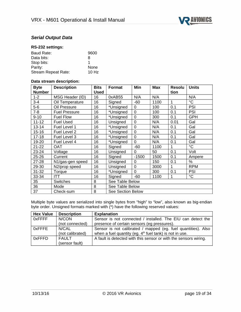
Serial Output Data
RS-232 settings:
Baud Rate: 9600Data bits: 8Stop bits: 1Parity: NoneStream Repeat Rate: 10 Hz
Data stream description:
Byte Number
Description Bits Used
Format Min Max Resolution
Units
1-2 MSG Header (ID) 16 0xAB55 N/A N/A N/A3-4 Oil Temperature 16 Signed -60 1100 1 °C5-6 Oil Pressure 16 *Unsigned 0 100 0.1 PSI7-8 Fuel Pressure 16 *Unsigned 0 100 0.1 PSI9-10 Fuel Flow 16 *Unsigned 0 300 0.1 GPH11-12 Fuel Used 16 Unsigned 0 N/A 0.01 Gal13-14 Fuel Level 1 16 *Unsigned 0 N/A 0.1 Gal15-16 Fuel Level 2 16 *Unsigned 0 N/A 0.1 Gal17-18 Fuel Level 3 16 *Unsigned 0 N/A 0.1 Gal19-20 Fuel Level 4 16 *Unsigned 0 N/A 0.1 Gal21-22 OAT 16 Signed -60 1100 1 °C23-24 Voltage 16 Unsigned 0 50 0.1 Volt25-26 Current 16 Signed -1500 1500 0.1 Ampere27-28 N1/gas-gen speed 16 Unsigned 0 150 0.1 %29-30 N2/prop speed 16 Unsigned 0 3000 1 RPM31-32 Torque 16 *Unsigned 0 300 0.1 PSI33-34 ITT 16 Signed -60 1100 1 °C35 Switches 8 See Table Below36 Mode 8 See Table Below37 Check-sum 8 See Section Below
Multiple byte values are serialized into single bytes from “high” to “low”, also known as big-endian byte order. Unsigned formats marked with (*) have the following reserved values:
Hex Value Description Explanation0xFFFF N/CON
(not connected)Sensor is not connected / installed. The EIU can detect the presence of certain sensors (eg pressures).
0xFFFE N/CAL(not calibrated)
Sensor is not calibrated / mapped (eg. fuel quantities). Also when a fuel quantity (eg. 4th fuel tank) is not in use.
0xFFFD FAULT(sensor fault)
A fault is detected with this sensor or with the sensors wiring.
10/13/16 © 2016 VR Avionics page 19 of 34
VRX - M601 Operational & Install Manual
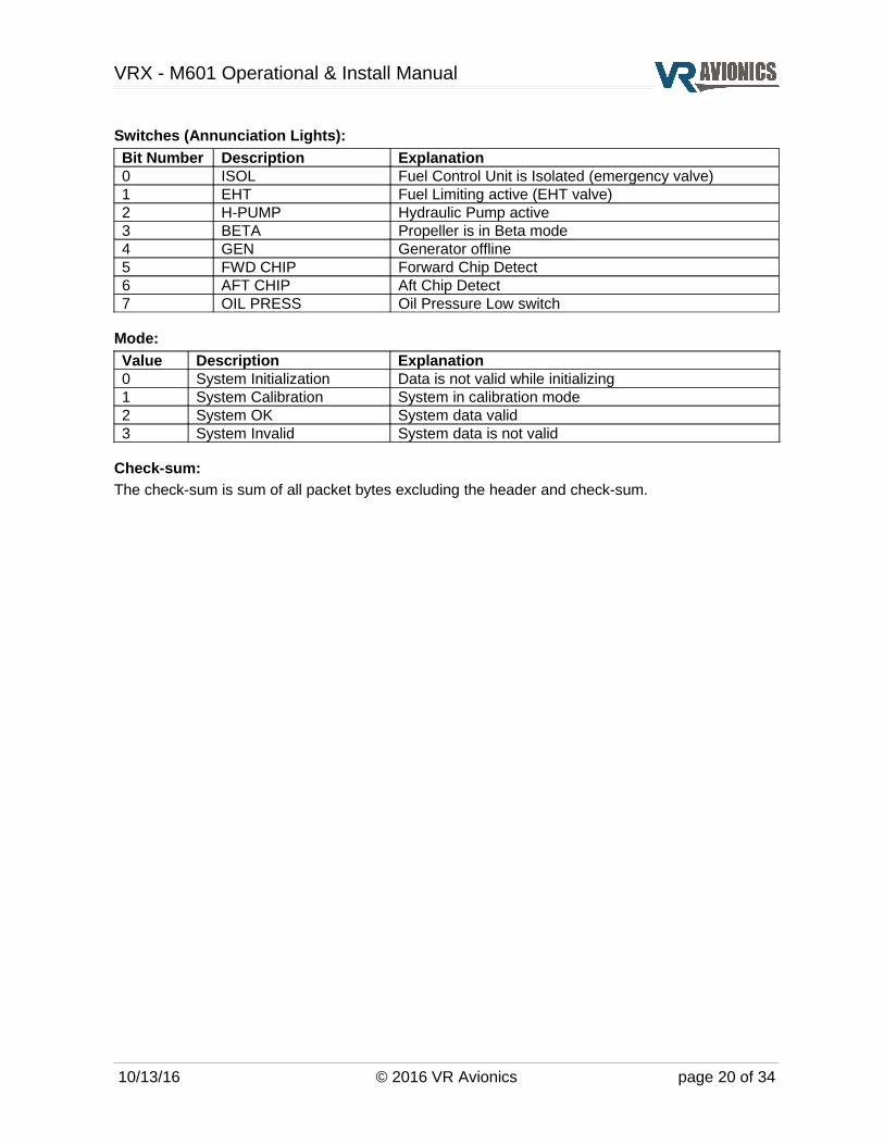
Switches (Annunciation Lights):
Bit Number Description Explanation0 ISOL Fuel Control Unit is Isolated (emergency valve)1 EHT Fuel Limiting active (EHT valve)2 H-PUMP Hydraulic Pump active3 BETA Propeller is in Beta mode4 GEN Generator offline5 FWD CHIP Forward Chip Detect 6 AFT CHIP Aft Chip Detect7 OIL PRESS Oil Pressure Low switch
Mode:
Value Description Explanation0 System Initialization Data is not valid while initializing1 System Calibration System in calibration mode2 System OK System data valid3 System Invalid System data is not valid
Check-sum:
The check-sum is sum of all packet bytes excluding the header and check-sum.
10/13/16 © 2016 VR Avionics page 20 of 34

VRX - M601 Operational & Install Manual
Installation
Mounting the VRD-10
Panel cutoutThe drawing below provides details on the cut-out hole to be made in a panel to accommodate the VRD-10 MFD. It is consistent with a standard 3.125” instrument hole. The display fits from the front and is secured using four 6-32 self-locking nuts such as the MS20365-632.
The unit will accommodate a socket driver or wrench to secure the nuts from the back of the panel as shown below.
10/13/16 © 2016 VR Avionics page 21 of 34
VRX - M601 Operational & Install Manual
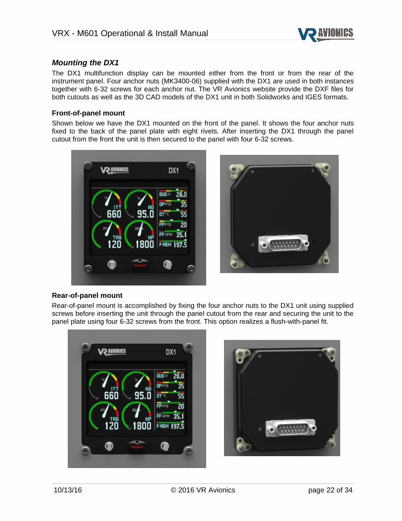
Mounting the DX1The DX1 multifunction display can be mounted either from the front or from the rear of the instrument panel. Four anchor nuts (MK3400-06) supplied with the DX1 are used in both instances together with 6-32 screws for each anchor nut. The VR Avionics website provide the DXF files for both cutouts as well as the 3D CAD models of the DX1 unit in both Solidworks and IGES formats.
Front-of-panel mountShown below we have the DX1 mounted on the front of the panel. It shows the four anchor nuts fixed to the back of the panel plate with eight rivets. After inserting the DX1 through the panel cutout from the front the unit is then secured to the panel with four 6-32 screws.
Rear-of-panel mountRear-of-panel mount is accomplished by fixing the four anchor nuts to the DX1 unit using supplied screws before inserting the unit through the panel cutout from the rear and securing the unit to the panel plate using four 6-32 screws from the front. This option realizes a flush-with-panel fit.
10/13/16 © 2016 VR Avionics page 22 of 34

VRX - M601 Operational & Install Manual
Electrical wiringThe following section describes the wiring requirements. Please follow these instructions closely as improper wiring can result in permanent damage to your unit.
Parts and toolsThe tools and equipment required are:
✔ Wire cutters
✔ Wire strippers
✔ Teflon insulated wire – 20 to 24 AWG
✔ Connector components (15-pin standard D-sub receptacle):
Description Qty Part NumbersCrimp Connector Shell 1 DAA15SA197FOCrimp Contacts 20-24 AWG 15 M24308/10-1 M39029/63-368
✔ Tools for working with M24308/10-1 crimp contacts (20-24 AWG):
Description Part NumbersCrimp tool M22520/2-01 AFM8 (DMC)Crimp tool positioner M22520/2-08 K13-1 (DMC)Extraction tool MS1969/1-02 DAK 145
Electrical wiring practicesNOTE: For all electrical connections, use correct splicing techniques, taking care to properly insulate any exposed wire. A short circuit between any of the wires may cause damage to the VRX-MFD and/or your airplane.
VR Avionics does not supply connectors or wire for wiring up your VRX MFD. We recommend that standard aircraft grade wiring and connectors be used. 20 gauge wire is sufficient for most lines to the unit. Make sure you protect the power lines with either a circuit breaker or fuse sized appropriate to the wire you select. We recommend you use wire meeting Mil Standard MIL-W-22759/16 (Tefzel insulation) which is available from various suppliers. Another option is to use Teflon insulated wire which is available in various colors.
We strongly recommend you use machined pin connectors to mate with the VRX MFD connector. Crimp connections have proven to be the most reliable in aircraft installations. D-Sub shells to hold the pins are available from various sources. Buying high quality connectors is a very wise investment in your aircraft. Make sure all connections are secure and all wires are routed and strain relieved to ensure the wires will not chafe against any other object in the aircraft.
Electrical installation of the VRX display unit is divided into the following sections:
Power and ground
Fuel flow circuit (optional)
Fuel pressure circuit (optional)
Emergency ISOL circuit (optional)
CAN bus connection
10/13/16 © 2016 VR Avionics page 23 of 34

VRX - M601 Operational & Install Manual
Power and groundThe diagram below shows how power and ground should be wired to the VRX MFD. A 5 amp circuit-breaker runs from the Main DC bus to the unit's pin 1 and another wire runs from pin 9 to ground. A lower rated circuit-breaker (or fuse) will also work since the unit draws little current (less than 0.2 amp). Wire gauges of 22 or 20 AWG is preferred.
Fuel flow circuitIf a VRX MFD have it's Fuel interface configuration property enabled, it will allow fuel flow sensing to drive the fuel computer. The diagram below shows how the fuel flow sensor should be connected.
Any pulse based fuel flow sensor, where the output frequency linearly represents the rate of flow, may be used. For the Walter M601 we usually recommend the FT-180 (black cube) from Electronics International (www.buy-ei.com).
10/13/16 © 2016 VR Avionics page 24 of 34

VRX - M601 Operational & Install Manual
Fuel pressure circuitWith the Fuel interface configuration property enabled on the VRX MFD unit it will measure and display fuel pressure. The diagram above shows how to wire the fuel pressure sensor. It shows how the sensor may be powered from the same circuit-breaker that the VRX display unit uses.
The fuel pressure sensor should be of the 4-20mA standard current output type and able to measure a pressure range of 0 - 50 psi such as the M5151-000005-050PG.
Emergency ISOL circuitWith the Fuel interface configuration property enabled the VRX MFD can sense ISOL activation. Connecting it is useful because if ISOL is active when the pilot issues a start sequence, the display will prompt the pilot to confirm the ISOL start operation. This is to prevent doing so unknowingly which may cause serious damage to the engine. The display will indicate an ISOL warning in the Annunciation bar when it is active.
To include this feature the circuit above must be wired-in. A small fuse (or ½ watt 10KΩ resistor) should be installed as indicated very close to the ISOL switch. This ensures no short in the line from the fuse to pin 2 on the MFD can hamper activation of the ISOL circuit.
Note: The ISOL signal (or for that matter fuel pressure, fuel flow, etc.) can alternatively be obtained via an EIU unit. Consult the EIU-M601 manual for more specifics and connection details.
10/13/16 © 2016 VR Avionics page 25 of 34

VRX - M601 Operational & Install Manual
CAN bus connectionVarious units share their information with the VRX multifunction display unit(s) via CAN bus. Shown below in blue is the backbone of the CAN bus consisting of 2-core twisted-pair shielded cable with 120 ohm termination resistors at each end. Here we show the largest possible system, but you only connect those units you have installed in yours.
Splicing of the CAN-H (high) and CAN-L (low) wires should preferably be done inside the connector back-shell of each unit.
10/13/16 © 2016 VR Avionics page 26 of 34

VRX - M601 Operational & Install Manual
Though not the preferred method, some VR Avionics units such as the VRD-10, DX1, EIU and FSM can realize the required termination resistor at one end by incorporating a simple loop-back wire at its connector. The following diagram show how a simple VRX MFD with TSLM system can be realized by connecting the CAN-T pin to the second CAN-L pin on the VRX MFD.
If the total length of the CAN bus cable that connects everything is short enough (under 2 meters) as the case may be in the above example the remaining 120 ohm termination resistor may be omitted.
10/13/16 © 2016 VR Avionics page 27 of 34

VRX - M601 Operational & Install Manual
ConfigurationThis chapter describes how the VRX MFD's settings can be adjusted to not only represent the installed system, but also suit the operator's preferences. Also covered here are the updating of firmware, not only of the VRX MFD, but of all the CAN bus connected VR Avionics units.
Adjusting the configurationTo access the system configuration the #4 (right most) button on the VRX MFD must be held in when power is applied to the unit. Power is typically applied through the aircraft's battery master switch. Afterward a screen similar to the one on the right will appear. It takes a second to load.
Here the VRX MFD and the units connected to it are listed, with each unit's serial number and firmware version next to it. The Menu bar at the bottom lists the actions available for each soft-key.
EXIT terminates configuration mode, UP and DOWN scrolls the cursor to highlight a particular unit, and ENTER lets you view a particular unit's configuration. To make adjustments a password must be entered.
If VRX-MFD is selected a screen similar to the one below will appear.
It lists the configuration properties and settings for the particular unit (the VRX-MFD with serial number 0100 in this case).
Once you have entered the password on the first configuration page you can adjust settings.
Select from the Menu bar BACK to return to the previous configuration list, UP and DOWN to scroll to a specific configuration property, and SET to adjust that property's setting.
Some settings are YES or NO and others require the entry of a value. Some configuration properties are for viewing only.
Configuration PasswordThe configuration password must be entered to adjust settings in the configuration and also to allow erasure of TSLM history on the TSLM unit. The password is initially set to 0100, but the user may change this at any time. After entering the password on the first configuration page shown above a CHANGE PASSWORD item will appear with the current password. The user may now change it. Please make sure to keep this password in a safe place to remember.
10/13/16 © 2016 VR Avionics page 28 of 34

VRX - M601 Operational & Install Manual
VRX-MFD configuration properties
Property Setting range Description / Notes
Primary display Yes / No Set to “Yes” if this is the primary display, which is the setting for a single VRX MFD installation. For dual MFD's one can be set “No” to make it a secondary display. See Dual display operation.
Alerting if primary Yes / No Enables Annunciation alerting (blinking until acknowledgment).
Alert delay in seconds 0 – 60 Delay in seconds before blinking begins and acknowledgment can be made.
Repeat acknowledged alerts Yes / No Set this to “No” to disable further alerting (blinking until acknowledgment) of those warnings that have been acknowledged by the pilot.
Fuel interface Yes / No Enables the fuel interface of this display.
Show FUEL page Yes / No Enables the FUEL system page to be shown.
Include TSLM Yes / No Makes the display expect a TSLM on the CAN bus.
Include FSM Yes / No Makes the display expect a FSM on the CAN bus.
Include PDC Yes / No Makes the display expect a PDC on the CAN bus.
Include EIU Yes / No Makes the display expect a EIU on the CAN bus.
Show oil-temp from TSLM Yes / No Makes the display use (prefer) the oil-temperature reading from the TSLM.
Fuel in liters Yes / No YES if fuel quantity should be in liter units instead of US gallons.
Fuel full value 0 – 9999 Set this to the total (maximum) amount of fuel on-board. One count equates to 0.1 gallons (or liters). This is the full fuel value used for fuel adjustment.
Fuel flow k-factor 0 – 99999 Set this to the k-factor that comes with your fuel flow sensor. It defines the sensor's unique pulses per US gallon value.
Fuel pressure calibration 650 – 700 This value is set at the factory. Adjust this only if the fuel pressure reading is confirmed wrong using another calibrated meter.
Fuel remaining warn level 0 – 9999 Fuel remaining where FUEL warning triggers. One count equates to 0.1 gallons (or liters).
Time remaining warn level 0 – 999 Time remaining where FUEL warning triggers. One count equates to 1 minute.
Flight timer start N1 0 – 999 N1 value where flight timer starts – take-off power application. One count equates to 0.1%
Flight timer stop N1 0 – 999 N1 value where the flight timer is stopped – engine shutdown. One count equates to 0.1%
Walter engine type 0 – 2 0 – M601D1 – M601E-112 – M601E-11A
10/13/16 © 2016 VR Avionics page 29 of 34
VRX - M601 Operational & Install Manual
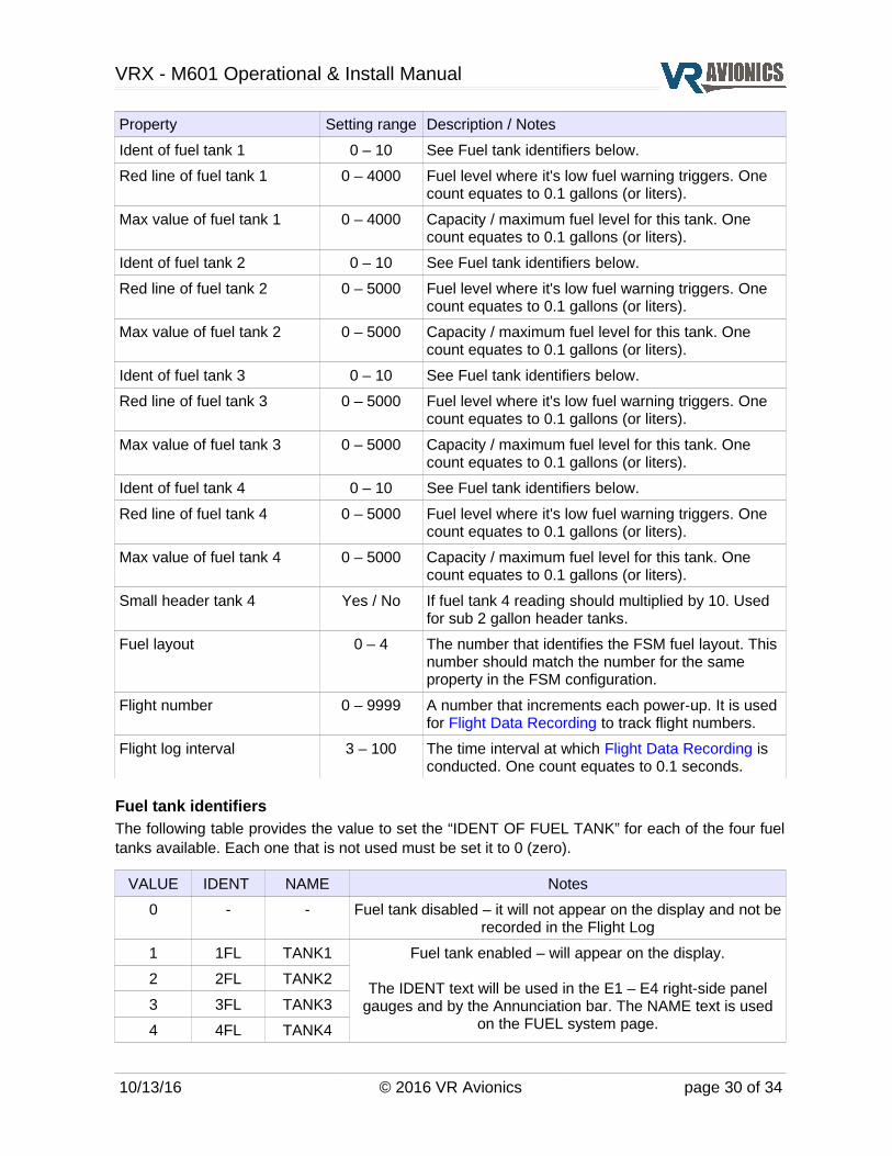
Property Setting range Description / Notes
Ident of fuel tank 1 0 – 10 See Fuel tank identifiers below.
Red line of fuel tank 1 0 – 4000 Fuel level where it's low fuel warning triggers. One count equates to 0.1 gallons (or liters).
Max value of fuel tank 1 0 – 4000 Capacity / maximum fuel level for this tank. One count equates to 0.1 gallons (or liters).
Ident of fuel tank 2 0 – 10 See Fuel tank identifiers below.
Red line of fuel tank 2 0 – 5000 Fuel level where it's low fuel warning triggers. One count equates to 0.1 gallons (or liters).
Max value of fuel tank 2 0 – 5000 Capacity / maximum fuel level for this tank. One count equates to 0.1 gallons (or liters).
Ident of fuel tank 3 0 – 10 See Fuel tank identifiers below.
Red line of fuel tank 3 0 – 5000 Fuel level where it's low fuel warning triggers. One count equates to 0.1 gallons (or liters).
Max value of fuel tank 3 0 – 5000 Capacity / maximum fuel level for this tank. One count equates to 0.1 gallons (or liters).
Ident of fuel tank 4 0 – 10 See Fuel tank identifiers below.
Red line of fuel tank 4 0 – 5000 Fuel level where it's low fuel warning triggers. One count equates to 0.1 gallons (or liters).
Max value of fuel tank 4 0 – 5000 Capacity / maximum fuel level for this tank. One count equates to 0.1 gallons (or liters).
Small header tank 4 Yes / No If fuel tank 4 reading should multiplied by 10. Used for sub 2 gallon header tanks.
Fuel layout 0 – 4 The number that identifies the FSM fuel layout. This number should match the number for the same property in the FSM configuration.
Flight number 0 – 9999 A number that increments each power-up. It is used for Flight Data Recording to track flight numbers.
Flight log interval 3 – 100 The time interval at which Flight Data Recording is conducted. One count equates to 0.1 seconds.
Fuel tank identifiersThe following table provides the value to set the “IDENT OF FUEL TANK” for each of the four fuel tanks available. Each one that is not used must be set it to 0 (zero).
VALUE IDENT NAME Notes
0 - - Fuel tank disabled – it will not appear on the display and not be recorded in the Flight Log
1 1FL TANK1 Fuel tank enabled – will appear on the display.
The IDENT text will be used in the E1 – E4 right-side panel gauges and by the Annunciation bar. The NAME text is used
on the FUEL system page.
2 2FL TANK2
3 3FL TANK3
4 4FL TANK4
10/13/16 © 2016 VR Avionics page 30 of 34

VRX - M601 Operational & Install Manual
VALUE IDENT NAME Notes
5 LFL LEFT
6 RFL RIGHT
7 AFL AUX
8 BFL BELLY
9 CFL CENTR
10 HFL HEADR
TSLM-M601 configuration properties
Property Setting range Description / Notes
Start cycles
See TSLM-M601 manual
Engine Hours
Lower ITT events
Upper ITT events
N1 events
N2 events
Torque events
*EHT resistance
ITT calibration
Voltage calibration
Torque span calibration
Torque offset calibration
Oil pressure span calibration
Oil pressure offset calibration
Oil temp. span calibration
Oil temp. offset calibration
Alternative int-valve enable
Double-click start override
Oil temp. measurement enable
Walter engine type 0 – 2
Start ITT control setting
* configuration properties marked with an asterisk are not user adjustable (for information only).
10/13/16 © 2016 VR Avionics page 31 of 34
VRX - M601 Operational & Install Manual
EIU-M601 configuration properties
Property Setting range Description / Notes
Temp. offset calibration
See EIU-M601 manual
Temp. span calibration
Voltage calibration
Shunt rating type
Shunt pos. calibration
Shunt neg. calibration
Torque span type
Torque span calibration
Oil pressure span type
Oil pressure calibration
Fuel pressure type
Fuel pressure calibration
N1 calibration
N2 calibration
Fuel flow k-factor
Fuel flow filter
Fuel tank designation
PDC configuration properties
Property Setting range Description / Notes
Operation
See PDC manual
Combine outputs
Blink phase states
Low cycle phase A on time
Low cycle phase B on time
Low cycle phases off time
High cycle phase A on time
High cycle phase B on time
High cycle phases off time
Operating current maximum
Operating current minimum
Current calibration
Voltage calibration
10/13/16 © 2016 VR Avionics page 32 of 34

VRX - M601 Operational & Install Manual
FSM configuration properties
Property Setting range Description / Notes
Fuel pressure warn level
See FSM Manual
Header quantity warn level
Fuel pump flow warn level
Fuel flow filter
Auto fuel level diff. wait enable
Use level readings for AFL
Auto fuel level diff.
Fuel pressure type
Fuel pressure calibration
Fuel flow k-factor left
Fuel flow k-factor center
Fuel flow k-factor right
Fuel full value left
Fuel full value center
Fuel full value right
Fuel layout
10/13/16 © 2016 VR Avionics page 33 of 34

VRX - M601 Operational & Install Manual
Updating firmwareTo update the system firmware a FAT32 formatted removable USB disk must be used like the one supplied with the MFD unit.
Confirming USB disk formatTo confirm a disk is formatted FAT32 you can insert it into a Windows PC, right click on the disk (listed under “Computer”) and select “Properties”. It should state FAT32 next to “File system”.
If you want to format a USB removable disk to FAT32 you can right click on the disk again and select “Format...”.
Copying files to USB diskOpen a new folder named “VRX” in the root of the disk (if not already there). Copy the firmware files to this folder (directory). Firmware files have an .VRB extension and the latest versions are available on our website.
Executing the updateEject the removable disk from your PC and insert it into the VRX MFD's USB slot. Press the #3 (second from right) button and hold it in while applying power (through the battery master switch). After turning on the power you may release the button. The VRX-MFD will begin updating it's own firmware and thereafter update any other VR unit connected to it according to the files in the VRX folder of the USB disk. Afterward a screen similar to the following will appear:
It lists every unit in the system starting with the current VRX-MFD. Each unit is listed with it's serial number and update status next to it. The following explains various update statuses:
DONE Unit's firmware have been successfully updated.
NO USB DISK No USB disk was detected in the VRX-MFD's slot.
NOT FAT32 The USB disk is not formatted with the FAT32 file system.
NO VRX FOLDER No VRX folder (directory) was found on the USB disk.
FILE MISSING The particular unit's firmware file was not found in the VRX folder and thus the unit was not updated.
FILE ERROR The firmware file for this unit was found to have an error and thus the update was not performed.
NO DETECT The particular unit could not be detected on the CAN bus and thus the update could not be done.
10/13/16 © 2016 VR Avionics page 34 of 34