TS 136 212 - V10.6.0 - LTE; Evolved Universal Terrestrial - ETSI
81
ETSI TS 136 212 V10.6.0 (2012-07) LTE; Evolved Universal Terrestrial Radio Access (E-UTRA); Multiplexing and channel coding (3GPP TS 36.212 version 10.6.0 Release 10) Technical Specification
Transcript of TS 136 212 - V10.6.0 - LTE; Evolved Universal Terrestrial - ETSI
ETSI TS 136 212 V1060 (2012-07)
LTE Evolved Universal Terrestrial Radio Access (E-UTRA)
Multiplexing and channel coding (3GPP TS 36212 version 1060 Release 10)
Technical Specification
ETSI
ETSI TS 136 212 V1060 (2012-07)13GPP TS 36212 version 1060 Release 10
Reference RTSTSGR-0136212va60
Keywords LTE
ETSI
650 Route des Lucioles F-06921 Sophia Antipolis Cedex - FRANCE
Tel +33 4 92 94 42 00 Fax +33 4 93 65 47 16
Siret Ndeg 348 623 562 00017 - NAF 742 C
Association agrave but non lucratif enregistreacutee agrave la Sous-Preacutefecture de Grasse (06) Ndeg 780388
Important notice
Individual copies of the present document can be downloaded from httpwwwetsiorg
The present document may be made available in more than one electronic version or in print In any case of existing or perceived difference in contents between such versions the reference version is the Portable Document Format (PDF)
In case of dispute the reference shall be the printing on ETSI printers of the PDF version kept on a specific network drive within ETSI Secretariat
Users of the present document should be aware that the document may be subject to revision or change of status Information on the current status of this and other ETSI documents is available at
httpportaletsiorgtbstatusstatusasp
If you find errors in the present document please send your comment to one of the following services httpportaletsiorgchaircorETSI_supportasp
Copyright Notification
No part may be reproduced except as authorized by written permission The copyright and the foregoing restriction extend to reproduction in all media
copy European Telecommunications Standards Institute 2012
All rights reserved
DECTTM PLUGTESTSTM UMTSTM and the ETSI logo are Trade Marks of ETSI registered for the benefit of its Members 3GPPTM and LTEtrade are Trade Marks of ETSI registered for the benefit of its Members and
of the 3GPP Organizational Partners GSMreg and the GSM logo are Trade Marks registered and owned by the GSM Association
ETSI
ETSI TS 136 212 V1060 (2012-07)23GPP TS 36212 version 1060 Release 10
Intellectual Property Rights IPRs essential or potentially essential to the present document may have been declared to ETSI The information pertaining to these essential IPRs if any is publicly available for ETSI members and non-members and can be found in ETSI SR 000 314 Intellectual Property Rights (IPRs) Essential or potentially Essential IPRs notified to ETSI in respect of ETSI standards which is available from the ETSI Secretariat Latest updates are available on the ETSI Web server (httpipretsiorg)
Pursuant to the ETSI IPR Policy no investigation including IPR searches has been carried out by ETSI No guarantee can be given as to the existence of other IPRs not referenced in ETSI SR 000 314 (or the updates on the ETSI Web server) which are or may be or may become essential to the present document
Foreword This Technical Specification (TS) has been produced by ETSI 3rd Generation Partnership Project (3GPP)
The present document may refer to technical specifications or reports using their 3GPP identities UMTS identities or GSM identities These should be interpreted as being references to the corresponding ETSI deliverables
The cross reference between GSM UMTS 3GPP and ETSI identities can be found under httpwebappetsiorgkeyqueryformasp
ETSI
ETSI TS 136 212 V1060 (2012-07)33GPP TS 36212 version 1060 Release 10
Contents
Intellectual Property Rights 2
Foreword 2
Foreword 5
1 Scope 6
2 References 6
3 Definitions symbols and abbreviations 6
31 Definitions 6
32 Symbols 6
33 Abbreviations 7
4 Mapping to physical channels 7
41 Uplink 7
42 Downlink 8
5 Channel coding multiplexing and interleaving 8
51 Generic procedures 8
511 CRC calculation 8
512 Code block segmentation and code block CRC attachment 9
513 Channel coding 11
5131 Tail biting convolutional coding 11
5132 Turbo coding 12
51321 Turbo encoder 12
51322 Trellis termination for turbo encoder 13
51323 Turbo code internal interleaver 13
514 Rate matching 15
5141 Rate matching for turbo coded transport channels 15
51411 Sub-block interleaver 15
51412 Bit collection selection and transmission 16
5142 Rate matching for convolutionally coded transport channels and control information 18
51421 Sub-block interleaver 19
51422 Bit collection selection and transmission 20
515 Code block concatenation 20
52 Uplink transport channels and control information 21
521 Random access channel 21
522 Uplink shared channel 21
5221 Transport block CRC attachment 22
5222 Code block segmentation and code block CRC attachment 22
5223 Channel coding of UL-SCH 23
5224 Rate matching 23
5225 Code block concatenation 23
5226 Channel coding of control information 23
52261 Channel quality information formats for wideband CQI reports 32
52262 Channel quality information formats for higher layer configured subband CQI reports 33
52263 Channel quality information formats for UE selected subband CQI reports 35
52264 Channel coding for CQIPMI information in PUSCH 36
52265 Channel coding for more than 11 bits of HARQ-ACK information 37
5227 Data and control multiplexing 38
5228 Channel interleaver 39
523 Uplink control information on PUCCH 41
5231 Channel coding for UCI HARQ-ACK 41
5232 Channel coding for UCI scheduling request 45
5233 Channel coding for UCI channel quality information 45
52331 Channel quality information formats for wideband reports 46
52332 Channel quality information formats for UE-selected sub-band reports 47
5234 Channel coding for UCI channel quality information and HARQ-ACK 50
ETSI
ETSI TS 136 212 V1060 (2012-07)43GPP TS 36212 version 1060 Release 10
524 Uplink control information on PUSCH without UL-SCH data 51
5241 Channel coding of control information 51
5242 Control information mapping 52
5243 Channel interleaver 52
53 Downlink transport channels and control information 52
531 Broadcast channel 52
5311 Transport block CRC attachment 53
5312 Channel coding 53
5313 Rate matching 54
532 Downlink shared channel Paging channel and Multicast channel 54
5321 Transport block CRC attachment 55
5322 Code block segmentation and code block CRC attachment 55
5323 Channel coding 55
5324 Rate matching 55
5325 Code block concatenation 55
533 Downlink control information 56
5331 DCI formats 56
53311 Format 0 56
53312 Format 1 57
53313 Format 1A 58
53313A Format 1B 60
53314 Format 1C 61
53314A Format 1D 62
53315 Format 2 63
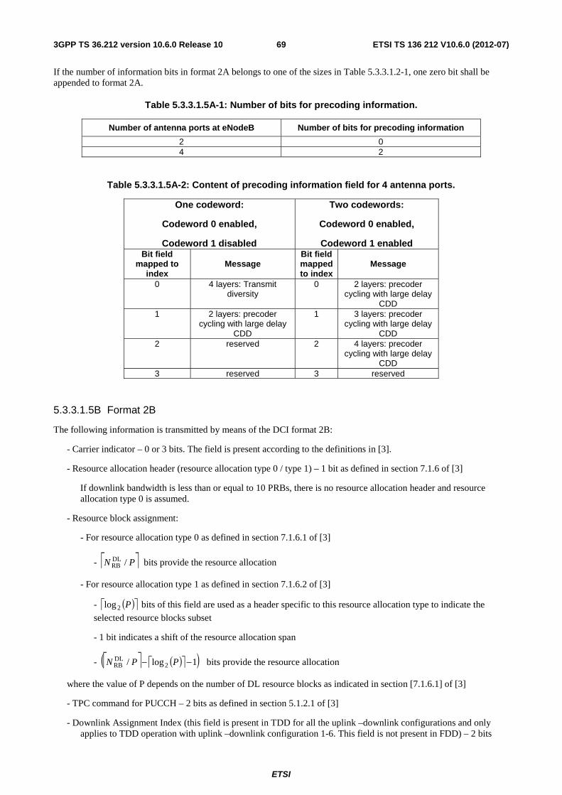
53315A Format 2A 67
53315B Format 2B 69
53315C Format 2C 70
53316 Format 3 71
53317 Format 3A 72
53318 Format 4 72
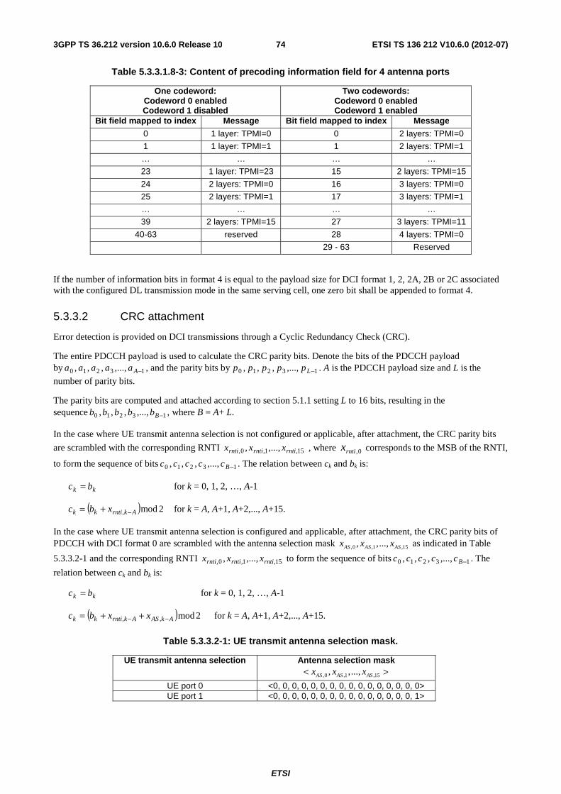
5332 CRC attachment 74
5333 Channel coding 75
5334 Rate matching 75
534 Control format indicator 75
5341 Channel coding 75
535 HARQ indicator (HI) 76
5351 Channel coding 76
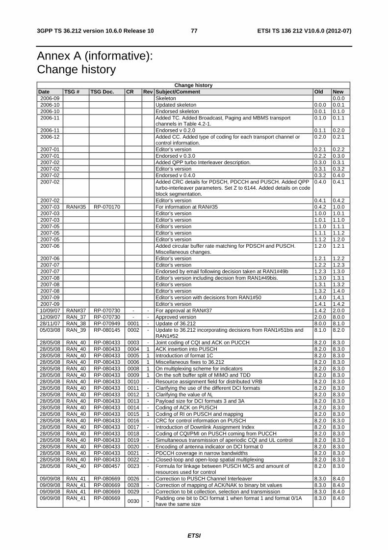
Annex A (informative) Change history 77
History 80
ETSI
ETSI TS 136 212 V1060 (2012-07)53GPP TS 36212 version 1060 Release 10
Foreword This Technical Specification has been produced by the 3rd Generation Partnership Project (3GPP)
The contents of the present document are subject to continuing work within the TSG and may change following formal TSG approval Should the TSG modify the contents of the present document it will be re-released by the TSG with an identifying change of release date and an increase in version number as follows
Version xyz
where
x the first digit
1 presented to TSG for information
2 presented to TSG for approval
3 or greater indicates TSG approved document under change control
Y the second digit is incremented for all changes of substance ie technical enhancements corrections updates etc
z the third digit is incremented when editorial only changes have been incorporated in the document
ETSI
ETSI TS 136 212 V1060 (2012-07)63GPP TS 36212 version 1060 Release 10
1 Scope The present document specifies the coding multiplexing and mapping to physical channels for E-UTRA
2 References The following documents contain provisions which through reference in this text constitute provisions of the present document
bull References are either specific (identified by date of publication edition number version number etc) or non-specific
bull For a specific reference subsequent revisions do not apply
bull For a non-specific reference the latest version applies In the case of a reference to a 3GPP document (including a GSM document) a non-specific reference implicitly refers to the latest version of that document in the same Release as the present document
[1] 3GPP TR 21905 Vocabulary for 3GPP Specifications
[2] 3GPP TS 36211 Evolved Universal Terrestrial Radio Access (E-UTRA) Physical channels and modulation
[3] 3GPP TS 36213 Evolved Universal Terrestrial Radio Access (E-UTRA) Physical layer procedures
[4] 3GPP TS 36306 Evolved Universal Terrestrial Radio Access (E-UTRA) User Equipment (UE) radio access capabilities
[5] 3GPP TS36321 ldquoEvolved Universal Terrestrial Radio Access (E-UTRA) Medium Access Control (MAC) protocol specificationrdquo
[6] 3GPP TS36331 ldquoEvolved Universal Terrestrial Radio Access (E-UTRA) Radio Resource Control (RRC) protocol specificationrdquo
3 Definitions symbols and abbreviations
31 Definitions For the purposes of the present document the terms and definitions given in [1] and the following apply A term defined in the present document takes precedence over the definition of the same term if any in [1]
Definition format
ltdefined termgt ltdefinitiongt
32 Symbols For the purposes of the present document the following symbols apply
DLRBN Downlink bandwidth configuration expressed in number of resource blocks [2] ULRBN Uplink bandwidth configuration expressed in number of resource blocks [2] RBscN Resource block size in the frequency domain expressed as a number of subcarriers
ETSI
ETSI TS 136 212 V1060 (2012-07)73GPP TS 36212 version 1060 Release 10
PUSCHsymbN Number of SC-FDMA symbols carrying PUSCH in a subframe
initial-PUSCHsymbN Number of SC-FDMA symbols carrying PUSCH in the initial PUSCH transmission subframe
ULsymbN Number of SC-FDMA symbols in an uplink slot
SRSN Number of SC-FDMA symbols used for SRS transmission in a subframe (0 or 1)
33 Abbreviations For the purposes of the present document the following abbreviations apply
BCH Broadcast channel CFI Control Format Indicator CP Cyclic Prefix DCI Downlink Control Information DL-SCH Downlink Shared channel FDD Frequency Division Duplexing HI HARQ indicator MCH Multicast channel PBCH Physical Broadcast channel PCFICH Physical Control Format Indicator channel PCH Paging channel PDCCH Physical Downlink Control channel PDSCH Physical Downlink Shared channel PHICH Physical HARQ indicator channel PMCH Physical Multicast channel PMI Precoding Matrix Indicator PRACH Physical Random Access channel PUCCH Physical Uplink Control channel PUSCH Physical Uplink Shared channel RACH Random Access channel RI Rank Indication SR Scheduling Request SRS Sounding Reference Signal TDD Time Division Duplexing TPMI Transmitted Precoding Matrix Indicator UCI Uplink Control Information UL-SCH Uplink Shared channel
4 Mapping to physical channels
41 Uplink Table 41-1 specifies the mapping of the uplink transport channels to their corresponding physical channels Table 41-2 specifies the mapping of the uplink control channel information to its corresponding physical channel
ETSI
ETSI TS 136 212 V1060 (2012-07)83GPP TS 36212 version 1060 Release 10
Table 41-1
TrCH Physical Channel UL-SCH PUSCH RACH PRACH
Table 41-2
Control information Physical Channel UCI PUCCH PUSCH
42 Downlink Table 42-1 specifies the mapping of the downlink transport channels to their corresponding physical channels Table 42-2 specifies the mapping of the downlink control channel information to its corresponding physical channel
Table 42-1
TrCH Physical Channel DL-SCH PDSCH BCH PBCH PCH PDSCH MCH PMCH
Table 42-2
Control information Physical Channel CFI PCFICH HI PHICH DCI PDCCH
5 Channel coding multiplexing and interleaving Data and control streams fromto MAC layer are encoded decoded to offer transport and control services over the radio transmission link Channel coding scheme is a combination of error detection error correcting rate matching interleaving and transport channel or control information mapping ontosplitting from physical channels
51 Generic procedures This section contains coding procedures which are used for more than one transport channel or control information type
511 CRC calculation
Denote the input bits to the CRC computation by 13210 minusAaaaaa and the parity bits by 13210 minusLppppp A
is the size of the input sequence and L is the number of parity bits The parity bits are generated by one of the following cyclic generator polynomials
- gCRC24A(D) = [D24 + D23 + D18 + D17 + D14 + D11 + D10 + D7 + D6 + D5 + D4 + D3 + D + 1] and
- gCRC24B(D) = [D24 + D23 + D6 + D5 + D + 1] for a CRC length L = 24 and
- gCRC16(D) = [D16 + D12 + D5 + 1] for a CRC length L = 16
- gCRC8(D) = [D8 + D7 + D4 + D3 + D + 1] for a CRC length of L = 8
ETSI
ETSI TS 136 212 V1060 (2012-07)93GPP TS 36212 version 1060 Release 10
The encoding is performed in a systematic form which means that in GF(2) the polynomial
231
2222
123
024
122
123
0 pDpDpDpDaDaDa AAA ++++++++ minus
++
yields a remainder equal to 0 when divided by the corresponding length-24 CRC generator polynomial gCRC24A(D) or gCRC24B(D) the polynomial
151
1414
115
016
114
115
0 pDpDpDpDaDaDa AAA ++++++++ minus
++
yields a remainder equal to 0 when divided by gCRC16(D) and the polynomial
71
66
17
08
16
17
0 pDpDpDpDaDaDa AAA ++++++++ minus
++
yields a remainder equal to 0 when divided by gCRC8(D)
The bits after CRC attachment are denoted by 13210 minusBbbbbb where B = A+ L The relation between ak and bk is
kk ab = for k = 0 1 2 hellip A-1
Akk pb minus= for k = A A+1 A+2 A+L-1
512 Code block segmentation and code block CRC attachment
The input bit sequence to the code block segmentation is denoted by 13210 minusBbbbbb where B gt 0 If B is larger
than the maximum code block size Z segmentation of the input bit sequence is performed and an additional CRC sequence of L = 24 bits is attached to each code block The maximum code block size is
- Z = 6144
If the number of filler bits F calculated below is not 0 filler bits are added to the beginning of the first block
Note that if B lt 40 filler bits are added to the beginning of the code block
The filler bits shall be set to ltNULLgt at the input to the encoder
Total number of code blocks C is determined by
if ZB le
L = 0
Number of code blocks 1=C
BB =prime
else
L = 24
Number of code blocks ( )⎡ ⎤LZBC minus=
LCBB sdot+=prime
end if
The bits output from code block segmentation for C ne 0 are denoted by ( )13210 minusrKrrrrr ccccc where r is the
code block number and Kr is the number of bits for the code block number r
Number of bits in each code block (applicable for C ne 0 only)
First segmentation size +K = minimum K in table 513-3 such that BKC primegesdot
ETSI
ETSI TS 136 212 V1060 (2012-07)103GPP TS 36212 version 1060 Release 10
if 1=C
the number of code blocks with length +K is +C =1 0=minusK 0=minusC
else if 1gtC
Second segmentation size minusK = maximum K in table 513-3 such that +lt KK
minus+ minus=Δ KKK
Number of segments of size minusK ⎥⎦
⎥⎢⎣
⎢
Δprimeminussdot
= +minus
K
BKCC
Number of segments of size +K minus+ minus= CCC
end if
Number of filler bits BKCKCF primeminussdot+sdot= minusminus++
for k = 0 to F-1 -- Insertion of filler bits
gt=lt NULLc k0
end for
k = F
s = 0
for r = 0 to C-1
if minuslt Cr
minus= KK r
else
+= KK r
end if
while LKk r minuslt
srk bc =
1+= kk
1+= ss
end while
if C gt1
The sequence ( )13210 minusminusLKrrrrr rccccc is used to calculate the CRC parity bits ( )1210 minusLrrrr pppp
according to section 511 with the generator polynomial gCRC24B(D) For CRC calculation it is assumed that filler bits if present have the value 0
while rKk lt
)( rKLkrrk pc minus+=
1+= kk end while
end if 0=k
ETSI
ETSI TS 136 212 V1060 (2012-07)113GPP TS 36212 version 1060 Release 10
end for
513 Channel coding
The bit sequence input for a given code block to channel coding is denoted by 13210 minusKccccc where K is the
number of bits to encode After encoding the bits are denoted by )(1
)(3
)(2
)(1
)(0 i
Diiii ddddd minus where D is the number of
encoded bits per output stream and i indexes the encoder output stream The relation between kc and )(ikd and between
K and D is dependent on the channel coding scheme
The following channel coding schemes can be applied to TrCHs
- tail biting convolutional coding
- turbo coding
Usage of coding scheme and coding rate for the different types of TrCH is shown in table 513-1 Usage of coding scheme and coding rate for the different control information types is shown in table 513-2
The values of D in connection with each coding scheme
- tail biting convolutional coding with rate 13 D = K
- turbo coding with rate 13 D = K + 4
The range for the output stream index i is 0 1 and 2 for both coding schemes
Table 513-1 Usage of channel coding scheme and coding rate for TrCHs
TrCH Coding scheme Coding rate UL-SCH
Turbo coding 13 DL-SCH
PCH MCH
BCH Tail biting
convolutional coding
13
Table 513-2 Usage of channel coding scheme and coding rate for control information
Control Information Coding scheme Coding rate
DCI Tail biting
convolutional coding
13
CFI Block code 116 HI Repetition code 13
UCI
Block code variable Tail biting
convolutional coding
13
5131 Tail biting convolutional coding
A tail biting convolutional code with constraint length 7 and coding rate 13 is defined
The configuration of the convolutional encoder is presented in figure 513-1
The initial value of the shift register of the encoder shall be set to the values corresponding to the last 6 information bits in the input stream so that the initial and final states of the shift register are the same Therefore denoting the shift register of the encoder by 5210 ssss then the initial value of the shift register shall be set to
ETSI
ETSI TS 136 212 V1060 (2012-07)123GPP TS 36212 version 1060 Release 10
( )iKi cs minusminus= 1
kc
)0(kd
)1(kd
)2(kd
Figure 513-1 Rate 13 tail biting convolutional encoder
The encoder output streams )0(kd )1(
kd and )2(kd correspond to the first second and third parity streams respectively as
shown in Figure 513-1
5132 Turbo coding
51321 Turbo encoder
The scheme of turbo encoder is a Parallel Concatenated Convolutional Code (PCCC) with two 8-state constituent encoders and one turbo code internal interleaver The coding rate of turbo encoder is 13 The structure of turbo encoder is illustrated in figure 513-2
The transfer function of the 8-state constituent code for the PCCC is
G(D) = ⎥⎦
⎤⎢⎣
⎡
)(
)(1
0
1
Dg
Dg
where
g0(D) = 1 + D2 + D3
g1(D) = 1 + D + D3
The initial value of the shift registers of the 8-state constituent encoders shall be all zeros when starting to encode the input bits
The output from the turbo encoder is
kk xd =)0(
kk zd =)1(
kk zd prime=)2(
for 1210 minus= Kk
If the code block to be encoded is the 0-th code block and the number of filler bits is greater than zero ie F gt 0 then
the encoder shall set ck = 0 k = 0hellip(F-1) at its input and shall set gt=lt NULLd k)0( k = 0hellip(F-1) and
gt=lt NULLd k)1( k = 0hellip(F-1) at its output
The bits input to the turbo encoder are denoted by 13210 minusKccccc and the bits output from the first and second 8-
state constituent encoders are denoted by 13210 minusKzzzzz and 13210 minusprimeprimeprimeprimeprime Kzzzzz respectively The bits output
from the turbo code internal interleaver are denoted by 110 minusprimeprimeprime Kccc and these bits are to be the input to the second 8-
state constituent encoder
ETSI
ETSI TS 136 212 V1060 (2012-07)133GPP TS 36212 version 1060 Release 10
kc
kcprime
kxprime
kx
kz
kzprime
Figure 513-2 Structure of rate 13 turbo encoder (dotted lines apply for trellis termination only)
51322 Trellis termination for turbo encoder
Trellis termination is performed by taking the tail bits from the shift register feedback after all information bits are encoded Tail bits are padded after the encoding of information bits
The first three tail bits shall be used to terminate the first constituent encoder (upper switch of figure 513-2 in lower position) while the second constituent encoder is disabled The last three tail bits shall be used to terminate the second constituent encoder (lower switch of figure 513-2 in lower position) while the first constituent encoder is disabled
The transmitted bits for trellis termination shall then be
KK xd =)0( 1)0(1 ++ = KK zd KK xd prime=+
)0(2 1
)0(3 ++ prime= KK zd
KK zd =)1( 2)1(
1 ++ = KK xd KK zd prime=+)1(
2 2)1(
3 ++ prime= KK xd
1)2(
+= KK xd 2)2(1 ++ = KK zd 1
)2(2 ++ prime= KK xd 2
)2(3 ++ prime= KK zd
51323 Turbo code internal interleaver
The bits input to the turbo code internal interleaver are denoted by 110 minusKccc where K is the number of input bits
The bits output from the turbo code internal interleaver are denoted by 110 minusprimeprimeprime Kccc
The relationship between the input and output bits is as follows
ETSI
ETSI TS 136 212 V1060 (2012-07)143GPP TS 36212 version 1060 Release 10
( )ii cc Π=prime i=0 1hellip (K-1)
where the relationship between the output index i and the input index )(iΠ satisfies the following quadratic form
( ) Kififi mod)( 221 sdot+sdot=Π
The parameters 1f and 2f depend on the block size K and are summarized in Table 513-3
Table 513-3 Turbo code internal interleaver parameters
i K 1f 2f i K 1f 2f i K 1f 2f i K 1f 2f
1 40 3 10 48 416 25 52 95 1120 67 140 142 3200 111 240 2 48 7 12 49 424 51 106 96 1152 35 72 143 3264 443 204 3 56 19 42 50 432 47 72 97 1184 19 74 144 3328 51 104 4 64 7 16 51 440 91 110 98 1216 39 76 145 3392 51 212 5 72 7 18 52 448 29 168 99 1248 19 78 146 3456 451 192 6 80 11 20 53 456 29 114 100 1280 199 240 147 3520 257 220 7 88 5 22 54 464 247 58 101 1312 21 82 148 3584 57 336 8 96 11 24 55 472 29 118 102 1344 211 252 149 3648 313 228 9 104 7 26 56 480 89 180 103 1376 21 86 150 3712 271 232
10 112 41 84 57 488 91 122 104 1408 43 88 151 3776 179 236 11 120 103 90 58 496 157 62 105 1440 149 60 152 3840 331 120 12 128 15 32 59 504 55 84 106 1472 45 92 153 3904 363 244 13 136 9 34 60 512 31 64 107 1504 49 846 154 3968 375 248 14 144 17 108 61 528 17 66 108 1536 71 48 155 4032 127 168 15 152 9 38 62 544 35 68 109 1568 13 28 156 4096 31 64 16 160 21 120 63 560 227 420 110 1600 17 80 157 4160 33 130 17 168 101 84 64 576 65 96 111 1632 25 102 158 4224 43 264 18 176 21 44 65 592 19 74 112 1664 183 104 159 4288 33 134 19 184 57 46 66 608 37 76 113 1696 55 954 160 4352 477 408 20 192 23 48 67 624 41 234 114 1728 127 96 161 4416 35 138 21 200 13 50 68 640 39 80 115 1760 27 110 162 4480 233 280 22 208 27 52 69 656 185 82 116 1792 29 112 163 4544 357 142 23 216 11 36 70 672 43 252 117 1824 29 114 164 4608 337 480 24 224 27 56 71 688 21 86 118 1856 57 116 165 4672 37 146 25 232 85 58 72 704 155 44 119 1888 45 354 166 4736 71 444 26 240 29 60 73 720 79 120 120 1920 31 120 167 4800 71 120 27 248 33 62 74 736 139 92 121 1952 59 610 168 4864 37 152 28 256 15 32 75 752 23 94 122 1984 185 124 169 4928 39 462 29 264 17 198 76 768 217 48 123 2016 113 420 170 4992 127 234 30 272 33 68 77 784 25 98 124 2048 31 64 171 5056 39 158 31 280 103 210 78 800 17 80 125 2112 17 66 172 5120 39 80 32 288 19 36 79 816 127 102 126 2176 171 136 173 5184 31 96 33 296 19 74 80 832 25 52 127 2240 209 420 174 5248 113 902 34 304 37 76 81 848 239 106 128 2304 253 216 175 5312 41 166 35 312 19 78 82 864 17 48 129 2368 367 444 176 5376 251 336 36 320 21 120 83 880 137 110 130 2432 265 456 177 5440 43 170 37 328 21 82 84 896 215 112 131 2496 181 468 178 5504 21 86 38 336 115 84 85 912 29 114 132 2560 39 80 179 5568 43 174 39 344 193 86 86 928 15 58 133 2624 27 164 180 5632 45 176 40 352 21 44 87 944 147 118 134 2688 127 504 181 5696 45 178 41 360 133 90 88 960 29 60 135 2752 143 172 182 5760 161 120 42 368 81 46 89 976 59 122 136 2816 43 88 183 5824 89 182 43 376 45 94 90 992 65 124 137 2880 29 300 184 5888 323 184 44 384 23 48 91 1008 55 84 138 2944 45 92 185 5952 47 186 45 392 243 98 92 1024 31 64 139 3008 157 188 186 6016 23 94 46 400 151 40 93 1056 17 66 140 3072 47 96 187 6080 47 190 47 408 155 102 94 1088 171 204 141 3136 13 28 188 6144 263 480
ETSI
ETSI TS 136 212 V1060 (2012-07)153GPP TS 36212 version 1060 Release 10
514 Rate matching
5141 Rate matching for turbo coded transport channels
The rate matching for turbo coded transport channels is defined per coded block and consists of interleaving the three
information bit streams )0(kd )1(
kd and )2(kd followed by the collection of bits and the generation of a circular buffer as
depicted in Figure 514-1 The output bits for each code block are transmitted as described in section 51412
)0(kd
)1(kd
)2(kd
ke
)0(kv
)1(kv
)2(kv
kw
Figure 514-1 Rate matching for turbo coded transport channels
The bit stream )0(kd is interleaved according to the sub-block interleaver defined in section 51411 with an output
sequence defined as )0(1
)0(2
)0(1
)0(0 minusΠKvvvv and where ΠK is defined in section 51411
The bit stream )1(kd is interleaved according to the sub-block interleaver defined in section 51411 with an output
sequence defined as )1(1
)1(2
)1(1
)1(0 minusΠKvvvv
The bit stream )2(kd is interleaved according to the sub-block interleaver defined in section 51411 with an output
sequence defined as )2(1
)2(2
)2(1
)2(0 minusΠKvvvv
The sequence of bits ke for transmission is generated according to section 51412
51411 Sub-block interleaver
The bits input to the block interleaver are denoted by )(1
)(2
)(1
)(0 i
Diii dddd minus where D is the number of bits The output
bit sequence from the block interleaver is derived as follows
(1) Assign 32=TCsubblockC to be the number of columns of the matrix The columns of the matrix are numbered 0 1
2hellip 1minusTCsubblockC from left to right
(2) Determine the number of rows of the matrix TCsubblockR by finding minimum integer TC
subblockR such that
( )TCsubblock
TCsubblock CRD timesle
The rows of rectangular matrix are numbered 0 1 2hellip 1minusTCsubblockR from top to bottom
ETSI
ETSI TS 136 212 V1060 (2012-07)163GPP TS 36212 version 1060 Release 10
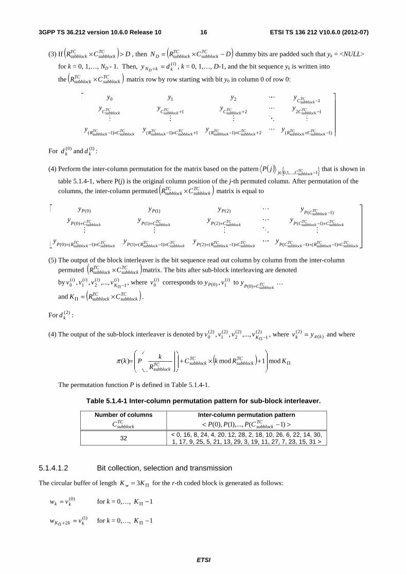
(3) If ( ) DCR TCsubblock
TCsubblock gttimes then ( )DCRN TC
subblockTCsubblockD minustimes= dummy bits are padded such that yk = ltNULLgt
for k = 0 1hellip ND - 1 Then )(ikkN dy
D=+ k = 0 1hellip D-1 and the bit sequence yk is written into
the ( )TCsubblock
TCsubblock CR times matrix row by row starting with bit y0 in column 0 of row 0
⎥⎥⎥⎥⎥
⎦
⎤
⎢⎢⎢⎢⎢
⎣
⎡
minustimes+timesminus+timesminustimesminus
minus++
minus
)1(2)1(1)1()1(
1221
1210
TCsubblock
TCsubblock
TCsubblock
TCsubblock
TCsubblock
TCsubblock
TCsubblock
TCsubblock
TCsubblock
TCsubblock
TCsubblock
TCsubblock
TCsubblock
CRCRCRCR
CCCC
C
yyyy
yyyy
yyyy
L
MOMMM
L
L
For )0(kd and )1(
kd
(4) Perform the inter-column permutation for the matrix based on the pattern ( ) 110 minusisin TCsubblockCj
jP that is shown in
table 514-1 where P(j) is the original column position of the j-th permuted column After permutation of the
columns the inter-column permuted ( )TCsubblock
TCsubblock CR times matrix is equal to
⎥⎥⎥⎥⎥
⎦
⎤
⎢⎢⎢⎢⎢
⎣
⎡
timesminus+minustimesminus+timesminus+timesminus+
+minus+++
minus
TCsubblock
TCsubblock
TCsubblock
TCsubblock
TCsubblock
TCsubblock
TCsubblock
TCsubblock
TCsubblock
TCsubblock
TCsubblock
TCsubblock
TCsubblock
TCsubblock
TCsubblock
CRCPCRPCRPCRP
CCPCPCPCP
CPPPP
yyyy
yyyy
yyyy
)1()1()1()2()1()1()1()0(
)1()2()1()0(
)1()2()1()0(
L
MOMMM
L
L
(5) The output of the block interleaver is the bit sequence read out column by column from the inter-column
permuted ( )TCsubblock
TCsubblock CR times matrix The bits after sub-block interleaving are denoted
by )(1
)(2
)(1
)(0 i
Kiii vvvv minusΠ
where )(0iv corresponds to )0(Py )(
1iv to TC
subblockCPy
+)0(hellip
and ( )TCsubblock
TCsubblock CRK times=Π
For )2(kd
(4) The output of the sub-block interleaver is denoted by )2(1
)2(2
)2(1
)2(0 minusΠKvvvv where )(
)2(kk yv π= and where
( ) Π⎟⎟
⎠
⎞
⎜⎜
⎝
⎛+times+
⎟⎟
⎠
⎞
⎜⎜
⎝
⎛
⎥⎥⎦
⎥
⎢⎢⎣
⎢= KRkC
R
kPk TC
subblockTCsubblockTC
subblock
mod1mod)(π
The permutation function P is defined in Table 514-1
Table 514-1 Inter-column permutation pattern for sub-block interleaver
Number of columns TCsubblockC
Inter-column permutation pattern
gtminuslt )1()1()0( TCsubblockCPPP
32 lt 0 16 8 24 4 20 12 28 2 18 10 26 6 22 14 30 1 17 9 25 5 21 13 29 3 19 11 27 7 23 15 31 gt
51412 Bit collection selection and transmission
The circular buffer of length Π= KK w 3 for the r-th coded block is generated as follows
)0(kk vw = for k = 0hellip 1minusΠK
)1(2 kkK vw =+Π
for k = 0hellip 1minusΠK
ETSI
ETSI TS 136 212 V1060 (2012-07)173GPP TS 36212 version 1060 Release 10
)2(12 kkK vw =++Π
for k = 0hellip 1minusΠK
Denote the soft buffer size for the transport block by NIR bits and the soft buffer size for the r-th code block by Ncb bits The size Ncb is obtained as follows where C is the number of code blocks computed in section 512
- ⎟⎟⎠
⎞⎜⎜⎝
⎛⎥⎦
⎥⎢⎣
⎢= wIR
cb KC
NN min for DL-SCH and PCH transport channels
- wcb KN = for UL-SCH and MCH transport channels
where NIR is equal to
( )⎥⎥⎦⎥
⎢⎢⎣
⎢
sdotsdot=
limitDL_HARQMIMO min MMKK
NN
C
softIR
where
If the UE signals ue-Category-v10xy and is configured with transmission mode 9 for the DL cell Nsoft is the total number of soft channel bits [4] according to the UE category indicated by ue-Category-v10xy [6] Otherwise Nsoft is the total number of soft channel bits [4] according to the UE category indicated by ue-Category [6]
If Nsoft = 35982720
KC= 5
elseif Nsoft = 3654144 and the UE is capable of supporting no more than a maximum of two spatial layers for the DL cell
KC = 2
else
KC = 1
End if
KMIMO is equal to 2 if the UE is configured to receive PDSCH transmissions based on transmission modes 3 4 8 or 9 as defined in section 71 of [3] and is equal to 1 otherwise
MDL_HARQ is the maximum number of DL HARQ processes as defined in section 7 of [3]
Mlimit is a constant equal to 8
Denoting by E the rate matching output sequence length for the r-th coded block and rvidx the redundancy version number for this transmission (rvidx = 0 1 2 or 3) the rate matching output bit sequence is ke k = 01 1minusE
Define by G the total number of bits available for the transmission of one transport block
Set ( )mL QNGG sdot=prime where Qm is equal to 2 for QPSK 4 for 16QAM and 6 for 64QAM and where
- For transmit diversity
- NL is equal to 2
- Otherwise
- NL is equal to the number of layers a transport block is mapped onto
Set CG modprime=γ where C is the number of code blocks computed in section 512
if 1minusminusle γCr
set ⎣ ⎦CGQNE mL primesdotsdot=
ETSI
ETSI TS 136 212 V1060 (2012-07)183GPP TS 36212 version 1060 Release 10
else
set ⎡ ⎤CGQNE mL primesdotsdot=
end if
Set⎟⎟
⎠
⎞
⎜⎜
⎝
⎛+sdot
⎥⎥⎥
⎤
⎢⎢⎢
⎡sdotsdot= 2
820 idxTC
subblock
cbTCsubblock rv
R
NRk where TC
subblockR is the number of rows defined in section 51411
Set k = 0 and j = 0
while k lt E
if gtnelt+ NULLwcbNjk mod)( 0
cbNjkk we mod)( 0 +=
k = k +1
end if
j = j +1
end while
5142 Rate matching for convolutionally coded transport channels and control information
The rate matching for convolutionally coded transport channels and control information consists of interleaving the
three bit streams )0(kd )1(
kd and )2(kd followed by the collection of bits and the generation of a circular buffer as
depicted in Figure 514-2 The output bits are transmitted as described in section 51422
)0(kd
)1(kd
)2(kd
ke
)0(kv
)1(kv
)2(kv
kw
Figure 514-2 Rate matching for convolutionally coded transport channels and control information
The bit stream )0(kd is interleaved according to the sub-block interleaver defined in section 51421 with an output
sequence defined as )0(1
)0(2
)0(1
)0(0 minusΠKvvvv and where ΠK is defined in section 51421
The bit stream )1(kd is interleaved according to the sub-block interleaver defined in section 51421 with an output
sequence defined as )1(1
)1(2
)1(1
)1(0 minusΠKvvvv
The bit stream )2(kd is interleaved according to the sub-block interleaver defined in section 51421 with an output
sequence defined as )2(1
)2(2
)2(1
)2(0 minusΠKvvvv
ETSI
ETSI TS 136 212 V1060 (2012-07)193GPP TS 36212 version 1060 Release 10
The sequence of bits ke for transmission is generated according to section 51422
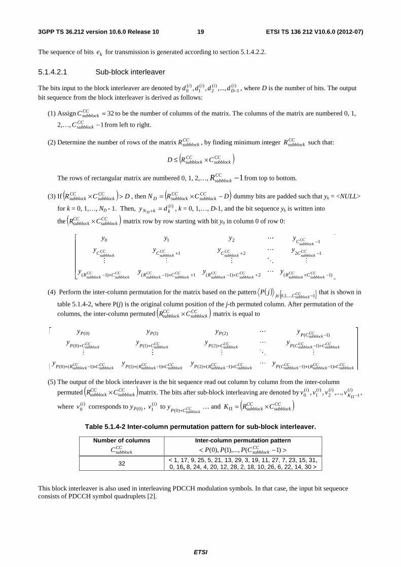
51421 Sub-block interleaver
The bits input to the block interleaver are denoted by )(1
)(2
)(1
)(0 i
Diii dddd minus where D is the number of bits The output
bit sequence from the block interleaver is derived as follows
(1) Assign 32=CCsubblockC to be the number of columns of the matrix The columns of the matrix are numbered 0 1
2hellip 1minusCCsubblockC from left to right
(2) Determine the number of rows of the matrix CCsubblockR by finding minimum integer CC
subblockR such that
( )CCsubblock
CCsubblock CRD timesle
The rows of rectangular matrix are numbered 0 1 2hellip 1minusCCsubblockR from top to bottom
(3) If ( ) DCR CCsubblock
CCsubblock gttimes then ( )DCRN CC
subblockCCsubblockD minustimes= dummy bits are padded such that yk = ltNULLgt
for k = 0 1hellip ND - 1 Then )(ikkN dy
D=+ k = 0 1hellip D-1 and the bit sequence yk is written into
the ( )CCsubblock
CCsubblock CR times matrix row by row starting with bit y0 in column 0 of row 0
⎥⎥⎥⎥⎥
⎦
⎤
⎢⎢⎢⎢⎢
⎣
⎡
minustimes+timesminus+timesminustimesminus
minus++
minus
)1(2)1(1)1()1(
1221
1210
CCsubblock
CCsubblock
CCsubblock
CCsubblock
CCsubblock
CCsubblock
CCsubblock
CCsubblock
CCsubblock
CCsubblock
CCsubblock
CCsubblock
CCsubblock
CRCRCRCR
CCCC
C
yyyy
yyyy
yyyy
L
MOMMM
L
L
(4) Perform the inter-column permutation for the matrix based on the pattern ( ) 110 minusisin CCsubblockCj
jP that is shown in
table 514-2 where P(j) is the original column position of the j-th permuted column After permutation of the
columns the inter-column permuted ( )CCsubblock
CCsubblock CR times matrix is equal to
⎥⎥⎥⎥⎥
⎦
⎤
⎢⎢⎢⎢⎢
⎣
⎡
timesminus+minustimesminus+timesminus+timesminus+
+minus+++
minus
CCsubblock
CCsubblock
CCsubblock
CCsubblock
CCsubblock
CCsubblock
CCsubblock
CCsubblock
CCsubblock
CCsubblock
CCsubblock
CCsubblock
CCsubblock
CCsubblock
CCsubblock
CRCPCRPCRPCRP
CCPCPCPCP
CPPPP
yyyy
yyyy
yyyy
)1()1()1()2()1()1()1()0(
)1()2()1()0(
)1()2()1()0(
L
MOMMM
L
L
(5) The output of the block interleaver is the bit sequence read out column by column from the inter-column
permuted ( )CCsubblock
CCsubblock CR times matrix The bits after sub-block interleaving are denoted by )(
1)(
2)(
1)(
0 iK
iii vvvv minusΠ
where )(0iv corresponds to )0(Py )(
1iv to CC
subblockCPy
+)0(hellip and ( )CC
subblockCCsubblock CRK times=Π
Table 514-2 Inter-column permutation pattern for sub-block interleaver
Number of columns CCsubblockC
Inter-column permutation pattern
gtminuslt )1()1()0( CCsubblockCPPP
32 lt 1 17 9 25 5 21 13 29 3 19 11 27 7 23 15 31 0 16 8 24 4 20 12 28 2 18 10 26 6 22 14 30 gt
This block interleaver is also used in interleaving PDCCH modulation symbols In that case the input bit sequence consists of PDCCH symbol quadruplets [2]
ETSI
ETSI TS 136 212 V1060 (2012-07)203GPP TS 36212 version 1060 Release 10
51422 Bit collection selection and transmission
The circular buffer of length Π= KK w 3 is generated as follows
)0(kk vw = for k = 0hellip 1minusΠK
)1(kkK vw =+Π
for k = 0hellip 1minusΠK
)2(2 kkK vw =+Π
for k = 0hellip 1minusΠK
Denoting by E the rate matching output sequence length the rate matching output bit sequence is ke k = 01 1minusE
Set k = 0 and j = 0
while k lt E
if gtnelt NULLwwKj mod
wKjk we mod=
k = k +1
end if
j = j +1
end while
515 Code block concatenation
The input bit sequence for the code block concatenation block are the sequences rke for 10 minus= Cr and
10 minus= rEk The output bit sequence from the code block concatenation block is the sequence kf for
10 minus= Gk
The code block concatenation consists of sequentially concatenating the rate matching outputs for the different code blocks Therefore
Set 0=k and 0=r
while Cr lt
Set 0=j
while rEj lt
rjk ef =
1+= kk
1+= jj
end while
1+= rr
end while
ETSI
ETSI TS 136 212 V1060 (2012-07)213GPP TS 36212 version 1060 Release 10
52 Uplink transport channels and control information
521 Random access channel
The sequence index for the random access channel is received from higher layers and is processed according to [2]
522 Uplink shared channel
Figure 522-1 shows the processing structure for the UL-SCH transport channel on one UL cell Data arrives to the coding unit in the form of a maximum of two transport blocks every transmission time interval (TTI) per UL cell The following coding steps can be identified for each transport block of an UL cell
minus Add CRC to the transport block
minus Code block segmentation and code block CRC attachment
minus Channel coding of data and control information
minus Rate matching
minus Code block concatenation
minus Multiplexing of data and control information
minus Channel interleaver
The coding steps for one UL-SCH transport block are shown in the figure below The same general processing applies for each UL-SCH transport block on each UL cell with restrictions as specified in [3]
ETSI
ETSI TS 136 212 V1060 (2012-07)223GPP TS 36212 version 1060 Release 10
Transport block
CRC attachment
Code block segmentation
Code block CRC attachment
Channel coding
Rate matching
Code block
concatenation
Data and Control multiplexing
Channel
coding
110 Aaaa
110 Bbbb
110
rKrrr
ccc
)(1
)(1
)(0
i
Dr
i
r
i
rr
ddd
110
rErrr
eee
110 Gfff
Channel Interleaver
10 hh
Channel
coding
Channel
coding
1L RIH N Qh + sdot minus
0 1 1
RI
RI RI RI
Qq q q
prime minus 0 1 1
ACK
ACK ACK ACK
Qq q q
prime minus
0 1 1[ ]RI
RI RI RI
Oo o o
minusL
0 1 1[ ]ACK
ACK ACK ACK
Oo o o
minusL0 1 1[ ]Oo o o minusL
0 1 1 L CQIN Qq q q sdot minusL
0 1 1
Hg g g
primeminus
Figure 522-1 Transport block processing for UL-SCH
5221 Transport block CRC attachment
Error detection is provided on each UL-SCH transport block through a Cyclic Redundancy Check (CRC)
The entire transport block is used to calculate the CRC parity bits Denote the bits in a transport block delivered to layer 1 by 13210 minusAaaaaa and the parity bits by 13210 minusLppppp A is the size of the transport block and L is the
number of parity bits The lowest order information bit a0 is mapped to the most significant bit of the transport block as defined in section 611 of [5]
The parity bits are computed and attached to the UL-SCH transport block according to section 511 setting L to 24 bits and using the generator polynomial gCRC24A(D)
5222 Code block segmentation and code block CRC attachment
The bits input to the code block segmentation are denoted by 13210 minusBbbbbb where B is the number of bits in the
transport block (including CRC)
ETSI
ETSI TS 136 212 V1060 (2012-07)233GPP TS 36212 version 1060 Release 10
Code block segmentation and code block CRC attachment are performed according to section 512
The bits after code block segmentation are denoted by ( )13210 minusrKrrrrr ccccc where r is the code block number
and Kr is the number of bits for code block number r
5223 Channel coding of UL-SCH
Code blocks are delivered to the channel coding block The bits in a code block are denoted by
( )13210 minusrKrrrrr ccccc where r is the code block number and Kr is the number of bits in code block number r
The total number of code blocks is denoted by C and each code block is individually turbo encoded according to section 5132
After encoding the bits are denoted by ( ))(
1)(
3)(
2)(
1)(
0 iDr
ir
ir
ir
ir r
ddddd minus with 2 and 10=i and where rD is the number of
bits on the i-th coded stream for code block number r ie 4+= rr KD
5224 Rate matching
Turbo coded blocks are delivered to the rate matching block They are denoted by ( ))(
1)(
3)(
2)(
1)(
0 iDr
ir
ir
ir
ir r
ddddd minus
with 2 and 10=i and where r is the code block number i is the coded stream index and rD is the number of bits in
each coded stream of code block number r The total number of code blocks is denoted by C and each coded block is individually rate matched according to section 5141
After rate matching the bits are denoted by ( )13210 minusrErrrrr eeeee where r is the coded block number and where
rE is the number of rate matched bits for code block number r
5225 Code block concatenation
The bits input to the code block concatenation block are denoted by ( )13210 minusrErrrrr eeeee for 10 minus= Cr and
where rE is the number of rate matched bits for the r-th code block
Code block concatenation is performed according to section 515
The bits after code block concatenation are denoted by 13210 minusGfffff where G is the total number of coded bits
for transmission of the given transport block over LN transmission layers excluding the bits used for control
transmission when control information is multiplexed with the UL-SCH transmission
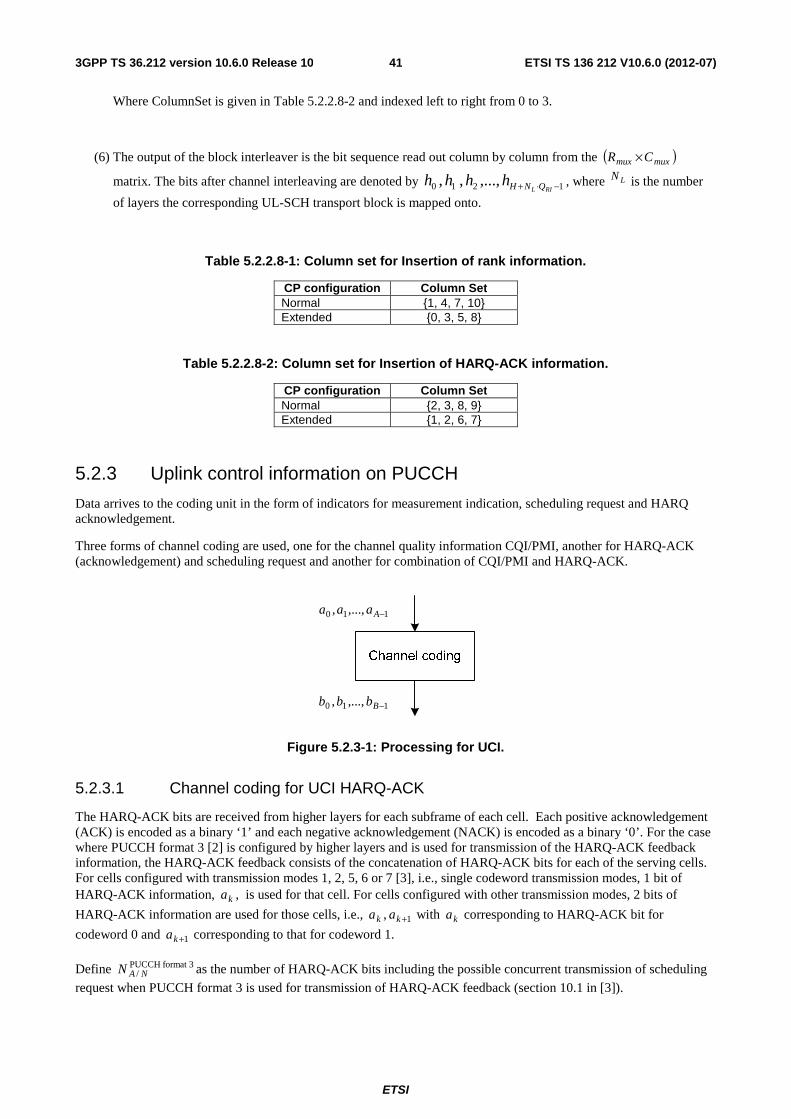
5226 Channel coding of control information
Control data arrives at the coding unit in the form of channel quality information (CQI andor PMI) HARQ-ACK and rank indication Different coding rates for the control information are achieved by allocating different number of coded symbols for its transmission When control data are transmitted in the PUSCH the channel coding for HARQ-ACK rank indication and channel quality information 1210 minusOoooo is done independently
For TDD the number of HARQ-ACK bits is determined as described in section 73 of [3]
When the UE transmits HARQ-ACK bits or rank indicator bits it shall determine the number of coded modulation symbols per layer Qprime for HARQ-ACK or rank indicator as follows
For the case when only one transport block is transmitted in the PUSCH conveying the HARQ-ACK bits or rank indicator bits
ETSI
ETSI TS 136 212 V1060 (2012-07)243GPP TS 36212 version 1060 Release 10
⎟⎟⎟⎟⎟
⎠
⎞
⎜⎜⎜⎜⎜
⎝
⎛
sdot
⎥⎥⎥⎥
⎥
⎤
⎢⎢⎢⎢
⎢
⎡sdotsdotsdot
=prime
summinus
=
minusminusPUSCHscC
rr
PUSCHoffset
initialPUSCHsymb
initialPUSCHsc M
K
NMOQ 4min
1
0
β
where O is the number of HARQ-ACK bits or rank indicator bits PUSCHscM is the scheduled bandwidth for PUSCH
transmission in the current sub-frame for the transport block expressed as a number of subcarriers in [2] and initial-PUSCH
symbN is the number of SC-FDMA symbols per subframe for initial PUSCH transmission for the same transport
block respectively given by ( )( )SRSULsymbsymb 12 NNN ialPUSCH-init minusminussdot= where SRSN is equal to 1 if UE transmits PUSCH
and SRS in the same subframe for initial transmission or if the PUSCH resource allocation for initial transmission even partially overlaps with the cell-specific SRS subframe and bandwidth configuration defined in section 553 of [2] or if the subframe for initial transmission is a UE-specific type-1 SRS subframe as defined in Section 82 of [3] Otherwise
SRSN is equal to 0 initialPUSCHscM minus C and rK are obtained from the initial PDCCH for the same transport block If
there is no initial PDCCH with DCI format 0 for the same transport block initialPUSCHscM minus C and rK shall be
determined from
minus the most recent semi-persistent scheduling assignment PDCCH when the initial PUSCH for the same transport block is semi-persistently scheduled or
minus the random access response grant for the same transport block when the PUSCH is initiated by the random access response grant
For the case when two transport blocks are transmitted in the PUSCH conveying the HARQ-ACK bits or rank indicator bits
( )[ ]min4minmax QMQQ PUSCHsctemp primesdotprime=prime with
⎥⎥⎥⎥⎥
⎥
⎤
⎢⎢⎢⎢⎢
⎢
⎡
sdotsdot+sdotsdot
sdotsdotsdotsdotsdotprime
sumsumminus
=
minusminusminus
=
minusminus
minusminusminusminus
=1
0
)1()1()2(1
0
)2()2()1(
)2()2()1()1(
)2()1( C
r
initialPUSCHsymb
initialPUSCHscr
C
r
initialPUSCHsymb
initialPUSCHscr
PUSCHoffset
initialPUSCHsymb
initialPUSCHsc
initialPUSCHsymb
initialPUSCHsc
temp
NMKNMK
NMNMOQ
β
where O is the number of HARQ-ACK bits or rank indicator bits OQ =primemin if 2leO ⎡ ⎤mQOQ prime=prime 2min if 113 lele O
with ( )21 min mmm QQQ =prime where 21 =xQ xm is the modulation order of transport block ldquoxrdquo and
⎡ ⎤ ⎡ ⎤mm QOQOQ prime+prime=prime 22 21min if 11gtO with ⎡ ⎤21 OO = and ⎡ ⎤22 OOO minus= 21)(sc =xM xialPUSCH-init are the
scheduled bandwidths for PUSCH transmission in the initial sub-frame for the first and second transport block
respectively expressed as a number of subcarriers in [2] and 21(x)symb =xN ialPUSCH-init are the number of SC-FDMA
symbols per subframe for initial PUSCH transmission for the first and second transport block given by
( )( ) 2112 )(SRS
ULsymb
)(symb =minusminussdot= xNNN xxialPUSCH-init where 21)( =xN x
SRS is equal to 1 if UE transmits PUSCH and
SRS in the same subframe for initial transmission of transport block ldquoxrdquo or if the PUSCH resource allocation for initial transmission of transport bock ldquoxrdquo even partially overlaps with the cell-specific SRS subframe and bandwidth configuration defined in section 553 of [2] or if the subframe for initial transmission of transport block ldquoxrdquo is a UE-
specific type-1 SRS subframe as defined in Section 82 of [3] Otherwise 21)( =xN xSRS is equal to 0
21)( =minus xM xinitialPUSCHsc 21)( =xC x and 21)( =xK x
r are obtained from the initial PDCCH for the
corresponding transport block
For HARQ-ACK QQQ mACK primesdot= and ACKHARQoffset
PUSCHoffset
minus= ββ where mQ is the modulation order of a given
transport block and ACKHARQoffset
minusβ shall be determined according to [3] depending on the number of transmission
codewords for the corresponding PUSCH
ETSI
ETSI TS 136 212 V1060 (2012-07)253GPP TS 36212 version 1060 Release 10
For rank indication QQQ mRI primesdot= and RIoffset
PUSCHoffset ββ = where mQ is the modulation order of a given transport
block and RIoffsetβ shall be determined according to [3] depending on the number of transmission codewords for the
corresponding PUSCH
For HARQ-ACK
minus Each positive acknowledgement (ACK) is encoded as a binary lsquo1rsquo and each negative acknowledgement (NACK) is encoded as a binary lsquo0rsquo
minus If HARQ-ACK feedback consists of 1-bit of information ie ][ 0ACKo it is first encoded according to Table
5226-1
minus If HARQ-ACK feedback consists of 2-bits of information ie ] [ 10ACKACK oo with 0
ACKo corresponding to
HARQ-ACK bit for codeword 0 and ACKo1 corresponding to that for codeword 1 or if HARQ-ACK feedback
consists of 2-bits of information as a result of the aggregation of HARQ-ACK bits corresponding to two DL cells with which the UE is configured by higher layers or if HARQ-ACK feedback consists of 2-bits of information corresponding to two DL subframes for TDD it is first encoded according to Table 5226-2
where 2mod) ( 102ACKACKACK ooo +=
Table 5226-1 Encoding of 1-bit HARQ-ACK
Qm Encoded HARQ-ACK 2 y] [ 0
ACKo
4 y x x] [ 0ACKo
6 ]y x x x x [ 0ACKo
Table 5226-2 Encoding of 2-bit HARQ-ACK
Qm Encoded HARQ-ACK 2 ] [ 210210
ACKACKACKACKACKACK oooooo
4 x x] x x x x [ 210210ACKACKACKACKACKACK oooooo
6 x x x x] x x x x x x x x [ 210210ACKACKACKACKACKACK oooooo
minus If HARQ-ACK feedback consists of 113 lele ACKO bits of information as a result of the aggregation of HARQ-
ACK bits corresponding to one or more DL cells with which the UE is configured by higher layers ie ACKO
ACKACKACKooo
110 minus
then a coded bit sequence ACKACKACK qqq 3110~~ ~ is obtained by using the bit sequence
ACKO
ACKACKACKooo
110 minus
as the input to the channel coding block described in section 52264 In turn the bit
sequence ACKQ
ACKACKACKACK
qqqq 1210 minus is obtained by the circular repetition of the bit sequence
ACKACKACK qqq 3110~~ ~ so that the total bit sequence length is equal to ACKQ
minus If HARQ-ACK feedback consists of 2011 lelt ACKO bits of information as a result of the aggregation of
HARQ-ACK bits corresponding to one or more DL cells with which the UE is configured by higher layers
ie ACKO
ACKACKACKooo
110 minus
then the coded bit sequence ACKQ
ACKACKACKACK
qqqq 1210 minus is obtained by using
the bit sequence ACKO
ACKACKACKooo
110 minus
as the input to the channel coding block described in section 52265
The ldquoxrdquo and ldquoyrdquo in Table 5226-1 and 5226-2 are placeholders for [2] to scramble the HARQ-ACK bits in a way that maximizes the Euclidean distance of the modulation symbols carrying HARQ-ACK information
ETSI
ETSI TS 136 212 V1060 (2012-07)263GPP TS 36212 version 1060 Release 10
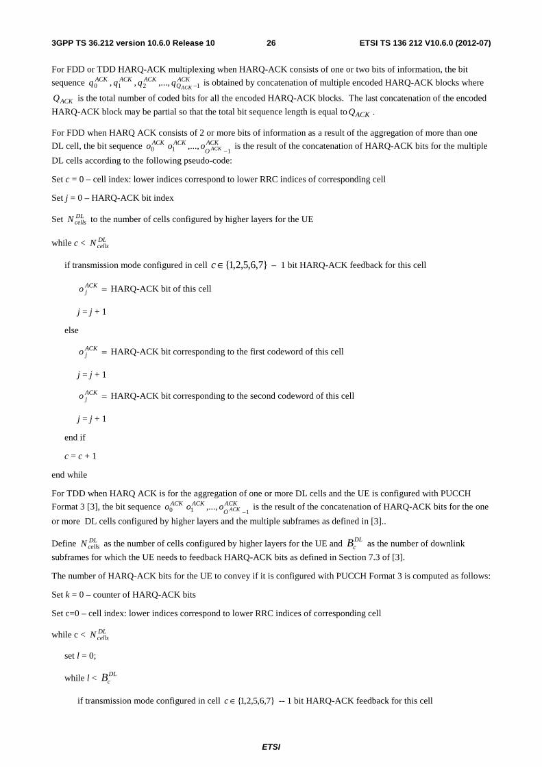
For FDD or TDD HARQ-ACK multiplexing when HARQ-ACK consists of one or two bits of information the bit
sequence ACKQ
ACKACKACKACK
qqqq 1210 minus is obtained by concatenation of multiple encoded HARQ-ACK blocks where
ACKQ is the total number of coded bits for all the encoded HARQ-ACK blocks The last concatenation of the encoded
HARQ-ACK block may be partial so that the total bit sequence length is equal to ACKQ
For FDD when HARQ ACK consists of 2 or more bits of information as a result of the aggregation of more than one
DL cell the bit sequence ACKO
ACKACKACKooo
110 minus
is the result of the concatenation of HARQ-ACK bits for the multiple
DL cells according to the following pseudo-code
Set c = 0 ndash cell index lower indices correspond to lower RRC indices of corresponding cell
Set j = 0 ndash HARQ-ACK bit index
Set DLcellsN to the number of cells configured by higher layers for the UE
while c lt DLcellsN
if transmission mode configured in cell 76521isinc ndash 1 bit HARQ-ACK feedback for this cell
=ACKjo HARQ-ACK bit of this cell
j = j + 1
else
=ACKjo HARQ-ACK bit corresponding to the first codeword of this cell
j = j + 1
=ACKjo HARQ-ACK bit corresponding to the second codeword of this cell
j = j + 1
end if
c = c + 1
end while
For TDD when HARQ ACK is for the aggregation of one or more DL cells and the UE is configured with PUCCH
Format 3 [3] the bit sequence ACKO
ACKACKACKooo
110 minus
is the result of the concatenation of HARQ-ACK bits for the one
or more DL cells configured by higher layers and the multiple subframes as defined in [3]
Define DLcellsN as the number of cells configured by higher layers for the UE and DL
cB as the number of downlink
subframes for which the UE needs to feedback HARQ-ACK bits as defined in Section 73 of [3]
The number of HARQ-ACK bits for the UE to convey if it is configured with PUCCH Format 3 is computed as follows
Set k = 0 ndash counter of HARQ-ACK bits
Set c=0 ndash cell index lower indices correspond to lower RRC indices of corresponding cell
while c lt DLcellsN
set l = 0
while l lt DLcB
if transmission mode configured in cell 76521isinc -- 1 bit HARQ-ACK feedback for this cell
ETSI
ETSI TS 136 212 V1060 (2012-07)273GPP TS 36212 version 1060 Release 10
k = k + 1
else
k = k + 2
end if
l = l+1
end while
c = c + 1
end while
If k le 20 the multiplexing of HARQ-ACK bits is performed according to the following pseudo-code
Set c = 0 ndash cell index lower indices correspond to lower RRC indices of corresponding cell
Set j = 0 ndash HARQ-ACK bit index
while c lt DLcellsN
set l = 0
while l lt DLcB
if transmission mode configured in cell 76521isinc -- 1 bit HARQ-ACK feedback for this cell
ACK
lcACKj oo
~ = HARQ-ACK bit of this cell as defined in Section 73 of [3]
j = j + 1
else
][]~~[ 1221ACK
lcACK
lcACKj
ACKj oooo ++ = HARQ-ACK bits of this cell as defined in Section 73 of [3]
j = j + 2
end if
l = l+1
end while
c = c + 1
end while
If k gt 20 spatial bundling is applied to all subframes in all cells and the multiplexing of HARQ-ACK bits is performed according to the following pseudo-code
Set c = 0 ndash cell index lower indices correspond to lower RRC indices of corresponding cell
Set j = 0 ndash HARQ-ACK bit index
while c lt DLcellsN
set l = 0
while l lt DLcB
if transmission mode configured in cell 76521isinc ndash 1 bit HARQ-ACK feedback for this cell
ETSI
ETSI TS 136 212 V1060 (2012-07)283GPP TS 36212 version 1060 Release 10
ACK
lcACKj oo
~ = HARQ-ACK bit of this cell as defined in Section 73 of [3]
j = j + 1
else
ACKlc
ACKj oo
~ = binary AND operation of the HARQ-ACK bits corresponding to the first and second
codewords of this cell as defined in Section 73 of [3]
j = j + 1
end if
l = l+1
end while
c = c + 1
end while
For 11leACKO the bit sequence ACK
OACKACK
ACKooo110
minus is obtained by setting ACK ACK
i io o=
For 2011 lelt ACKO the bit sequence ACK
OACKACK
ACKooo110
minus is obtained by setting 2
ACK ACKi io o= if i is even and
2 ( 1) 2ACK
ACK ACKiO i
o o⎡ ⎤+ minus⎢ ⎥
= if i is odd
For TDD when HARQ ACK is for the aggregation of two DL cells and the UE is configured with PUCCH format 1b
with channel selection the bit sequence ACKO
ACKACKACKooo
110 minus
is obtained as described in section 73 of [3]
For TDD HARQ-ACK bundling a bit sequence ACKQ
ACKACKACK
ACKqqqq 1210~~~~
minus is obtained by concatenation of
multiple encoded HARQ-ACK blocks where ACKQ is the total number of coded bits for all the encoded HARQ-ACK
blocks The last concatenation of the encoded HARQ-ACK block may be partial so that the total bit sequence length is
equal to ACKQ A scrambling sequence [ ]ACKACKACKACK wwww 3210 is then selected from Table 5226-A with index
( ) 4mod1minus= bundledNi where bundledN is determined as described in section 73 of [3] The bit sequence ACKQ
ACKACKACKACK
qqqq 1210 minus is then generated by setting 1=m if HARQ-ACK consists of 1-bit and 3=m if
HARQ-ACK consists of 2-bits and then scrambling ACKQ
ACKACKACK
ACKqqqq 1210~~~~
minus as follows
Set i k to 0
while ACKQi lt
if yq ACKi =~ place-holder repetition bit
⎣ ⎦( ) 2mod~
1ACK
mkACK
iACKi wqq += minus
mkk 4mod)1( +=
else
if xq ACKi =~ a place-holder bit
ACKi
ACKi qq ~=
else coded bit
ETSI
ETSI TS 136 212 V1060 (2012-07)293GPP TS 36212 version 1060 Release 10
⎣ ⎦( ) 2mod~
ACK
mkACK
iACKi wqq +=
mkk 4mod)1( +=
end if
1+= ii
end while
Table 5226-A Scrambling sequence selection for TDD HARQ-ACK bundling
i [ ]ACKACKACKACK wwww 3210
0 [1 1 1 1] 1 [1 0 1 0] 2 [1 1 0 0] 3 [1 0 0 1]
When HARQ-ACK information is to be multiplexed with UL-SCH at a given PUSCH the HARQ-ACK information is multiplexed in all layers of all transport blocks of that PUSCH For a given transport block the vector sequence output
of the channel coding for HARQ-ACK information is denoted by ACK
Q
ACKACK
ACKqqq
110
minusprime where ACK
iq
10 minusprime= ACKQi are column vectors of length ( )Lm NQ sdot and where mACKACK QQQ =prime is obtained as follows
Set i k to 0
while ACKQi lt
] [ˆ 1ACK
QiACKi
ACK
k mqqq minus+= -- temporary row vector
T
N
ACK
k
ACK
k
ACK
k
L
qqq ]ˆˆ[4484476
L= -- replicating the row vector ACK
kq NL times and transposing into a column vector
mQii +=
1+= kk
end while
where LN is the number of layers onto which the UL-SCH transport block is mapped
For rank indication (RI) (RI only joint report of RI and i1 and joint report of RI and PTI)
minus The corresponding bit widths for RI feedback for PDSCH transmissions are given by Tables 52261-2 52262-3 52263-3 52331-3 52331-3A 52332-4 and 52332-4A which are determined assuming the maximum number of layers according to the corresponding eNodeB antenna configuration and UE category
minus If RI feedback consists of 1-bit of information ie ][ 0RIo it is first encoded according to Table 5226-3 The
][ 0RIo to RI mapping is given by Table 5226-5
minus If RI feedback consists of 2-bits of information ie ] [ 10RIRI oo with RIo0 corresponding to MSB of 2-bit input
and RIo1 corresponding to LSB it is first encoded according to Table 5226-4 where
2mod) ( 102RIRIRI ooo += The ] [ 10
RIRI oo to RI mapping is given by Table 5226-6
ETSI
ETSI TS 136 212 V1060 (2012-07)303GPP TS 36212 version 1060 Release 10
Table 5226-3 Encoding of 1-bit RI
Qm Encoded RI 2 y] [ 0
RIo
4 y x x] [ 0RIo
6 ]y x x x x [ 0RIo
Table 5226-4 Encoding of 2-bit RI
Qm Encoded RI 2 ] [ 210210
RIRIRIRIRIRI oooooo
4 x x] x x x x [ 210210RIRIRIRIRIRI oooooo
6 x x x x] x x x x x x x x [ 210210RIRIRIRIRIRI oooooo
Table 5226-5 RIo0 to RI mapping
RIo0 RI
0 1 1 2
Table 5226-6 RIo0 RIo1 to RI mapping
RIo0 RIo1 RI
0 0 1 0 1 2 1 0 3 1 1 4
Table 5226-7 RIo0 RIo1 RIo2 to RI mapping
RIo0 RIo1 RIo2 RI
0 0 0 1 0 0 1 2 0 1 0 3 0 1 1 4 1 0 0 5 1 0 1 6 1 1 0 7 1 1 1 8
minus If RI feedback for a given DL cell consists of 3-bits of information ie ] [ 210RIRIRI ooo with RIo0 corresponding
to MSB of 3-bit input and RIo2 corresponding to LSB The ]o [ 210RIRIRI oo to RI mapping is given by Table
5226-7
minus If RI feedback consists of 113 lele RIO bits of information ie ] [110
RIO
RIRIRIooo
minus then a coded bit sequence
]~~ ~[ 3110RIRIRI qqq is obtained by using the bit sequence ] [
110RIO
RIRIRIooo
minus as the input to the channel coding
block described in section 52264
ETSI
ETSI TS 136 212 V1060 (2012-07)313GPP TS 36212 version 1060 Release 10
minus If RI feedback consists of 1511 lelt RIO bits of information as a result of the aggregation of RI bits
corresponding to multiple DL cells ie ] [110
RIO
RIRIRIooo
minus then the coded bit sequence
RIQ
RIRIRIRI
qqqq 1210 minus is obtained by using the bit sequence ] [110
RIO
RIRIRIooo
minus as the input to the channel
coding block described in section 52265
The ldquoxrdquo and ldquoyrdquo in Table 5226-3 and 5226-4 are placeholders for [2] to scramble the RI bits in a way that maximizes the Euclidean distance of the modulation symbols carrying rank information
For the case where RI feedback for more than one DL cell is to be reported the RI report for each DL cell is concatenated prior to coding in increasing order of cell index
For the case where RI feedback consists of one or two bits of information the bit sequence RIQ
RIRIRIRI
qqqq 1210 minus is
obtained by concatenation of multiple encoded RI blocks where RIQ is the total number of coded bits for all the
encoded RI blocks The last concatenation of the encoded RI block may be partial so that the total bit sequence length is equal to RIQ
For the case where RI feedback consists of 113 lele RIO bits of information the bit sequence RIQ
RIRIRIRI
qqqq 1210 minus is
obtained by the circular repetition of the bit sequence RIRIRI qqq 3110~~ ~ so that the total bit sequence length is equal
to RIQ
When rank information is to be multiplexed with UL-SCH at a given PUSCH the rank information is multiplexed in all layers of all transport blocks of that PUSCH For a given transport block the vector sequence output of the channel
coding for rank information is denoted by RIQ
RIRI
RIqqq
110
minusprime where RI
iq 10 minusprime= RIQi are column vectors of
length ( )Lm NQ sdot and where mRIRI QQQ =prime The vector sequence is obtained as follows
Set i j k to 0
while RIQi lt
] [ˆ 1RI
QiRIi
RI
k mqqq minus+= -- temporary row vector
T
N
RI
k
RI
k
RI
k
L
qqq ]ˆˆ[48476
L= -- replicating the row vector RI
kq NL times and transposing into a column vector
mQii +=
1+= kk
end while
where LN is the number of layers onto which the UL-SCH transport block is mapped
For channel quality control information (CQI andor PMI denoted as CQIPMI)
When the UE transmits channel quality control information bits it shall determine the number of modulation coded symbols per layer Qprime for channel quality information as
ETSI
ETSI TS 136 212 V1060 (2012-07)323GPP TS 36212 version 1060 Release 10
⎟⎟⎟⎟⎟
⎠
⎞
⎜⎜⎜⎜⎜
⎝
⎛
minussdot
⎥⎥⎥⎥
⎥
⎤
⎢⎢⎢⎢
⎢
⎡
sdotsdotsdot+=prime
summinus
=
minusminus
)(
)(
1
0
)(
)()(
)(
min )( xm
xRIPUSCH
symbPUSCHscC
r
xr
PUSCHoffset
xinitialPUSCHsymb
xinitialPUSCHsc
Q
QNM
K
NMLOQ x
β
where O is the number of CQIPMI bits L is the number of CRC bits given by ⎩⎨⎧ le
=otherwise8
110 OL
QQQ xmCQI primesdot= )( and CQI
offsetPUSCHoffset ββ = where CQI
offsetβ shall be determined according to [3] depending on the number
of transmission codewords for the corresponding PUSCH If RI is not transmitted then 0)( =xRIQ
The variable ldquoxrdquo in )(xrK represents the transport block index corresponding to the highest IMCS value indicated by the
initial UL grant In case the two transport blocks have the same IMCS value in the corresponding initial UL grant ldquox
=1rdquo which corresponds to the first transport block )( xinitialPUSCHscM minus )( xC and )(x
rK are obtained from the initial
PDCCH for the same transport block If there is no initial PDCCH with DCI format 0 for the same transport block )( xinitialPUSCH
scM minus )( xC and )(xrK shall be determined from
minus the most recent semi-persistent scheduling assignment PDCCH when the initial PUSCH for the same transport block is semi-persistently scheduled or
minus the random access response grant for the same transport block when the PUSCH is initiated by the random access response grant
)(xinitialPUSCHsymbN minus is the number of SC-FDMA symbols per subframe for initial PUSCH transmission for the same
transport block
For UL-SCH data information ( ))()(PUSCHsc
PUSCHsymb
)( xRICQI
xm
xL QQQMNNG minusminussdotsdotsdot= where )(x
LN is the number of layers the
corresponding UL-SCH transport block is mapped onto PUSCHscM is the scheduled bandwidth for PUSCH transmission
in the current sub-frame for the transport block and PUSCHsymbN is the number of SC-FDMA symbols in the current
PUSCH transmission sub-frame given by ( )( )SRSNNN minusminussdot= 12 ULsymb
PUSCHsymb where SRSN is equal to 1 if UE transmits
PUSCH and SRS in the same subframe for the current subframe or if the PUSCH resource allocation for the current subframe even partially overlaps with the cell-specific SRS subframe and bandwidth configuration defined in section 553 of [2] or if the current subframe is a UE-specific type-1 SRS subframe as defined in Section 82 of [3] Otherwise
SRSN is equal to 0
In case of CQIPMI report for more than one DL cell 1210 minusOoooo is the result of concatenating the CQIPMI
report for each DL cell in increasing order of cell index
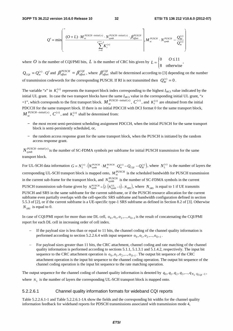
minus If the payload size is less than or equal to 11 bits the channel coding of the channel quality information is performed according to section 52264 with input sequence 1210 minusOoooo
minus For payload sizes greater than 11 bits the CRC attachment channel coding and rate matching of the channel quality information is performed according to sections 511 5131 and 5142 respectively The input bit sequence to the CRC attachment operation is 1210 minusOoooo The output bit sequence of the CRC
attachment operation is the input bit sequence to the channel coding operation The output bit sequence of the channel coding operation is the input bit sequence to the rate matching operation
The output sequence for the channel coding of channel quality information is denoted by 13210 minussdot CQIL QNqqqqq
where LN is the number of layers the corresponding UL-SCH transport block is mapped onto
52261 Channel quality information formats for wideband CQI reports
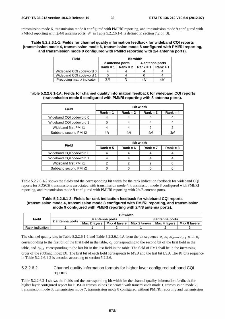
Table 52261-1 and Table 52261-1A show the fields and the corresponding bit widths for the channel quality information feedback for wideband reports for PDSCH transmissions associated with transmission mode 4
ETSI
ETSI TS 136 212 V1060 (2012-07)333GPP TS 36212 version 1060 Release 10
transmission mode 6 transmission mode 8 configured with PMIRI reporting and transmission mode 9 configured with PMIRI reporting with 248 antenna ports N in Table 52261-1 is defined in section 72 of [3]
Table 52261-1 Fields for channel quality information feedback for wideband CQI reports (transmission mode 4 transmission mode 6 transmission mode 8 configured with PMIRI reporting
and transmission mode 9 configured with PMIRI reporting with 24 antenna ports)
Field Bit width 2 antenna ports 4 antenna ports
Rank = 1 Rank = 2 Rank = 1 Rank gt 1 Wideband CQI codeword 0 4 4 4 4 Wideband CQI codeword 1 0 4 0 4 Precoding matrix indicator N2 N N4 N4
Table 52261-1A Fields for channel quality information feedback for wideband CQI reports (transmission mode 9 configured with PMIRI reporting with 8 antenna ports)
Field Bit width
Rank = 1 Rank = 2 Rank = 3 Rank = 4 Wideband CQI codeword 0 4 4 4 4
Wideband CQI codeword 1 0 4 4 4
Wideband first PMI i1 4 4 2 2
Subband second PMI i2 4N 4N 4N 3N
Field Bit width
Rank = 5 Rank = 6 Rank = 7 Rank = 8
Wideband CQI codeword 0 4 4 4 4
Wideband CQI codeword 1 4 4 4 4
Wideband first PMI i1 2 2 2 0
Subband second PMI i2 0 0 0 0
Table 52261-2 shows the fields and the corresponding bit width for the rank indication feedback for wideband CQI reports for PDSCH transmissions associated with transmission mode 4 transmission mode 8 configured with PMIRI reporting and transmission mode 9 configured with PMIRI reporting with 248 antenna ports
Table 52261-2 Fields for rank indication feedback for wideband CQI reports (transmission mode 4 transmission mode 8 configured with PMIRI reporting and transmission
mode 9 configured with PMIRI reporting with 248 antenna ports)
Field Bit width
2 antenna ports 4 antenna ports 8 antenna ports
Max 2 layers Max 4 layers Max 2 layers Max 4 layers Max 8 layers Rank indication 1 1 2 1 2 3
The channel quality bits in Table 52261-1 and Table 52261-1A form the bit sequence 1210 minusOoooo with 0o
corresponding to the first bit of the first field in the table 1o corresponding to the second bit of the first field in the
table and 1minusOo corresponding to the last bit in the last field in the table The field of PMI shall be in the increasing
order of the subband index [3] The first bit of each field corresponds to MSB and the last bit LSB The RI bits sequence in Table 52261-2 is encoded according to section 5226
52262 Channel quality information formats for higher layer configured subband CQI reports
Table 52262-1 shows the fields and the corresponding bit width for the channel quality information feedback for higher layer configured report for PDSCH transmissions associated with transmission mode 1 transmission mode 2 transmission mode 3 transmission mode 7 transmission mode 8 configured without PMIRI reporting and transmission
ETSI
ETSI TS 136 212 V1060 (2012-07)343GPP TS 36212 version 1060 Release 10
mode 9 configured without PMIRI reporting or configured with 1 antenna port N in Table 52262-1 is defined in section 72 of [3]
Table 52262-1 Fields for channel quality information feedback for higher layer configured subband CQI reports
(transmission mode 1 transmission mode 2 transmission mode 3 transmission mode 7 transmission mode 8 configured without PMIRI reporting and transmission mode 9 configured
without PMIRI reporting or configured with 1 antenna port)
Field Bit width
Wide-band CQI codeword 4 Subband differential CQI N2
Table 52262-2 and Table 52262-2A show the fields and the corresponding bit widths for the channel quality information feedback for higher layer configured report for PDSCH transmissions associated with transmission mode 4 transmission mode 5 transmission mode 6 transmission mode 8 configured with PMIRI reporting and transmission mode 9 configured with PMIRI reporting with 248 antenna ports N in Table 52262-2 is defined in section 72 of [3]
Table 52262-2 Fields for channel quality information feedback for higher layer configured subband CQI reports
(transmission mode 4 transmission mode 5 transmission mode 6 transmission mode 8 configured with PMIRI reporting and transmission mode 9 configured with PMIRI reporting with 24 antenna
ports)
Field Bit width 2 antenna ports 4 antenna ports
Rank = 1 Rank = 2 Rank = 1 Rank gt 1 Wide-band CQI codeword 0 4 4 4 4
Subband differential CQI codeword 0 N2 N2 N2 N2 Wide-band CQI codeword 1 0 4 0 4
Subband differential CQI codeword 1 0 N2 0 N2 Precoding matrix indicator 2 1 4 4
Table 52262-2A Fields for channel quality information feedback for higher layer configured subband CQI reports (transmission mode 9 configured with PMIRI reporting with 8 antenna ports)
Field Bitwidth
Rank = 1 Rank = 2 Rank = 3 Rank = 4 Wideband CQI codeword 0 4 4 4 4
Subband differential CQI codeword 0 N2 N2 N2 N2
Wideband CQI codeword 1 0 4 4 4 Subband differential CQI codeword 1 0 N2 N2 N2
Wideband first PMI i1 4 4 2 2 Subband second PMI i2 4 4 4 3
Field Bitwidth
Rank = 5 Rank = 6 Rank = 7 Rank = 8 Wideband CQI codeword 0 4 4 4 4
Subband differential CQI codeword 0 N2 N2 N2 N2
Wideband CQI codeword 1 4 4 4 4 Subband differential CQI codeword 1 N2 N2 N2 N2
Wideband first PMI i1 2 2 2 0 Subband second PMI i2 0 0 0 0
Table 52262-3 shows the fields and the corresponding bit width for the rank indication feedback for higher layer configured subband CQI reports for PDSCH transmissions associated with transmission mode 3 transmission mode 4
ETSI
ETSI TS 136 212 V1060 (2012-07)353GPP TS 36212 version 1060 Release 10
transmission mode 8 configured with PMIRI reporting and transmission mode 9 configured with PMIRI reporting with 248 antenna ports
Table 52262-3 Fields for rank indication feedback for higher layer configured subband CQI reports (transmission mode 3 transmission mode 4 transmission mode 8 configured with PMIRI reporting
and transmission mode 9 configured with PMIRI reporting with 248 antenna ports)
Field Bit width
2 antenna ports 4 antenna ports 8 antenna ports
Max 2 layers Max 4 layers Max 2 layers Max 4 layers Max 8 layers Rank indication 1 1 2 1 2 3
The channel quality bits in Table 52262-1 Table 52262-2 and Table 52262-2A form the bit sequence
1210 minusOoooo with 0o corresponding to the first bit of the first field in each of the tables 1o corresponding to the
second bit of the first field in each of the tables and 1minusOo corresponding to the last bit in the last field in each of the
tables The field of the PMI and subband differential CQI shall be in the increasing order of the subband index [3] The first bit of each field corresponds to MSB and the last bit LSB The RI bits sequence in Table 52262-3 is encoded according to section 5226
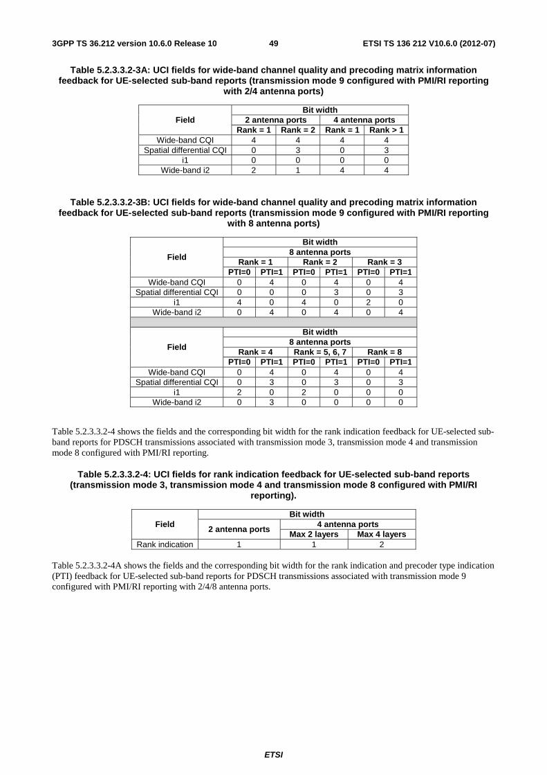
52263 Channel quality information formats for UE selected subband CQI reports
Table 52263-1 shows the fields and the corresponding bit widths for the channel quality information feedback for UE selected subband CQI for PDSCH transmissions associated with transmission mode 1 transmission mode 2 transmission mode 3 transmission mode 7 transmission mode 8 configured without PMIRI reporting and transmission mode 9 configured without PMIRI reporting or configured with 1 antenna port L in Table 52263-1 is defined in section 72 of [3]
Table 52263-1 Fields for channel quality information feedback for UE selected subband CQI reports
(transmission mode 1 transmission mode 2 transmission mode 3 transmission mode 7 transmission mode 8 configured without PMIRI reporting and transmission mode 9 configured
without PMIRI reporting or configured with 1 antenna port)
Field Bit width
Wide-band CQI codeword 4 Subband differential CQI 2
Position of the M selected subbands L Table 52263-2 and Table 52263-2A show the fields and the corresponding bit widths for the channel quality information feedback for UE selected subband CQI for PDSCH transmissions associated with transmission mode 4 transmission mode 6 transmission mode 8 configured with PMIRI reporting and transmission mode 9 configured with PMIRI reporting with 248 antenna ports L in Table 52263-2 is defined in section 72 of [3]
Table 52263-2 Fields for channel quality information feedback for UE selected subband CQI reports
(transmission mode 4 transmission mode 6 transmission mode 8 configured with PMIRI reporting and transmission mode 9 configured with PMIRI reporting with 24 antenna ports)
Field Bit width 2 antenna ports 4 antenna ports
Rank = 1 Rank = 2 Rank = 1 Rank gt 1 Wide-band CQI codeword 0 4 4 4 4
Subband differential CQI codeword 0 2 2 2 2 Wide-band CQI codeword 1 0 4 0 4
Subband differential CQI codeword 1 0 2 0 2 Position of the M selected subbands L L L L
Precoding matrix indicator 4 2 8 8
ETSI
ETSI TS 136 212 V1060 (2012-07)363GPP TS 36212 version 1060 Release 10
Table 52263-2A Fields for channel quality information feedback for UE selected subband CQI reports (transmission mode 9 configured with PMIRI reporting with 8 antenna ports)
Field Bit width
Rank = 1
Rank = 2
Rank = 3
Rank = 4
Rank = 5
Rank = 6
Rank = 7
Rank = 8
Wide-band CQI codeword 0 4 4 4 4 4 4 4 4 Subband differential CQI
codeword 0 2 2 2 2 2 2 2 2
Wide-band CQI codeword 1 0 4 4 4 4 4 4 4 Subband differential CQI
codeword 1 0 2 2 2 2 2 2 2
Position of the M selected subbands
L L L L L L L L
Wideband first PMI i1 4 4 2 2 2 2 2 0 Wideband second PMI i2 4 4 4 3 0 0 0 0 Subband second PMI i2 4 4 4 3 0 0 0 0
Table 52263-3 shows the fields and the corresponding bit widths for the rank indication feedback for UE selected subband CQI reports for PDSCH transmissions associated with transmission mode 3 transmission mode 4 transmission mode 8 configured with PMIRI reporting and transmission mode 9 configured with PMIRI reporting with 248 antenna ports
Table 52263-3 Fields for rank indication feedback for UE selected subband CQI reports (transmission mode 3 transmission mode 4 transmission mode 8 configured with PMIRI reporting
and transmission mode 9 configured with PMIRI reporting with 248 antenna ports)
Field Bit width
2 antenna ports 4 antenna ports 8 antenna ports
Max 2 layers Max 4 layers Max 2 layers Max 4 layers Max 8 layers Rank indication 1 1 2 1 2 3
The channel quality bits in Table 52263-1 Table 52263-2 and Table 52263-2A form the bit sequence
1210 minusOoooo with 0o corresponding to the first bit of the first field in each of the tables 1o corresponding to the
second bit of the first field in each of the tables and 1minusOo corresponding to the last bit in the last field in each of the
tables The field of PMI shall start with the wideband PMI followed by the PMI for the M selected subbands The first bit of each field corresponds to MSB and the last bit LSB The RI bits sequence in Table 52263-3 is encoded according to section 5226
52264 Channel coding for CQIPMI information in PUSCH
The channel quality bits input to the channel coding block are denoted by 13210 minusOooooo where O is the
number of bits The number of channel quality bits depends on the transmission format When PUCCH-based reporting format is used the number of CQIPMI bits is defined in section 52331 for wideband reports and in section 52332 for UE selected subbands reports When PUSCH-based reporting format is used the number of CQIPMI bits is defined in section 52261 for wideband reports in section 52262 for higher layer configured subbands reports and in section 52263 for UE selected subbands reports
The channel quality information is first coded using a (32 O) block code The code words of the (32 O) block code are a linear combination of the 11 basis sequences denoted Min and defined in Table 52264-1
ETSI
ETSI TS 136 212 V1060 (2012-07)373GPP TS 36212 version 1060 Release 10
Table 52264-1 Basis sequences for (32 O) code
i Mi0 Mi1 Mi2 Mi3 Mi4 Mi5 Mi6 Mi7 Mi8 Mi9 Mi10 0 1 1 0 0 0 0 0 0 0 0 1 1 1 1 1 0 0 0 0 0 0 1 1 2 1 0 0 1 0 0 1 0 1 1 1 3 1 0 1 1 0 0 0 0 1 0 1 4 1 1 1 1 0 0 0 1 0 0 1 5 1 1 0 0 1 0 1 1 1 0 1 6 1 0 1 0 1 0 1 0 1 1 1 7 1 0 0 1 1 0 0 1 1 0 1 8 1 1 0 1 1 0 0 1 0 1 1 9 1 0 1 1 1 0 1 0 0 1 1
10 1 0 1 0 0 1 1 1 0 1 1 11 1 1 1 0 0 1 1 0 1 0 1 12 1 0 0 1 0 1 0 1 1 1 1 13 1 1 0 1 0 1 0 1 0 1 1 14 1 0 0 0 1 1 0 1 0 0 1 15 1 1 0 0 1 1 1 1 0 1 1 16 1 1 1 0 1 1 1 0 0 1 0 17 1 0 0 1 1 1 0 0 1 0 0 18 1 1 0 1 1 1 1 1 0 0 0 19 1 0 0 0 0 1 1 0 0 0 0 20 1 0 1 0 0 0 1 0 0 0 1 21 1 1 0 1 0 0 0 0 0 1 1 22 1 0 0 0 1 0 0 1 1 0 1 23 1 1 1 0 1 0 0 0 1 1 1 24 1 1 1 1 1 0 1 1 1 1 0 25 1 1 0 0 0 1 1 1 0 0 1 26 1 0 1 1 0 1 0 0 1 1 0 27 1 1 1 1 0 1 0 1 1 1 0 28 1 0 1 0 1 1 1 0 1 0 0 29 1 0 1 1 1 1 1 1 1 0 0 30 1 1 1 1 1 1 1 1 1 1 1 31 1 0 0 0 0 0 0 0 0 0 0
The encoded CQIPMI block is denoted by 13210 minusBbbbbb where 32=B and
( )summinus
=sdot=
1
0 2mod
O
nnini Mob where i = 0 1 2 hellip B-1
The output bit sequence 0 1 2 3 1 L CQIN Qq q q q q sdot minus is obtained by circular repetition of the encoded CQIPMI block as
follows
( )Bii bq mod= where i = 0 1 2 hellip NL
QCQI-1 where NL is the number of layers the corresponding UL-SCH
transport block is mapped onto
52265 Channel coding for more than 11 bits of HARQ-ACK information
The HARQ-ACK bits input to the channel coding block are denoted by ACKO
ACKACKACKooo
110 minus
where 2011 lelt ACKO
is the number of bits
The sequences of bits ⎡ ⎤ACKO
ACKACKACKACKoooo
12210 minus
and ⎡ ⎤ ⎡ ⎤ ⎡ ⎤ACKO
ACKO
ACKO
ACKO ACKACKACKACK oooo
122122
minus++ are encoded
as follows
ETSI
ETSI TS 136 212 V1060 (2012-07)383GPP TS 36212 version 1060 Release 10
( )sum
minus⎥⎥⎤
⎢⎢⎡
=sdot=
12
0 2mod~
ACKO
nni
ACKni Moq
and
⎡ ⎤sum
minus⎥⎥⎤
⎢⎢⎡minus
=+ ⎟
⎠⎞⎜
⎝⎛ sdot=
12
02
2mod~~
ACKOACKO
ACK
nni
ACKnOi Moq
where i = 0 1 2 hellip 31 and the basis sequences niM are defined in Table 52264-1
The output bit sequence ACKQ
ACKACKACKACK
qqqq 1210 minus is obtained by the concatenation and circular repetition of the
bit sequences 31210~~~~ qqqq and 31210
~~~~
~~~~ qqqq as follows
Set i = 0
while ⎡ ⎤ mQQi sdotprimelt 2
32mod~
iACK qqi
=
i = i + 1
end while
Set i = 0
while ⎡ ⎤( ) mQQQi sdotprimeminusprimelt 2
⎡ ⎤ 32mod
~~2 i
ACK qqimQQ
=+sdotprime
i = i + 1
end while
5227 Data and control multiplexing
The control and data multiplexing is performed such that HARQ-ACK information is present on both slots and is mapped to resources around the demodulation reference signals In addition the multiplexing ensures that control and data information are mapped to different modulation symbols
The inputs to the data and control multiplexing are the coded bits of the control information denoted by
13210 minussdot CQIL QNqqqqq and the coded bits of the UL-SCH denoted by 13210 minusGfffff The output of the data
and control multiplexing operation is denoted by 13210
minusprimeH
ggggg where ( )CQIL QNGH sdot+= and
( )mL QNHH sdot=prime and wherei
g 10 minusprime= Hi are column vectors of length ( )Lm NQ sdot H is the total number of
coded bits allocated for UL-SCH data and CQIPMI information across the LN transmission layers of the transport
block
In case where more than one UL-SCH transport block are transmitted in a subframe of an UL cell the CQIPMI information is multiplexed with data only on the UL-SCH transport block with highest IMCS value on the initial grant In case the two transport blocks have the same IMCS value in the corresponding initial UL grant the CQIPMI information is multiplexed with data only on the first transport block For that UL-SCH transport block or in the case of single transport block transmission and assuming that LN is the number of layers onto which the UL-SCH transport block is
mapped the control information and the data shall be multiplexed as follows
Set i j k to 0
ETSI
ETSI TS 136 212 V1060 (2012-07)393GPP TS 36212 version 1060 Release 10
while CQIL QNj lt -- first place the control information
TQNjjk mL
qqg ] [ 1minussdot+=
mL QNjj sdot+=
1+= kk
end while
while Gi lt -- then place the data
TNQiik Lm
ffg ] [ 1minussdot+=
Lm NQii sdot+=
1+= kk
end while
5228 Channel interleaver
The channel interleaver described in this section in conjunction with the resource element mapping for PUSCH in [2] implements a time-first mapping of modulation symbols onto the transmit waveform while ensuring that the HARQ-ACK and RI information are present on both slots in the subframe HARQ-ACK information is mapped to resources around the uplink demodulation reference signals while RI information is mapped to resources around those used by HARQ-ACK
The input to the channel interleaver are denoted by 1210
minusprimeH
gggg RIQ
RIRIRI
RIqqqq
1210 minusprime and
ACK
Q
ACKACKACK
ACKqqqq
1210
minusprime In case where more than one UL-SCH transport block are transmitted in a subframe of
an UL cell the HARQ-ACK and RI information are multiplexed with data on both UL-SCH transport blocks
The number of modulation symbols per layer in the subframe is given by RItotal QHH +prime=prime The output bit sequence
from the channel interleaver is derived as follows
(1) Assign PUSCHsymbNCmux = to be the number of columns of the matrix The columns of the matrix are numbered 0
1 2hellip 1minusmuxC from left to right PUSCHsymbN is determined according to section 5226
(2) The number of rows of the matrix is ( ) muxLmtotalmux CNQHR sdotsdotprime= and we define ( )Lmmuxmux NQRR sdot=prime
The rows of the rectangular matrix are numbered 0 1 2hellip 1minusmuxR from top to bottom
(3) If rank information is transmitted in this subframe the vector sequence RIQ
RIRIRI
RIqqqq
1210 minusprime is written onto
the columns indicated by Table 5228-1 and by sets of ( )Lm NQ sdot rows starting from the last row and moving
upwards according to the following pseudo-code
Set i j to 0
Set r to 1minusprimemuxR
while i lt RIQprime
( )jcRI SetColumn =
RIicCr
qyRImux
=+times
ETSI
ETSI TS 136 212 V1060 (2012-07)403GPP TS 36212 version 1060 Release 10
1+= ii
⎣ ⎦41 iRr mux minusminusprime=
( ) 4mod3+= jj
end while
Where ColumnSet is given in Table 5228-1 and indexed left to right from 0 to 3
(4) Write the input vector sequence for k = 0 1hellip 1minusprimeH into the ( )muxmux CR times matrix by sets of ( )Lm NQ sdot rows
starting with the vector 0
y in column 0 and rows 0 to ( )1minussdot Lm NQ and skipping the matrix entries that are
already occupied
⎥⎥⎥⎥⎥
⎦
⎤
⎢⎢⎢⎢⎢
⎣
⎡
minustimesprime+timesminusprime+timesminusprimetimesminusprime
minus++
minus
)1(2)1(1)1()1(
1221
1210
muxmuxmuxmuxmuxmuxmuxmux
muxmuxmuxmux
mux
CRCRCRCR
CCCC
C
yyyy
yyyy
yyyy
L
MOMMM
L
L
The pseudocode is as follows
Set i k to 0
while k lt H prime
if i
y is not assigned to RI symbols
ki
gy =
k = k + 1
end if
i = i+1
end while
(5) If HARQ-ACK information is transmitted in this subframe the vector sequence ACK
Q
ACKACKACK
ACKqqqq
1210
minusprime
is written onto the columns indicated by Table 5228-2 and by sets of ( )Lm NQ sdot rows starting from the last row
and moving upwards according to the following pseudo-code Note that this operation overwrites some of the channel interleaver entries obtained in step (4)
Set i j to 0
Set r to 1minusprimemuxR
while i lt ACKQprime
( )jc ACK ColumnSet=
ACK
icCrqy
ACKmux
=+times
1+= ii
⎣ ⎦41 iRr mux minusminusprime=
( ) 4mod3+= jj
end while
ETSI
ETSI TS 136 212 V1060 (2012-07)413GPP TS 36212 version 1060 Release 10
Where ColumnSet is given in Table 5228-2 and indexed left to right from 0 to 3
(6) The output of the block interleaver is the bit sequence read out column by column from the ( )muxmux CR times
matrix The bits after channel interleaving are denoted by 1210 minussdot+ RIL QNHhhhh where LN is the number
of layers the corresponding UL-SCH transport block is mapped onto
Table 5228-1 Column set for Insertion of rank information
CP configuration Column Set Normal 1 4 7 10 Extended 0 3 5 8
Table 5228-2 Column set for Insertion of HARQ-ACK information
CP configuration Column Set Normal 2 3 8 9 Extended 1 2 6 7
523 Uplink control information on PUCCH
Data arrives to the coding unit in the form of indicators for measurement indication scheduling request and HARQ acknowledgement
Three forms of channel coding are used one for the channel quality information CQIPMI another for HARQ-ACK (acknowledgement) and scheduling request and another for combination of CQIPMI and HARQ-ACK
110 minusAaaa
110 minusBbbb
Figure 523-1 Processing for UCI
5231 Channel coding for UCI HARQ-ACK
The HARQ-ACK bits are received from higher layers for each subframe of each cell Each positive acknowledgement (ACK) is encoded as a binary lsquo1rsquo and each negative acknowledgement (NACK) is encoded as a binary lsquo0rsquo For the case where PUCCH format 3 [2] is configured by higher layers and is used for transmission of the HARQ-ACK feedback information the HARQ-ACK feedback consists of the concatenation of HARQ-ACK bits for each of the serving cells For cells configured with transmission modes 1 2 5 6 or 7 [3] ie single codeword transmission modes 1 bit of HARQ-ACK information ka is used for that cell For cells configured with other transmission modes 2 bits of
HARQ-ACK information are used for those cells ie 1 +kk aa with ka corresponding to HARQ-ACK bit for
codeword 0 and 1+ka corresponding to that for codeword 1
Define 3format PUCCH NAN as the number of HARQ-ACK bits including the possible concurrent transmission of scheduling
request when PUCCH format 3 is used for transmission of HARQ-ACK feedback (section 101 in [3])
ETSI
ETSI TS 136 212 V1060 (2012-07)423GPP TS 36212 version 1060 Release 10
For FDD the sequence of bits 1210 3format PUCCH
minusNANaaaa is the result of the concatenation of HARQ-ACK bits for
different cells according to the following pseudo-code
Set c = 0 ndash cell index lower indices correspond to lower RRC indices of corresponding cell
Set j = 0 ndash HARQ-ACK bit index
Set DLcellsN to the number of cells configured by higher layers for the UE
while c lt DLcellsN
if transmission mode configured in cell 76521isinc -- 1 bit HARQ-ACK feedback for this cell
=ja HARQ-ACK bit of this cell
j = j + 1
else
=ja HARQ-ACK bit corresponding to the first codeword of this cell
j = j + 1
=ja HARQ-ACK bit corresponding to the second codeword of this cell
j = j + 1
end if
c = c + 1
end while
For TDD the sequence of bits 1210 3format PUCCH
minusNANaaaa is obtained from the HARQ-ACK bits for different cells
and different subframes
Define DLcellsN as the number of cells configured by higher layers for the UE and DL
cB as the number of downlink
subframes for which the UE needs to feedback HARQ-ACK bits in cell c as defined in Section 73 of [3]
The number of HARQ-ACK bits for the UE to convey is computed as follows
Set k = 0 ndash counter of HARQ-ACK bits
Set c = 0 ndash cell index lower indices correspond to lower RRC indices of corresponding cell
while c lt DLcellsN
set l = 0
while l lt DLcB
if transmission mode configured in cell 76521isinc -- 1 bit HARQ-ACK feedback for this cell
k = k + 1
else
k = k + 2
end if
l = l+1
ETSI
ETSI TS 136 212 V1060 (2012-07)433GPP TS 36212 version 1060 Release 10
end while
c = c + 1
end while
If k le 20 the multiplexing of HARQ-ACK bits is performed according to the following pseudo-code
Set c = 0 ndash cell index lower indices correspond to lower RRC indices of corresponding cell
Set j = 0 ndash HARQ-ACK bit index
while c lt DLcellsN
set l = 0
while l lt DLcB
if transmission mode configured in cell 76521isinc -- 1 bit HARQ-ACK feedback for this cell
ACK
lcACKj oo
~ = HARQ-ACK bit of this cell as defined in Section 73 of [3]
j = j + 1
else
][]~~[ 1221ACK
lcACK
lcACKj
ACKj oooo ++ = HARQ-ACK bit of this cell as defined in Section 73 of [3]
j = j + 2
end if
l = l+1
end while
c = c + 1
end while
If k gt 20 spatial bundling is applied to all subframes in all cells and the multiplexing of HARQ-ACK bits is performed according to the following pseudo-code
Set c = 0 ndash cell index lower indices correspond to lower RRC indices of corresponding cell
Set j = 0 ndash HARQ-ACK bit index
while c lt DLcellsN
set l = 0
while l lt DLcB
if transmission mode configured in cell 76521isinc ndash 1 bit HARQ-ACK feedback for this cell
ACK
lcACKj oo
~ = HARQ-ACK bit of this cell as defined in Section 73 of [3]
j = j + 1
else
ETSI
ETSI TS 136 212 V1060 (2012-07)443GPP TS 36212 version 1060 Release 10
ACKlc
ACKj oo
~ = binary AND operation of the HARQ-ACK bits corresponding to the first and second
codewords of this cell as defined in Section 73 of [3]
j = j + 1
end if
l = l+1
end while
c = c + 1
end while
In case the transmission of HARQ-ACK feedback using PUCCH format 3 [2] coincides with a sub-frame configured to the UE by higher layers for transmission of scheduling request the scheduling request bit (1 = positive SR 0 = negative SR) is appended at the end of the sequence of concatenated HARQ-ACK bits
For 113format PUCCH leNAN the bit sequence
1210 3format PUCCH
minusNAN
aaaa is obtained by setting ACKii oa ~=
For 2111 3format PUCCH lelt NAN the bit sequence
1210 3format PUCCH
minusNAN
aaaa is obtained by setting ACKii oa ~
2 = if i is
even and ⎡ ⎤ACK
iiNoa tPUCCHforma
NA
~2)1(23
=
minus+ if i is odd
For 113format PUCCH leNAN the sequence of bits
1210 3format PUCCH
minusNAN
aaaa is encoded as follows
( )summinus
=sdot=1
0
3format PUCCH
2mod~ NAN
nnini Mab
where i = 0 1 2 hellip 31 and the basis sequences niM are defined in Table 52264-1
The output bit sequence 1210 minusBbbbb is obtained by circular repetition of the sequence 31210~
~
~
~
bbbb
( )32mod~
ii bb =
where i = 0 1 2 hellip B-1 and where RBsc4 NB sdot=
For 2111 3format PUCCH lelt NAN the sequences of bits ⎡ ⎤ 12210 3format PUCCH
minusNANaaaa and
⎡ ⎤ ⎡ ⎤ ⎡ ⎤ 122122 3format PUCCH
3format PUCCH
3format PUCCH
3format PUCCH
minus++ NANANANA NNNN
aaaa are encoded as follows
( )sum
minus⎥⎥⎤
⎢⎢⎡
=sdot=
123format PUCCH
0 2mod
~ NAN
nnini Mab
and
⎡ ⎤sum
minus⎥⎥⎤
⎢⎢⎡minus
=+ ⎟
⎠⎞⎜
⎝⎛ sdot=
123format PUCCH
3format PUCCH
3format PUCCH
02
2mod~~ NANNAN
NAn
ninNi Mab
where i = 0 1 2 hellip 23 and the basis sequences niM are defined in Table 52264-1
The output bit sequence 1210 minusBbbbb where RBsc4 NB sdot= is obtained by the alternate concatenation of the bit
sequences 23210~
~
~
~
bbbb and 23210
~~
~~
~~
~~bbbb as follows
ETSI
ETSI TS 136 212 V1060 (2012-07)453GPP TS 36212 version 1060 Release 10
Set i j = 0
while RBsc4 Ni sdotlt
ji bb~
= 11~
++ = ji bb
ji bb~~
2 =+ 13
~~++ = ji bb
i = i + 4
j = j + 2
end while
When PUCCH format 3 is not used for transmission of HARQ-ACK feedback the HARQ-ACK bits are processed for transmission according to section 101 in [3]
5232 Channel coding for UCI scheduling request
The scheduling request indication is received from higher layers and is processed according to [2]
5233 Channel coding for UCI channel quality information
The channel quality bits input to the channel coding block are denoted by 13210 minusAaaaaa where A is the number
of bits The number of channel quality bits depends on the transmission format as indicated in section 52331 for wideband reports and in section 52332 for UE-selected subbands reports
The channel quality information is coded using a (20 A) code The code words of the (20 A) code are a linear combination of the 13 basis sequences denoted Min and defined in Table 5233-1
Table 5233-1 Basis sequences for (20 A) code
i Mi0 Mi1 Mi2 Mi3 Mi4 Mi5 Mi6 Mi7 Mi8 Mi9 Mi10 Mi11 Mi12
0 1 1 0 0 0 0 0 0 0 0 1 1 0
1 1 1 1 0 0 0 0 0 0 1 1 1 0
2 1 0 0 1 0 0 1 0 1 1 1 1 1
3 1 0 1 1 0 0 0 0 1 0 1 1 1
4 1 1 1 1 0 0 0 1 0 0 1 1 1
5 1 1 0 0 1 0 1 1 1 0 1 1 1
6 1 0 1 0 1 0 1 0 1 1 1 1 1
7 1 0 0 1 1 0 0 1 1 0 1 1 1
8 1 1 0 1 1 0 0 1 0 1 1 1 1
9 1 0 1 1 1 0 1 0 0 1 1 1 1
10 1 0 1 0 0 1 1 1 0 1 1 1 1
11 1 1 1 0 0 1 1 0 1 0 1 1 1
12 1 0 0 1 0 1 0 1 1 1 1 1 1
13 1 1 0 1 0 1 0 1 0 1 1 1 1
14 1 0 0 0 1 1 0 1 0 0 1 0 1
15 1 1 0 0 1 1 1 1 0 1 1 0 1
16 1 1 1 0 1 1 1 0 0 1 0 1 1
17 1 0 0 1 1 1 0 0 1 0 0 1 1
18 1 1 0 1 1 1 1 1 0 0 0 0 0
19 1 0 0 0 0 1 1 0 0 0 0 0 0
After encoding the bits are denoted by 13210 minusBbbbbb where 20=B and with
ETSI
ETSI TS 136 212 V1060 (2012-07)463GPP TS 36212 version 1060 Release 10
( )summinus
=sdot=
1
0 2mod
A
nnini Mab where i = 0 1 2 hellip B-1
52331 Channel quality information formats for wideband reports
Table 52331-1 shows the fields and the corresponding bit widths for the channel quality information feedback for wideband reports for PDSCH transmissions associated with a transmission mode 1 transmission mode 2 transmission mode 3 transmission mode 7 transmission mode 8 configured without PMIRI reporting and transmission mode 9 configured without PMIRI reporting or configured with 1 antenna port
Table 52331-1 UCI fields for channel quality information feedback for wideband CQI reports (transmission mode 1 transmission mode 2 transmission mode 3 transmission mode 7
transmission mode 8 configured without PMIRI reporting and transmission mode 9 configured without PMIRI reporting or configured with 1 antenna port)
Field Bit width Wide-band CQI 4
Table 52331-2 shows the fields and the corresponding bit widths for the channel quality and precoding matrix information feedback for wideband reports for PDSCH transmissions associated with transmission mode 4 transmission mode 5 transmission mode 6 and transmission mode 8 configured with PMIRI reporting
Table 52331-2 UCI fields for channel quality information feedback for wideband CQI reports (transmission mode 4 transmission mode 5 transmission mode 6 and transmission mode 8
configured with PMIRI reporting)
Field Bit width
2 antenna ports 4 antenna ports Rank = 1 Rank = 2 Rank = 1 Rank gt 1
Wide-band CQI 4 4 4 4 Spatial differential CQI 0 3 0 3
Precoding matrix indicator 2 1 4 4 Table 52331-2A and Table 52331-2B show the fields and the corresponding bit widths for the channel quality and precoding matrix information feedback for wideband reports for PDSCH transmissions associated with transmission mode 9 configured with PMIRI reporting
Table 52331-2A UCI fields for transmission of wideband CQI and precoding information (i2) for transmission mode 9 configured with PMIRI reporting
Field
Bit width 2 antenna ports 4 antenna ports 8 antenna ports
Rank = 1
Rank = 2
Rank = 1
Rank gt 1
Rank = 1
Rank = 23
Rank = 4
Rank gt 4
Wide-band CQI 4 4 4 4 4 4 4 4 Spatial differential CQI 0 3 0 3 0 3 3 3 Wide-band PMI (2 or 4
antenna ports) or i2 (8 antenna ports)
2 1 4 4 4 4 3 0
Table 52331-2B UCI fields for transmission of wideband CQI and precoding information (i1 i2) for transmission mode 9 configured with PMIRI reporting with 8 antenna ports
Field Bit width
8 antenna ports Rank = 1 Rank = 2 Rank = 3 Rank =4 Rank = 5 Rank = 6 Rank = 7 Rank = 8
Wide-band CQI 4 4 4 4 4 4 4 4 Spatial differential CQI 0 3 3 3 3 3 3 3
i1 3 3 1 1 2 2 2 0 Wide-band i2 1 1 3 3 0 0 0 0
ETSI
ETSI TS 136 212 V1060 (2012-07)473GPP TS 36212 version 1060 Release 10
Table 52331-3 shows the fields and the corresponding bit widths for the rank indication feedback for wideband reports for PDSCH transmissions associated with transmission mode 3 transmission mode 4 transmission mode 8 configured with PMIRI reporting and transmission mode 9 configured with PMIRI reporting with 248 antenna ports
Table 52331-3 UCI fields for rank indication feedback for wideband reports (transmission mode 3 transmission mode 4 transmission mode 8 configured with PMIRI reporting and transmission mode
9 configured with PMIRI reporting with 248 antenna ports)
Field Bit width
2 antenna ports 4 antenna ports 8 antenna ports
Max 2 layers Max 4 layers Max 2 layers Max 4 layers Max 8 layers Rank indication 1 1 2 1 2 3
Table 52331-3A shows the fields and the corresponding bit widths for the joint transmission of rank indication and i1 for wideband reports for PDSCH transmissions associated with transmission mode 9
Table 52331-3A UCI fields for joint report of RI and i1 (transmission mode 9 configured with PMIRI reporting with 248 antenna ports)
Field Bit width
2 antenna ports 4 antenna ports 8 antenna ports
Max 2 layers Max 4 layers Max 2 layers Max 4 layers Max 8 layers Rank indication 1 1 2
4 5 5 i1 - - -
The channel quality bits in Table 52331-1 through Table 52331-3A form the bit sequence 13210 minusAaaaaa
with 0a corresponding to the first bit of the first field in each of the tables 1a corresponding to the second bit of the
first field in each of the tables and 1minusAa corresponding to the last bit in the last field in each of the tables The first bit
of each field corresponds to MSB and the last bit LSB The RI feedback for one bit is mapped according to Table
5226-5 with RIo0 replaced by 0a The RI feedback for two bits is mapped according to Table 5226-6 with RIo0 RIo1
replaced by 10 aa
When multiplexed with UL-SCH the channel coding and multiplexing for the transmission configurations in Table 52331-3 and Table 52331-3A is performed assuming RI transmission in section 5226 All other transmission configurations in this section are coded and multiplexed assuming CQIPMI transmission in section 5226
52332 Channel quality information formats for UE-selected sub-band reports
Table 52332-1 shows the fields and the corresponding bit widths for the sub-band channel quality information feedback for UE-selected sub-band reports for PDSCH transmissions associated with transmission mode 1 transmission mode 2 transmission mode 3 transmission mode 7 transmission mode 8 configured without PMIRI reporting and transmission mode 9 configured without PMIRI reporting or configured with 1 antenna port
Table 52332-1 UCI fields for channel quality information feedback for UE-selected sub-band CQI reports (transmission mode 1 transmission mode 2 transmission mode 3 transmission mode 7 transmission mode 8 configured without PMIRI reporting and transmission mode 9 configured
without PMIRI reporting or configured with 1 antenna port)
Field Bit width Sub-band CQI 4 Sub-band label 1 or 2
Table 52332-2 shows the fields and the corresponding bit widths for the sub-band channel quality information feedback for UE-selected sub-band reports for PDSCH transmissions associated with transmission mode 4 transmission mode 5 transmission mode 6 and transmission mode 8 configured with PMIRI reporting
ETSI
ETSI TS 136 212 V1060 (2012-07)483GPP TS 36212 version 1060 Release 10
Table 52332-2 UCI fields for channel quality information feedback for UE-selected sub-band reports (transmission mode 4 transmission mode 5 transmission mode 6 and transmission mode 8
configured with PMIRI reporting)
Field Bit width
2 antenna ports 4 antenna ports Rank = 1 Rank = 2 Rank = 1 Rank gt 1
Sub-band CQI 4 4 4 4 Spatial differential CQI 0 3 0 3
Sub-band label 1 or 2 1 or 2 1 or 2 1 or 2 Table 52332-2A and Table 52332-2B show the fields and the corresponding bit widths for the sub-band channel quality information feedback for UE-selected sub-band reports for PDSCH transmissions associated with transmission mode 9 configured with PMIRI reporting with 248 antenna ports
Table 52332-2A UCI fields for channel quality information feedback for UE-selected sub-band reports (transmission mode 9 configured with PMIRI reporting with 24 antenna ports)
Field Bit width
2 antenna ports 4 antenna ports Rank = 1 Rank = 2 Rank = 1 Rank gt 1
Wide-band CQI 0 0 0 0 Sub-band CQI 4 4 4 4
Spatial differential CQI 0 3 0 3 Wide-band i2 0 0 0 0 Sub-band i2 0 0 0 0
Sub-band label 1 or 2 1 or 2 1 or 2 1 or 2
Table 52332-2B UCI fields for channel quality feedback for UE-selected sub-band reports (transmission mode 9 configured with PMIRI reporting with 8 antenna ports)
Field
Bit width 8 antenna ports
Rank = 1 Rank = 2 3 Rank = 4 Rank = 5 6 7 Rank = 8 PTI=0 PTI=1 PTI=0 PTI=1 PTI=0 PTI=1 PTI=0 PTI=1 PTI=0 PTI=1
Wide-band CQI 4 0 4 0 4 0 4 0 4 0 Sub-band CQI 0 4 0 4 0 4 0 4 0 4
Spatial differential CQI 0 0 3 3 3 3 3 3 3 3 Wide-band i2 4 0 4 0 3 0 0 0 0 0 Sub-band i2 0 4 0 2 0 2 0 0 0 0
Sub-band label 0 1 or 2 0 1 or 2 0 1 or 2 0 1 or 2 0 1 or 2
Table 52332-3 shows the fields and the corresponding bit widths for the wide-band channel quality and precoding matrix information feedback for UE-selected sub-band reports for PDSCH transmissions associated with transmission mode 4 transmission mode 5 transmission mode 6 and transmission mode 8 configured with PMIRI reporting
Table 52332-3 UCI fields for channel quality information feedback for UE-selected sub-band CQI reports (transmission mode 4 transmission mode 5 transmission mode 6 and transmission mode 8
configured with PMIRI reporting)
Field Bit width
2 antenna ports 4 antenna ports Rank = 1 Rank = 2 Rank = 1 Rank gt 1
Wide-band CQI 4 4 4 4 Spatial differential CQI 0 3 0 3
Precoding matrix indicator 2 1 4 4 Table 52332-3A and Table 52332-3B show the fields and the corresponding bit widths for the wide-band channel quality and precoding matrix information feedback for UE-selected sub-band reports for PDSCH transmissions associated with transmission mode 9 configured with PMIRI reporting with 248 antenna ports
ETSI
ETSI TS 136 212 V1060 (2012-07)493GPP TS 36212 version 1060 Release 10
Table 52332-3A UCI fields for wide-band channel quality and precoding matrix information feedback for UE-selected sub-band reports (transmission mode 9 configured with PMIRI reporting
with 24 antenna ports)
Field Bit width
2 antenna ports 4 antenna ports Rank = 1 Rank = 2 Rank = 1 Rank gt 1
Wide-band CQI 4 4 4 4 Spatial differential CQI 0 3 0 3
i1 0 0 0 0 Wide-band i2 2 1 4 4
Table 52332-3B UCI fields for wide-band channel quality and precoding matrix information feedback for UE-selected sub-band reports (transmission mode 9 configured with PMIRI reporting
with 8 antenna ports)
Field
Bit width 8 antenna ports
Rank = 1 Rank = 2 Rank = 3 PTI=0 PTI=1 PTI=0 PTI=1 PTI=0 PTI=1
Wide-band CQI 0 4 0 4 0 4 Spatial differential CQI 0 0 0 3 0 3
i1 4 0 4 0 2 0 Wide-band i2 0 4 0 4 0 4
Field
Bit width 8 antenna ports
Rank = 4 Rank = 5 6 7 Rank = 8 PTI=0 PTI=1 PTI=0 PTI=1 PTI=0 PTI=1
Wide-band CQI 0 4 0 4 0 4 Spatial differential CQI 0 3 0 3 0 3
i1 2 0 2 0 0 0 Wide-band i2 0 3 0 0 0 0
Table 52332-4 shows the fields and the corresponding bit width for the rank indication feedback for UE-selected sub-band reports for PDSCH transmissions associated with transmission mode 3 transmission mode 4 and transmission mode 8 configured with PMIRI reporting
Table 52332-4 UCI fields for rank indication feedback for UE-selected sub-band reports (transmission mode 3 transmission mode 4 and transmission mode 8 configured with PMIRI
reporting)
Field Bit width
2 antenna ports 4 antenna ports
Max 2 layers Max 4 layers Rank indication 1 1 2
Table 52332-4A shows the fields and the corresponding bit width for the rank indication and precoder type indication (PTI) feedback for UE-selected sub-band reports for PDSCH transmissions associated with transmission mode 9 configured with PMIRI reporting with 248 antenna ports
ETSI
ETSI TS 136 212 V1060 (2012-07)503GPP TS 36212 version 1060 Release 10
Table 52332-4A UCI fields for joint report of RI and PTI (transmission mode 9 configured with PMIRI reporting with 248 antenna ports)
Field
Bit width
2 antenna ports
4 antenna ports 8 antenna ports Max 2 layers
Max 4 layers
Max 2 layers
Max 4 layers
Max 8 layers
Rank indication 1 1 2 1 2 3 Precoder type
indication - - - 1 1 1
The channel quality bits in Table 52332-1 through Table 52332-4A form the bit sequence 13210 minusAaaaaa
with 0a corresponding to the first bit of the first field in each of the tables 1a corresponding to the second bit of the
first field in each of the tables and 1minusAa corresponding to the last bit in the last field in each of the tables The first bit
of each field corresponds to MSB and the last bit LSB The RI feedback for one bit is mapped according to Table
5226-5 with RIo0 replaced by 0a The RI feedback for two bits is mapped according to Table 5226-6 with RIo0 RIo1
replaced by 10 aa
When multiplexed with UL-SCH the channel coding and multiplexing for the transmission configurations in Table 52332-4 and Table 52332-4A is performed assuming RI transmission in section 5226 All other transmission configurations in this section are coded and multiplexed assuming CQIPMI transmission in section 5226
5234 Channel coding for UCI channel quality information and HARQ-ACK
This section defines the channel coding scheme for the simultaneous transmission of channel quality information and HARQ-ACK information in a subframe
When normal CP is used for uplink transmission the channel quality information is coded according to section 5233 with input bit sequence 13210 minusprimeprimeprimeprimeprimeprime Aaaaaa and output bit sequence 13210 minusprimeprimeprimeprimeprimeprime Bbbbbb where 20=primeB The
HARQ-ACK bits are denoted by 0a primeprime in case one HARQ-ACK bit or 10 aa primeprimeprimeprime in case two HARQ-ACK bits are reported
per subframe Each positive acknowledgement (ACK) is encoded as a binary lsquo1rsquo and each negative acknowledgement (NACK) is encoded as a binary lsquo0rsquo
The output of this channel coding block for normal CP is denoted by 13210 minusBbbbbb where
10 minusprime=prime= Bibb ii
In case one HARQ-ACK bit is reported per subframe
0abB primeprime=prime and ( )1+prime= BB
In case two HARQ-ACK bits are reported per subframe
110 abab BB primeprime=primeprime= +primeprime and ( )2+prime= BB
When extended CP is used for uplink transmission the channel quality information and the HARQ-ACK bits are jointly coded The HARQ-ACK bits are denoted by 0a primeprime in case one HARQ-ACK bit or [ ]10 aa primeprimeprimeprime in case two HARQ-ACK bits
are reported per subframe
The channel quality information denoted by 13210 minusprimeprimeprimeprimeprimeprime Aaaaaa is multiplexed with the HARQ-ACK bits to yield the
sequence 13210 minusAaaaaa as follows
10 minusprime=prime= Aiaa ii
and
0aa A primeprime=prime and ( )1+prime= AA in case one HARQ-ACK bit is reported per subframe or
0aa A primeprime=prime ( ) 11 aa A primeprime=+prime and ( )2+prime= AA in case two HARQ-ACK bits are reported per subframe
ETSI
ETSI TS 136 212 V1060 (2012-07)513GPP TS 36212 version 1060 Release 10
The sequence 13210 minusAaaaaa is encoded according to section 5233 to yield the output bit sequence
13210 minusBbbbbb where 20=B
524 Uplink control information on PUSCH without UL-SCH data
When control data are sent via PUSCH without UL-SCH data the following coding steps can be identified
minus Channel coding of control information
minus Control information mapping
minus Channel interleaver
5241 Channel coding of control information
Control data arrives at the coding unit in the form of channel quality information (CQI andor PMI) HARQ-ACK and rank indication Different coding rates for the control information are achieved by allocating different number of coded symbols for its transmission When the UE transmits HARQ-ACK bits or rank indicator bits it shall determine the number of coded symbols Qprime for HARQ-ACK or rank indicator as
⎟⎟
⎠
⎞
⎜⎜
⎝
⎛sdot
⎥⎥⎥
⎤
⎢⎢⎢
⎡ sdotsdotsdot=prime
minus
PUSCHsc
MINCQI
PUSCHoffset
PUSCHsymb
PUSCHsc M
O
NMOQ 4min
β
where O is the number of HARQ-ACK bits as defined in section 5226 or rank indicator bits MINCQIO minus is the
number of CQI bits including CRC bits assuming rank equals to 1 for all serving cells for which an aperiodic CSI report
is triggered [3] PUSCHscM is the scheduled bandwidth for PUSCH transmission in the current subframe expressed as a
number of subcarriers in [2] and PUSCHsymbN is the number of SC-FDMA symbols in the current PUSCH transmission
sub-frame given by ( )( )SRSNNN minusminussdot= 12 ULsymb
PUSCHsymb where SRSN is equal to 1 if UE is configured to send PUSCH and
SRS in the same subframe for the current subframe or if the PUSCH resource allocation for the current subframe even partially overlaps with the cell-specific SRS subframe and bandwidth configuration defined in section 553 of [2] or if the current subframe is a UE-specific type-1 SRS subframe as defined in Section 82 of [3] Otherwise SRSN is equal to
0
For HARQ-ACK information QQQ mACK primesdot= and [ CQIoffset
ACKHARQoffset
PUSCHoffset βββ minus= ] where ACKHARQ
offsetminusβ shall be
determined according to [3]
For rank indication QQQ mRI primesdot= and [ CQIoffset
RIoffset
PUSCHoffset βββ = ] where RI
offsetβ shall be determined according to
[3]
For CQI andor PMI information RImPUSCHsc
PUSCHsymbCQI QQMNQ minussdotsdot=
The channel coding and rate matching of the control data is performed according to section 5226 The coded output
sequence for channel quality information is denoted by 13210 minusCQIQqqqqq the coded vector sequence output for
HARQ-ACK is denoted by ACK
Q
ACKACKACK
ACKqqqq
1210
minusprime and the coded vector sequence output for rank indication is
denoted by RI
Q
RIRIRI
RI
qqqq1210
minusprime
ETSI
ETSI TS 136 212 V1060 (2012-07)523GPP TS 36212 version 1060 Release 10
5242 Control information mapping
The input are the coded bits of the channel quality information denoted by 13210 minusCQIQqqqqq The output is
denoted by 13210
minusprimeH
ggggg where CQIQH = and mQHH =prime and where
ig 10 minusprime= Hi are column
vectors of length mQ H is the total number of coded bits allocated for CQIPMI information
The control information shall be mapped as follows
Set j k to 0
while CQIQj lt
TQjjk m
qqg ] [ 1minus+=
mQjj +=
1+= kk
end while
5243 Channel interleaver
The vector sequences 1210
minusprimeH
gggg RIQ
RIRIRI
RIqqqq
1210 minusprime and ACK
Q
ACKACKACK
ACKqqqq
1210
minusprime are channel
interleaved according section 5228 The bits after channel interleaving are denoted by 1210 minus+ RIQHhhhh
53 Downlink transport channels and control information
531 Broadcast channel
Figure 531-1 shows the processing structure for the BCH transport channel Data arrives to the coding unit in the form of a maximum of one transport block every transmission time interval (TTI) of 40ms The following coding steps can be identified
minus Add CRC to the transport block
minus Channel coding
minus Rate matching
The coding steps for BCH transport channel are shown in the figure below
ETSI
ETSI TS 136 212 V1060 (2012-07)533GPP TS 36212 version 1060 Release 10
CRC attachment
Channel coding
Rate matching
110 minusAaaa
110 minusKccc
110 minusEeee
)(1
)(1
)(0 i
Dii ddd minus
Figure 531-1 Transport channel processing for BCH
5311 Transport block CRC attachment
Error detection is provided on BCH transport blocks through a Cyclic Redundancy Check (CRC)
The entire transport block is used to calculate the CRC parity bits Denote the bits in a transport block delivered to layer 1 by 13210 minusAaaaaa and the parity bits by 13210 minusLppppp A is the size of the transport block and set to
24 bits and L is the number of parity bits The lowest order information bit a0 is mapped to the most significant bit of the transport block as defined in section 611 of [5]
The parity bits are computed and attached to the BCH transport block according to section 511 setting L to 16 bits After the attachment the CRC bits are scrambled according to the eNodeB transmit antenna configuration with the sequence 1510 antantant xxx as indicated in Table 5311-1 to form the sequence of bits 13210 minusKccccc where
kk ac = for k = 0 1 2 hellip A-1
( ) 2mod AkantAkk xpc minusminus += for k = A A+1 A+2 A+15
Table 5311-1 CRC mask for PBCH
Number of transmit antenna ports at eNodeB PBCH CRC mask gtlt 1510 antantant xxx
1 lt0 0 0 0 0 0 0 0 0 0 0 0 0 0 0 0gt 2 lt1 1 1 1 1 1 1 1 1 1 1 1 1 1 1 1gt 4 lt0 1 0 1 0 1 0 1 0 1 0 1 0 1 0 1gt
5312 Channel coding
Information bits are delivered to the channel coding block They are denoted by 13210 minusKccccc where K is the
number of bits and they are tail biting convolutionally encoded according to section 5131
After encoding the bits are denoted by )(1
)(3
)(2
)(1
)(0 i
Diiii ddddd minus with 2 and 10=i and where D is the number of bits
on the i-th coded stream ie KD =
ETSI
ETSI TS 136 212 V1060 (2012-07)543GPP TS 36212 version 1060 Release 10
5313 Rate matching
A tail biting convolutionally coded block is delivered to the rate matching block This block of coded bits is denoted
by )(1
)(3
)(2
)(1
)(0 i
Diiii ddddd minus with 2 and 10=i and where i is the coded stream index and D is the number of bits in
each coded stream This coded block is rate matched according to section 5142
After rate matching the bits are denoted by 13210 minusEeeeee where E is the number of rate matched bits as defined
in section 661 of [2]
532 Downlink shared channel Paging channel and Multicast channel
Figure 532-1 shows the processing structure for each transport block for the DL-SCH PCH and MCH transport channels Data arrives to the coding unit in the form of a maximum of two transport blocks every transmission time interval (TTI) per DL cell The following coding steps can be identified for each transport block of a DL cell
minus Add CRC to the transport block
minus Code block segmentation and code block CRC attachment
minus Channel coding
minus Rate matching
minus Code block concatenation
The coding steps for PCH and MCH transport channels and for one transport block of DL-SCH are shown in the figure below The same processing applies for each transport block on each DL cell
Channel coding
Rate matching
Code block
concatenation
110 minusAaaa
110 minusBbbb
( )110 minusrKrrr ccc
( ))(
1)(
1)(
0 iDr
ir
ir r
ddd minus
( )110 minusrErrr eee
110 minusGfff
Transport block
CRC attachment
Code block segmentation
Code block CRC attachment
Figure 532-1 Transport block processing for DL-SCH PCH and MCH
ETSI
ETSI TS 136 212 V1060 (2012-07)553GPP TS 36212 version 1060 Release 10
5321 Transport block CRC attachment
Error detection is provided on transport blocks through a Cyclic Redundancy Check (CRC)
The entire transport block is used to calculate the CRC parity bits Denote the bits in a transport block delivered to layer 1 by 13210 minusAaaaaa and the parity bits by 13210 minusLppppp A is the size of the transport block and L is the
number of parity bits The lowest order information bit a0 is mapped to the most significant bit of the transport block as defined in section 611 of [5]
The parity bits are computed and attached to the transport block according to section 511 setting L to 24 bits and using the generator polynomial gCRC24A(D)
5322 Code block segmentation and code block CRC attachment
The bits input to the code block segmentation are denoted by 13210 minusBbbbbb where B is the number of bits in the
transport block (including CRC)
Code block segmentation and code block CRC attachment are performed according to section 512
The bits after code block segmentation are denoted by ( )13210 minusrKrrrrr ccccc where r is the code block number
and Kr is the number of bits for code block number r
5323 Channel coding
Code blocks are delivered to the channel coding block They are denoted by ( )13210 minusrKrrrrr ccccc where r is the
code block number and Kr is the number of bits in code block number r The total number of code blocks is denoted by C and each code block is individually turbo encoded according to section 5132
After encoding the bits are denoted by ( ))(
1)(
3)(
2)(
1)(
0 iDr
ir
ir
ir
ir r
ddddd minus with 2 and 10=i and where rD is the number of
bits on the i-th coded stream for code block number r ie 4+= rr KD
5324 Rate matching
Turbo coded blocks are delivered to the rate matching block They are denoted by ( ))(
1)(
3)(
2)(
1)(
0 iDr
ir
ir
ir
ir r
ddddd minus
with 2 and 10=i and where r is the code block number i is the coded stream index and rD is the number of bits in
each coded stream of code block number r The total number of code blocks is denoted by C and each coded block is individually rate matched according to section 5141
After rate matching the bits are denoted by ( )13210 minusrErrrrr eeeee where r is the coded block number and where
rE is the number of rate matched bits for code block number r
5325 Code block concatenation
The bits input to the code block concatenation block are denoted by ( )13210 minusrErrrrr eeeee for 10 minus= Cr and
where rE is the number of rate matched bits for the r-th code block
Code block concatenation is performed according to section 515
The bits after code block concatenation are denoted by 13210 minusGfffff where G is the total number of coded bits
for transmission This sequence of coded bits corresponding to one transport block after code block concatenation is referred to as one codeword in section 631 of [2] In case of multiple transport blocks per TTI the transport block to codeword mapping is specified according to section 53315 53315A or 53315B depending on the DCI Format
ETSI
ETSI TS 136 212 V1060 (2012-07)563GPP TS 36212 version 1060 Release 10
533 Downlink control information
A DCI transports downlink or uplink scheduling information requests for aperiodic CQI reports notifications of MCCH change [6] or uplink power control commands for one cell and one RNTI The RNTI is implicitly encoded in the CRC
Figure 533-1 shows the processing structure for one DCI The following coding steps can be identified
minus Information element multiplexing
minus CRC attachment
minus Channel coding
minus Rate matching
The coding steps for DCI are shown in the figure below
CRC attachment
Channel coding
Rate matching
110 minusAaaa
110 minusKccc
)(1
)(1
)(0 i
Dii ddd minus
110 minusEeee
Figure 533-1 Processing for one DCI
5331 DCI formats
The fields defined in the DCI formats below are mapped to the information bits a0 to aA-1 as follows
Each field is mapped in the order in which it appears in the description including the zero-padding bit(s) if any with the first field mapped to the lowest order information bit a0 and each successive field mapped to higher order information bits The most significant bit of each field is mapped to the lowest order information bit for that field eg the most significant bit of the first field is mapped to a0
53311 Format 0
DCI format 0 is used for the scheduling of PUSCH in one UL cell
The following information is transmitted by means of the DCI format 0
- Carrier indicator ndash 0 or 3 bits This field is present according to the definitions in [3]
- Flag for format0format1A differentiation ndash 1 bit where value 0 indicates format 0 and value 1 indicates format 1A
- Frequency hopping flag ndash 1 bit as defined in section 84 of [3] This field is used as the MSB of the corresponding resource allocation field for resource allocation type 1
ETSI
ETSI TS 136 212 V1060 (2012-07)573GPP TS 36212 version 1060 Release 10
- Resource block assignment and hopping resource allocation ndash ⎡ ⎤)2)1((log ULRB
ULRB2 +NN bits
- For PUSCH hopping (resource allocation type 0 only)
- NUL_hop MSB bits are used to obtain the value of )(~ inPRB as indicated in section 84 of [3]
- ⎡ ⎤ ⎟⎠⎞
⎜⎝⎛ minus+ UL_hop
ULRB
ULRB2 )2)1((log NNN bits provide the resource allocation of the first slot in the UL
subframe
- For non-hopping PUSCH with resource allocation type 0
- ⎡ ⎤ ⎟⎠⎞
⎜⎝⎛ + )2)1((log UL
RBULRB2 NN bits provide the resource allocation in the UL subframe as defined in section
811 of [3]
- For non-hopping PUSCH with resource allocation type 1
- The concatenation of the frequency hopping flag field and the resource block assignment and hopping resource allocation field provides the resource allocation field in the UL subframe as defined in section 812 of [3]
- Modulation and coding scheme and redundancy version ndash 5 bits as defined in section 86 of [3]
- New data indicator ndash 1 bit
- TPC command for scheduled PUSCH ndash 2 bits as defined in section 5111 of [3]
- Cyclic shift for DM RS and OCC index ndash 3 bits as defined in section 55211 of [2]
- UL index ndash 2 bits as defined in sections 5111 721 8 and 84 of [3] (this field is present only for TDD operation with uplink-downlink configuration 0)
- Downlink Assignment Index (DAI) ndash 2 bits as defined in section 73 of [3] (this field is present only for TDD operation with uplink-downlink configurations 1-6)
- CSI request ndash 1 or 2 bits as defined in section 721 of [3] The 2-bit field applies to UEs that are configured with more than one DL cell and when the corresponding DCI format is mapped onto the UE specific search space given by the C-RNTI as defined in [3] otherwise the 1-bit field applies
- SRS request ndash 0 or 1 bit This field can only be present in DCI formats scheduling PUSCH which are mapped onto the UE specific search space given by the C-RNTI as defined in [3] The interpretation of this field is provided in section 82 of [3]
- Resource allocation type ndash 1 bit This field is only present if DLRB
ULRB NN le The interpretation of this field is
provided in section 81 of [3]
If the number of information bits in format 0 mapped onto a given search space is less than the payload size of format 1A for scheduling the same serving cell and mapped onto the same search space (including any padding bits appended to format 1A) zeros shall be appended to format 0 until the payload size equals that of format 1A
53312 Format 1
DCI format 1 is used for the scheduling of one PDSCH codeword in one cell
The following information is transmitted by means of the DCI format 1
- Carrier indicator ndash 0 or 3 bits This field is present according to the definitions in [3]
- Resource allocation header (resource allocation type 0 type 1) ndash 1 bit as defined in section 716 of [3]
If downlink bandwidth is less than or equal to 10 PRBs there is no resource allocation header and resource allocation type 0 is assumed
ETSI
ETSI TS 136 212 V1060 (2012-07)583GPP TS 36212 version 1060 Release 10
- Resource block assignment
- For resource allocation type 0 as defined in section 7161 of [3]
- ⎡ ⎤PN DLRB bits provide the resource allocation
- For resource allocation type 1 as defined in section 7162 of [3]
- ( )⎡ ⎤P2log bits of this field are used as a header specific to this resource allocation type to indicate the
selected resource blocks subset
- 1 bit indicates a shift of the resource allocation span
- ⎡ ⎤ ( )⎡ ⎤( )1log 2DLRB minusminus PPN bits provide the resource allocation
where the value of P depends on the number of DL resource blocks as indicated in section 7161 of [3]
- Modulation and coding scheme ndash 5 bits as defined in section 717 of [3]
- HARQ process number ndash 3 bits (FDD) 4 bits (TDD)
- New data indicator ndash 1 bit
- Redundancy version ndash 2 bits
- TPC command for PUCCH ndash 2 bits as defined in section 5121 of [3]
- Downlink Assignment Index (this field is present in TDD for all the uplink ndashdownlink configurations and only applies to TDD operation with uplink ndashdownlink configuration 1-6 This field is not present in FDD) ndash 2 bits
If the UE is not configured to decode PDCCH with CRC scrambled by the C-RNTI and the number of information bits in format 1 is equal to that for format 01A one bit of value zero shall be appended to format 1
If the UE is configured to decode PDCCH with CRC scrambled by the C-RNTI and the number of information bits in format 1 is equal to that for format 01A for scheduling the same serving cell and mapped onto the UE specific search space given by the C-RNTI as defined in [3] one bit of value zero shall be appended to format 1
If the number of information bits in format 1 belongs to one of the sizes in Table 53312-1 one or more zero bit(s) shall be appended to format 1 until the payload size of format 1 does not belong to one of the sizes in Table 53312-1 and is not equal to that of format 01A mapped onto the same search space
Table 53312-1 Ambiguous Sizes of Information Bits
12 14 16 20 24 26 32 40 44 56
53313 Format 1A
DCI format 1A is used for the compact scheduling of one PDSCH codeword in one cell and random access procedure initiated by a PDCCH order
The following information is transmitted by means of the DCI format 1A
- Carrier indicator ndash 0 or 3 bits This field is present according to the definitions in [3]
- Flag for format0format1A differentiation ndash 1 bit where value 0 indicates format 0 and value 1 indicates format 1A
Format 1A is used for random access procedure initiated by a PDCCH order only if format 1A CRC is scrambled with C-RNTI and all the remaining fields are set as follows
- LocalizedDistributed VRB assignment flag ndash 1 bit is set to lsquo0rsquo
- Resource block assignment ndash ⎡ ⎤)2)1((log DLRB
DLRB2 +NN bits where all bits shall be set to 1
ETSI
ETSI TS 136 212 V1060 (2012-07)593GPP TS 36212 version 1060 Release 10
- Preamble Index ndash 6 bits
- PRACH Mask Index ndash 4 bits [5]
- All the remaining bits in format 1A for compact scheduling assignment of one PDSCH codeword are set to zero
Otherwise
- LocalizedDistributed VRB assignment flag ndash 1 bit as defined in 7163 of [3]
- Resource block assignment ndash ⎡ ⎤)2)1((log DLRB
DLRB2 +NN bits as defined in section 7163 of [3]
- For localized VRB
⎡ ⎤)2)1((log DLRB
DLRB2 +NN bits provide the resource allocation
- For distributed VRB
- If 50DLRB ltN or if the format 1A CRC is scrambled by RA-RNTI P-RNTI or SI-RNTI
- ⎡ ⎤)2)1((log DLRB
DLRB2 +NN bits provide the resource allocation
- Else
- 1 bit the MSB indicates the gap value where value 0 indicates gap1gap NN = and value 1 indicates
gap2gap NN =
- ⎡ ⎤ )1)2)1((log( DLRB
DLRB2 minus+NN bits provide the resource allocation
where gapN is defined in [2]
- Modulation and coding scheme ndash 5bits as defined in section 717 of [3]
- HARQ process number ndash 3 bits (FDD) 4 bits (TDD)
- New data indicator ndash 1 bit
- If the format 1A CRC is scrambled by RA-RNTI P-RNTI or SI-RNTI
- If 50DLRB geN and LocalizedDistributed VRB assignment flag is set to 1
- the new data indicator bit indicates the gap value where value 0 indicates gap1gap NN = and value
1 indicates gap2gap NN =
- Else the new data indicator bit is reserved
- Else
- The new data indicator bit as defined in [5]
- Redundancy version ndash 2 bits
- TPC command for PUCCH ndash 2 bits as defined in section 5121 of [3]
- If the format 1A CRC is scrambled by RA-RNTI P-RNTI or SI-RNTI
- The most significant bit of the TPC command is reserved
- The least significant bit of the TPC command indicates column 1APRBN of the TBS table defined of [3]
ETSI
ETSI TS 136 212 V1060 (2012-07)603GPP TS 36212 version 1060 Release 10
- If least significant bit is 0 then 1APRBN = 2 else 1A
PRBN = 3
- Else
- The two bits including the most significant bit indicates the TPC command
- Downlink Assignment Index (this field is present in TDD for all the uplink ndashdownlink configurations and only applies to TDD operation with uplink ndashdownlink configuration 1-6 This field is not present in FDD) ndash 2 bits
- SRS request ndash 0 or 1 bit This field can only be present in DCI formats scheduling PDSCH which are mapped onto the UE specific search space given by the C-RNTI as defined in [3] The interpretation of this field is provided in section 82 of [3]
If the UE is not configured to decode PDCCH with CRC scrambled by the C-RNTI and the number of information bits in format 1A is less than that of format 0 zeros shall be appended to format 1A until the payload size equals that of format 0
If the UE is configured to decode PDCCH with CRC scrambled by the C-RNTI and the number of information bits in format 1A mapped onto a given search space is less than that of format 0 for scheduling the same serving cell and mapped onto the same search space zeros shall be appended to format 1A until the payload size equals that of format 0
If the number of information bits in format 1A belongs to one of the sizes in Table 53312-1 one zero bit shall be appended to format 1A
When the format 1A CRC is scrambled with a RA-RNTI P-RNTI or SI-RNTI then the following fields among the fields above are reserved
- HARQ process number
- Downlink Assignment Index (used for TDD only and is not present in FDD)
53313A Format 1B
DCI format 1B is used for the compact scheduling of one PDSCH codeword in one cell with precoding information
The following information is transmitted by means of the DCI format 1B
- Carrier indicator ndash 0 or 3 bits The field is present according to the definitions in [3]
- LocalizedDistributed VRB assignment flag ndash 1 bit as defined in section 7163 of [3]
- Resource block assignment ndash ⎡ ⎤)2)1((log DLRB
DLRB2 +NN bits as defined in section 7163 of [3]
- For localized VRB
⎡ ⎤)2)1((log DLRB
DLRB2 +NN bits provide the resource allocation
- For distributed VRB
- For 50DLRB ltN
- ⎡ ⎤)2)1((log DLRB
DLRB2 +NN bits provide the resource allocation
- For 50DLRB geN
- 1 bit the MSB indicates the gap value where value 0 indicates gap1gap NN = and value 1 indicates
gap2gap NN =
- ⎡ ⎤ )1)2)1((log( DLRB
DLRB2 minus+NN bits provide the resource allocation
ETSI
ETSI TS 136 212 V1060 (2012-07)613GPP TS 36212 version 1060 Release 10
- Modulation and coding scheme ndash 5bits as defined in section 717 of [3]
- HARQ process number ndash 3 bits (FDD) 4 bits (TDD)
- New data indicator ndash 1 bit
- Redundancy version ndash 2 bits
- TPC command for PUCCH ndash 2 bits as defined in section 5121 of [3]
- Downlink Assignment Index (this field is present in TDD for all the uplink ndashdownlink configurations and only applies to TDD operation with uplink ndashdownlink configuration 1-6 This field is not present in FDD) ndash 2 bits
- TPMI information for precoding ndash number of bits as specified in Table 53313A-1
TPMI information indicates which codebook index is used in Table 63423-1 or Table 63423-2 of [2] corresponding to the single-layer transmission
- PMI confirmation for precoding ndash 1 bit as specified in Table 53313A-2
If PMI confirmation indicates that the eNodeB has applied precoding according to PMI(s) reported by the UE the precoding for the corresponding RB(s) in subframe n is according to the latest PMI(s) in an aperiodic CSI reported on or before subframe n-4
Table 53313A-1 Number of bits for TPMI information
Number of antenna ports at eNodeB
Number of bits
2 2 4 4
Table 53313A-2 Content of PMI confirmation
Bit field mapped to index Message
0 Precoding according to the indicated TPMI in the TPMI information field
1 Precoding using the precoder(s) according to PMI(s) indicated in the latest aperiodic CSI
report For aperiodic CSI mode 2-2 - Precoding of scheduled resource blocks belonging to the reported preferred M subband(s) use precoder(s) according to the preferred M subband PMI(s) indicated in the latest aperiodic CSI report - Precoding of scheduled resource blocks not
belonging to the reported preferred M subband(s) precoding using a precoder
according to the wideband PMI indicated in the latest aperiodic CSI report
If the number of information bits in format 1B is equal to that for format 01A for scheduling the same serving cell and mapped onto the UE specific search space given by the C-RNTI as defined in [3] one bit of value zero shall be appended to format 1B
If the number of information bits in format 1B belongs to one of the sizes in Table 53312-1 one or more zero bit(s) shall be appended to format 1B until the payload size of format 1B does not belong to one of the sizes in Table 53312-1 and is not equal to that of format 01A mapped onto the same search space
53314 Format 1C
DCI format 1C is used for very compact scheduling of one PDSCH codeword and notifying MCCH change [6]
ETSI
ETSI TS 136 212 V1060 (2012-07)623GPP TS 36212 version 1060 Release 10
The following information is transmitted by means of the DCI format 1C
If the format 1C is used for very compact scheduling of one PDSCH codeword
- 1 bit indicates the gap value where value 0 indicates gap1gap NN = and value 1 indicates gap2gap NN =
- For 50DLRB ltN there is no bit for gap indication
- Resource block assignment ndash ⎣ ⎦ ⎣ ⎦( )⎡ ⎤2)1(log stepRB
DLgap1VRB
stepRB
DLgap1VRB2 +sdot NNNN bits as defined in
7163 of [3] where DLgap1VRBN is defined in [2] and step
RBN is defined in [3]
- Modulation and coding scheme ndash 5 bits as defined in section 717 of [3]
Else
- Information for MCCH change notification ndash 8 bits as defined in section 5813 of [6]
- Reserved information bits are added until the size is equal to that of format 1C used for very compact scheduling of one PDSCH codeword
53314A Format 1D
DCI format 1D is used for the compact scheduling of one PDSCH codeword in one cell with precoding and power offset information
The following information is transmitted by means of the DCI format 1D
- Carrier indicator ndash 0 or 3 bits The field is present according to the definitions in [3]
- LocalizedDistributed VRB assignment flag ndash 1 bit as defined in section 7163 of [3]
- Resource block assignment ndash ⎡ ⎤)2)1((log DLRB
DLRB2 +NN bits as defined in section 7163 of [3]
- For localized VRB
⎡ ⎤)2)1((log DLRB
DLRB2 +NN bits provide the resource allocation
- For distributed VRB
- For 50DLRB ltN
- ⎡ ⎤)2)1((log DLRB
DLRB2 +NN bits provide the resource allocation
- For 50DLRB geN
- 1 bit the MSB indicates the gap value where value 0 indicates gap1gap NN = and value 1 indicates
gap2gap NN =
- ⎡ ⎤ )1)2)1((log( DLRB
DLRB2 minus+NN bits provide the resource allocation
- Modulation and coding scheme ndash 5bits as defined in section 717 of [3]
- HARQ process number ndash 3 bits (FDD) 4 bits (TDD)
- New data indicator ndash 1 bit
- Redundancy version ndash 2 bits
- TPC command for PUCCH ndash 2 bits as defined in section 5121 of [3]
ETSI
ETSI TS 136 212 V1060 (2012-07)633GPP TS 36212 version 1060 Release 10
- Downlink Assignment Index (this field is present in TDD for all the uplink ndashdownlink configurations and only applies to TDD operation with uplink ndashdownlink configuration 1-6 This field is not present in FDD) ndash 2 bits
- TPMI information for precoding ndash number of bits as specified in Table 53314A-1
TPMI information indicates which codebook index is used in Table 63423-1 or Table 63423-2 of [2] corresponding to the single-layer transmission
- Downlink power offset ndash 1 bit as defined in section 715 of [3]
Table 53314A-1 Number of bits for TPMI information
Number of antenna ports at eNodeB
Number of bits
2 2 4 4
If the number of information bits in format 1D is equal to that for format 01A for scheduling the same serving cell and mapped onto the UE specific search space given by the C-RNTI as defined in [3] one bit of value zero shall be appended to format 1D
If the number of information bits in format 1D belongs to one of the sizes in Table 53312-1 one or more zero bit(s) shall be appended to format 1D until the payload size of format 1D does not belong to one of the sizes in Table 53312-1 and is not equal to that of format 01A mapped onto the same search space
53315 Format 2
The following information is transmitted by means of the DCI format 2
- Carrier indicator ndash 0 or 3 bits The field is present according to the definitions in [3]
- Resource allocation header (resource allocation type 0 type 1) ndash 1 bit as defined in section 716 of [3]
If downlink bandwidth is less than or equal to 10 PRBs there is no resource allocation header and resource allocation type 0 is assumed
- Resource block assignment
- For resource allocation type 0 defined in section 7161 of [3]
- ⎡ ⎤PN DLRB bits provide the resource allocation
- For resource allocation type 1 as defined in section 7162 of [3]
- ( )⎡ ⎤P2log bits of this field are used as a header specific to this resource allocation type to indicate the
selected resource blocks subset
- 1 bit indicates a shift of the resource allocation span
- ⎡ ⎤ ( )⎡ ⎤( )1log 2DLRB minusminus PPN bits provide the resource allocation
where the value of P depends on the number of DL resource blocks as indicated in section 7161 of [3]
- TPC command for PUCCH ndash 2 bits as defined in section 5121 of [3]
- Downlink Assignment Index (this field is present in TDD for all the uplink ndashdownlink configurations and only applies to TDD operation with uplink ndashdownlink configuration 1-6 This field is not present in FDD) ndash 2 bits
- HARQ process number - 3 bits (FDD) 4 bits (TDD)
- Transport block to codeword swap flag ndash 1 bit
In addition for transport block 1
ETSI
ETSI TS 136 212 V1060 (2012-07)643GPP TS 36212 version 1060 Release 10
- Modulation and coding scheme ndash 5 bits as defined in section 717 of [3]
- New data indicator ndash 1 bit
- Redundancy version ndash 2 bits
In addition for transport block 2
- Modulation and coding scheme ndash 5 bits as defined in section 717 of [3]
- New data indicator ndash 1 bit
- Redundancy version ndash 2 bits
Precoding information ndash number of bits as specified in Table 53315-3
If both transport blocks are enabled the transport block to codeword mapping is specified according to Table 53315-1
In case one of the transport blocks is disabled as specified in section 7172 of [3] the transport block to codeword swap flag is reserved and the transport block to codeword mapping is specified according to Table 53315-2
Table 53315-1 Transport block to codeword mapping (two transport blocks enabled)
transport block to codeword
swap flag value
codeword 0 (enabled)
codeword 1 (enabled)
0 transport block 1 transport block 2
1 transport block 2 transport block 1
Table 53315-2 Transport block to codeword mapping (one transport block enabled)
transport block 1
transport block 2
codeword 0
(enabled)
codeword 1
(disabled)
enabled disabled transport block 1 -
disabled enabled transport block 2 -
The interpretation of the precoding information field depends on the number of enabled codewords according to Table 53315-4 and Table 53315-5 Note that TPMI indicates which codebook index is used in Table 63423-1 or Table 63423-2 of [2] For a single enabled codeword indices 18 to 34 inclusive in Table 53315-5 are only supported for retransmission of the corresponding transport block if that transport block has previously been transmitted using two layers with closed-loop spatial multiplexing
If the number of information bits in format 2 belongs to one of the sizes in Table 53312-1 one zero bit shall be appended to format 2
Some entries in Table 53315-4 and Table 53315-5 are used for indicating that the eNodeB has applied precoding according to PMI(s) reported by the UE In these cases the precoding for the corresponding RB(s) in subframe n is according to the latest PMI(s) in an aperiodic CSI reported on or before subframe n-4 For aperiodic CSI mode 2-2 Precoding of scheduled resource blocks belonging to the reported preferred M subband(s) use precoder(s) according to the preferred M subband PMI indicated by the latest aperiodic CSI report Precoding of scheduled resource blocks not belonging to the reported preferred M subband(s) use a precoder according to the wideband PMI indicated by the latest aperiodic CSI report
ETSI
ETSI TS 136 212 V1060 (2012-07)653GPP TS 36212 version 1060 Release 10
Table 53315-3 Number of bits for precoding information
Number of antenna ports at eNodeB Number of bits for precoding information
2 3 4 6
ETSI
ETSI TS 136 212 V1060 (2012-07)663GPP TS 36212 version 1060 Release 10
Table 53315-4 Content of precoding information field for 2 antenna ports
One codeword Codeword 0 enabled Codeword 1 disabled
Two codewords Codeword 0 enabled Codeword 1 enabled
Bit field mapped to
index Message
Bit field mapped to index
Message
0 2 layers Transmit diversity
0 2 layers Precoding corresponding to precoder matrix
⎥⎦
⎤⎢⎣
⎡
minus11
11
2
1
1 1 layer Precoding corresponding to precoding vector
[ ] 211 T
1 2 layers Precoding corresponding to precoder matrix
⎥⎦
⎤⎢⎣
⎡
minus jj
11
2
1
2 1 layer Precoding corresponding to precoder vector
[ ] 211 Tminus
2 2 layers Precoding according to the latest
PMI report on PUSCH using the
precoder(s) indicated by the reported
PMI(s)
3 1 layer Precoding corresponding to precoder vector
[ ] 21 Tj
3 reserved
4 1 layer Precoding corresponding to precoder vector
[ ] 21 Tjminus
4 reserved
5 1 layer Precoding according to the latest PMI report on
PUSCH using the precoder(s) indicated by
the reported PMI(s) if RI=2 was reported
using 1st column
multiplied by 2 of all precoders implied by the
reported PMI(s)
5 reserved
6 1 layer Precoding according to the latest PMI report on
PUSCH using the precoder(s) indicated by
the reported PMI(s) if RI=2 was reported
using 2nd column
multiplied by 2 of all precoders implied by the
reported PMI(s)
6 reserved
7 reserved 7 reserved
ETSI
ETSI TS 136 212 V1060 (2012-07)673GPP TS 36212 version 1060 Release 10
Table 53315-5 Content of precoding information field for 4 antenna ports
One codeword Codeword 0 enabled Codeword 1 disabled
Two codewords Codeword 0 enabled Codeword 1 enabled
Bit field mapped to
index Message
Bit field mapped to index
Message
0 4 layers Transmit diversity
0 2 layers TPMI=0
1 1 layer TPMI=0 1 2 layers TPMI=1 2 1 layer TPMI=1
M M
M M
15 2 layers TPMI=15
16 1 layer TPMI=15 16 2 layers Precoding according to the latest PMI report on PUSCH using the precoder(s)
indicated by the reported PMI(s)
17 1 layer Precoding according to the latest PMI report on PUSCH using the precoder(s)
indicated by the reported PMI(s)
17 3 layers TPMI=0
18 2 layers TPMI=0 18 3 layers TPMI=1 19 2 layers TPMI=1
M M
M M
32 3 layers TPMI=15
33 2 layers TPMI=15 33 3 layers Precoding according to the latest PMI report on PUSCH using the precoder(s)
indicated by the reported PMI(s)
34 2 layers Precoding according to the latest PMI report on PUSCH using the precoder(s)
indicated by the reported PMI(s)
34 4 layers TPMI=0
35 ndash 63 reserved 35 4 layers TPMI=1
M M 49 4 layers TPMI=15 50 4 layers Precoding
according to the latest PMI report on PUSCH using the precoder(s)
indicated by the reported PMI(s)
51 ndash 63 Reserved
53315A Format 2A
The following information is transmitted by means of the DCI format 2A
- Carrier indicator ndash 0 or 3 bits The field is present according to the definitions in [3]
ETSI
ETSI TS 136 212 V1060 (2012-07)683GPP TS 36212 version 1060 Release 10
- Resource allocation header (resource allocation type 0 type 1) ndash 1 bit as defined in section 716 of [3]
If downlink bandwidth is less than or equal to 10 PRBs there is no resource allocation header and resource allocation type 0 is assumed
- Resource block assignment
- For resource allocation type 0 as defined in section 7161 of [3]
- ⎡ ⎤PN DLRB bits provide the resource allocation
- For resource allocation type 1 as defined in section 7162 of [3]
- ( )⎡ ⎤P2log bits of this field are used as a header specific to this resource allocation type to indicate the
selected resource blocks subset
- 1 bit indicates a shift of the resource allocation span
- ⎡ ⎤ ( )⎡ ⎤( )1log 2DLRB minusminus PPN bits provide the resource allocation
where the value of P depends on the number of DL resource blocks as indicated in section 7161 of [3]
- TPC command for PUCCH ndash 2 bits as defined in section 5121 of [3]
- Downlink Assignment Index (this field is present in TDD for all the uplink ndashdownlink configurations and only applies to TDD operation with uplink ndashdownlink configuration 1-6 This field is not present in FDD) ndash 2 bits
- HARQ process number - 3 bits (FDD) 4 bits (TDD)
- Transport block to codeword swap flag ndash 1 bit
In addition for transport block 1
- Modulation and coding scheme ndash 5 bits as defined in section 717 of [3]
- New data indicator ndash 1 bit
- Redundancy version ndash 2 bits
In addition for transport block 2
- Modulation and coding scheme ndash 5 bits as defined in section 717 of [3]
- New data indicator ndash 1 bit
- Redundancy version ndash 2 bits
Precoding information ndash number of bits as specified in Table 53315A-1
If both transport blocks are enabled the transport block to codeword mapping is specified according to Table 53315-1
In case one of the transport blocks is disabled the transport block to codeword swap flag is reserved and the transport block to codeword mapping is specified according to Table 53315-2
The precoding information field is defined according to Table 53315A-2 For a single enabled codeword index 1 in Table 53315A-2 is only supported for retransmission of the corresponding transport block if that transport block has previously been transmitted using two layers with large delay CDD
For transmission with 2 antenna ports the precoding information field is not present The number of transmission layers is equal to 2 if both codewords are enabled transmit diversity is used if codeword 0 is enabled while codeword 1 is disabled
ETSI
ETSI TS 136 212 V1060 (2012-07)693GPP TS 36212 version 1060 Release 10
If the number of information bits in format 2A belongs to one of the sizes in Table 53312-1 one zero bit shall be appended to format 2A
Table 53315A-1 Number of bits for precoding information
Number of antenna ports at eNodeB Number of bits for precoding information
2 0 4 2
Table 53315A-2 Content of precoding information field for 4 antenna ports
One codeword
Codeword 0 enabled
Codeword 1 disabled
Two codewords
Codeword 0 enabled
Codeword 1 enabled Bit field
mapped to index
Message Bit field mapped to index
Message
0 4 layers Transmit diversity
0 2 layers precoder cycling with large delay
CDD 1 2 layers precoder
cycling with large delay CDD
1 3 layers precoder cycling with large delay
CDD 2 reserved 2 4 layers precoder
cycling with large delay CDD
3 reserved 3 reserved
53315B Format 2B
The following information is transmitted by means of the DCI format 2B
- Carrier indicator ndash 0 or 3 bits The field is present according to the definitions in [3]
- Resource allocation header (resource allocation type 0 type 1) ndash 1 bit as defined in section 716 of [3]
If downlink bandwidth is less than or equal to 10 PRBs there is no resource allocation header and resource allocation type 0 is assumed
- Resource block assignment
- For resource allocation type 0 as defined in section 7161 of [3]
- ⎡ ⎤PN DLRB bits provide the resource allocation
- For resource allocation type 1 as defined in section 7162 of [3]
- ( )⎡ ⎤P2log bits of this field are used as a header specific to this resource allocation type to indicate the
selected resource blocks subset
- 1 bit indicates a shift of the resource allocation span
- ⎡ ⎤ ( )⎡ ⎤( )1log 2DLRB minusminus PPN bits provide the resource allocation
where the value of P depends on the number of DL resource blocks as indicated in section [7161] of [3]
- TPC command for PUCCH ndash 2 bits as defined in section 5121 of [3]
- Downlink Assignment Index (this field is present in TDD for all the uplink ndashdownlink configurations and only applies to TDD operation with uplink ndashdownlink configuration 1-6 This field is not present in FDD) ndash 2 bits
ETSI
ETSI TS 136 212 V1060 (2012-07)703GPP TS 36212 version 1060 Release 10
- HARQ process number - 3 bits (FDD) 4 bits (TDD)
- Scrambling identityndash 1 bit as defined in section 61031 of [2]
- SRS request ndash [0-1] bit This field can only be present for TDD and if present is defined in section 82 of [3]
In addition for transport block 1
- Modulation and coding scheme ndash 5 bits as defined in section 717 of [3]
- New data indicator ndash 1 bit
- Redundancy version ndash 2 bits
In addition for transport block 2
- Modulation and coding scheme ndash 5 bits as defined in section 717 of [3]
- New data indicator ndash 1 bit
- Redundancy version ndash 2 bits
If both transport blocks are enabled the number of layers equals two transport block 1 is mapped to codeword 0 and transport block 2 is mapped to codeword 1 Antenna ports 7 and 8 are used for spatial multiplexing
In case one of the transport blocks is disabled the number of layers equals one the transport block to codeword mapping is specified according to Table 53315-2 and the antenna port for single-antenna port transmission is according to Table 53315B-1
Table 53315B-1 Antenna port for single-antenna port transmission (one transport block disabled)
New data indicator of the disabled transport block Antenna port
0 7
1 8
If the number of information bits in format 2B belongs to one of the sizes in Table 53312-1 one zero bit shall be appended to format 2B
53315C Format 2C
The following information is transmitted by means of the DCI format 2C
- Carrier indicator ndash 0 or 3 bits The field is present according to the definitions in [3]
- Resource allocation header (resource allocation type 0 type 1) ndash 1 bit as defined in section 716 of [3]
If downlink bandwidth is less than or equal to 10 PRBs there is no resource allocation header and resource allocation type 0 is assumed
- Resource block assignment
- For resource allocation type 0 as defined in section 7161 of [3]
- ⎡ ⎤PN DLRB bits provide the resource allocation
- For resource allocation type 1 as defined in section 7162 of [3]
- ( )⎡ ⎤P2log bits of this field are used as a header specific to this resource allocation type to indicate the
selected resource blocks subset
- 1 bit indicates a shift of the resource allocation span
- ⎡ ⎤ ( )⎡ ⎤( )1log 2DLRB minusminus PPN bits provide the resource allocation
ETSI
ETSI TS 136 212 V1060 (2012-07)713GPP TS 36212 version 1060 Release 10
where the value of P depends on the number of DL resource blocks as indicated in section [7161] of [3]
- TPC command for PUCCH ndash 2 bits as defined in section 5121 of [3]
- Downlink Assignment Index (this field is present in TDD for all the uplink ndashdownlink configurations and only applies to TDD operation with uplink ndashdownlink configuration 1-6 This field is not present in FDD) ndash 2 bits
- HARQ process number - 3 bits (FDD) 4 bits (TDD)
- Antenna port(s) scrambling identity and number of layers ndash 3 bits as specified in Table 53315C-1 where nSCID is the scrambling identity for antenna ports 7 and 8 defined in section 61031 of [2]
- SRS request ndash [0-1] bit This field can only be present for TDD and if present is defined in section 82 of [3]
In addition for transport block 1
- Modulation and coding scheme ndash 5 bits as defined in section 717 of [3]
- New data indicator ndash 1 bit
- Redundancy version ndash 2 bits
In addition for transport block 2
- Modulation and coding scheme ndash 5 bits as defined in section 717 of [3]
- New data indicator ndash 1 bit
- Redundancy version ndash 2 bits
If both transport blocks are enabled transport block 1 is mapped to codeword 0 and transport block 2 is mapped to codeword 1
In case one of the transport blocks is disabled the transport block to codeword mapping is specified according to Table 53315-2 For the single enabled codeword Value = 4 5 6 in Table 53315C-1 are only supported for retransmission of the corresponding transport block if that transport block has previously been transmitted using two three or four layers respectively
If the number of information bits in format 2C belongs to one of the sizes in Table 53312-1 one zero bit shall be appended to format 2C
Table 53315C-1 Antenna port(s) scrambling identity and number of layers indication
One Codeword Codeword 0 enabled Codeword 1 disabled
Two Codewords Codeword 0 enabled Codeword 1 enabled
Value Message Value Message
0 1 layer port 7 nSCID=0 0 2 layers ports 7-8 nSCID=0
1 1 layer port 7 nSCID=1 1 2 layers ports 7-8 nSCID=1
2 1 layer port 8 nSCID=0 2 3 layers ports 7-9
3 1 layer port 8 nSCID=1 3 4 layers ports 7-10
4 2 layers ports 7-8 4 5 layers ports 7-11
5 3 layers ports 7-9 5 6 layers ports 7-12
6 4 layers ports 7-10 6 7 layers ports 7-13
7 Reserved 7 8 layers ports 7-14
53316 Format 3
DCI format 3 is used for the transmission of TPC commands for PUCCH and PUSCH with 2-bit power adjustments
ETSI
ETSI TS 136 212 V1060 (2012-07)723GPP TS 36212 version 1060 Release 10
The following information is transmitted by means of the DCI format 3
- TPC command number 1 TPC command number 2hellip TPC command number N
where ⎥⎦
⎥⎢⎣
⎢=2
0format LN and where 0format L is equal to the payload size of format 0 before CRC attachment when
format 0 is mapped onto the common search space including any padding bits appended to format 0 The parameter tpc-Index provided by higher layers determines the index to the TPC command for a given UE
If 22
0format 0format LLlt⎥
⎦
⎥⎢⎣
⎢ a bit of value zero shall be appended to format 3
53317 Format 3A
DCI format 3A is used for the transmission of TPC commands for PUCCH and PUSCH with single bit power adjustments
The following information is transmitted by means of the DCI format 3A
- TPC command number 1 TPC command number 2hellip TPC command number M
where 0format LM = and where 0format L is equal to the payload size of format 0 before CRC attachment when format
0 is mapped onto the common search space including any padding bits appended to format 0 The parameter tpc-Index provided by higher layers determines the index to the TPC command for a given UE
53318 Format 4
DCI format 4 is used for the scheduling of PUSCH in one UL cell with multi-antenna port transmission mode
The following information is transmitted by means of the DCI format 4
- Carrier indicator ndash 0 or 3 bits The field is present according to the definitions in [3]
- Resource block assignment - ⎡ ⎤ ⎡ ⎤⎟⎟
⎠
⎞
⎜⎜
⎝
⎛
⎥⎥⎥
⎤
⎢⎢⎢
⎡
⎟⎟
⎠
⎞
⎜⎜
⎝
⎛⎟⎟⎠
⎞⎜⎜⎝
⎛ ++
4
1log )2)1((logmax 2
ULRB
ULRB2
PNNN
ULRB bits where P is the
UL RBG size as defined in section 812 of [3]
- For resource allocation type 0
- The ⎡ ⎤ ⎟⎠⎞
⎜⎝⎛ + )2)1((log UL
RBULRB2 NN LSBs provide the resource allocation in the UL subframe as defined in
section 811 of [3]
- For resource allocation type 1
- The ⎡ ⎤
⎥⎥⎥
⎤
⎢⎢⎢
⎡
⎟⎟
⎠
⎞
⎜⎜
⎝
⎛⎟⎟⎠
⎞⎜⎜⎝
⎛ +4
1log2
PNULRB LSBs provide the resource allocation in the UL subframe as defined in
section 812 of [3]
- TPC command for scheduled PUSCH ndash 2 bits as defined in section 5111 of [3]
- Cyclic shift for DM RS and OCC index ndash 3 bits as defined in section 55211 of [2]
- UL index ndash 2 bits as defined in sections 5111 721 8 and 84 of [3] (this field is present only for TDD operation with uplink-downlink configuration 0)
ETSI
ETSI TS 136 212 V1060 (2012-07)733GPP TS 36212 version 1060 Release 10
- Downlink Assignment Index (DAI) ndash 2 bits as defined in section 73 of [3] (this field is present only for TDD operation with uplink-downlink configurations 1-6)
- CSI request ndash 1 or 2 bits as defined in section 721 of [3] The 2-bit field applies to UEs that are configured with more than one DL cell otherwise the 1-bit field applies
- SRS request ndash 2 bits as defined in section 82 of [3]
- Resource allocation type ndash 1 bit as defined in section 81 of [3]
In addition for transport block 1
- Modulation and coding scheme and redundancy version ndash 5 bits as defined in section 86 of [3]
- New data indicator ndash 1 bit
In addition for transport block 2
- Modulation and coding scheme and redundancy version ndash 5 bits as defined in section 86 of [3]
- New data indicator ndash 1 bit
Precoding information and number of layers number of bits as specified in Table 53318-1 Bit field as shown in Table 53318-2 and Table 53318- 3 Note that TPMI for 2 antenna ports indicates which codebook index is to be used in Table 533A2-1 of [2] and TPMI for 4 antenna ports indicates which codebook index is to be used in Table 533A2-2 Table 533A2-3 Table 533A2-4 and Table 533A2-5 of [2] If both transport blocks are enabled transport block 1 is mapped to codeword 0 and transport block 2 is mapped to codeword 1 In case one of the transport blocks is disabled the transport block to codeword mapping is specified according to Table 53315-2 For a single enabled codeword indices 24 to 39 in Table 53318-3 are only supported for retransmission of the corresponding transport block if that transport block has previously been transmitted using two layers
Table 53318-1 Number of bits for precoding information
Number of antenna ports at UE Number of bits for precoding information
2 3 4 6
Table 53318-2 Content of precoding information field for 2 antenna ports
One codeword Codeword 0 enabled Codeword 1 disabled
Two codewords Codeword 0 enabled Codeword 1 enabled
Bit field mapped to index Message Bit field mapped to index Message
0 1 layer TPMI=0 0 2 layers TPMI=0
1 1 layer TPMI=1 1-7 reserved
2 1 layer TPMI=2
hellip hellip
5 1 layer TPMI=5
6-7 reserved
ETSI
ETSI TS 136 212 V1060 (2012-07)743GPP TS 36212 version 1060 Release 10
Table 53318-3 Content of precoding information field for 4 antenna ports
One codeword Codeword 0 enabled Codeword 1 disabled
Two codewords Codeword 0 enabled Codeword 1 enabled
Bit field mapped to index Message Bit field mapped to index Message
0 1 layer TPMI=0 0 2 layers TPMI=0
1 1 layer TPMI=1 1 2 layers TPMI=1
hellip hellip hellip hellip
23 1 layer TPMI=23 15 2 layers TPMI=15
24 2 layers TPMI=0 16 3 layers TPMI=0
25 2 layers TPMI=1 17 3 layers TPMI=1
hellip hellip hellip hellip
39 2 layers TPMI=15 27 3 layers TPMI=11
40-63 reserved 28 4 layers TPMI=0
29 - 63 Reserved
If the number of information bits in format 4 is equal to the payload size for DCI format 1 2 2A 2B or 2C associated with the configured DL transmission mode in the same serving cell one zero bit shall be appended to format 4
5332 CRC attachment
Error detection is provided on DCI transmissions through a Cyclic Redundancy Check (CRC)
The entire PDCCH payload is used to calculate the CRC parity bits Denote the bits of the PDCCH payload by 13210 minusAaaaaa and the parity bits by 13210 minusLppppp A is the PDCCH payload size and L is the
number of parity bits
The parity bits are computed and attached according to section 511 setting L to 16 bits resulting in the sequence 13210 minusBbbbbb where B = A+ L
In the case where UE transmit antenna selection is not configured or applicable after attachment the CRC parity bits
are scrambled with the corresponding RNTI 1510 rntirntirnti xxx where 0rntix corresponds to the MSB of the RNTI
to form the sequence of bits 13210 minusBccccc The relation between ck and bk is
kk bc = for k = 0 1 2 hellip A-1
( ) 2mod Akrntikk xbc minus+= for k = A A+1 A+2 A+15
In the case where UE transmit antenna selection is configured and applicable after attachment the CRC parity bits of PDCCH with DCI format 0 are scrambled with the antenna selection mask 0 1 15 AS AS ASx x x as indicated in Table
5332-1 and the corresponding RNTI 1510 rntirntirnti xxx to form the sequence of bits 13210 minusBccccc The
relation between ck and bk is
kk bc = for k = 0 1 2 hellip A-1
( ) 2mod AkASAkrntikk xxbc minusminus ++= for k = A A+1 A+2 A+15
Table 5332-1 UE transmit antenna selection mask
UE transmit antenna selection Antenna selection mask
0 1 15 AS AS ASx x xlt gt
UE port 0 lt0 0 0 0 0 0 0 0 0 0 0 0 0 0 0 0gt UE port 1 lt0 0 0 0 0 0 0 0 0 0 0 0 0 0 0 1gt
ETSI
ETSI TS 136 212 V1060 (2012-07)753GPP TS 36212 version 1060 Release 10
5333 Channel coding
Information bits are delivered to the channel coding block They are denoted by 13210 minusKccccc where K is the
number of bits and they are tail biting convolutionally encoded according to section 5131
After encoding the bits are denoted by )(1
)(3
)(2
)(1
)(0 i
Diiii ddddd minus with 2 and 10=i and where D is the number of
bits on the i-th coded stream ie KD =
5334 Rate matching
A tail biting convolutionally coded block is delivered to the rate matching block This block of coded bits is denoted by )(1
)(3
)(2
)(1
)(0 i
Diiii ddddd minus with 2 and 10=i and where i is the coded stream index and D is the number of bits in
each coded stream This coded block is rate matched according to section 5142
After rate matching the bits are denoted by 13210 minusEeeeee where E is the number of rate matched bits
534 Control format indicator
Data arrives each subframe to the coding unit in the form of an indicator for the time span in units of OFDM symbols of the DCI in that subframe of the corresponding DL cell The CFI takes values CFI = 1 2 or 3 For system bandwidths
10DLRB gtN the span of the DCI in units of OFDM symbols 1 2 or 3 is given by the CFI For system bandwidths
10DLRB leN the span of the DCI in units of OFDM symbols 2 3 or 4 is given by CFI+1
The coding flow is shown in Figure 534-1
3110 bbb
Channel coding
CFI
Figure 534-1 Coding for CFI
5341 Channel coding
The control format indicator is coded according to Table 534-1
Table 534-1 CFI code words
CFI CFI code word
lt b0 b1 hellip b31 gt
1 lt01101101101101101101101101101101gt
2 lt10110110110110110110110110110110gt
3 lt11011011011011011011011011011011gt
4 (Reserved) lt00000000000000000000000000000000gt
ETSI
ETSI TS 136 212 V1060 (2012-07)763GPP TS 36212 version 1060 Release 10
535 HARQ indicator (HI)
Data arrives to the coding unit in the form of indicators for HARQ acknowledgement for one transport block
The coding flow is shown in Figure 535-1
210 bbb
Channel coding
HI
Figure 535-1 Coding for HI
5351 Channel coding
The HI is coded according to Table 535-1 where for a positive acknowledgement HI = 1 and for a negative acknowledgement HI = 0
Table 535-1 HI code words
HI HI code word lt b0 b1 b2 gt
0 lt 000 gt
1 lt 111 gt
ETSI
ETSI TS 136 212 V1060 (2012-07)773GPP TS 36212 version 1060 Release 10
Annex A (informative) Change history
Change history Date TSG TSG Doc CR Rev SubjectComment Old New 2006-09 Skeleton 000 2006-10 Updated skeleton 000 001 2006-10 Endorsed skeleton 001 010 2006-11 Added TC Added Broadcast Paging and MBMS transport
channels in Table 42-1 010 011
2006-11 Endorsed v 020 011 020 2006-12 Added CC Added type of coding for each transport channel or
control information 020 021
2007-01 Editorrsquos version 021 022 2007-01 Endorsed v 030 022 030 2007-02 Added QPP turbo Interleaver description 030 031 2007-02 Editorrsquos version 031 032 2007-02 Endorsed v 040 032 040 2007-02 Added CRC details for PDSCH PDCCH and PUSCH Added QPP
turbo-interleaver parameters Set Z to 6144 Added details on code block segmentation
040 041
2007-02 Editorrsquos version 041 042 2007-03 RAN35 RP-070170 For information at RAN35 042 100 2007-03 Editorrsquos version 100 101 2007-03 Editorrsquos version 101 110 2007-05 Editorrsquos version 110 111 2007-05 Editorrsquos version 111 112 2007-05 Editorrsquos version 112 120 2007-06 Added circular buffer rate matching for PDSCH and PUSCH
Miscellaneous changes 120 121
2007-06 Editorrsquos version 121 122 2007-07 Editorrsquos version 122 123 2007-07 Endorsed by email following decision taken at RAN149b 123 130 2007-08 Editorrsquos version including decision from RAN149bis 130 131 2007-08 Editorrsquos version 131 132 2007-08 Editorrsquos version 132 140 2007-09 Editorrsquos version with decisions from RAN150 140 141 2007-09 Editorrsquos version 141 142 100907 RAN37 RP-070730 - - For approval at RAN37 142 200 120907 RAN_37 RP-070730 - - Approved version 200 800 281107 RAN_38 RP-070949 0001 - Update of 36212 800 810 050308 RAN_39 RP-080145 0002 - Update to 36212 incorporating decisions from RAN151bis and
RAN152 810 820
280508 RAN_40 RP-080433 0003 - Joint coding of CQI and ACK on PUCCH 820 830 280508 RAN_40 RP-080433 0004 1 ACK insertion into PUSCH 820 830 280508 RAN_40 RP-080433 0005 1 Introduction of format 1C 820 830 280508 RAN_40 RP-080433 0006 1 Miscellaneous fixes to 36212 820 830 280508 RAN_40 RP-080433 0008 1 On multiplexing scheme for indicators 820 830 280508 RAN_40 RP-080433 0009 1 On the soft buffer split of MIMO and TDD 820 830 280508 RAN_40 RP-080433 0010 - Resource assignment field for distributed VRB 820 830 280508 RAN_40 RP-080433 0011 - Clarifying the use of the different DCI formats 820 830 280508 RAN_40 RP-080433 0012 1 Clarifying the value of NL 820 830 280508 RAN_40 RP-080433 0013 - Payload size for DCI formats 3 and 3A 820 830 280508 RAN_40 RP-080433 0014 - Coding of ACK on PUSCH 820 830 280508 RAN_40 RP-080433 0015 1 Coding of RI on PUSCH and mapping 820 830 280508 RAN_40 RP-080433 0016 - CRC for control information on PUSCH 820 830 280508 RAN_40 RP-080433 0017 - Introduction of Downlink Assignment Index 820 830 280508 RAN_40 RP-080433 0018 - Coding of CQIPMI on PUSCH coming from PUCCH 820 830 280508 RAN_40 RP-080433 0019 - Simultaneous transmission of aperiodic CQI and UL control 820 830 280508 RAN_40 RP-080433 0020 - Encoding of antenna indicator on DCI format 0 820 830 280508 RAN_40 RP-080433 0021 - PDCCH coverage in narrow bandwidths 820 830 280508 RAN_40 RP-080433 0022 - Closed-loop and open-loop spatial multiplexing 820 830 280508 RAN_40 RP-080457 0023 - Formula for linkage between PUSCH MCS and amount of
resources used for control 820 830
090908 RAN_41 RP-080669 0026 - Correction to PUSCH Channel Interleaver 830 840 090908 RAN_41 RP-080669 0028 - Correction of mapping of ACKNAK to binary bit values 830 840 090908 RAN_41 RP-080669 0029 - Correction to bit collection selection and transmission 830 840 090908 RAN_41 RP-080669 0030 - Padding one bit to DCI format 1 when format 1 and format 01A
have the same size 830 840
ETSI
ETSI TS 136 212 V1060 (2012-07)783GPP TS 36212 version 1060 Release 10
Change history Date TSG TSG Doc CR Rev SubjectComment Old New 090908 RAN_41 RP-080669 0031 - Modification of M_limit 830 840 090908 RAN_41 RP-080669 0032 - Definition of Formats 2 and 2A 830 840 090908 RAN_41 RP-080669 0033 2 Corrections to DCI formats 830 840 090908 RAN_41 RP-080669 0035 1 Format 1B confirmation flag 830 840 090908 RAN_41 RP-080669 0036 - Corrections to Rank information scrambling in Uplink Shared
Channel 830 840
090908 RAN_41 RP-080669 0037 2 Clarification of TPC commands signaled in DCI formats 33A 830 840 090908 RAN_41 RP-080669 0038 - Clarification on UE transmit antenna selection mask 830 840 090908 RAN_41 RP-080669 0039 1 Linking of control resources in PUSCH to data MCS 830 840 090908 RAN_41 RP-080669 0041 - Definition of Bit Mapping for DCI signalling 830 840 090908 RAN_41 RP-080669 0042 1 Clarification on resource allocation in DCI format 122A 830 840 090908 RAN_41 RP-080669 0043 - DCI Format 1A changes needed for scheduling Broadcast Control 830 840 090908 RAN_41 RP-080669 0044 - DCI format1C 830 840 090908 RAN_41 RP-080669 0045 - Miscellaneous corrections 830 840 110908 RAN_41 RP-080736 0046 1 Correction on downlink multi-user MIMO 830 840 090908 RAN_41 RP-080669 0047 - Corrections to DL DCI Formats In case of Ambiguous Payload
Sizes 830 840
090908 RAN_41 RP-080669 0048 -
CR for RE provisioning for the control information in case of CQI-only transmission on PUSCH
830 840
090908 RAN_41 RP-080669 0091 2 Coding and multiplexing of multiple ACKNACK in PUSCH 830 840 031208 RAN_42 RP-080983 0050 2 Clarification of input bits corresponding to 2-bit HARQ-ACK and 2-
bit RI 840 850
031208 RAN_42 RP-080983 0053 - Editorial corrections to 36212 840 850 031208 RAN_42 RP-080983 0055 - Miscellaneous Corrections 840 850 031208 RAN_42 RP-080983 0057 - Clarification of mapping of information bits 840 850 031208 RAN_42 RP-080983 0058 - Completion of 36212 CR47 (R1-083421) for ldquonewrdquo DCI Formats 840 850 031208 RAN_42 RP-080983 0059 - Change for determining DCI format 1A TBS table column indicator
for broadcast control 840 850
031208 RAN_42 RP-080983 0061 2 Defining DCI format 1A for downlink data arrival 840 850 031208 RAN_42 RP-080983 0063 1 ACKNACK transmission on PUSCH for LTE TDD 840 850 031208 RAN_42 RP-080983 0065 - Correction in 36212 related to TDD downlink HARQ processes 840 850 031208 RAN_42 RP-080983 0067 1 Correction of control MCS offset and SRS symbol puncturing 840 850 031208 RAN_42 RP-080983 0068 1 DCI format 22A 840 850 031208 RAN_42 RP-080983 0069 - Correction to zero padding in DCI format 1 840 850 031208 RAN_42 RP-080983 0071 - Clarification of RI bit field mapping for PUCCH 840 850 031208 RAN_42 RP-080983 0072 - Clarifying RNTI bit mapping for PDCCH CRC scrambling 840 850 031208 RAN_42 RP-080983 0073 - Clarification on BCH transport block size 840 850 031208 RAN_42 RP-080983 0076 - Clarification on the number of PUCCH-based CQIPMI bits when
reported on PUSCH 840 850
040309 RAN_43 RP-090235 77 1 Corrections to Transmitted Rank Indication 850 860 040309 RAN_43 RP-090235 79 1 Correction to the bundled ACKNACK and DAI transmission 850 860 040309 RAN_43 RP-090235 80 2 Corrections to transmission modes 850 860 040309 RAN_43 RP-090235 81 1 Correction on ACKNACK transmission on PUSCH for LTE TDD 850 860 040309 RAN_43 RP-090235 82 2 Corrections to CQI and RI fields description 850 860 040309 RAN_43 RP-090235 83 - Clarifying DCI format 1A and DCI Format 1B 850 860 040309 RAN_43 RP-090235 92 1 Clarification on channel coding for UCI HARQ-ACK 850 860 270509 RAN_44 RP-090528 87 - Clarify some parameters for determining control resources on
PUSCH 860 870
011209 RAN_46 RP-091168 89 - Clarification on bitwidth of RI 870 880 011209 RAN_46 RP-091168 94 - Correction to Channel interleaver for PUSCH RE Mapping 870 880 011209 RAN_46 RP-091177 88 1 Editorial corrections to 36212 880 900 011209 RAN_46 RP-091257 95 1 Introduction of enhanced dual layer transmission 880 900 160310 RAN_47 RP-100210 96 1 MCCH change notification using DCI format 1C 900 910 160310 RAN_47 RP-100211 97 - Addition of missing reference to DCI format 2B + typo corrections 900 910 010610 RAN_48 RP-100589 98 - Correction to TBS determination for DCI format 1C 910 920 140910 RAN_49 RP-100899 99 - Clarify soft buffer size determination for MCH 920 930 071210 RAN_50 RP-101320 100 - Introduction of Rel-10 LTE-Advanced features in 36212 930 1000 150311 RAN_51 RP-110254 101 - Correction on UE behavior upon receiving DCI format 1B 1000 1010 150311 RAN_51 RP-110256 102 - Corrections to Rel-10 LTE-Advanced features in 36212 1000 1010 010611 RAN_52 RP-110819 103 3 Correction of DCI format 0 and 4 resource allocation 1010 1020 010611 RAN_52 RP-110819 104 2 Correction to Multi-cluster flag in DCI format 0 1010 1020 010611 RAN_52 RP-110819 107 2 Corrections on HARQ-ACK Channel Coding in the PUSCH 1010 1020 010611 RAN_52 RP-110820 108 3 A clarification for DCI format payload size 1010 1020 010611 RAN_52 RP-110819 110 1 Correction the search space and RNTI for CQI and SRS request
flag 1010 1020
010611 RAN_52 RP-110819 111 - Resource dimensioning for CQI only PUSCH transmission 1010 1020 010611 RAN_52 RP-110820 112 1 Correction on bit representations of transport block processing for
UL-SCH 1010 1020
010611 RAN_52 RP-110818 113 - Clarification on PMI indication in DCI format1B and format 2 1010 1020 010611 RAN_52 RP-110820 114 1 Rate maching parameters for CA 1010 1020
ETSI
ETSI TS 136 212 V1060 (2012-07)793GPP TS 36212 version 1060 Release 10
Change history Date TSG TSG Doc CR Rev SubjectComment Old New 010611 RAN_52 RP-110819 116 - HARQ-ACK on PUSCH for TDD with channel selection configured
for 2 serving cells 1010 1020
010611 RAN_52 RP-110823 117 - Single codeword multiple layer transmission in uplink 1010 1020 150911 RAN_53 RP-111228 119 1 Corrections on transport block processing for UL-SCH 1020 1030 150911 RAN_53 RP-111230 120 2 On correction of channel coding of control information 1020 1030 150911 RAN_53 RP-111230 122 1 Size adjustment of DCI format 0 1A and 1 1020 1030 150911 RAN_53 RP-111232 123 1 Corrections on Nsrs 1020 1030 150911 RAN_53 RP-111232 124 2 Corrections on DCI format 1B1D 1020 1030 150911 RAN_53 RP-111228 125 - Minor Correction on DCI Format 1 Description 1020 1030 150911 RAN_53 RP-111226 127 - Correction on ACKNACK mapping 1020 1030 150911 RAN_53
RP-111231 128 - Corrections on channel coding of control information and DCI Format 4
1020 1030
150911 RAN_53 RP-111229 129 - Clarification and correction to configuration signalling condition for channel quality information formats
1020 1030
051211 RAN_54 RP-111667 130 1 Corrections on codebook index indication in DCI format 4 1030 1040 051211 RAN_54 RP-111666 131 - HARQ-ACK on UCI-only PUSCH without UL-SCH data 1030 1040 280212 RAN_55 RP-120283 132 2 Corrections on payload size adjustment for DCI format 1A and 1 1040 1050 280212 RAN_55 RP-120283 133 1 Correction of two HARQ-ACK feedback on PUSCH 1040 1050 280212 RAN_55 RP-120285 134 1 Miscellaneous corrections 1040 1050 130612 RAN_56 RP-120739 136 - Correction to Data and control multiplexing 1050 1060 130612 RAN_56 RP-120737 138 - Correction to CSI request field size in DCI format 0 and DCI format
4 1050 1060
ETSI
ETSI TS 136 212 V1060 (2012-07)803GPP TS 36212 version 1060 Release 10
History
Document history
V1000 January 2011 Publication
V1010 April 2011 Publication
V1020 June 2011 Publication
V1030 October 2011 Publication
V1040 January 2012 Publication
V1050 March 2012 Publication
V1060 July 2012 Publication
- Intellectual Property Rights
- Foreword
- Foreword
- 1 Scope
- 2 References
- 3 Definitions symbols and abbreviations
-
- 31 Definitions
- 32 Symbols
- 33 Abbreviations
-
- 4 Mapping to physical channels
-
- 41 Uplink
- 42 Downlink
-
- 5 Channel coding multiplexing and interleaving
-
- 51 Generic procedures
-
- 511 CRC calculation
- 512 Code block segmentation and code block CRC attachment
- 513 Channel coding
-
- 5131 Tail biting convolutional coding
- 5132 Turbo coding
-
- 51321 Turbo encoder
- 51322 Trellis termination for turbo encoder
- 51323 Turbo code internal interleaver
-
- 514 Rate matching
-
- 5141 Rate matching for turbo coded transport channels
-
- 51411 Sub-block interleaver
- 51412 Bit collection selection and transmission
-
- 5142 Rate matching for convolutionally coded transport channels and control information
-
- 51421 Sub-block interleaver
- 51422 Bit collection selection and transmission
-
- 515 Code block concatenation
-
- 52 Uplink transport channels and control information
-
- 521 Random access channel
- 522 Uplink shared channel
-
- 5221 Transport block CRC attachment
- 5222 Code block segmentation and code block CRC attachment
- 5223 Channel coding of UL-SCH
- 5224 Rate matching
- 5225 Code block concatenation
- 5226 Channel coding of control information
-
- 52261 Channel quality information formats for wideband CQI reports
- 52262 Channel quality information formats for higher layer configured subband CQI reports
- 52263 Channel quality information formats for UE selected subband CQI reports
- 52264 Channel coding for CQIPMI information in PUSCH
-
- 52265 Channel coding for more than 11 bits of HARQ-ACK information
- 5227 Data and control multiplexing
- 5228 Channel interleaver
-
- 523 Uplink control information on PUCCH
-
- 5231 Channel coding for UCI HARQ-ACK
- 5232 Channel coding for UCI scheduling request
- 5233 Channel coding for UCI channel quality information
-
- 52331 Channel quality information formats for wideband reports
- 52332 Channel quality information formats for UE-selected sub-band reports
-
- 5234 Channel coding for UCI channel quality information and HARQ-ACK
-
- 524 Uplink control information on PUSCH without UL-SCH data
-
- 5241 Channel coding of control information
- 5242 Control information mapping
- 5243 Channel interleaver
-
- 53 Downlink transport channels and control information
-
- 531 Broadcast channel
-
- 5311 Transport block CRC attachment
- 5312 Channel coding
- 5313 Rate matching
-
- 532 Downlink shared channel Paging channel and Multicast channel
-
- 5321 Transport block CRC attachment
- 5322 Code block segmentation and code block CRC attachment
- 5323 Channel coding
- 5324 Rate matching
- 5325 Code block concatenation
-
- 533 Downlink control information
-
- 5331 DCI formats
-
- 53311 Format 0
- 53312 Format 1
- 53313 Format 1A
- 53313A Format 1B
- 53314 Format 1C
- 53314A Format 1D
- 53315 Format 2
- 53315A Format 2A
- 53315B Format 2B
- 53315C Format 2C
- 53316 Format 3
- 53317 Format 3A
- 53318 Format 4
-
- 5332 CRC attachment
- 5333 Channel coding
- 5334 Rate matching
-
- 534 Control format indicator
-
- 5341 Channel coding
-
- 535 HARQ indicator (HI)
-
- 5351 Channel coding
-
- Annex A (informative) Change history
- History
-

ETSI
ETSI TS 136 212 V1060 (2012-07)13GPP TS 36212 version 1060 Release 10
Reference RTSTSGR-0136212va60
Keywords LTE
ETSI
650 Route des Lucioles F-06921 Sophia Antipolis Cedex - FRANCE
Tel +33 4 92 94 42 00 Fax +33 4 93 65 47 16
Siret Ndeg 348 623 562 00017 - NAF 742 C
Association agrave but non lucratif enregistreacutee agrave la Sous-Preacutefecture de Grasse (06) Ndeg 780388
Important notice
Individual copies of the present document can be downloaded from httpwwwetsiorg
The present document may be made available in more than one electronic version or in print In any case of existing or perceived difference in contents between such versions the reference version is the Portable Document Format (PDF)
In case of dispute the reference shall be the printing on ETSI printers of the PDF version kept on a specific network drive within ETSI Secretariat
Users of the present document should be aware that the document may be subject to revision or change of status Information on the current status of this and other ETSI documents is available at
httpportaletsiorgtbstatusstatusasp
If you find errors in the present document please send your comment to one of the following services httpportaletsiorgchaircorETSI_supportasp
Copyright Notification
No part may be reproduced except as authorized by written permission The copyright and the foregoing restriction extend to reproduction in all media
copy European Telecommunications Standards Institute 2012
All rights reserved
DECTTM PLUGTESTSTM UMTSTM and the ETSI logo are Trade Marks of ETSI registered for the benefit of its Members 3GPPTM and LTEtrade are Trade Marks of ETSI registered for the benefit of its Members and
of the 3GPP Organizational Partners GSMreg and the GSM logo are Trade Marks registered and owned by the GSM Association
ETSI
ETSI TS 136 212 V1060 (2012-07)23GPP TS 36212 version 1060 Release 10
Intellectual Property Rights IPRs essential or potentially essential to the present document may have been declared to ETSI The information pertaining to these essential IPRs if any is publicly available for ETSI members and non-members and can be found in ETSI SR 000 314 Intellectual Property Rights (IPRs) Essential or potentially Essential IPRs notified to ETSI in respect of ETSI standards which is available from the ETSI Secretariat Latest updates are available on the ETSI Web server (httpipretsiorg)
Pursuant to the ETSI IPR Policy no investigation including IPR searches has been carried out by ETSI No guarantee can be given as to the existence of other IPRs not referenced in ETSI SR 000 314 (or the updates on the ETSI Web server) which are or may be or may become essential to the present document
Foreword This Technical Specification (TS) has been produced by ETSI 3rd Generation Partnership Project (3GPP)
The present document may refer to technical specifications or reports using their 3GPP identities UMTS identities or GSM identities These should be interpreted as being references to the corresponding ETSI deliverables
The cross reference between GSM UMTS 3GPP and ETSI identities can be found under httpwebappetsiorgkeyqueryformasp
ETSI
ETSI TS 136 212 V1060 (2012-07)33GPP TS 36212 version 1060 Release 10
Contents
Intellectual Property Rights 2
Foreword 2
Foreword 5
1 Scope 6
2 References 6
3 Definitions symbols and abbreviations 6
31 Definitions 6
32 Symbols 6
33 Abbreviations 7
4 Mapping to physical channels 7
41 Uplink 7
42 Downlink 8
5 Channel coding multiplexing and interleaving 8
51 Generic procedures 8
511 CRC calculation 8
512 Code block segmentation and code block CRC attachment 9
513 Channel coding 11
5131 Tail biting convolutional coding 11
5132 Turbo coding 12
51321 Turbo encoder 12
51322 Trellis termination for turbo encoder 13
51323 Turbo code internal interleaver 13
514 Rate matching 15
5141 Rate matching for turbo coded transport channels 15
51411 Sub-block interleaver 15
51412 Bit collection selection and transmission 16
5142 Rate matching for convolutionally coded transport channels and control information 18
51421 Sub-block interleaver 19
51422 Bit collection selection and transmission 20
515 Code block concatenation 20
52 Uplink transport channels and control information 21
521 Random access channel 21
522 Uplink shared channel 21
5221 Transport block CRC attachment 22
5222 Code block segmentation and code block CRC attachment 22
5223 Channel coding of UL-SCH 23
5224 Rate matching 23
5225 Code block concatenation 23
5226 Channel coding of control information 23
52261 Channel quality information formats for wideband CQI reports 32
52262 Channel quality information formats for higher layer configured subband CQI reports 33
52263 Channel quality information formats for UE selected subband CQI reports 35
52264 Channel coding for CQIPMI information in PUSCH 36
52265 Channel coding for more than 11 bits of HARQ-ACK information 37
5227 Data and control multiplexing 38
5228 Channel interleaver 39
523 Uplink control information on PUCCH 41
5231 Channel coding for UCI HARQ-ACK 41
5232 Channel coding for UCI scheduling request 45
5233 Channel coding for UCI channel quality information 45
52331 Channel quality information formats for wideband reports 46
52332 Channel quality information formats for UE-selected sub-band reports 47
5234 Channel coding for UCI channel quality information and HARQ-ACK 50
ETSI
ETSI TS 136 212 V1060 (2012-07)43GPP TS 36212 version 1060 Release 10
524 Uplink control information on PUSCH without UL-SCH data 51
5241 Channel coding of control information 51
5242 Control information mapping 52
5243 Channel interleaver 52
53 Downlink transport channels and control information 52
531 Broadcast channel 52
5311 Transport block CRC attachment 53
5312 Channel coding 53
5313 Rate matching 54
532 Downlink shared channel Paging channel and Multicast channel 54
5321 Transport block CRC attachment 55
5322 Code block segmentation and code block CRC attachment 55
5323 Channel coding 55
5324 Rate matching 55
5325 Code block concatenation 55
533 Downlink control information 56
5331 DCI formats 56
53311 Format 0 56
53312 Format 1 57
53313 Format 1A 58
53313A Format 1B 60
53314 Format 1C 61
53314A Format 1D 62
53315 Format 2 63
53315A Format 2A 67
53315B Format 2B 69
53315C Format 2C 70
53316 Format 3 71
53317 Format 3A 72
53318 Format 4 72
5332 CRC attachment 74
5333 Channel coding 75
5334 Rate matching 75
534 Control format indicator 75
5341 Channel coding 75
535 HARQ indicator (HI) 76
5351 Channel coding 76
Annex A (informative) Change history 77
History 80
ETSI
ETSI TS 136 212 V1060 (2012-07)53GPP TS 36212 version 1060 Release 10
Foreword This Technical Specification has been produced by the 3rd Generation Partnership Project (3GPP)
The contents of the present document are subject to continuing work within the TSG and may change following formal TSG approval Should the TSG modify the contents of the present document it will be re-released by the TSG with an identifying change of release date and an increase in version number as follows
Version xyz
where
x the first digit
1 presented to TSG for information
2 presented to TSG for approval
3 or greater indicates TSG approved document under change control
Y the second digit is incremented for all changes of substance ie technical enhancements corrections updates etc
z the third digit is incremented when editorial only changes have been incorporated in the document
ETSI
ETSI TS 136 212 V1060 (2012-07)63GPP TS 36212 version 1060 Release 10
1 Scope The present document specifies the coding multiplexing and mapping to physical channels for E-UTRA
2 References The following documents contain provisions which through reference in this text constitute provisions of the present document
bull References are either specific (identified by date of publication edition number version number etc) or non-specific
bull For a specific reference subsequent revisions do not apply
bull For a non-specific reference the latest version applies In the case of a reference to a 3GPP document (including a GSM document) a non-specific reference implicitly refers to the latest version of that document in the same Release as the present document
[1] 3GPP TR 21905 Vocabulary for 3GPP Specifications
[2] 3GPP TS 36211 Evolved Universal Terrestrial Radio Access (E-UTRA) Physical channels and modulation
[3] 3GPP TS 36213 Evolved Universal Terrestrial Radio Access (E-UTRA) Physical layer procedures
[4] 3GPP TS 36306 Evolved Universal Terrestrial Radio Access (E-UTRA) User Equipment (UE) radio access capabilities
[5] 3GPP TS36321 ldquoEvolved Universal Terrestrial Radio Access (E-UTRA) Medium Access Control (MAC) protocol specificationrdquo
[6] 3GPP TS36331 ldquoEvolved Universal Terrestrial Radio Access (E-UTRA) Radio Resource Control (RRC) protocol specificationrdquo
3 Definitions symbols and abbreviations
31 Definitions For the purposes of the present document the terms and definitions given in [1] and the following apply A term defined in the present document takes precedence over the definition of the same term if any in [1]
Definition format
ltdefined termgt ltdefinitiongt
32 Symbols For the purposes of the present document the following symbols apply
DLRBN Downlink bandwidth configuration expressed in number of resource blocks [2] ULRBN Uplink bandwidth configuration expressed in number of resource blocks [2] RBscN Resource block size in the frequency domain expressed as a number of subcarriers
ETSI
ETSI TS 136 212 V1060 (2012-07)73GPP TS 36212 version 1060 Release 10
PUSCHsymbN Number of SC-FDMA symbols carrying PUSCH in a subframe
initial-PUSCHsymbN Number of SC-FDMA symbols carrying PUSCH in the initial PUSCH transmission subframe
ULsymbN Number of SC-FDMA symbols in an uplink slot
SRSN Number of SC-FDMA symbols used for SRS transmission in a subframe (0 or 1)
33 Abbreviations For the purposes of the present document the following abbreviations apply
BCH Broadcast channel CFI Control Format Indicator CP Cyclic Prefix DCI Downlink Control Information DL-SCH Downlink Shared channel FDD Frequency Division Duplexing HI HARQ indicator MCH Multicast channel PBCH Physical Broadcast channel PCFICH Physical Control Format Indicator channel PCH Paging channel PDCCH Physical Downlink Control channel PDSCH Physical Downlink Shared channel PHICH Physical HARQ indicator channel PMCH Physical Multicast channel PMI Precoding Matrix Indicator PRACH Physical Random Access channel PUCCH Physical Uplink Control channel PUSCH Physical Uplink Shared channel RACH Random Access channel RI Rank Indication SR Scheduling Request SRS Sounding Reference Signal TDD Time Division Duplexing TPMI Transmitted Precoding Matrix Indicator UCI Uplink Control Information UL-SCH Uplink Shared channel
4 Mapping to physical channels
41 Uplink Table 41-1 specifies the mapping of the uplink transport channels to their corresponding physical channels Table 41-2 specifies the mapping of the uplink control channel information to its corresponding physical channel
ETSI
ETSI TS 136 212 V1060 (2012-07)83GPP TS 36212 version 1060 Release 10
Table 41-1
TrCH Physical Channel UL-SCH PUSCH RACH PRACH
Table 41-2
Control information Physical Channel UCI PUCCH PUSCH
42 Downlink Table 42-1 specifies the mapping of the downlink transport channels to their corresponding physical channels Table 42-2 specifies the mapping of the downlink control channel information to its corresponding physical channel
Table 42-1
TrCH Physical Channel DL-SCH PDSCH BCH PBCH PCH PDSCH MCH PMCH
Table 42-2
Control information Physical Channel CFI PCFICH HI PHICH DCI PDCCH
5 Channel coding multiplexing and interleaving Data and control streams fromto MAC layer are encoded decoded to offer transport and control services over the radio transmission link Channel coding scheme is a combination of error detection error correcting rate matching interleaving and transport channel or control information mapping ontosplitting from physical channels
51 Generic procedures This section contains coding procedures which are used for more than one transport channel or control information type
511 CRC calculation
Denote the input bits to the CRC computation by 13210 minusAaaaaa and the parity bits by 13210 minusLppppp A
is the size of the input sequence and L is the number of parity bits The parity bits are generated by one of the following cyclic generator polynomials
- gCRC24A(D) = [D24 + D23 + D18 + D17 + D14 + D11 + D10 + D7 + D6 + D5 + D4 + D3 + D + 1] and
- gCRC24B(D) = [D24 + D23 + D6 + D5 + D + 1] for a CRC length L = 24 and
- gCRC16(D) = [D16 + D12 + D5 + 1] for a CRC length L = 16
- gCRC8(D) = [D8 + D7 + D4 + D3 + D + 1] for a CRC length of L = 8
ETSI
ETSI TS 136 212 V1060 (2012-07)93GPP TS 36212 version 1060 Release 10
The encoding is performed in a systematic form which means that in GF(2) the polynomial
231
2222
123
024
122
123
0 pDpDpDpDaDaDa AAA ++++++++ minus
++
yields a remainder equal to 0 when divided by the corresponding length-24 CRC generator polynomial gCRC24A(D) or gCRC24B(D) the polynomial
151
1414
115
016
114
115
0 pDpDpDpDaDaDa AAA ++++++++ minus
++
yields a remainder equal to 0 when divided by gCRC16(D) and the polynomial
71
66
17
08
16
17
0 pDpDpDpDaDaDa AAA ++++++++ minus
++
yields a remainder equal to 0 when divided by gCRC8(D)
The bits after CRC attachment are denoted by 13210 minusBbbbbb where B = A+ L The relation between ak and bk is
kk ab = for k = 0 1 2 hellip A-1
Akk pb minus= for k = A A+1 A+2 A+L-1
512 Code block segmentation and code block CRC attachment
The input bit sequence to the code block segmentation is denoted by 13210 minusBbbbbb where B gt 0 If B is larger
than the maximum code block size Z segmentation of the input bit sequence is performed and an additional CRC sequence of L = 24 bits is attached to each code block The maximum code block size is
- Z = 6144
If the number of filler bits F calculated below is not 0 filler bits are added to the beginning of the first block
Note that if B lt 40 filler bits are added to the beginning of the code block
The filler bits shall be set to ltNULLgt at the input to the encoder
Total number of code blocks C is determined by
if ZB le
L = 0
Number of code blocks 1=C
BB =prime
else
L = 24
Number of code blocks ( )⎡ ⎤LZBC minus=
LCBB sdot+=prime
end if
The bits output from code block segmentation for C ne 0 are denoted by ( )13210 minusrKrrrrr ccccc where r is the
code block number and Kr is the number of bits for the code block number r
Number of bits in each code block (applicable for C ne 0 only)
First segmentation size +K = minimum K in table 513-3 such that BKC primegesdot
ETSI
ETSI TS 136 212 V1060 (2012-07)103GPP TS 36212 version 1060 Release 10
if 1=C
the number of code blocks with length +K is +C =1 0=minusK 0=minusC
else if 1gtC
Second segmentation size minusK = maximum K in table 513-3 such that +lt KK
minus+ minus=Δ KKK
Number of segments of size minusK ⎥⎦
⎥⎢⎣
⎢
Δprimeminussdot
= +minus
K
BKCC
Number of segments of size +K minus+ minus= CCC
end if
Number of filler bits BKCKCF primeminussdot+sdot= minusminus++
for k = 0 to F-1 -- Insertion of filler bits
gt=lt NULLc k0
end for
k = F
s = 0
for r = 0 to C-1
if minuslt Cr
minus= KK r
else
+= KK r
end if
while LKk r minuslt
srk bc =
1+= kk
1+= ss
end while
if C gt1
The sequence ( )13210 minusminusLKrrrrr rccccc is used to calculate the CRC parity bits ( )1210 minusLrrrr pppp
according to section 511 with the generator polynomial gCRC24B(D) For CRC calculation it is assumed that filler bits if present have the value 0
while rKk lt
)( rKLkrrk pc minus+=
1+= kk end while
end if 0=k
ETSI
ETSI TS 136 212 V1060 (2012-07)113GPP TS 36212 version 1060 Release 10
end for
513 Channel coding
The bit sequence input for a given code block to channel coding is denoted by 13210 minusKccccc where K is the
number of bits to encode After encoding the bits are denoted by )(1
)(3
)(2
)(1
)(0 i
Diiii ddddd minus where D is the number of
encoded bits per output stream and i indexes the encoder output stream The relation between kc and )(ikd and between
K and D is dependent on the channel coding scheme
The following channel coding schemes can be applied to TrCHs
- tail biting convolutional coding
- turbo coding
Usage of coding scheme and coding rate for the different types of TrCH is shown in table 513-1 Usage of coding scheme and coding rate for the different control information types is shown in table 513-2
The values of D in connection with each coding scheme
- tail biting convolutional coding with rate 13 D = K
- turbo coding with rate 13 D = K + 4
The range for the output stream index i is 0 1 and 2 for both coding schemes
Table 513-1 Usage of channel coding scheme and coding rate for TrCHs
TrCH Coding scheme Coding rate UL-SCH
Turbo coding 13 DL-SCH
PCH MCH
BCH Tail biting
convolutional coding
13
Table 513-2 Usage of channel coding scheme and coding rate for control information
Control Information Coding scheme Coding rate
DCI Tail biting
convolutional coding
13
CFI Block code 116 HI Repetition code 13
UCI
Block code variable Tail biting
convolutional coding
13
5131 Tail biting convolutional coding
A tail biting convolutional code with constraint length 7 and coding rate 13 is defined
The configuration of the convolutional encoder is presented in figure 513-1
The initial value of the shift register of the encoder shall be set to the values corresponding to the last 6 information bits in the input stream so that the initial and final states of the shift register are the same Therefore denoting the shift register of the encoder by 5210 ssss then the initial value of the shift register shall be set to
ETSI
ETSI TS 136 212 V1060 (2012-07)123GPP TS 36212 version 1060 Release 10
( )iKi cs minusminus= 1
kc
)0(kd
)1(kd
)2(kd
Figure 513-1 Rate 13 tail biting convolutional encoder
The encoder output streams )0(kd )1(
kd and )2(kd correspond to the first second and third parity streams respectively as
shown in Figure 513-1
5132 Turbo coding
51321 Turbo encoder
The scheme of turbo encoder is a Parallel Concatenated Convolutional Code (PCCC) with two 8-state constituent encoders and one turbo code internal interleaver The coding rate of turbo encoder is 13 The structure of turbo encoder is illustrated in figure 513-2
The transfer function of the 8-state constituent code for the PCCC is
G(D) = ⎥⎦
⎤⎢⎣
⎡
)(
)(1
0
1
Dg
Dg
where
g0(D) = 1 + D2 + D3
g1(D) = 1 + D + D3
The initial value of the shift registers of the 8-state constituent encoders shall be all zeros when starting to encode the input bits
The output from the turbo encoder is
kk xd =)0(
kk zd =)1(
kk zd prime=)2(
for 1210 minus= Kk
If the code block to be encoded is the 0-th code block and the number of filler bits is greater than zero ie F gt 0 then
the encoder shall set ck = 0 k = 0hellip(F-1) at its input and shall set gt=lt NULLd k)0( k = 0hellip(F-1) and
gt=lt NULLd k)1( k = 0hellip(F-1) at its output
The bits input to the turbo encoder are denoted by 13210 minusKccccc and the bits output from the first and second 8-
state constituent encoders are denoted by 13210 minusKzzzzz and 13210 minusprimeprimeprimeprimeprime Kzzzzz respectively The bits output
from the turbo code internal interleaver are denoted by 110 minusprimeprimeprime Kccc and these bits are to be the input to the second 8-
state constituent encoder
ETSI
ETSI TS 136 212 V1060 (2012-07)133GPP TS 36212 version 1060 Release 10
kc
kcprime
kxprime
kx
kz
kzprime
Figure 513-2 Structure of rate 13 turbo encoder (dotted lines apply for trellis termination only)
51322 Trellis termination for turbo encoder
Trellis termination is performed by taking the tail bits from the shift register feedback after all information bits are encoded Tail bits are padded after the encoding of information bits
The first three tail bits shall be used to terminate the first constituent encoder (upper switch of figure 513-2 in lower position) while the second constituent encoder is disabled The last three tail bits shall be used to terminate the second constituent encoder (lower switch of figure 513-2 in lower position) while the first constituent encoder is disabled
The transmitted bits for trellis termination shall then be
KK xd =)0( 1)0(1 ++ = KK zd KK xd prime=+
)0(2 1
)0(3 ++ prime= KK zd
KK zd =)1( 2)1(
1 ++ = KK xd KK zd prime=+)1(
2 2)1(
3 ++ prime= KK xd
1)2(
+= KK xd 2)2(1 ++ = KK zd 1
)2(2 ++ prime= KK xd 2
)2(3 ++ prime= KK zd
51323 Turbo code internal interleaver
The bits input to the turbo code internal interleaver are denoted by 110 minusKccc where K is the number of input bits
The bits output from the turbo code internal interleaver are denoted by 110 minusprimeprimeprime Kccc
The relationship between the input and output bits is as follows
ETSI
ETSI TS 136 212 V1060 (2012-07)143GPP TS 36212 version 1060 Release 10
( )ii cc Π=prime i=0 1hellip (K-1)
where the relationship between the output index i and the input index )(iΠ satisfies the following quadratic form
( ) Kififi mod)( 221 sdot+sdot=Π
The parameters 1f and 2f depend on the block size K and are summarized in Table 513-3
Table 513-3 Turbo code internal interleaver parameters
i K 1f 2f i K 1f 2f i K 1f 2f i K 1f 2f
1 40 3 10 48 416 25 52 95 1120 67 140 142 3200 111 240 2 48 7 12 49 424 51 106 96 1152 35 72 143 3264 443 204 3 56 19 42 50 432 47 72 97 1184 19 74 144 3328 51 104 4 64 7 16 51 440 91 110 98 1216 39 76 145 3392 51 212 5 72 7 18 52 448 29 168 99 1248 19 78 146 3456 451 192 6 80 11 20 53 456 29 114 100 1280 199 240 147 3520 257 220 7 88 5 22 54 464 247 58 101 1312 21 82 148 3584 57 336 8 96 11 24 55 472 29 118 102 1344 211 252 149 3648 313 228 9 104 7 26 56 480 89 180 103 1376 21 86 150 3712 271 232
10 112 41 84 57 488 91 122 104 1408 43 88 151 3776 179 236 11 120 103 90 58 496 157 62 105 1440 149 60 152 3840 331 120 12 128 15 32 59 504 55 84 106 1472 45 92 153 3904 363 244 13 136 9 34 60 512 31 64 107 1504 49 846 154 3968 375 248 14 144 17 108 61 528 17 66 108 1536 71 48 155 4032 127 168 15 152 9 38 62 544 35 68 109 1568 13 28 156 4096 31 64 16 160 21 120 63 560 227 420 110 1600 17 80 157 4160 33 130 17 168 101 84 64 576 65 96 111 1632 25 102 158 4224 43 264 18 176 21 44 65 592 19 74 112 1664 183 104 159 4288 33 134 19 184 57 46 66 608 37 76 113 1696 55 954 160 4352 477 408 20 192 23 48 67 624 41 234 114 1728 127 96 161 4416 35 138 21 200 13 50 68 640 39 80 115 1760 27 110 162 4480 233 280 22 208 27 52 69 656 185 82 116 1792 29 112 163 4544 357 142 23 216 11 36 70 672 43 252 117 1824 29 114 164 4608 337 480 24 224 27 56 71 688 21 86 118 1856 57 116 165 4672 37 146 25 232 85 58 72 704 155 44 119 1888 45 354 166 4736 71 444 26 240 29 60 73 720 79 120 120 1920 31 120 167 4800 71 120 27 248 33 62 74 736 139 92 121 1952 59 610 168 4864 37 152 28 256 15 32 75 752 23 94 122 1984 185 124 169 4928 39 462 29 264 17 198 76 768 217 48 123 2016 113 420 170 4992 127 234 30 272 33 68 77 784 25 98 124 2048 31 64 171 5056 39 158 31 280 103 210 78 800 17 80 125 2112 17 66 172 5120 39 80 32 288 19 36 79 816 127 102 126 2176 171 136 173 5184 31 96 33 296 19 74 80 832 25 52 127 2240 209 420 174 5248 113 902 34 304 37 76 81 848 239 106 128 2304 253 216 175 5312 41 166 35 312 19 78 82 864 17 48 129 2368 367 444 176 5376 251 336 36 320 21 120 83 880 137 110 130 2432 265 456 177 5440 43 170 37 328 21 82 84 896 215 112 131 2496 181 468 178 5504 21 86 38 336 115 84 85 912 29 114 132 2560 39 80 179 5568 43 174 39 344 193 86 86 928 15 58 133 2624 27 164 180 5632 45 176 40 352 21 44 87 944 147 118 134 2688 127 504 181 5696 45 178 41 360 133 90 88 960 29 60 135 2752 143 172 182 5760 161 120 42 368 81 46 89 976 59 122 136 2816 43 88 183 5824 89 182 43 376 45 94 90 992 65 124 137 2880 29 300 184 5888 323 184 44 384 23 48 91 1008 55 84 138 2944 45 92 185 5952 47 186 45 392 243 98 92 1024 31 64 139 3008 157 188 186 6016 23 94 46 400 151 40 93 1056 17 66 140 3072 47 96 187 6080 47 190 47 408 155 102 94 1088 171 204 141 3136 13 28 188 6144 263 480
ETSI
ETSI TS 136 212 V1060 (2012-07)153GPP TS 36212 version 1060 Release 10
514 Rate matching
5141 Rate matching for turbo coded transport channels
The rate matching for turbo coded transport channels is defined per coded block and consists of interleaving the three
information bit streams )0(kd )1(
kd and )2(kd followed by the collection of bits and the generation of a circular buffer as
depicted in Figure 514-1 The output bits for each code block are transmitted as described in section 51412
)0(kd
)1(kd
)2(kd
ke
)0(kv
)1(kv
)2(kv
kw
Figure 514-1 Rate matching for turbo coded transport channels
The bit stream )0(kd is interleaved according to the sub-block interleaver defined in section 51411 with an output
sequence defined as )0(1
)0(2
)0(1
)0(0 minusΠKvvvv and where ΠK is defined in section 51411
The bit stream )1(kd is interleaved according to the sub-block interleaver defined in section 51411 with an output
sequence defined as )1(1
)1(2
)1(1
)1(0 minusΠKvvvv
The bit stream )2(kd is interleaved according to the sub-block interleaver defined in section 51411 with an output
sequence defined as )2(1
)2(2
)2(1
)2(0 minusΠKvvvv
The sequence of bits ke for transmission is generated according to section 51412
51411 Sub-block interleaver
The bits input to the block interleaver are denoted by )(1
)(2
)(1
)(0 i
Diii dddd minus where D is the number of bits The output
bit sequence from the block interleaver is derived as follows
(1) Assign 32=TCsubblockC to be the number of columns of the matrix The columns of the matrix are numbered 0 1
2hellip 1minusTCsubblockC from left to right
(2) Determine the number of rows of the matrix TCsubblockR by finding minimum integer TC
subblockR such that
( )TCsubblock
TCsubblock CRD timesle
The rows of rectangular matrix are numbered 0 1 2hellip 1minusTCsubblockR from top to bottom
ETSI
ETSI TS 136 212 V1060 (2012-07)163GPP TS 36212 version 1060 Release 10
(3) If ( ) DCR TCsubblock
TCsubblock gttimes then ( )DCRN TC
subblockTCsubblockD minustimes= dummy bits are padded such that yk = ltNULLgt
for k = 0 1hellip ND - 1 Then )(ikkN dy
D=+ k = 0 1hellip D-1 and the bit sequence yk is written into
the ( )TCsubblock
TCsubblock CR times matrix row by row starting with bit y0 in column 0 of row 0
⎥⎥⎥⎥⎥
⎦
⎤
⎢⎢⎢⎢⎢
⎣
⎡
minustimes+timesminus+timesminustimesminus
minus++
minus
)1(2)1(1)1()1(
1221
1210
TCsubblock
TCsubblock
TCsubblock
TCsubblock
TCsubblock
TCsubblock
TCsubblock
TCsubblock
TCsubblock
TCsubblock
TCsubblock
TCsubblock
TCsubblock
CRCRCRCR
CCCC
C
yyyy
yyyy
yyyy
L
MOMMM
L
L
For )0(kd and )1(
kd
(4) Perform the inter-column permutation for the matrix based on the pattern ( ) 110 minusisin TCsubblockCj
jP that is shown in
table 514-1 where P(j) is the original column position of the j-th permuted column After permutation of the
columns the inter-column permuted ( )TCsubblock
TCsubblock CR times matrix is equal to
⎥⎥⎥⎥⎥
⎦
⎤
⎢⎢⎢⎢⎢
⎣
⎡
timesminus+minustimesminus+timesminus+timesminus+
+minus+++
minus
TCsubblock
TCsubblock
TCsubblock
TCsubblock
TCsubblock
TCsubblock
TCsubblock
TCsubblock
TCsubblock
TCsubblock
TCsubblock
TCsubblock
TCsubblock
TCsubblock
TCsubblock
CRCPCRPCRPCRP
CCPCPCPCP
CPPPP
yyyy
yyyy
yyyy
)1()1()1()2()1()1()1()0(
)1()2()1()0(
)1()2()1()0(
L
MOMMM
L
L
(5) The output of the block interleaver is the bit sequence read out column by column from the inter-column
permuted ( )TCsubblock
TCsubblock CR times matrix The bits after sub-block interleaving are denoted
by )(1
)(2
)(1
)(0 i
Kiii vvvv minusΠ
where )(0iv corresponds to )0(Py )(
1iv to TC
subblockCPy
+)0(hellip
and ( )TCsubblock
TCsubblock CRK times=Π
For )2(kd
(4) The output of the sub-block interleaver is denoted by )2(1
)2(2
)2(1
)2(0 minusΠKvvvv where )(
)2(kk yv π= and where
( ) Π⎟⎟
⎠
⎞
⎜⎜
⎝
⎛+times+
⎟⎟
⎠
⎞
⎜⎜
⎝
⎛
⎥⎥⎦
⎥
⎢⎢⎣
⎢= KRkC
R
kPk TC
subblockTCsubblockTC
subblock
mod1mod)(π
The permutation function P is defined in Table 514-1
Table 514-1 Inter-column permutation pattern for sub-block interleaver
Number of columns TCsubblockC
Inter-column permutation pattern
gtminuslt )1()1()0( TCsubblockCPPP
32 lt 0 16 8 24 4 20 12 28 2 18 10 26 6 22 14 30 1 17 9 25 5 21 13 29 3 19 11 27 7 23 15 31 gt
51412 Bit collection selection and transmission
The circular buffer of length Π= KK w 3 for the r-th coded block is generated as follows
)0(kk vw = for k = 0hellip 1minusΠK
)1(2 kkK vw =+Π
for k = 0hellip 1minusΠK
ETSI
ETSI TS 136 212 V1060 (2012-07)173GPP TS 36212 version 1060 Release 10
)2(12 kkK vw =++Π
for k = 0hellip 1minusΠK
Denote the soft buffer size for the transport block by NIR bits and the soft buffer size for the r-th code block by Ncb bits The size Ncb is obtained as follows where C is the number of code blocks computed in section 512
- ⎟⎟⎠
⎞⎜⎜⎝
⎛⎥⎦
⎥⎢⎣
⎢= wIR
cb KC
NN min for DL-SCH and PCH transport channels
- wcb KN = for UL-SCH and MCH transport channels
where NIR is equal to
( )⎥⎥⎦⎥
⎢⎢⎣
⎢
sdotsdot=
limitDL_HARQMIMO min MMKK
NN
C
softIR
where
If the UE signals ue-Category-v10xy and is configured with transmission mode 9 for the DL cell Nsoft is the total number of soft channel bits [4] according to the UE category indicated by ue-Category-v10xy [6] Otherwise Nsoft is the total number of soft channel bits [4] according to the UE category indicated by ue-Category [6]
If Nsoft = 35982720
KC= 5
elseif Nsoft = 3654144 and the UE is capable of supporting no more than a maximum of two spatial layers for the DL cell
KC = 2
else
KC = 1
End if
KMIMO is equal to 2 if the UE is configured to receive PDSCH transmissions based on transmission modes 3 4 8 or 9 as defined in section 71 of [3] and is equal to 1 otherwise
MDL_HARQ is the maximum number of DL HARQ processes as defined in section 7 of [3]
Mlimit is a constant equal to 8
Denoting by E the rate matching output sequence length for the r-th coded block and rvidx the redundancy version number for this transmission (rvidx = 0 1 2 or 3) the rate matching output bit sequence is ke k = 01 1minusE
Define by G the total number of bits available for the transmission of one transport block
Set ( )mL QNGG sdot=prime where Qm is equal to 2 for QPSK 4 for 16QAM and 6 for 64QAM and where
- For transmit diversity
- NL is equal to 2
- Otherwise
- NL is equal to the number of layers a transport block is mapped onto
Set CG modprime=γ where C is the number of code blocks computed in section 512
if 1minusminusle γCr
set ⎣ ⎦CGQNE mL primesdotsdot=
ETSI
ETSI TS 136 212 V1060 (2012-07)183GPP TS 36212 version 1060 Release 10
else
set ⎡ ⎤CGQNE mL primesdotsdot=
end if
Set⎟⎟
⎠
⎞
⎜⎜
⎝
⎛+sdot
⎥⎥⎥
⎤
⎢⎢⎢
⎡sdotsdot= 2
820 idxTC
subblock
cbTCsubblock rv
R
NRk where TC
subblockR is the number of rows defined in section 51411
Set k = 0 and j = 0
while k lt E
if gtnelt+ NULLwcbNjk mod)( 0
cbNjkk we mod)( 0 +=
k = k +1
end if
j = j +1
end while
5142 Rate matching for convolutionally coded transport channels and control information
The rate matching for convolutionally coded transport channels and control information consists of interleaving the
three bit streams )0(kd )1(
kd and )2(kd followed by the collection of bits and the generation of a circular buffer as
depicted in Figure 514-2 The output bits are transmitted as described in section 51422
)0(kd
)1(kd
)2(kd
ke
)0(kv
)1(kv
)2(kv
kw
Figure 514-2 Rate matching for convolutionally coded transport channels and control information
The bit stream )0(kd is interleaved according to the sub-block interleaver defined in section 51421 with an output
sequence defined as )0(1
)0(2
)0(1
)0(0 minusΠKvvvv and where ΠK is defined in section 51421
The bit stream )1(kd is interleaved according to the sub-block interleaver defined in section 51421 with an output
sequence defined as )1(1
)1(2
)1(1
)1(0 minusΠKvvvv
The bit stream )2(kd is interleaved according to the sub-block interleaver defined in section 51421 with an output
sequence defined as )2(1
)2(2
)2(1
)2(0 minusΠKvvvv
ETSI
ETSI TS 136 212 V1060 (2012-07)193GPP TS 36212 version 1060 Release 10
The sequence of bits ke for transmission is generated according to section 51422
51421 Sub-block interleaver
The bits input to the block interleaver are denoted by )(1
)(2
)(1
)(0 i
Diii dddd minus where D is the number of bits The output
bit sequence from the block interleaver is derived as follows
(1) Assign 32=CCsubblockC to be the number of columns of the matrix The columns of the matrix are numbered 0 1
2hellip 1minusCCsubblockC from left to right
(2) Determine the number of rows of the matrix CCsubblockR by finding minimum integer CC
subblockR such that
( )CCsubblock
CCsubblock CRD timesle
The rows of rectangular matrix are numbered 0 1 2hellip 1minusCCsubblockR from top to bottom
(3) If ( ) DCR CCsubblock
CCsubblock gttimes then ( )DCRN CC
subblockCCsubblockD minustimes= dummy bits are padded such that yk = ltNULLgt
for k = 0 1hellip ND - 1 Then )(ikkN dy
D=+ k = 0 1hellip D-1 and the bit sequence yk is written into
the ( )CCsubblock
CCsubblock CR times matrix row by row starting with bit y0 in column 0 of row 0
⎥⎥⎥⎥⎥
⎦
⎤
⎢⎢⎢⎢⎢
⎣
⎡
minustimes+timesminus+timesminustimesminus
minus++
minus
)1(2)1(1)1()1(
1221
1210
CCsubblock
CCsubblock
CCsubblock
CCsubblock
CCsubblock
CCsubblock
CCsubblock
CCsubblock
CCsubblock
CCsubblock
CCsubblock
CCsubblock
CCsubblock
CRCRCRCR
CCCC
C
yyyy
yyyy
yyyy
L
MOMMM
L
L
(4) Perform the inter-column permutation for the matrix based on the pattern ( ) 110 minusisin CCsubblockCj
jP that is shown in
table 514-2 where P(j) is the original column position of the j-th permuted column After permutation of the
columns the inter-column permuted ( )CCsubblock
CCsubblock CR times matrix is equal to
⎥⎥⎥⎥⎥
⎦
⎤
⎢⎢⎢⎢⎢
⎣
⎡
timesminus+minustimesminus+timesminus+timesminus+
+minus+++
minus
CCsubblock
CCsubblock
CCsubblock
CCsubblock
CCsubblock
CCsubblock
CCsubblock
CCsubblock
CCsubblock
CCsubblock
CCsubblock
CCsubblock
CCsubblock
CCsubblock
CCsubblock
CRCPCRPCRPCRP
CCPCPCPCP
CPPPP
yyyy
yyyy
yyyy
)1()1()1()2()1()1()1()0(
)1()2()1()0(
)1()2()1()0(
L
MOMMM
L
L
(5) The output of the block interleaver is the bit sequence read out column by column from the inter-column
permuted ( )CCsubblock
CCsubblock CR times matrix The bits after sub-block interleaving are denoted by )(
1)(
2)(
1)(
0 iK
iii vvvv minusΠ
where )(0iv corresponds to )0(Py )(
1iv to CC
subblockCPy
+)0(hellip and ( )CC
subblockCCsubblock CRK times=Π
Table 514-2 Inter-column permutation pattern for sub-block interleaver
Number of columns CCsubblockC
Inter-column permutation pattern
gtminuslt )1()1()0( CCsubblockCPPP
32 lt 1 17 9 25 5 21 13 29 3 19 11 27 7 23 15 31 0 16 8 24 4 20 12 28 2 18 10 26 6 22 14 30 gt
This block interleaver is also used in interleaving PDCCH modulation symbols In that case the input bit sequence consists of PDCCH symbol quadruplets [2]
ETSI
ETSI TS 136 212 V1060 (2012-07)203GPP TS 36212 version 1060 Release 10
51422 Bit collection selection and transmission
The circular buffer of length Π= KK w 3 is generated as follows
)0(kk vw = for k = 0hellip 1minusΠK
)1(kkK vw =+Π
for k = 0hellip 1minusΠK
)2(2 kkK vw =+Π
for k = 0hellip 1minusΠK
Denoting by E the rate matching output sequence length the rate matching output bit sequence is ke k = 01 1minusE
Set k = 0 and j = 0
while k lt E
if gtnelt NULLwwKj mod
wKjk we mod=
k = k +1
end if
j = j +1
end while
515 Code block concatenation
The input bit sequence for the code block concatenation block are the sequences rke for 10 minus= Cr and
10 minus= rEk The output bit sequence from the code block concatenation block is the sequence kf for
10 minus= Gk
The code block concatenation consists of sequentially concatenating the rate matching outputs for the different code blocks Therefore
Set 0=k and 0=r
while Cr lt
Set 0=j
while rEj lt
rjk ef =
1+= kk
1+= jj
end while
1+= rr
end while
ETSI
ETSI TS 136 212 V1060 (2012-07)213GPP TS 36212 version 1060 Release 10
52 Uplink transport channels and control information
521 Random access channel
The sequence index for the random access channel is received from higher layers and is processed according to [2]
522 Uplink shared channel
Figure 522-1 shows the processing structure for the UL-SCH transport channel on one UL cell Data arrives to the coding unit in the form of a maximum of two transport blocks every transmission time interval (TTI) per UL cell The following coding steps can be identified for each transport block of an UL cell
minus Add CRC to the transport block
minus Code block segmentation and code block CRC attachment
minus Channel coding of data and control information
minus Rate matching
minus Code block concatenation
minus Multiplexing of data and control information
minus Channel interleaver
The coding steps for one UL-SCH transport block are shown in the figure below The same general processing applies for each UL-SCH transport block on each UL cell with restrictions as specified in [3]
ETSI
ETSI TS 136 212 V1060 (2012-07)223GPP TS 36212 version 1060 Release 10
Transport block
CRC attachment
Code block segmentation
Code block CRC attachment
Channel coding
Rate matching
Code block
concatenation
Data and Control multiplexing
Channel
coding
110 Aaaa
110 Bbbb
110
rKrrr
ccc
)(1
)(1
)(0
i
Dr
i
r
i
rr
ddd
110
rErrr
eee
110 Gfff
Channel Interleaver
10 hh
Channel
coding
Channel
coding
1L RIH N Qh + sdot minus
0 1 1
RI
RI RI RI
Qq q q
prime minus 0 1 1
ACK
ACK ACK ACK
Qq q q
prime minus
0 1 1[ ]RI
RI RI RI
Oo o o
minusL
0 1 1[ ]ACK
ACK ACK ACK
Oo o o
minusL0 1 1[ ]Oo o o minusL
0 1 1 L CQIN Qq q q sdot minusL
0 1 1
Hg g g
primeminus
Figure 522-1 Transport block processing for UL-SCH
5221 Transport block CRC attachment
Error detection is provided on each UL-SCH transport block through a Cyclic Redundancy Check (CRC)
The entire transport block is used to calculate the CRC parity bits Denote the bits in a transport block delivered to layer 1 by 13210 minusAaaaaa and the parity bits by 13210 minusLppppp A is the size of the transport block and L is the
number of parity bits The lowest order information bit a0 is mapped to the most significant bit of the transport block as defined in section 611 of [5]
The parity bits are computed and attached to the UL-SCH transport block according to section 511 setting L to 24 bits and using the generator polynomial gCRC24A(D)
5222 Code block segmentation and code block CRC attachment
The bits input to the code block segmentation are denoted by 13210 minusBbbbbb where B is the number of bits in the
transport block (including CRC)
ETSI
ETSI TS 136 212 V1060 (2012-07)233GPP TS 36212 version 1060 Release 10
Code block segmentation and code block CRC attachment are performed according to section 512
The bits after code block segmentation are denoted by ( )13210 minusrKrrrrr ccccc where r is the code block number
and Kr is the number of bits for code block number r
5223 Channel coding of UL-SCH
Code blocks are delivered to the channel coding block The bits in a code block are denoted by
( )13210 minusrKrrrrr ccccc where r is the code block number and Kr is the number of bits in code block number r
The total number of code blocks is denoted by C and each code block is individually turbo encoded according to section 5132
After encoding the bits are denoted by ( ))(
1)(
3)(
2)(
1)(
0 iDr
ir
ir
ir
ir r
ddddd minus with 2 and 10=i and where rD is the number of
bits on the i-th coded stream for code block number r ie 4+= rr KD
5224 Rate matching
Turbo coded blocks are delivered to the rate matching block They are denoted by ( ))(
1)(
3)(
2)(
1)(
0 iDr
ir
ir
ir
ir r
ddddd minus
with 2 and 10=i and where r is the code block number i is the coded stream index and rD is the number of bits in
each coded stream of code block number r The total number of code blocks is denoted by C and each coded block is individually rate matched according to section 5141
After rate matching the bits are denoted by ( )13210 minusrErrrrr eeeee where r is the coded block number and where
rE is the number of rate matched bits for code block number r
5225 Code block concatenation
The bits input to the code block concatenation block are denoted by ( )13210 minusrErrrrr eeeee for 10 minus= Cr and
where rE is the number of rate matched bits for the r-th code block
Code block concatenation is performed according to section 515
The bits after code block concatenation are denoted by 13210 minusGfffff where G is the total number of coded bits
for transmission of the given transport block over LN transmission layers excluding the bits used for control
transmission when control information is multiplexed with the UL-SCH transmission
5226 Channel coding of control information
Control data arrives at the coding unit in the form of channel quality information (CQI andor PMI) HARQ-ACK and rank indication Different coding rates for the control information are achieved by allocating different number of coded symbols for its transmission When control data are transmitted in the PUSCH the channel coding for HARQ-ACK rank indication and channel quality information 1210 minusOoooo is done independently
For TDD the number of HARQ-ACK bits is determined as described in section 73 of [3]
When the UE transmits HARQ-ACK bits or rank indicator bits it shall determine the number of coded modulation symbols per layer Qprime for HARQ-ACK or rank indicator as follows
For the case when only one transport block is transmitted in the PUSCH conveying the HARQ-ACK bits or rank indicator bits
ETSI
ETSI TS 136 212 V1060 (2012-07)243GPP TS 36212 version 1060 Release 10
⎟⎟⎟⎟⎟
⎠
⎞
⎜⎜⎜⎜⎜
⎝
⎛
sdot
⎥⎥⎥⎥
⎥
⎤
⎢⎢⎢⎢
⎢
⎡sdotsdotsdot
=prime
summinus
=
minusminusPUSCHscC
rr
PUSCHoffset
initialPUSCHsymb
initialPUSCHsc M
K
NMOQ 4min
1
0
β
where O is the number of HARQ-ACK bits or rank indicator bits PUSCHscM is the scheduled bandwidth for PUSCH
transmission in the current sub-frame for the transport block expressed as a number of subcarriers in [2] and initial-PUSCH
symbN is the number of SC-FDMA symbols per subframe for initial PUSCH transmission for the same transport
block respectively given by ( )( )SRSULsymbsymb 12 NNN ialPUSCH-init minusminussdot= where SRSN is equal to 1 if UE transmits PUSCH
and SRS in the same subframe for initial transmission or if the PUSCH resource allocation for initial transmission even partially overlaps with the cell-specific SRS subframe and bandwidth configuration defined in section 553 of [2] or if the subframe for initial transmission is a UE-specific type-1 SRS subframe as defined in Section 82 of [3] Otherwise
SRSN is equal to 0 initialPUSCHscM minus C and rK are obtained from the initial PDCCH for the same transport block If
there is no initial PDCCH with DCI format 0 for the same transport block initialPUSCHscM minus C and rK shall be
determined from
minus the most recent semi-persistent scheduling assignment PDCCH when the initial PUSCH for the same transport block is semi-persistently scheduled or
minus the random access response grant for the same transport block when the PUSCH is initiated by the random access response grant
For the case when two transport blocks are transmitted in the PUSCH conveying the HARQ-ACK bits or rank indicator bits
( )[ ]min4minmax QMQQ PUSCHsctemp primesdotprime=prime with
⎥⎥⎥⎥⎥
⎥
⎤
⎢⎢⎢⎢⎢
⎢
⎡
sdotsdot+sdotsdot
sdotsdotsdotsdotsdotprime
sumsumminus
=
minusminusminus
=
minusminus
minusminusminusminus
=1
0
)1()1()2(1
0
)2()2()1(
)2()2()1()1(
)2()1( C
r
initialPUSCHsymb
initialPUSCHscr
C
r
initialPUSCHsymb
initialPUSCHscr
PUSCHoffset
initialPUSCHsymb
initialPUSCHsc
initialPUSCHsymb
initialPUSCHsc
temp
NMKNMK
NMNMOQ
β
where O is the number of HARQ-ACK bits or rank indicator bits OQ =primemin if 2leO ⎡ ⎤mQOQ prime=prime 2min if 113 lele O
with ( )21 min mmm QQQ =prime where 21 =xQ xm is the modulation order of transport block ldquoxrdquo and
⎡ ⎤ ⎡ ⎤mm QOQOQ prime+prime=prime 22 21min if 11gtO with ⎡ ⎤21 OO = and ⎡ ⎤22 OOO minus= 21)(sc =xM xialPUSCH-init are the
scheduled bandwidths for PUSCH transmission in the initial sub-frame for the first and second transport block
respectively expressed as a number of subcarriers in [2] and 21(x)symb =xN ialPUSCH-init are the number of SC-FDMA
symbols per subframe for initial PUSCH transmission for the first and second transport block given by
( )( ) 2112 )(SRS
ULsymb
)(symb =minusminussdot= xNNN xxialPUSCH-init where 21)( =xN x
SRS is equal to 1 if UE transmits PUSCH and
SRS in the same subframe for initial transmission of transport block ldquoxrdquo or if the PUSCH resource allocation for initial transmission of transport bock ldquoxrdquo even partially overlaps with the cell-specific SRS subframe and bandwidth configuration defined in section 553 of [2] or if the subframe for initial transmission of transport block ldquoxrdquo is a UE-
specific type-1 SRS subframe as defined in Section 82 of [3] Otherwise 21)( =xN xSRS is equal to 0
21)( =minus xM xinitialPUSCHsc 21)( =xC x and 21)( =xK x
r are obtained from the initial PDCCH for the
corresponding transport block
For HARQ-ACK QQQ mACK primesdot= and ACKHARQoffset
PUSCHoffset
minus= ββ where mQ is the modulation order of a given
transport block and ACKHARQoffset
minusβ shall be determined according to [3] depending on the number of transmission
codewords for the corresponding PUSCH
ETSI
ETSI TS 136 212 V1060 (2012-07)253GPP TS 36212 version 1060 Release 10
For rank indication QQQ mRI primesdot= and RIoffset
PUSCHoffset ββ = where mQ is the modulation order of a given transport
block and RIoffsetβ shall be determined according to [3] depending on the number of transmission codewords for the
corresponding PUSCH
For HARQ-ACK
minus Each positive acknowledgement (ACK) is encoded as a binary lsquo1rsquo and each negative acknowledgement (NACK) is encoded as a binary lsquo0rsquo
minus If HARQ-ACK feedback consists of 1-bit of information ie ][ 0ACKo it is first encoded according to Table
5226-1
minus If HARQ-ACK feedback consists of 2-bits of information ie ] [ 10ACKACK oo with 0
ACKo corresponding to
HARQ-ACK bit for codeword 0 and ACKo1 corresponding to that for codeword 1 or if HARQ-ACK feedback
consists of 2-bits of information as a result of the aggregation of HARQ-ACK bits corresponding to two DL cells with which the UE is configured by higher layers or if HARQ-ACK feedback consists of 2-bits of information corresponding to two DL subframes for TDD it is first encoded according to Table 5226-2
where 2mod) ( 102ACKACKACK ooo +=
Table 5226-1 Encoding of 1-bit HARQ-ACK
Qm Encoded HARQ-ACK 2 y] [ 0
ACKo
4 y x x] [ 0ACKo
6 ]y x x x x [ 0ACKo
Table 5226-2 Encoding of 2-bit HARQ-ACK
Qm Encoded HARQ-ACK 2 ] [ 210210
ACKACKACKACKACKACK oooooo
4 x x] x x x x [ 210210ACKACKACKACKACKACK oooooo
6 x x x x] x x x x x x x x [ 210210ACKACKACKACKACKACK oooooo
minus If HARQ-ACK feedback consists of 113 lele ACKO bits of information as a result of the aggregation of HARQ-
ACK bits corresponding to one or more DL cells with which the UE is configured by higher layers ie ACKO
ACKACKACKooo
110 minus
then a coded bit sequence ACKACKACK qqq 3110~~ ~ is obtained by using the bit sequence
ACKO
ACKACKACKooo
110 minus
as the input to the channel coding block described in section 52264 In turn the bit
sequence ACKQ
ACKACKACKACK
qqqq 1210 minus is obtained by the circular repetition of the bit sequence
ACKACKACK qqq 3110~~ ~ so that the total bit sequence length is equal to ACKQ
minus If HARQ-ACK feedback consists of 2011 lelt ACKO bits of information as a result of the aggregation of
HARQ-ACK bits corresponding to one or more DL cells with which the UE is configured by higher layers
ie ACKO
ACKACKACKooo
110 minus
then the coded bit sequence ACKQ
ACKACKACKACK
qqqq 1210 minus is obtained by using
the bit sequence ACKO
ACKACKACKooo
110 minus
as the input to the channel coding block described in section 52265
The ldquoxrdquo and ldquoyrdquo in Table 5226-1 and 5226-2 are placeholders for [2] to scramble the HARQ-ACK bits in a way that maximizes the Euclidean distance of the modulation symbols carrying HARQ-ACK information
ETSI
ETSI TS 136 212 V1060 (2012-07)263GPP TS 36212 version 1060 Release 10
For FDD or TDD HARQ-ACK multiplexing when HARQ-ACK consists of one or two bits of information the bit
sequence ACKQ
ACKACKACKACK
qqqq 1210 minus is obtained by concatenation of multiple encoded HARQ-ACK blocks where
ACKQ is the total number of coded bits for all the encoded HARQ-ACK blocks The last concatenation of the encoded
HARQ-ACK block may be partial so that the total bit sequence length is equal to ACKQ
For FDD when HARQ ACK consists of 2 or more bits of information as a result of the aggregation of more than one
DL cell the bit sequence ACKO
ACKACKACKooo
110 minus
is the result of the concatenation of HARQ-ACK bits for the multiple
DL cells according to the following pseudo-code
Set c = 0 ndash cell index lower indices correspond to lower RRC indices of corresponding cell
Set j = 0 ndash HARQ-ACK bit index
Set DLcellsN to the number of cells configured by higher layers for the UE
while c lt DLcellsN
if transmission mode configured in cell 76521isinc ndash 1 bit HARQ-ACK feedback for this cell
=ACKjo HARQ-ACK bit of this cell
j = j + 1
else
=ACKjo HARQ-ACK bit corresponding to the first codeword of this cell
j = j + 1
=ACKjo HARQ-ACK bit corresponding to the second codeword of this cell
j = j + 1
end if
c = c + 1
end while
For TDD when HARQ ACK is for the aggregation of one or more DL cells and the UE is configured with PUCCH
Format 3 [3] the bit sequence ACKO
ACKACKACKooo
110 minus
is the result of the concatenation of HARQ-ACK bits for the one
or more DL cells configured by higher layers and the multiple subframes as defined in [3]
Define DLcellsN as the number of cells configured by higher layers for the UE and DL
cB as the number of downlink
subframes for which the UE needs to feedback HARQ-ACK bits as defined in Section 73 of [3]
The number of HARQ-ACK bits for the UE to convey if it is configured with PUCCH Format 3 is computed as follows
Set k = 0 ndash counter of HARQ-ACK bits
Set c=0 ndash cell index lower indices correspond to lower RRC indices of corresponding cell
while c lt DLcellsN
set l = 0
while l lt DLcB
if transmission mode configured in cell 76521isinc -- 1 bit HARQ-ACK feedback for this cell
ETSI
ETSI TS 136 212 V1060 (2012-07)273GPP TS 36212 version 1060 Release 10
k = k + 1
else
k = k + 2
end if
l = l+1
end while
c = c + 1
end while
If k le 20 the multiplexing of HARQ-ACK bits is performed according to the following pseudo-code
Set c = 0 ndash cell index lower indices correspond to lower RRC indices of corresponding cell
Set j = 0 ndash HARQ-ACK bit index
while c lt DLcellsN
set l = 0
while l lt DLcB
if transmission mode configured in cell 76521isinc -- 1 bit HARQ-ACK feedback for this cell
ACK
lcACKj oo
~ = HARQ-ACK bit of this cell as defined in Section 73 of [3]
j = j + 1
else
][]~~[ 1221ACK
lcACK
lcACKj
ACKj oooo ++ = HARQ-ACK bits of this cell as defined in Section 73 of [3]
j = j + 2
end if
l = l+1
end while
c = c + 1
end while
If k gt 20 spatial bundling is applied to all subframes in all cells and the multiplexing of HARQ-ACK bits is performed according to the following pseudo-code
Set c = 0 ndash cell index lower indices correspond to lower RRC indices of corresponding cell
Set j = 0 ndash HARQ-ACK bit index
while c lt DLcellsN
set l = 0
while l lt DLcB
if transmission mode configured in cell 76521isinc ndash 1 bit HARQ-ACK feedback for this cell
ETSI
ETSI TS 136 212 V1060 (2012-07)283GPP TS 36212 version 1060 Release 10
ACK
lcACKj oo
~ = HARQ-ACK bit of this cell as defined in Section 73 of [3]
j = j + 1
else
ACKlc
ACKj oo
~ = binary AND operation of the HARQ-ACK bits corresponding to the first and second
codewords of this cell as defined in Section 73 of [3]
j = j + 1
end if
l = l+1
end while
c = c + 1
end while
For 11leACKO the bit sequence ACK
OACKACK
ACKooo110
minus is obtained by setting ACK ACK
i io o=
For 2011 lelt ACKO the bit sequence ACK
OACKACK
ACKooo110
minus is obtained by setting 2
ACK ACKi io o= if i is even and
2 ( 1) 2ACK
ACK ACKiO i
o o⎡ ⎤+ minus⎢ ⎥
= if i is odd
For TDD when HARQ ACK is for the aggregation of two DL cells and the UE is configured with PUCCH format 1b
with channel selection the bit sequence ACKO
ACKACKACKooo
110 minus
is obtained as described in section 73 of [3]
For TDD HARQ-ACK bundling a bit sequence ACKQ
ACKACKACK
ACKqqqq 1210~~~~
minus is obtained by concatenation of
multiple encoded HARQ-ACK blocks where ACKQ is the total number of coded bits for all the encoded HARQ-ACK
blocks The last concatenation of the encoded HARQ-ACK block may be partial so that the total bit sequence length is
equal to ACKQ A scrambling sequence [ ]ACKACKACKACK wwww 3210 is then selected from Table 5226-A with index
( ) 4mod1minus= bundledNi where bundledN is determined as described in section 73 of [3] The bit sequence ACKQ
ACKACKACKACK
qqqq 1210 minus is then generated by setting 1=m if HARQ-ACK consists of 1-bit and 3=m if
HARQ-ACK consists of 2-bits and then scrambling ACKQ
ACKACKACK
ACKqqqq 1210~~~~
minus as follows
Set i k to 0
while ACKQi lt
if yq ACKi =~ place-holder repetition bit
⎣ ⎦( ) 2mod~
1ACK
mkACK
iACKi wqq += minus
mkk 4mod)1( +=
else
if xq ACKi =~ a place-holder bit
ACKi
ACKi qq ~=
else coded bit
ETSI
ETSI TS 136 212 V1060 (2012-07)293GPP TS 36212 version 1060 Release 10
⎣ ⎦( ) 2mod~
ACK
mkACK
iACKi wqq +=
mkk 4mod)1( +=
end if
1+= ii
end while
Table 5226-A Scrambling sequence selection for TDD HARQ-ACK bundling
i [ ]ACKACKACKACK wwww 3210
0 [1 1 1 1] 1 [1 0 1 0] 2 [1 1 0 0] 3 [1 0 0 1]
When HARQ-ACK information is to be multiplexed with UL-SCH at a given PUSCH the HARQ-ACK information is multiplexed in all layers of all transport blocks of that PUSCH For a given transport block the vector sequence output
of the channel coding for HARQ-ACK information is denoted by ACK
Q
ACKACK
ACKqqq
110
minusprime where ACK
iq
10 minusprime= ACKQi are column vectors of length ( )Lm NQ sdot and where mACKACK QQQ =prime is obtained as follows
Set i k to 0
while ACKQi lt
] [ˆ 1ACK
QiACKi
ACK
k mqqq minus+= -- temporary row vector
T
N
ACK
k
ACK
k
ACK
k
L
qqq ]ˆˆ[4484476
L= -- replicating the row vector ACK
kq NL times and transposing into a column vector
mQii +=
1+= kk
end while
where LN is the number of layers onto which the UL-SCH transport block is mapped
For rank indication (RI) (RI only joint report of RI and i1 and joint report of RI and PTI)
minus The corresponding bit widths for RI feedback for PDSCH transmissions are given by Tables 52261-2 52262-3 52263-3 52331-3 52331-3A 52332-4 and 52332-4A which are determined assuming the maximum number of layers according to the corresponding eNodeB antenna configuration and UE category
minus If RI feedback consists of 1-bit of information ie ][ 0RIo it is first encoded according to Table 5226-3 The
][ 0RIo to RI mapping is given by Table 5226-5
minus If RI feedback consists of 2-bits of information ie ] [ 10RIRI oo with RIo0 corresponding to MSB of 2-bit input
and RIo1 corresponding to LSB it is first encoded according to Table 5226-4 where
2mod) ( 102RIRIRI ooo += The ] [ 10
RIRI oo to RI mapping is given by Table 5226-6
ETSI
ETSI TS 136 212 V1060 (2012-07)303GPP TS 36212 version 1060 Release 10
Table 5226-3 Encoding of 1-bit RI
Qm Encoded RI 2 y] [ 0
RIo
4 y x x] [ 0RIo
6 ]y x x x x [ 0RIo
Table 5226-4 Encoding of 2-bit RI
Qm Encoded RI 2 ] [ 210210
RIRIRIRIRIRI oooooo
4 x x] x x x x [ 210210RIRIRIRIRIRI oooooo
6 x x x x] x x x x x x x x [ 210210RIRIRIRIRIRI oooooo
Table 5226-5 RIo0 to RI mapping
RIo0 RI
0 1 1 2
Table 5226-6 RIo0 RIo1 to RI mapping
RIo0 RIo1 RI
0 0 1 0 1 2 1 0 3 1 1 4
Table 5226-7 RIo0 RIo1 RIo2 to RI mapping
RIo0 RIo1 RIo2 RI
0 0 0 1 0 0 1 2 0 1 0 3 0 1 1 4 1 0 0 5 1 0 1 6 1 1 0 7 1 1 1 8
minus If RI feedback for a given DL cell consists of 3-bits of information ie ] [ 210RIRIRI ooo with RIo0 corresponding
to MSB of 3-bit input and RIo2 corresponding to LSB The ]o [ 210RIRIRI oo to RI mapping is given by Table
5226-7
minus If RI feedback consists of 113 lele RIO bits of information ie ] [110
RIO
RIRIRIooo
minus then a coded bit sequence
]~~ ~[ 3110RIRIRI qqq is obtained by using the bit sequence ] [
110RIO
RIRIRIooo
minus as the input to the channel coding
block described in section 52264
ETSI
ETSI TS 136 212 V1060 (2012-07)313GPP TS 36212 version 1060 Release 10
minus If RI feedback consists of 1511 lelt RIO bits of information as a result of the aggregation of RI bits
corresponding to multiple DL cells ie ] [110
RIO
RIRIRIooo
minus then the coded bit sequence
RIQ
RIRIRIRI
qqqq 1210 minus is obtained by using the bit sequence ] [110
RIO
RIRIRIooo
minus as the input to the channel
coding block described in section 52265
The ldquoxrdquo and ldquoyrdquo in Table 5226-3 and 5226-4 are placeholders for [2] to scramble the RI bits in a way that maximizes the Euclidean distance of the modulation symbols carrying rank information
For the case where RI feedback for more than one DL cell is to be reported the RI report for each DL cell is concatenated prior to coding in increasing order of cell index
For the case where RI feedback consists of one or two bits of information the bit sequence RIQ
RIRIRIRI
qqqq 1210 minus is
obtained by concatenation of multiple encoded RI blocks where RIQ is the total number of coded bits for all the
encoded RI blocks The last concatenation of the encoded RI block may be partial so that the total bit sequence length is equal to RIQ
For the case where RI feedback consists of 113 lele RIO bits of information the bit sequence RIQ
RIRIRIRI
qqqq 1210 minus is
obtained by the circular repetition of the bit sequence RIRIRI qqq 3110~~ ~ so that the total bit sequence length is equal
to RIQ
When rank information is to be multiplexed with UL-SCH at a given PUSCH the rank information is multiplexed in all layers of all transport blocks of that PUSCH For a given transport block the vector sequence output of the channel
coding for rank information is denoted by RIQ
RIRI
RIqqq
110
minusprime where RI
iq 10 minusprime= RIQi are column vectors of
length ( )Lm NQ sdot and where mRIRI QQQ =prime The vector sequence is obtained as follows
Set i j k to 0
while RIQi lt
] [ˆ 1RI
QiRIi
RI
k mqqq minus+= -- temporary row vector
T
N
RI
k
RI
k
RI
k
L
qqq ]ˆˆ[48476
L= -- replicating the row vector RI
kq NL times and transposing into a column vector
mQii +=
1+= kk
end while
where LN is the number of layers onto which the UL-SCH transport block is mapped
For channel quality control information (CQI andor PMI denoted as CQIPMI)
When the UE transmits channel quality control information bits it shall determine the number of modulation coded symbols per layer Qprime for channel quality information as
ETSI
ETSI TS 136 212 V1060 (2012-07)323GPP TS 36212 version 1060 Release 10
⎟⎟⎟⎟⎟
⎠
⎞
⎜⎜⎜⎜⎜
⎝
⎛
minussdot
⎥⎥⎥⎥
⎥
⎤
⎢⎢⎢⎢
⎢
⎡
sdotsdotsdot+=prime
summinus
=
minusminus
)(
)(
1
0
)(
)()(
)(
min )( xm
xRIPUSCH
symbPUSCHscC
r
xr
PUSCHoffset
xinitialPUSCHsymb
xinitialPUSCHsc
Q
QNM
K
NMLOQ x
β
where O is the number of CQIPMI bits L is the number of CRC bits given by ⎩⎨⎧ le
=otherwise8
110 OL
QQQ xmCQI primesdot= )( and CQI
offsetPUSCHoffset ββ = where CQI
offsetβ shall be determined according to [3] depending on the number
of transmission codewords for the corresponding PUSCH If RI is not transmitted then 0)( =xRIQ
The variable ldquoxrdquo in )(xrK represents the transport block index corresponding to the highest IMCS value indicated by the
initial UL grant In case the two transport blocks have the same IMCS value in the corresponding initial UL grant ldquox
=1rdquo which corresponds to the first transport block )( xinitialPUSCHscM minus )( xC and )(x
rK are obtained from the initial
PDCCH for the same transport block If there is no initial PDCCH with DCI format 0 for the same transport block )( xinitialPUSCH
scM minus )( xC and )(xrK shall be determined from
minus the most recent semi-persistent scheduling assignment PDCCH when the initial PUSCH for the same transport block is semi-persistently scheduled or
minus the random access response grant for the same transport block when the PUSCH is initiated by the random access response grant
)(xinitialPUSCHsymbN minus is the number of SC-FDMA symbols per subframe for initial PUSCH transmission for the same
transport block
For UL-SCH data information ( ))()(PUSCHsc
PUSCHsymb
)( xRICQI
xm
xL QQQMNNG minusminussdotsdotsdot= where )(x
LN is the number of layers the
corresponding UL-SCH transport block is mapped onto PUSCHscM is the scheduled bandwidth for PUSCH transmission
in the current sub-frame for the transport block and PUSCHsymbN is the number of SC-FDMA symbols in the current
PUSCH transmission sub-frame given by ( )( )SRSNNN minusminussdot= 12 ULsymb
PUSCHsymb where SRSN is equal to 1 if UE transmits
PUSCH and SRS in the same subframe for the current subframe or if the PUSCH resource allocation for the current subframe even partially overlaps with the cell-specific SRS subframe and bandwidth configuration defined in section 553 of [2] or if the current subframe is a UE-specific type-1 SRS subframe as defined in Section 82 of [3] Otherwise
SRSN is equal to 0
In case of CQIPMI report for more than one DL cell 1210 minusOoooo is the result of concatenating the CQIPMI
report for each DL cell in increasing order of cell index
minus If the payload size is less than or equal to 11 bits the channel coding of the channel quality information is performed according to section 52264 with input sequence 1210 minusOoooo
minus For payload sizes greater than 11 bits the CRC attachment channel coding and rate matching of the channel quality information is performed according to sections 511 5131 and 5142 respectively The input bit sequence to the CRC attachment operation is 1210 minusOoooo The output bit sequence of the CRC
attachment operation is the input bit sequence to the channel coding operation The output bit sequence of the channel coding operation is the input bit sequence to the rate matching operation
The output sequence for the channel coding of channel quality information is denoted by 13210 minussdot CQIL QNqqqqq
where LN is the number of layers the corresponding UL-SCH transport block is mapped onto
52261 Channel quality information formats for wideband CQI reports
Table 52261-1 and Table 52261-1A show the fields and the corresponding bit widths for the channel quality information feedback for wideband reports for PDSCH transmissions associated with transmission mode 4
ETSI
ETSI TS 136 212 V1060 (2012-07)333GPP TS 36212 version 1060 Release 10
transmission mode 6 transmission mode 8 configured with PMIRI reporting and transmission mode 9 configured with PMIRI reporting with 248 antenna ports N in Table 52261-1 is defined in section 72 of [3]
Table 52261-1 Fields for channel quality information feedback for wideband CQI reports (transmission mode 4 transmission mode 6 transmission mode 8 configured with PMIRI reporting
and transmission mode 9 configured with PMIRI reporting with 24 antenna ports)
Field Bit width 2 antenna ports 4 antenna ports
Rank = 1 Rank = 2 Rank = 1 Rank gt 1 Wideband CQI codeword 0 4 4 4 4 Wideband CQI codeword 1 0 4 0 4 Precoding matrix indicator N2 N N4 N4
Table 52261-1A Fields for channel quality information feedback for wideband CQI reports (transmission mode 9 configured with PMIRI reporting with 8 antenna ports)
Field Bit width
Rank = 1 Rank = 2 Rank = 3 Rank = 4 Wideband CQI codeword 0 4 4 4 4
Wideband CQI codeword 1 0 4 4 4
Wideband first PMI i1 4 4 2 2
Subband second PMI i2 4N 4N 4N 3N
Field Bit width
Rank = 5 Rank = 6 Rank = 7 Rank = 8
Wideband CQI codeword 0 4 4 4 4
Wideband CQI codeword 1 4 4 4 4
Wideband first PMI i1 2 2 2 0
Subband second PMI i2 0 0 0 0
Table 52261-2 shows the fields and the corresponding bit width for the rank indication feedback for wideband CQI reports for PDSCH transmissions associated with transmission mode 4 transmission mode 8 configured with PMIRI reporting and transmission mode 9 configured with PMIRI reporting with 248 antenna ports
Table 52261-2 Fields for rank indication feedback for wideband CQI reports (transmission mode 4 transmission mode 8 configured with PMIRI reporting and transmission
mode 9 configured with PMIRI reporting with 248 antenna ports)
Field Bit width
2 antenna ports 4 antenna ports 8 antenna ports
Max 2 layers Max 4 layers Max 2 layers Max 4 layers Max 8 layers Rank indication 1 1 2 1 2 3
The channel quality bits in Table 52261-1 and Table 52261-1A form the bit sequence 1210 minusOoooo with 0o
corresponding to the first bit of the first field in the table 1o corresponding to the second bit of the first field in the
table and 1minusOo corresponding to the last bit in the last field in the table The field of PMI shall be in the increasing
order of the subband index [3] The first bit of each field corresponds to MSB and the last bit LSB The RI bits sequence in Table 52261-2 is encoded according to section 5226
52262 Channel quality information formats for higher layer configured subband CQI reports
Table 52262-1 shows the fields and the corresponding bit width for the channel quality information feedback for higher layer configured report for PDSCH transmissions associated with transmission mode 1 transmission mode 2 transmission mode 3 transmission mode 7 transmission mode 8 configured without PMIRI reporting and transmission
ETSI
ETSI TS 136 212 V1060 (2012-07)343GPP TS 36212 version 1060 Release 10
mode 9 configured without PMIRI reporting or configured with 1 antenna port N in Table 52262-1 is defined in section 72 of [3]
Table 52262-1 Fields for channel quality information feedback for higher layer configured subband CQI reports
(transmission mode 1 transmission mode 2 transmission mode 3 transmission mode 7 transmission mode 8 configured without PMIRI reporting and transmission mode 9 configured
without PMIRI reporting or configured with 1 antenna port)
Field Bit width
Wide-band CQI codeword 4 Subband differential CQI N2
Table 52262-2 and Table 52262-2A show the fields and the corresponding bit widths for the channel quality information feedback for higher layer configured report for PDSCH transmissions associated with transmission mode 4 transmission mode 5 transmission mode 6 transmission mode 8 configured with PMIRI reporting and transmission mode 9 configured with PMIRI reporting with 248 antenna ports N in Table 52262-2 is defined in section 72 of [3]
Table 52262-2 Fields for channel quality information feedback for higher layer configured subband CQI reports
(transmission mode 4 transmission mode 5 transmission mode 6 transmission mode 8 configured with PMIRI reporting and transmission mode 9 configured with PMIRI reporting with 24 antenna
ports)
Field Bit width 2 antenna ports 4 antenna ports
Rank = 1 Rank = 2 Rank = 1 Rank gt 1 Wide-band CQI codeword 0 4 4 4 4
Subband differential CQI codeword 0 N2 N2 N2 N2 Wide-band CQI codeword 1 0 4 0 4
Subband differential CQI codeword 1 0 N2 0 N2 Precoding matrix indicator 2 1 4 4
Table 52262-2A Fields for channel quality information feedback for higher layer configured subband CQI reports (transmission mode 9 configured with PMIRI reporting with 8 antenna ports)
Field Bitwidth
Rank = 1 Rank = 2 Rank = 3 Rank = 4 Wideband CQI codeword 0 4 4 4 4
Subband differential CQI codeword 0 N2 N2 N2 N2
Wideband CQI codeword 1 0 4 4 4 Subband differential CQI codeword 1 0 N2 N2 N2
Wideband first PMI i1 4 4 2 2 Subband second PMI i2 4 4 4 3
Field Bitwidth
Rank = 5 Rank = 6 Rank = 7 Rank = 8 Wideband CQI codeword 0 4 4 4 4
Subband differential CQI codeword 0 N2 N2 N2 N2
Wideband CQI codeword 1 4 4 4 4 Subband differential CQI codeword 1 N2 N2 N2 N2
Wideband first PMI i1 2 2 2 0 Subband second PMI i2 0 0 0 0
Table 52262-3 shows the fields and the corresponding bit width for the rank indication feedback for higher layer configured subband CQI reports for PDSCH transmissions associated with transmission mode 3 transmission mode 4
ETSI
ETSI TS 136 212 V1060 (2012-07)353GPP TS 36212 version 1060 Release 10
transmission mode 8 configured with PMIRI reporting and transmission mode 9 configured with PMIRI reporting with 248 antenna ports
Table 52262-3 Fields for rank indication feedback for higher layer configured subband CQI reports (transmission mode 3 transmission mode 4 transmission mode 8 configured with PMIRI reporting
and transmission mode 9 configured with PMIRI reporting with 248 antenna ports)
Field Bit width
2 antenna ports 4 antenna ports 8 antenna ports
Max 2 layers Max 4 layers Max 2 layers Max 4 layers Max 8 layers Rank indication 1 1 2 1 2 3
The channel quality bits in Table 52262-1 Table 52262-2 and Table 52262-2A form the bit sequence
1210 minusOoooo with 0o corresponding to the first bit of the first field in each of the tables 1o corresponding to the
second bit of the first field in each of the tables and 1minusOo corresponding to the last bit in the last field in each of the
tables The field of the PMI and subband differential CQI shall be in the increasing order of the subband index [3] The first bit of each field corresponds to MSB and the last bit LSB The RI bits sequence in Table 52262-3 is encoded according to section 5226
52263 Channel quality information formats for UE selected subband CQI reports
Table 52263-1 shows the fields and the corresponding bit widths for the channel quality information feedback for UE selected subband CQI for PDSCH transmissions associated with transmission mode 1 transmission mode 2 transmission mode 3 transmission mode 7 transmission mode 8 configured without PMIRI reporting and transmission mode 9 configured without PMIRI reporting or configured with 1 antenna port L in Table 52263-1 is defined in section 72 of [3]
Table 52263-1 Fields for channel quality information feedback for UE selected subband CQI reports
(transmission mode 1 transmission mode 2 transmission mode 3 transmission mode 7 transmission mode 8 configured without PMIRI reporting and transmission mode 9 configured
without PMIRI reporting or configured with 1 antenna port)
Field Bit width
Wide-band CQI codeword 4 Subband differential CQI 2
Position of the M selected subbands L Table 52263-2 and Table 52263-2A show the fields and the corresponding bit widths for the channel quality information feedback for UE selected subband CQI for PDSCH transmissions associated with transmission mode 4 transmission mode 6 transmission mode 8 configured with PMIRI reporting and transmission mode 9 configured with PMIRI reporting with 248 antenna ports L in Table 52263-2 is defined in section 72 of [3]
Table 52263-2 Fields for channel quality information feedback for UE selected subband CQI reports
(transmission mode 4 transmission mode 6 transmission mode 8 configured with PMIRI reporting and transmission mode 9 configured with PMIRI reporting with 24 antenna ports)
Field Bit width 2 antenna ports 4 antenna ports
Rank = 1 Rank = 2 Rank = 1 Rank gt 1 Wide-band CQI codeword 0 4 4 4 4
Subband differential CQI codeword 0 2 2 2 2 Wide-band CQI codeword 1 0 4 0 4
Subband differential CQI codeword 1 0 2 0 2 Position of the M selected subbands L L L L
Precoding matrix indicator 4 2 8 8
ETSI
ETSI TS 136 212 V1060 (2012-07)363GPP TS 36212 version 1060 Release 10
Table 52263-2A Fields for channel quality information feedback for UE selected subband CQI reports (transmission mode 9 configured with PMIRI reporting with 8 antenna ports)
Field Bit width
Rank = 1
Rank = 2
Rank = 3
Rank = 4
Rank = 5
Rank = 6
Rank = 7
Rank = 8
Wide-band CQI codeword 0 4 4 4 4 4 4 4 4 Subband differential CQI
codeword 0 2 2 2 2 2 2 2 2
Wide-band CQI codeword 1 0 4 4 4 4 4 4 4 Subband differential CQI
codeword 1 0 2 2 2 2 2 2 2
Position of the M selected subbands
L L L L L L L L
Wideband first PMI i1 4 4 2 2 2 2 2 0 Wideband second PMI i2 4 4 4 3 0 0 0 0 Subband second PMI i2 4 4 4 3 0 0 0 0
Table 52263-3 shows the fields and the corresponding bit widths for the rank indication feedback for UE selected subband CQI reports for PDSCH transmissions associated with transmission mode 3 transmission mode 4 transmission mode 8 configured with PMIRI reporting and transmission mode 9 configured with PMIRI reporting with 248 antenna ports
Table 52263-3 Fields for rank indication feedback for UE selected subband CQI reports (transmission mode 3 transmission mode 4 transmission mode 8 configured with PMIRI reporting
and transmission mode 9 configured with PMIRI reporting with 248 antenna ports)
Field Bit width
2 antenna ports 4 antenna ports 8 antenna ports
Max 2 layers Max 4 layers Max 2 layers Max 4 layers Max 8 layers Rank indication 1 1 2 1 2 3
The channel quality bits in Table 52263-1 Table 52263-2 and Table 52263-2A form the bit sequence
1210 minusOoooo with 0o corresponding to the first bit of the first field in each of the tables 1o corresponding to the
second bit of the first field in each of the tables and 1minusOo corresponding to the last bit in the last field in each of the
tables The field of PMI shall start with the wideband PMI followed by the PMI for the M selected subbands The first bit of each field corresponds to MSB and the last bit LSB The RI bits sequence in Table 52263-3 is encoded according to section 5226
52264 Channel coding for CQIPMI information in PUSCH
The channel quality bits input to the channel coding block are denoted by 13210 minusOooooo where O is the
number of bits The number of channel quality bits depends on the transmission format When PUCCH-based reporting format is used the number of CQIPMI bits is defined in section 52331 for wideband reports and in section 52332 for UE selected subbands reports When PUSCH-based reporting format is used the number of CQIPMI bits is defined in section 52261 for wideband reports in section 52262 for higher layer configured subbands reports and in section 52263 for UE selected subbands reports
The channel quality information is first coded using a (32 O) block code The code words of the (32 O) block code are a linear combination of the 11 basis sequences denoted Min and defined in Table 52264-1
ETSI
ETSI TS 136 212 V1060 (2012-07)373GPP TS 36212 version 1060 Release 10
Table 52264-1 Basis sequences for (32 O) code
i Mi0 Mi1 Mi2 Mi3 Mi4 Mi5 Mi6 Mi7 Mi8 Mi9 Mi10 0 1 1 0 0 0 0 0 0 0 0 1 1 1 1 1 0 0 0 0 0 0 1 1 2 1 0 0 1 0 0 1 0 1 1 1 3 1 0 1 1 0 0 0 0 1 0 1 4 1 1 1 1 0 0 0 1 0 0 1 5 1 1 0 0 1 0 1 1 1 0 1 6 1 0 1 0 1 0 1 0 1 1 1 7 1 0 0 1 1 0 0 1 1 0 1 8 1 1 0 1 1 0 0 1 0 1 1 9 1 0 1 1 1 0 1 0 0 1 1
10 1 0 1 0 0 1 1 1 0 1 1 11 1 1 1 0 0 1 1 0 1 0 1 12 1 0 0 1 0 1 0 1 1 1 1 13 1 1 0 1 0 1 0 1 0 1 1 14 1 0 0 0 1 1 0 1 0 0 1 15 1 1 0 0 1 1 1 1 0 1 1 16 1 1 1 0 1 1 1 0 0 1 0 17 1 0 0 1 1 1 0 0 1 0 0 18 1 1 0 1 1 1 1 1 0 0 0 19 1 0 0 0 0 1 1 0 0 0 0 20 1 0 1 0 0 0 1 0 0 0 1 21 1 1 0 1 0 0 0 0 0 1 1 22 1 0 0 0 1 0 0 1 1 0 1 23 1 1 1 0 1 0 0 0 1 1 1 24 1 1 1 1 1 0 1 1 1 1 0 25 1 1 0 0 0 1 1 1 0 0 1 26 1 0 1 1 0 1 0 0 1 1 0 27 1 1 1 1 0 1 0 1 1 1 0 28 1 0 1 0 1 1 1 0 1 0 0 29 1 0 1 1 1 1 1 1 1 0 0 30 1 1 1 1 1 1 1 1 1 1 1 31 1 0 0 0 0 0 0 0 0 0 0
The encoded CQIPMI block is denoted by 13210 minusBbbbbb where 32=B and
( )summinus
=sdot=
1
0 2mod
O
nnini Mob where i = 0 1 2 hellip B-1
The output bit sequence 0 1 2 3 1 L CQIN Qq q q q q sdot minus is obtained by circular repetition of the encoded CQIPMI block as
follows
( )Bii bq mod= where i = 0 1 2 hellip NL
QCQI-1 where NL is the number of layers the corresponding UL-SCH
transport block is mapped onto
52265 Channel coding for more than 11 bits of HARQ-ACK information
The HARQ-ACK bits input to the channel coding block are denoted by ACKO
ACKACKACKooo
110 minus
where 2011 lelt ACKO
is the number of bits
The sequences of bits ⎡ ⎤ACKO
ACKACKACKACKoooo
12210 minus
and ⎡ ⎤ ⎡ ⎤ ⎡ ⎤ACKO
ACKO
ACKO
ACKO ACKACKACKACK oooo
122122
minus++ are encoded
as follows
ETSI
ETSI TS 136 212 V1060 (2012-07)383GPP TS 36212 version 1060 Release 10
( )sum
minus⎥⎥⎤
⎢⎢⎡
=sdot=
12
0 2mod~
ACKO
nni
ACKni Moq
and
⎡ ⎤sum
minus⎥⎥⎤
⎢⎢⎡minus
=+ ⎟
⎠⎞⎜
⎝⎛ sdot=
12
02
2mod~~
ACKOACKO
ACK
nni
ACKnOi Moq
where i = 0 1 2 hellip 31 and the basis sequences niM are defined in Table 52264-1
The output bit sequence ACKQ
ACKACKACKACK
qqqq 1210 minus is obtained by the concatenation and circular repetition of the
bit sequences 31210~~~~ qqqq and 31210
~~~~
~~~~ qqqq as follows
Set i = 0
while ⎡ ⎤ mQQi sdotprimelt 2
32mod~
iACK qqi
=
i = i + 1
end while
Set i = 0
while ⎡ ⎤( ) mQQQi sdotprimeminusprimelt 2
⎡ ⎤ 32mod
~~2 i
ACK qqimQQ
=+sdotprime
i = i + 1
end while
5227 Data and control multiplexing
The control and data multiplexing is performed such that HARQ-ACK information is present on both slots and is mapped to resources around the demodulation reference signals In addition the multiplexing ensures that control and data information are mapped to different modulation symbols
The inputs to the data and control multiplexing are the coded bits of the control information denoted by
13210 minussdot CQIL QNqqqqq and the coded bits of the UL-SCH denoted by 13210 minusGfffff The output of the data
and control multiplexing operation is denoted by 13210
minusprimeH
ggggg where ( )CQIL QNGH sdot+= and
( )mL QNHH sdot=prime and wherei
g 10 minusprime= Hi are column vectors of length ( )Lm NQ sdot H is the total number of
coded bits allocated for UL-SCH data and CQIPMI information across the LN transmission layers of the transport
block
In case where more than one UL-SCH transport block are transmitted in a subframe of an UL cell the CQIPMI information is multiplexed with data only on the UL-SCH transport block with highest IMCS value on the initial grant In case the two transport blocks have the same IMCS value in the corresponding initial UL grant the CQIPMI information is multiplexed with data only on the first transport block For that UL-SCH transport block or in the case of single transport block transmission and assuming that LN is the number of layers onto which the UL-SCH transport block is
mapped the control information and the data shall be multiplexed as follows
Set i j k to 0
ETSI
ETSI TS 136 212 V1060 (2012-07)393GPP TS 36212 version 1060 Release 10
while CQIL QNj lt -- first place the control information
TQNjjk mL
qqg ] [ 1minussdot+=
mL QNjj sdot+=
1+= kk
end while
while Gi lt -- then place the data
TNQiik Lm
ffg ] [ 1minussdot+=
Lm NQii sdot+=
1+= kk
end while
5228 Channel interleaver
The channel interleaver described in this section in conjunction with the resource element mapping for PUSCH in [2] implements a time-first mapping of modulation symbols onto the transmit waveform while ensuring that the HARQ-ACK and RI information are present on both slots in the subframe HARQ-ACK information is mapped to resources around the uplink demodulation reference signals while RI information is mapped to resources around those used by HARQ-ACK
The input to the channel interleaver are denoted by 1210
minusprimeH
gggg RIQ
RIRIRI
RIqqqq
1210 minusprime and
ACK
Q
ACKACKACK
ACKqqqq
1210
minusprime In case where more than one UL-SCH transport block are transmitted in a subframe of
an UL cell the HARQ-ACK and RI information are multiplexed with data on both UL-SCH transport blocks
The number of modulation symbols per layer in the subframe is given by RItotal QHH +prime=prime The output bit sequence
from the channel interleaver is derived as follows
(1) Assign PUSCHsymbNCmux = to be the number of columns of the matrix The columns of the matrix are numbered 0
1 2hellip 1minusmuxC from left to right PUSCHsymbN is determined according to section 5226
(2) The number of rows of the matrix is ( ) muxLmtotalmux CNQHR sdotsdotprime= and we define ( )Lmmuxmux NQRR sdot=prime
The rows of the rectangular matrix are numbered 0 1 2hellip 1minusmuxR from top to bottom
(3) If rank information is transmitted in this subframe the vector sequence RIQ
RIRIRI
RIqqqq
1210 minusprime is written onto
the columns indicated by Table 5228-1 and by sets of ( )Lm NQ sdot rows starting from the last row and moving
upwards according to the following pseudo-code
Set i j to 0
Set r to 1minusprimemuxR
while i lt RIQprime
( )jcRI SetColumn =
RIicCr
qyRImux
=+times
ETSI
ETSI TS 136 212 V1060 (2012-07)403GPP TS 36212 version 1060 Release 10
1+= ii
⎣ ⎦41 iRr mux minusminusprime=
( ) 4mod3+= jj
end while
Where ColumnSet is given in Table 5228-1 and indexed left to right from 0 to 3
(4) Write the input vector sequence for k = 0 1hellip 1minusprimeH into the ( )muxmux CR times matrix by sets of ( )Lm NQ sdot rows
starting with the vector 0
y in column 0 and rows 0 to ( )1minussdot Lm NQ and skipping the matrix entries that are
already occupied
⎥⎥⎥⎥⎥
⎦
⎤
⎢⎢⎢⎢⎢
⎣
⎡
minustimesprime+timesminusprime+timesminusprimetimesminusprime
minus++
minus
)1(2)1(1)1()1(
1221
1210
muxmuxmuxmuxmuxmuxmuxmux
muxmuxmuxmux
mux
CRCRCRCR
CCCC
C
yyyy
yyyy
yyyy
L
MOMMM
L
L
The pseudocode is as follows
Set i k to 0
while k lt H prime
if i
y is not assigned to RI symbols
ki
gy =
k = k + 1
end if
i = i+1
end while
(5) If HARQ-ACK information is transmitted in this subframe the vector sequence ACK
Q
ACKACKACK
ACKqqqq
1210
minusprime
is written onto the columns indicated by Table 5228-2 and by sets of ( )Lm NQ sdot rows starting from the last row
and moving upwards according to the following pseudo-code Note that this operation overwrites some of the channel interleaver entries obtained in step (4)
Set i j to 0
Set r to 1minusprimemuxR
while i lt ACKQprime
( )jc ACK ColumnSet=
ACK
icCrqy
ACKmux
=+times
1+= ii
⎣ ⎦41 iRr mux minusminusprime=
( ) 4mod3+= jj
end while
ETSI
ETSI TS 136 212 V1060 (2012-07)413GPP TS 36212 version 1060 Release 10
Where ColumnSet is given in Table 5228-2 and indexed left to right from 0 to 3
(6) The output of the block interleaver is the bit sequence read out column by column from the ( )muxmux CR times
matrix The bits after channel interleaving are denoted by 1210 minussdot+ RIL QNHhhhh where LN is the number
of layers the corresponding UL-SCH transport block is mapped onto
Table 5228-1 Column set for Insertion of rank information
CP configuration Column Set Normal 1 4 7 10 Extended 0 3 5 8
Table 5228-2 Column set for Insertion of HARQ-ACK information
CP configuration Column Set Normal 2 3 8 9 Extended 1 2 6 7
523 Uplink control information on PUCCH
Data arrives to the coding unit in the form of indicators for measurement indication scheduling request and HARQ acknowledgement
Three forms of channel coding are used one for the channel quality information CQIPMI another for HARQ-ACK (acknowledgement) and scheduling request and another for combination of CQIPMI and HARQ-ACK
110 minusAaaa
110 minusBbbb
Figure 523-1 Processing for UCI
5231 Channel coding for UCI HARQ-ACK
The HARQ-ACK bits are received from higher layers for each subframe of each cell Each positive acknowledgement (ACK) is encoded as a binary lsquo1rsquo and each negative acknowledgement (NACK) is encoded as a binary lsquo0rsquo For the case where PUCCH format 3 [2] is configured by higher layers and is used for transmission of the HARQ-ACK feedback information the HARQ-ACK feedback consists of the concatenation of HARQ-ACK bits for each of the serving cells For cells configured with transmission modes 1 2 5 6 or 7 [3] ie single codeword transmission modes 1 bit of HARQ-ACK information ka is used for that cell For cells configured with other transmission modes 2 bits of
HARQ-ACK information are used for those cells ie 1 +kk aa with ka corresponding to HARQ-ACK bit for
codeword 0 and 1+ka corresponding to that for codeword 1
Define 3format PUCCH NAN as the number of HARQ-ACK bits including the possible concurrent transmission of scheduling
request when PUCCH format 3 is used for transmission of HARQ-ACK feedback (section 101 in [3])
ETSI
ETSI TS 136 212 V1060 (2012-07)423GPP TS 36212 version 1060 Release 10
For FDD the sequence of bits 1210 3format PUCCH
minusNANaaaa is the result of the concatenation of HARQ-ACK bits for
different cells according to the following pseudo-code
Set c = 0 ndash cell index lower indices correspond to lower RRC indices of corresponding cell
Set j = 0 ndash HARQ-ACK bit index
Set DLcellsN to the number of cells configured by higher layers for the UE
while c lt DLcellsN
if transmission mode configured in cell 76521isinc -- 1 bit HARQ-ACK feedback for this cell
=ja HARQ-ACK bit of this cell
j = j + 1
else
=ja HARQ-ACK bit corresponding to the first codeword of this cell
j = j + 1
=ja HARQ-ACK bit corresponding to the second codeword of this cell
j = j + 1
end if
c = c + 1
end while
For TDD the sequence of bits 1210 3format PUCCH
minusNANaaaa is obtained from the HARQ-ACK bits for different cells
and different subframes
Define DLcellsN as the number of cells configured by higher layers for the UE and DL
cB as the number of downlink
subframes for which the UE needs to feedback HARQ-ACK bits in cell c as defined in Section 73 of [3]
The number of HARQ-ACK bits for the UE to convey is computed as follows
Set k = 0 ndash counter of HARQ-ACK bits
Set c = 0 ndash cell index lower indices correspond to lower RRC indices of corresponding cell
while c lt DLcellsN
set l = 0
while l lt DLcB
if transmission mode configured in cell 76521isinc -- 1 bit HARQ-ACK feedback for this cell
k = k + 1
else
k = k + 2
end if
l = l+1
ETSI
ETSI TS 136 212 V1060 (2012-07)433GPP TS 36212 version 1060 Release 10
end while
c = c + 1
end while
If k le 20 the multiplexing of HARQ-ACK bits is performed according to the following pseudo-code
Set c = 0 ndash cell index lower indices correspond to lower RRC indices of corresponding cell
Set j = 0 ndash HARQ-ACK bit index
while c lt DLcellsN
set l = 0
while l lt DLcB
if transmission mode configured in cell 76521isinc -- 1 bit HARQ-ACK feedback for this cell
ACK
lcACKj oo
~ = HARQ-ACK bit of this cell as defined in Section 73 of [3]
j = j + 1
else
][]~~[ 1221ACK
lcACK
lcACKj
ACKj oooo ++ = HARQ-ACK bit of this cell as defined in Section 73 of [3]
j = j + 2
end if
l = l+1
end while
c = c + 1
end while
If k gt 20 spatial bundling is applied to all subframes in all cells and the multiplexing of HARQ-ACK bits is performed according to the following pseudo-code
Set c = 0 ndash cell index lower indices correspond to lower RRC indices of corresponding cell
Set j = 0 ndash HARQ-ACK bit index
while c lt DLcellsN
set l = 0
while l lt DLcB
if transmission mode configured in cell 76521isinc ndash 1 bit HARQ-ACK feedback for this cell
ACK
lcACKj oo
~ = HARQ-ACK bit of this cell as defined in Section 73 of [3]
j = j + 1
else
ETSI
ETSI TS 136 212 V1060 (2012-07)443GPP TS 36212 version 1060 Release 10
ACKlc
ACKj oo
~ = binary AND operation of the HARQ-ACK bits corresponding to the first and second
codewords of this cell as defined in Section 73 of [3]
j = j + 1
end if
l = l+1
end while
c = c + 1
end while
In case the transmission of HARQ-ACK feedback using PUCCH format 3 [2] coincides with a sub-frame configured to the UE by higher layers for transmission of scheduling request the scheduling request bit (1 = positive SR 0 = negative SR) is appended at the end of the sequence of concatenated HARQ-ACK bits
For 113format PUCCH leNAN the bit sequence
1210 3format PUCCH
minusNAN
aaaa is obtained by setting ACKii oa ~=
For 2111 3format PUCCH lelt NAN the bit sequence
1210 3format PUCCH
minusNAN
aaaa is obtained by setting ACKii oa ~
2 = if i is
even and ⎡ ⎤ACK
iiNoa tPUCCHforma
NA
~2)1(23
=
minus+ if i is odd
For 113format PUCCH leNAN the sequence of bits
1210 3format PUCCH
minusNAN
aaaa is encoded as follows
( )summinus
=sdot=1
0
3format PUCCH
2mod~ NAN
nnini Mab
where i = 0 1 2 hellip 31 and the basis sequences niM are defined in Table 52264-1
The output bit sequence 1210 minusBbbbb is obtained by circular repetition of the sequence 31210~
~
~
~
bbbb
( )32mod~
ii bb =
where i = 0 1 2 hellip B-1 and where RBsc4 NB sdot=
For 2111 3format PUCCH lelt NAN the sequences of bits ⎡ ⎤ 12210 3format PUCCH
minusNANaaaa and
⎡ ⎤ ⎡ ⎤ ⎡ ⎤ 122122 3format PUCCH
3format PUCCH
3format PUCCH
3format PUCCH
minus++ NANANANA NNNN
aaaa are encoded as follows
( )sum
minus⎥⎥⎤
⎢⎢⎡
=sdot=
123format PUCCH
0 2mod
~ NAN
nnini Mab
and
⎡ ⎤sum
minus⎥⎥⎤
⎢⎢⎡minus
=+ ⎟
⎠⎞⎜
⎝⎛ sdot=
123format PUCCH
3format PUCCH
3format PUCCH
02
2mod~~ NANNAN
NAn
ninNi Mab
where i = 0 1 2 hellip 23 and the basis sequences niM are defined in Table 52264-1
The output bit sequence 1210 minusBbbbb where RBsc4 NB sdot= is obtained by the alternate concatenation of the bit
sequences 23210~
~
~
~
bbbb and 23210
~~
~~
~~
~~bbbb as follows
ETSI
ETSI TS 136 212 V1060 (2012-07)453GPP TS 36212 version 1060 Release 10
Set i j = 0
while RBsc4 Ni sdotlt
ji bb~
= 11~
++ = ji bb
ji bb~~
2 =+ 13
~~++ = ji bb
i = i + 4
j = j + 2
end while
When PUCCH format 3 is not used for transmission of HARQ-ACK feedback the HARQ-ACK bits are processed for transmission according to section 101 in [3]
5232 Channel coding for UCI scheduling request
The scheduling request indication is received from higher layers and is processed according to [2]
5233 Channel coding for UCI channel quality information
The channel quality bits input to the channel coding block are denoted by 13210 minusAaaaaa where A is the number
of bits The number of channel quality bits depends on the transmission format as indicated in section 52331 for wideband reports and in section 52332 for UE-selected subbands reports
The channel quality information is coded using a (20 A) code The code words of the (20 A) code are a linear combination of the 13 basis sequences denoted Min and defined in Table 5233-1
Table 5233-1 Basis sequences for (20 A) code
i Mi0 Mi1 Mi2 Mi3 Mi4 Mi5 Mi6 Mi7 Mi8 Mi9 Mi10 Mi11 Mi12
0 1 1 0 0 0 0 0 0 0 0 1 1 0
1 1 1 1 0 0 0 0 0 0 1 1 1 0
2 1 0 0 1 0 0 1 0 1 1 1 1 1
3 1 0 1 1 0 0 0 0 1 0 1 1 1
4 1 1 1 1 0 0 0 1 0 0 1 1 1
5 1 1 0 0 1 0 1 1 1 0 1 1 1
6 1 0 1 0 1 0 1 0 1 1 1 1 1
7 1 0 0 1 1 0 0 1 1 0 1 1 1
8 1 1 0 1 1 0 0 1 0 1 1 1 1
9 1 0 1 1 1 0 1 0 0 1 1 1 1
10 1 0 1 0 0 1 1 1 0 1 1 1 1
11 1 1 1 0 0 1 1 0 1 0 1 1 1
12 1 0 0 1 0 1 0 1 1 1 1 1 1
13 1 1 0 1 0 1 0 1 0 1 1 1 1
14 1 0 0 0 1 1 0 1 0 0 1 0 1
15 1 1 0 0 1 1 1 1 0 1 1 0 1
16 1 1 1 0 1 1 1 0 0 1 0 1 1
17 1 0 0 1 1 1 0 0 1 0 0 1 1
18 1 1 0 1 1 1 1 1 0 0 0 0 0
19 1 0 0 0 0 1 1 0 0 0 0 0 0
After encoding the bits are denoted by 13210 minusBbbbbb where 20=B and with
ETSI
ETSI TS 136 212 V1060 (2012-07)463GPP TS 36212 version 1060 Release 10
( )summinus
=sdot=
1
0 2mod
A
nnini Mab where i = 0 1 2 hellip B-1
52331 Channel quality information formats for wideband reports
Table 52331-1 shows the fields and the corresponding bit widths for the channel quality information feedback for wideband reports for PDSCH transmissions associated with a transmission mode 1 transmission mode 2 transmission mode 3 transmission mode 7 transmission mode 8 configured without PMIRI reporting and transmission mode 9 configured without PMIRI reporting or configured with 1 antenna port
Table 52331-1 UCI fields for channel quality information feedback for wideband CQI reports (transmission mode 1 transmission mode 2 transmission mode 3 transmission mode 7
transmission mode 8 configured without PMIRI reporting and transmission mode 9 configured without PMIRI reporting or configured with 1 antenna port)
Field Bit width Wide-band CQI 4
Table 52331-2 shows the fields and the corresponding bit widths for the channel quality and precoding matrix information feedback for wideband reports for PDSCH transmissions associated with transmission mode 4 transmission mode 5 transmission mode 6 and transmission mode 8 configured with PMIRI reporting
Table 52331-2 UCI fields for channel quality information feedback for wideband CQI reports (transmission mode 4 transmission mode 5 transmission mode 6 and transmission mode 8
configured with PMIRI reporting)
Field Bit width
2 antenna ports 4 antenna ports Rank = 1 Rank = 2 Rank = 1 Rank gt 1
Wide-band CQI 4 4 4 4 Spatial differential CQI 0 3 0 3
Precoding matrix indicator 2 1 4 4 Table 52331-2A and Table 52331-2B show the fields and the corresponding bit widths for the channel quality and precoding matrix information feedback for wideband reports for PDSCH transmissions associated with transmission mode 9 configured with PMIRI reporting
Table 52331-2A UCI fields for transmission of wideband CQI and precoding information (i2) for transmission mode 9 configured with PMIRI reporting
Field
Bit width 2 antenna ports 4 antenna ports 8 antenna ports
Rank = 1
Rank = 2
Rank = 1
Rank gt 1
Rank = 1
Rank = 23
Rank = 4
Rank gt 4
Wide-band CQI 4 4 4 4 4 4 4 4 Spatial differential CQI 0 3 0 3 0 3 3 3 Wide-band PMI (2 or 4
antenna ports) or i2 (8 antenna ports)
2 1 4 4 4 4 3 0
Table 52331-2B UCI fields for transmission of wideband CQI and precoding information (i1 i2) for transmission mode 9 configured with PMIRI reporting with 8 antenna ports
Field Bit width
8 antenna ports Rank = 1 Rank = 2 Rank = 3 Rank =4 Rank = 5 Rank = 6 Rank = 7 Rank = 8
Wide-band CQI 4 4 4 4 4 4 4 4 Spatial differential CQI 0 3 3 3 3 3 3 3
i1 3 3 1 1 2 2 2 0 Wide-band i2 1 1 3 3 0 0 0 0
ETSI
ETSI TS 136 212 V1060 (2012-07)473GPP TS 36212 version 1060 Release 10
Table 52331-3 shows the fields and the corresponding bit widths for the rank indication feedback for wideband reports for PDSCH transmissions associated with transmission mode 3 transmission mode 4 transmission mode 8 configured with PMIRI reporting and transmission mode 9 configured with PMIRI reporting with 248 antenna ports
Table 52331-3 UCI fields for rank indication feedback for wideband reports (transmission mode 3 transmission mode 4 transmission mode 8 configured with PMIRI reporting and transmission mode
9 configured with PMIRI reporting with 248 antenna ports)
Field Bit width
2 antenna ports 4 antenna ports 8 antenna ports
Max 2 layers Max 4 layers Max 2 layers Max 4 layers Max 8 layers Rank indication 1 1 2 1 2 3
Table 52331-3A shows the fields and the corresponding bit widths for the joint transmission of rank indication and i1 for wideband reports for PDSCH transmissions associated with transmission mode 9
Table 52331-3A UCI fields for joint report of RI and i1 (transmission mode 9 configured with PMIRI reporting with 248 antenna ports)
Field Bit width
2 antenna ports 4 antenna ports 8 antenna ports
Max 2 layers Max 4 layers Max 2 layers Max 4 layers Max 8 layers Rank indication 1 1 2
4 5 5 i1 - - -
The channel quality bits in Table 52331-1 through Table 52331-3A form the bit sequence 13210 minusAaaaaa
with 0a corresponding to the first bit of the first field in each of the tables 1a corresponding to the second bit of the
first field in each of the tables and 1minusAa corresponding to the last bit in the last field in each of the tables The first bit
of each field corresponds to MSB and the last bit LSB The RI feedback for one bit is mapped according to Table
5226-5 with RIo0 replaced by 0a The RI feedback for two bits is mapped according to Table 5226-6 with RIo0 RIo1
replaced by 10 aa
When multiplexed with UL-SCH the channel coding and multiplexing for the transmission configurations in Table 52331-3 and Table 52331-3A is performed assuming RI transmission in section 5226 All other transmission configurations in this section are coded and multiplexed assuming CQIPMI transmission in section 5226
52332 Channel quality information formats for UE-selected sub-band reports
Table 52332-1 shows the fields and the corresponding bit widths for the sub-band channel quality information feedback for UE-selected sub-band reports for PDSCH transmissions associated with transmission mode 1 transmission mode 2 transmission mode 3 transmission mode 7 transmission mode 8 configured without PMIRI reporting and transmission mode 9 configured without PMIRI reporting or configured with 1 antenna port
Table 52332-1 UCI fields for channel quality information feedback for UE-selected sub-band CQI reports (transmission mode 1 transmission mode 2 transmission mode 3 transmission mode 7 transmission mode 8 configured without PMIRI reporting and transmission mode 9 configured
without PMIRI reporting or configured with 1 antenna port)
Field Bit width Sub-band CQI 4 Sub-band label 1 or 2
Table 52332-2 shows the fields and the corresponding bit widths for the sub-band channel quality information feedback for UE-selected sub-band reports for PDSCH transmissions associated with transmission mode 4 transmission mode 5 transmission mode 6 and transmission mode 8 configured with PMIRI reporting
ETSI
ETSI TS 136 212 V1060 (2012-07)483GPP TS 36212 version 1060 Release 10
Table 52332-2 UCI fields for channel quality information feedback for UE-selected sub-band reports (transmission mode 4 transmission mode 5 transmission mode 6 and transmission mode 8
configured with PMIRI reporting)
Field Bit width
2 antenna ports 4 antenna ports Rank = 1 Rank = 2 Rank = 1 Rank gt 1
Sub-band CQI 4 4 4 4 Spatial differential CQI 0 3 0 3
Sub-band label 1 or 2 1 or 2 1 or 2 1 or 2 Table 52332-2A and Table 52332-2B show the fields and the corresponding bit widths for the sub-band channel quality information feedback for UE-selected sub-band reports for PDSCH transmissions associated with transmission mode 9 configured with PMIRI reporting with 248 antenna ports
Table 52332-2A UCI fields for channel quality information feedback for UE-selected sub-band reports (transmission mode 9 configured with PMIRI reporting with 24 antenna ports)
Field Bit width
2 antenna ports 4 antenna ports Rank = 1 Rank = 2 Rank = 1 Rank gt 1
Wide-band CQI 0 0 0 0 Sub-band CQI 4 4 4 4
Spatial differential CQI 0 3 0 3 Wide-band i2 0 0 0 0 Sub-band i2 0 0 0 0
Sub-band label 1 or 2 1 or 2 1 or 2 1 or 2
Table 52332-2B UCI fields for channel quality feedback for UE-selected sub-band reports (transmission mode 9 configured with PMIRI reporting with 8 antenna ports)
Field
Bit width 8 antenna ports
Rank = 1 Rank = 2 3 Rank = 4 Rank = 5 6 7 Rank = 8 PTI=0 PTI=1 PTI=0 PTI=1 PTI=0 PTI=1 PTI=0 PTI=1 PTI=0 PTI=1
Wide-band CQI 4 0 4 0 4 0 4 0 4 0 Sub-band CQI 0 4 0 4 0 4 0 4 0 4
Spatial differential CQI 0 0 3 3 3 3 3 3 3 3 Wide-band i2 4 0 4 0 3 0 0 0 0 0 Sub-band i2 0 4 0 2 0 2 0 0 0 0
Sub-band label 0 1 or 2 0 1 or 2 0 1 or 2 0 1 or 2 0 1 or 2
Table 52332-3 shows the fields and the corresponding bit widths for the wide-band channel quality and precoding matrix information feedback for UE-selected sub-band reports for PDSCH transmissions associated with transmission mode 4 transmission mode 5 transmission mode 6 and transmission mode 8 configured with PMIRI reporting
Table 52332-3 UCI fields for channel quality information feedback for UE-selected sub-band CQI reports (transmission mode 4 transmission mode 5 transmission mode 6 and transmission mode 8
configured with PMIRI reporting)
Field Bit width
2 antenna ports 4 antenna ports Rank = 1 Rank = 2 Rank = 1 Rank gt 1
Wide-band CQI 4 4 4 4 Spatial differential CQI 0 3 0 3
Precoding matrix indicator 2 1 4 4 Table 52332-3A and Table 52332-3B show the fields and the corresponding bit widths for the wide-band channel quality and precoding matrix information feedback for UE-selected sub-band reports for PDSCH transmissions associated with transmission mode 9 configured with PMIRI reporting with 248 antenna ports
ETSI
ETSI TS 136 212 V1060 (2012-07)493GPP TS 36212 version 1060 Release 10
Table 52332-3A UCI fields for wide-band channel quality and precoding matrix information feedback for UE-selected sub-band reports (transmission mode 9 configured with PMIRI reporting
with 24 antenna ports)
Field Bit width
2 antenna ports 4 antenna ports Rank = 1 Rank = 2 Rank = 1 Rank gt 1
Wide-band CQI 4 4 4 4 Spatial differential CQI 0 3 0 3
i1 0 0 0 0 Wide-band i2 2 1 4 4
Table 52332-3B UCI fields for wide-band channel quality and precoding matrix information feedback for UE-selected sub-band reports (transmission mode 9 configured with PMIRI reporting
with 8 antenna ports)
Field
Bit width 8 antenna ports
Rank = 1 Rank = 2 Rank = 3 PTI=0 PTI=1 PTI=0 PTI=1 PTI=0 PTI=1
Wide-band CQI 0 4 0 4 0 4 Spatial differential CQI 0 0 0 3 0 3
i1 4 0 4 0 2 0 Wide-band i2 0 4 0 4 0 4
Field
Bit width 8 antenna ports
Rank = 4 Rank = 5 6 7 Rank = 8 PTI=0 PTI=1 PTI=0 PTI=1 PTI=0 PTI=1
Wide-band CQI 0 4 0 4 0 4 Spatial differential CQI 0 3 0 3 0 3
i1 2 0 2 0 0 0 Wide-band i2 0 3 0 0 0 0
Table 52332-4 shows the fields and the corresponding bit width for the rank indication feedback for UE-selected sub-band reports for PDSCH transmissions associated with transmission mode 3 transmission mode 4 and transmission mode 8 configured with PMIRI reporting
Table 52332-4 UCI fields for rank indication feedback for UE-selected sub-band reports (transmission mode 3 transmission mode 4 and transmission mode 8 configured with PMIRI
reporting)
Field Bit width
2 antenna ports 4 antenna ports
Max 2 layers Max 4 layers Rank indication 1 1 2
Table 52332-4A shows the fields and the corresponding bit width for the rank indication and precoder type indication (PTI) feedback for UE-selected sub-band reports for PDSCH transmissions associated with transmission mode 9 configured with PMIRI reporting with 248 antenna ports
ETSI
ETSI TS 136 212 V1060 (2012-07)503GPP TS 36212 version 1060 Release 10
Table 52332-4A UCI fields for joint report of RI and PTI (transmission mode 9 configured with PMIRI reporting with 248 antenna ports)
Field
Bit width
2 antenna ports
4 antenna ports 8 antenna ports Max 2 layers
Max 4 layers
Max 2 layers
Max 4 layers
Max 8 layers
Rank indication 1 1 2 1 2 3 Precoder type
indication - - - 1 1 1
The channel quality bits in Table 52332-1 through Table 52332-4A form the bit sequence 13210 minusAaaaaa
with 0a corresponding to the first bit of the first field in each of the tables 1a corresponding to the second bit of the
first field in each of the tables and 1minusAa corresponding to the last bit in the last field in each of the tables The first bit
of each field corresponds to MSB and the last bit LSB The RI feedback for one bit is mapped according to Table
5226-5 with RIo0 replaced by 0a The RI feedback for two bits is mapped according to Table 5226-6 with RIo0 RIo1
replaced by 10 aa
When multiplexed with UL-SCH the channel coding and multiplexing for the transmission configurations in Table 52332-4 and Table 52332-4A is performed assuming RI transmission in section 5226 All other transmission configurations in this section are coded and multiplexed assuming CQIPMI transmission in section 5226
5234 Channel coding for UCI channel quality information and HARQ-ACK
This section defines the channel coding scheme for the simultaneous transmission of channel quality information and HARQ-ACK information in a subframe
When normal CP is used for uplink transmission the channel quality information is coded according to section 5233 with input bit sequence 13210 minusprimeprimeprimeprimeprimeprime Aaaaaa and output bit sequence 13210 minusprimeprimeprimeprimeprimeprime Bbbbbb where 20=primeB The
HARQ-ACK bits are denoted by 0a primeprime in case one HARQ-ACK bit or 10 aa primeprimeprimeprime in case two HARQ-ACK bits are reported
per subframe Each positive acknowledgement (ACK) is encoded as a binary lsquo1rsquo and each negative acknowledgement (NACK) is encoded as a binary lsquo0rsquo
The output of this channel coding block for normal CP is denoted by 13210 minusBbbbbb where
10 minusprime=prime= Bibb ii
In case one HARQ-ACK bit is reported per subframe
0abB primeprime=prime and ( )1+prime= BB
In case two HARQ-ACK bits are reported per subframe
110 abab BB primeprime=primeprime= +primeprime and ( )2+prime= BB
When extended CP is used for uplink transmission the channel quality information and the HARQ-ACK bits are jointly coded The HARQ-ACK bits are denoted by 0a primeprime in case one HARQ-ACK bit or [ ]10 aa primeprimeprimeprime in case two HARQ-ACK bits
are reported per subframe
The channel quality information denoted by 13210 minusprimeprimeprimeprimeprimeprime Aaaaaa is multiplexed with the HARQ-ACK bits to yield the
sequence 13210 minusAaaaaa as follows
10 minusprime=prime= Aiaa ii
and
0aa A primeprime=prime and ( )1+prime= AA in case one HARQ-ACK bit is reported per subframe or
0aa A primeprime=prime ( ) 11 aa A primeprime=+prime and ( )2+prime= AA in case two HARQ-ACK bits are reported per subframe
ETSI
ETSI TS 136 212 V1060 (2012-07)513GPP TS 36212 version 1060 Release 10
The sequence 13210 minusAaaaaa is encoded according to section 5233 to yield the output bit sequence
13210 minusBbbbbb where 20=B
524 Uplink control information on PUSCH without UL-SCH data
When control data are sent via PUSCH without UL-SCH data the following coding steps can be identified
minus Channel coding of control information
minus Control information mapping
minus Channel interleaver
5241 Channel coding of control information
Control data arrives at the coding unit in the form of channel quality information (CQI andor PMI) HARQ-ACK and rank indication Different coding rates for the control information are achieved by allocating different number of coded symbols for its transmission When the UE transmits HARQ-ACK bits or rank indicator bits it shall determine the number of coded symbols Qprime for HARQ-ACK or rank indicator as
⎟⎟
⎠
⎞
⎜⎜
⎝
⎛sdot
⎥⎥⎥
⎤
⎢⎢⎢
⎡ sdotsdotsdot=prime
minus
PUSCHsc
MINCQI
PUSCHoffset
PUSCHsymb
PUSCHsc M
O
NMOQ 4min
β
where O is the number of HARQ-ACK bits as defined in section 5226 or rank indicator bits MINCQIO minus is the
number of CQI bits including CRC bits assuming rank equals to 1 for all serving cells for which an aperiodic CSI report
is triggered [3] PUSCHscM is the scheduled bandwidth for PUSCH transmission in the current subframe expressed as a
number of subcarriers in [2] and PUSCHsymbN is the number of SC-FDMA symbols in the current PUSCH transmission
sub-frame given by ( )( )SRSNNN minusminussdot= 12 ULsymb
PUSCHsymb where SRSN is equal to 1 if UE is configured to send PUSCH and
SRS in the same subframe for the current subframe or if the PUSCH resource allocation for the current subframe even partially overlaps with the cell-specific SRS subframe and bandwidth configuration defined in section 553 of [2] or if the current subframe is a UE-specific type-1 SRS subframe as defined in Section 82 of [3] Otherwise SRSN is equal to
0
For HARQ-ACK information QQQ mACK primesdot= and [ CQIoffset
ACKHARQoffset
PUSCHoffset βββ minus= ] where ACKHARQ
offsetminusβ shall be
determined according to [3]
For rank indication QQQ mRI primesdot= and [ CQIoffset
RIoffset
PUSCHoffset βββ = ] where RI
offsetβ shall be determined according to
[3]
For CQI andor PMI information RImPUSCHsc
PUSCHsymbCQI QQMNQ minussdotsdot=
The channel coding and rate matching of the control data is performed according to section 5226 The coded output
sequence for channel quality information is denoted by 13210 minusCQIQqqqqq the coded vector sequence output for
HARQ-ACK is denoted by ACK
Q
ACKACKACK
ACKqqqq
1210
minusprime and the coded vector sequence output for rank indication is
denoted by RI
Q
RIRIRI
RI
qqqq1210
minusprime
ETSI
ETSI TS 136 212 V1060 (2012-07)523GPP TS 36212 version 1060 Release 10
5242 Control information mapping
The input are the coded bits of the channel quality information denoted by 13210 minusCQIQqqqqq The output is
denoted by 13210
minusprimeH
ggggg where CQIQH = and mQHH =prime and where
ig 10 minusprime= Hi are column
vectors of length mQ H is the total number of coded bits allocated for CQIPMI information
The control information shall be mapped as follows
Set j k to 0
while CQIQj lt
TQjjk m
qqg ] [ 1minus+=
mQjj +=
1+= kk
end while
5243 Channel interleaver
The vector sequences 1210
minusprimeH
gggg RIQ
RIRIRI
RIqqqq
1210 minusprime and ACK
Q
ACKACKACK
ACKqqqq
1210
minusprime are channel
interleaved according section 5228 The bits after channel interleaving are denoted by 1210 minus+ RIQHhhhh
53 Downlink transport channels and control information
531 Broadcast channel
Figure 531-1 shows the processing structure for the BCH transport channel Data arrives to the coding unit in the form of a maximum of one transport block every transmission time interval (TTI) of 40ms The following coding steps can be identified
minus Add CRC to the transport block
minus Channel coding
minus Rate matching
The coding steps for BCH transport channel are shown in the figure below
ETSI
ETSI TS 136 212 V1060 (2012-07)533GPP TS 36212 version 1060 Release 10
CRC attachment
Channel coding
Rate matching
110 minusAaaa
110 minusKccc
110 minusEeee
)(1
)(1
)(0 i
Dii ddd minus
Figure 531-1 Transport channel processing for BCH
5311 Transport block CRC attachment
Error detection is provided on BCH transport blocks through a Cyclic Redundancy Check (CRC)
The entire transport block is used to calculate the CRC parity bits Denote the bits in a transport block delivered to layer 1 by 13210 minusAaaaaa and the parity bits by 13210 minusLppppp A is the size of the transport block and set to
24 bits and L is the number of parity bits The lowest order information bit a0 is mapped to the most significant bit of the transport block as defined in section 611 of [5]
The parity bits are computed and attached to the BCH transport block according to section 511 setting L to 16 bits After the attachment the CRC bits are scrambled according to the eNodeB transmit antenna configuration with the sequence 1510 antantant xxx as indicated in Table 5311-1 to form the sequence of bits 13210 minusKccccc where
kk ac = for k = 0 1 2 hellip A-1
( ) 2mod AkantAkk xpc minusminus += for k = A A+1 A+2 A+15
Table 5311-1 CRC mask for PBCH
Number of transmit antenna ports at eNodeB PBCH CRC mask gtlt 1510 antantant xxx
1 lt0 0 0 0 0 0 0 0 0 0 0 0 0 0 0 0gt 2 lt1 1 1 1 1 1 1 1 1 1 1 1 1 1 1 1gt 4 lt0 1 0 1 0 1 0 1 0 1 0 1 0 1 0 1gt
5312 Channel coding
Information bits are delivered to the channel coding block They are denoted by 13210 minusKccccc where K is the
number of bits and they are tail biting convolutionally encoded according to section 5131
After encoding the bits are denoted by )(1
)(3
)(2
)(1
)(0 i
Diiii ddddd minus with 2 and 10=i and where D is the number of bits
on the i-th coded stream ie KD =
ETSI
ETSI TS 136 212 V1060 (2012-07)543GPP TS 36212 version 1060 Release 10
5313 Rate matching
A tail biting convolutionally coded block is delivered to the rate matching block This block of coded bits is denoted
by )(1
)(3
)(2
)(1
)(0 i
Diiii ddddd minus with 2 and 10=i and where i is the coded stream index and D is the number of bits in
each coded stream This coded block is rate matched according to section 5142
After rate matching the bits are denoted by 13210 minusEeeeee where E is the number of rate matched bits as defined
in section 661 of [2]
532 Downlink shared channel Paging channel and Multicast channel
Figure 532-1 shows the processing structure for each transport block for the DL-SCH PCH and MCH transport channels Data arrives to the coding unit in the form of a maximum of two transport blocks every transmission time interval (TTI) per DL cell The following coding steps can be identified for each transport block of a DL cell
minus Add CRC to the transport block
minus Code block segmentation and code block CRC attachment
minus Channel coding
minus Rate matching
minus Code block concatenation
The coding steps for PCH and MCH transport channels and for one transport block of DL-SCH are shown in the figure below The same processing applies for each transport block on each DL cell
Channel coding
Rate matching
Code block
concatenation
110 minusAaaa
110 minusBbbb
( )110 minusrKrrr ccc
( ))(
1)(
1)(
0 iDr
ir
ir r
ddd minus
( )110 minusrErrr eee
110 minusGfff
Transport block
CRC attachment
Code block segmentation
Code block CRC attachment
Figure 532-1 Transport block processing for DL-SCH PCH and MCH
ETSI
ETSI TS 136 212 V1060 (2012-07)553GPP TS 36212 version 1060 Release 10
5321 Transport block CRC attachment
Error detection is provided on transport blocks through a Cyclic Redundancy Check (CRC)
The entire transport block is used to calculate the CRC parity bits Denote the bits in a transport block delivered to layer 1 by 13210 minusAaaaaa and the parity bits by 13210 minusLppppp A is the size of the transport block and L is the
number of parity bits The lowest order information bit a0 is mapped to the most significant bit of the transport block as defined in section 611 of [5]
The parity bits are computed and attached to the transport block according to section 511 setting L to 24 bits and using the generator polynomial gCRC24A(D)
5322 Code block segmentation and code block CRC attachment
The bits input to the code block segmentation are denoted by 13210 minusBbbbbb where B is the number of bits in the
transport block (including CRC)
Code block segmentation and code block CRC attachment are performed according to section 512
The bits after code block segmentation are denoted by ( )13210 minusrKrrrrr ccccc where r is the code block number
and Kr is the number of bits for code block number r
5323 Channel coding
Code blocks are delivered to the channel coding block They are denoted by ( )13210 minusrKrrrrr ccccc where r is the
code block number and Kr is the number of bits in code block number r The total number of code blocks is denoted by C and each code block is individually turbo encoded according to section 5132
After encoding the bits are denoted by ( ))(
1)(
3)(
2)(
1)(
0 iDr
ir
ir
ir
ir r
ddddd minus with 2 and 10=i and where rD is the number of
bits on the i-th coded stream for code block number r ie 4+= rr KD
5324 Rate matching
Turbo coded blocks are delivered to the rate matching block They are denoted by ( ))(
1)(
3)(
2)(
1)(
0 iDr
ir
ir
ir
ir r
ddddd minus
with 2 and 10=i and where r is the code block number i is the coded stream index and rD is the number of bits in
each coded stream of code block number r The total number of code blocks is denoted by C and each coded block is individually rate matched according to section 5141
After rate matching the bits are denoted by ( )13210 minusrErrrrr eeeee where r is the coded block number and where
rE is the number of rate matched bits for code block number r
5325 Code block concatenation
The bits input to the code block concatenation block are denoted by ( )13210 minusrErrrrr eeeee for 10 minus= Cr and
where rE is the number of rate matched bits for the r-th code block
Code block concatenation is performed according to section 515
The bits after code block concatenation are denoted by 13210 minusGfffff where G is the total number of coded bits
for transmission This sequence of coded bits corresponding to one transport block after code block concatenation is referred to as one codeword in section 631 of [2] In case of multiple transport blocks per TTI the transport block to codeword mapping is specified according to section 53315 53315A or 53315B depending on the DCI Format
ETSI
ETSI TS 136 212 V1060 (2012-07)563GPP TS 36212 version 1060 Release 10
533 Downlink control information
A DCI transports downlink or uplink scheduling information requests for aperiodic CQI reports notifications of MCCH change [6] or uplink power control commands for one cell and one RNTI The RNTI is implicitly encoded in the CRC
Figure 533-1 shows the processing structure for one DCI The following coding steps can be identified
minus Information element multiplexing
minus CRC attachment
minus Channel coding
minus Rate matching
The coding steps for DCI are shown in the figure below
CRC attachment
Channel coding
Rate matching
110 minusAaaa
110 minusKccc
)(1
)(1
)(0 i
Dii ddd minus
110 minusEeee
Figure 533-1 Processing for one DCI
5331 DCI formats
The fields defined in the DCI formats below are mapped to the information bits a0 to aA-1 as follows
Each field is mapped in the order in which it appears in the description including the zero-padding bit(s) if any with the first field mapped to the lowest order information bit a0 and each successive field mapped to higher order information bits The most significant bit of each field is mapped to the lowest order information bit for that field eg the most significant bit of the first field is mapped to a0
53311 Format 0
DCI format 0 is used for the scheduling of PUSCH in one UL cell
The following information is transmitted by means of the DCI format 0
- Carrier indicator ndash 0 or 3 bits This field is present according to the definitions in [3]
- Flag for format0format1A differentiation ndash 1 bit where value 0 indicates format 0 and value 1 indicates format 1A
- Frequency hopping flag ndash 1 bit as defined in section 84 of [3] This field is used as the MSB of the corresponding resource allocation field for resource allocation type 1
ETSI
ETSI TS 136 212 V1060 (2012-07)573GPP TS 36212 version 1060 Release 10
- Resource block assignment and hopping resource allocation ndash ⎡ ⎤)2)1((log ULRB
ULRB2 +NN bits
- For PUSCH hopping (resource allocation type 0 only)
- NUL_hop MSB bits are used to obtain the value of )(~ inPRB as indicated in section 84 of [3]
- ⎡ ⎤ ⎟⎠⎞
⎜⎝⎛ minus+ UL_hop
ULRB
ULRB2 )2)1((log NNN bits provide the resource allocation of the first slot in the UL
subframe
- For non-hopping PUSCH with resource allocation type 0
- ⎡ ⎤ ⎟⎠⎞
⎜⎝⎛ + )2)1((log UL
RBULRB2 NN bits provide the resource allocation in the UL subframe as defined in section
811 of [3]
- For non-hopping PUSCH with resource allocation type 1
- The concatenation of the frequency hopping flag field and the resource block assignment and hopping resource allocation field provides the resource allocation field in the UL subframe as defined in section 812 of [3]
- Modulation and coding scheme and redundancy version ndash 5 bits as defined in section 86 of [3]
- New data indicator ndash 1 bit
- TPC command for scheduled PUSCH ndash 2 bits as defined in section 5111 of [3]
- Cyclic shift for DM RS and OCC index ndash 3 bits as defined in section 55211 of [2]
- UL index ndash 2 bits as defined in sections 5111 721 8 and 84 of [3] (this field is present only for TDD operation with uplink-downlink configuration 0)
- Downlink Assignment Index (DAI) ndash 2 bits as defined in section 73 of [3] (this field is present only for TDD operation with uplink-downlink configurations 1-6)
- CSI request ndash 1 or 2 bits as defined in section 721 of [3] The 2-bit field applies to UEs that are configured with more than one DL cell and when the corresponding DCI format is mapped onto the UE specific search space given by the C-RNTI as defined in [3] otherwise the 1-bit field applies
- SRS request ndash 0 or 1 bit This field can only be present in DCI formats scheduling PUSCH which are mapped onto the UE specific search space given by the C-RNTI as defined in [3] The interpretation of this field is provided in section 82 of [3]
- Resource allocation type ndash 1 bit This field is only present if DLRB
ULRB NN le The interpretation of this field is
provided in section 81 of [3]
If the number of information bits in format 0 mapped onto a given search space is less than the payload size of format 1A for scheduling the same serving cell and mapped onto the same search space (including any padding bits appended to format 1A) zeros shall be appended to format 0 until the payload size equals that of format 1A
53312 Format 1
DCI format 1 is used for the scheduling of one PDSCH codeword in one cell
The following information is transmitted by means of the DCI format 1
- Carrier indicator ndash 0 or 3 bits This field is present according to the definitions in [3]
- Resource allocation header (resource allocation type 0 type 1) ndash 1 bit as defined in section 716 of [3]
If downlink bandwidth is less than or equal to 10 PRBs there is no resource allocation header and resource allocation type 0 is assumed
ETSI
ETSI TS 136 212 V1060 (2012-07)583GPP TS 36212 version 1060 Release 10
- Resource block assignment
- For resource allocation type 0 as defined in section 7161 of [3]
- ⎡ ⎤PN DLRB bits provide the resource allocation
- For resource allocation type 1 as defined in section 7162 of [3]
- ( )⎡ ⎤P2log bits of this field are used as a header specific to this resource allocation type to indicate the
selected resource blocks subset
- 1 bit indicates a shift of the resource allocation span
- ⎡ ⎤ ( )⎡ ⎤( )1log 2DLRB minusminus PPN bits provide the resource allocation
where the value of P depends on the number of DL resource blocks as indicated in section 7161 of [3]
- Modulation and coding scheme ndash 5 bits as defined in section 717 of [3]
- HARQ process number ndash 3 bits (FDD) 4 bits (TDD)
- New data indicator ndash 1 bit
- Redundancy version ndash 2 bits
- TPC command for PUCCH ndash 2 bits as defined in section 5121 of [3]
- Downlink Assignment Index (this field is present in TDD for all the uplink ndashdownlink configurations and only applies to TDD operation with uplink ndashdownlink configuration 1-6 This field is not present in FDD) ndash 2 bits
If the UE is not configured to decode PDCCH with CRC scrambled by the C-RNTI and the number of information bits in format 1 is equal to that for format 01A one bit of value zero shall be appended to format 1
If the UE is configured to decode PDCCH with CRC scrambled by the C-RNTI and the number of information bits in format 1 is equal to that for format 01A for scheduling the same serving cell and mapped onto the UE specific search space given by the C-RNTI as defined in [3] one bit of value zero shall be appended to format 1
If the number of information bits in format 1 belongs to one of the sizes in Table 53312-1 one or more zero bit(s) shall be appended to format 1 until the payload size of format 1 does not belong to one of the sizes in Table 53312-1 and is not equal to that of format 01A mapped onto the same search space
Table 53312-1 Ambiguous Sizes of Information Bits
12 14 16 20 24 26 32 40 44 56
53313 Format 1A
DCI format 1A is used for the compact scheduling of one PDSCH codeword in one cell and random access procedure initiated by a PDCCH order
The following information is transmitted by means of the DCI format 1A
- Carrier indicator ndash 0 or 3 bits This field is present according to the definitions in [3]
- Flag for format0format1A differentiation ndash 1 bit where value 0 indicates format 0 and value 1 indicates format 1A
Format 1A is used for random access procedure initiated by a PDCCH order only if format 1A CRC is scrambled with C-RNTI and all the remaining fields are set as follows
- LocalizedDistributed VRB assignment flag ndash 1 bit is set to lsquo0rsquo
- Resource block assignment ndash ⎡ ⎤)2)1((log DLRB
DLRB2 +NN bits where all bits shall be set to 1
ETSI
ETSI TS 136 212 V1060 (2012-07)593GPP TS 36212 version 1060 Release 10
- Preamble Index ndash 6 bits
- PRACH Mask Index ndash 4 bits [5]
- All the remaining bits in format 1A for compact scheduling assignment of one PDSCH codeword are set to zero
Otherwise
- LocalizedDistributed VRB assignment flag ndash 1 bit as defined in 7163 of [3]
- Resource block assignment ndash ⎡ ⎤)2)1((log DLRB
DLRB2 +NN bits as defined in section 7163 of [3]
- For localized VRB
⎡ ⎤)2)1((log DLRB
DLRB2 +NN bits provide the resource allocation
- For distributed VRB
- If 50DLRB ltN or if the format 1A CRC is scrambled by RA-RNTI P-RNTI or SI-RNTI
- ⎡ ⎤)2)1((log DLRB
DLRB2 +NN bits provide the resource allocation
- Else
- 1 bit the MSB indicates the gap value where value 0 indicates gap1gap NN = and value 1 indicates
gap2gap NN =
- ⎡ ⎤ )1)2)1((log( DLRB
DLRB2 minus+NN bits provide the resource allocation
where gapN is defined in [2]
- Modulation and coding scheme ndash 5bits as defined in section 717 of [3]
- HARQ process number ndash 3 bits (FDD) 4 bits (TDD)
- New data indicator ndash 1 bit
- If the format 1A CRC is scrambled by RA-RNTI P-RNTI or SI-RNTI
- If 50DLRB geN and LocalizedDistributed VRB assignment flag is set to 1
- the new data indicator bit indicates the gap value where value 0 indicates gap1gap NN = and value
1 indicates gap2gap NN =
- Else the new data indicator bit is reserved
- Else
- The new data indicator bit as defined in [5]
- Redundancy version ndash 2 bits
- TPC command for PUCCH ndash 2 bits as defined in section 5121 of [3]
- If the format 1A CRC is scrambled by RA-RNTI P-RNTI or SI-RNTI
- The most significant bit of the TPC command is reserved
- The least significant bit of the TPC command indicates column 1APRBN of the TBS table defined of [3]
ETSI
ETSI TS 136 212 V1060 (2012-07)603GPP TS 36212 version 1060 Release 10
- If least significant bit is 0 then 1APRBN = 2 else 1A
PRBN = 3
- Else
- The two bits including the most significant bit indicates the TPC command
- Downlink Assignment Index (this field is present in TDD for all the uplink ndashdownlink configurations and only applies to TDD operation with uplink ndashdownlink configuration 1-6 This field is not present in FDD) ndash 2 bits
- SRS request ndash 0 or 1 bit This field can only be present in DCI formats scheduling PDSCH which are mapped onto the UE specific search space given by the C-RNTI as defined in [3] The interpretation of this field is provided in section 82 of [3]
If the UE is not configured to decode PDCCH with CRC scrambled by the C-RNTI and the number of information bits in format 1A is less than that of format 0 zeros shall be appended to format 1A until the payload size equals that of format 0
If the UE is configured to decode PDCCH with CRC scrambled by the C-RNTI and the number of information bits in format 1A mapped onto a given search space is less than that of format 0 for scheduling the same serving cell and mapped onto the same search space zeros shall be appended to format 1A until the payload size equals that of format 0
If the number of information bits in format 1A belongs to one of the sizes in Table 53312-1 one zero bit shall be appended to format 1A
When the format 1A CRC is scrambled with a RA-RNTI P-RNTI or SI-RNTI then the following fields among the fields above are reserved
- HARQ process number
- Downlink Assignment Index (used for TDD only and is not present in FDD)
53313A Format 1B
DCI format 1B is used for the compact scheduling of one PDSCH codeword in one cell with precoding information
The following information is transmitted by means of the DCI format 1B
- Carrier indicator ndash 0 or 3 bits The field is present according to the definitions in [3]
- LocalizedDistributed VRB assignment flag ndash 1 bit as defined in section 7163 of [3]
- Resource block assignment ndash ⎡ ⎤)2)1((log DLRB
DLRB2 +NN bits as defined in section 7163 of [3]
- For localized VRB
⎡ ⎤)2)1((log DLRB
DLRB2 +NN bits provide the resource allocation
- For distributed VRB
- For 50DLRB ltN
- ⎡ ⎤)2)1((log DLRB
DLRB2 +NN bits provide the resource allocation
- For 50DLRB geN
- 1 bit the MSB indicates the gap value where value 0 indicates gap1gap NN = and value 1 indicates
gap2gap NN =
- ⎡ ⎤ )1)2)1((log( DLRB
DLRB2 minus+NN bits provide the resource allocation
ETSI
ETSI TS 136 212 V1060 (2012-07)613GPP TS 36212 version 1060 Release 10
- Modulation and coding scheme ndash 5bits as defined in section 717 of [3]
- HARQ process number ndash 3 bits (FDD) 4 bits (TDD)
- New data indicator ndash 1 bit
- Redundancy version ndash 2 bits
- TPC command for PUCCH ndash 2 bits as defined in section 5121 of [3]
- Downlink Assignment Index (this field is present in TDD for all the uplink ndashdownlink configurations and only applies to TDD operation with uplink ndashdownlink configuration 1-6 This field is not present in FDD) ndash 2 bits
- TPMI information for precoding ndash number of bits as specified in Table 53313A-1
TPMI information indicates which codebook index is used in Table 63423-1 or Table 63423-2 of [2] corresponding to the single-layer transmission
- PMI confirmation for precoding ndash 1 bit as specified in Table 53313A-2
If PMI confirmation indicates that the eNodeB has applied precoding according to PMI(s) reported by the UE the precoding for the corresponding RB(s) in subframe n is according to the latest PMI(s) in an aperiodic CSI reported on or before subframe n-4
Table 53313A-1 Number of bits for TPMI information
Number of antenna ports at eNodeB
Number of bits
2 2 4 4
Table 53313A-2 Content of PMI confirmation
Bit field mapped to index Message
0 Precoding according to the indicated TPMI in the TPMI information field
1 Precoding using the precoder(s) according to PMI(s) indicated in the latest aperiodic CSI
report For aperiodic CSI mode 2-2 - Precoding of scheduled resource blocks belonging to the reported preferred M subband(s) use precoder(s) according to the preferred M subband PMI(s) indicated in the latest aperiodic CSI report - Precoding of scheduled resource blocks not
belonging to the reported preferred M subband(s) precoding using a precoder
according to the wideband PMI indicated in the latest aperiodic CSI report
If the number of information bits in format 1B is equal to that for format 01A for scheduling the same serving cell and mapped onto the UE specific search space given by the C-RNTI as defined in [3] one bit of value zero shall be appended to format 1B
If the number of information bits in format 1B belongs to one of the sizes in Table 53312-1 one or more zero bit(s) shall be appended to format 1B until the payload size of format 1B does not belong to one of the sizes in Table 53312-1 and is not equal to that of format 01A mapped onto the same search space
53314 Format 1C
DCI format 1C is used for very compact scheduling of one PDSCH codeword and notifying MCCH change [6]
ETSI
ETSI TS 136 212 V1060 (2012-07)623GPP TS 36212 version 1060 Release 10
The following information is transmitted by means of the DCI format 1C
If the format 1C is used for very compact scheduling of one PDSCH codeword
- 1 bit indicates the gap value where value 0 indicates gap1gap NN = and value 1 indicates gap2gap NN =
- For 50DLRB ltN there is no bit for gap indication
- Resource block assignment ndash ⎣ ⎦ ⎣ ⎦( )⎡ ⎤2)1(log stepRB
DLgap1VRB
stepRB
DLgap1VRB2 +sdot NNNN bits as defined in
7163 of [3] where DLgap1VRBN is defined in [2] and step
RBN is defined in [3]
- Modulation and coding scheme ndash 5 bits as defined in section 717 of [3]
Else
- Information for MCCH change notification ndash 8 bits as defined in section 5813 of [6]
- Reserved information bits are added until the size is equal to that of format 1C used for very compact scheduling of one PDSCH codeword
53314A Format 1D
DCI format 1D is used for the compact scheduling of one PDSCH codeword in one cell with precoding and power offset information
The following information is transmitted by means of the DCI format 1D
- Carrier indicator ndash 0 or 3 bits The field is present according to the definitions in [3]
- LocalizedDistributed VRB assignment flag ndash 1 bit as defined in section 7163 of [3]
- Resource block assignment ndash ⎡ ⎤)2)1((log DLRB
DLRB2 +NN bits as defined in section 7163 of [3]
- For localized VRB
⎡ ⎤)2)1((log DLRB
DLRB2 +NN bits provide the resource allocation
- For distributed VRB
- For 50DLRB ltN
- ⎡ ⎤)2)1((log DLRB
DLRB2 +NN bits provide the resource allocation
- For 50DLRB geN
- 1 bit the MSB indicates the gap value where value 0 indicates gap1gap NN = and value 1 indicates
gap2gap NN =
- ⎡ ⎤ )1)2)1((log( DLRB
DLRB2 minus+NN bits provide the resource allocation
- Modulation and coding scheme ndash 5bits as defined in section 717 of [3]
- HARQ process number ndash 3 bits (FDD) 4 bits (TDD)
- New data indicator ndash 1 bit
- Redundancy version ndash 2 bits
- TPC command for PUCCH ndash 2 bits as defined in section 5121 of [3]
ETSI
ETSI TS 136 212 V1060 (2012-07)633GPP TS 36212 version 1060 Release 10
- Downlink Assignment Index (this field is present in TDD for all the uplink ndashdownlink configurations and only applies to TDD operation with uplink ndashdownlink configuration 1-6 This field is not present in FDD) ndash 2 bits
- TPMI information for precoding ndash number of bits as specified in Table 53314A-1
TPMI information indicates which codebook index is used in Table 63423-1 or Table 63423-2 of [2] corresponding to the single-layer transmission
- Downlink power offset ndash 1 bit as defined in section 715 of [3]
Table 53314A-1 Number of bits for TPMI information
Number of antenna ports at eNodeB
Number of bits
2 2 4 4
If the number of information bits in format 1D is equal to that for format 01A for scheduling the same serving cell and mapped onto the UE specific search space given by the C-RNTI as defined in [3] one bit of value zero shall be appended to format 1D
If the number of information bits in format 1D belongs to one of the sizes in Table 53312-1 one or more zero bit(s) shall be appended to format 1D until the payload size of format 1D does not belong to one of the sizes in Table 53312-1 and is not equal to that of format 01A mapped onto the same search space
53315 Format 2
The following information is transmitted by means of the DCI format 2
- Carrier indicator ndash 0 or 3 bits The field is present according to the definitions in [3]
- Resource allocation header (resource allocation type 0 type 1) ndash 1 bit as defined in section 716 of [3]
If downlink bandwidth is less than or equal to 10 PRBs there is no resource allocation header and resource allocation type 0 is assumed
- Resource block assignment
- For resource allocation type 0 defined in section 7161 of [3]
- ⎡ ⎤PN DLRB bits provide the resource allocation
- For resource allocation type 1 as defined in section 7162 of [3]
- ( )⎡ ⎤P2log bits of this field are used as a header specific to this resource allocation type to indicate the
selected resource blocks subset
- 1 bit indicates a shift of the resource allocation span
- ⎡ ⎤ ( )⎡ ⎤( )1log 2DLRB minusminus PPN bits provide the resource allocation
where the value of P depends on the number of DL resource blocks as indicated in section 7161 of [3]
- TPC command for PUCCH ndash 2 bits as defined in section 5121 of [3]
- Downlink Assignment Index (this field is present in TDD for all the uplink ndashdownlink configurations and only applies to TDD operation with uplink ndashdownlink configuration 1-6 This field is not present in FDD) ndash 2 bits
- HARQ process number - 3 bits (FDD) 4 bits (TDD)
- Transport block to codeword swap flag ndash 1 bit
In addition for transport block 1
ETSI
ETSI TS 136 212 V1060 (2012-07)643GPP TS 36212 version 1060 Release 10
- Modulation and coding scheme ndash 5 bits as defined in section 717 of [3]
- New data indicator ndash 1 bit
- Redundancy version ndash 2 bits
In addition for transport block 2
- Modulation and coding scheme ndash 5 bits as defined in section 717 of [3]
- New data indicator ndash 1 bit
- Redundancy version ndash 2 bits
Precoding information ndash number of bits as specified in Table 53315-3
If both transport blocks are enabled the transport block to codeword mapping is specified according to Table 53315-1
In case one of the transport blocks is disabled as specified in section 7172 of [3] the transport block to codeword swap flag is reserved and the transport block to codeword mapping is specified according to Table 53315-2
Table 53315-1 Transport block to codeword mapping (two transport blocks enabled)
transport block to codeword
swap flag value
codeword 0 (enabled)
codeword 1 (enabled)
0 transport block 1 transport block 2
1 transport block 2 transport block 1
Table 53315-2 Transport block to codeword mapping (one transport block enabled)
transport block 1
transport block 2
codeword 0
(enabled)
codeword 1
(disabled)
enabled disabled transport block 1 -
disabled enabled transport block 2 -
The interpretation of the precoding information field depends on the number of enabled codewords according to Table 53315-4 and Table 53315-5 Note that TPMI indicates which codebook index is used in Table 63423-1 or Table 63423-2 of [2] For a single enabled codeword indices 18 to 34 inclusive in Table 53315-5 are only supported for retransmission of the corresponding transport block if that transport block has previously been transmitted using two layers with closed-loop spatial multiplexing
If the number of information bits in format 2 belongs to one of the sizes in Table 53312-1 one zero bit shall be appended to format 2
Some entries in Table 53315-4 and Table 53315-5 are used for indicating that the eNodeB has applied precoding according to PMI(s) reported by the UE In these cases the precoding for the corresponding RB(s) in subframe n is according to the latest PMI(s) in an aperiodic CSI reported on or before subframe n-4 For aperiodic CSI mode 2-2 Precoding of scheduled resource blocks belonging to the reported preferred M subband(s) use precoder(s) according to the preferred M subband PMI indicated by the latest aperiodic CSI report Precoding of scheduled resource blocks not belonging to the reported preferred M subband(s) use a precoder according to the wideband PMI indicated by the latest aperiodic CSI report
ETSI
ETSI TS 136 212 V1060 (2012-07)653GPP TS 36212 version 1060 Release 10
Table 53315-3 Number of bits for precoding information
Number of antenna ports at eNodeB Number of bits for precoding information
2 3 4 6
ETSI
ETSI TS 136 212 V1060 (2012-07)663GPP TS 36212 version 1060 Release 10
Table 53315-4 Content of precoding information field for 2 antenna ports
One codeword Codeword 0 enabled Codeword 1 disabled
Two codewords Codeword 0 enabled Codeword 1 enabled
Bit field mapped to
index Message
Bit field mapped to index
Message
0 2 layers Transmit diversity
0 2 layers Precoding corresponding to precoder matrix
⎥⎦
⎤⎢⎣
⎡
minus11
11
2
1
1 1 layer Precoding corresponding to precoding vector
[ ] 211 T
1 2 layers Precoding corresponding to precoder matrix
⎥⎦
⎤⎢⎣
⎡
minus jj
11
2
1
2 1 layer Precoding corresponding to precoder vector
[ ] 211 Tminus
2 2 layers Precoding according to the latest
PMI report on PUSCH using the
precoder(s) indicated by the reported
PMI(s)
3 1 layer Precoding corresponding to precoder vector
[ ] 21 Tj
3 reserved
4 1 layer Precoding corresponding to precoder vector
[ ] 21 Tjminus
4 reserved
5 1 layer Precoding according to the latest PMI report on
PUSCH using the precoder(s) indicated by
the reported PMI(s) if RI=2 was reported
using 1st column
multiplied by 2 of all precoders implied by the
reported PMI(s)
5 reserved
6 1 layer Precoding according to the latest PMI report on
PUSCH using the precoder(s) indicated by
the reported PMI(s) if RI=2 was reported
using 2nd column
multiplied by 2 of all precoders implied by the
reported PMI(s)
6 reserved
7 reserved 7 reserved
ETSI
ETSI TS 136 212 V1060 (2012-07)673GPP TS 36212 version 1060 Release 10
Table 53315-5 Content of precoding information field for 4 antenna ports
One codeword Codeword 0 enabled Codeword 1 disabled
Two codewords Codeword 0 enabled Codeword 1 enabled
Bit field mapped to
index Message
Bit field mapped to index
Message
0 4 layers Transmit diversity
0 2 layers TPMI=0
1 1 layer TPMI=0 1 2 layers TPMI=1 2 1 layer TPMI=1
M M
M M
15 2 layers TPMI=15
16 1 layer TPMI=15 16 2 layers Precoding according to the latest PMI report on PUSCH using the precoder(s)
indicated by the reported PMI(s)
17 1 layer Precoding according to the latest PMI report on PUSCH using the precoder(s)
indicated by the reported PMI(s)
17 3 layers TPMI=0
18 2 layers TPMI=0 18 3 layers TPMI=1 19 2 layers TPMI=1
M M
M M
32 3 layers TPMI=15
33 2 layers TPMI=15 33 3 layers Precoding according to the latest PMI report on PUSCH using the precoder(s)
indicated by the reported PMI(s)
34 2 layers Precoding according to the latest PMI report on PUSCH using the precoder(s)
indicated by the reported PMI(s)
34 4 layers TPMI=0
35 ndash 63 reserved 35 4 layers TPMI=1
M M 49 4 layers TPMI=15 50 4 layers Precoding
according to the latest PMI report on PUSCH using the precoder(s)
indicated by the reported PMI(s)
51 ndash 63 Reserved
53315A Format 2A
The following information is transmitted by means of the DCI format 2A
- Carrier indicator ndash 0 or 3 bits The field is present according to the definitions in [3]
ETSI
ETSI TS 136 212 V1060 (2012-07)683GPP TS 36212 version 1060 Release 10
- Resource allocation header (resource allocation type 0 type 1) ndash 1 bit as defined in section 716 of [3]
If downlink bandwidth is less than or equal to 10 PRBs there is no resource allocation header and resource allocation type 0 is assumed
- Resource block assignment
- For resource allocation type 0 as defined in section 7161 of [3]
- ⎡ ⎤PN DLRB bits provide the resource allocation
- For resource allocation type 1 as defined in section 7162 of [3]
- ( )⎡ ⎤P2log bits of this field are used as a header specific to this resource allocation type to indicate the
selected resource blocks subset
- 1 bit indicates a shift of the resource allocation span
- ⎡ ⎤ ( )⎡ ⎤( )1log 2DLRB minusminus PPN bits provide the resource allocation
where the value of P depends on the number of DL resource blocks as indicated in section 7161 of [3]
- TPC command for PUCCH ndash 2 bits as defined in section 5121 of [3]
- Downlink Assignment Index (this field is present in TDD for all the uplink ndashdownlink configurations and only applies to TDD operation with uplink ndashdownlink configuration 1-6 This field is not present in FDD) ndash 2 bits
- HARQ process number - 3 bits (FDD) 4 bits (TDD)
- Transport block to codeword swap flag ndash 1 bit
In addition for transport block 1
- Modulation and coding scheme ndash 5 bits as defined in section 717 of [3]
- New data indicator ndash 1 bit
- Redundancy version ndash 2 bits
In addition for transport block 2
- Modulation and coding scheme ndash 5 bits as defined in section 717 of [3]
- New data indicator ndash 1 bit
- Redundancy version ndash 2 bits
Precoding information ndash number of bits as specified in Table 53315A-1
If both transport blocks are enabled the transport block to codeword mapping is specified according to Table 53315-1
In case one of the transport blocks is disabled the transport block to codeword swap flag is reserved and the transport block to codeword mapping is specified according to Table 53315-2
The precoding information field is defined according to Table 53315A-2 For a single enabled codeword index 1 in Table 53315A-2 is only supported for retransmission of the corresponding transport block if that transport block has previously been transmitted using two layers with large delay CDD
For transmission with 2 antenna ports the precoding information field is not present The number of transmission layers is equal to 2 if both codewords are enabled transmit diversity is used if codeword 0 is enabled while codeword 1 is disabled
ETSI
ETSI TS 136 212 V1060 (2012-07)693GPP TS 36212 version 1060 Release 10
If the number of information bits in format 2A belongs to one of the sizes in Table 53312-1 one zero bit shall be appended to format 2A
Table 53315A-1 Number of bits for precoding information
Number of antenna ports at eNodeB Number of bits for precoding information
2 0 4 2
Table 53315A-2 Content of precoding information field for 4 antenna ports
One codeword
Codeword 0 enabled
Codeword 1 disabled
Two codewords
Codeword 0 enabled
Codeword 1 enabled Bit field
mapped to index
Message Bit field mapped to index
Message
0 4 layers Transmit diversity
0 2 layers precoder cycling with large delay
CDD 1 2 layers precoder
cycling with large delay CDD
1 3 layers precoder cycling with large delay
CDD 2 reserved 2 4 layers precoder
cycling with large delay CDD
3 reserved 3 reserved
53315B Format 2B
The following information is transmitted by means of the DCI format 2B
- Carrier indicator ndash 0 or 3 bits The field is present according to the definitions in [3]
- Resource allocation header (resource allocation type 0 type 1) ndash 1 bit as defined in section 716 of [3]
If downlink bandwidth is less than or equal to 10 PRBs there is no resource allocation header and resource allocation type 0 is assumed
- Resource block assignment
- For resource allocation type 0 as defined in section 7161 of [3]
- ⎡ ⎤PN DLRB bits provide the resource allocation
- For resource allocation type 1 as defined in section 7162 of [3]
- ( )⎡ ⎤P2log bits of this field are used as a header specific to this resource allocation type to indicate the
selected resource blocks subset
- 1 bit indicates a shift of the resource allocation span
- ⎡ ⎤ ( )⎡ ⎤( )1log 2DLRB minusminus PPN bits provide the resource allocation
where the value of P depends on the number of DL resource blocks as indicated in section [7161] of [3]
- TPC command for PUCCH ndash 2 bits as defined in section 5121 of [3]
- Downlink Assignment Index (this field is present in TDD for all the uplink ndashdownlink configurations and only applies to TDD operation with uplink ndashdownlink configuration 1-6 This field is not present in FDD) ndash 2 bits
ETSI
ETSI TS 136 212 V1060 (2012-07)703GPP TS 36212 version 1060 Release 10
- HARQ process number - 3 bits (FDD) 4 bits (TDD)
- Scrambling identityndash 1 bit as defined in section 61031 of [2]
- SRS request ndash [0-1] bit This field can only be present for TDD and if present is defined in section 82 of [3]
In addition for transport block 1
- Modulation and coding scheme ndash 5 bits as defined in section 717 of [3]
- New data indicator ndash 1 bit
- Redundancy version ndash 2 bits
In addition for transport block 2
- Modulation and coding scheme ndash 5 bits as defined in section 717 of [3]
- New data indicator ndash 1 bit
- Redundancy version ndash 2 bits
If both transport blocks are enabled the number of layers equals two transport block 1 is mapped to codeword 0 and transport block 2 is mapped to codeword 1 Antenna ports 7 and 8 are used for spatial multiplexing
In case one of the transport blocks is disabled the number of layers equals one the transport block to codeword mapping is specified according to Table 53315-2 and the antenna port for single-antenna port transmission is according to Table 53315B-1
Table 53315B-1 Antenna port for single-antenna port transmission (one transport block disabled)
New data indicator of the disabled transport block Antenna port
0 7
1 8
If the number of information bits in format 2B belongs to one of the sizes in Table 53312-1 one zero bit shall be appended to format 2B
53315C Format 2C
The following information is transmitted by means of the DCI format 2C
- Carrier indicator ndash 0 or 3 bits The field is present according to the definitions in [3]
- Resource allocation header (resource allocation type 0 type 1) ndash 1 bit as defined in section 716 of [3]
If downlink bandwidth is less than or equal to 10 PRBs there is no resource allocation header and resource allocation type 0 is assumed
- Resource block assignment
- For resource allocation type 0 as defined in section 7161 of [3]
- ⎡ ⎤PN DLRB bits provide the resource allocation
- For resource allocation type 1 as defined in section 7162 of [3]
- ( )⎡ ⎤P2log bits of this field are used as a header specific to this resource allocation type to indicate the
selected resource blocks subset
- 1 bit indicates a shift of the resource allocation span
- ⎡ ⎤ ( )⎡ ⎤( )1log 2DLRB minusminus PPN bits provide the resource allocation
ETSI
ETSI TS 136 212 V1060 (2012-07)713GPP TS 36212 version 1060 Release 10
where the value of P depends on the number of DL resource blocks as indicated in section [7161] of [3]
- TPC command for PUCCH ndash 2 bits as defined in section 5121 of [3]
- Downlink Assignment Index (this field is present in TDD for all the uplink ndashdownlink configurations and only applies to TDD operation with uplink ndashdownlink configuration 1-6 This field is not present in FDD) ndash 2 bits
- HARQ process number - 3 bits (FDD) 4 bits (TDD)
- Antenna port(s) scrambling identity and number of layers ndash 3 bits as specified in Table 53315C-1 where nSCID is the scrambling identity for antenna ports 7 and 8 defined in section 61031 of [2]
- SRS request ndash [0-1] bit This field can only be present for TDD and if present is defined in section 82 of [3]
In addition for transport block 1
- Modulation and coding scheme ndash 5 bits as defined in section 717 of [3]
- New data indicator ndash 1 bit
- Redundancy version ndash 2 bits
In addition for transport block 2
- Modulation and coding scheme ndash 5 bits as defined in section 717 of [3]
- New data indicator ndash 1 bit
- Redundancy version ndash 2 bits
If both transport blocks are enabled transport block 1 is mapped to codeword 0 and transport block 2 is mapped to codeword 1
In case one of the transport blocks is disabled the transport block to codeword mapping is specified according to Table 53315-2 For the single enabled codeword Value = 4 5 6 in Table 53315C-1 are only supported for retransmission of the corresponding transport block if that transport block has previously been transmitted using two three or four layers respectively
If the number of information bits in format 2C belongs to one of the sizes in Table 53312-1 one zero bit shall be appended to format 2C
Table 53315C-1 Antenna port(s) scrambling identity and number of layers indication
One Codeword Codeword 0 enabled Codeword 1 disabled
Two Codewords Codeword 0 enabled Codeword 1 enabled
Value Message Value Message
0 1 layer port 7 nSCID=0 0 2 layers ports 7-8 nSCID=0
1 1 layer port 7 nSCID=1 1 2 layers ports 7-8 nSCID=1
2 1 layer port 8 nSCID=0 2 3 layers ports 7-9
3 1 layer port 8 nSCID=1 3 4 layers ports 7-10
4 2 layers ports 7-8 4 5 layers ports 7-11
5 3 layers ports 7-9 5 6 layers ports 7-12
6 4 layers ports 7-10 6 7 layers ports 7-13
7 Reserved 7 8 layers ports 7-14
53316 Format 3
DCI format 3 is used for the transmission of TPC commands for PUCCH and PUSCH with 2-bit power adjustments
ETSI
ETSI TS 136 212 V1060 (2012-07)723GPP TS 36212 version 1060 Release 10
The following information is transmitted by means of the DCI format 3
- TPC command number 1 TPC command number 2hellip TPC command number N
where ⎥⎦
⎥⎢⎣
⎢=2
0format LN and where 0format L is equal to the payload size of format 0 before CRC attachment when
format 0 is mapped onto the common search space including any padding bits appended to format 0 The parameter tpc-Index provided by higher layers determines the index to the TPC command for a given UE
If 22
0format 0format LLlt⎥
⎦
⎥⎢⎣
⎢ a bit of value zero shall be appended to format 3
53317 Format 3A
DCI format 3A is used for the transmission of TPC commands for PUCCH and PUSCH with single bit power adjustments
The following information is transmitted by means of the DCI format 3A
- TPC command number 1 TPC command number 2hellip TPC command number M
where 0format LM = and where 0format L is equal to the payload size of format 0 before CRC attachment when format
0 is mapped onto the common search space including any padding bits appended to format 0 The parameter tpc-Index provided by higher layers determines the index to the TPC command for a given UE
53318 Format 4
DCI format 4 is used for the scheduling of PUSCH in one UL cell with multi-antenna port transmission mode
The following information is transmitted by means of the DCI format 4
- Carrier indicator ndash 0 or 3 bits The field is present according to the definitions in [3]
- Resource block assignment - ⎡ ⎤ ⎡ ⎤⎟⎟
⎠
⎞
⎜⎜
⎝
⎛
⎥⎥⎥
⎤
⎢⎢⎢
⎡
⎟⎟
⎠
⎞
⎜⎜
⎝
⎛⎟⎟⎠
⎞⎜⎜⎝
⎛ ++
4
1log )2)1((logmax 2
ULRB
ULRB2
PNNN
ULRB bits where P is the
UL RBG size as defined in section 812 of [3]
- For resource allocation type 0
- The ⎡ ⎤ ⎟⎠⎞
⎜⎝⎛ + )2)1((log UL
RBULRB2 NN LSBs provide the resource allocation in the UL subframe as defined in
section 811 of [3]
- For resource allocation type 1
- The ⎡ ⎤
⎥⎥⎥
⎤
⎢⎢⎢
⎡
⎟⎟
⎠
⎞
⎜⎜
⎝
⎛⎟⎟⎠
⎞⎜⎜⎝
⎛ +4
1log2
PNULRB LSBs provide the resource allocation in the UL subframe as defined in
section 812 of [3]
- TPC command for scheduled PUSCH ndash 2 bits as defined in section 5111 of [3]
- Cyclic shift for DM RS and OCC index ndash 3 bits as defined in section 55211 of [2]
- UL index ndash 2 bits as defined in sections 5111 721 8 and 84 of [3] (this field is present only for TDD operation with uplink-downlink configuration 0)
ETSI
ETSI TS 136 212 V1060 (2012-07)733GPP TS 36212 version 1060 Release 10
- Downlink Assignment Index (DAI) ndash 2 bits as defined in section 73 of [3] (this field is present only for TDD operation with uplink-downlink configurations 1-6)
- CSI request ndash 1 or 2 bits as defined in section 721 of [3] The 2-bit field applies to UEs that are configured with more than one DL cell otherwise the 1-bit field applies
- SRS request ndash 2 bits as defined in section 82 of [3]
- Resource allocation type ndash 1 bit as defined in section 81 of [3]
In addition for transport block 1
- Modulation and coding scheme and redundancy version ndash 5 bits as defined in section 86 of [3]
- New data indicator ndash 1 bit
In addition for transport block 2
- Modulation and coding scheme and redundancy version ndash 5 bits as defined in section 86 of [3]
- New data indicator ndash 1 bit
Precoding information and number of layers number of bits as specified in Table 53318-1 Bit field as shown in Table 53318-2 and Table 53318- 3 Note that TPMI for 2 antenna ports indicates which codebook index is to be used in Table 533A2-1 of [2] and TPMI for 4 antenna ports indicates which codebook index is to be used in Table 533A2-2 Table 533A2-3 Table 533A2-4 and Table 533A2-5 of [2] If both transport blocks are enabled transport block 1 is mapped to codeword 0 and transport block 2 is mapped to codeword 1 In case one of the transport blocks is disabled the transport block to codeword mapping is specified according to Table 53315-2 For a single enabled codeword indices 24 to 39 in Table 53318-3 are only supported for retransmission of the corresponding transport block if that transport block has previously been transmitted using two layers
Table 53318-1 Number of bits for precoding information
Number of antenna ports at UE Number of bits for precoding information
2 3 4 6
Table 53318-2 Content of precoding information field for 2 antenna ports
One codeword Codeword 0 enabled Codeword 1 disabled
Two codewords Codeword 0 enabled Codeword 1 enabled
Bit field mapped to index Message Bit field mapped to index Message
0 1 layer TPMI=0 0 2 layers TPMI=0
1 1 layer TPMI=1 1-7 reserved
2 1 layer TPMI=2
hellip hellip
5 1 layer TPMI=5
6-7 reserved
ETSI
ETSI TS 136 212 V1060 (2012-07)743GPP TS 36212 version 1060 Release 10
Table 53318-3 Content of precoding information field for 4 antenna ports
One codeword Codeword 0 enabled Codeword 1 disabled
Two codewords Codeword 0 enabled Codeword 1 enabled
Bit field mapped to index Message Bit field mapped to index Message
0 1 layer TPMI=0 0 2 layers TPMI=0
1 1 layer TPMI=1 1 2 layers TPMI=1
hellip hellip hellip hellip
23 1 layer TPMI=23 15 2 layers TPMI=15
24 2 layers TPMI=0 16 3 layers TPMI=0
25 2 layers TPMI=1 17 3 layers TPMI=1
hellip hellip hellip hellip
39 2 layers TPMI=15 27 3 layers TPMI=11
40-63 reserved 28 4 layers TPMI=0
29 - 63 Reserved
If the number of information bits in format 4 is equal to the payload size for DCI format 1 2 2A 2B or 2C associated with the configured DL transmission mode in the same serving cell one zero bit shall be appended to format 4
5332 CRC attachment
Error detection is provided on DCI transmissions through a Cyclic Redundancy Check (CRC)
The entire PDCCH payload is used to calculate the CRC parity bits Denote the bits of the PDCCH payload by 13210 minusAaaaaa and the parity bits by 13210 minusLppppp A is the PDCCH payload size and L is the
number of parity bits
The parity bits are computed and attached according to section 511 setting L to 16 bits resulting in the sequence 13210 minusBbbbbb where B = A+ L
In the case where UE transmit antenna selection is not configured or applicable after attachment the CRC parity bits
are scrambled with the corresponding RNTI 1510 rntirntirnti xxx where 0rntix corresponds to the MSB of the RNTI
to form the sequence of bits 13210 minusBccccc The relation between ck and bk is
kk bc = for k = 0 1 2 hellip A-1
( ) 2mod Akrntikk xbc minus+= for k = A A+1 A+2 A+15
In the case where UE transmit antenna selection is configured and applicable after attachment the CRC parity bits of PDCCH with DCI format 0 are scrambled with the antenna selection mask 0 1 15 AS AS ASx x x as indicated in Table
5332-1 and the corresponding RNTI 1510 rntirntirnti xxx to form the sequence of bits 13210 minusBccccc The
relation between ck and bk is
kk bc = for k = 0 1 2 hellip A-1
( ) 2mod AkASAkrntikk xxbc minusminus ++= for k = A A+1 A+2 A+15
Table 5332-1 UE transmit antenna selection mask
UE transmit antenna selection Antenna selection mask
0 1 15 AS AS ASx x xlt gt
UE port 0 lt0 0 0 0 0 0 0 0 0 0 0 0 0 0 0 0gt UE port 1 lt0 0 0 0 0 0 0 0 0 0 0 0 0 0 0 1gt
ETSI
ETSI TS 136 212 V1060 (2012-07)753GPP TS 36212 version 1060 Release 10
5333 Channel coding
Information bits are delivered to the channel coding block They are denoted by 13210 minusKccccc where K is the
number of bits and they are tail biting convolutionally encoded according to section 5131
After encoding the bits are denoted by )(1
)(3
)(2
)(1
)(0 i
Diiii ddddd minus with 2 and 10=i and where D is the number of
bits on the i-th coded stream ie KD =
5334 Rate matching
A tail biting convolutionally coded block is delivered to the rate matching block This block of coded bits is denoted by )(1
)(3
)(2
)(1
)(0 i
Diiii ddddd minus with 2 and 10=i and where i is the coded stream index and D is the number of bits in
each coded stream This coded block is rate matched according to section 5142
After rate matching the bits are denoted by 13210 minusEeeeee where E is the number of rate matched bits
534 Control format indicator
Data arrives each subframe to the coding unit in the form of an indicator for the time span in units of OFDM symbols of the DCI in that subframe of the corresponding DL cell The CFI takes values CFI = 1 2 or 3 For system bandwidths
10DLRB gtN the span of the DCI in units of OFDM symbols 1 2 or 3 is given by the CFI For system bandwidths
10DLRB leN the span of the DCI in units of OFDM symbols 2 3 or 4 is given by CFI+1
The coding flow is shown in Figure 534-1
3110 bbb
Channel coding
CFI
Figure 534-1 Coding for CFI
5341 Channel coding
The control format indicator is coded according to Table 534-1
Table 534-1 CFI code words
CFI CFI code word
lt b0 b1 hellip b31 gt
1 lt01101101101101101101101101101101gt
2 lt10110110110110110110110110110110gt
3 lt11011011011011011011011011011011gt
4 (Reserved) lt00000000000000000000000000000000gt
ETSI
ETSI TS 136 212 V1060 (2012-07)763GPP TS 36212 version 1060 Release 10
535 HARQ indicator (HI)
Data arrives to the coding unit in the form of indicators for HARQ acknowledgement for one transport block
The coding flow is shown in Figure 535-1
210 bbb
Channel coding
HI
Figure 535-1 Coding for HI
5351 Channel coding
The HI is coded according to Table 535-1 where for a positive acknowledgement HI = 1 and for a negative acknowledgement HI = 0
Table 535-1 HI code words
HI HI code word lt b0 b1 b2 gt
0 lt 000 gt
1 lt 111 gt
ETSI
ETSI TS 136 212 V1060 (2012-07)773GPP TS 36212 version 1060 Release 10
Annex A (informative) Change history
Change history Date TSG TSG Doc CR Rev SubjectComment Old New 2006-09 Skeleton 000 2006-10 Updated skeleton 000 001 2006-10 Endorsed skeleton 001 010 2006-11 Added TC Added Broadcast Paging and MBMS transport
channels in Table 42-1 010 011
2006-11 Endorsed v 020 011 020 2006-12 Added CC Added type of coding for each transport channel or
control information 020 021
2007-01 Editorrsquos version 021 022 2007-01 Endorsed v 030 022 030 2007-02 Added QPP turbo Interleaver description 030 031 2007-02 Editorrsquos version 031 032 2007-02 Endorsed v 040 032 040 2007-02 Added CRC details for PDSCH PDCCH and PUSCH Added QPP
turbo-interleaver parameters Set Z to 6144 Added details on code block segmentation
040 041
2007-02 Editorrsquos version 041 042 2007-03 RAN35 RP-070170 For information at RAN35 042 100 2007-03 Editorrsquos version 100 101 2007-03 Editorrsquos version 101 110 2007-05 Editorrsquos version 110 111 2007-05 Editorrsquos version 111 112 2007-05 Editorrsquos version 112 120 2007-06 Added circular buffer rate matching for PDSCH and PUSCH
Miscellaneous changes 120 121
2007-06 Editorrsquos version 121 122 2007-07 Editorrsquos version 122 123 2007-07 Endorsed by email following decision taken at RAN149b 123 130 2007-08 Editorrsquos version including decision from RAN149bis 130 131 2007-08 Editorrsquos version 131 132 2007-08 Editorrsquos version 132 140 2007-09 Editorrsquos version with decisions from RAN150 140 141 2007-09 Editorrsquos version 141 142 100907 RAN37 RP-070730 - - For approval at RAN37 142 200 120907 RAN_37 RP-070730 - - Approved version 200 800 281107 RAN_38 RP-070949 0001 - Update of 36212 800 810 050308 RAN_39 RP-080145 0002 - Update to 36212 incorporating decisions from RAN151bis and
RAN152 810 820
280508 RAN_40 RP-080433 0003 - Joint coding of CQI and ACK on PUCCH 820 830 280508 RAN_40 RP-080433 0004 1 ACK insertion into PUSCH 820 830 280508 RAN_40 RP-080433 0005 1 Introduction of format 1C 820 830 280508 RAN_40 RP-080433 0006 1 Miscellaneous fixes to 36212 820 830 280508 RAN_40 RP-080433 0008 1 On multiplexing scheme for indicators 820 830 280508 RAN_40 RP-080433 0009 1 On the soft buffer split of MIMO and TDD 820 830 280508 RAN_40 RP-080433 0010 - Resource assignment field for distributed VRB 820 830 280508 RAN_40 RP-080433 0011 - Clarifying the use of the different DCI formats 820 830 280508 RAN_40 RP-080433 0012 1 Clarifying the value of NL 820 830 280508 RAN_40 RP-080433 0013 - Payload size for DCI formats 3 and 3A 820 830 280508 RAN_40 RP-080433 0014 - Coding of ACK on PUSCH 820 830 280508 RAN_40 RP-080433 0015 1 Coding of RI on PUSCH and mapping 820 830 280508 RAN_40 RP-080433 0016 - CRC for control information on PUSCH 820 830 280508 RAN_40 RP-080433 0017 - Introduction of Downlink Assignment Index 820 830 280508 RAN_40 RP-080433 0018 - Coding of CQIPMI on PUSCH coming from PUCCH 820 830 280508 RAN_40 RP-080433 0019 - Simultaneous transmission of aperiodic CQI and UL control 820 830 280508 RAN_40 RP-080433 0020 - Encoding of antenna indicator on DCI format 0 820 830 280508 RAN_40 RP-080433 0021 - PDCCH coverage in narrow bandwidths 820 830 280508 RAN_40 RP-080433 0022 - Closed-loop and open-loop spatial multiplexing 820 830 280508 RAN_40 RP-080457 0023 - Formula for linkage between PUSCH MCS and amount of
resources used for control 820 830
090908 RAN_41 RP-080669 0026 - Correction to PUSCH Channel Interleaver 830 840 090908 RAN_41 RP-080669 0028 - Correction of mapping of ACKNAK to binary bit values 830 840 090908 RAN_41 RP-080669 0029 - Correction to bit collection selection and transmission 830 840 090908 RAN_41 RP-080669 0030 - Padding one bit to DCI format 1 when format 1 and format 01A
have the same size 830 840
ETSI
ETSI TS 136 212 V1060 (2012-07)783GPP TS 36212 version 1060 Release 10
Change history Date TSG TSG Doc CR Rev SubjectComment Old New 090908 RAN_41 RP-080669 0031 - Modification of M_limit 830 840 090908 RAN_41 RP-080669 0032 - Definition of Formats 2 and 2A 830 840 090908 RAN_41 RP-080669 0033 2 Corrections to DCI formats 830 840 090908 RAN_41 RP-080669 0035 1 Format 1B confirmation flag 830 840 090908 RAN_41 RP-080669 0036 - Corrections to Rank information scrambling in Uplink Shared
Channel 830 840
090908 RAN_41 RP-080669 0037 2 Clarification of TPC commands signaled in DCI formats 33A 830 840 090908 RAN_41 RP-080669 0038 - Clarification on UE transmit antenna selection mask 830 840 090908 RAN_41 RP-080669 0039 1 Linking of control resources in PUSCH to data MCS 830 840 090908 RAN_41 RP-080669 0041 - Definition of Bit Mapping for DCI signalling 830 840 090908 RAN_41 RP-080669 0042 1 Clarification on resource allocation in DCI format 122A 830 840 090908 RAN_41 RP-080669 0043 - DCI Format 1A changes needed for scheduling Broadcast Control 830 840 090908 RAN_41 RP-080669 0044 - DCI format1C 830 840 090908 RAN_41 RP-080669 0045 - Miscellaneous corrections 830 840 110908 RAN_41 RP-080736 0046 1 Correction on downlink multi-user MIMO 830 840 090908 RAN_41 RP-080669 0047 - Corrections to DL DCI Formats In case of Ambiguous Payload
Sizes 830 840
090908 RAN_41 RP-080669 0048 -
CR for RE provisioning for the control information in case of CQI-only transmission on PUSCH
830 840
090908 RAN_41 RP-080669 0091 2 Coding and multiplexing of multiple ACKNACK in PUSCH 830 840 031208 RAN_42 RP-080983 0050 2 Clarification of input bits corresponding to 2-bit HARQ-ACK and 2-
bit RI 840 850
031208 RAN_42 RP-080983 0053 - Editorial corrections to 36212 840 850 031208 RAN_42 RP-080983 0055 - Miscellaneous Corrections 840 850 031208 RAN_42 RP-080983 0057 - Clarification of mapping of information bits 840 850 031208 RAN_42 RP-080983 0058 - Completion of 36212 CR47 (R1-083421) for ldquonewrdquo DCI Formats 840 850 031208 RAN_42 RP-080983 0059 - Change for determining DCI format 1A TBS table column indicator
for broadcast control 840 850
031208 RAN_42 RP-080983 0061 2 Defining DCI format 1A for downlink data arrival 840 850 031208 RAN_42 RP-080983 0063 1 ACKNACK transmission on PUSCH for LTE TDD 840 850 031208 RAN_42 RP-080983 0065 - Correction in 36212 related to TDD downlink HARQ processes 840 850 031208 RAN_42 RP-080983 0067 1 Correction of control MCS offset and SRS symbol puncturing 840 850 031208 RAN_42 RP-080983 0068 1 DCI format 22A 840 850 031208 RAN_42 RP-080983 0069 - Correction to zero padding in DCI format 1 840 850 031208 RAN_42 RP-080983 0071 - Clarification of RI bit field mapping for PUCCH 840 850 031208 RAN_42 RP-080983 0072 - Clarifying RNTI bit mapping for PDCCH CRC scrambling 840 850 031208 RAN_42 RP-080983 0073 - Clarification on BCH transport block size 840 850 031208 RAN_42 RP-080983 0076 - Clarification on the number of PUCCH-based CQIPMI bits when
reported on PUSCH 840 850
040309 RAN_43 RP-090235 77 1 Corrections to Transmitted Rank Indication 850 860 040309 RAN_43 RP-090235 79 1 Correction to the bundled ACKNACK and DAI transmission 850 860 040309 RAN_43 RP-090235 80 2 Corrections to transmission modes 850 860 040309 RAN_43 RP-090235 81 1 Correction on ACKNACK transmission on PUSCH for LTE TDD 850 860 040309 RAN_43 RP-090235 82 2 Corrections to CQI and RI fields description 850 860 040309 RAN_43 RP-090235 83 - Clarifying DCI format 1A and DCI Format 1B 850 860 040309 RAN_43 RP-090235 92 1 Clarification on channel coding for UCI HARQ-ACK 850 860 270509 RAN_44 RP-090528 87 - Clarify some parameters for determining control resources on
PUSCH 860 870
011209 RAN_46 RP-091168 89 - Clarification on bitwidth of RI 870 880 011209 RAN_46 RP-091168 94 - Correction to Channel interleaver for PUSCH RE Mapping 870 880 011209 RAN_46 RP-091177 88 1 Editorial corrections to 36212 880 900 011209 RAN_46 RP-091257 95 1 Introduction of enhanced dual layer transmission 880 900 160310 RAN_47 RP-100210 96 1 MCCH change notification using DCI format 1C 900 910 160310 RAN_47 RP-100211 97 - Addition of missing reference to DCI format 2B + typo corrections 900 910 010610 RAN_48 RP-100589 98 - Correction to TBS determination for DCI format 1C 910 920 140910 RAN_49 RP-100899 99 - Clarify soft buffer size determination for MCH 920 930 071210 RAN_50 RP-101320 100 - Introduction of Rel-10 LTE-Advanced features in 36212 930 1000 150311 RAN_51 RP-110254 101 - Correction on UE behavior upon receiving DCI format 1B 1000 1010 150311 RAN_51 RP-110256 102 - Corrections to Rel-10 LTE-Advanced features in 36212 1000 1010 010611 RAN_52 RP-110819 103 3 Correction of DCI format 0 and 4 resource allocation 1010 1020 010611 RAN_52 RP-110819 104 2 Correction to Multi-cluster flag in DCI format 0 1010 1020 010611 RAN_52 RP-110819 107 2 Corrections on HARQ-ACK Channel Coding in the PUSCH 1010 1020 010611 RAN_52 RP-110820 108 3 A clarification for DCI format payload size 1010 1020 010611 RAN_52 RP-110819 110 1 Correction the search space and RNTI for CQI and SRS request
flag 1010 1020
010611 RAN_52 RP-110819 111 - Resource dimensioning for CQI only PUSCH transmission 1010 1020 010611 RAN_52 RP-110820 112 1 Correction on bit representations of transport block processing for
UL-SCH 1010 1020
010611 RAN_52 RP-110818 113 - Clarification on PMI indication in DCI format1B and format 2 1010 1020 010611 RAN_52 RP-110820 114 1 Rate maching parameters for CA 1010 1020
ETSI
ETSI TS 136 212 V1060 (2012-07)793GPP TS 36212 version 1060 Release 10
Change history Date TSG TSG Doc CR Rev SubjectComment Old New 010611 RAN_52 RP-110819 116 - HARQ-ACK on PUSCH for TDD with channel selection configured
for 2 serving cells 1010 1020
010611 RAN_52 RP-110823 117 - Single codeword multiple layer transmission in uplink 1010 1020 150911 RAN_53 RP-111228 119 1 Corrections on transport block processing for UL-SCH 1020 1030 150911 RAN_53 RP-111230 120 2 On correction of channel coding of control information 1020 1030 150911 RAN_53 RP-111230 122 1 Size adjustment of DCI format 0 1A and 1 1020 1030 150911 RAN_53 RP-111232 123 1 Corrections on Nsrs 1020 1030 150911 RAN_53 RP-111232 124 2 Corrections on DCI format 1B1D 1020 1030 150911 RAN_53 RP-111228 125 - Minor Correction on DCI Format 1 Description 1020 1030 150911 RAN_53 RP-111226 127 - Correction on ACKNACK mapping 1020 1030 150911 RAN_53
RP-111231 128 - Corrections on channel coding of control information and DCI Format 4
1020 1030
150911 RAN_53 RP-111229 129 - Clarification and correction to configuration signalling condition for channel quality information formats
1020 1030
051211 RAN_54 RP-111667 130 1 Corrections on codebook index indication in DCI format 4 1030 1040 051211 RAN_54 RP-111666 131 - HARQ-ACK on UCI-only PUSCH without UL-SCH data 1030 1040 280212 RAN_55 RP-120283 132 2 Corrections on payload size adjustment for DCI format 1A and 1 1040 1050 280212 RAN_55 RP-120283 133 1 Correction of two HARQ-ACK feedback on PUSCH 1040 1050 280212 RAN_55 RP-120285 134 1 Miscellaneous corrections 1040 1050 130612 RAN_56 RP-120739 136 - Correction to Data and control multiplexing 1050 1060 130612 RAN_56 RP-120737 138 - Correction to CSI request field size in DCI format 0 and DCI format
4 1050 1060
ETSI
ETSI TS 136 212 V1060 (2012-07)803GPP TS 36212 version 1060 Release 10
History
Document history
V1000 January 2011 Publication
V1010 April 2011 Publication
V1020 June 2011 Publication
V1030 October 2011 Publication
V1040 January 2012 Publication
V1050 March 2012 Publication
V1060 July 2012 Publication
- Intellectual Property Rights
- Foreword
- Foreword
- 1 Scope
- 2 References
- 3 Definitions symbols and abbreviations
-
- 31 Definitions
- 32 Symbols
- 33 Abbreviations
-
- 4 Mapping to physical channels
-
- 41 Uplink
- 42 Downlink
-
- 5 Channel coding multiplexing and interleaving
-
- 51 Generic procedures
-
- 511 CRC calculation
- 512 Code block segmentation and code block CRC attachment
- 513 Channel coding
-
- 5131 Tail biting convolutional coding
- 5132 Turbo coding
-
- 51321 Turbo encoder
- 51322 Trellis termination for turbo encoder
- 51323 Turbo code internal interleaver
-
- 514 Rate matching
-
- 5141 Rate matching for turbo coded transport channels
-
- 51411 Sub-block interleaver
- 51412 Bit collection selection and transmission
-
- 5142 Rate matching for convolutionally coded transport channels and control information
-
- 51421 Sub-block interleaver
- 51422 Bit collection selection and transmission
-
- 515 Code block concatenation
-
- 52 Uplink transport channels and control information
-
- 521 Random access channel
- 522 Uplink shared channel
-
- 5221 Transport block CRC attachment
- 5222 Code block segmentation and code block CRC attachment
- 5223 Channel coding of UL-SCH
- 5224 Rate matching
- 5225 Code block concatenation
- 5226 Channel coding of control information
-
- 52261 Channel quality information formats for wideband CQI reports
- 52262 Channel quality information formats for higher layer configured subband CQI reports
- 52263 Channel quality information formats for UE selected subband CQI reports
- 52264 Channel coding for CQIPMI information in PUSCH
-
- 52265 Channel coding for more than 11 bits of HARQ-ACK information
- 5227 Data and control multiplexing
- 5228 Channel interleaver
-
- 523 Uplink control information on PUCCH
-
- 5231 Channel coding for UCI HARQ-ACK
- 5232 Channel coding for UCI scheduling request
- 5233 Channel coding for UCI channel quality information
-
- 52331 Channel quality information formats for wideband reports
- 52332 Channel quality information formats for UE-selected sub-band reports
-
- 5234 Channel coding for UCI channel quality information and HARQ-ACK
-
- 524 Uplink control information on PUSCH without UL-SCH data
-
- 5241 Channel coding of control information
- 5242 Control information mapping
- 5243 Channel interleaver
-
- 53 Downlink transport channels and control information
-
- 531 Broadcast channel
-
- 5311 Transport block CRC attachment
- 5312 Channel coding
- 5313 Rate matching
-
- 532 Downlink shared channel Paging channel and Multicast channel
-
- 5321 Transport block CRC attachment
- 5322 Code block segmentation and code block CRC attachment
- 5323 Channel coding
- 5324 Rate matching
- 5325 Code block concatenation
-
- 533 Downlink control information
-
- 5331 DCI formats
-
- 53311 Format 0
- 53312 Format 1
- 53313 Format 1A
- 53313A Format 1B
- 53314 Format 1C
- 53314A Format 1D
- 53315 Format 2
- 53315A Format 2A
- 53315B Format 2B
- 53315C Format 2C
- 53316 Format 3
- 53317 Format 3A
- 53318 Format 4
-
- 5332 CRC attachment
- 5333 Channel coding
- 5334 Rate matching
-
- 534 Control format indicator
-
- 5341 Channel coding
-
- 535 HARQ indicator (HI)
-
- 5351 Channel coding
-
- Annex A (informative) Change history
- History
-

ETSI
ETSI TS 136 212 V1060 (2012-07)63GPP TS 36212 version 1060 Release 10
1 Scope The present document specifies the coding multiplexing and mapping to physical channels for E-UTRA
2 References The following documents contain provisions which through reference in this text constitute provisions of the present document
bull References are either specific (identified by date of publication edition number version number etc) or non-specific
bull For a specific reference subsequent revisions do not apply
bull For a non-specific reference the latest version applies In the case of a reference to a 3GPP document (including a GSM document) a non-specific reference implicitly refers to the latest version of that document in the same Release as the present document
[1] 3GPP TR 21905 Vocabulary for 3GPP Specifications
[2] 3GPP TS 36211 Evolved Universal Terrestrial Radio Access (E-UTRA) Physical channels and modulation
[3] 3GPP TS 36213 Evolved Universal Terrestrial Radio Access (E-UTRA) Physical layer procedures
[4] 3GPP TS 36306 Evolved Universal Terrestrial Radio Access (E-UTRA) User Equipment (UE) radio access capabilities
[5] 3GPP TS36321 ldquoEvolved Universal Terrestrial Radio Access (E-UTRA) Medium Access Control (MAC) protocol specificationrdquo
[6] 3GPP TS36331 ldquoEvolved Universal Terrestrial Radio Access (E-UTRA) Radio Resource Control (RRC) protocol specificationrdquo
3 Definitions symbols and abbreviations
31 Definitions For the purposes of the present document the terms and definitions given in [1] and the following apply A term defined in the present document takes precedence over the definition of the same term if any in [1]
Definition format
ltdefined termgt ltdefinitiongt
32 Symbols For the purposes of the present document the following symbols apply
DLRBN Downlink bandwidth configuration expressed in number of resource blocks [2] ULRBN Uplink bandwidth configuration expressed in number of resource blocks [2] RBscN Resource block size in the frequency domain expressed as a number of subcarriers
ETSI
ETSI TS 136 212 V1060 (2012-07)73GPP TS 36212 version 1060 Release 10
PUSCHsymbN Number of SC-FDMA symbols carrying PUSCH in a subframe
initial-PUSCHsymbN Number of SC-FDMA symbols carrying PUSCH in the initial PUSCH transmission subframe
ULsymbN Number of SC-FDMA symbols in an uplink slot
SRSN Number of SC-FDMA symbols used for SRS transmission in a subframe (0 or 1)
33 Abbreviations For the purposes of the present document the following abbreviations apply
BCH Broadcast channel CFI Control Format Indicator CP Cyclic Prefix DCI Downlink Control Information DL-SCH Downlink Shared channel FDD Frequency Division Duplexing HI HARQ indicator MCH Multicast channel PBCH Physical Broadcast channel PCFICH Physical Control Format Indicator channel PCH Paging channel PDCCH Physical Downlink Control channel PDSCH Physical Downlink Shared channel PHICH Physical HARQ indicator channel PMCH Physical Multicast channel PMI Precoding Matrix Indicator PRACH Physical Random Access channel PUCCH Physical Uplink Control channel PUSCH Physical Uplink Shared channel RACH Random Access channel RI Rank Indication SR Scheduling Request SRS Sounding Reference Signal TDD Time Division Duplexing TPMI Transmitted Precoding Matrix Indicator UCI Uplink Control Information UL-SCH Uplink Shared channel
4 Mapping to physical channels
41 Uplink Table 41-1 specifies the mapping of the uplink transport channels to their corresponding physical channels Table 41-2 specifies the mapping of the uplink control channel information to its corresponding physical channel
ETSI
ETSI TS 136 212 V1060 (2012-07)83GPP TS 36212 version 1060 Release 10
Table 41-1
TrCH Physical Channel UL-SCH PUSCH RACH PRACH
Table 41-2
Control information Physical Channel UCI PUCCH PUSCH
42 Downlink Table 42-1 specifies the mapping of the downlink transport channels to their corresponding physical channels Table 42-2 specifies the mapping of the downlink control channel information to its corresponding physical channel
Table 42-1
TrCH Physical Channel DL-SCH PDSCH BCH PBCH PCH PDSCH MCH PMCH
Table 42-2
Control information Physical Channel CFI PCFICH HI PHICH DCI PDCCH
5 Channel coding multiplexing and interleaving Data and control streams fromto MAC layer are encoded decoded to offer transport and control services over the radio transmission link Channel coding scheme is a combination of error detection error correcting rate matching interleaving and transport channel or control information mapping ontosplitting from physical channels
51 Generic procedures This section contains coding procedures which are used for more than one transport channel or control information type
511 CRC calculation
Denote the input bits to the CRC computation by 13210 minusAaaaaa and the parity bits by 13210 minusLppppp A
is the size of the input sequence and L is the number of parity bits The parity bits are generated by one of the following cyclic generator polynomials
- gCRC24A(D) = [D24 + D23 + D18 + D17 + D14 + D11 + D10 + D7 + D6 + D5 + D4 + D3 + D + 1] and
- gCRC24B(D) = [D24 + D23 + D6 + D5 + D + 1] for a CRC length L = 24 and
- gCRC16(D) = [D16 + D12 + D5 + 1] for a CRC length L = 16
- gCRC8(D) = [D8 + D7 + D4 + D3 + D + 1] for a CRC length of L = 8
ETSI
ETSI TS 136 212 V1060 (2012-07)93GPP TS 36212 version 1060 Release 10
The encoding is performed in a systematic form which means that in GF(2) the polynomial
231
2222
123
024
122
123
0 pDpDpDpDaDaDa AAA ++++++++ minus
++
yields a remainder equal to 0 when divided by the corresponding length-24 CRC generator polynomial gCRC24A(D) or gCRC24B(D) the polynomial
151
1414
115
016
114
115
0 pDpDpDpDaDaDa AAA ++++++++ minus
++
yields a remainder equal to 0 when divided by gCRC16(D) and the polynomial
71
66
17
08
16
17
0 pDpDpDpDaDaDa AAA ++++++++ minus
++
yields a remainder equal to 0 when divided by gCRC8(D)
The bits after CRC attachment are denoted by 13210 minusBbbbbb where B = A+ L The relation between ak and bk is
kk ab = for k = 0 1 2 hellip A-1
Akk pb minus= for k = A A+1 A+2 A+L-1
512 Code block segmentation and code block CRC attachment
The input bit sequence to the code block segmentation is denoted by 13210 minusBbbbbb where B gt 0 If B is larger
than the maximum code block size Z segmentation of the input bit sequence is performed and an additional CRC sequence of L = 24 bits is attached to each code block The maximum code block size is
- Z = 6144
If the number of filler bits F calculated below is not 0 filler bits are added to the beginning of the first block
Note that if B lt 40 filler bits are added to the beginning of the code block
The filler bits shall be set to ltNULLgt at the input to the encoder
Total number of code blocks C is determined by
if ZB le
L = 0
Number of code blocks 1=C
BB =prime
else
L = 24
Number of code blocks ( )⎡ ⎤LZBC minus=
LCBB sdot+=prime
end if
The bits output from code block segmentation for C ne 0 are denoted by ( )13210 minusrKrrrrr ccccc where r is the
code block number and Kr is the number of bits for the code block number r
Number of bits in each code block (applicable for C ne 0 only)
First segmentation size +K = minimum K in table 513-3 such that BKC primegesdot
ETSI
ETSI TS 136 212 V1060 (2012-07)103GPP TS 36212 version 1060 Release 10
if 1=C
the number of code blocks with length +K is +C =1 0=minusK 0=minusC
else if 1gtC
Second segmentation size minusK = maximum K in table 513-3 such that +lt KK
minus+ minus=Δ KKK
Number of segments of size minusK ⎥⎦
⎥⎢⎣
⎢
Δprimeminussdot
= +minus
K
BKCC
Number of segments of size +K minus+ minus= CCC
end if
Number of filler bits BKCKCF primeminussdot+sdot= minusminus++
for k = 0 to F-1 -- Insertion of filler bits
gt=lt NULLc k0
end for
k = F
s = 0
for r = 0 to C-1
if minuslt Cr
minus= KK r
else
+= KK r
end if
while LKk r minuslt
srk bc =
1+= kk
1+= ss
end while
if C gt1
The sequence ( )13210 minusminusLKrrrrr rccccc is used to calculate the CRC parity bits ( )1210 minusLrrrr pppp
according to section 511 with the generator polynomial gCRC24B(D) For CRC calculation it is assumed that filler bits if present have the value 0
while rKk lt
)( rKLkrrk pc minus+=
1+= kk end while
end if 0=k
ETSI
ETSI TS 136 212 V1060 (2012-07)113GPP TS 36212 version 1060 Release 10
end for
513 Channel coding
The bit sequence input for a given code block to channel coding is denoted by 13210 minusKccccc where K is the
number of bits to encode After encoding the bits are denoted by )(1
)(3
)(2
)(1
)(0 i
Diiii ddddd minus where D is the number of
encoded bits per output stream and i indexes the encoder output stream The relation between kc and )(ikd and between
K and D is dependent on the channel coding scheme
The following channel coding schemes can be applied to TrCHs
- tail biting convolutional coding
- turbo coding
Usage of coding scheme and coding rate for the different types of TrCH is shown in table 513-1 Usage of coding scheme and coding rate for the different control information types is shown in table 513-2
The values of D in connection with each coding scheme
- tail biting convolutional coding with rate 13 D = K
- turbo coding with rate 13 D = K + 4
The range for the output stream index i is 0 1 and 2 for both coding schemes
Table 513-1 Usage of channel coding scheme and coding rate for TrCHs
TrCH Coding scheme Coding rate UL-SCH
Turbo coding 13 DL-SCH
PCH MCH
BCH Tail biting
convolutional coding
13
Table 513-2 Usage of channel coding scheme and coding rate for control information
Control Information Coding scheme Coding rate
DCI Tail biting
convolutional coding
13
CFI Block code 116 HI Repetition code 13
UCI
Block code variable Tail biting
convolutional coding
13
5131 Tail biting convolutional coding
A tail biting convolutional code with constraint length 7 and coding rate 13 is defined
The configuration of the convolutional encoder is presented in figure 513-1
The initial value of the shift register of the encoder shall be set to the values corresponding to the last 6 information bits in the input stream so that the initial and final states of the shift register are the same Therefore denoting the shift register of the encoder by 5210 ssss then the initial value of the shift register shall be set to
ETSI
ETSI TS 136 212 V1060 (2012-07)123GPP TS 36212 version 1060 Release 10
( )iKi cs minusminus= 1
kc
)0(kd
)1(kd
)2(kd
Figure 513-1 Rate 13 tail biting convolutional encoder
The encoder output streams )0(kd )1(
kd and )2(kd correspond to the first second and third parity streams respectively as
shown in Figure 513-1
5132 Turbo coding
51321 Turbo encoder
The scheme of turbo encoder is a Parallel Concatenated Convolutional Code (PCCC) with two 8-state constituent encoders and one turbo code internal interleaver The coding rate of turbo encoder is 13 The structure of turbo encoder is illustrated in figure 513-2
The transfer function of the 8-state constituent code for the PCCC is
G(D) = ⎥⎦
⎤⎢⎣
⎡
)(
)(1
0
1
Dg
Dg
where
g0(D) = 1 + D2 + D3
g1(D) = 1 + D + D3
The initial value of the shift registers of the 8-state constituent encoders shall be all zeros when starting to encode the input bits
The output from the turbo encoder is
kk xd =)0(
kk zd =)1(
kk zd prime=)2(
for 1210 minus= Kk
If the code block to be encoded is the 0-th code block and the number of filler bits is greater than zero ie F gt 0 then
the encoder shall set ck = 0 k = 0hellip(F-1) at its input and shall set gt=lt NULLd k)0( k = 0hellip(F-1) and
gt=lt NULLd k)1( k = 0hellip(F-1) at its output
The bits input to the turbo encoder are denoted by 13210 minusKccccc and the bits output from the first and second 8-
state constituent encoders are denoted by 13210 minusKzzzzz and 13210 minusprimeprimeprimeprimeprime Kzzzzz respectively The bits output
from the turbo code internal interleaver are denoted by 110 minusprimeprimeprime Kccc and these bits are to be the input to the second 8-
state constituent encoder
ETSI
ETSI TS 136 212 V1060 (2012-07)133GPP TS 36212 version 1060 Release 10
kc
kcprime
kxprime
kx
kz
kzprime
Figure 513-2 Structure of rate 13 turbo encoder (dotted lines apply for trellis termination only)
51322 Trellis termination for turbo encoder
Trellis termination is performed by taking the tail bits from the shift register feedback after all information bits are encoded Tail bits are padded after the encoding of information bits
The first three tail bits shall be used to terminate the first constituent encoder (upper switch of figure 513-2 in lower position) while the second constituent encoder is disabled The last three tail bits shall be used to terminate the second constituent encoder (lower switch of figure 513-2 in lower position) while the first constituent encoder is disabled
The transmitted bits for trellis termination shall then be
KK xd =)0( 1)0(1 ++ = KK zd KK xd prime=+
)0(2 1
)0(3 ++ prime= KK zd
KK zd =)1( 2)1(
1 ++ = KK xd KK zd prime=+)1(
2 2)1(
3 ++ prime= KK xd
1)2(
+= KK xd 2)2(1 ++ = KK zd 1
)2(2 ++ prime= KK xd 2
)2(3 ++ prime= KK zd
51323 Turbo code internal interleaver
The bits input to the turbo code internal interleaver are denoted by 110 minusKccc where K is the number of input bits
The bits output from the turbo code internal interleaver are denoted by 110 minusprimeprimeprime Kccc
The relationship between the input and output bits is as follows
ETSI
ETSI TS 136 212 V1060 (2012-07)143GPP TS 36212 version 1060 Release 10
( )ii cc Π=prime i=0 1hellip (K-1)
where the relationship between the output index i and the input index )(iΠ satisfies the following quadratic form
( ) Kififi mod)( 221 sdot+sdot=Π
The parameters 1f and 2f depend on the block size K and are summarized in Table 513-3
Table 513-3 Turbo code internal interleaver parameters
i K 1f 2f i K 1f 2f i K 1f 2f i K 1f 2f
1 40 3 10 48 416 25 52 95 1120 67 140 142 3200 111 240 2 48 7 12 49 424 51 106 96 1152 35 72 143 3264 443 204 3 56 19 42 50 432 47 72 97 1184 19 74 144 3328 51 104 4 64 7 16 51 440 91 110 98 1216 39 76 145 3392 51 212 5 72 7 18 52 448 29 168 99 1248 19 78 146 3456 451 192 6 80 11 20 53 456 29 114 100 1280 199 240 147 3520 257 220 7 88 5 22 54 464 247 58 101 1312 21 82 148 3584 57 336 8 96 11 24 55 472 29 118 102 1344 211 252 149 3648 313 228 9 104 7 26 56 480 89 180 103 1376 21 86 150 3712 271 232
10 112 41 84 57 488 91 122 104 1408 43 88 151 3776 179 236 11 120 103 90 58 496 157 62 105 1440 149 60 152 3840 331 120 12 128 15 32 59 504 55 84 106 1472 45 92 153 3904 363 244 13 136 9 34 60 512 31 64 107 1504 49 846 154 3968 375 248 14 144 17 108 61 528 17 66 108 1536 71 48 155 4032 127 168 15 152 9 38 62 544 35 68 109 1568 13 28 156 4096 31 64 16 160 21 120 63 560 227 420 110 1600 17 80 157 4160 33 130 17 168 101 84 64 576 65 96 111 1632 25 102 158 4224 43 264 18 176 21 44 65 592 19 74 112 1664 183 104 159 4288 33 134 19 184 57 46 66 608 37 76 113 1696 55 954 160 4352 477 408 20 192 23 48 67 624 41 234 114 1728 127 96 161 4416 35 138 21 200 13 50 68 640 39 80 115 1760 27 110 162 4480 233 280 22 208 27 52 69 656 185 82 116 1792 29 112 163 4544 357 142 23 216 11 36 70 672 43 252 117 1824 29 114 164 4608 337 480 24 224 27 56 71 688 21 86 118 1856 57 116 165 4672 37 146 25 232 85 58 72 704 155 44 119 1888 45 354 166 4736 71 444 26 240 29 60 73 720 79 120 120 1920 31 120 167 4800 71 120 27 248 33 62 74 736 139 92 121 1952 59 610 168 4864 37 152 28 256 15 32 75 752 23 94 122 1984 185 124 169 4928 39 462 29 264 17 198 76 768 217 48 123 2016 113 420 170 4992 127 234 30 272 33 68 77 784 25 98 124 2048 31 64 171 5056 39 158 31 280 103 210 78 800 17 80 125 2112 17 66 172 5120 39 80 32 288 19 36 79 816 127 102 126 2176 171 136 173 5184 31 96 33 296 19 74 80 832 25 52 127 2240 209 420 174 5248 113 902 34 304 37 76 81 848 239 106 128 2304 253 216 175 5312 41 166 35 312 19 78 82 864 17 48 129 2368 367 444 176 5376 251 336 36 320 21 120 83 880 137 110 130 2432 265 456 177 5440 43 170 37 328 21 82 84 896 215 112 131 2496 181 468 178 5504 21 86 38 336 115 84 85 912 29 114 132 2560 39 80 179 5568 43 174 39 344 193 86 86 928 15 58 133 2624 27 164 180 5632 45 176 40 352 21 44 87 944 147 118 134 2688 127 504 181 5696 45 178 41 360 133 90 88 960 29 60 135 2752 143 172 182 5760 161 120 42 368 81 46 89 976 59 122 136 2816 43 88 183 5824 89 182 43 376 45 94 90 992 65 124 137 2880 29 300 184 5888 323 184 44 384 23 48 91 1008 55 84 138 2944 45 92 185 5952 47 186 45 392 243 98 92 1024 31 64 139 3008 157 188 186 6016 23 94 46 400 151 40 93 1056 17 66 140 3072 47 96 187 6080 47 190 47 408 155 102 94 1088 171 204 141 3136 13 28 188 6144 263 480
ETSI
ETSI TS 136 212 V1060 (2012-07)153GPP TS 36212 version 1060 Release 10
514 Rate matching
5141 Rate matching for turbo coded transport channels
The rate matching for turbo coded transport channels is defined per coded block and consists of interleaving the three
information bit streams )0(kd )1(
kd and )2(kd followed by the collection of bits and the generation of a circular buffer as
depicted in Figure 514-1 The output bits for each code block are transmitted as described in section 51412
)0(kd
)1(kd
)2(kd
ke
)0(kv
)1(kv
)2(kv
kw
Figure 514-1 Rate matching for turbo coded transport channels
The bit stream )0(kd is interleaved according to the sub-block interleaver defined in section 51411 with an output
sequence defined as )0(1
)0(2
)0(1
)0(0 minusΠKvvvv and where ΠK is defined in section 51411
The bit stream )1(kd is interleaved according to the sub-block interleaver defined in section 51411 with an output
sequence defined as )1(1
)1(2
)1(1
)1(0 minusΠKvvvv
The bit stream )2(kd is interleaved according to the sub-block interleaver defined in section 51411 with an output
sequence defined as )2(1
)2(2
)2(1
)2(0 minusΠKvvvv
The sequence of bits ke for transmission is generated according to section 51412
51411 Sub-block interleaver
The bits input to the block interleaver are denoted by )(1
)(2
)(1
)(0 i
Diii dddd minus where D is the number of bits The output
bit sequence from the block interleaver is derived as follows
(1) Assign 32=TCsubblockC to be the number of columns of the matrix The columns of the matrix are numbered 0 1
2hellip 1minusTCsubblockC from left to right
(2) Determine the number of rows of the matrix TCsubblockR by finding minimum integer TC
subblockR such that
( )TCsubblock
TCsubblock CRD timesle
The rows of rectangular matrix are numbered 0 1 2hellip 1minusTCsubblockR from top to bottom
ETSI
ETSI TS 136 212 V1060 (2012-07)163GPP TS 36212 version 1060 Release 10
(3) If ( ) DCR TCsubblock
TCsubblock gttimes then ( )DCRN TC
subblockTCsubblockD minustimes= dummy bits are padded such that yk = ltNULLgt
for k = 0 1hellip ND - 1 Then )(ikkN dy
D=+ k = 0 1hellip D-1 and the bit sequence yk is written into
the ( )TCsubblock
TCsubblock CR times matrix row by row starting with bit y0 in column 0 of row 0
⎥⎥⎥⎥⎥
⎦
⎤
⎢⎢⎢⎢⎢
⎣
⎡
minustimes+timesminus+timesminustimesminus
minus++
minus
)1(2)1(1)1()1(
1221
1210
TCsubblock
TCsubblock
TCsubblock
TCsubblock
TCsubblock
TCsubblock
TCsubblock
TCsubblock
TCsubblock
TCsubblock
TCsubblock
TCsubblock
TCsubblock
CRCRCRCR
CCCC
C
yyyy
yyyy
yyyy
L
MOMMM
L
L
For )0(kd and )1(
kd
(4) Perform the inter-column permutation for the matrix based on the pattern ( ) 110 minusisin TCsubblockCj
jP that is shown in
table 514-1 where P(j) is the original column position of the j-th permuted column After permutation of the
columns the inter-column permuted ( )TCsubblock
TCsubblock CR times matrix is equal to
⎥⎥⎥⎥⎥
⎦
⎤
⎢⎢⎢⎢⎢
⎣
⎡
timesminus+minustimesminus+timesminus+timesminus+
+minus+++
minus
TCsubblock
TCsubblock
TCsubblock
TCsubblock
TCsubblock
TCsubblock
TCsubblock
TCsubblock
TCsubblock
TCsubblock
TCsubblock
TCsubblock
TCsubblock
TCsubblock
TCsubblock
CRCPCRPCRPCRP
CCPCPCPCP
CPPPP
yyyy
yyyy
yyyy
)1()1()1()2()1()1()1()0(
)1()2()1()0(
)1()2()1()0(
L
MOMMM
L
L
(5) The output of the block interleaver is the bit sequence read out column by column from the inter-column
permuted ( )TCsubblock
TCsubblock CR times matrix The bits after sub-block interleaving are denoted
by )(1
)(2
)(1
)(0 i
Kiii vvvv minusΠ
where )(0iv corresponds to )0(Py )(
1iv to TC
subblockCPy
+)0(hellip
and ( )TCsubblock
TCsubblock CRK times=Π
For )2(kd
(4) The output of the sub-block interleaver is denoted by )2(1
)2(2
)2(1
)2(0 minusΠKvvvv where )(
)2(kk yv π= and where
( ) Π⎟⎟
⎠
⎞
⎜⎜
⎝
⎛+times+
⎟⎟
⎠
⎞
⎜⎜
⎝
⎛
⎥⎥⎦
⎥
⎢⎢⎣
⎢= KRkC
R
kPk TC
subblockTCsubblockTC
subblock
mod1mod)(π
The permutation function P is defined in Table 514-1
Table 514-1 Inter-column permutation pattern for sub-block interleaver
Number of columns TCsubblockC
Inter-column permutation pattern
gtminuslt )1()1()0( TCsubblockCPPP
32 lt 0 16 8 24 4 20 12 28 2 18 10 26 6 22 14 30 1 17 9 25 5 21 13 29 3 19 11 27 7 23 15 31 gt
51412 Bit collection selection and transmission
The circular buffer of length Π= KK w 3 for the r-th coded block is generated as follows
)0(kk vw = for k = 0hellip 1minusΠK
)1(2 kkK vw =+Π
for k = 0hellip 1minusΠK
ETSI
ETSI TS 136 212 V1060 (2012-07)173GPP TS 36212 version 1060 Release 10
)2(12 kkK vw =++Π
for k = 0hellip 1minusΠK
Denote the soft buffer size for the transport block by NIR bits and the soft buffer size for the r-th code block by Ncb bits The size Ncb is obtained as follows where C is the number of code blocks computed in section 512
- ⎟⎟⎠
⎞⎜⎜⎝
⎛⎥⎦
⎥⎢⎣
⎢= wIR
cb KC
NN min for DL-SCH and PCH transport channels
- wcb KN = for UL-SCH and MCH transport channels
where NIR is equal to
( )⎥⎥⎦⎥
⎢⎢⎣
⎢
sdotsdot=
limitDL_HARQMIMO min MMKK
NN
C
softIR
where
If the UE signals ue-Category-v10xy and is configured with transmission mode 9 for the DL cell Nsoft is the total number of soft channel bits [4] according to the UE category indicated by ue-Category-v10xy [6] Otherwise Nsoft is the total number of soft channel bits [4] according to the UE category indicated by ue-Category [6]
If Nsoft = 35982720
KC= 5
elseif Nsoft = 3654144 and the UE is capable of supporting no more than a maximum of two spatial layers for the DL cell
KC = 2
else
KC = 1
End if
KMIMO is equal to 2 if the UE is configured to receive PDSCH transmissions based on transmission modes 3 4 8 or 9 as defined in section 71 of [3] and is equal to 1 otherwise
MDL_HARQ is the maximum number of DL HARQ processes as defined in section 7 of [3]
Mlimit is a constant equal to 8
Denoting by E the rate matching output sequence length for the r-th coded block and rvidx the redundancy version number for this transmission (rvidx = 0 1 2 or 3) the rate matching output bit sequence is ke k = 01 1minusE
Define by G the total number of bits available for the transmission of one transport block
Set ( )mL QNGG sdot=prime where Qm is equal to 2 for QPSK 4 for 16QAM and 6 for 64QAM and where
- For transmit diversity
- NL is equal to 2
- Otherwise
- NL is equal to the number of layers a transport block is mapped onto
Set CG modprime=γ where C is the number of code blocks computed in section 512
if 1minusminusle γCr
set ⎣ ⎦CGQNE mL primesdotsdot=
ETSI
ETSI TS 136 212 V1060 (2012-07)183GPP TS 36212 version 1060 Release 10
else
set ⎡ ⎤CGQNE mL primesdotsdot=
end if
Set⎟⎟
⎠
⎞
⎜⎜
⎝
⎛+sdot
⎥⎥⎥
⎤
⎢⎢⎢
⎡sdotsdot= 2
820 idxTC
subblock
cbTCsubblock rv
R
NRk where TC
subblockR is the number of rows defined in section 51411
Set k = 0 and j = 0
while k lt E
if gtnelt+ NULLwcbNjk mod)( 0
cbNjkk we mod)( 0 +=
k = k +1
end if
j = j +1
end while
5142 Rate matching for convolutionally coded transport channels and control information
The rate matching for convolutionally coded transport channels and control information consists of interleaving the
three bit streams )0(kd )1(
kd and )2(kd followed by the collection of bits and the generation of a circular buffer as
depicted in Figure 514-2 The output bits are transmitted as described in section 51422
)0(kd
)1(kd
)2(kd
ke
)0(kv
)1(kv
)2(kv
kw
Figure 514-2 Rate matching for convolutionally coded transport channels and control information
The bit stream )0(kd is interleaved according to the sub-block interleaver defined in section 51421 with an output
sequence defined as )0(1
)0(2
)0(1
)0(0 minusΠKvvvv and where ΠK is defined in section 51421
The bit stream )1(kd is interleaved according to the sub-block interleaver defined in section 51421 with an output
sequence defined as )1(1
)1(2
)1(1
)1(0 minusΠKvvvv
The bit stream )2(kd is interleaved according to the sub-block interleaver defined in section 51421 with an output
sequence defined as )2(1
)2(2
)2(1
)2(0 minusΠKvvvv
ETSI
ETSI TS 136 212 V1060 (2012-07)193GPP TS 36212 version 1060 Release 10
The sequence of bits ke for transmission is generated according to section 51422
51421 Sub-block interleaver
The bits input to the block interleaver are denoted by )(1
)(2
)(1
)(0 i
Diii dddd minus where D is the number of bits The output
bit sequence from the block interleaver is derived as follows
(1) Assign 32=CCsubblockC to be the number of columns of the matrix The columns of the matrix are numbered 0 1
2hellip 1minusCCsubblockC from left to right
(2) Determine the number of rows of the matrix CCsubblockR by finding minimum integer CC
subblockR such that
( )CCsubblock
CCsubblock CRD timesle
The rows of rectangular matrix are numbered 0 1 2hellip 1minusCCsubblockR from top to bottom
(3) If ( ) DCR CCsubblock
CCsubblock gttimes then ( )DCRN CC
subblockCCsubblockD minustimes= dummy bits are padded such that yk = ltNULLgt
for k = 0 1hellip ND - 1 Then )(ikkN dy
D=+ k = 0 1hellip D-1 and the bit sequence yk is written into
the ( )CCsubblock
CCsubblock CR times matrix row by row starting with bit y0 in column 0 of row 0
⎥⎥⎥⎥⎥
⎦
⎤
⎢⎢⎢⎢⎢
⎣
⎡
minustimes+timesminus+timesminustimesminus
minus++
minus
)1(2)1(1)1()1(
1221
1210
CCsubblock
CCsubblock
CCsubblock
CCsubblock
CCsubblock
CCsubblock
CCsubblock
CCsubblock
CCsubblock
CCsubblock
CCsubblock
CCsubblock
CCsubblock
CRCRCRCR
CCCC
C
yyyy
yyyy
yyyy
L
MOMMM
L
L
(4) Perform the inter-column permutation for the matrix based on the pattern ( ) 110 minusisin CCsubblockCj
jP that is shown in
table 514-2 where P(j) is the original column position of the j-th permuted column After permutation of the
columns the inter-column permuted ( )CCsubblock
CCsubblock CR times matrix is equal to
⎥⎥⎥⎥⎥
⎦
⎤
⎢⎢⎢⎢⎢
⎣
⎡
timesminus+minustimesminus+timesminus+timesminus+
+minus+++
minus
CCsubblock
CCsubblock
CCsubblock
CCsubblock
CCsubblock
CCsubblock
CCsubblock
CCsubblock
CCsubblock
CCsubblock
CCsubblock
CCsubblock
CCsubblock
CCsubblock
CCsubblock
CRCPCRPCRPCRP
CCPCPCPCP
CPPPP
yyyy
yyyy
yyyy
)1()1()1()2()1()1()1()0(
)1()2()1()0(
)1()2()1()0(
L
MOMMM
L
L
(5) The output of the block interleaver is the bit sequence read out column by column from the inter-column
permuted ( )CCsubblock
CCsubblock CR times matrix The bits after sub-block interleaving are denoted by )(
1)(
2)(
1)(
0 iK
iii vvvv minusΠ
where )(0iv corresponds to )0(Py )(
1iv to CC
subblockCPy
+)0(hellip and ( )CC
subblockCCsubblock CRK times=Π
Table 514-2 Inter-column permutation pattern for sub-block interleaver
Number of columns CCsubblockC
Inter-column permutation pattern
gtminuslt )1()1()0( CCsubblockCPPP
32 lt 1 17 9 25 5 21 13 29 3 19 11 27 7 23 15 31 0 16 8 24 4 20 12 28 2 18 10 26 6 22 14 30 gt
This block interleaver is also used in interleaving PDCCH modulation symbols In that case the input bit sequence consists of PDCCH symbol quadruplets [2]
ETSI
ETSI TS 136 212 V1060 (2012-07)203GPP TS 36212 version 1060 Release 10
51422 Bit collection selection and transmission
The circular buffer of length Π= KK w 3 is generated as follows
)0(kk vw = for k = 0hellip 1minusΠK
)1(kkK vw =+Π
for k = 0hellip 1minusΠK
)2(2 kkK vw =+Π
for k = 0hellip 1minusΠK
Denoting by E the rate matching output sequence length the rate matching output bit sequence is ke k = 01 1minusE
Set k = 0 and j = 0
while k lt E
if gtnelt NULLwwKj mod
wKjk we mod=
k = k +1
end if
j = j +1
end while
515 Code block concatenation
The input bit sequence for the code block concatenation block are the sequences rke for 10 minus= Cr and
10 minus= rEk The output bit sequence from the code block concatenation block is the sequence kf for
10 minus= Gk
The code block concatenation consists of sequentially concatenating the rate matching outputs for the different code blocks Therefore
Set 0=k and 0=r
while Cr lt
Set 0=j
while rEj lt
rjk ef =
1+= kk
1+= jj
end while
1+= rr
end while
ETSI
ETSI TS 136 212 V1060 (2012-07)213GPP TS 36212 version 1060 Release 10
52 Uplink transport channels and control information
521 Random access channel
The sequence index for the random access channel is received from higher layers and is processed according to [2]
522 Uplink shared channel
Figure 522-1 shows the processing structure for the UL-SCH transport channel on one UL cell Data arrives to the coding unit in the form of a maximum of two transport blocks every transmission time interval (TTI) per UL cell The following coding steps can be identified for each transport block of an UL cell
minus Add CRC to the transport block
minus Code block segmentation and code block CRC attachment
minus Channel coding of data and control information
minus Rate matching
minus Code block concatenation
minus Multiplexing of data and control information
minus Channel interleaver
The coding steps for one UL-SCH transport block are shown in the figure below The same general processing applies for each UL-SCH transport block on each UL cell with restrictions as specified in [3]
ETSI
ETSI TS 136 212 V1060 (2012-07)223GPP TS 36212 version 1060 Release 10
Transport block
CRC attachment
Code block segmentation
Code block CRC attachment
Channel coding
Rate matching
Code block
concatenation
Data and Control multiplexing
Channel
coding
110 Aaaa
110 Bbbb
110
rKrrr
ccc
)(1
)(1
)(0
i
Dr
i
r
i
rr
ddd
110
rErrr
eee
110 Gfff
Channel Interleaver
10 hh
Channel
coding
Channel
coding
1L RIH N Qh + sdot minus
0 1 1
RI
RI RI RI
Qq q q
prime minus 0 1 1
ACK
ACK ACK ACK
Qq q q
prime minus
0 1 1[ ]RI
RI RI RI
Oo o o
minusL
0 1 1[ ]ACK
ACK ACK ACK
Oo o o
minusL0 1 1[ ]Oo o o minusL
0 1 1 L CQIN Qq q q sdot minusL
0 1 1
Hg g g
primeminus
Figure 522-1 Transport block processing for UL-SCH
5221 Transport block CRC attachment
Error detection is provided on each UL-SCH transport block through a Cyclic Redundancy Check (CRC)
The entire transport block is used to calculate the CRC parity bits Denote the bits in a transport block delivered to layer 1 by 13210 minusAaaaaa and the parity bits by 13210 minusLppppp A is the size of the transport block and L is the
number of parity bits The lowest order information bit a0 is mapped to the most significant bit of the transport block as defined in section 611 of [5]
The parity bits are computed and attached to the UL-SCH transport block according to section 511 setting L to 24 bits and using the generator polynomial gCRC24A(D)
5222 Code block segmentation and code block CRC attachment
The bits input to the code block segmentation are denoted by 13210 minusBbbbbb where B is the number of bits in the
transport block (including CRC)
ETSI
ETSI TS 136 212 V1060 (2012-07)233GPP TS 36212 version 1060 Release 10
Code block segmentation and code block CRC attachment are performed according to section 512
The bits after code block segmentation are denoted by ( )13210 minusrKrrrrr ccccc where r is the code block number
and Kr is the number of bits for code block number r
5223 Channel coding of UL-SCH
Code blocks are delivered to the channel coding block The bits in a code block are denoted by
( )13210 minusrKrrrrr ccccc where r is the code block number and Kr is the number of bits in code block number r
The total number of code blocks is denoted by C and each code block is individually turbo encoded according to section 5132
After encoding the bits are denoted by ( ))(
1)(
3)(
2)(
1)(
0 iDr
ir
ir
ir
ir r
ddddd minus with 2 and 10=i and where rD is the number of
bits on the i-th coded stream for code block number r ie 4+= rr KD
5224 Rate matching
Turbo coded blocks are delivered to the rate matching block They are denoted by ( ))(
1)(
3)(
2)(
1)(
0 iDr
ir
ir
ir
ir r
ddddd minus
with 2 and 10=i and where r is the code block number i is the coded stream index and rD is the number of bits in
each coded stream of code block number r The total number of code blocks is denoted by C and each coded block is individually rate matched according to section 5141
After rate matching the bits are denoted by ( )13210 minusrErrrrr eeeee where r is the coded block number and where
rE is the number of rate matched bits for code block number r
5225 Code block concatenation
The bits input to the code block concatenation block are denoted by ( )13210 minusrErrrrr eeeee for 10 minus= Cr and
where rE is the number of rate matched bits for the r-th code block
Code block concatenation is performed according to section 515
The bits after code block concatenation are denoted by 13210 minusGfffff where G is the total number of coded bits
for transmission of the given transport block over LN transmission layers excluding the bits used for control
transmission when control information is multiplexed with the UL-SCH transmission
5226 Channel coding of control information
Control data arrives at the coding unit in the form of channel quality information (CQI andor PMI) HARQ-ACK and rank indication Different coding rates for the control information are achieved by allocating different number of coded symbols for its transmission When control data are transmitted in the PUSCH the channel coding for HARQ-ACK rank indication and channel quality information 1210 minusOoooo is done independently
For TDD the number of HARQ-ACK bits is determined as described in section 73 of [3]
When the UE transmits HARQ-ACK bits or rank indicator bits it shall determine the number of coded modulation symbols per layer Qprime for HARQ-ACK or rank indicator as follows
For the case when only one transport block is transmitted in the PUSCH conveying the HARQ-ACK bits or rank indicator bits
ETSI
ETSI TS 136 212 V1060 (2012-07)243GPP TS 36212 version 1060 Release 10
⎟⎟⎟⎟⎟
⎠
⎞
⎜⎜⎜⎜⎜
⎝
⎛
sdot
⎥⎥⎥⎥
⎥
⎤
⎢⎢⎢⎢
⎢
⎡sdotsdotsdot
=prime
summinus
=
minusminusPUSCHscC
rr
PUSCHoffset
initialPUSCHsymb
initialPUSCHsc M
K
NMOQ 4min
1
0
β
where O is the number of HARQ-ACK bits or rank indicator bits PUSCHscM is the scheduled bandwidth for PUSCH
transmission in the current sub-frame for the transport block expressed as a number of subcarriers in [2] and initial-PUSCH
symbN is the number of SC-FDMA symbols per subframe for initial PUSCH transmission for the same transport
block respectively given by ( )( )SRSULsymbsymb 12 NNN ialPUSCH-init minusminussdot= where SRSN is equal to 1 if UE transmits PUSCH
and SRS in the same subframe for initial transmission or if the PUSCH resource allocation for initial transmission even partially overlaps with the cell-specific SRS subframe and bandwidth configuration defined in section 553 of [2] or if the subframe for initial transmission is a UE-specific type-1 SRS subframe as defined in Section 82 of [3] Otherwise
SRSN is equal to 0 initialPUSCHscM minus C and rK are obtained from the initial PDCCH for the same transport block If
there is no initial PDCCH with DCI format 0 for the same transport block initialPUSCHscM minus C and rK shall be
determined from
minus the most recent semi-persistent scheduling assignment PDCCH when the initial PUSCH for the same transport block is semi-persistently scheduled or
minus the random access response grant for the same transport block when the PUSCH is initiated by the random access response grant
For the case when two transport blocks are transmitted in the PUSCH conveying the HARQ-ACK bits or rank indicator bits
( )[ ]min4minmax QMQQ PUSCHsctemp primesdotprime=prime with
⎥⎥⎥⎥⎥
⎥
⎤
⎢⎢⎢⎢⎢
⎢
⎡
sdotsdot+sdotsdot
sdotsdotsdotsdotsdotprime
sumsumminus
=
minusminusminus
=
minusminus
minusminusminusminus
=1
0
)1()1()2(1
0
)2()2()1(
)2()2()1()1(
)2()1( C
r
initialPUSCHsymb
initialPUSCHscr
C
r
initialPUSCHsymb
initialPUSCHscr
PUSCHoffset
initialPUSCHsymb
initialPUSCHsc
initialPUSCHsymb
initialPUSCHsc
temp
NMKNMK
NMNMOQ
β
where O is the number of HARQ-ACK bits or rank indicator bits OQ =primemin if 2leO ⎡ ⎤mQOQ prime=prime 2min if 113 lele O
with ( )21 min mmm QQQ =prime where 21 =xQ xm is the modulation order of transport block ldquoxrdquo and
⎡ ⎤ ⎡ ⎤mm QOQOQ prime+prime=prime 22 21min if 11gtO with ⎡ ⎤21 OO = and ⎡ ⎤22 OOO minus= 21)(sc =xM xialPUSCH-init are the
scheduled bandwidths for PUSCH transmission in the initial sub-frame for the first and second transport block
respectively expressed as a number of subcarriers in [2] and 21(x)symb =xN ialPUSCH-init are the number of SC-FDMA
symbols per subframe for initial PUSCH transmission for the first and second transport block given by
( )( ) 2112 )(SRS
ULsymb
)(symb =minusminussdot= xNNN xxialPUSCH-init where 21)( =xN x
SRS is equal to 1 if UE transmits PUSCH and
SRS in the same subframe for initial transmission of transport block ldquoxrdquo or if the PUSCH resource allocation for initial transmission of transport bock ldquoxrdquo even partially overlaps with the cell-specific SRS subframe and bandwidth configuration defined in section 553 of [2] or if the subframe for initial transmission of transport block ldquoxrdquo is a UE-
specific type-1 SRS subframe as defined in Section 82 of [3] Otherwise 21)( =xN xSRS is equal to 0
21)( =minus xM xinitialPUSCHsc 21)( =xC x and 21)( =xK x
r are obtained from the initial PDCCH for the
corresponding transport block
For HARQ-ACK QQQ mACK primesdot= and ACKHARQoffset
PUSCHoffset
minus= ββ where mQ is the modulation order of a given
transport block and ACKHARQoffset
minusβ shall be determined according to [3] depending on the number of transmission
codewords for the corresponding PUSCH
ETSI
ETSI TS 136 212 V1060 (2012-07)253GPP TS 36212 version 1060 Release 10
For rank indication QQQ mRI primesdot= and RIoffset
PUSCHoffset ββ = where mQ is the modulation order of a given transport
block and RIoffsetβ shall be determined according to [3] depending on the number of transmission codewords for the
corresponding PUSCH
For HARQ-ACK
minus Each positive acknowledgement (ACK) is encoded as a binary lsquo1rsquo and each negative acknowledgement (NACK) is encoded as a binary lsquo0rsquo
minus If HARQ-ACK feedback consists of 1-bit of information ie ][ 0ACKo it is first encoded according to Table
5226-1
minus If HARQ-ACK feedback consists of 2-bits of information ie ] [ 10ACKACK oo with 0
ACKo corresponding to
HARQ-ACK bit for codeword 0 and ACKo1 corresponding to that for codeword 1 or if HARQ-ACK feedback
consists of 2-bits of information as a result of the aggregation of HARQ-ACK bits corresponding to two DL cells with which the UE is configured by higher layers or if HARQ-ACK feedback consists of 2-bits of information corresponding to two DL subframes for TDD it is first encoded according to Table 5226-2
where 2mod) ( 102ACKACKACK ooo +=
Table 5226-1 Encoding of 1-bit HARQ-ACK
Qm Encoded HARQ-ACK 2 y] [ 0
ACKo
4 y x x] [ 0ACKo
6 ]y x x x x [ 0ACKo
Table 5226-2 Encoding of 2-bit HARQ-ACK
Qm Encoded HARQ-ACK 2 ] [ 210210
ACKACKACKACKACKACK oooooo
4 x x] x x x x [ 210210ACKACKACKACKACKACK oooooo
6 x x x x] x x x x x x x x [ 210210ACKACKACKACKACKACK oooooo
minus If HARQ-ACK feedback consists of 113 lele ACKO bits of information as a result of the aggregation of HARQ-
ACK bits corresponding to one or more DL cells with which the UE is configured by higher layers ie ACKO
ACKACKACKooo
110 minus
then a coded bit sequence ACKACKACK qqq 3110~~ ~ is obtained by using the bit sequence
ACKO
ACKACKACKooo
110 minus
as the input to the channel coding block described in section 52264 In turn the bit
sequence ACKQ
ACKACKACKACK
qqqq 1210 minus is obtained by the circular repetition of the bit sequence
ACKACKACK qqq 3110~~ ~ so that the total bit sequence length is equal to ACKQ
minus If HARQ-ACK feedback consists of 2011 lelt ACKO bits of information as a result of the aggregation of
HARQ-ACK bits corresponding to one or more DL cells with which the UE is configured by higher layers
ie ACKO
ACKACKACKooo
110 minus
then the coded bit sequence ACKQ
ACKACKACKACK
qqqq 1210 minus is obtained by using
the bit sequence ACKO
ACKACKACKooo
110 minus
as the input to the channel coding block described in section 52265
The ldquoxrdquo and ldquoyrdquo in Table 5226-1 and 5226-2 are placeholders for [2] to scramble the HARQ-ACK bits in a way that maximizes the Euclidean distance of the modulation symbols carrying HARQ-ACK information
ETSI
ETSI TS 136 212 V1060 (2012-07)263GPP TS 36212 version 1060 Release 10
For FDD or TDD HARQ-ACK multiplexing when HARQ-ACK consists of one or two bits of information the bit
sequence ACKQ
ACKACKACKACK
qqqq 1210 minus is obtained by concatenation of multiple encoded HARQ-ACK blocks where
ACKQ is the total number of coded bits for all the encoded HARQ-ACK blocks The last concatenation of the encoded
HARQ-ACK block may be partial so that the total bit sequence length is equal to ACKQ
For FDD when HARQ ACK consists of 2 or more bits of information as a result of the aggregation of more than one
DL cell the bit sequence ACKO
ACKACKACKooo
110 minus
is the result of the concatenation of HARQ-ACK bits for the multiple
DL cells according to the following pseudo-code
Set c = 0 ndash cell index lower indices correspond to lower RRC indices of corresponding cell
Set j = 0 ndash HARQ-ACK bit index
Set DLcellsN to the number of cells configured by higher layers for the UE
while c lt DLcellsN
if transmission mode configured in cell 76521isinc ndash 1 bit HARQ-ACK feedback for this cell
=ACKjo HARQ-ACK bit of this cell
j = j + 1
else
=ACKjo HARQ-ACK bit corresponding to the first codeword of this cell
j = j + 1
=ACKjo HARQ-ACK bit corresponding to the second codeword of this cell
j = j + 1
end if
c = c + 1
end while
For TDD when HARQ ACK is for the aggregation of one or more DL cells and the UE is configured with PUCCH
Format 3 [3] the bit sequence ACKO
ACKACKACKooo
110 minus
is the result of the concatenation of HARQ-ACK bits for the one
or more DL cells configured by higher layers and the multiple subframes as defined in [3]
Define DLcellsN as the number of cells configured by higher layers for the UE and DL
cB as the number of downlink
subframes for which the UE needs to feedback HARQ-ACK bits as defined in Section 73 of [3]
The number of HARQ-ACK bits for the UE to convey if it is configured with PUCCH Format 3 is computed as follows
Set k = 0 ndash counter of HARQ-ACK bits
Set c=0 ndash cell index lower indices correspond to lower RRC indices of corresponding cell
while c lt DLcellsN
set l = 0
while l lt DLcB
if transmission mode configured in cell 76521isinc -- 1 bit HARQ-ACK feedback for this cell
ETSI
ETSI TS 136 212 V1060 (2012-07)273GPP TS 36212 version 1060 Release 10
k = k + 1
else
k = k + 2
end if
l = l+1
end while
c = c + 1
end while
If k le 20 the multiplexing of HARQ-ACK bits is performed according to the following pseudo-code
Set c = 0 ndash cell index lower indices correspond to lower RRC indices of corresponding cell
Set j = 0 ndash HARQ-ACK bit index
while c lt DLcellsN
set l = 0
while l lt DLcB
if transmission mode configured in cell 76521isinc -- 1 bit HARQ-ACK feedback for this cell
ACK
lcACKj oo
~ = HARQ-ACK bit of this cell as defined in Section 73 of [3]
j = j + 1
else
][]~~[ 1221ACK
lcACK
lcACKj
ACKj oooo ++ = HARQ-ACK bits of this cell as defined in Section 73 of [3]
j = j + 2
end if
l = l+1
end while
c = c + 1
end while
If k gt 20 spatial bundling is applied to all subframes in all cells and the multiplexing of HARQ-ACK bits is performed according to the following pseudo-code
Set c = 0 ndash cell index lower indices correspond to lower RRC indices of corresponding cell
Set j = 0 ndash HARQ-ACK bit index
while c lt DLcellsN
set l = 0
while l lt DLcB
if transmission mode configured in cell 76521isinc ndash 1 bit HARQ-ACK feedback for this cell
ETSI
ETSI TS 136 212 V1060 (2012-07)283GPP TS 36212 version 1060 Release 10
ACK
lcACKj oo
~ = HARQ-ACK bit of this cell as defined in Section 73 of [3]
j = j + 1
else
ACKlc
ACKj oo
~ = binary AND operation of the HARQ-ACK bits corresponding to the first and second
codewords of this cell as defined in Section 73 of [3]
j = j + 1
end if
l = l+1
end while
c = c + 1
end while
For 11leACKO the bit sequence ACK
OACKACK
ACKooo110
minus is obtained by setting ACK ACK
i io o=
For 2011 lelt ACKO the bit sequence ACK
OACKACK
ACKooo110
minus is obtained by setting 2
ACK ACKi io o= if i is even and
2 ( 1) 2ACK
ACK ACKiO i
o o⎡ ⎤+ minus⎢ ⎥
= if i is odd
For TDD when HARQ ACK is for the aggregation of two DL cells and the UE is configured with PUCCH format 1b
with channel selection the bit sequence ACKO
ACKACKACKooo
110 minus
is obtained as described in section 73 of [3]
For TDD HARQ-ACK bundling a bit sequence ACKQ
ACKACKACK
ACKqqqq 1210~~~~
minus is obtained by concatenation of
multiple encoded HARQ-ACK blocks where ACKQ is the total number of coded bits for all the encoded HARQ-ACK
blocks The last concatenation of the encoded HARQ-ACK block may be partial so that the total bit sequence length is
equal to ACKQ A scrambling sequence [ ]ACKACKACKACK wwww 3210 is then selected from Table 5226-A with index
( ) 4mod1minus= bundledNi where bundledN is determined as described in section 73 of [3] The bit sequence ACKQ
ACKACKACKACK
qqqq 1210 minus is then generated by setting 1=m if HARQ-ACK consists of 1-bit and 3=m if
HARQ-ACK consists of 2-bits and then scrambling ACKQ
ACKACKACK
ACKqqqq 1210~~~~
minus as follows
Set i k to 0
while ACKQi lt
if yq ACKi =~ place-holder repetition bit
⎣ ⎦( ) 2mod~
1ACK
mkACK
iACKi wqq += minus
mkk 4mod)1( +=
else
if xq ACKi =~ a place-holder bit
ACKi
ACKi qq ~=
else coded bit
ETSI
ETSI TS 136 212 V1060 (2012-07)293GPP TS 36212 version 1060 Release 10
⎣ ⎦( ) 2mod~
ACK
mkACK
iACKi wqq +=
mkk 4mod)1( +=
end if
1+= ii
end while
Table 5226-A Scrambling sequence selection for TDD HARQ-ACK bundling
i [ ]ACKACKACKACK wwww 3210
0 [1 1 1 1] 1 [1 0 1 0] 2 [1 1 0 0] 3 [1 0 0 1]
When HARQ-ACK information is to be multiplexed with UL-SCH at a given PUSCH the HARQ-ACK information is multiplexed in all layers of all transport blocks of that PUSCH For a given transport block the vector sequence output
of the channel coding for HARQ-ACK information is denoted by ACK
Q
ACKACK
ACKqqq
110
minusprime where ACK
iq
10 minusprime= ACKQi are column vectors of length ( )Lm NQ sdot and where mACKACK QQQ =prime is obtained as follows
Set i k to 0
while ACKQi lt
] [ˆ 1ACK
QiACKi
ACK
k mqqq minus+= -- temporary row vector
T
N
ACK
k
ACK
k
ACK
k
L
qqq ]ˆˆ[4484476
L= -- replicating the row vector ACK
kq NL times and transposing into a column vector
mQii +=
1+= kk
end while
where LN is the number of layers onto which the UL-SCH transport block is mapped
For rank indication (RI) (RI only joint report of RI and i1 and joint report of RI and PTI)
minus The corresponding bit widths for RI feedback for PDSCH transmissions are given by Tables 52261-2 52262-3 52263-3 52331-3 52331-3A 52332-4 and 52332-4A which are determined assuming the maximum number of layers according to the corresponding eNodeB antenna configuration and UE category
minus If RI feedback consists of 1-bit of information ie ][ 0RIo it is first encoded according to Table 5226-3 The
][ 0RIo to RI mapping is given by Table 5226-5
minus If RI feedback consists of 2-bits of information ie ] [ 10RIRI oo with RIo0 corresponding to MSB of 2-bit input
and RIo1 corresponding to LSB it is first encoded according to Table 5226-4 where
2mod) ( 102RIRIRI ooo += The ] [ 10
RIRI oo to RI mapping is given by Table 5226-6
ETSI
ETSI TS 136 212 V1060 (2012-07)303GPP TS 36212 version 1060 Release 10
Table 5226-3 Encoding of 1-bit RI
Qm Encoded RI 2 y] [ 0
RIo
4 y x x] [ 0RIo
6 ]y x x x x [ 0RIo
Table 5226-4 Encoding of 2-bit RI
Qm Encoded RI 2 ] [ 210210
RIRIRIRIRIRI oooooo
4 x x] x x x x [ 210210RIRIRIRIRIRI oooooo
6 x x x x] x x x x x x x x [ 210210RIRIRIRIRIRI oooooo
Table 5226-5 RIo0 to RI mapping
RIo0 RI
0 1 1 2
Table 5226-6 RIo0 RIo1 to RI mapping
RIo0 RIo1 RI
0 0 1 0 1 2 1 0 3 1 1 4
Table 5226-7 RIo0 RIo1 RIo2 to RI mapping
RIo0 RIo1 RIo2 RI
0 0 0 1 0 0 1 2 0 1 0 3 0 1 1 4 1 0 0 5 1 0 1 6 1 1 0 7 1 1 1 8
minus If RI feedback for a given DL cell consists of 3-bits of information ie ] [ 210RIRIRI ooo with RIo0 corresponding
to MSB of 3-bit input and RIo2 corresponding to LSB The ]o [ 210RIRIRI oo to RI mapping is given by Table
5226-7
minus If RI feedback consists of 113 lele RIO bits of information ie ] [110
RIO
RIRIRIooo
minus then a coded bit sequence
]~~ ~[ 3110RIRIRI qqq is obtained by using the bit sequence ] [
110RIO
RIRIRIooo
minus as the input to the channel coding
block described in section 52264
ETSI
ETSI TS 136 212 V1060 (2012-07)313GPP TS 36212 version 1060 Release 10
minus If RI feedback consists of 1511 lelt RIO bits of information as a result of the aggregation of RI bits
corresponding to multiple DL cells ie ] [110
RIO
RIRIRIooo
minus then the coded bit sequence
RIQ
RIRIRIRI
qqqq 1210 minus is obtained by using the bit sequence ] [110
RIO
RIRIRIooo
minus as the input to the channel
coding block described in section 52265
The ldquoxrdquo and ldquoyrdquo in Table 5226-3 and 5226-4 are placeholders for [2] to scramble the RI bits in a way that maximizes the Euclidean distance of the modulation symbols carrying rank information
For the case where RI feedback for more than one DL cell is to be reported the RI report for each DL cell is concatenated prior to coding in increasing order of cell index
For the case where RI feedback consists of one or two bits of information the bit sequence RIQ
RIRIRIRI
qqqq 1210 minus is
obtained by concatenation of multiple encoded RI blocks where RIQ is the total number of coded bits for all the
encoded RI blocks The last concatenation of the encoded RI block may be partial so that the total bit sequence length is equal to RIQ
For the case where RI feedback consists of 113 lele RIO bits of information the bit sequence RIQ
RIRIRIRI
qqqq 1210 minus is
obtained by the circular repetition of the bit sequence RIRIRI qqq 3110~~ ~ so that the total bit sequence length is equal
to RIQ
When rank information is to be multiplexed with UL-SCH at a given PUSCH the rank information is multiplexed in all layers of all transport blocks of that PUSCH For a given transport block the vector sequence output of the channel
coding for rank information is denoted by RIQ
RIRI
RIqqq
110
minusprime where RI
iq 10 minusprime= RIQi are column vectors of
length ( )Lm NQ sdot and where mRIRI QQQ =prime The vector sequence is obtained as follows
Set i j k to 0
while RIQi lt
] [ˆ 1RI
QiRIi
RI
k mqqq minus+= -- temporary row vector
T
N
RI
k
RI
k
RI
k
L
qqq ]ˆˆ[48476
L= -- replicating the row vector RI
kq NL times and transposing into a column vector
mQii +=
1+= kk
end while
where LN is the number of layers onto which the UL-SCH transport block is mapped
For channel quality control information (CQI andor PMI denoted as CQIPMI)
When the UE transmits channel quality control information bits it shall determine the number of modulation coded symbols per layer Qprime for channel quality information as
ETSI
ETSI TS 136 212 V1060 (2012-07)323GPP TS 36212 version 1060 Release 10
⎟⎟⎟⎟⎟
⎠
⎞
⎜⎜⎜⎜⎜
⎝
⎛
minussdot
⎥⎥⎥⎥
⎥
⎤
⎢⎢⎢⎢
⎢
⎡
sdotsdotsdot+=prime
summinus
=
minusminus
)(
)(
1
0
)(
)()(
)(
min )( xm
xRIPUSCH
symbPUSCHscC
r
xr
PUSCHoffset
xinitialPUSCHsymb
xinitialPUSCHsc
Q
QNM
K
NMLOQ x
β
where O is the number of CQIPMI bits L is the number of CRC bits given by ⎩⎨⎧ le
=otherwise8
110 OL
QQQ xmCQI primesdot= )( and CQI
offsetPUSCHoffset ββ = where CQI
offsetβ shall be determined according to [3] depending on the number
of transmission codewords for the corresponding PUSCH If RI is not transmitted then 0)( =xRIQ
The variable ldquoxrdquo in )(xrK represents the transport block index corresponding to the highest IMCS value indicated by the
initial UL grant In case the two transport blocks have the same IMCS value in the corresponding initial UL grant ldquox
=1rdquo which corresponds to the first transport block )( xinitialPUSCHscM minus )( xC and )(x
rK are obtained from the initial
PDCCH for the same transport block If there is no initial PDCCH with DCI format 0 for the same transport block )( xinitialPUSCH
scM minus )( xC and )(xrK shall be determined from
minus the most recent semi-persistent scheduling assignment PDCCH when the initial PUSCH for the same transport block is semi-persistently scheduled or
minus the random access response grant for the same transport block when the PUSCH is initiated by the random access response grant
)(xinitialPUSCHsymbN minus is the number of SC-FDMA symbols per subframe for initial PUSCH transmission for the same
transport block
For UL-SCH data information ( ))()(PUSCHsc
PUSCHsymb
)( xRICQI
xm
xL QQQMNNG minusminussdotsdotsdot= where )(x
LN is the number of layers the
corresponding UL-SCH transport block is mapped onto PUSCHscM is the scheduled bandwidth for PUSCH transmission
in the current sub-frame for the transport block and PUSCHsymbN is the number of SC-FDMA symbols in the current
PUSCH transmission sub-frame given by ( )( )SRSNNN minusminussdot= 12 ULsymb
PUSCHsymb where SRSN is equal to 1 if UE transmits
PUSCH and SRS in the same subframe for the current subframe or if the PUSCH resource allocation for the current subframe even partially overlaps with the cell-specific SRS subframe and bandwidth configuration defined in section 553 of [2] or if the current subframe is a UE-specific type-1 SRS subframe as defined in Section 82 of [3] Otherwise
SRSN is equal to 0
In case of CQIPMI report for more than one DL cell 1210 minusOoooo is the result of concatenating the CQIPMI
report for each DL cell in increasing order of cell index
minus If the payload size is less than or equal to 11 bits the channel coding of the channel quality information is performed according to section 52264 with input sequence 1210 minusOoooo
minus For payload sizes greater than 11 bits the CRC attachment channel coding and rate matching of the channel quality information is performed according to sections 511 5131 and 5142 respectively The input bit sequence to the CRC attachment operation is 1210 minusOoooo The output bit sequence of the CRC
attachment operation is the input bit sequence to the channel coding operation The output bit sequence of the channel coding operation is the input bit sequence to the rate matching operation
The output sequence for the channel coding of channel quality information is denoted by 13210 minussdot CQIL QNqqqqq
where LN is the number of layers the corresponding UL-SCH transport block is mapped onto
52261 Channel quality information formats for wideband CQI reports
Table 52261-1 and Table 52261-1A show the fields and the corresponding bit widths for the channel quality information feedback for wideband reports for PDSCH transmissions associated with transmission mode 4
ETSI
ETSI TS 136 212 V1060 (2012-07)333GPP TS 36212 version 1060 Release 10
transmission mode 6 transmission mode 8 configured with PMIRI reporting and transmission mode 9 configured with PMIRI reporting with 248 antenna ports N in Table 52261-1 is defined in section 72 of [3]
Table 52261-1 Fields for channel quality information feedback for wideband CQI reports (transmission mode 4 transmission mode 6 transmission mode 8 configured with PMIRI reporting
and transmission mode 9 configured with PMIRI reporting with 24 antenna ports)
Field Bit width 2 antenna ports 4 antenna ports
Rank = 1 Rank = 2 Rank = 1 Rank gt 1 Wideband CQI codeword 0 4 4 4 4 Wideband CQI codeword 1 0 4 0 4 Precoding matrix indicator N2 N N4 N4
Table 52261-1A Fields for channel quality information feedback for wideband CQI reports (transmission mode 9 configured with PMIRI reporting with 8 antenna ports)
Field Bit width
Rank = 1 Rank = 2 Rank = 3 Rank = 4 Wideband CQI codeword 0 4 4 4 4
Wideband CQI codeword 1 0 4 4 4
Wideband first PMI i1 4 4 2 2
Subband second PMI i2 4N 4N 4N 3N
Field Bit width
Rank = 5 Rank = 6 Rank = 7 Rank = 8
Wideband CQI codeword 0 4 4 4 4
Wideband CQI codeword 1 4 4 4 4
Wideband first PMI i1 2 2 2 0
Subband second PMI i2 0 0 0 0
Table 52261-2 shows the fields and the corresponding bit width for the rank indication feedback for wideband CQI reports for PDSCH transmissions associated with transmission mode 4 transmission mode 8 configured with PMIRI reporting and transmission mode 9 configured with PMIRI reporting with 248 antenna ports
Table 52261-2 Fields for rank indication feedback for wideband CQI reports (transmission mode 4 transmission mode 8 configured with PMIRI reporting and transmission
mode 9 configured with PMIRI reporting with 248 antenna ports)
Field Bit width
2 antenna ports 4 antenna ports 8 antenna ports
Max 2 layers Max 4 layers Max 2 layers Max 4 layers Max 8 layers Rank indication 1 1 2 1 2 3
The channel quality bits in Table 52261-1 and Table 52261-1A form the bit sequence 1210 minusOoooo with 0o
corresponding to the first bit of the first field in the table 1o corresponding to the second bit of the first field in the
table and 1minusOo corresponding to the last bit in the last field in the table The field of PMI shall be in the increasing
order of the subband index [3] The first bit of each field corresponds to MSB and the last bit LSB The RI bits sequence in Table 52261-2 is encoded according to section 5226
52262 Channel quality information formats for higher layer configured subband CQI reports
Table 52262-1 shows the fields and the corresponding bit width for the channel quality information feedback for higher layer configured report for PDSCH transmissions associated with transmission mode 1 transmission mode 2 transmission mode 3 transmission mode 7 transmission mode 8 configured without PMIRI reporting and transmission
ETSI
ETSI TS 136 212 V1060 (2012-07)343GPP TS 36212 version 1060 Release 10
mode 9 configured without PMIRI reporting or configured with 1 antenna port N in Table 52262-1 is defined in section 72 of [3]
Table 52262-1 Fields for channel quality information feedback for higher layer configured subband CQI reports
(transmission mode 1 transmission mode 2 transmission mode 3 transmission mode 7 transmission mode 8 configured without PMIRI reporting and transmission mode 9 configured
without PMIRI reporting or configured with 1 antenna port)
Field Bit width
Wide-band CQI codeword 4 Subband differential CQI N2
Table 52262-2 and Table 52262-2A show the fields and the corresponding bit widths for the channel quality information feedback for higher layer configured report for PDSCH transmissions associated with transmission mode 4 transmission mode 5 transmission mode 6 transmission mode 8 configured with PMIRI reporting and transmission mode 9 configured with PMIRI reporting with 248 antenna ports N in Table 52262-2 is defined in section 72 of [3]
Table 52262-2 Fields for channel quality information feedback for higher layer configured subband CQI reports
(transmission mode 4 transmission mode 5 transmission mode 6 transmission mode 8 configured with PMIRI reporting and transmission mode 9 configured with PMIRI reporting with 24 antenna
ports)
Field Bit width 2 antenna ports 4 antenna ports
Rank = 1 Rank = 2 Rank = 1 Rank gt 1 Wide-band CQI codeword 0 4 4 4 4
Subband differential CQI codeword 0 N2 N2 N2 N2 Wide-band CQI codeword 1 0 4 0 4
Subband differential CQI codeword 1 0 N2 0 N2 Precoding matrix indicator 2 1 4 4
Table 52262-2A Fields for channel quality information feedback for higher layer configured subband CQI reports (transmission mode 9 configured with PMIRI reporting with 8 antenna ports)
Field Bitwidth
Rank = 1 Rank = 2 Rank = 3 Rank = 4 Wideband CQI codeword 0 4 4 4 4
Subband differential CQI codeword 0 N2 N2 N2 N2
Wideband CQI codeword 1 0 4 4 4 Subband differential CQI codeword 1 0 N2 N2 N2
Wideband first PMI i1 4 4 2 2 Subband second PMI i2 4 4 4 3
Field Bitwidth
Rank = 5 Rank = 6 Rank = 7 Rank = 8 Wideband CQI codeword 0 4 4 4 4
Subband differential CQI codeword 0 N2 N2 N2 N2
Wideband CQI codeword 1 4 4 4 4 Subband differential CQI codeword 1 N2 N2 N2 N2
Wideband first PMI i1 2 2 2 0 Subband second PMI i2 0 0 0 0
Table 52262-3 shows the fields and the corresponding bit width for the rank indication feedback for higher layer configured subband CQI reports for PDSCH transmissions associated with transmission mode 3 transmission mode 4
ETSI
ETSI TS 136 212 V1060 (2012-07)353GPP TS 36212 version 1060 Release 10
transmission mode 8 configured with PMIRI reporting and transmission mode 9 configured with PMIRI reporting with 248 antenna ports
Table 52262-3 Fields for rank indication feedback for higher layer configured subband CQI reports (transmission mode 3 transmission mode 4 transmission mode 8 configured with PMIRI reporting
and transmission mode 9 configured with PMIRI reporting with 248 antenna ports)
Field Bit width
2 antenna ports 4 antenna ports 8 antenna ports
Max 2 layers Max 4 layers Max 2 layers Max 4 layers Max 8 layers Rank indication 1 1 2 1 2 3
The channel quality bits in Table 52262-1 Table 52262-2 and Table 52262-2A form the bit sequence
1210 minusOoooo with 0o corresponding to the first bit of the first field in each of the tables 1o corresponding to the
second bit of the first field in each of the tables and 1minusOo corresponding to the last bit in the last field in each of the
tables The field of the PMI and subband differential CQI shall be in the increasing order of the subband index [3] The first bit of each field corresponds to MSB and the last bit LSB The RI bits sequence in Table 52262-3 is encoded according to section 5226
52263 Channel quality information formats for UE selected subband CQI reports
Table 52263-1 shows the fields and the corresponding bit widths for the channel quality information feedback for UE selected subband CQI for PDSCH transmissions associated with transmission mode 1 transmission mode 2 transmission mode 3 transmission mode 7 transmission mode 8 configured without PMIRI reporting and transmission mode 9 configured without PMIRI reporting or configured with 1 antenna port L in Table 52263-1 is defined in section 72 of [3]
Table 52263-1 Fields for channel quality information feedback for UE selected subband CQI reports
(transmission mode 1 transmission mode 2 transmission mode 3 transmission mode 7 transmission mode 8 configured without PMIRI reporting and transmission mode 9 configured
without PMIRI reporting or configured with 1 antenna port)
Field Bit width
Wide-band CQI codeword 4 Subband differential CQI 2
Position of the M selected subbands L Table 52263-2 and Table 52263-2A show the fields and the corresponding bit widths for the channel quality information feedback for UE selected subband CQI for PDSCH transmissions associated with transmission mode 4 transmission mode 6 transmission mode 8 configured with PMIRI reporting and transmission mode 9 configured with PMIRI reporting with 248 antenna ports L in Table 52263-2 is defined in section 72 of [3]
Table 52263-2 Fields for channel quality information feedback for UE selected subband CQI reports
(transmission mode 4 transmission mode 6 transmission mode 8 configured with PMIRI reporting and transmission mode 9 configured with PMIRI reporting with 24 antenna ports)
Field Bit width 2 antenna ports 4 antenna ports
Rank = 1 Rank = 2 Rank = 1 Rank gt 1 Wide-band CQI codeword 0 4 4 4 4
Subband differential CQI codeword 0 2 2 2 2 Wide-band CQI codeword 1 0 4 0 4
Subband differential CQI codeword 1 0 2 0 2 Position of the M selected subbands L L L L
Precoding matrix indicator 4 2 8 8
ETSI
ETSI TS 136 212 V1060 (2012-07)363GPP TS 36212 version 1060 Release 10
Table 52263-2A Fields for channel quality information feedback for UE selected subband CQI reports (transmission mode 9 configured with PMIRI reporting with 8 antenna ports)
Field Bit width
Rank = 1
Rank = 2
Rank = 3
Rank = 4
Rank = 5
Rank = 6
Rank = 7
Rank = 8
Wide-band CQI codeword 0 4 4 4 4 4 4 4 4 Subband differential CQI
codeword 0 2 2 2 2 2 2 2 2
Wide-band CQI codeword 1 0 4 4 4 4 4 4 4 Subband differential CQI
codeword 1 0 2 2 2 2 2 2 2
Position of the M selected subbands
L L L L L L L L
Wideband first PMI i1 4 4 2 2 2 2 2 0 Wideband second PMI i2 4 4 4 3 0 0 0 0 Subband second PMI i2 4 4 4 3 0 0 0 0
Table 52263-3 shows the fields and the corresponding bit widths for the rank indication feedback for UE selected subband CQI reports for PDSCH transmissions associated with transmission mode 3 transmission mode 4 transmission mode 8 configured with PMIRI reporting and transmission mode 9 configured with PMIRI reporting with 248 antenna ports
Table 52263-3 Fields for rank indication feedback for UE selected subband CQI reports (transmission mode 3 transmission mode 4 transmission mode 8 configured with PMIRI reporting
and transmission mode 9 configured with PMIRI reporting with 248 antenna ports)
Field Bit width
2 antenna ports 4 antenna ports 8 antenna ports
Max 2 layers Max 4 layers Max 2 layers Max 4 layers Max 8 layers Rank indication 1 1 2 1 2 3
The channel quality bits in Table 52263-1 Table 52263-2 and Table 52263-2A form the bit sequence
1210 minusOoooo with 0o corresponding to the first bit of the first field in each of the tables 1o corresponding to the
second bit of the first field in each of the tables and 1minusOo corresponding to the last bit in the last field in each of the
tables The field of PMI shall start with the wideband PMI followed by the PMI for the M selected subbands The first bit of each field corresponds to MSB and the last bit LSB The RI bits sequence in Table 52263-3 is encoded according to section 5226
52264 Channel coding for CQIPMI information in PUSCH
The channel quality bits input to the channel coding block are denoted by 13210 minusOooooo where O is the
number of bits The number of channel quality bits depends on the transmission format When PUCCH-based reporting format is used the number of CQIPMI bits is defined in section 52331 for wideband reports and in section 52332 for UE selected subbands reports When PUSCH-based reporting format is used the number of CQIPMI bits is defined in section 52261 for wideband reports in section 52262 for higher layer configured subbands reports and in section 52263 for UE selected subbands reports
The channel quality information is first coded using a (32 O) block code The code words of the (32 O) block code are a linear combination of the 11 basis sequences denoted Min and defined in Table 52264-1
ETSI
ETSI TS 136 212 V1060 (2012-07)373GPP TS 36212 version 1060 Release 10
Table 52264-1 Basis sequences for (32 O) code
i Mi0 Mi1 Mi2 Mi3 Mi4 Mi5 Mi6 Mi7 Mi8 Mi9 Mi10 0 1 1 0 0 0 0 0 0 0 0 1 1 1 1 1 0 0 0 0 0 0 1 1 2 1 0 0 1 0 0 1 0 1 1 1 3 1 0 1 1 0 0 0 0 1 0 1 4 1 1 1 1 0 0 0 1 0 0 1 5 1 1 0 0 1 0 1 1 1 0 1 6 1 0 1 0 1 0 1 0 1 1 1 7 1 0 0 1 1 0 0 1 1 0 1 8 1 1 0 1 1 0 0 1 0 1 1 9 1 0 1 1 1 0 1 0 0 1 1
10 1 0 1 0 0 1 1 1 0 1 1 11 1 1 1 0 0 1 1 0 1 0 1 12 1 0 0 1 0 1 0 1 1 1 1 13 1 1 0 1 0 1 0 1 0 1 1 14 1 0 0 0 1 1 0 1 0 0 1 15 1 1 0 0 1 1 1 1 0 1 1 16 1 1 1 0 1 1 1 0 0 1 0 17 1 0 0 1 1 1 0 0 1 0 0 18 1 1 0 1 1 1 1 1 0 0 0 19 1 0 0 0 0 1 1 0 0 0 0 20 1 0 1 0 0 0 1 0 0 0 1 21 1 1 0 1 0 0 0 0 0 1 1 22 1 0 0 0 1 0 0 1 1 0 1 23 1 1 1 0 1 0 0 0 1 1 1 24 1 1 1 1 1 0 1 1 1 1 0 25 1 1 0 0 0 1 1 1 0 0 1 26 1 0 1 1 0 1 0 0 1 1 0 27 1 1 1 1 0 1 0 1 1 1 0 28 1 0 1 0 1 1 1 0 1 0 0 29 1 0 1 1 1 1 1 1 1 0 0 30 1 1 1 1 1 1 1 1 1 1 1 31 1 0 0 0 0 0 0 0 0 0 0
The encoded CQIPMI block is denoted by 13210 minusBbbbbb where 32=B and
( )summinus
=sdot=
1
0 2mod
O
nnini Mob where i = 0 1 2 hellip B-1
The output bit sequence 0 1 2 3 1 L CQIN Qq q q q q sdot minus is obtained by circular repetition of the encoded CQIPMI block as
follows
( )Bii bq mod= where i = 0 1 2 hellip NL
QCQI-1 where NL is the number of layers the corresponding UL-SCH
transport block is mapped onto
52265 Channel coding for more than 11 bits of HARQ-ACK information
The HARQ-ACK bits input to the channel coding block are denoted by ACKO
ACKACKACKooo
110 minus
where 2011 lelt ACKO
is the number of bits
The sequences of bits ⎡ ⎤ACKO
ACKACKACKACKoooo
12210 minus
and ⎡ ⎤ ⎡ ⎤ ⎡ ⎤ACKO
ACKO
ACKO
ACKO ACKACKACKACK oooo
122122
minus++ are encoded
as follows
ETSI
ETSI TS 136 212 V1060 (2012-07)383GPP TS 36212 version 1060 Release 10
( )sum
minus⎥⎥⎤
⎢⎢⎡
=sdot=
12
0 2mod~
ACKO
nni
ACKni Moq
and
⎡ ⎤sum
minus⎥⎥⎤
⎢⎢⎡minus
=+ ⎟
⎠⎞⎜
⎝⎛ sdot=
12
02
2mod~~
ACKOACKO
ACK
nni
ACKnOi Moq
where i = 0 1 2 hellip 31 and the basis sequences niM are defined in Table 52264-1
The output bit sequence ACKQ
ACKACKACKACK
qqqq 1210 minus is obtained by the concatenation and circular repetition of the
bit sequences 31210~~~~ qqqq and 31210
~~~~
~~~~ qqqq as follows
Set i = 0
while ⎡ ⎤ mQQi sdotprimelt 2
32mod~
iACK qqi
=
i = i + 1
end while
Set i = 0
while ⎡ ⎤( ) mQQQi sdotprimeminusprimelt 2
⎡ ⎤ 32mod
~~2 i
ACK qqimQQ
=+sdotprime
i = i + 1
end while
5227 Data and control multiplexing
The control and data multiplexing is performed such that HARQ-ACK information is present on both slots and is mapped to resources around the demodulation reference signals In addition the multiplexing ensures that control and data information are mapped to different modulation symbols
The inputs to the data and control multiplexing are the coded bits of the control information denoted by
13210 minussdot CQIL QNqqqqq and the coded bits of the UL-SCH denoted by 13210 minusGfffff The output of the data
and control multiplexing operation is denoted by 13210
minusprimeH
ggggg where ( )CQIL QNGH sdot+= and
( )mL QNHH sdot=prime and wherei
g 10 minusprime= Hi are column vectors of length ( )Lm NQ sdot H is the total number of
coded bits allocated for UL-SCH data and CQIPMI information across the LN transmission layers of the transport
block
In case where more than one UL-SCH transport block are transmitted in a subframe of an UL cell the CQIPMI information is multiplexed with data only on the UL-SCH transport block with highest IMCS value on the initial grant In case the two transport blocks have the same IMCS value in the corresponding initial UL grant the CQIPMI information is multiplexed with data only on the first transport block For that UL-SCH transport block or in the case of single transport block transmission and assuming that LN is the number of layers onto which the UL-SCH transport block is
mapped the control information and the data shall be multiplexed as follows
Set i j k to 0
ETSI
ETSI TS 136 212 V1060 (2012-07)393GPP TS 36212 version 1060 Release 10
while CQIL QNj lt -- first place the control information
TQNjjk mL
qqg ] [ 1minussdot+=
mL QNjj sdot+=
1+= kk
end while
while Gi lt -- then place the data
TNQiik Lm
ffg ] [ 1minussdot+=
Lm NQii sdot+=
1+= kk
end while
5228 Channel interleaver
The channel interleaver described in this section in conjunction with the resource element mapping for PUSCH in [2] implements a time-first mapping of modulation symbols onto the transmit waveform while ensuring that the HARQ-ACK and RI information are present on both slots in the subframe HARQ-ACK information is mapped to resources around the uplink demodulation reference signals while RI information is mapped to resources around those used by HARQ-ACK
The input to the channel interleaver are denoted by 1210
minusprimeH
gggg RIQ
RIRIRI
RIqqqq
1210 minusprime and
ACK
Q
ACKACKACK
ACKqqqq
1210
minusprime In case where more than one UL-SCH transport block are transmitted in a subframe of
an UL cell the HARQ-ACK and RI information are multiplexed with data on both UL-SCH transport blocks
The number of modulation symbols per layer in the subframe is given by RItotal QHH +prime=prime The output bit sequence
from the channel interleaver is derived as follows
(1) Assign PUSCHsymbNCmux = to be the number of columns of the matrix The columns of the matrix are numbered 0
1 2hellip 1minusmuxC from left to right PUSCHsymbN is determined according to section 5226
(2) The number of rows of the matrix is ( ) muxLmtotalmux CNQHR sdotsdotprime= and we define ( )Lmmuxmux NQRR sdot=prime
The rows of the rectangular matrix are numbered 0 1 2hellip 1minusmuxR from top to bottom
(3) If rank information is transmitted in this subframe the vector sequence RIQ
RIRIRI
RIqqqq
1210 minusprime is written onto
the columns indicated by Table 5228-1 and by sets of ( )Lm NQ sdot rows starting from the last row and moving
upwards according to the following pseudo-code
Set i j to 0
Set r to 1minusprimemuxR
while i lt RIQprime
( )jcRI SetColumn =
RIicCr
qyRImux
=+times
ETSI
ETSI TS 136 212 V1060 (2012-07)403GPP TS 36212 version 1060 Release 10
1+= ii
⎣ ⎦41 iRr mux minusminusprime=
( ) 4mod3+= jj
end while
Where ColumnSet is given in Table 5228-1 and indexed left to right from 0 to 3
(4) Write the input vector sequence for k = 0 1hellip 1minusprimeH into the ( )muxmux CR times matrix by sets of ( )Lm NQ sdot rows
starting with the vector 0
y in column 0 and rows 0 to ( )1minussdot Lm NQ and skipping the matrix entries that are
already occupied
⎥⎥⎥⎥⎥
⎦
⎤
⎢⎢⎢⎢⎢
⎣
⎡
minustimesprime+timesminusprime+timesminusprimetimesminusprime
minus++
minus
)1(2)1(1)1()1(
1221
1210
muxmuxmuxmuxmuxmuxmuxmux
muxmuxmuxmux
mux
CRCRCRCR
CCCC
C
yyyy
yyyy
yyyy
L
MOMMM
L
L
The pseudocode is as follows
Set i k to 0
while k lt H prime
if i
y is not assigned to RI symbols
ki
gy =
k = k + 1
end if
i = i+1
end while
(5) If HARQ-ACK information is transmitted in this subframe the vector sequence ACK
Q
ACKACKACK
ACKqqqq
1210
minusprime
is written onto the columns indicated by Table 5228-2 and by sets of ( )Lm NQ sdot rows starting from the last row
and moving upwards according to the following pseudo-code Note that this operation overwrites some of the channel interleaver entries obtained in step (4)
Set i j to 0
Set r to 1minusprimemuxR
while i lt ACKQprime
( )jc ACK ColumnSet=
ACK
icCrqy
ACKmux
=+times
1+= ii
⎣ ⎦41 iRr mux minusminusprime=
( ) 4mod3+= jj
end while
ETSI
ETSI TS 136 212 V1060 (2012-07)413GPP TS 36212 version 1060 Release 10
Where ColumnSet is given in Table 5228-2 and indexed left to right from 0 to 3
(6) The output of the block interleaver is the bit sequence read out column by column from the ( )muxmux CR times
matrix The bits after channel interleaving are denoted by 1210 minussdot+ RIL QNHhhhh where LN is the number
of layers the corresponding UL-SCH transport block is mapped onto
Table 5228-1 Column set for Insertion of rank information
CP configuration Column Set Normal 1 4 7 10 Extended 0 3 5 8
Table 5228-2 Column set for Insertion of HARQ-ACK information
CP configuration Column Set Normal 2 3 8 9 Extended 1 2 6 7
523 Uplink control information on PUCCH
Data arrives to the coding unit in the form of indicators for measurement indication scheduling request and HARQ acknowledgement
Three forms of channel coding are used one for the channel quality information CQIPMI another for HARQ-ACK (acknowledgement) and scheduling request and another for combination of CQIPMI and HARQ-ACK
110 minusAaaa
110 minusBbbb
Figure 523-1 Processing for UCI
5231 Channel coding for UCI HARQ-ACK
The HARQ-ACK bits are received from higher layers for each subframe of each cell Each positive acknowledgement (ACK) is encoded as a binary lsquo1rsquo and each negative acknowledgement (NACK) is encoded as a binary lsquo0rsquo For the case where PUCCH format 3 [2] is configured by higher layers and is used for transmission of the HARQ-ACK feedback information the HARQ-ACK feedback consists of the concatenation of HARQ-ACK bits for each of the serving cells For cells configured with transmission modes 1 2 5 6 or 7 [3] ie single codeword transmission modes 1 bit of HARQ-ACK information ka is used for that cell For cells configured with other transmission modes 2 bits of
HARQ-ACK information are used for those cells ie 1 +kk aa with ka corresponding to HARQ-ACK bit for
codeword 0 and 1+ka corresponding to that for codeword 1
Define 3format PUCCH NAN as the number of HARQ-ACK bits including the possible concurrent transmission of scheduling
request when PUCCH format 3 is used for transmission of HARQ-ACK feedback (section 101 in [3])
ETSI
ETSI TS 136 212 V1060 (2012-07)423GPP TS 36212 version 1060 Release 10
For FDD the sequence of bits 1210 3format PUCCH
minusNANaaaa is the result of the concatenation of HARQ-ACK bits for
different cells according to the following pseudo-code
Set c = 0 ndash cell index lower indices correspond to lower RRC indices of corresponding cell
Set j = 0 ndash HARQ-ACK bit index
Set DLcellsN to the number of cells configured by higher layers for the UE
while c lt DLcellsN
if transmission mode configured in cell 76521isinc -- 1 bit HARQ-ACK feedback for this cell
=ja HARQ-ACK bit of this cell
j = j + 1
else
=ja HARQ-ACK bit corresponding to the first codeword of this cell
j = j + 1
=ja HARQ-ACK bit corresponding to the second codeword of this cell
j = j + 1
end if
c = c + 1
end while
For TDD the sequence of bits 1210 3format PUCCH
minusNANaaaa is obtained from the HARQ-ACK bits for different cells
and different subframes
Define DLcellsN as the number of cells configured by higher layers for the UE and DL
cB as the number of downlink
subframes for which the UE needs to feedback HARQ-ACK bits in cell c as defined in Section 73 of [3]
The number of HARQ-ACK bits for the UE to convey is computed as follows
Set k = 0 ndash counter of HARQ-ACK bits
Set c = 0 ndash cell index lower indices correspond to lower RRC indices of corresponding cell
while c lt DLcellsN
set l = 0
while l lt DLcB
if transmission mode configured in cell 76521isinc -- 1 bit HARQ-ACK feedback for this cell
k = k + 1
else
k = k + 2
end if
l = l+1
ETSI
ETSI TS 136 212 V1060 (2012-07)433GPP TS 36212 version 1060 Release 10
end while
c = c + 1
end while
If k le 20 the multiplexing of HARQ-ACK bits is performed according to the following pseudo-code
Set c = 0 ndash cell index lower indices correspond to lower RRC indices of corresponding cell
Set j = 0 ndash HARQ-ACK bit index
while c lt DLcellsN
set l = 0
while l lt DLcB
if transmission mode configured in cell 76521isinc -- 1 bit HARQ-ACK feedback for this cell
ACK
lcACKj oo
~ = HARQ-ACK bit of this cell as defined in Section 73 of [3]
j = j + 1
else
][]~~[ 1221ACK
lcACK
lcACKj
ACKj oooo ++ = HARQ-ACK bit of this cell as defined in Section 73 of [3]
j = j + 2
end if
l = l+1
end while
c = c + 1
end while
If k gt 20 spatial bundling is applied to all subframes in all cells and the multiplexing of HARQ-ACK bits is performed according to the following pseudo-code
Set c = 0 ndash cell index lower indices correspond to lower RRC indices of corresponding cell
Set j = 0 ndash HARQ-ACK bit index
while c lt DLcellsN
set l = 0
while l lt DLcB
if transmission mode configured in cell 76521isinc ndash 1 bit HARQ-ACK feedback for this cell
ACK
lcACKj oo
~ = HARQ-ACK bit of this cell as defined in Section 73 of [3]
j = j + 1
else
ETSI
ETSI TS 136 212 V1060 (2012-07)443GPP TS 36212 version 1060 Release 10
ACKlc
ACKj oo
~ = binary AND operation of the HARQ-ACK bits corresponding to the first and second
codewords of this cell as defined in Section 73 of [3]
j = j + 1
end if
l = l+1
end while
c = c + 1
end while
In case the transmission of HARQ-ACK feedback using PUCCH format 3 [2] coincides with a sub-frame configured to the UE by higher layers for transmission of scheduling request the scheduling request bit (1 = positive SR 0 = negative SR) is appended at the end of the sequence of concatenated HARQ-ACK bits
For 113format PUCCH leNAN the bit sequence
1210 3format PUCCH
minusNAN
aaaa is obtained by setting ACKii oa ~=
For 2111 3format PUCCH lelt NAN the bit sequence
1210 3format PUCCH
minusNAN
aaaa is obtained by setting ACKii oa ~
2 = if i is
even and ⎡ ⎤ACK
iiNoa tPUCCHforma
NA
~2)1(23
=
minus+ if i is odd
For 113format PUCCH leNAN the sequence of bits
1210 3format PUCCH
minusNAN
aaaa is encoded as follows
( )summinus
=sdot=1
0
3format PUCCH
2mod~ NAN
nnini Mab
where i = 0 1 2 hellip 31 and the basis sequences niM are defined in Table 52264-1
The output bit sequence 1210 minusBbbbb is obtained by circular repetition of the sequence 31210~
~
~
~
bbbb
( )32mod~
ii bb =
where i = 0 1 2 hellip B-1 and where RBsc4 NB sdot=
For 2111 3format PUCCH lelt NAN the sequences of bits ⎡ ⎤ 12210 3format PUCCH
minusNANaaaa and
⎡ ⎤ ⎡ ⎤ ⎡ ⎤ 122122 3format PUCCH
3format PUCCH
3format PUCCH
3format PUCCH
minus++ NANANANA NNNN
aaaa are encoded as follows
( )sum
minus⎥⎥⎤
⎢⎢⎡
=sdot=
123format PUCCH
0 2mod
~ NAN
nnini Mab
and
⎡ ⎤sum
minus⎥⎥⎤
⎢⎢⎡minus
=+ ⎟
⎠⎞⎜
⎝⎛ sdot=
123format PUCCH
3format PUCCH
3format PUCCH
02
2mod~~ NANNAN
NAn
ninNi Mab
where i = 0 1 2 hellip 23 and the basis sequences niM are defined in Table 52264-1
The output bit sequence 1210 minusBbbbb where RBsc4 NB sdot= is obtained by the alternate concatenation of the bit
sequences 23210~
~
~
~
bbbb and 23210
~~
~~
~~
~~bbbb as follows
ETSI
ETSI TS 136 212 V1060 (2012-07)453GPP TS 36212 version 1060 Release 10
Set i j = 0
while RBsc4 Ni sdotlt
ji bb~
= 11~
++ = ji bb
ji bb~~
2 =+ 13
~~++ = ji bb
i = i + 4
j = j + 2
end while
When PUCCH format 3 is not used for transmission of HARQ-ACK feedback the HARQ-ACK bits are processed for transmission according to section 101 in [3]
5232 Channel coding for UCI scheduling request
The scheduling request indication is received from higher layers and is processed according to [2]
5233 Channel coding for UCI channel quality information
The channel quality bits input to the channel coding block are denoted by 13210 minusAaaaaa where A is the number
of bits The number of channel quality bits depends on the transmission format as indicated in section 52331 for wideband reports and in section 52332 for UE-selected subbands reports
The channel quality information is coded using a (20 A) code The code words of the (20 A) code are a linear combination of the 13 basis sequences denoted Min and defined in Table 5233-1
Table 5233-1 Basis sequences for (20 A) code
i Mi0 Mi1 Mi2 Mi3 Mi4 Mi5 Mi6 Mi7 Mi8 Mi9 Mi10 Mi11 Mi12
0 1 1 0 0 0 0 0 0 0 0 1 1 0
1 1 1 1 0 0 0 0 0 0 1 1 1 0
2 1 0 0 1 0 0 1 0 1 1 1 1 1
3 1 0 1 1 0 0 0 0 1 0 1 1 1
4 1 1 1 1 0 0 0 1 0 0 1 1 1
5 1 1 0 0 1 0 1 1 1 0 1 1 1
6 1 0 1 0 1 0 1 0 1 1 1 1 1
7 1 0 0 1 1 0 0 1 1 0 1 1 1
8 1 1 0 1 1 0 0 1 0 1 1 1 1
9 1 0 1 1 1 0 1 0 0 1 1 1 1
10 1 0 1 0 0 1 1 1 0 1 1 1 1
11 1 1 1 0 0 1 1 0 1 0 1 1 1
12 1 0 0 1 0 1 0 1 1 1 1 1 1
13 1 1 0 1 0 1 0 1 0 1 1 1 1
14 1 0 0 0 1 1 0 1 0 0 1 0 1
15 1 1 0 0 1 1 1 1 0 1 1 0 1
16 1 1 1 0 1 1 1 0 0 1 0 1 1
17 1 0 0 1 1 1 0 0 1 0 0 1 1
18 1 1 0 1 1 1 1 1 0 0 0 0 0
19 1 0 0 0 0 1 1 0 0 0 0 0 0
After encoding the bits are denoted by 13210 minusBbbbbb where 20=B and with
ETSI
ETSI TS 136 212 V1060 (2012-07)463GPP TS 36212 version 1060 Release 10
( )summinus
=sdot=
1
0 2mod
A
nnini Mab where i = 0 1 2 hellip B-1
52331 Channel quality information formats for wideband reports
Table 52331-1 shows the fields and the corresponding bit widths for the channel quality information feedback for wideband reports for PDSCH transmissions associated with a transmission mode 1 transmission mode 2 transmission mode 3 transmission mode 7 transmission mode 8 configured without PMIRI reporting and transmission mode 9 configured without PMIRI reporting or configured with 1 antenna port
Table 52331-1 UCI fields for channel quality information feedback for wideband CQI reports (transmission mode 1 transmission mode 2 transmission mode 3 transmission mode 7
transmission mode 8 configured without PMIRI reporting and transmission mode 9 configured without PMIRI reporting or configured with 1 antenna port)
Field Bit width Wide-band CQI 4
Table 52331-2 shows the fields and the corresponding bit widths for the channel quality and precoding matrix information feedback for wideband reports for PDSCH transmissions associated with transmission mode 4 transmission mode 5 transmission mode 6 and transmission mode 8 configured with PMIRI reporting
Table 52331-2 UCI fields for channel quality information feedback for wideband CQI reports (transmission mode 4 transmission mode 5 transmission mode 6 and transmission mode 8
configured with PMIRI reporting)
Field Bit width
2 antenna ports 4 antenna ports Rank = 1 Rank = 2 Rank = 1 Rank gt 1
Wide-band CQI 4 4 4 4 Spatial differential CQI 0 3 0 3
Precoding matrix indicator 2 1 4 4 Table 52331-2A and Table 52331-2B show the fields and the corresponding bit widths for the channel quality and precoding matrix information feedback for wideband reports for PDSCH transmissions associated with transmission mode 9 configured with PMIRI reporting
Table 52331-2A UCI fields for transmission of wideband CQI and precoding information (i2) for transmission mode 9 configured with PMIRI reporting
Field
Bit width 2 antenna ports 4 antenna ports 8 antenna ports
Rank = 1
Rank = 2
Rank = 1
Rank gt 1
Rank = 1
Rank = 23
Rank = 4
Rank gt 4
Wide-band CQI 4 4 4 4 4 4 4 4 Spatial differential CQI 0 3 0 3 0 3 3 3 Wide-band PMI (2 or 4
antenna ports) or i2 (8 antenna ports)
2 1 4 4 4 4 3 0
Table 52331-2B UCI fields for transmission of wideband CQI and precoding information (i1 i2) for transmission mode 9 configured with PMIRI reporting with 8 antenna ports
Field Bit width
8 antenna ports Rank = 1 Rank = 2 Rank = 3 Rank =4 Rank = 5 Rank = 6 Rank = 7 Rank = 8
Wide-band CQI 4 4 4 4 4 4 4 4 Spatial differential CQI 0 3 3 3 3 3 3 3
i1 3 3 1 1 2 2 2 0 Wide-band i2 1 1 3 3 0 0 0 0
ETSI
ETSI TS 136 212 V1060 (2012-07)473GPP TS 36212 version 1060 Release 10
Table 52331-3 shows the fields and the corresponding bit widths for the rank indication feedback for wideband reports for PDSCH transmissions associated with transmission mode 3 transmission mode 4 transmission mode 8 configured with PMIRI reporting and transmission mode 9 configured with PMIRI reporting with 248 antenna ports
Table 52331-3 UCI fields for rank indication feedback for wideband reports (transmission mode 3 transmission mode 4 transmission mode 8 configured with PMIRI reporting and transmission mode
9 configured with PMIRI reporting with 248 antenna ports)
Field Bit width
2 antenna ports 4 antenna ports 8 antenna ports
Max 2 layers Max 4 layers Max 2 layers Max 4 layers Max 8 layers Rank indication 1 1 2 1 2 3
Table 52331-3A shows the fields and the corresponding bit widths for the joint transmission of rank indication and i1 for wideband reports for PDSCH transmissions associated with transmission mode 9
Table 52331-3A UCI fields for joint report of RI and i1 (transmission mode 9 configured with PMIRI reporting with 248 antenna ports)
Field Bit width
2 antenna ports 4 antenna ports 8 antenna ports
Max 2 layers Max 4 layers Max 2 layers Max 4 layers Max 8 layers Rank indication 1 1 2
4 5 5 i1 - - -
The channel quality bits in Table 52331-1 through Table 52331-3A form the bit sequence 13210 minusAaaaaa
with 0a corresponding to the first bit of the first field in each of the tables 1a corresponding to the second bit of the
first field in each of the tables and 1minusAa corresponding to the last bit in the last field in each of the tables The first bit
of each field corresponds to MSB and the last bit LSB The RI feedback for one bit is mapped according to Table
5226-5 with RIo0 replaced by 0a The RI feedback for two bits is mapped according to Table 5226-6 with RIo0 RIo1
replaced by 10 aa
When multiplexed with UL-SCH the channel coding and multiplexing for the transmission configurations in Table 52331-3 and Table 52331-3A is performed assuming RI transmission in section 5226 All other transmission configurations in this section are coded and multiplexed assuming CQIPMI transmission in section 5226
52332 Channel quality information formats for UE-selected sub-band reports
Table 52332-1 shows the fields and the corresponding bit widths for the sub-band channel quality information feedback for UE-selected sub-band reports for PDSCH transmissions associated with transmission mode 1 transmission mode 2 transmission mode 3 transmission mode 7 transmission mode 8 configured without PMIRI reporting and transmission mode 9 configured without PMIRI reporting or configured with 1 antenna port
Table 52332-1 UCI fields for channel quality information feedback for UE-selected sub-band CQI reports (transmission mode 1 transmission mode 2 transmission mode 3 transmission mode 7 transmission mode 8 configured without PMIRI reporting and transmission mode 9 configured
without PMIRI reporting or configured with 1 antenna port)
Field Bit width Sub-band CQI 4 Sub-band label 1 or 2
Table 52332-2 shows the fields and the corresponding bit widths for the sub-band channel quality information feedback for UE-selected sub-band reports for PDSCH transmissions associated with transmission mode 4 transmission mode 5 transmission mode 6 and transmission mode 8 configured with PMIRI reporting
ETSI
ETSI TS 136 212 V1060 (2012-07)483GPP TS 36212 version 1060 Release 10
Table 52332-2 UCI fields for channel quality information feedback for UE-selected sub-band reports (transmission mode 4 transmission mode 5 transmission mode 6 and transmission mode 8
configured with PMIRI reporting)
Field Bit width
2 antenna ports 4 antenna ports Rank = 1 Rank = 2 Rank = 1 Rank gt 1
Sub-band CQI 4 4 4 4 Spatial differential CQI 0 3 0 3
Sub-band label 1 or 2 1 or 2 1 or 2 1 or 2 Table 52332-2A and Table 52332-2B show the fields and the corresponding bit widths for the sub-band channel quality information feedback for UE-selected sub-band reports for PDSCH transmissions associated with transmission mode 9 configured with PMIRI reporting with 248 antenna ports
Table 52332-2A UCI fields for channel quality information feedback for UE-selected sub-band reports (transmission mode 9 configured with PMIRI reporting with 24 antenna ports)
Field Bit width
2 antenna ports 4 antenna ports Rank = 1 Rank = 2 Rank = 1 Rank gt 1
Wide-band CQI 0 0 0 0 Sub-band CQI 4 4 4 4
Spatial differential CQI 0 3 0 3 Wide-band i2 0 0 0 0 Sub-band i2 0 0 0 0
Sub-band label 1 or 2 1 or 2 1 or 2 1 or 2
Table 52332-2B UCI fields for channel quality feedback for UE-selected sub-band reports (transmission mode 9 configured with PMIRI reporting with 8 antenna ports)
Field
Bit width 8 antenna ports
Rank = 1 Rank = 2 3 Rank = 4 Rank = 5 6 7 Rank = 8 PTI=0 PTI=1 PTI=0 PTI=1 PTI=0 PTI=1 PTI=0 PTI=1 PTI=0 PTI=1
Wide-band CQI 4 0 4 0 4 0 4 0 4 0 Sub-band CQI 0 4 0 4 0 4 0 4 0 4
Spatial differential CQI 0 0 3 3 3 3 3 3 3 3 Wide-band i2 4 0 4 0 3 0 0 0 0 0 Sub-band i2 0 4 0 2 0 2 0 0 0 0
Sub-band label 0 1 or 2 0 1 or 2 0 1 or 2 0 1 or 2 0 1 or 2
Table 52332-3 shows the fields and the corresponding bit widths for the wide-band channel quality and precoding matrix information feedback for UE-selected sub-band reports for PDSCH transmissions associated with transmission mode 4 transmission mode 5 transmission mode 6 and transmission mode 8 configured with PMIRI reporting
Table 52332-3 UCI fields for channel quality information feedback for UE-selected sub-band CQI reports (transmission mode 4 transmission mode 5 transmission mode 6 and transmission mode 8
configured with PMIRI reporting)
Field Bit width
2 antenna ports 4 antenna ports Rank = 1 Rank = 2 Rank = 1 Rank gt 1
Wide-band CQI 4 4 4 4 Spatial differential CQI 0 3 0 3
Precoding matrix indicator 2 1 4 4 Table 52332-3A and Table 52332-3B show the fields and the corresponding bit widths for the wide-band channel quality and precoding matrix information feedback for UE-selected sub-band reports for PDSCH transmissions associated with transmission mode 9 configured with PMIRI reporting with 248 antenna ports
ETSI
ETSI TS 136 212 V1060 (2012-07)493GPP TS 36212 version 1060 Release 10
Table 52332-3A UCI fields for wide-band channel quality and precoding matrix information feedback for UE-selected sub-band reports (transmission mode 9 configured with PMIRI reporting
with 24 antenna ports)
Field Bit width
2 antenna ports 4 antenna ports Rank = 1 Rank = 2 Rank = 1 Rank gt 1
Wide-band CQI 4 4 4 4 Spatial differential CQI 0 3 0 3
i1 0 0 0 0 Wide-band i2 2 1 4 4
Table 52332-3B UCI fields for wide-band channel quality and precoding matrix information feedback for UE-selected sub-band reports (transmission mode 9 configured with PMIRI reporting
with 8 antenna ports)
Field
Bit width 8 antenna ports
Rank = 1 Rank = 2 Rank = 3 PTI=0 PTI=1 PTI=0 PTI=1 PTI=0 PTI=1
Wide-band CQI 0 4 0 4 0 4 Spatial differential CQI 0 0 0 3 0 3
i1 4 0 4 0 2 0 Wide-band i2 0 4 0 4 0 4
Field
Bit width 8 antenna ports
Rank = 4 Rank = 5 6 7 Rank = 8 PTI=0 PTI=1 PTI=0 PTI=1 PTI=0 PTI=1
Wide-band CQI 0 4 0 4 0 4 Spatial differential CQI 0 3 0 3 0 3
i1 2 0 2 0 0 0 Wide-band i2 0 3 0 0 0 0
Table 52332-4 shows the fields and the corresponding bit width for the rank indication feedback for UE-selected sub-band reports for PDSCH transmissions associated with transmission mode 3 transmission mode 4 and transmission mode 8 configured with PMIRI reporting
Table 52332-4 UCI fields for rank indication feedback for UE-selected sub-band reports (transmission mode 3 transmission mode 4 and transmission mode 8 configured with PMIRI
reporting)
Field Bit width
2 antenna ports 4 antenna ports
Max 2 layers Max 4 layers Rank indication 1 1 2
Table 52332-4A shows the fields and the corresponding bit width for the rank indication and precoder type indication (PTI) feedback for UE-selected sub-band reports for PDSCH transmissions associated with transmission mode 9 configured with PMIRI reporting with 248 antenna ports
ETSI
ETSI TS 136 212 V1060 (2012-07)503GPP TS 36212 version 1060 Release 10
Table 52332-4A UCI fields for joint report of RI and PTI (transmission mode 9 configured with PMIRI reporting with 248 antenna ports)
Field
Bit width
2 antenna ports
4 antenna ports 8 antenna ports Max 2 layers
Max 4 layers
Max 2 layers
Max 4 layers
Max 8 layers
Rank indication 1 1 2 1 2 3 Precoder type
indication - - - 1 1 1
The channel quality bits in Table 52332-1 through Table 52332-4A form the bit sequence 13210 minusAaaaaa
with 0a corresponding to the first bit of the first field in each of the tables 1a corresponding to the second bit of the
first field in each of the tables and 1minusAa corresponding to the last bit in the last field in each of the tables The first bit
of each field corresponds to MSB and the last bit LSB The RI feedback for one bit is mapped according to Table
5226-5 with RIo0 replaced by 0a The RI feedback for two bits is mapped according to Table 5226-6 with RIo0 RIo1
replaced by 10 aa
When multiplexed with UL-SCH the channel coding and multiplexing for the transmission configurations in Table 52332-4 and Table 52332-4A is performed assuming RI transmission in section 5226 All other transmission configurations in this section are coded and multiplexed assuming CQIPMI transmission in section 5226
5234 Channel coding for UCI channel quality information and HARQ-ACK
This section defines the channel coding scheme for the simultaneous transmission of channel quality information and HARQ-ACK information in a subframe
When normal CP is used for uplink transmission the channel quality information is coded according to section 5233 with input bit sequence 13210 minusprimeprimeprimeprimeprimeprime Aaaaaa and output bit sequence 13210 minusprimeprimeprimeprimeprimeprime Bbbbbb where 20=primeB The
HARQ-ACK bits are denoted by 0a primeprime in case one HARQ-ACK bit or 10 aa primeprimeprimeprime in case two HARQ-ACK bits are reported
per subframe Each positive acknowledgement (ACK) is encoded as a binary lsquo1rsquo and each negative acknowledgement (NACK) is encoded as a binary lsquo0rsquo
The output of this channel coding block for normal CP is denoted by 13210 minusBbbbbb where
10 minusprime=prime= Bibb ii
In case one HARQ-ACK bit is reported per subframe
0abB primeprime=prime and ( )1+prime= BB
In case two HARQ-ACK bits are reported per subframe
110 abab BB primeprime=primeprime= +primeprime and ( )2+prime= BB
When extended CP is used for uplink transmission the channel quality information and the HARQ-ACK bits are jointly coded The HARQ-ACK bits are denoted by 0a primeprime in case one HARQ-ACK bit or [ ]10 aa primeprimeprimeprime in case two HARQ-ACK bits
are reported per subframe
The channel quality information denoted by 13210 minusprimeprimeprimeprimeprimeprime Aaaaaa is multiplexed with the HARQ-ACK bits to yield the
sequence 13210 minusAaaaaa as follows
10 minusprime=prime= Aiaa ii
and
0aa A primeprime=prime and ( )1+prime= AA in case one HARQ-ACK bit is reported per subframe or
0aa A primeprime=prime ( ) 11 aa A primeprime=+prime and ( )2+prime= AA in case two HARQ-ACK bits are reported per subframe
ETSI
ETSI TS 136 212 V1060 (2012-07)513GPP TS 36212 version 1060 Release 10
The sequence 13210 minusAaaaaa is encoded according to section 5233 to yield the output bit sequence
13210 minusBbbbbb where 20=B
524 Uplink control information on PUSCH without UL-SCH data
When control data are sent via PUSCH without UL-SCH data the following coding steps can be identified
minus Channel coding of control information
minus Control information mapping
minus Channel interleaver
5241 Channel coding of control information
Control data arrives at the coding unit in the form of channel quality information (CQI andor PMI) HARQ-ACK and rank indication Different coding rates for the control information are achieved by allocating different number of coded symbols for its transmission When the UE transmits HARQ-ACK bits or rank indicator bits it shall determine the number of coded symbols Qprime for HARQ-ACK or rank indicator as
⎟⎟
⎠
⎞
⎜⎜
⎝
⎛sdot
⎥⎥⎥
⎤
⎢⎢⎢
⎡ sdotsdotsdot=prime
minus
PUSCHsc
MINCQI
PUSCHoffset
PUSCHsymb
PUSCHsc M
O
NMOQ 4min
β
where O is the number of HARQ-ACK bits as defined in section 5226 or rank indicator bits MINCQIO minus is the
number of CQI bits including CRC bits assuming rank equals to 1 for all serving cells for which an aperiodic CSI report
is triggered [3] PUSCHscM is the scheduled bandwidth for PUSCH transmission in the current subframe expressed as a
number of subcarriers in [2] and PUSCHsymbN is the number of SC-FDMA symbols in the current PUSCH transmission
sub-frame given by ( )( )SRSNNN minusminussdot= 12 ULsymb
PUSCHsymb where SRSN is equal to 1 if UE is configured to send PUSCH and
SRS in the same subframe for the current subframe or if the PUSCH resource allocation for the current subframe even partially overlaps with the cell-specific SRS subframe and bandwidth configuration defined in section 553 of [2] or if the current subframe is a UE-specific type-1 SRS subframe as defined in Section 82 of [3] Otherwise SRSN is equal to
0
For HARQ-ACK information QQQ mACK primesdot= and [ CQIoffset
ACKHARQoffset
PUSCHoffset βββ minus= ] where ACKHARQ
offsetminusβ shall be
determined according to [3]
For rank indication QQQ mRI primesdot= and [ CQIoffset
RIoffset
PUSCHoffset βββ = ] where RI
offsetβ shall be determined according to
[3]
For CQI andor PMI information RImPUSCHsc
PUSCHsymbCQI QQMNQ minussdotsdot=
The channel coding and rate matching of the control data is performed according to section 5226 The coded output
sequence for channel quality information is denoted by 13210 minusCQIQqqqqq the coded vector sequence output for
HARQ-ACK is denoted by ACK
Q
ACKACKACK
ACKqqqq
1210
minusprime and the coded vector sequence output for rank indication is
denoted by RI
Q
RIRIRI
RI
qqqq1210
minusprime
ETSI
ETSI TS 136 212 V1060 (2012-07)523GPP TS 36212 version 1060 Release 10
5242 Control information mapping
The input are the coded bits of the channel quality information denoted by 13210 minusCQIQqqqqq The output is
denoted by 13210
minusprimeH
ggggg where CQIQH = and mQHH =prime and where
ig 10 minusprime= Hi are column
vectors of length mQ H is the total number of coded bits allocated for CQIPMI information
The control information shall be mapped as follows
Set j k to 0
while CQIQj lt
TQjjk m
qqg ] [ 1minus+=
mQjj +=
1+= kk
end while
5243 Channel interleaver
The vector sequences 1210
minusprimeH
gggg RIQ
RIRIRI
RIqqqq
1210 minusprime and ACK
Q
ACKACKACK
ACKqqqq
1210
minusprime are channel
interleaved according section 5228 The bits after channel interleaving are denoted by 1210 minus+ RIQHhhhh
53 Downlink transport channels and control information
531 Broadcast channel
Figure 531-1 shows the processing structure for the BCH transport channel Data arrives to the coding unit in the form of a maximum of one transport block every transmission time interval (TTI) of 40ms The following coding steps can be identified
minus Add CRC to the transport block
minus Channel coding
minus Rate matching
The coding steps for BCH transport channel are shown in the figure below
ETSI
ETSI TS 136 212 V1060 (2012-07)533GPP TS 36212 version 1060 Release 10
CRC attachment
Channel coding
Rate matching
110 minusAaaa
110 minusKccc
110 minusEeee
)(1
)(1
)(0 i
Dii ddd minus
Figure 531-1 Transport channel processing for BCH
5311 Transport block CRC attachment
Error detection is provided on BCH transport blocks through a Cyclic Redundancy Check (CRC)
The entire transport block is used to calculate the CRC parity bits Denote the bits in a transport block delivered to layer 1 by 13210 minusAaaaaa and the parity bits by 13210 minusLppppp A is the size of the transport block and set to
24 bits and L is the number of parity bits The lowest order information bit a0 is mapped to the most significant bit of the transport block as defined in section 611 of [5]
The parity bits are computed and attached to the BCH transport block according to section 511 setting L to 16 bits After the attachment the CRC bits are scrambled according to the eNodeB transmit antenna configuration with the sequence 1510 antantant xxx as indicated in Table 5311-1 to form the sequence of bits 13210 minusKccccc where
kk ac = for k = 0 1 2 hellip A-1
( ) 2mod AkantAkk xpc minusminus += for k = A A+1 A+2 A+15
Table 5311-1 CRC mask for PBCH
Number of transmit antenna ports at eNodeB PBCH CRC mask gtlt 1510 antantant xxx
1 lt0 0 0 0 0 0 0 0 0 0 0 0 0 0 0 0gt 2 lt1 1 1 1 1 1 1 1 1 1 1 1 1 1 1 1gt 4 lt0 1 0 1 0 1 0 1 0 1 0 1 0 1 0 1gt
5312 Channel coding
Information bits are delivered to the channel coding block They are denoted by 13210 minusKccccc where K is the
number of bits and they are tail biting convolutionally encoded according to section 5131
After encoding the bits are denoted by )(1
)(3
)(2
)(1
)(0 i
Diiii ddddd minus with 2 and 10=i and where D is the number of bits
on the i-th coded stream ie KD =
ETSI
ETSI TS 136 212 V1060 (2012-07)543GPP TS 36212 version 1060 Release 10
5313 Rate matching
A tail biting convolutionally coded block is delivered to the rate matching block This block of coded bits is denoted
by )(1
)(3
)(2
)(1
)(0 i
Diiii ddddd minus with 2 and 10=i and where i is the coded stream index and D is the number of bits in
each coded stream This coded block is rate matched according to section 5142
After rate matching the bits are denoted by 13210 minusEeeeee where E is the number of rate matched bits as defined
in section 661 of [2]
532 Downlink shared channel Paging channel and Multicast channel
Figure 532-1 shows the processing structure for each transport block for the DL-SCH PCH and MCH transport channels Data arrives to the coding unit in the form of a maximum of two transport blocks every transmission time interval (TTI) per DL cell The following coding steps can be identified for each transport block of a DL cell
minus Add CRC to the transport block
minus Code block segmentation and code block CRC attachment
minus Channel coding
minus Rate matching
minus Code block concatenation
The coding steps for PCH and MCH transport channels and for one transport block of DL-SCH are shown in the figure below The same processing applies for each transport block on each DL cell
Channel coding
Rate matching
Code block
concatenation
110 minusAaaa
110 minusBbbb
( )110 minusrKrrr ccc
( ))(
1)(
1)(
0 iDr
ir
ir r
ddd minus
( )110 minusrErrr eee
110 minusGfff
Transport block
CRC attachment
Code block segmentation
Code block CRC attachment
Figure 532-1 Transport block processing for DL-SCH PCH and MCH
ETSI
ETSI TS 136 212 V1060 (2012-07)553GPP TS 36212 version 1060 Release 10
5321 Transport block CRC attachment
Error detection is provided on transport blocks through a Cyclic Redundancy Check (CRC)
The entire transport block is used to calculate the CRC parity bits Denote the bits in a transport block delivered to layer 1 by 13210 minusAaaaaa and the parity bits by 13210 minusLppppp A is the size of the transport block and L is the
number of parity bits The lowest order information bit a0 is mapped to the most significant bit of the transport block as defined in section 611 of [5]
The parity bits are computed and attached to the transport block according to section 511 setting L to 24 bits and using the generator polynomial gCRC24A(D)
5322 Code block segmentation and code block CRC attachment
The bits input to the code block segmentation are denoted by 13210 minusBbbbbb where B is the number of bits in the
transport block (including CRC)
Code block segmentation and code block CRC attachment are performed according to section 512
The bits after code block segmentation are denoted by ( )13210 minusrKrrrrr ccccc where r is the code block number
and Kr is the number of bits for code block number r
5323 Channel coding
Code blocks are delivered to the channel coding block They are denoted by ( )13210 minusrKrrrrr ccccc where r is the
code block number and Kr is the number of bits in code block number r The total number of code blocks is denoted by C and each code block is individually turbo encoded according to section 5132
After encoding the bits are denoted by ( ))(
1)(
3)(
2)(
1)(
0 iDr
ir
ir
ir
ir r
ddddd minus with 2 and 10=i and where rD is the number of
bits on the i-th coded stream for code block number r ie 4+= rr KD
5324 Rate matching
Turbo coded blocks are delivered to the rate matching block They are denoted by ( ))(
1)(
3)(
2)(
1)(
0 iDr
ir
ir
ir
ir r
ddddd minus
with 2 and 10=i and where r is the code block number i is the coded stream index and rD is the number of bits in
each coded stream of code block number r The total number of code blocks is denoted by C and each coded block is individually rate matched according to section 5141
After rate matching the bits are denoted by ( )13210 minusrErrrrr eeeee where r is the coded block number and where
rE is the number of rate matched bits for code block number r
5325 Code block concatenation
The bits input to the code block concatenation block are denoted by ( )13210 minusrErrrrr eeeee for 10 minus= Cr and
where rE is the number of rate matched bits for the r-th code block
Code block concatenation is performed according to section 515
The bits after code block concatenation are denoted by 13210 minusGfffff where G is the total number of coded bits
for transmission This sequence of coded bits corresponding to one transport block after code block concatenation is referred to as one codeword in section 631 of [2] In case of multiple transport blocks per TTI the transport block to codeword mapping is specified according to section 53315 53315A or 53315B depending on the DCI Format
ETSI
ETSI TS 136 212 V1060 (2012-07)563GPP TS 36212 version 1060 Release 10
533 Downlink control information
A DCI transports downlink or uplink scheduling information requests for aperiodic CQI reports notifications of MCCH change [6] or uplink power control commands for one cell and one RNTI The RNTI is implicitly encoded in the CRC
Figure 533-1 shows the processing structure for one DCI The following coding steps can be identified
minus Information element multiplexing
minus CRC attachment
minus Channel coding
minus Rate matching
The coding steps for DCI are shown in the figure below
CRC attachment
Channel coding
Rate matching
110 minusAaaa
110 minusKccc
)(1
)(1
)(0 i
Dii ddd minus
110 minusEeee
Figure 533-1 Processing for one DCI
5331 DCI formats
The fields defined in the DCI formats below are mapped to the information bits a0 to aA-1 as follows
Each field is mapped in the order in which it appears in the description including the zero-padding bit(s) if any with the first field mapped to the lowest order information bit a0 and each successive field mapped to higher order information bits The most significant bit of each field is mapped to the lowest order information bit for that field eg the most significant bit of the first field is mapped to a0
53311 Format 0
DCI format 0 is used for the scheduling of PUSCH in one UL cell
The following information is transmitted by means of the DCI format 0
- Carrier indicator ndash 0 or 3 bits This field is present according to the definitions in [3]
- Flag for format0format1A differentiation ndash 1 bit where value 0 indicates format 0 and value 1 indicates format 1A
- Frequency hopping flag ndash 1 bit as defined in section 84 of [3] This field is used as the MSB of the corresponding resource allocation field for resource allocation type 1
ETSI
ETSI TS 136 212 V1060 (2012-07)573GPP TS 36212 version 1060 Release 10
- Resource block assignment and hopping resource allocation ndash ⎡ ⎤)2)1((log ULRB
ULRB2 +NN bits
- For PUSCH hopping (resource allocation type 0 only)
- NUL_hop MSB bits are used to obtain the value of )(~ inPRB as indicated in section 84 of [3]
- ⎡ ⎤ ⎟⎠⎞
⎜⎝⎛ minus+ UL_hop
ULRB
ULRB2 )2)1((log NNN bits provide the resource allocation of the first slot in the UL
subframe
- For non-hopping PUSCH with resource allocation type 0
- ⎡ ⎤ ⎟⎠⎞
⎜⎝⎛ + )2)1((log UL
RBULRB2 NN bits provide the resource allocation in the UL subframe as defined in section
811 of [3]
- For non-hopping PUSCH with resource allocation type 1
- The concatenation of the frequency hopping flag field and the resource block assignment and hopping resource allocation field provides the resource allocation field in the UL subframe as defined in section 812 of [3]
- Modulation and coding scheme and redundancy version ndash 5 bits as defined in section 86 of [3]
- New data indicator ndash 1 bit
- TPC command for scheduled PUSCH ndash 2 bits as defined in section 5111 of [3]
- Cyclic shift for DM RS and OCC index ndash 3 bits as defined in section 55211 of [2]
- UL index ndash 2 bits as defined in sections 5111 721 8 and 84 of [3] (this field is present only for TDD operation with uplink-downlink configuration 0)
- Downlink Assignment Index (DAI) ndash 2 bits as defined in section 73 of [3] (this field is present only for TDD operation with uplink-downlink configurations 1-6)
- CSI request ndash 1 or 2 bits as defined in section 721 of [3] The 2-bit field applies to UEs that are configured with more than one DL cell and when the corresponding DCI format is mapped onto the UE specific search space given by the C-RNTI as defined in [3] otherwise the 1-bit field applies
- SRS request ndash 0 or 1 bit This field can only be present in DCI formats scheduling PUSCH which are mapped onto the UE specific search space given by the C-RNTI as defined in [3] The interpretation of this field is provided in section 82 of [3]
- Resource allocation type ndash 1 bit This field is only present if DLRB
ULRB NN le The interpretation of this field is
provided in section 81 of [3]
If the number of information bits in format 0 mapped onto a given search space is less than the payload size of format 1A for scheduling the same serving cell and mapped onto the same search space (including any padding bits appended to format 1A) zeros shall be appended to format 0 until the payload size equals that of format 1A
53312 Format 1
DCI format 1 is used for the scheduling of one PDSCH codeword in one cell
The following information is transmitted by means of the DCI format 1
- Carrier indicator ndash 0 or 3 bits This field is present according to the definitions in [3]
- Resource allocation header (resource allocation type 0 type 1) ndash 1 bit as defined in section 716 of [3]
If downlink bandwidth is less than or equal to 10 PRBs there is no resource allocation header and resource allocation type 0 is assumed
ETSI
ETSI TS 136 212 V1060 (2012-07)583GPP TS 36212 version 1060 Release 10
- Resource block assignment
- For resource allocation type 0 as defined in section 7161 of [3]
- ⎡ ⎤PN DLRB bits provide the resource allocation
- For resource allocation type 1 as defined in section 7162 of [3]
- ( )⎡ ⎤P2log bits of this field are used as a header specific to this resource allocation type to indicate the
selected resource blocks subset
- 1 bit indicates a shift of the resource allocation span
- ⎡ ⎤ ( )⎡ ⎤( )1log 2DLRB minusminus PPN bits provide the resource allocation
where the value of P depends on the number of DL resource blocks as indicated in section 7161 of [3]
- Modulation and coding scheme ndash 5 bits as defined in section 717 of [3]
- HARQ process number ndash 3 bits (FDD) 4 bits (TDD)
- New data indicator ndash 1 bit
- Redundancy version ndash 2 bits
- TPC command for PUCCH ndash 2 bits as defined in section 5121 of [3]
- Downlink Assignment Index (this field is present in TDD for all the uplink ndashdownlink configurations and only applies to TDD operation with uplink ndashdownlink configuration 1-6 This field is not present in FDD) ndash 2 bits
If the UE is not configured to decode PDCCH with CRC scrambled by the C-RNTI and the number of information bits in format 1 is equal to that for format 01A one bit of value zero shall be appended to format 1
If the UE is configured to decode PDCCH with CRC scrambled by the C-RNTI and the number of information bits in format 1 is equal to that for format 01A for scheduling the same serving cell and mapped onto the UE specific search space given by the C-RNTI as defined in [3] one bit of value zero shall be appended to format 1
If the number of information bits in format 1 belongs to one of the sizes in Table 53312-1 one or more zero bit(s) shall be appended to format 1 until the payload size of format 1 does not belong to one of the sizes in Table 53312-1 and is not equal to that of format 01A mapped onto the same search space
Table 53312-1 Ambiguous Sizes of Information Bits
12 14 16 20 24 26 32 40 44 56
53313 Format 1A
DCI format 1A is used for the compact scheduling of one PDSCH codeword in one cell and random access procedure initiated by a PDCCH order
The following information is transmitted by means of the DCI format 1A
- Carrier indicator ndash 0 or 3 bits This field is present according to the definitions in [3]
- Flag for format0format1A differentiation ndash 1 bit where value 0 indicates format 0 and value 1 indicates format 1A
Format 1A is used for random access procedure initiated by a PDCCH order only if format 1A CRC is scrambled with C-RNTI and all the remaining fields are set as follows
- LocalizedDistributed VRB assignment flag ndash 1 bit is set to lsquo0rsquo
- Resource block assignment ndash ⎡ ⎤)2)1((log DLRB
DLRB2 +NN bits where all bits shall be set to 1
ETSI
ETSI TS 136 212 V1060 (2012-07)593GPP TS 36212 version 1060 Release 10
- Preamble Index ndash 6 bits
- PRACH Mask Index ndash 4 bits [5]
- All the remaining bits in format 1A for compact scheduling assignment of one PDSCH codeword are set to zero
Otherwise
- LocalizedDistributed VRB assignment flag ndash 1 bit as defined in 7163 of [3]
- Resource block assignment ndash ⎡ ⎤)2)1((log DLRB
DLRB2 +NN bits as defined in section 7163 of [3]
- For localized VRB
⎡ ⎤)2)1((log DLRB
DLRB2 +NN bits provide the resource allocation
- For distributed VRB
- If 50DLRB ltN or if the format 1A CRC is scrambled by RA-RNTI P-RNTI or SI-RNTI
- ⎡ ⎤)2)1((log DLRB
DLRB2 +NN bits provide the resource allocation
- Else
- 1 bit the MSB indicates the gap value where value 0 indicates gap1gap NN = and value 1 indicates
gap2gap NN =
- ⎡ ⎤ )1)2)1((log( DLRB
DLRB2 minus+NN bits provide the resource allocation
where gapN is defined in [2]
- Modulation and coding scheme ndash 5bits as defined in section 717 of [3]
- HARQ process number ndash 3 bits (FDD) 4 bits (TDD)
- New data indicator ndash 1 bit
- If the format 1A CRC is scrambled by RA-RNTI P-RNTI or SI-RNTI
- If 50DLRB geN and LocalizedDistributed VRB assignment flag is set to 1
- the new data indicator bit indicates the gap value where value 0 indicates gap1gap NN = and value
1 indicates gap2gap NN =
- Else the new data indicator bit is reserved
- Else
- The new data indicator bit as defined in [5]
- Redundancy version ndash 2 bits
- TPC command for PUCCH ndash 2 bits as defined in section 5121 of [3]
- If the format 1A CRC is scrambled by RA-RNTI P-RNTI or SI-RNTI
- The most significant bit of the TPC command is reserved
- The least significant bit of the TPC command indicates column 1APRBN of the TBS table defined of [3]
ETSI
ETSI TS 136 212 V1060 (2012-07)603GPP TS 36212 version 1060 Release 10
- If least significant bit is 0 then 1APRBN = 2 else 1A
PRBN = 3
- Else
- The two bits including the most significant bit indicates the TPC command
- Downlink Assignment Index (this field is present in TDD for all the uplink ndashdownlink configurations and only applies to TDD operation with uplink ndashdownlink configuration 1-6 This field is not present in FDD) ndash 2 bits
- SRS request ndash 0 or 1 bit This field can only be present in DCI formats scheduling PDSCH which are mapped onto the UE specific search space given by the C-RNTI as defined in [3] The interpretation of this field is provided in section 82 of [3]
If the UE is not configured to decode PDCCH with CRC scrambled by the C-RNTI and the number of information bits in format 1A is less than that of format 0 zeros shall be appended to format 1A until the payload size equals that of format 0
If the UE is configured to decode PDCCH with CRC scrambled by the C-RNTI and the number of information bits in format 1A mapped onto a given search space is less than that of format 0 for scheduling the same serving cell and mapped onto the same search space zeros shall be appended to format 1A until the payload size equals that of format 0
If the number of information bits in format 1A belongs to one of the sizes in Table 53312-1 one zero bit shall be appended to format 1A
When the format 1A CRC is scrambled with a RA-RNTI P-RNTI or SI-RNTI then the following fields among the fields above are reserved
- HARQ process number
- Downlink Assignment Index (used for TDD only and is not present in FDD)
53313A Format 1B
DCI format 1B is used for the compact scheduling of one PDSCH codeword in one cell with precoding information
The following information is transmitted by means of the DCI format 1B
- Carrier indicator ndash 0 or 3 bits The field is present according to the definitions in [3]
- LocalizedDistributed VRB assignment flag ndash 1 bit as defined in section 7163 of [3]
- Resource block assignment ndash ⎡ ⎤)2)1((log DLRB
DLRB2 +NN bits as defined in section 7163 of [3]
- For localized VRB
⎡ ⎤)2)1((log DLRB
DLRB2 +NN bits provide the resource allocation
- For distributed VRB
- For 50DLRB ltN
- ⎡ ⎤)2)1((log DLRB
DLRB2 +NN bits provide the resource allocation
- For 50DLRB geN
- 1 bit the MSB indicates the gap value where value 0 indicates gap1gap NN = and value 1 indicates
gap2gap NN =
- ⎡ ⎤ )1)2)1((log( DLRB
DLRB2 minus+NN bits provide the resource allocation
ETSI
ETSI TS 136 212 V1060 (2012-07)613GPP TS 36212 version 1060 Release 10
- Modulation and coding scheme ndash 5bits as defined in section 717 of [3]
- HARQ process number ndash 3 bits (FDD) 4 bits (TDD)
- New data indicator ndash 1 bit
- Redundancy version ndash 2 bits
- TPC command for PUCCH ndash 2 bits as defined in section 5121 of [3]
- Downlink Assignment Index (this field is present in TDD for all the uplink ndashdownlink configurations and only applies to TDD operation with uplink ndashdownlink configuration 1-6 This field is not present in FDD) ndash 2 bits
- TPMI information for precoding ndash number of bits as specified in Table 53313A-1
TPMI information indicates which codebook index is used in Table 63423-1 or Table 63423-2 of [2] corresponding to the single-layer transmission
- PMI confirmation for precoding ndash 1 bit as specified in Table 53313A-2
If PMI confirmation indicates that the eNodeB has applied precoding according to PMI(s) reported by the UE the precoding for the corresponding RB(s) in subframe n is according to the latest PMI(s) in an aperiodic CSI reported on or before subframe n-4
Table 53313A-1 Number of bits for TPMI information
Number of antenna ports at eNodeB
Number of bits
2 2 4 4
Table 53313A-2 Content of PMI confirmation
Bit field mapped to index Message
0 Precoding according to the indicated TPMI in the TPMI information field
1 Precoding using the precoder(s) according to PMI(s) indicated in the latest aperiodic CSI
report For aperiodic CSI mode 2-2 - Precoding of scheduled resource blocks belonging to the reported preferred M subband(s) use precoder(s) according to the preferred M subband PMI(s) indicated in the latest aperiodic CSI report - Precoding of scheduled resource blocks not
belonging to the reported preferred M subband(s) precoding using a precoder
according to the wideband PMI indicated in the latest aperiodic CSI report
If the number of information bits in format 1B is equal to that for format 01A for scheduling the same serving cell and mapped onto the UE specific search space given by the C-RNTI as defined in [3] one bit of value zero shall be appended to format 1B
If the number of information bits in format 1B belongs to one of the sizes in Table 53312-1 one or more zero bit(s) shall be appended to format 1B until the payload size of format 1B does not belong to one of the sizes in Table 53312-1 and is not equal to that of format 01A mapped onto the same search space
53314 Format 1C
DCI format 1C is used for very compact scheduling of one PDSCH codeword and notifying MCCH change [6]
ETSI
ETSI TS 136 212 V1060 (2012-07)623GPP TS 36212 version 1060 Release 10
The following information is transmitted by means of the DCI format 1C
If the format 1C is used for very compact scheduling of one PDSCH codeword
- 1 bit indicates the gap value where value 0 indicates gap1gap NN = and value 1 indicates gap2gap NN =
- For 50DLRB ltN there is no bit for gap indication
- Resource block assignment ndash ⎣ ⎦ ⎣ ⎦( )⎡ ⎤2)1(log stepRB
DLgap1VRB
stepRB
DLgap1VRB2 +sdot NNNN bits as defined in
7163 of [3] where DLgap1VRBN is defined in [2] and step
RBN is defined in [3]
- Modulation and coding scheme ndash 5 bits as defined in section 717 of [3]
Else
- Information for MCCH change notification ndash 8 bits as defined in section 5813 of [6]
- Reserved information bits are added until the size is equal to that of format 1C used for very compact scheduling of one PDSCH codeword
53314A Format 1D
DCI format 1D is used for the compact scheduling of one PDSCH codeword in one cell with precoding and power offset information
The following information is transmitted by means of the DCI format 1D
- Carrier indicator ndash 0 or 3 bits The field is present according to the definitions in [3]
- LocalizedDistributed VRB assignment flag ndash 1 bit as defined in section 7163 of [3]
- Resource block assignment ndash ⎡ ⎤)2)1((log DLRB
DLRB2 +NN bits as defined in section 7163 of [3]
- For localized VRB
⎡ ⎤)2)1((log DLRB
DLRB2 +NN bits provide the resource allocation
- For distributed VRB
- For 50DLRB ltN
- ⎡ ⎤)2)1((log DLRB
DLRB2 +NN bits provide the resource allocation
- For 50DLRB geN
- 1 bit the MSB indicates the gap value where value 0 indicates gap1gap NN = and value 1 indicates
gap2gap NN =
- ⎡ ⎤ )1)2)1((log( DLRB
DLRB2 minus+NN bits provide the resource allocation
- Modulation and coding scheme ndash 5bits as defined in section 717 of [3]
- HARQ process number ndash 3 bits (FDD) 4 bits (TDD)
- New data indicator ndash 1 bit
- Redundancy version ndash 2 bits
- TPC command for PUCCH ndash 2 bits as defined in section 5121 of [3]
ETSI
ETSI TS 136 212 V1060 (2012-07)633GPP TS 36212 version 1060 Release 10
- Downlink Assignment Index (this field is present in TDD for all the uplink ndashdownlink configurations and only applies to TDD operation with uplink ndashdownlink configuration 1-6 This field is not present in FDD) ndash 2 bits
- TPMI information for precoding ndash number of bits as specified in Table 53314A-1
TPMI information indicates which codebook index is used in Table 63423-1 or Table 63423-2 of [2] corresponding to the single-layer transmission
- Downlink power offset ndash 1 bit as defined in section 715 of [3]
Table 53314A-1 Number of bits for TPMI information
Number of antenna ports at eNodeB
Number of bits
2 2 4 4
If the number of information bits in format 1D is equal to that for format 01A for scheduling the same serving cell and mapped onto the UE specific search space given by the C-RNTI as defined in [3] one bit of value zero shall be appended to format 1D
If the number of information bits in format 1D belongs to one of the sizes in Table 53312-1 one or more zero bit(s) shall be appended to format 1D until the payload size of format 1D does not belong to one of the sizes in Table 53312-1 and is not equal to that of format 01A mapped onto the same search space
53315 Format 2
The following information is transmitted by means of the DCI format 2
- Carrier indicator ndash 0 or 3 bits The field is present according to the definitions in [3]
- Resource allocation header (resource allocation type 0 type 1) ndash 1 bit as defined in section 716 of [3]
If downlink bandwidth is less than or equal to 10 PRBs there is no resource allocation header and resource allocation type 0 is assumed
- Resource block assignment
- For resource allocation type 0 defined in section 7161 of [3]
- ⎡ ⎤PN DLRB bits provide the resource allocation
- For resource allocation type 1 as defined in section 7162 of [3]
- ( )⎡ ⎤P2log bits of this field are used as a header specific to this resource allocation type to indicate the
selected resource blocks subset
- 1 bit indicates a shift of the resource allocation span
- ⎡ ⎤ ( )⎡ ⎤( )1log 2DLRB minusminus PPN bits provide the resource allocation
where the value of P depends on the number of DL resource blocks as indicated in section 7161 of [3]
- TPC command for PUCCH ndash 2 bits as defined in section 5121 of [3]
- Downlink Assignment Index (this field is present in TDD for all the uplink ndashdownlink configurations and only applies to TDD operation with uplink ndashdownlink configuration 1-6 This field is not present in FDD) ndash 2 bits
- HARQ process number - 3 bits (FDD) 4 bits (TDD)
- Transport block to codeword swap flag ndash 1 bit
In addition for transport block 1
ETSI
ETSI TS 136 212 V1060 (2012-07)643GPP TS 36212 version 1060 Release 10
- Modulation and coding scheme ndash 5 bits as defined in section 717 of [3]
- New data indicator ndash 1 bit
- Redundancy version ndash 2 bits
In addition for transport block 2
- Modulation and coding scheme ndash 5 bits as defined in section 717 of [3]
- New data indicator ndash 1 bit
- Redundancy version ndash 2 bits
Precoding information ndash number of bits as specified in Table 53315-3
If both transport blocks are enabled the transport block to codeword mapping is specified according to Table 53315-1
In case one of the transport blocks is disabled as specified in section 7172 of [3] the transport block to codeword swap flag is reserved and the transport block to codeword mapping is specified according to Table 53315-2
Table 53315-1 Transport block to codeword mapping (two transport blocks enabled)
transport block to codeword
swap flag value
codeword 0 (enabled)
codeword 1 (enabled)
0 transport block 1 transport block 2
1 transport block 2 transport block 1
Table 53315-2 Transport block to codeword mapping (one transport block enabled)
transport block 1
transport block 2
codeword 0
(enabled)
codeword 1
(disabled)
enabled disabled transport block 1 -
disabled enabled transport block 2 -
The interpretation of the precoding information field depends on the number of enabled codewords according to Table 53315-4 and Table 53315-5 Note that TPMI indicates which codebook index is used in Table 63423-1 or Table 63423-2 of [2] For a single enabled codeword indices 18 to 34 inclusive in Table 53315-5 are only supported for retransmission of the corresponding transport block if that transport block has previously been transmitted using two layers with closed-loop spatial multiplexing
If the number of information bits in format 2 belongs to one of the sizes in Table 53312-1 one zero bit shall be appended to format 2
Some entries in Table 53315-4 and Table 53315-5 are used for indicating that the eNodeB has applied precoding according to PMI(s) reported by the UE In these cases the precoding for the corresponding RB(s) in subframe n is according to the latest PMI(s) in an aperiodic CSI reported on or before subframe n-4 For aperiodic CSI mode 2-2 Precoding of scheduled resource blocks belonging to the reported preferred M subband(s) use precoder(s) according to the preferred M subband PMI indicated by the latest aperiodic CSI report Precoding of scheduled resource blocks not belonging to the reported preferred M subband(s) use a precoder according to the wideband PMI indicated by the latest aperiodic CSI report
ETSI
ETSI TS 136 212 V1060 (2012-07)653GPP TS 36212 version 1060 Release 10
Table 53315-3 Number of bits for precoding information
Number of antenna ports at eNodeB Number of bits for precoding information
2 3 4 6
ETSI
ETSI TS 136 212 V1060 (2012-07)663GPP TS 36212 version 1060 Release 10
Table 53315-4 Content of precoding information field for 2 antenna ports
One codeword Codeword 0 enabled Codeword 1 disabled
Two codewords Codeword 0 enabled Codeword 1 enabled
Bit field mapped to
index Message
Bit field mapped to index
Message
0 2 layers Transmit diversity
0 2 layers Precoding corresponding to precoder matrix
⎥⎦
⎤⎢⎣
⎡
minus11
11
2
1
1 1 layer Precoding corresponding to precoding vector
[ ] 211 T
1 2 layers Precoding corresponding to precoder matrix
⎥⎦
⎤⎢⎣
⎡
minus jj
11
2
1
2 1 layer Precoding corresponding to precoder vector
[ ] 211 Tminus
2 2 layers Precoding according to the latest
PMI report on PUSCH using the
precoder(s) indicated by the reported
PMI(s)
3 1 layer Precoding corresponding to precoder vector
[ ] 21 Tj
3 reserved
4 1 layer Precoding corresponding to precoder vector
[ ] 21 Tjminus
4 reserved
5 1 layer Precoding according to the latest PMI report on
PUSCH using the precoder(s) indicated by
the reported PMI(s) if RI=2 was reported
using 1st column
multiplied by 2 of all precoders implied by the
reported PMI(s)
5 reserved
6 1 layer Precoding according to the latest PMI report on
PUSCH using the precoder(s) indicated by
the reported PMI(s) if RI=2 was reported
using 2nd column
multiplied by 2 of all precoders implied by the
reported PMI(s)
6 reserved
7 reserved 7 reserved
ETSI
ETSI TS 136 212 V1060 (2012-07)673GPP TS 36212 version 1060 Release 10
Table 53315-5 Content of precoding information field for 4 antenna ports
One codeword Codeword 0 enabled Codeword 1 disabled
Two codewords Codeword 0 enabled Codeword 1 enabled
Bit field mapped to
index Message
Bit field mapped to index
Message
0 4 layers Transmit diversity
0 2 layers TPMI=0
1 1 layer TPMI=0 1 2 layers TPMI=1 2 1 layer TPMI=1
M M
M M
15 2 layers TPMI=15
16 1 layer TPMI=15 16 2 layers Precoding according to the latest PMI report on PUSCH using the precoder(s)
indicated by the reported PMI(s)
17 1 layer Precoding according to the latest PMI report on PUSCH using the precoder(s)
indicated by the reported PMI(s)
17 3 layers TPMI=0
18 2 layers TPMI=0 18 3 layers TPMI=1 19 2 layers TPMI=1
M M
M M
32 3 layers TPMI=15
33 2 layers TPMI=15 33 3 layers Precoding according to the latest PMI report on PUSCH using the precoder(s)
indicated by the reported PMI(s)
34 2 layers Precoding according to the latest PMI report on PUSCH using the precoder(s)
indicated by the reported PMI(s)
34 4 layers TPMI=0
35 ndash 63 reserved 35 4 layers TPMI=1
M M 49 4 layers TPMI=15 50 4 layers Precoding
according to the latest PMI report on PUSCH using the precoder(s)
indicated by the reported PMI(s)
51 ndash 63 Reserved
53315A Format 2A
The following information is transmitted by means of the DCI format 2A
- Carrier indicator ndash 0 or 3 bits The field is present according to the definitions in [3]
ETSI
ETSI TS 136 212 V1060 (2012-07)683GPP TS 36212 version 1060 Release 10
- Resource allocation header (resource allocation type 0 type 1) ndash 1 bit as defined in section 716 of [3]
If downlink bandwidth is less than or equal to 10 PRBs there is no resource allocation header and resource allocation type 0 is assumed
- Resource block assignment
- For resource allocation type 0 as defined in section 7161 of [3]
- ⎡ ⎤PN DLRB bits provide the resource allocation
- For resource allocation type 1 as defined in section 7162 of [3]
- ( )⎡ ⎤P2log bits of this field are used as a header specific to this resource allocation type to indicate the
selected resource blocks subset
- 1 bit indicates a shift of the resource allocation span
- ⎡ ⎤ ( )⎡ ⎤( )1log 2DLRB minusminus PPN bits provide the resource allocation
where the value of P depends on the number of DL resource blocks as indicated in section 7161 of [3]
- TPC command for PUCCH ndash 2 bits as defined in section 5121 of [3]
- Downlink Assignment Index (this field is present in TDD for all the uplink ndashdownlink configurations and only applies to TDD operation with uplink ndashdownlink configuration 1-6 This field is not present in FDD) ndash 2 bits
- HARQ process number - 3 bits (FDD) 4 bits (TDD)
- Transport block to codeword swap flag ndash 1 bit
In addition for transport block 1
- Modulation and coding scheme ndash 5 bits as defined in section 717 of [3]
- New data indicator ndash 1 bit
- Redundancy version ndash 2 bits
In addition for transport block 2
- Modulation and coding scheme ndash 5 bits as defined in section 717 of [3]
- New data indicator ndash 1 bit
- Redundancy version ndash 2 bits
Precoding information ndash number of bits as specified in Table 53315A-1
If both transport blocks are enabled the transport block to codeword mapping is specified according to Table 53315-1
In case one of the transport blocks is disabled the transport block to codeword swap flag is reserved and the transport block to codeword mapping is specified according to Table 53315-2
The precoding information field is defined according to Table 53315A-2 For a single enabled codeword index 1 in Table 53315A-2 is only supported for retransmission of the corresponding transport block if that transport block has previously been transmitted using two layers with large delay CDD
For transmission with 2 antenna ports the precoding information field is not present The number of transmission layers is equal to 2 if both codewords are enabled transmit diversity is used if codeword 0 is enabled while codeword 1 is disabled
ETSI
ETSI TS 136 212 V1060 (2012-07)693GPP TS 36212 version 1060 Release 10
If the number of information bits in format 2A belongs to one of the sizes in Table 53312-1 one zero bit shall be appended to format 2A
Table 53315A-1 Number of bits for precoding information
Number of antenna ports at eNodeB Number of bits for precoding information
2 0 4 2
Table 53315A-2 Content of precoding information field for 4 antenna ports
One codeword
Codeword 0 enabled
Codeword 1 disabled
Two codewords
Codeword 0 enabled
Codeword 1 enabled Bit field
mapped to index
Message Bit field mapped to index
Message
0 4 layers Transmit diversity
0 2 layers precoder cycling with large delay
CDD 1 2 layers precoder
cycling with large delay CDD
1 3 layers precoder cycling with large delay
CDD 2 reserved 2 4 layers precoder
cycling with large delay CDD
3 reserved 3 reserved
53315B Format 2B
The following information is transmitted by means of the DCI format 2B
- Carrier indicator ndash 0 or 3 bits The field is present according to the definitions in [3]
- Resource allocation header (resource allocation type 0 type 1) ndash 1 bit as defined in section 716 of [3]
If downlink bandwidth is less than or equal to 10 PRBs there is no resource allocation header and resource allocation type 0 is assumed
- Resource block assignment
- For resource allocation type 0 as defined in section 7161 of [3]
- ⎡ ⎤PN DLRB bits provide the resource allocation
- For resource allocation type 1 as defined in section 7162 of [3]
- ( )⎡ ⎤P2log bits of this field are used as a header specific to this resource allocation type to indicate the
selected resource blocks subset
- 1 bit indicates a shift of the resource allocation span
- ⎡ ⎤ ( )⎡ ⎤( )1log 2DLRB minusminus PPN bits provide the resource allocation
where the value of P depends on the number of DL resource blocks as indicated in section [7161] of [3]
- TPC command for PUCCH ndash 2 bits as defined in section 5121 of [3]
- Downlink Assignment Index (this field is present in TDD for all the uplink ndashdownlink configurations and only applies to TDD operation with uplink ndashdownlink configuration 1-6 This field is not present in FDD) ndash 2 bits
ETSI
ETSI TS 136 212 V1060 (2012-07)703GPP TS 36212 version 1060 Release 10
- HARQ process number - 3 bits (FDD) 4 bits (TDD)
- Scrambling identityndash 1 bit as defined in section 61031 of [2]
- SRS request ndash [0-1] bit This field can only be present for TDD and if present is defined in section 82 of [3]
In addition for transport block 1
- Modulation and coding scheme ndash 5 bits as defined in section 717 of [3]
- New data indicator ndash 1 bit
- Redundancy version ndash 2 bits
In addition for transport block 2
- Modulation and coding scheme ndash 5 bits as defined in section 717 of [3]
- New data indicator ndash 1 bit
- Redundancy version ndash 2 bits
If both transport blocks are enabled the number of layers equals two transport block 1 is mapped to codeword 0 and transport block 2 is mapped to codeword 1 Antenna ports 7 and 8 are used for spatial multiplexing
In case one of the transport blocks is disabled the number of layers equals one the transport block to codeword mapping is specified according to Table 53315-2 and the antenna port for single-antenna port transmission is according to Table 53315B-1
Table 53315B-1 Antenna port for single-antenna port transmission (one transport block disabled)
New data indicator of the disabled transport block Antenna port
0 7
1 8
If the number of information bits in format 2B belongs to one of the sizes in Table 53312-1 one zero bit shall be appended to format 2B
53315C Format 2C
The following information is transmitted by means of the DCI format 2C
- Carrier indicator ndash 0 or 3 bits The field is present according to the definitions in [3]
- Resource allocation header (resource allocation type 0 type 1) ndash 1 bit as defined in section 716 of [3]
If downlink bandwidth is less than or equal to 10 PRBs there is no resource allocation header and resource allocation type 0 is assumed
- Resource block assignment
- For resource allocation type 0 as defined in section 7161 of [3]
- ⎡ ⎤PN DLRB bits provide the resource allocation
- For resource allocation type 1 as defined in section 7162 of [3]
- ( )⎡ ⎤P2log bits of this field are used as a header specific to this resource allocation type to indicate the
selected resource blocks subset
- 1 bit indicates a shift of the resource allocation span
- ⎡ ⎤ ( )⎡ ⎤( )1log 2DLRB minusminus PPN bits provide the resource allocation
ETSI
ETSI TS 136 212 V1060 (2012-07)713GPP TS 36212 version 1060 Release 10
where the value of P depends on the number of DL resource blocks as indicated in section [7161] of [3]
- TPC command for PUCCH ndash 2 bits as defined in section 5121 of [3]
- Downlink Assignment Index (this field is present in TDD for all the uplink ndashdownlink configurations and only applies to TDD operation with uplink ndashdownlink configuration 1-6 This field is not present in FDD) ndash 2 bits
- HARQ process number - 3 bits (FDD) 4 bits (TDD)
- Antenna port(s) scrambling identity and number of layers ndash 3 bits as specified in Table 53315C-1 where nSCID is the scrambling identity for antenna ports 7 and 8 defined in section 61031 of [2]
- SRS request ndash [0-1] bit This field can only be present for TDD and if present is defined in section 82 of [3]
In addition for transport block 1
- Modulation and coding scheme ndash 5 bits as defined in section 717 of [3]
- New data indicator ndash 1 bit
- Redundancy version ndash 2 bits
In addition for transport block 2
- Modulation and coding scheme ndash 5 bits as defined in section 717 of [3]
- New data indicator ndash 1 bit
- Redundancy version ndash 2 bits
If both transport blocks are enabled transport block 1 is mapped to codeword 0 and transport block 2 is mapped to codeword 1
In case one of the transport blocks is disabled the transport block to codeword mapping is specified according to Table 53315-2 For the single enabled codeword Value = 4 5 6 in Table 53315C-1 are only supported for retransmission of the corresponding transport block if that transport block has previously been transmitted using two three or four layers respectively
If the number of information bits in format 2C belongs to one of the sizes in Table 53312-1 one zero bit shall be appended to format 2C
Table 53315C-1 Antenna port(s) scrambling identity and number of layers indication
One Codeword Codeword 0 enabled Codeword 1 disabled
Two Codewords Codeword 0 enabled Codeword 1 enabled
Value Message Value Message
0 1 layer port 7 nSCID=0 0 2 layers ports 7-8 nSCID=0
1 1 layer port 7 nSCID=1 1 2 layers ports 7-8 nSCID=1
2 1 layer port 8 nSCID=0 2 3 layers ports 7-9
3 1 layer port 8 nSCID=1 3 4 layers ports 7-10
4 2 layers ports 7-8 4 5 layers ports 7-11
5 3 layers ports 7-9 5 6 layers ports 7-12
6 4 layers ports 7-10 6 7 layers ports 7-13
7 Reserved 7 8 layers ports 7-14
53316 Format 3
DCI format 3 is used for the transmission of TPC commands for PUCCH and PUSCH with 2-bit power adjustments
ETSI
ETSI TS 136 212 V1060 (2012-07)723GPP TS 36212 version 1060 Release 10
The following information is transmitted by means of the DCI format 3
- TPC command number 1 TPC command number 2hellip TPC command number N
where ⎥⎦
⎥⎢⎣
⎢=2
0format LN and where 0format L is equal to the payload size of format 0 before CRC attachment when
format 0 is mapped onto the common search space including any padding bits appended to format 0 The parameter tpc-Index provided by higher layers determines the index to the TPC command for a given UE
If 22
0format 0format LLlt⎥
⎦
⎥⎢⎣
⎢ a bit of value zero shall be appended to format 3
53317 Format 3A
DCI format 3A is used for the transmission of TPC commands for PUCCH and PUSCH with single bit power adjustments
The following information is transmitted by means of the DCI format 3A
- TPC command number 1 TPC command number 2hellip TPC command number M
where 0format LM = and where 0format L is equal to the payload size of format 0 before CRC attachment when format
0 is mapped onto the common search space including any padding bits appended to format 0 The parameter tpc-Index provided by higher layers determines the index to the TPC command for a given UE
53318 Format 4
DCI format 4 is used for the scheduling of PUSCH in one UL cell with multi-antenna port transmission mode
The following information is transmitted by means of the DCI format 4
- Carrier indicator ndash 0 or 3 bits The field is present according to the definitions in [3]
- Resource block assignment - ⎡ ⎤ ⎡ ⎤⎟⎟
⎠
⎞
⎜⎜
⎝
⎛
⎥⎥⎥
⎤
⎢⎢⎢
⎡
⎟⎟
⎠
⎞
⎜⎜
⎝
⎛⎟⎟⎠
⎞⎜⎜⎝
⎛ ++
4
1log )2)1((logmax 2
ULRB
ULRB2
PNNN
ULRB bits where P is the
UL RBG size as defined in section 812 of [3]
- For resource allocation type 0
- The ⎡ ⎤ ⎟⎠⎞
⎜⎝⎛ + )2)1((log UL
RBULRB2 NN LSBs provide the resource allocation in the UL subframe as defined in
section 811 of [3]
- For resource allocation type 1
- The ⎡ ⎤
⎥⎥⎥
⎤
⎢⎢⎢
⎡
⎟⎟
⎠
⎞
⎜⎜
⎝
⎛⎟⎟⎠
⎞⎜⎜⎝
⎛ +4
1log2
PNULRB LSBs provide the resource allocation in the UL subframe as defined in
section 812 of [3]
- TPC command for scheduled PUSCH ndash 2 bits as defined in section 5111 of [3]
- Cyclic shift for DM RS and OCC index ndash 3 bits as defined in section 55211 of [2]
- UL index ndash 2 bits as defined in sections 5111 721 8 and 84 of [3] (this field is present only for TDD operation with uplink-downlink configuration 0)
ETSI
ETSI TS 136 212 V1060 (2012-07)733GPP TS 36212 version 1060 Release 10
- Downlink Assignment Index (DAI) ndash 2 bits as defined in section 73 of [3] (this field is present only for TDD operation with uplink-downlink configurations 1-6)
- CSI request ndash 1 or 2 bits as defined in section 721 of [3] The 2-bit field applies to UEs that are configured with more than one DL cell otherwise the 1-bit field applies
- SRS request ndash 2 bits as defined in section 82 of [3]
- Resource allocation type ndash 1 bit as defined in section 81 of [3]
In addition for transport block 1
- Modulation and coding scheme and redundancy version ndash 5 bits as defined in section 86 of [3]
- New data indicator ndash 1 bit
In addition for transport block 2
- Modulation and coding scheme and redundancy version ndash 5 bits as defined in section 86 of [3]
- New data indicator ndash 1 bit
Precoding information and number of layers number of bits as specified in Table 53318-1 Bit field as shown in Table 53318-2 and Table 53318- 3 Note that TPMI for 2 antenna ports indicates which codebook index is to be used in Table 533A2-1 of [2] and TPMI for 4 antenna ports indicates which codebook index is to be used in Table 533A2-2 Table 533A2-3 Table 533A2-4 and Table 533A2-5 of [2] If both transport blocks are enabled transport block 1 is mapped to codeword 0 and transport block 2 is mapped to codeword 1 In case one of the transport blocks is disabled the transport block to codeword mapping is specified according to Table 53315-2 For a single enabled codeword indices 24 to 39 in Table 53318-3 are only supported for retransmission of the corresponding transport block if that transport block has previously been transmitted using two layers
Table 53318-1 Number of bits for precoding information
Number of antenna ports at UE Number of bits for precoding information
2 3 4 6
Table 53318-2 Content of precoding information field for 2 antenna ports
One codeword Codeword 0 enabled Codeword 1 disabled
Two codewords Codeword 0 enabled Codeword 1 enabled
Bit field mapped to index Message Bit field mapped to index Message
0 1 layer TPMI=0 0 2 layers TPMI=0
1 1 layer TPMI=1 1-7 reserved
2 1 layer TPMI=2
hellip hellip
5 1 layer TPMI=5
6-7 reserved
ETSI
ETSI TS 136 212 V1060 (2012-07)743GPP TS 36212 version 1060 Release 10
Table 53318-3 Content of precoding information field for 4 antenna ports
One codeword Codeword 0 enabled Codeword 1 disabled
Two codewords Codeword 0 enabled Codeword 1 enabled
Bit field mapped to index Message Bit field mapped to index Message
0 1 layer TPMI=0 0 2 layers TPMI=0
1 1 layer TPMI=1 1 2 layers TPMI=1
hellip hellip hellip hellip
23 1 layer TPMI=23 15 2 layers TPMI=15
24 2 layers TPMI=0 16 3 layers TPMI=0
25 2 layers TPMI=1 17 3 layers TPMI=1
hellip hellip hellip hellip
39 2 layers TPMI=15 27 3 layers TPMI=11
40-63 reserved 28 4 layers TPMI=0
29 - 63 Reserved
If the number of information bits in format 4 is equal to the payload size for DCI format 1 2 2A 2B or 2C associated with the configured DL transmission mode in the same serving cell one zero bit shall be appended to format 4
5332 CRC attachment
Error detection is provided on DCI transmissions through a Cyclic Redundancy Check (CRC)
The entire PDCCH payload is used to calculate the CRC parity bits Denote the bits of the PDCCH payload by 13210 minusAaaaaa and the parity bits by 13210 minusLppppp A is the PDCCH payload size and L is the
number of parity bits
The parity bits are computed and attached according to section 511 setting L to 16 bits resulting in the sequence 13210 minusBbbbbb where B = A+ L
In the case where UE transmit antenna selection is not configured or applicable after attachment the CRC parity bits
are scrambled with the corresponding RNTI 1510 rntirntirnti xxx where 0rntix corresponds to the MSB of the RNTI
to form the sequence of bits 13210 minusBccccc The relation between ck and bk is
kk bc = for k = 0 1 2 hellip A-1
( ) 2mod Akrntikk xbc minus+= for k = A A+1 A+2 A+15
In the case where UE transmit antenna selection is configured and applicable after attachment the CRC parity bits of PDCCH with DCI format 0 are scrambled with the antenna selection mask 0 1 15 AS AS ASx x x as indicated in Table
5332-1 and the corresponding RNTI 1510 rntirntirnti xxx to form the sequence of bits 13210 minusBccccc The
relation between ck and bk is
kk bc = for k = 0 1 2 hellip A-1
( ) 2mod AkASAkrntikk xxbc minusminus ++= for k = A A+1 A+2 A+15
Table 5332-1 UE transmit antenna selection mask
UE transmit antenna selection Antenna selection mask
0 1 15 AS AS ASx x xlt gt
UE port 0 lt0 0 0 0 0 0 0 0 0 0 0 0 0 0 0 0gt UE port 1 lt0 0 0 0 0 0 0 0 0 0 0 0 0 0 0 1gt
ETSI
ETSI TS 136 212 V1060 (2012-07)753GPP TS 36212 version 1060 Release 10
5333 Channel coding
Information bits are delivered to the channel coding block They are denoted by 13210 minusKccccc where K is the
number of bits and they are tail biting convolutionally encoded according to section 5131
After encoding the bits are denoted by )(1
)(3
)(2
)(1
)(0 i
Diiii ddddd minus with 2 and 10=i and where D is the number of
bits on the i-th coded stream ie KD =
5334 Rate matching
A tail biting convolutionally coded block is delivered to the rate matching block This block of coded bits is denoted by )(1
)(3
)(2
)(1
)(0 i
Diiii ddddd minus with 2 and 10=i and where i is the coded stream index and D is the number of bits in
each coded stream This coded block is rate matched according to section 5142
After rate matching the bits are denoted by 13210 minusEeeeee where E is the number of rate matched bits
534 Control format indicator
Data arrives each subframe to the coding unit in the form of an indicator for the time span in units of OFDM symbols of the DCI in that subframe of the corresponding DL cell The CFI takes values CFI = 1 2 or 3 For system bandwidths
10DLRB gtN the span of the DCI in units of OFDM symbols 1 2 or 3 is given by the CFI For system bandwidths
10DLRB leN the span of the DCI in units of OFDM symbols 2 3 or 4 is given by CFI+1
The coding flow is shown in Figure 534-1
3110 bbb
Channel coding
CFI
Figure 534-1 Coding for CFI
5341 Channel coding
The control format indicator is coded according to Table 534-1
Table 534-1 CFI code words
CFI CFI code word
lt b0 b1 hellip b31 gt
1 lt01101101101101101101101101101101gt
2 lt10110110110110110110110110110110gt
3 lt11011011011011011011011011011011gt
4 (Reserved) lt00000000000000000000000000000000gt
ETSI
ETSI TS 136 212 V1060 (2012-07)763GPP TS 36212 version 1060 Release 10
535 HARQ indicator (HI)
Data arrives to the coding unit in the form of indicators for HARQ acknowledgement for one transport block
The coding flow is shown in Figure 535-1
210 bbb
Channel coding
HI
Figure 535-1 Coding for HI
5351 Channel coding
The HI is coded according to Table 535-1 where for a positive acknowledgement HI = 1 and for a negative acknowledgement HI = 0
Table 535-1 HI code words
HI HI code word lt b0 b1 b2 gt
0 lt 000 gt
1 lt 111 gt
ETSI
ETSI TS 136 212 V1060 (2012-07)773GPP TS 36212 version 1060 Release 10
Annex A (informative) Change history
Change history Date TSG TSG Doc CR Rev SubjectComment Old New 2006-09 Skeleton 000 2006-10 Updated skeleton 000 001 2006-10 Endorsed skeleton 001 010 2006-11 Added TC Added Broadcast Paging and MBMS transport
channels in Table 42-1 010 011
2006-11 Endorsed v 020 011 020 2006-12 Added CC Added type of coding for each transport channel or
control information 020 021
2007-01 Editorrsquos version 021 022 2007-01 Endorsed v 030 022 030 2007-02 Added QPP turbo Interleaver description 030 031 2007-02 Editorrsquos version 031 032 2007-02 Endorsed v 040 032 040 2007-02 Added CRC details for PDSCH PDCCH and PUSCH Added QPP
turbo-interleaver parameters Set Z to 6144 Added details on code block segmentation
040 041
2007-02 Editorrsquos version 041 042 2007-03 RAN35 RP-070170 For information at RAN35 042 100 2007-03 Editorrsquos version 100 101 2007-03 Editorrsquos version 101 110 2007-05 Editorrsquos version 110 111 2007-05 Editorrsquos version 111 112 2007-05 Editorrsquos version 112 120 2007-06 Added circular buffer rate matching for PDSCH and PUSCH
Miscellaneous changes 120 121
2007-06 Editorrsquos version 121 122 2007-07 Editorrsquos version 122 123 2007-07 Endorsed by email following decision taken at RAN149b 123 130 2007-08 Editorrsquos version including decision from RAN149bis 130 131 2007-08 Editorrsquos version 131 132 2007-08 Editorrsquos version 132 140 2007-09 Editorrsquos version with decisions from RAN150 140 141 2007-09 Editorrsquos version 141 142 100907 RAN37 RP-070730 - - For approval at RAN37 142 200 120907 RAN_37 RP-070730 - - Approved version 200 800 281107 RAN_38 RP-070949 0001 - Update of 36212 800 810 050308 RAN_39 RP-080145 0002 - Update to 36212 incorporating decisions from RAN151bis and
RAN152 810 820
280508 RAN_40 RP-080433 0003 - Joint coding of CQI and ACK on PUCCH 820 830 280508 RAN_40 RP-080433 0004 1 ACK insertion into PUSCH 820 830 280508 RAN_40 RP-080433 0005 1 Introduction of format 1C 820 830 280508 RAN_40 RP-080433 0006 1 Miscellaneous fixes to 36212 820 830 280508 RAN_40 RP-080433 0008 1 On multiplexing scheme for indicators 820 830 280508 RAN_40 RP-080433 0009 1 On the soft buffer split of MIMO and TDD 820 830 280508 RAN_40 RP-080433 0010 - Resource assignment field for distributed VRB 820 830 280508 RAN_40 RP-080433 0011 - Clarifying the use of the different DCI formats 820 830 280508 RAN_40 RP-080433 0012 1 Clarifying the value of NL 820 830 280508 RAN_40 RP-080433 0013 - Payload size for DCI formats 3 and 3A 820 830 280508 RAN_40 RP-080433 0014 - Coding of ACK on PUSCH 820 830 280508 RAN_40 RP-080433 0015 1 Coding of RI on PUSCH and mapping 820 830 280508 RAN_40 RP-080433 0016 - CRC for control information on PUSCH 820 830 280508 RAN_40 RP-080433 0017 - Introduction of Downlink Assignment Index 820 830 280508 RAN_40 RP-080433 0018 - Coding of CQIPMI on PUSCH coming from PUCCH 820 830 280508 RAN_40 RP-080433 0019 - Simultaneous transmission of aperiodic CQI and UL control 820 830 280508 RAN_40 RP-080433 0020 - Encoding of antenna indicator on DCI format 0 820 830 280508 RAN_40 RP-080433 0021 - PDCCH coverage in narrow bandwidths 820 830 280508 RAN_40 RP-080433 0022 - Closed-loop and open-loop spatial multiplexing 820 830 280508 RAN_40 RP-080457 0023 - Formula for linkage between PUSCH MCS and amount of
resources used for control 820 830
090908 RAN_41 RP-080669 0026 - Correction to PUSCH Channel Interleaver 830 840 090908 RAN_41 RP-080669 0028 - Correction of mapping of ACKNAK to binary bit values 830 840 090908 RAN_41 RP-080669 0029 - Correction to bit collection selection and transmission 830 840 090908 RAN_41 RP-080669 0030 - Padding one bit to DCI format 1 when format 1 and format 01A
have the same size 830 840
ETSI
ETSI TS 136 212 V1060 (2012-07)783GPP TS 36212 version 1060 Release 10
Change history Date TSG TSG Doc CR Rev SubjectComment Old New 090908 RAN_41 RP-080669 0031 - Modification of M_limit 830 840 090908 RAN_41 RP-080669 0032 - Definition of Formats 2 and 2A 830 840 090908 RAN_41 RP-080669 0033 2 Corrections to DCI formats 830 840 090908 RAN_41 RP-080669 0035 1 Format 1B confirmation flag 830 840 090908 RAN_41 RP-080669 0036 - Corrections to Rank information scrambling in Uplink Shared
Channel 830 840
090908 RAN_41 RP-080669 0037 2 Clarification of TPC commands signaled in DCI formats 33A 830 840 090908 RAN_41 RP-080669 0038 - Clarification on UE transmit antenna selection mask 830 840 090908 RAN_41 RP-080669 0039 1 Linking of control resources in PUSCH to data MCS 830 840 090908 RAN_41 RP-080669 0041 - Definition of Bit Mapping for DCI signalling 830 840 090908 RAN_41 RP-080669 0042 1 Clarification on resource allocation in DCI format 122A 830 840 090908 RAN_41 RP-080669 0043 - DCI Format 1A changes needed for scheduling Broadcast Control 830 840 090908 RAN_41 RP-080669 0044 - DCI format1C 830 840 090908 RAN_41 RP-080669 0045 - Miscellaneous corrections 830 840 110908 RAN_41 RP-080736 0046 1 Correction on downlink multi-user MIMO 830 840 090908 RAN_41 RP-080669 0047 - Corrections to DL DCI Formats In case of Ambiguous Payload
Sizes 830 840
090908 RAN_41 RP-080669 0048 -
CR for RE provisioning for the control information in case of CQI-only transmission on PUSCH
830 840
090908 RAN_41 RP-080669 0091 2 Coding and multiplexing of multiple ACKNACK in PUSCH 830 840 031208 RAN_42 RP-080983 0050 2 Clarification of input bits corresponding to 2-bit HARQ-ACK and 2-
bit RI 840 850
031208 RAN_42 RP-080983 0053 - Editorial corrections to 36212 840 850 031208 RAN_42 RP-080983 0055 - Miscellaneous Corrections 840 850 031208 RAN_42 RP-080983 0057 - Clarification of mapping of information bits 840 850 031208 RAN_42 RP-080983 0058 - Completion of 36212 CR47 (R1-083421) for ldquonewrdquo DCI Formats 840 850 031208 RAN_42 RP-080983 0059 - Change for determining DCI format 1A TBS table column indicator
for broadcast control 840 850
031208 RAN_42 RP-080983 0061 2 Defining DCI format 1A for downlink data arrival 840 850 031208 RAN_42 RP-080983 0063 1 ACKNACK transmission on PUSCH for LTE TDD 840 850 031208 RAN_42 RP-080983 0065 - Correction in 36212 related to TDD downlink HARQ processes 840 850 031208 RAN_42 RP-080983 0067 1 Correction of control MCS offset and SRS symbol puncturing 840 850 031208 RAN_42 RP-080983 0068 1 DCI format 22A 840 850 031208 RAN_42 RP-080983 0069 - Correction to zero padding in DCI format 1 840 850 031208 RAN_42 RP-080983 0071 - Clarification of RI bit field mapping for PUCCH 840 850 031208 RAN_42 RP-080983 0072 - Clarifying RNTI bit mapping for PDCCH CRC scrambling 840 850 031208 RAN_42 RP-080983 0073 - Clarification on BCH transport block size 840 850 031208 RAN_42 RP-080983 0076 - Clarification on the number of PUCCH-based CQIPMI bits when
reported on PUSCH 840 850
040309 RAN_43 RP-090235 77 1 Corrections to Transmitted Rank Indication 850 860 040309 RAN_43 RP-090235 79 1 Correction to the bundled ACKNACK and DAI transmission 850 860 040309 RAN_43 RP-090235 80 2 Corrections to transmission modes 850 860 040309 RAN_43 RP-090235 81 1 Correction on ACKNACK transmission on PUSCH for LTE TDD 850 860 040309 RAN_43 RP-090235 82 2 Corrections to CQI and RI fields description 850 860 040309 RAN_43 RP-090235 83 - Clarifying DCI format 1A and DCI Format 1B 850 860 040309 RAN_43 RP-090235 92 1 Clarification on channel coding for UCI HARQ-ACK 850 860 270509 RAN_44 RP-090528 87 - Clarify some parameters for determining control resources on
PUSCH 860 870
011209 RAN_46 RP-091168 89 - Clarification on bitwidth of RI 870 880 011209 RAN_46 RP-091168 94 - Correction to Channel interleaver for PUSCH RE Mapping 870 880 011209 RAN_46 RP-091177 88 1 Editorial corrections to 36212 880 900 011209 RAN_46 RP-091257 95 1 Introduction of enhanced dual layer transmission 880 900 160310 RAN_47 RP-100210 96 1 MCCH change notification using DCI format 1C 900 910 160310 RAN_47 RP-100211 97 - Addition of missing reference to DCI format 2B + typo corrections 900 910 010610 RAN_48 RP-100589 98 - Correction to TBS determination for DCI format 1C 910 920 140910 RAN_49 RP-100899 99 - Clarify soft buffer size determination for MCH 920 930 071210 RAN_50 RP-101320 100 - Introduction of Rel-10 LTE-Advanced features in 36212 930 1000 150311 RAN_51 RP-110254 101 - Correction on UE behavior upon receiving DCI format 1B 1000 1010 150311 RAN_51 RP-110256 102 - Corrections to Rel-10 LTE-Advanced features in 36212 1000 1010 010611 RAN_52 RP-110819 103 3 Correction of DCI format 0 and 4 resource allocation 1010 1020 010611 RAN_52 RP-110819 104 2 Correction to Multi-cluster flag in DCI format 0 1010 1020 010611 RAN_52 RP-110819 107 2 Corrections on HARQ-ACK Channel Coding in the PUSCH 1010 1020 010611 RAN_52 RP-110820 108 3 A clarification for DCI format payload size 1010 1020 010611 RAN_52 RP-110819 110 1 Correction the search space and RNTI for CQI and SRS request
flag 1010 1020
010611 RAN_52 RP-110819 111 - Resource dimensioning for CQI only PUSCH transmission 1010 1020 010611 RAN_52 RP-110820 112 1 Correction on bit representations of transport block processing for
UL-SCH 1010 1020
010611 RAN_52 RP-110818 113 - Clarification on PMI indication in DCI format1B and format 2 1010 1020 010611 RAN_52 RP-110820 114 1 Rate maching parameters for CA 1010 1020
ETSI
ETSI TS 136 212 V1060 (2012-07)793GPP TS 36212 version 1060 Release 10
Change history Date TSG TSG Doc CR Rev SubjectComment Old New 010611 RAN_52 RP-110819 116 - HARQ-ACK on PUSCH for TDD with channel selection configured
for 2 serving cells 1010 1020
010611 RAN_52 RP-110823 117 - Single codeword multiple layer transmission in uplink 1010 1020 150911 RAN_53 RP-111228 119 1 Corrections on transport block processing for UL-SCH 1020 1030 150911 RAN_53 RP-111230 120 2 On correction of channel coding of control information 1020 1030 150911 RAN_53 RP-111230 122 1 Size adjustment of DCI format 0 1A and 1 1020 1030 150911 RAN_53 RP-111232 123 1 Corrections on Nsrs 1020 1030 150911 RAN_53 RP-111232 124 2 Corrections on DCI format 1B1D 1020 1030 150911 RAN_53 RP-111228 125 - Minor Correction on DCI Format 1 Description 1020 1030 150911 RAN_53 RP-111226 127 - Correction on ACKNACK mapping 1020 1030 150911 RAN_53
RP-111231 128 - Corrections on channel coding of control information and DCI Format 4
1020 1030
150911 RAN_53 RP-111229 129 - Clarification and correction to configuration signalling condition for channel quality information formats
1020 1030
051211 RAN_54 RP-111667 130 1 Corrections on codebook index indication in DCI format 4 1030 1040 051211 RAN_54 RP-111666 131 - HARQ-ACK on UCI-only PUSCH without UL-SCH data 1030 1040 280212 RAN_55 RP-120283 132 2 Corrections on payload size adjustment for DCI format 1A and 1 1040 1050 280212 RAN_55 RP-120283 133 1 Correction of two HARQ-ACK feedback on PUSCH 1040 1050 280212 RAN_55 RP-120285 134 1 Miscellaneous corrections 1040 1050 130612 RAN_56 RP-120739 136 - Correction to Data and control multiplexing 1050 1060 130612 RAN_56 RP-120737 138 - Correction to CSI request field size in DCI format 0 and DCI format
4 1050 1060
ETSI
ETSI TS 136 212 V1060 (2012-07)803GPP TS 36212 version 1060 Release 10
History
Document history
V1000 January 2011 Publication
V1010 April 2011 Publication
V1020 June 2011 Publication
V1030 October 2011 Publication
V1040 January 2012 Publication
V1050 March 2012 Publication
V1060 July 2012 Publication
- Intellectual Property Rights
- Foreword
- Foreword
- 1 Scope
- 2 References
- 3 Definitions symbols and abbreviations
-
- 31 Definitions
- 32 Symbols
- 33 Abbreviations
-
- 4 Mapping to physical channels
-
- 41 Uplink
- 42 Downlink
-
- 5 Channel coding multiplexing and interleaving
-
- 51 Generic procedures
-
- 511 CRC calculation
- 512 Code block segmentation and code block CRC attachment
- 513 Channel coding
-
- 5131 Tail biting convolutional coding
- 5132 Turbo coding
-
- 51321 Turbo encoder
- 51322 Trellis termination for turbo encoder
- 51323 Turbo code internal interleaver
-
- 514 Rate matching
-
- 5141 Rate matching for turbo coded transport channels
-
- 51411 Sub-block interleaver
- 51412 Bit collection selection and transmission
-
- 5142 Rate matching for convolutionally coded transport channels and control information
-
- 51421 Sub-block interleaver
- 51422 Bit collection selection and transmission
-
- 515 Code block concatenation
-
- 52 Uplink transport channels and control information
-
- 521 Random access channel
- 522 Uplink shared channel
-
- 5221 Transport block CRC attachment
- 5222 Code block segmentation and code block CRC attachment
- 5223 Channel coding of UL-SCH
- 5224 Rate matching
- 5225 Code block concatenation
- 5226 Channel coding of control information
-
- 52261 Channel quality information formats for wideband CQI reports
- 52262 Channel quality information formats for higher layer configured subband CQI reports
- 52263 Channel quality information formats for UE selected subband CQI reports
- 52264 Channel coding for CQIPMI information in PUSCH
-
- 52265 Channel coding for more than 11 bits of HARQ-ACK information
- 5227 Data and control multiplexing
- 5228 Channel interleaver
-
- 523 Uplink control information on PUCCH
-
- 5231 Channel coding for UCI HARQ-ACK
- 5232 Channel coding for UCI scheduling request
- 5233 Channel coding for UCI channel quality information
-
- 52331 Channel quality information formats for wideband reports
- 52332 Channel quality information formats for UE-selected sub-band reports
-
- 5234 Channel coding for UCI channel quality information and HARQ-ACK
-
- 524 Uplink control information on PUSCH without UL-SCH data
-
- 5241 Channel coding of control information
- 5242 Control information mapping
- 5243 Channel interleaver
-
- 53 Downlink transport channels and control information
-
- 531 Broadcast channel
-
- 5311 Transport block CRC attachment
- 5312 Channel coding
- 5313 Rate matching
-
- 532 Downlink shared channel Paging channel and Multicast channel
-
- 5321 Transport block CRC attachment
- 5322 Code block segmentation and code block CRC attachment
- 5323 Channel coding
- 5324 Rate matching
- 5325 Code block concatenation
-
- 533 Downlink control information
-
- 5331 DCI formats
-
- 53311 Format 0
- 53312 Format 1
- 53313 Format 1A
- 53313A Format 1B
- 53314 Format 1C
- 53314A Format 1D
- 53315 Format 2
- 53315A Format 2A
- 53315B Format 2B
- 53315C Format 2C
- 53316 Format 3
- 53317 Format 3A
- 53318 Format 4
-
- 5332 CRC attachment
- 5333 Channel coding
- 5334 Rate matching
-
- 534 Control format indicator
-
- 5341 Channel coding
-
- 535 HARQ indicator (HI)
-
- 5351 Channel coding
-
- Annex A (informative) Change history
- History
-
ETSI
ETSI TS 136 212 V1060 (2012-07)73GPP TS 36212 version 1060 Release 10
PUSCHsymbN Number of SC-FDMA symbols carrying PUSCH in a subframe
initial-PUSCHsymbN Number of SC-FDMA symbols carrying PUSCH in the initial PUSCH transmission subframe
ULsymbN Number of SC-FDMA symbols in an uplink slot
SRSN Number of SC-FDMA symbols used for SRS transmission in a subframe (0 or 1)
33 Abbreviations For the purposes of the present document the following abbreviations apply
BCH Broadcast channel CFI Control Format Indicator CP Cyclic Prefix DCI Downlink Control Information DL-SCH Downlink Shared channel FDD Frequency Division Duplexing HI HARQ indicator MCH Multicast channel PBCH Physical Broadcast channel PCFICH Physical Control Format Indicator channel PCH Paging channel PDCCH Physical Downlink Control channel PDSCH Physical Downlink Shared channel PHICH Physical HARQ indicator channel PMCH Physical Multicast channel PMI Precoding Matrix Indicator PRACH Physical Random Access channel PUCCH Physical Uplink Control channel PUSCH Physical Uplink Shared channel RACH Random Access channel RI Rank Indication SR Scheduling Request SRS Sounding Reference Signal TDD Time Division Duplexing TPMI Transmitted Precoding Matrix Indicator UCI Uplink Control Information UL-SCH Uplink Shared channel
4 Mapping to physical channels
41 Uplink Table 41-1 specifies the mapping of the uplink transport channels to their corresponding physical channels Table 41-2 specifies the mapping of the uplink control channel information to its corresponding physical channel
ETSI
ETSI TS 136 212 V1060 (2012-07)83GPP TS 36212 version 1060 Release 10
Table 41-1
TrCH Physical Channel UL-SCH PUSCH RACH PRACH
Table 41-2
Control information Physical Channel UCI PUCCH PUSCH
42 Downlink Table 42-1 specifies the mapping of the downlink transport channels to their corresponding physical channels Table 42-2 specifies the mapping of the downlink control channel information to its corresponding physical channel
Table 42-1
TrCH Physical Channel DL-SCH PDSCH BCH PBCH PCH PDSCH MCH PMCH
Table 42-2
Control information Physical Channel CFI PCFICH HI PHICH DCI PDCCH
5 Channel coding multiplexing and interleaving Data and control streams fromto MAC layer are encoded decoded to offer transport and control services over the radio transmission link Channel coding scheme is a combination of error detection error correcting rate matching interleaving and transport channel or control information mapping ontosplitting from physical channels
51 Generic procedures This section contains coding procedures which are used for more than one transport channel or control information type
511 CRC calculation
Denote the input bits to the CRC computation by 13210 minusAaaaaa and the parity bits by 13210 minusLppppp A
is the size of the input sequence and L is the number of parity bits The parity bits are generated by one of the following cyclic generator polynomials
- gCRC24A(D) = [D24 + D23 + D18 + D17 + D14 + D11 + D10 + D7 + D6 + D5 + D4 + D3 + D + 1] and
- gCRC24B(D) = [D24 + D23 + D6 + D5 + D + 1] for a CRC length L = 24 and
- gCRC16(D) = [D16 + D12 + D5 + 1] for a CRC length L = 16
- gCRC8(D) = [D8 + D7 + D4 + D3 + D + 1] for a CRC length of L = 8
ETSI
ETSI TS 136 212 V1060 (2012-07)93GPP TS 36212 version 1060 Release 10
The encoding is performed in a systematic form which means that in GF(2) the polynomial
231
2222
123
024
122
123
0 pDpDpDpDaDaDa AAA ++++++++ minus
++
yields a remainder equal to 0 when divided by the corresponding length-24 CRC generator polynomial gCRC24A(D) or gCRC24B(D) the polynomial
151
1414
115
016
114
115
0 pDpDpDpDaDaDa AAA ++++++++ minus
++
yields a remainder equal to 0 when divided by gCRC16(D) and the polynomial
71
66
17
08
16
17
0 pDpDpDpDaDaDa AAA ++++++++ minus
++
yields a remainder equal to 0 when divided by gCRC8(D)
The bits after CRC attachment are denoted by 13210 minusBbbbbb where B = A+ L The relation between ak and bk is
kk ab = for k = 0 1 2 hellip A-1
Akk pb minus= for k = A A+1 A+2 A+L-1
512 Code block segmentation and code block CRC attachment
The input bit sequence to the code block segmentation is denoted by 13210 minusBbbbbb where B gt 0 If B is larger
than the maximum code block size Z segmentation of the input bit sequence is performed and an additional CRC sequence of L = 24 bits is attached to each code block The maximum code block size is
- Z = 6144
If the number of filler bits F calculated below is not 0 filler bits are added to the beginning of the first block
Note that if B lt 40 filler bits are added to the beginning of the code block
The filler bits shall be set to ltNULLgt at the input to the encoder
Total number of code blocks C is determined by
if ZB le
L = 0
Number of code blocks 1=C
BB =prime
else
L = 24
Number of code blocks ( )⎡ ⎤LZBC minus=
LCBB sdot+=prime
end if
The bits output from code block segmentation for C ne 0 are denoted by ( )13210 minusrKrrrrr ccccc where r is the
code block number and Kr is the number of bits for the code block number r
Number of bits in each code block (applicable for C ne 0 only)
First segmentation size +K = minimum K in table 513-3 such that BKC primegesdot
ETSI
ETSI TS 136 212 V1060 (2012-07)103GPP TS 36212 version 1060 Release 10
if 1=C
the number of code blocks with length +K is +C =1 0=minusK 0=minusC
else if 1gtC
Second segmentation size minusK = maximum K in table 513-3 such that +lt KK
minus+ minus=Δ KKK
Number of segments of size minusK ⎥⎦
⎥⎢⎣
⎢
Δprimeminussdot
= +minus
K
BKCC
Number of segments of size +K minus+ minus= CCC
end if
Number of filler bits BKCKCF primeminussdot+sdot= minusminus++
for k = 0 to F-1 -- Insertion of filler bits
gt=lt NULLc k0
end for
k = F
s = 0
for r = 0 to C-1
if minuslt Cr
minus= KK r
else
+= KK r
end if
while LKk r minuslt
srk bc =
1+= kk
1+= ss
end while
if C gt1
The sequence ( )13210 minusminusLKrrrrr rccccc is used to calculate the CRC parity bits ( )1210 minusLrrrr pppp
according to section 511 with the generator polynomial gCRC24B(D) For CRC calculation it is assumed that filler bits if present have the value 0
while rKk lt
)( rKLkrrk pc minus+=
1+= kk end while
end if 0=k
ETSI
ETSI TS 136 212 V1060 (2012-07)113GPP TS 36212 version 1060 Release 10
end for
513 Channel coding
The bit sequence input for a given code block to channel coding is denoted by 13210 minusKccccc where K is the
number of bits to encode After encoding the bits are denoted by )(1
)(3
)(2
)(1
)(0 i
Diiii ddddd minus where D is the number of
encoded bits per output stream and i indexes the encoder output stream The relation between kc and )(ikd and between
K and D is dependent on the channel coding scheme
The following channel coding schemes can be applied to TrCHs
- tail biting convolutional coding
- turbo coding
Usage of coding scheme and coding rate for the different types of TrCH is shown in table 513-1 Usage of coding scheme and coding rate for the different control information types is shown in table 513-2
The values of D in connection with each coding scheme
- tail biting convolutional coding with rate 13 D = K
- turbo coding with rate 13 D = K + 4
The range for the output stream index i is 0 1 and 2 for both coding schemes
Table 513-1 Usage of channel coding scheme and coding rate for TrCHs
TrCH Coding scheme Coding rate UL-SCH
Turbo coding 13 DL-SCH
PCH MCH
BCH Tail biting
convolutional coding
13
Table 513-2 Usage of channel coding scheme and coding rate for control information
Control Information Coding scheme Coding rate
DCI Tail biting
convolutional coding
13
CFI Block code 116 HI Repetition code 13
UCI
Block code variable Tail biting
convolutional coding
13
5131 Tail biting convolutional coding
A tail biting convolutional code with constraint length 7 and coding rate 13 is defined
The configuration of the convolutional encoder is presented in figure 513-1
The initial value of the shift register of the encoder shall be set to the values corresponding to the last 6 information bits in the input stream so that the initial and final states of the shift register are the same Therefore denoting the shift register of the encoder by 5210 ssss then the initial value of the shift register shall be set to
ETSI
ETSI TS 136 212 V1060 (2012-07)123GPP TS 36212 version 1060 Release 10
( )iKi cs minusminus= 1
kc
)0(kd
)1(kd
)2(kd
Figure 513-1 Rate 13 tail biting convolutional encoder
The encoder output streams )0(kd )1(
kd and )2(kd correspond to the first second and third parity streams respectively as
shown in Figure 513-1
5132 Turbo coding
51321 Turbo encoder
The scheme of turbo encoder is a Parallel Concatenated Convolutional Code (PCCC) with two 8-state constituent encoders and one turbo code internal interleaver The coding rate of turbo encoder is 13 The structure of turbo encoder is illustrated in figure 513-2
The transfer function of the 8-state constituent code for the PCCC is
G(D) = ⎥⎦
⎤⎢⎣
⎡
)(
)(1
0
1
Dg
Dg
where
g0(D) = 1 + D2 + D3
g1(D) = 1 + D + D3
The initial value of the shift registers of the 8-state constituent encoders shall be all zeros when starting to encode the input bits
The output from the turbo encoder is
kk xd =)0(
kk zd =)1(
kk zd prime=)2(
for 1210 minus= Kk
If the code block to be encoded is the 0-th code block and the number of filler bits is greater than zero ie F gt 0 then
the encoder shall set ck = 0 k = 0hellip(F-1) at its input and shall set gt=lt NULLd k)0( k = 0hellip(F-1) and
gt=lt NULLd k)1( k = 0hellip(F-1) at its output
The bits input to the turbo encoder are denoted by 13210 minusKccccc and the bits output from the first and second 8-
state constituent encoders are denoted by 13210 minusKzzzzz and 13210 minusprimeprimeprimeprimeprime Kzzzzz respectively The bits output
from the turbo code internal interleaver are denoted by 110 minusprimeprimeprime Kccc and these bits are to be the input to the second 8-
state constituent encoder
ETSI
ETSI TS 136 212 V1060 (2012-07)133GPP TS 36212 version 1060 Release 10
kc
kcprime
kxprime
kx
kz
kzprime
Figure 513-2 Structure of rate 13 turbo encoder (dotted lines apply for trellis termination only)
51322 Trellis termination for turbo encoder
Trellis termination is performed by taking the tail bits from the shift register feedback after all information bits are encoded Tail bits are padded after the encoding of information bits
The first three tail bits shall be used to terminate the first constituent encoder (upper switch of figure 513-2 in lower position) while the second constituent encoder is disabled The last three tail bits shall be used to terminate the second constituent encoder (lower switch of figure 513-2 in lower position) while the first constituent encoder is disabled
The transmitted bits for trellis termination shall then be
KK xd =)0( 1)0(1 ++ = KK zd KK xd prime=+
)0(2 1
)0(3 ++ prime= KK zd
KK zd =)1( 2)1(
1 ++ = KK xd KK zd prime=+)1(
2 2)1(
3 ++ prime= KK xd
1)2(
+= KK xd 2)2(1 ++ = KK zd 1
)2(2 ++ prime= KK xd 2
)2(3 ++ prime= KK zd
51323 Turbo code internal interleaver
The bits input to the turbo code internal interleaver are denoted by 110 minusKccc where K is the number of input bits
The bits output from the turbo code internal interleaver are denoted by 110 minusprimeprimeprime Kccc
The relationship between the input and output bits is as follows
ETSI
ETSI TS 136 212 V1060 (2012-07)143GPP TS 36212 version 1060 Release 10
( )ii cc Π=prime i=0 1hellip (K-1)
where the relationship between the output index i and the input index )(iΠ satisfies the following quadratic form
( ) Kififi mod)( 221 sdot+sdot=Π
The parameters 1f and 2f depend on the block size K and are summarized in Table 513-3
Table 513-3 Turbo code internal interleaver parameters
i K 1f 2f i K 1f 2f i K 1f 2f i K 1f 2f
1 40 3 10 48 416 25 52 95 1120 67 140 142 3200 111 240 2 48 7 12 49 424 51 106 96 1152 35 72 143 3264 443 204 3 56 19 42 50 432 47 72 97 1184 19 74 144 3328 51 104 4 64 7 16 51 440 91 110 98 1216 39 76 145 3392 51 212 5 72 7 18 52 448 29 168 99 1248 19 78 146 3456 451 192 6 80 11 20 53 456 29 114 100 1280 199 240 147 3520 257 220 7 88 5 22 54 464 247 58 101 1312 21 82 148 3584 57 336 8 96 11 24 55 472 29 118 102 1344 211 252 149 3648 313 228 9 104 7 26 56 480 89 180 103 1376 21 86 150 3712 271 232
10 112 41 84 57 488 91 122 104 1408 43 88 151 3776 179 236 11 120 103 90 58 496 157 62 105 1440 149 60 152 3840 331 120 12 128 15 32 59 504 55 84 106 1472 45 92 153 3904 363 244 13 136 9 34 60 512 31 64 107 1504 49 846 154 3968 375 248 14 144 17 108 61 528 17 66 108 1536 71 48 155 4032 127 168 15 152 9 38 62 544 35 68 109 1568 13 28 156 4096 31 64 16 160 21 120 63 560 227 420 110 1600 17 80 157 4160 33 130 17 168 101 84 64 576 65 96 111 1632 25 102 158 4224 43 264 18 176 21 44 65 592 19 74 112 1664 183 104 159 4288 33 134 19 184 57 46 66 608 37 76 113 1696 55 954 160 4352 477 408 20 192 23 48 67 624 41 234 114 1728 127 96 161 4416 35 138 21 200 13 50 68 640 39 80 115 1760 27 110 162 4480 233 280 22 208 27 52 69 656 185 82 116 1792 29 112 163 4544 357 142 23 216 11 36 70 672 43 252 117 1824 29 114 164 4608 337 480 24 224 27 56 71 688 21 86 118 1856 57 116 165 4672 37 146 25 232 85 58 72 704 155 44 119 1888 45 354 166 4736 71 444 26 240 29 60 73 720 79 120 120 1920 31 120 167 4800 71 120 27 248 33 62 74 736 139 92 121 1952 59 610 168 4864 37 152 28 256 15 32 75 752 23 94 122 1984 185 124 169 4928 39 462 29 264 17 198 76 768 217 48 123 2016 113 420 170 4992 127 234 30 272 33 68 77 784 25 98 124 2048 31 64 171 5056 39 158 31 280 103 210 78 800 17 80 125 2112 17 66 172 5120 39 80 32 288 19 36 79 816 127 102 126 2176 171 136 173 5184 31 96 33 296 19 74 80 832 25 52 127 2240 209 420 174 5248 113 902 34 304 37 76 81 848 239 106 128 2304 253 216 175 5312 41 166 35 312 19 78 82 864 17 48 129 2368 367 444 176 5376 251 336 36 320 21 120 83 880 137 110 130 2432 265 456 177 5440 43 170 37 328 21 82 84 896 215 112 131 2496 181 468 178 5504 21 86 38 336 115 84 85 912 29 114 132 2560 39 80 179 5568 43 174 39 344 193 86 86 928 15 58 133 2624 27 164 180 5632 45 176 40 352 21 44 87 944 147 118 134 2688 127 504 181 5696 45 178 41 360 133 90 88 960 29 60 135 2752 143 172 182 5760 161 120 42 368 81 46 89 976 59 122 136 2816 43 88 183 5824 89 182 43 376 45 94 90 992 65 124 137 2880 29 300 184 5888 323 184 44 384 23 48 91 1008 55 84 138 2944 45 92 185 5952 47 186 45 392 243 98 92 1024 31 64 139 3008 157 188 186 6016 23 94 46 400 151 40 93 1056 17 66 140 3072 47 96 187 6080 47 190 47 408 155 102 94 1088 171 204 141 3136 13 28 188 6144 263 480
ETSI
ETSI TS 136 212 V1060 (2012-07)153GPP TS 36212 version 1060 Release 10
514 Rate matching
5141 Rate matching for turbo coded transport channels
The rate matching for turbo coded transport channels is defined per coded block and consists of interleaving the three
information bit streams )0(kd )1(
kd and )2(kd followed by the collection of bits and the generation of a circular buffer as
depicted in Figure 514-1 The output bits for each code block are transmitted as described in section 51412
)0(kd
)1(kd
)2(kd
ke
)0(kv
)1(kv
)2(kv
kw
Figure 514-1 Rate matching for turbo coded transport channels
The bit stream )0(kd is interleaved according to the sub-block interleaver defined in section 51411 with an output
sequence defined as )0(1
)0(2
)0(1
)0(0 minusΠKvvvv and where ΠK is defined in section 51411
The bit stream )1(kd is interleaved according to the sub-block interleaver defined in section 51411 with an output
sequence defined as )1(1
)1(2
)1(1
)1(0 minusΠKvvvv
The bit stream )2(kd is interleaved according to the sub-block interleaver defined in section 51411 with an output
sequence defined as )2(1
)2(2
)2(1
)2(0 minusΠKvvvv
The sequence of bits ke for transmission is generated according to section 51412
51411 Sub-block interleaver
The bits input to the block interleaver are denoted by )(1
)(2
)(1
)(0 i
Diii dddd minus where D is the number of bits The output
bit sequence from the block interleaver is derived as follows
(1) Assign 32=TCsubblockC to be the number of columns of the matrix The columns of the matrix are numbered 0 1
2hellip 1minusTCsubblockC from left to right
(2) Determine the number of rows of the matrix TCsubblockR by finding minimum integer TC
subblockR such that
( )TCsubblock
TCsubblock CRD timesle
The rows of rectangular matrix are numbered 0 1 2hellip 1minusTCsubblockR from top to bottom
ETSI
ETSI TS 136 212 V1060 (2012-07)163GPP TS 36212 version 1060 Release 10
(3) If ( ) DCR TCsubblock
TCsubblock gttimes then ( )DCRN TC
subblockTCsubblockD minustimes= dummy bits are padded such that yk = ltNULLgt
for k = 0 1hellip ND - 1 Then )(ikkN dy
D=+ k = 0 1hellip D-1 and the bit sequence yk is written into
the ( )TCsubblock
TCsubblock CR times matrix row by row starting with bit y0 in column 0 of row 0
⎥⎥⎥⎥⎥
⎦
⎤
⎢⎢⎢⎢⎢
⎣
⎡
minustimes+timesminus+timesminustimesminus
minus++
minus
)1(2)1(1)1()1(
1221
1210
TCsubblock
TCsubblock
TCsubblock
TCsubblock
TCsubblock
TCsubblock
TCsubblock
TCsubblock
TCsubblock
TCsubblock
TCsubblock
TCsubblock
TCsubblock
CRCRCRCR
CCCC
C
yyyy
yyyy
yyyy
L
MOMMM
L
L
For )0(kd and )1(
kd
(4) Perform the inter-column permutation for the matrix based on the pattern ( ) 110 minusisin TCsubblockCj
jP that is shown in
table 514-1 where P(j) is the original column position of the j-th permuted column After permutation of the
columns the inter-column permuted ( )TCsubblock
TCsubblock CR times matrix is equal to
⎥⎥⎥⎥⎥
⎦
⎤
⎢⎢⎢⎢⎢
⎣
⎡
timesminus+minustimesminus+timesminus+timesminus+
+minus+++
minus
TCsubblock
TCsubblock
TCsubblock
TCsubblock
TCsubblock
TCsubblock
TCsubblock
TCsubblock
TCsubblock
TCsubblock
TCsubblock
TCsubblock
TCsubblock
TCsubblock
TCsubblock
CRCPCRPCRPCRP
CCPCPCPCP
CPPPP
yyyy
yyyy
yyyy
)1()1()1()2()1()1()1()0(
)1()2()1()0(
)1()2()1()0(
L
MOMMM
L
L
(5) The output of the block interleaver is the bit sequence read out column by column from the inter-column
permuted ( )TCsubblock
TCsubblock CR times matrix The bits after sub-block interleaving are denoted
by )(1
)(2
)(1
)(0 i
Kiii vvvv minusΠ
where )(0iv corresponds to )0(Py )(
1iv to TC
subblockCPy
+)0(hellip
and ( )TCsubblock
TCsubblock CRK times=Π
For )2(kd
(4) The output of the sub-block interleaver is denoted by )2(1
)2(2
)2(1
)2(0 minusΠKvvvv where )(
)2(kk yv π= and where
( ) Π⎟⎟
⎠
⎞
⎜⎜
⎝
⎛+times+
⎟⎟
⎠
⎞
⎜⎜
⎝
⎛
⎥⎥⎦
⎥
⎢⎢⎣
⎢= KRkC
R
kPk TC
subblockTCsubblockTC
subblock
mod1mod)(π
The permutation function P is defined in Table 514-1
Table 514-1 Inter-column permutation pattern for sub-block interleaver
Number of columns TCsubblockC
Inter-column permutation pattern
gtminuslt )1()1()0( TCsubblockCPPP
32 lt 0 16 8 24 4 20 12 28 2 18 10 26 6 22 14 30 1 17 9 25 5 21 13 29 3 19 11 27 7 23 15 31 gt
51412 Bit collection selection and transmission
The circular buffer of length Π= KK w 3 for the r-th coded block is generated as follows
)0(kk vw = for k = 0hellip 1minusΠK
)1(2 kkK vw =+Π
for k = 0hellip 1minusΠK
ETSI
ETSI TS 136 212 V1060 (2012-07)173GPP TS 36212 version 1060 Release 10
)2(12 kkK vw =++Π
for k = 0hellip 1minusΠK
Denote the soft buffer size for the transport block by NIR bits and the soft buffer size for the r-th code block by Ncb bits The size Ncb is obtained as follows where C is the number of code blocks computed in section 512
- ⎟⎟⎠
⎞⎜⎜⎝
⎛⎥⎦
⎥⎢⎣
⎢= wIR
cb KC
NN min for DL-SCH and PCH transport channels
- wcb KN = for UL-SCH and MCH transport channels
where NIR is equal to
( )⎥⎥⎦⎥
⎢⎢⎣
⎢
sdotsdot=
limitDL_HARQMIMO min MMKK
NN
C
softIR
where
If the UE signals ue-Category-v10xy and is configured with transmission mode 9 for the DL cell Nsoft is the total number of soft channel bits [4] according to the UE category indicated by ue-Category-v10xy [6] Otherwise Nsoft is the total number of soft channel bits [4] according to the UE category indicated by ue-Category [6]
If Nsoft = 35982720
KC= 5
elseif Nsoft = 3654144 and the UE is capable of supporting no more than a maximum of two spatial layers for the DL cell
KC = 2
else
KC = 1
End if
KMIMO is equal to 2 if the UE is configured to receive PDSCH transmissions based on transmission modes 3 4 8 or 9 as defined in section 71 of [3] and is equal to 1 otherwise
MDL_HARQ is the maximum number of DL HARQ processes as defined in section 7 of [3]
Mlimit is a constant equal to 8
Denoting by E the rate matching output sequence length for the r-th coded block and rvidx the redundancy version number for this transmission (rvidx = 0 1 2 or 3) the rate matching output bit sequence is ke k = 01 1minusE
Define by G the total number of bits available for the transmission of one transport block
Set ( )mL QNGG sdot=prime where Qm is equal to 2 for QPSK 4 for 16QAM and 6 for 64QAM and where
- For transmit diversity
- NL is equal to 2
- Otherwise
- NL is equal to the number of layers a transport block is mapped onto
Set CG modprime=γ where C is the number of code blocks computed in section 512
if 1minusminusle γCr
set ⎣ ⎦CGQNE mL primesdotsdot=
ETSI
ETSI TS 136 212 V1060 (2012-07)183GPP TS 36212 version 1060 Release 10
else
set ⎡ ⎤CGQNE mL primesdotsdot=
end if
Set⎟⎟
⎠
⎞
⎜⎜
⎝
⎛+sdot
⎥⎥⎥
⎤
⎢⎢⎢
⎡sdotsdot= 2
820 idxTC
subblock
cbTCsubblock rv
R
NRk where TC
subblockR is the number of rows defined in section 51411
Set k = 0 and j = 0
while k lt E
if gtnelt+ NULLwcbNjk mod)( 0
cbNjkk we mod)( 0 +=
k = k +1
end if
j = j +1
end while
5142 Rate matching for convolutionally coded transport channels and control information
The rate matching for convolutionally coded transport channels and control information consists of interleaving the
three bit streams )0(kd )1(
kd and )2(kd followed by the collection of bits and the generation of a circular buffer as
depicted in Figure 514-2 The output bits are transmitted as described in section 51422
)0(kd
)1(kd
)2(kd
ke
)0(kv
)1(kv
)2(kv
kw
Figure 514-2 Rate matching for convolutionally coded transport channels and control information
The bit stream )0(kd is interleaved according to the sub-block interleaver defined in section 51421 with an output
sequence defined as )0(1
)0(2
)0(1
)0(0 minusΠKvvvv and where ΠK is defined in section 51421
The bit stream )1(kd is interleaved according to the sub-block interleaver defined in section 51421 with an output
sequence defined as )1(1
)1(2
)1(1
)1(0 minusΠKvvvv
The bit stream )2(kd is interleaved according to the sub-block interleaver defined in section 51421 with an output
sequence defined as )2(1
)2(2
)2(1
)2(0 minusΠKvvvv
ETSI
ETSI TS 136 212 V1060 (2012-07)193GPP TS 36212 version 1060 Release 10
The sequence of bits ke for transmission is generated according to section 51422
51421 Sub-block interleaver
The bits input to the block interleaver are denoted by )(1
)(2
)(1
)(0 i
Diii dddd minus where D is the number of bits The output
bit sequence from the block interleaver is derived as follows
(1) Assign 32=CCsubblockC to be the number of columns of the matrix The columns of the matrix are numbered 0 1
2hellip 1minusCCsubblockC from left to right
(2) Determine the number of rows of the matrix CCsubblockR by finding minimum integer CC
subblockR such that
( )CCsubblock
CCsubblock CRD timesle
The rows of rectangular matrix are numbered 0 1 2hellip 1minusCCsubblockR from top to bottom
(3) If ( ) DCR CCsubblock
CCsubblock gttimes then ( )DCRN CC
subblockCCsubblockD minustimes= dummy bits are padded such that yk = ltNULLgt
for k = 0 1hellip ND - 1 Then )(ikkN dy
D=+ k = 0 1hellip D-1 and the bit sequence yk is written into
the ( )CCsubblock
CCsubblock CR times matrix row by row starting with bit y0 in column 0 of row 0
⎥⎥⎥⎥⎥
⎦
⎤
⎢⎢⎢⎢⎢
⎣
⎡
minustimes+timesminus+timesminustimesminus
minus++
minus
)1(2)1(1)1()1(
1221
1210
CCsubblock
CCsubblock
CCsubblock
CCsubblock
CCsubblock
CCsubblock
CCsubblock
CCsubblock
CCsubblock
CCsubblock
CCsubblock
CCsubblock
CCsubblock
CRCRCRCR
CCCC
C
yyyy
yyyy
yyyy
L
MOMMM
L
L
(4) Perform the inter-column permutation for the matrix based on the pattern ( ) 110 minusisin CCsubblockCj
jP that is shown in
table 514-2 where P(j) is the original column position of the j-th permuted column After permutation of the
columns the inter-column permuted ( )CCsubblock
CCsubblock CR times matrix is equal to
⎥⎥⎥⎥⎥
⎦
⎤
⎢⎢⎢⎢⎢
⎣
⎡
timesminus+minustimesminus+timesminus+timesminus+
+minus+++
minus
CCsubblock
CCsubblock
CCsubblock
CCsubblock
CCsubblock
CCsubblock
CCsubblock
CCsubblock
CCsubblock
CCsubblock
CCsubblock
CCsubblock
CCsubblock
CCsubblock
CCsubblock
CRCPCRPCRPCRP
CCPCPCPCP
CPPPP
yyyy
yyyy
yyyy
)1()1()1()2()1()1()1()0(
)1()2()1()0(
)1()2()1()0(
L
MOMMM
L
L
(5) The output of the block interleaver is the bit sequence read out column by column from the inter-column
permuted ( )CCsubblock
CCsubblock CR times matrix The bits after sub-block interleaving are denoted by )(
1)(
2)(
1)(
0 iK
iii vvvv minusΠ
where )(0iv corresponds to )0(Py )(
1iv to CC
subblockCPy
+)0(hellip and ( )CC
subblockCCsubblock CRK times=Π
Table 514-2 Inter-column permutation pattern for sub-block interleaver
Number of columns CCsubblockC
Inter-column permutation pattern
gtminuslt )1()1()0( CCsubblockCPPP
32 lt 1 17 9 25 5 21 13 29 3 19 11 27 7 23 15 31 0 16 8 24 4 20 12 28 2 18 10 26 6 22 14 30 gt
This block interleaver is also used in interleaving PDCCH modulation symbols In that case the input bit sequence consists of PDCCH symbol quadruplets [2]
ETSI
ETSI TS 136 212 V1060 (2012-07)203GPP TS 36212 version 1060 Release 10
51422 Bit collection selection and transmission
The circular buffer of length Π= KK w 3 is generated as follows
)0(kk vw = for k = 0hellip 1minusΠK
)1(kkK vw =+Π
for k = 0hellip 1minusΠK
)2(2 kkK vw =+Π
for k = 0hellip 1minusΠK
Denoting by E the rate matching output sequence length the rate matching output bit sequence is ke k = 01 1minusE
Set k = 0 and j = 0
while k lt E
if gtnelt NULLwwKj mod
wKjk we mod=
k = k +1
end if
j = j +1
end while
515 Code block concatenation
The input bit sequence for the code block concatenation block are the sequences rke for 10 minus= Cr and
10 minus= rEk The output bit sequence from the code block concatenation block is the sequence kf for
10 minus= Gk
The code block concatenation consists of sequentially concatenating the rate matching outputs for the different code blocks Therefore
Set 0=k and 0=r
while Cr lt
Set 0=j
while rEj lt
rjk ef =
1+= kk
1+= jj
end while
1+= rr
end while
ETSI
ETSI TS 136 212 V1060 (2012-07)213GPP TS 36212 version 1060 Release 10
52 Uplink transport channels and control information
521 Random access channel
The sequence index for the random access channel is received from higher layers and is processed according to [2]
522 Uplink shared channel
Figure 522-1 shows the processing structure for the UL-SCH transport channel on one UL cell Data arrives to the coding unit in the form of a maximum of two transport blocks every transmission time interval (TTI) per UL cell The following coding steps can be identified for each transport block of an UL cell
minus Add CRC to the transport block
minus Code block segmentation and code block CRC attachment
minus Channel coding of data and control information
minus Rate matching
minus Code block concatenation
minus Multiplexing of data and control information
minus Channel interleaver
The coding steps for one UL-SCH transport block are shown in the figure below The same general processing applies for each UL-SCH transport block on each UL cell with restrictions as specified in [3]
ETSI
ETSI TS 136 212 V1060 (2012-07)223GPP TS 36212 version 1060 Release 10
Transport block
CRC attachment
Code block segmentation
Code block CRC attachment
Channel coding
Rate matching
Code block
concatenation
Data and Control multiplexing
Channel
coding
110 Aaaa
110 Bbbb
110
rKrrr
ccc
)(1
)(1
)(0
i
Dr
i
r
i
rr
ddd
110
rErrr
eee
110 Gfff
Channel Interleaver
10 hh
Channel
coding
Channel
coding
1L RIH N Qh + sdot minus
0 1 1
RI
RI RI RI
Qq q q
prime minus 0 1 1
ACK
ACK ACK ACK
Qq q q
prime minus
0 1 1[ ]RI
RI RI RI
Oo o o
minusL
0 1 1[ ]ACK
ACK ACK ACK
Oo o o
minusL0 1 1[ ]Oo o o minusL
0 1 1 L CQIN Qq q q sdot minusL
0 1 1
Hg g g
primeminus
Figure 522-1 Transport block processing for UL-SCH
5221 Transport block CRC attachment
Error detection is provided on each UL-SCH transport block through a Cyclic Redundancy Check (CRC)
The entire transport block is used to calculate the CRC parity bits Denote the bits in a transport block delivered to layer 1 by 13210 minusAaaaaa and the parity bits by 13210 minusLppppp A is the size of the transport block and L is the
number of parity bits The lowest order information bit a0 is mapped to the most significant bit of the transport block as defined in section 611 of [5]
The parity bits are computed and attached to the UL-SCH transport block according to section 511 setting L to 24 bits and using the generator polynomial gCRC24A(D)
5222 Code block segmentation and code block CRC attachment
The bits input to the code block segmentation are denoted by 13210 minusBbbbbb where B is the number of bits in the
transport block (including CRC)
ETSI
ETSI TS 136 212 V1060 (2012-07)233GPP TS 36212 version 1060 Release 10
Code block segmentation and code block CRC attachment are performed according to section 512
The bits after code block segmentation are denoted by ( )13210 minusrKrrrrr ccccc where r is the code block number
and Kr is the number of bits for code block number r
5223 Channel coding of UL-SCH
Code blocks are delivered to the channel coding block The bits in a code block are denoted by
( )13210 minusrKrrrrr ccccc where r is the code block number and Kr is the number of bits in code block number r
The total number of code blocks is denoted by C and each code block is individually turbo encoded according to section 5132
After encoding the bits are denoted by ( ))(
1)(
3)(
2)(
1)(
0 iDr
ir
ir
ir
ir r
ddddd minus with 2 and 10=i and where rD is the number of
bits on the i-th coded stream for code block number r ie 4+= rr KD
5224 Rate matching
Turbo coded blocks are delivered to the rate matching block They are denoted by ( ))(
1)(
3)(
2)(
1)(
0 iDr
ir
ir
ir
ir r
ddddd minus
with 2 and 10=i and where r is the code block number i is the coded stream index and rD is the number of bits in
each coded stream of code block number r The total number of code blocks is denoted by C and each coded block is individually rate matched according to section 5141
After rate matching the bits are denoted by ( )13210 minusrErrrrr eeeee where r is the coded block number and where
rE is the number of rate matched bits for code block number r
5225 Code block concatenation
The bits input to the code block concatenation block are denoted by ( )13210 minusrErrrrr eeeee for 10 minus= Cr and
where rE is the number of rate matched bits for the r-th code block
Code block concatenation is performed according to section 515
The bits after code block concatenation are denoted by 13210 minusGfffff where G is the total number of coded bits
for transmission of the given transport block over LN transmission layers excluding the bits used for control
transmission when control information is multiplexed with the UL-SCH transmission
5226 Channel coding of control information
Control data arrives at the coding unit in the form of channel quality information (CQI andor PMI) HARQ-ACK and rank indication Different coding rates for the control information are achieved by allocating different number of coded symbols for its transmission When control data are transmitted in the PUSCH the channel coding for HARQ-ACK rank indication and channel quality information 1210 minusOoooo is done independently
For TDD the number of HARQ-ACK bits is determined as described in section 73 of [3]
When the UE transmits HARQ-ACK bits or rank indicator bits it shall determine the number of coded modulation symbols per layer Qprime for HARQ-ACK or rank indicator as follows
For the case when only one transport block is transmitted in the PUSCH conveying the HARQ-ACK bits or rank indicator bits
ETSI
ETSI TS 136 212 V1060 (2012-07)243GPP TS 36212 version 1060 Release 10
⎟⎟⎟⎟⎟
⎠
⎞
⎜⎜⎜⎜⎜
⎝
⎛
sdot
⎥⎥⎥⎥
⎥
⎤
⎢⎢⎢⎢
⎢
⎡sdotsdotsdot
=prime
summinus
=
minusminusPUSCHscC
rr
PUSCHoffset
initialPUSCHsymb
initialPUSCHsc M
K
NMOQ 4min
1
0
β
where O is the number of HARQ-ACK bits or rank indicator bits PUSCHscM is the scheduled bandwidth for PUSCH
transmission in the current sub-frame for the transport block expressed as a number of subcarriers in [2] and initial-PUSCH
symbN is the number of SC-FDMA symbols per subframe for initial PUSCH transmission for the same transport
block respectively given by ( )( )SRSULsymbsymb 12 NNN ialPUSCH-init minusminussdot= where SRSN is equal to 1 if UE transmits PUSCH
and SRS in the same subframe for initial transmission or if the PUSCH resource allocation for initial transmission even partially overlaps with the cell-specific SRS subframe and bandwidth configuration defined in section 553 of [2] or if the subframe for initial transmission is a UE-specific type-1 SRS subframe as defined in Section 82 of [3] Otherwise
SRSN is equal to 0 initialPUSCHscM minus C and rK are obtained from the initial PDCCH for the same transport block If
there is no initial PDCCH with DCI format 0 for the same transport block initialPUSCHscM minus C and rK shall be
determined from
minus the most recent semi-persistent scheduling assignment PDCCH when the initial PUSCH for the same transport block is semi-persistently scheduled or
minus the random access response grant for the same transport block when the PUSCH is initiated by the random access response grant
For the case when two transport blocks are transmitted in the PUSCH conveying the HARQ-ACK bits or rank indicator bits
( )[ ]min4minmax QMQQ PUSCHsctemp primesdotprime=prime with
⎥⎥⎥⎥⎥
⎥
⎤
⎢⎢⎢⎢⎢
⎢
⎡
sdotsdot+sdotsdot
sdotsdotsdotsdotsdotprime
sumsumminus
=
minusminusminus
=
minusminus
minusminusminusminus
=1
0
)1()1()2(1
0
)2()2()1(
)2()2()1()1(
)2()1( C
r
initialPUSCHsymb
initialPUSCHscr
C
r
initialPUSCHsymb
initialPUSCHscr
PUSCHoffset
initialPUSCHsymb
initialPUSCHsc
initialPUSCHsymb
initialPUSCHsc
temp
NMKNMK
NMNMOQ
β
where O is the number of HARQ-ACK bits or rank indicator bits OQ =primemin if 2leO ⎡ ⎤mQOQ prime=prime 2min if 113 lele O
with ( )21 min mmm QQQ =prime where 21 =xQ xm is the modulation order of transport block ldquoxrdquo and
⎡ ⎤ ⎡ ⎤mm QOQOQ prime+prime=prime 22 21min if 11gtO with ⎡ ⎤21 OO = and ⎡ ⎤22 OOO minus= 21)(sc =xM xialPUSCH-init are the
scheduled bandwidths for PUSCH transmission in the initial sub-frame for the first and second transport block
respectively expressed as a number of subcarriers in [2] and 21(x)symb =xN ialPUSCH-init are the number of SC-FDMA
symbols per subframe for initial PUSCH transmission for the first and second transport block given by
( )( ) 2112 )(SRS
ULsymb
)(symb =minusminussdot= xNNN xxialPUSCH-init where 21)( =xN x
SRS is equal to 1 if UE transmits PUSCH and
SRS in the same subframe for initial transmission of transport block ldquoxrdquo or if the PUSCH resource allocation for initial transmission of transport bock ldquoxrdquo even partially overlaps with the cell-specific SRS subframe and bandwidth configuration defined in section 553 of [2] or if the subframe for initial transmission of transport block ldquoxrdquo is a UE-
specific type-1 SRS subframe as defined in Section 82 of [3] Otherwise 21)( =xN xSRS is equal to 0
21)( =minus xM xinitialPUSCHsc 21)( =xC x and 21)( =xK x
r are obtained from the initial PDCCH for the
corresponding transport block
For HARQ-ACK QQQ mACK primesdot= and ACKHARQoffset
PUSCHoffset
minus= ββ where mQ is the modulation order of a given
transport block and ACKHARQoffset
minusβ shall be determined according to [3] depending on the number of transmission
codewords for the corresponding PUSCH
ETSI
ETSI TS 136 212 V1060 (2012-07)253GPP TS 36212 version 1060 Release 10
For rank indication QQQ mRI primesdot= and RIoffset
PUSCHoffset ββ = where mQ is the modulation order of a given transport
block and RIoffsetβ shall be determined according to [3] depending on the number of transmission codewords for the
corresponding PUSCH
For HARQ-ACK
minus Each positive acknowledgement (ACK) is encoded as a binary lsquo1rsquo and each negative acknowledgement (NACK) is encoded as a binary lsquo0rsquo
minus If HARQ-ACK feedback consists of 1-bit of information ie ][ 0ACKo it is first encoded according to Table
5226-1
minus If HARQ-ACK feedback consists of 2-bits of information ie ] [ 10ACKACK oo with 0
ACKo corresponding to
HARQ-ACK bit for codeword 0 and ACKo1 corresponding to that for codeword 1 or if HARQ-ACK feedback
consists of 2-bits of information as a result of the aggregation of HARQ-ACK bits corresponding to two DL cells with which the UE is configured by higher layers or if HARQ-ACK feedback consists of 2-bits of information corresponding to two DL subframes for TDD it is first encoded according to Table 5226-2
where 2mod) ( 102ACKACKACK ooo +=
Table 5226-1 Encoding of 1-bit HARQ-ACK
Qm Encoded HARQ-ACK 2 y] [ 0
ACKo
4 y x x] [ 0ACKo
6 ]y x x x x [ 0ACKo
Table 5226-2 Encoding of 2-bit HARQ-ACK
Qm Encoded HARQ-ACK 2 ] [ 210210
ACKACKACKACKACKACK oooooo
4 x x] x x x x [ 210210ACKACKACKACKACKACK oooooo
6 x x x x] x x x x x x x x [ 210210ACKACKACKACKACKACK oooooo
minus If HARQ-ACK feedback consists of 113 lele ACKO bits of information as a result of the aggregation of HARQ-
ACK bits corresponding to one or more DL cells with which the UE is configured by higher layers ie ACKO
ACKACKACKooo
110 minus
then a coded bit sequence ACKACKACK qqq 3110~~ ~ is obtained by using the bit sequence
ACKO
ACKACKACKooo
110 minus
as the input to the channel coding block described in section 52264 In turn the bit
sequence ACKQ
ACKACKACKACK
qqqq 1210 minus is obtained by the circular repetition of the bit sequence
ACKACKACK qqq 3110~~ ~ so that the total bit sequence length is equal to ACKQ
minus If HARQ-ACK feedback consists of 2011 lelt ACKO bits of information as a result of the aggregation of
HARQ-ACK bits corresponding to one or more DL cells with which the UE is configured by higher layers
ie ACKO
ACKACKACKooo
110 minus
then the coded bit sequence ACKQ
ACKACKACKACK
qqqq 1210 minus is obtained by using
the bit sequence ACKO
ACKACKACKooo
110 minus
as the input to the channel coding block described in section 52265
The ldquoxrdquo and ldquoyrdquo in Table 5226-1 and 5226-2 are placeholders for [2] to scramble the HARQ-ACK bits in a way that maximizes the Euclidean distance of the modulation symbols carrying HARQ-ACK information
ETSI
ETSI TS 136 212 V1060 (2012-07)263GPP TS 36212 version 1060 Release 10
For FDD or TDD HARQ-ACK multiplexing when HARQ-ACK consists of one or two bits of information the bit
sequence ACKQ
ACKACKACKACK
qqqq 1210 minus is obtained by concatenation of multiple encoded HARQ-ACK blocks where
ACKQ is the total number of coded bits for all the encoded HARQ-ACK blocks The last concatenation of the encoded
HARQ-ACK block may be partial so that the total bit sequence length is equal to ACKQ
For FDD when HARQ ACK consists of 2 or more bits of information as a result of the aggregation of more than one
DL cell the bit sequence ACKO
ACKACKACKooo
110 minus
is the result of the concatenation of HARQ-ACK bits for the multiple
DL cells according to the following pseudo-code
Set c = 0 ndash cell index lower indices correspond to lower RRC indices of corresponding cell
Set j = 0 ndash HARQ-ACK bit index
Set DLcellsN to the number of cells configured by higher layers for the UE
while c lt DLcellsN
if transmission mode configured in cell 76521isinc ndash 1 bit HARQ-ACK feedback for this cell
=ACKjo HARQ-ACK bit of this cell
j = j + 1
else
=ACKjo HARQ-ACK bit corresponding to the first codeword of this cell
j = j + 1
=ACKjo HARQ-ACK bit corresponding to the second codeword of this cell
j = j + 1
end if
c = c + 1
end while
For TDD when HARQ ACK is for the aggregation of one or more DL cells and the UE is configured with PUCCH
Format 3 [3] the bit sequence ACKO
ACKACKACKooo
110 minus
is the result of the concatenation of HARQ-ACK bits for the one
or more DL cells configured by higher layers and the multiple subframes as defined in [3]
Define DLcellsN as the number of cells configured by higher layers for the UE and DL
cB as the number of downlink
subframes for which the UE needs to feedback HARQ-ACK bits as defined in Section 73 of [3]
The number of HARQ-ACK bits for the UE to convey if it is configured with PUCCH Format 3 is computed as follows
Set k = 0 ndash counter of HARQ-ACK bits
Set c=0 ndash cell index lower indices correspond to lower RRC indices of corresponding cell
while c lt DLcellsN
set l = 0
while l lt DLcB
if transmission mode configured in cell 76521isinc -- 1 bit HARQ-ACK feedback for this cell
ETSI
ETSI TS 136 212 V1060 (2012-07)273GPP TS 36212 version 1060 Release 10
k = k + 1
else
k = k + 2
end if
l = l+1
end while
c = c + 1
end while
If k le 20 the multiplexing of HARQ-ACK bits is performed according to the following pseudo-code
Set c = 0 ndash cell index lower indices correspond to lower RRC indices of corresponding cell
Set j = 0 ndash HARQ-ACK bit index
while c lt DLcellsN
set l = 0
while l lt DLcB
if transmission mode configured in cell 76521isinc -- 1 bit HARQ-ACK feedback for this cell
ACK
lcACKj oo
~ = HARQ-ACK bit of this cell as defined in Section 73 of [3]
j = j + 1
else
][]~~[ 1221ACK
lcACK
lcACKj
ACKj oooo ++ = HARQ-ACK bits of this cell as defined in Section 73 of [3]
j = j + 2
end if
l = l+1
end while
c = c + 1
end while
If k gt 20 spatial bundling is applied to all subframes in all cells and the multiplexing of HARQ-ACK bits is performed according to the following pseudo-code
Set c = 0 ndash cell index lower indices correspond to lower RRC indices of corresponding cell
Set j = 0 ndash HARQ-ACK bit index
while c lt DLcellsN
set l = 0
while l lt DLcB
if transmission mode configured in cell 76521isinc ndash 1 bit HARQ-ACK feedback for this cell
ETSI
ETSI TS 136 212 V1060 (2012-07)283GPP TS 36212 version 1060 Release 10
ACK
lcACKj oo
~ = HARQ-ACK bit of this cell as defined in Section 73 of [3]
j = j + 1
else
ACKlc
ACKj oo
~ = binary AND operation of the HARQ-ACK bits corresponding to the first and second
codewords of this cell as defined in Section 73 of [3]
j = j + 1
end if
l = l+1
end while
c = c + 1
end while
For 11leACKO the bit sequence ACK
OACKACK
ACKooo110
minus is obtained by setting ACK ACK
i io o=
For 2011 lelt ACKO the bit sequence ACK
OACKACK
ACKooo110
minus is obtained by setting 2
ACK ACKi io o= if i is even and
2 ( 1) 2ACK
ACK ACKiO i
o o⎡ ⎤+ minus⎢ ⎥
= if i is odd
For TDD when HARQ ACK is for the aggregation of two DL cells and the UE is configured with PUCCH format 1b
with channel selection the bit sequence ACKO
ACKACKACKooo
110 minus
is obtained as described in section 73 of [3]
For TDD HARQ-ACK bundling a bit sequence ACKQ
ACKACKACK
ACKqqqq 1210~~~~
minus is obtained by concatenation of
multiple encoded HARQ-ACK blocks where ACKQ is the total number of coded bits for all the encoded HARQ-ACK
blocks The last concatenation of the encoded HARQ-ACK block may be partial so that the total bit sequence length is
equal to ACKQ A scrambling sequence [ ]ACKACKACKACK wwww 3210 is then selected from Table 5226-A with index
( ) 4mod1minus= bundledNi where bundledN is determined as described in section 73 of [3] The bit sequence ACKQ
ACKACKACKACK
qqqq 1210 minus is then generated by setting 1=m if HARQ-ACK consists of 1-bit and 3=m if
HARQ-ACK consists of 2-bits and then scrambling ACKQ
ACKACKACK
ACKqqqq 1210~~~~
minus as follows
Set i k to 0
while ACKQi lt
if yq ACKi =~ place-holder repetition bit
⎣ ⎦( ) 2mod~
1ACK
mkACK
iACKi wqq += minus
mkk 4mod)1( +=
else
if xq ACKi =~ a place-holder bit
ACKi
ACKi qq ~=
else coded bit
ETSI
ETSI TS 136 212 V1060 (2012-07)293GPP TS 36212 version 1060 Release 10
⎣ ⎦( ) 2mod~
ACK
mkACK
iACKi wqq +=
mkk 4mod)1( +=
end if
1+= ii
end while
Table 5226-A Scrambling sequence selection for TDD HARQ-ACK bundling
i [ ]ACKACKACKACK wwww 3210
0 [1 1 1 1] 1 [1 0 1 0] 2 [1 1 0 0] 3 [1 0 0 1]
When HARQ-ACK information is to be multiplexed with UL-SCH at a given PUSCH the HARQ-ACK information is multiplexed in all layers of all transport blocks of that PUSCH For a given transport block the vector sequence output
of the channel coding for HARQ-ACK information is denoted by ACK
Q
ACKACK
ACKqqq
110
minusprime where ACK
iq
10 minusprime= ACKQi are column vectors of length ( )Lm NQ sdot and where mACKACK QQQ =prime is obtained as follows
Set i k to 0
while ACKQi lt
] [ˆ 1ACK
QiACKi
ACK
k mqqq minus+= -- temporary row vector
T
N
ACK
k
ACK
k
ACK
k
L
qqq ]ˆˆ[4484476
L= -- replicating the row vector ACK
kq NL times and transposing into a column vector
mQii +=
1+= kk
end while
where LN is the number of layers onto which the UL-SCH transport block is mapped
For rank indication (RI) (RI only joint report of RI and i1 and joint report of RI and PTI)
minus The corresponding bit widths for RI feedback for PDSCH transmissions are given by Tables 52261-2 52262-3 52263-3 52331-3 52331-3A 52332-4 and 52332-4A which are determined assuming the maximum number of layers according to the corresponding eNodeB antenna configuration and UE category
minus If RI feedback consists of 1-bit of information ie ][ 0RIo it is first encoded according to Table 5226-3 The
][ 0RIo to RI mapping is given by Table 5226-5
minus If RI feedback consists of 2-bits of information ie ] [ 10RIRI oo with RIo0 corresponding to MSB of 2-bit input
and RIo1 corresponding to LSB it is first encoded according to Table 5226-4 where
2mod) ( 102RIRIRI ooo += The ] [ 10
RIRI oo to RI mapping is given by Table 5226-6
ETSI
ETSI TS 136 212 V1060 (2012-07)303GPP TS 36212 version 1060 Release 10
Table 5226-3 Encoding of 1-bit RI
Qm Encoded RI 2 y] [ 0
RIo
4 y x x] [ 0RIo
6 ]y x x x x [ 0RIo
Table 5226-4 Encoding of 2-bit RI
Qm Encoded RI 2 ] [ 210210
RIRIRIRIRIRI oooooo
4 x x] x x x x [ 210210RIRIRIRIRIRI oooooo
6 x x x x] x x x x x x x x [ 210210RIRIRIRIRIRI oooooo
Table 5226-5 RIo0 to RI mapping
RIo0 RI
0 1 1 2
Table 5226-6 RIo0 RIo1 to RI mapping
RIo0 RIo1 RI
0 0 1 0 1 2 1 0 3 1 1 4
Table 5226-7 RIo0 RIo1 RIo2 to RI mapping
RIo0 RIo1 RIo2 RI
0 0 0 1 0 0 1 2 0 1 0 3 0 1 1 4 1 0 0 5 1 0 1 6 1 1 0 7 1 1 1 8
minus If RI feedback for a given DL cell consists of 3-bits of information ie ] [ 210RIRIRI ooo with RIo0 corresponding
to MSB of 3-bit input and RIo2 corresponding to LSB The ]o [ 210RIRIRI oo to RI mapping is given by Table
5226-7
minus If RI feedback consists of 113 lele RIO bits of information ie ] [110
RIO
RIRIRIooo
minus then a coded bit sequence
]~~ ~[ 3110RIRIRI qqq is obtained by using the bit sequence ] [
110RIO
RIRIRIooo
minus as the input to the channel coding
block described in section 52264
ETSI
ETSI TS 136 212 V1060 (2012-07)313GPP TS 36212 version 1060 Release 10
minus If RI feedback consists of 1511 lelt RIO bits of information as a result of the aggregation of RI bits
corresponding to multiple DL cells ie ] [110
RIO
RIRIRIooo
minus then the coded bit sequence
RIQ
RIRIRIRI
qqqq 1210 minus is obtained by using the bit sequence ] [110
RIO
RIRIRIooo
minus as the input to the channel
coding block described in section 52265
The ldquoxrdquo and ldquoyrdquo in Table 5226-3 and 5226-4 are placeholders for [2] to scramble the RI bits in a way that maximizes the Euclidean distance of the modulation symbols carrying rank information
For the case where RI feedback for more than one DL cell is to be reported the RI report for each DL cell is concatenated prior to coding in increasing order of cell index
For the case where RI feedback consists of one or two bits of information the bit sequence RIQ
RIRIRIRI
qqqq 1210 minus is
obtained by concatenation of multiple encoded RI blocks where RIQ is the total number of coded bits for all the
encoded RI blocks The last concatenation of the encoded RI block may be partial so that the total bit sequence length is equal to RIQ
For the case where RI feedback consists of 113 lele RIO bits of information the bit sequence RIQ
RIRIRIRI
qqqq 1210 minus is
obtained by the circular repetition of the bit sequence RIRIRI qqq 3110~~ ~ so that the total bit sequence length is equal
to RIQ
When rank information is to be multiplexed with UL-SCH at a given PUSCH the rank information is multiplexed in all layers of all transport blocks of that PUSCH For a given transport block the vector sequence output of the channel
coding for rank information is denoted by RIQ
RIRI
RIqqq
110
minusprime where RI
iq 10 minusprime= RIQi are column vectors of
length ( )Lm NQ sdot and where mRIRI QQQ =prime The vector sequence is obtained as follows
Set i j k to 0
while RIQi lt
] [ˆ 1RI
QiRIi
RI
k mqqq minus+= -- temporary row vector
T
N
RI
k
RI
k
RI
k
L
qqq ]ˆˆ[48476
L= -- replicating the row vector RI
kq NL times and transposing into a column vector
mQii +=
1+= kk
end while
where LN is the number of layers onto which the UL-SCH transport block is mapped
For channel quality control information (CQI andor PMI denoted as CQIPMI)
When the UE transmits channel quality control information bits it shall determine the number of modulation coded symbols per layer Qprime for channel quality information as
ETSI
ETSI TS 136 212 V1060 (2012-07)323GPP TS 36212 version 1060 Release 10
⎟⎟⎟⎟⎟
⎠
⎞
⎜⎜⎜⎜⎜
⎝
⎛
minussdot
⎥⎥⎥⎥
⎥
⎤
⎢⎢⎢⎢
⎢
⎡
sdotsdotsdot+=prime
summinus
=
minusminus
)(
)(
1
0
)(
)()(
)(
min )( xm
xRIPUSCH
symbPUSCHscC
r
xr
PUSCHoffset
xinitialPUSCHsymb
xinitialPUSCHsc
Q
QNM
K
NMLOQ x
β
where O is the number of CQIPMI bits L is the number of CRC bits given by ⎩⎨⎧ le
=otherwise8
110 OL
QQQ xmCQI primesdot= )( and CQI
offsetPUSCHoffset ββ = where CQI
offsetβ shall be determined according to [3] depending on the number
of transmission codewords for the corresponding PUSCH If RI is not transmitted then 0)( =xRIQ
The variable ldquoxrdquo in )(xrK represents the transport block index corresponding to the highest IMCS value indicated by the
initial UL grant In case the two transport blocks have the same IMCS value in the corresponding initial UL grant ldquox
=1rdquo which corresponds to the first transport block )( xinitialPUSCHscM minus )( xC and )(x
rK are obtained from the initial
PDCCH for the same transport block If there is no initial PDCCH with DCI format 0 for the same transport block )( xinitialPUSCH
scM minus )( xC and )(xrK shall be determined from
minus the most recent semi-persistent scheduling assignment PDCCH when the initial PUSCH for the same transport block is semi-persistently scheduled or
minus the random access response grant for the same transport block when the PUSCH is initiated by the random access response grant
)(xinitialPUSCHsymbN minus is the number of SC-FDMA symbols per subframe for initial PUSCH transmission for the same
transport block
For UL-SCH data information ( ))()(PUSCHsc
PUSCHsymb
)( xRICQI
xm
xL QQQMNNG minusminussdotsdotsdot= where )(x
LN is the number of layers the
corresponding UL-SCH transport block is mapped onto PUSCHscM is the scheduled bandwidth for PUSCH transmission
in the current sub-frame for the transport block and PUSCHsymbN is the number of SC-FDMA symbols in the current
PUSCH transmission sub-frame given by ( )( )SRSNNN minusminussdot= 12 ULsymb
PUSCHsymb where SRSN is equal to 1 if UE transmits
PUSCH and SRS in the same subframe for the current subframe or if the PUSCH resource allocation for the current subframe even partially overlaps with the cell-specific SRS subframe and bandwidth configuration defined in section 553 of [2] or if the current subframe is a UE-specific type-1 SRS subframe as defined in Section 82 of [3] Otherwise
SRSN is equal to 0
In case of CQIPMI report for more than one DL cell 1210 minusOoooo is the result of concatenating the CQIPMI
report for each DL cell in increasing order of cell index
minus If the payload size is less than or equal to 11 bits the channel coding of the channel quality information is performed according to section 52264 with input sequence 1210 minusOoooo
minus For payload sizes greater than 11 bits the CRC attachment channel coding and rate matching of the channel quality information is performed according to sections 511 5131 and 5142 respectively The input bit sequence to the CRC attachment operation is 1210 minusOoooo The output bit sequence of the CRC
attachment operation is the input bit sequence to the channel coding operation The output bit sequence of the channel coding operation is the input bit sequence to the rate matching operation
The output sequence for the channel coding of channel quality information is denoted by 13210 minussdot CQIL QNqqqqq
where LN is the number of layers the corresponding UL-SCH transport block is mapped onto
52261 Channel quality information formats for wideband CQI reports
Table 52261-1 and Table 52261-1A show the fields and the corresponding bit widths for the channel quality information feedback for wideband reports for PDSCH transmissions associated with transmission mode 4
ETSI
ETSI TS 136 212 V1060 (2012-07)333GPP TS 36212 version 1060 Release 10
transmission mode 6 transmission mode 8 configured with PMIRI reporting and transmission mode 9 configured with PMIRI reporting with 248 antenna ports N in Table 52261-1 is defined in section 72 of [3]
Table 52261-1 Fields for channel quality information feedback for wideband CQI reports (transmission mode 4 transmission mode 6 transmission mode 8 configured with PMIRI reporting
and transmission mode 9 configured with PMIRI reporting with 24 antenna ports)
Field Bit width 2 antenna ports 4 antenna ports
Rank = 1 Rank = 2 Rank = 1 Rank gt 1 Wideband CQI codeword 0 4 4 4 4 Wideband CQI codeword 1 0 4 0 4 Precoding matrix indicator N2 N N4 N4
Table 52261-1A Fields for channel quality information feedback for wideband CQI reports (transmission mode 9 configured with PMIRI reporting with 8 antenna ports)
Field Bit width
Rank = 1 Rank = 2 Rank = 3 Rank = 4 Wideband CQI codeword 0 4 4 4 4
Wideband CQI codeword 1 0 4 4 4
Wideband first PMI i1 4 4 2 2
Subband second PMI i2 4N 4N 4N 3N
Field Bit width
Rank = 5 Rank = 6 Rank = 7 Rank = 8
Wideband CQI codeword 0 4 4 4 4
Wideband CQI codeword 1 4 4 4 4
Wideband first PMI i1 2 2 2 0
Subband second PMI i2 0 0 0 0
Table 52261-2 shows the fields and the corresponding bit width for the rank indication feedback for wideband CQI reports for PDSCH transmissions associated with transmission mode 4 transmission mode 8 configured with PMIRI reporting and transmission mode 9 configured with PMIRI reporting with 248 antenna ports
Table 52261-2 Fields for rank indication feedback for wideband CQI reports (transmission mode 4 transmission mode 8 configured with PMIRI reporting and transmission
mode 9 configured with PMIRI reporting with 248 antenna ports)
Field Bit width
2 antenna ports 4 antenna ports 8 antenna ports
Max 2 layers Max 4 layers Max 2 layers Max 4 layers Max 8 layers Rank indication 1 1 2 1 2 3
The channel quality bits in Table 52261-1 and Table 52261-1A form the bit sequence 1210 minusOoooo with 0o
corresponding to the first bit of the first field in the table 1o corresponding to the second bit of the first field in the
table and 1minusOo corresponding to the last bit in the last field in the table The field of PMI shall be in the increasing
order of the subband index [3] The first bit of each field corresponds to MSB and the last bit LSB The RI bits sequence in Table 52261-2 is encoded according to section 5226
52262 Channel quality information formats for higher layer configured subband CQI reports
Table 52262-1 shows the fields and the corresponding bit width for the channel quality information feedback for higher layer configured report for PDSCH transmissions associated with transmission mode 1 transmission mode 2 transmission mode 3 transmission mode 7 transmission mode 8 configured without PMIRI reporting and transmission
ETSI
ETSI TS 136 212 V1060 (2012-07)343GPP TS 36212 version 1060 Release 10
mode 9 configured without PMIRI reporting or configured with 1 antenna port N in Table 52262-1 is defined in section 72 of [3]
Table 52262-1 Fields for channel quality information feedback for higher layer configured subband CQI reports
(transmission mode 1 transmission mode 2 transmission mode 3 transmission mode 7 transmission mode 8 configured without PMIRI reporting and transmission mode 9 configured
without PMIRI reporting or configured with 1 antenna port)
Field Bit width
Wide-band CQI codeword 4 Subband differential CQI N2
Table 52262-2 and Table 52262-2A show the fields and the corresponding bit widths for the channel quality information feedback for higher layer configured report for PDSCH transmissions associated with transmission mode 4 transmission mode 5 transmission mode 6 transmission mode 8 configured with PMIRI reporting and transmission mode 9 configured with PMIRI reporting with 248 antenna ports N in Table 52262-2 is defined in section 72 of [3]
Table 52262-2 Fields for channel quality information feedback for higher layer configured subband CQI reports
(transmission mode 4 transmission mode 5 transmission mode 6 transmission mode 8 configured with PMIRI reporting and transmission mode 9 configured with PMIRI reporting with 24 antenna
ports)
Field Bit width 2 antenna ports 4 antenna ports
Rank = 1 Rank = 2 Rank = 1 Rank gt 1 Wide-band CQI codeword 0 4 4 4 4
Subband differential CQI codeword 0 N2 N2 N2 N2 Wide-band CQI codeword 1 0 4 0 4
Subband differential CQI codeword 1 0 N2 0 N2 Precoding matrix indicator 2 1 4 4
Table 52262-2A Fields for channel quality information feedback for higher layer configured subband CQI reports (transmission mode 9 configured with PMIRI reporting with 8 antenna ports)
Field Bitwidth
Rank = 1 Rank = 2 Rank = 3 Rank = 4 Wideband CQI codeword 0 4 4 4 4
Subband differential CQI codeword 0 N2 N2 N2 N2
Wideband CQI codeword 1 0 4 4 4 Subband differential CQI codeword 1 0 N2 N2 N2
Wideband first PMI i1 4 4 2 2 Subband second PMI i2 4 4 4 3
Field Bitwidth
Rank = 5 Rank = 6 Rank = 7 Rank = 8 Wideband CQI codeword 0 4 4 4 4
Subband differential CQI codeword 0 N2 N2 N2 N2
Wideband CQI codeword 1 4 4 4 4 Subband differential CQI codeword 1 N2 N2 N2 N2
Wideband first PMI i1 2 2 2 0 Subband second PMI i2 0 0 0 0
Table 52262-3 shows the fields and the corresponding bit width for the rank indication feedback for higher layer configured subband CQI reports for PDSCH transmissions associated with transmission mode 3 transmission mode 4
ETSI
ETSI TS 136 212 V1060 (2012-07)353GPP TS 36212 version 1060 Release 10
transmission mode 8 configured with PMIRI reporting and transmission mode 9 configured with PMIRI reporting with 248 antenna ports
Table 52262-3 Fields for rank indication feedback for higher layer configured subband CQI reports (transmission mode 3 transmission mode 4 transmission mode 8 configured with PMIRI reporting
and transmission mode 9 configured with PMIRI reporting with 248 antenna ports)
Field Bit width
2 antenna ports 4 antenna ports 8 antenna ports
Max 2 layers Max 4 layers Max 2 layers Max 4 layers Max 8 layers Rank indication 1 1 2 1 2 3
The channel quality bits in Table 52262-1 Table 52262-2 and Table 52262-2A form the bit sequence
1210 minusOoooo with 0o corresponding to the first bit of the first field in each of the tables 1o corresponding to the
second bit of the first field in each of the tables and 1minusOo corresponding to the last bit in the last field in each of the
tables The field of the PMI and subband differential CQI shall be in the increasing order of the subband index [3] The first bit of each field corresponds to MSB and the last bit LSB The RI bits sequence in Table 52262-3 is encoded according to section 5226
52263 Channel quality information formats for UE selected subband CQI reports
Table 52263-1 shows the fields and the corresponding bit widths for the channel quality information feedback for UE selected subband CQI for PDSCH transmissions associated with transmission mode 1 transmission mode 2 transmission mode 3 transmission mode 7 transmission mode 8 configured without PMIRI reporting and transmission mode 9 configured without PMIRI reporting or configured with 1 antenna port L in Table 52263-1 is defined in section 72 of [3]
Table 52263-1 Fields for channel quality information feedback for UE selected subband CQI reports
(transmission mode 1 transmission mode 2 transmission mode 3 transmission mode 7 transmission mode 8 configured without PMIRI reporting and transmission mode 9 configured
without PMIRI reporting or configured with 1 antenna port)
Field Bit width
Wide-band CQI codeword 4 Subband differential CQI 2
Position of the M selected subbands L Table 52263-2 and Table 52263-2A show the fields and the corresponding bit widths for the channel quality information feedback for UE selected subband CQI for PDSCH transmissions associated with transmission mode 4 transmission mode 6 transmission mode 8 configured with PMIRI reporting and transmission mode 9 configured with PMIRI reporting with 248 antenna ports L in Table 52263-2 is defined in section 72 of [3]
Table 52263-2 Fields for channel quality information feedback for UE selected subband CQI reports
(transmission mode 4 transmission mode 6 transmission mode 8 configured with PMIRI reporting and transmission mode 9 configured with PMIRI reporting with 24 antenna ports)
Field Bit width 2 antenna ports 4 antenna ports
Rank = 1 Rank = 2 Rank = 1 Rank gt 1 Wide-band CQI codeword 0 4 4 4 4
Subband differential CQI codeword 0 2 2 2 2 Wide-band CQI codeword 1 0 4 0 4
Subband differential CQI codeword 1 0 2 0 2 Position of the M selected subbands L L L L
Precoding matrix indicator 4 2 8 8
ETSI
ETSI TS 136 212 V1060 (2012-07)363GPP TS 36212 version 1060 Release 10
Table 52263-2A Fields for channel quality information feedback for UE selected subband CQI reports (transmission mode 9 configured with PMIRI reporting with 8 antenna ports)
Field Bit width
Rank = 1
Rank = 2
Rank = 3
Rank = 4
Rank = 5
Rank = 6
Rank = 7
Rank = 8
Wide-band CQI codeword 0 4 4 4 4 4 4 4 4 Subband differential CQI
codeword 0 2 2 2 2 2 2 2 2
Wide-band CQI codeword 1 0 4 4 4 4 4 4 4 Subband differential CQI
codeword 1 0 2 2 2 2 2 2 2
Position of the M selected subbands
L L L L L L L L
Wideband first PMI i1 4 4 2 2 2 2 2 0 Wideband second PMI i2 4 4 4 3 0 0 0 0 Subband second PMI i2 4 4 4 3 0 0 0 0
Table 52263-3 shows the fields and the corresponding bit widths for the rank indication feedback for UE selected subband CQI reports for PDSCH transmissions associated with transmission mode 3 transmission mode 4 transmission mode 8 configured with PMIRI reporting and transmission mode 9 configured with PMIRI reporting with 248 antenna ports
Table 52263-3 Fields for rank indication feedback for UE selected subband CQI reports (transmission mode 3 transmission mode 4 transmission mode 8 configured with PMIRI reporting
and transmission mode 9 configured with PMIRI reporting with 248 antenna ports)
Field Bit width
2 antenna ports 4 antenna ports 8 antenna ports
Max 2 layers Max 4 layers Max 2 layers Max 4 layers Max 8 layers Rank indication 1 1 2 1 2 3
The channel quality bits in Table 52263-1 Table 52263-2 and Table 52263-2A form the bit sequence
1210 minusOoooo with 0o corresponding to the first bit of the first field in each of the tables 1o corresponding to the
second bit of the first field in each of the tables and 1minusOo corresponding to the last bit in the last field in each of the
tables The field of PMI shall start with the wideband PMI followed by the PMI for the M selected subbands The first bit of each field corresponds to MSB and the last bit LSB The RI bits sequence in Table 52263-3 is encoded according to section 5226
52264 Channel coding for CQIPMI information in PUSCH
The channel quality bits input to the channel coding block are denoted by 13210 minusOooooo where O is the
number of bits The number of channel quality bits depends on the transmission format When PUCCH-based reporting format is used the number of CQIPMI bits is defined in section 52331 for wideband reports and in section 52332 for UE selected subbands reports When PUSCH-based reporting format is used the number of CQIPMI bits is defined in section 52261 for wideband reports in section 52262 for higher layer configured subbands reports and in section 52263 for UE selected subbands reports
The channel quality information is first coded using a (32 O) block code The code words of the (32 O) block code are a linear combination of the 11 basis sequences denoted Min and defined in Table 52264-1
ETSI
ETSI TS 136 212 V1060 (2012-07)373GPP TS 36212 version 1060 Release 10
Table 52264-1 Basis sequences for (32 O) code
i Mi0 Mi1 Mi2 Mi3 Mi4 Mi5 Mi6 Mi7 Mi8 Mi9 Mi10 0 1 1 0 0 0 0 0 0 0 0 1 1 1 1 1 0 0 0 0 0 0 1 1 2 1 0 0 1 0 0 1 0 1 1 1 3 1 0 1 1 0 0 0 0 1 0 1 4 1 1 1 1 0 0 0 1 0 0 1 5 1 1 0 0 1 0 1 1 1 0 1 6 1 0 1 0 1 0 1 0 1 1 1 7 1 0 0 1 1 0 0 1 1 0 1 8 1 1 0 1 1 0 0 1 0 1 1 9 1 0 1 1 1 0 1 0 0 1 1
10 1 0 1 0 0 1 1 1 0 1 1 11 1 1 1 0 0 1 1 0 1 0 1 12 1 0 0 1 0 1 0 1 1 1 1 13 1 1 0 1 0 1 0 1 0 1 1 14 1 0 0 0 1 1 0 1 0 0 1 15 1 1 0 0 1 1 1 1 0 1 1 16 1 1 1 0 1 1 1 0 0 1 0 17 1 0 0 1 1 1 0 0 1 0 0 18 1 1 0 1 1 1 1 1 0 0 0 19 1 0 0 0 0 1 1 0 0 0 0 20 1 0 1 0 0 0 1 0 0 0 1 21 1 1 0 1 0 0 0 0 0 1 1 22 1 0 0 0 1 0 0 1 1 0 1 23 1 1 1 0 1 0 0 0 1 1 1 24 1 1 1 1 1 0 1 1 1 1 0 25 1 1 0 0 0 1 1 1 0 0 1 26 1 0 1 1 0 1 0 0 1 1 0 27 1 1 1 1 0 1 0 1 1 1 0 28 1 0 1 0 1 1 1 0 1 0 0 29 1 0 1 1 1 1 1 1 1 0 0 30 1 1 1 1 1 1 1 1 1 1 1 31 1 0 0 0 0 0 0 0 0 0 0
The encoded CQIPMI block is denoted by 13210 minusBbbbbb where 32=B and
( )summinus
=sdot=
1
0 2mod
O
nnini Mob where i = 0 1 2 hellip B-1
The output bit sequence 0 1 2 3 1 L CQIN Qq q q q q sdot minus is obtained by circular repetition of the encoded CQIPMI block as
follows
( )Bii bq mod= where i = 0 1 2 hellip NL
QCQI-1 where NL is the number of layers the corresponding UL-SCH
transport block is mapped onto
52265 Channel coding for more than 11 bits of HARQ-ACK information
The HARQ-ACK bits input to the channel coding block are denoted by ACKO
ACKACKACKooo
110 minus
where 2011 lelt ACKO
is the number of bits
The sequences of bits ⎡ ⎤ACKO
ACKACKACKACKoooo
12210 minus
and ⎡ ⎤ ⎡ ⎤ ⎡ ⎤ACKO
ACKO
ACKO
ACKO ACKACKACKACK oooo
122122
minus++ are encoded
as follows
ETSI
ETSI TS 136 212 V1060 (2012-07)383GPP TS 36212 version 1060 Release 10
( )sum
minus⎥⎥⎤
⎢⎢⎡
=sdot=
12
0 2mod~
ACKO
nni
ACKni Moq
and
⎡ ⎤sum
minus⎥⎥⎤
⎢⎢⎡minus
=+ ⎟
⎠⎞⎜
⎝⎛ sdot=
12
02
2mod~~
ACKOACKO
ACK
nni
ACKnOi Moq
where i = 0 1 2 hellip 31 and the basis sequences niM are defined in Table 52264-1
The output bit sequence ACKQ
ACKACKACKACK
qqqq 1210 minus is obtained by the concatenation and circular repetition of the
bit sequences 31210~~~~ qqqq and 31210
~~~~
~~~~ qqqq as follows
Set i = 0
while ⎡ ⎤ mQQi sdotprimelt 2
32mod~
iACK qqi
=
i = i + 1
end while
Set i = 0
while ⎡ ⎤( ) mQQQi sdotprimeminusprimelt 2
⎡ ⎤ 32mod
~~2 i
ACK qqimQQ
=+sdotprime
i = i + 1
end while
5227 Data and control multiplexing
The control and data multiplexing is performed such that HARQ-ACK information is present on both slots and is mapped to resources around the demodulation reference signals In addition the multiplexing ensures that control and data information are mapped to different modulation symbols
The inputs to the data and control multiplexing are the coded bits of the control information denoted by
13210 minussdot CQIL QNqqqqq and the coded bits of the UL-SCH denoted by 13210 minusGfffff The output of the data
and control multiplexing operation is denoted by 13210
minusprimeH
ggggg where ( )CQIL QNGH sdot+= and
( )mL QNHH sdot=prime and wherei
g 10 minusprime= Hi are column vectors of length ( )Lm NQ sdot H is the total number of
coded bits allocated for UL-SCH data and CQIPMI information across the LN transmission layers of the transport
block
In case where more than one UL-SCH transport block are transmitted in a subframe of an UL cell the CQIPMI information is multiplexed with data only on the UL-SCH transport block with highest IMCS value on the initial grant In case the two transport blocks have the same IMCS value in the corresponding initial UL grant the CQIPMI information is multiplexed with data only on the first transport block For that UL-SCH transport block or in the case of single transport block transmission and assuming that LN is the number of layers onto which the UL-SCH transport block is
mapped the control information and the data shall be multiplexed as follows
Set i j k to 0
ETSI
ETSI TS 136 212 V1060 (2012-07)393GPP TS 36212 version 1060 Release 10
while CQIL QNj lt -- first place the control information
TQNjjk mL
qqg ] [ 1minussdot+=
mL QNjj sdot+=
1+= kk
end while
while Gi lt -- then place the data
TNQiik Lm
ffg ] [ 1minussdot+=
Lm NQii sdot+=
1+= kk
end while
5228 Channel interleaver
The channel interleaver described in this section in conjunction with the resource element mapping for PUSCH in [2] implements a time-first mapping of modulation symbols onto the transmit waveform while ensuring that the HARQ-ACK and RI information are present on both slots in the subframe HARQ-ACK information is mapped to resources around the uplink demodulation reference signals while RI information is mapped to resources around those used by HARQ-ACK
The input to the channel interleaver are denoted by 1210
minusprimeH
gggg RIQ
RIRIRI
RIqqqq
1210 minusprime and
ACK
Q
ACKACKACK
ACKqqqq
1210
minusprime In case where more than one UL-SCH transport block are transmitted in a subframe of
an UL cell the HARQ-ACK and RI information are multiplexed with data on both UL-SCH transport blocks
The number of modulation symbols per layer in the subframe is given by RItotal QHH +prime=prime The output bit sequence
from the channel interleaver is derived as follows
(1) Assign PUSCHsymbNCmux = to be the number of columns of the matrix The columns of the matrix are numbered 0
1 2hellip 1minusmuxC from left to right PUSCHsymbN is determined according to section 5226
(2) The number of rows of the matrix is ( ) muxLmtotalmux CNQHR sdotsdotprime= and we define ( )Lmmuxmux NQRR sdot=prime
The rows of the rectangular matrix are numbered 0 1 2hellip 1minusmuxR from top to bottom
(3) If rank information is transmitted in this subframe the vector sequence RIQ
RIRIRI
RIqqqq
1210 minusprime is written onto
the columns indicated by Table 5228-1 and by sets of ( )Lm NQ sdot rows starting from the last row and moving
upwards according to the following pseudo-code
Set i j to 0
Set r to 1minusprimemuxR
while i lt RIQprime
( )jcRI SetColumn =
RIicCr
qyRImux
=+times
ETSI
ETSI TS 136 212 V1060 (2012-07)403GPP TS 36212 version 1060 Release 10
1+= ii
⎣ ⎦41 iRr mux minusminusprime=
( ) 4mod3+= jj
end while
Where ColumnSet is given in Table 5228-1 and indexed left to right from 0 to 3
(4) Write the input vector sequence for k = 0 1hellip 1minusprimeH into the ( )muxmux CR times matrix by sets of ( )Lm NQ sdot rows
starting with the vector 0
y in column 0 and rows 0 to ( )1minussdot Lm NQ and skipping the matrix entries that are
already occupied
⎥⎥⎥⎥⎥
⎦
⎤
⎢⎢⎢⎢⎢
⎣
⎡
minustimesprime+timesminusprime+timesminusprimetimesminusprime
minus++
minus
)1(2)1(1)1()1(
1221
1210
muxmuxmuxmuxmuxmuxmuxmux
muxmuxmuxmux
mux
CRCRCRCR
CCCC
C
yyyy
yyyy
yyyy
L
MOMMM
L
L
The pseudocode is as follows
Set i k to 0
while k lt H prime
if i
y is not assigned to RI symbols
ki
gy =
k = k + 1
end if
i = i+1
end while
(5) If HARQ-ACK information is transmitted in this subframe the vector sequence ACK
Q
ACKACKACK
ACKqqqq
1210
minusprime
is written onto the columns indicated by Table 5228-2 and by sets of ( )Lm NQ sdot rows starting from the last row
and moving upwards according to the following pseudo-code Note that this operation overwrites some of the channel interleaver entries obtained in step (4)
Set i j to 0
Set r to 1minusprimemuxR
while i lt ACKQprime
( )jc ACK ColumnSet=
ACK
icCrqy
ACKmux
=+times
1+= ii
⎣ ⎦41 iRr mux minusminusprime=
( ) 4mod3+= jj
end while
ETSI
ETSI TS 136 212 V1060 (2012-07)413GPP TS 36212 version 1060 Release 10
Where ColumnSet is given in Table 5228-2 and indexed left to right from 0 to 3
(6) The output of the block interleaver is the bit sequence read out column by column from the ( )muxmux CR times
matrix The bits after channel interleaving are denoted by 1210 minussdot+ RIL QNHhhhh where LN is the number
of layers the corresponding UL-SCH transport block is mapped onto
Table 5228-1 Column set for Insertion of rank information
CP configuration Column Set Normal 1 4 7 10 Extended 0 3 5 8
Table 5228-2 Column set for Insertion of HARQ-ACK information
CP configuration Column Set Normal 2 3 8 9 Extended 1 2 6 7
523 Uplink control information on PUCCH
Data arrives to the coding unit in the form of indicators for measurement indication scheduling request and HARQ acknowledgement
Three forms of channel coding are used one for the channel quality information CQIPMI another for HARQ-ACK (acknowledgement) and scheduling request and another for combination of CQIPMI and HARQ-ACK
110 minusAaaa
110 minusBbbb
Figure 523-1 Processing for UCI
5231 Channel coding for UCI HARQ-ACK
The HARQ-ACK bits are received from higher layers for each subframe of each cell Each positive acknowledgement (ACK) is encoded as a binary lsquo1rsquo and each negative acknowledgement (NACK) is encoded as a binary lsquo0rsquo For the case where PUCCH format 3 [2] is configured by higher layers and is used for transmission of the HARQ-ACK feedback information the HARQ-ACK feedback consists of the concatenation of HARQ-ACK bits for each of the serving cells For cells configured with transmission modes 1 2 5 6 or 7 [3] ie single codeword transmission modes 1 bit of HARQ-ACK information ka is used for that cell For cells configured with other transmission modes 2 bits of
HARQ-ACK information are used for those cells ie 1 +kk aa with ka corresponding to HARQ-ACK bit for
codeword 0 and 1+ka corresponding to that for codeword 1
Define 3format PUCCH NAN as the number of HARQ-ACK bits including the possible concurrent transmission of scheduling
request when PUCCH format 3 is used for transmission of HARQ-ACK feedback (section 101 in [3])
ETSI
ETSI TS 136 212 V1060 (2012-07)423GPP TS 36212 version 1060 Release 10
For FDD the sequence of bits 1210 3format PUCCH
minusNANaaaa is the result of the concatenation of HARQ-ACK bits for
different cells according to the following pseudo-code
Set c = 0 ndash cell index lower indices correspond to lower RRC indices of corresponding cell
Set j = 0 ndash HARQ-ACK bit index
Set DLcellsN to the number of cells configured by higher layers for the UE
while c lt DLcellsN
if transmission mode configured in cell 76521isinc -- 1 bit HARQ-ACK feedback for this cell
=ja HARQ-ACK bit of this cell
j = j + 1
else
=ja HARQ-ACK bit corresponding to the first codeword of this cell
j = j + 1
=ja HARQ-ACK bit corresponding to the second codeword of this cell
j = j + 1
end if
c = c + 1
end while
For TDD the sequence of bits 1210 3format PUCCH
minusNANaaaa is obtained from the HARQ-ACK bits for different cells
and different subframes
Define DLcellsN as the number of cells configured by higher layers for the UE and DL
cB as the number of downlink
subframes for which the UE needs to feedback HARQ-ACK bits in cell c as defined in Section 73 of [3]
The number of HARQ-ACK bits for the UE to convey is computed as follows
Set k = 0 ndash counter of HARQ-ACK bits
Set c = 0 ndash cell index lower indices correspond to lower RRC indices of corresponding cell
while c lt DLcellsN
set l = 0
while l lt DLcB
if transmission mode configured in cell 76521isinc -- 1 bit HARQ-ACK feedback for this cell
k = k + 1
else
k = k + 2
end if
l = l+1
ETSI
ETSI TS 136 212 V1060 (2012-07)433GPP TS 36212 version 1060 Release 10
end while
c = c + 1
end while
If k le 20 the multiplexing of HARQ-ACK bits is performed according to the following pseudo-code
Set c = 0 ndash cell index lower indices correspond to lower RRC indices of corresponding cell
Set j = 0 ndash HARQ-ACK bit index
while c lt DLcellsN
set l = 0
while l lt DLcB
if transmission mode configured in cell 76521isinc -- 1 bit HARQ-ACK feedback for this cell
ACK
lcACKj oo
~ = HARQ-ACK bit of this cell as defined in Section 73 of [3]
j = j + 1
else
][]~~[ 1221ACK
lcACK
lcACKj
ACKj oooo ++ = HARQ-ACK bit of this cell as defined in Section 73 of [3]
j = j + 2
end if
l = l+1
end while
c = c + 1
end while
If k gt 20 spatial bundling is applied to all subframes in all cells and the multiplexing of HARQ-ACK bits is performed according to the following pseudo-code
Set c = 0 ndash cell index lower indices correspond to lower RRC indices of corresponding cell
Set j = 0 ndash HARQ-ACK bit index
while c lt DLcellsN
set l = 0
while l lt DLcB
if transmission mode configured in cell 76521isinc ndash 1 bit HARQ-ACK feedback for this cell
ACK
lcACKj oo
~ = HARQ-ACK bit of this cell as defined in Section 73 of [3]
j = j + 1
else
ETSI
ETSI TS 136 212 V1060 (2012-07)443GPP TS 36212 version 1060 Release 10
ACKlc
ACKj oo
~ = binary AND operation of the HARQ-ACK bits corresponding to the first and second
codewords of this cell as defined in Section 73 of [3]
j = j + 1
end if
l = l+1
end while
c = c + 1
end while
In case the transmission of HARQ-ACK feedback using PUCCH format 3 [2] coincides with a sub-frame configured to the UE by higher layers for transmission of scheduling request the scheduling request bit (1 = positive SR 0 = negative SR) is appended at the end of the sequence of concatenated HARQ-ACK bits
For 113format PUCCH leNAN the bit sequence
1210 3format PUCCH
minusNAN
aaaa is obtained by setting ACKii oa ~=
For 2111 3format PUCCH lelt NAN the bit sequence
1210 3format PUCCH
minusNAN
aaaa is obtained by setting ACKii oa ~
2 = if i is
even and ⎡ ⎤ACK
iiNoa tPUCCHforma
NA
~2)1(23
=
minus+ if i is odd
For 113format PUCCH leNAN the sequence of bits
1210 3format PUCCH
minusNAN
aaaa is encoded as follows
( )summinus
=sdot=1
0
3format PUCCH
2mod~ NAN
nnini Mab
where i = 0 1 2 hellip 31 and the basis sequences niM are defined in Table 52264-1
The output bit sequence 1210 minusBbbbb is obtained by circular repetition of the sequence 31210~
~
~
~
bbbb
( )32mod~
ii bb =
where i = 0 1 2 hellip B-1 and where RBsc4 NB sdot=
For 2111 3format PUCCH lelt NAN the sequences of bits ⎡ ⎤ 12210 3format PUCCH
minusNANaaaa and
⎡ ⎤ ⎡ ⎤ ⎡ ⎤ 122122 3format PUCCH
3format PUCCH
3format PUCCH
3format PUCCH
minus++ NANANANA NNNN
aaaa are encoded as follows
( )sum
minus⎥⎥⎤
⎢⎢⎡
=sdot=
123format PUCCH
0 2mod
~ NAN
nnini Mab
and
⎡ ⎤sum
minus⎥⎥⎤
⎢⎢⎡minus
=+ ⎟
⎠⎞⎜
⎝⎛ sdot=
123format PUCCH
3format PUCCH
3format PUCCH
02
2mod~~ NANNAN
NAn
ninNi Mab
where i = 0 1 2 hellip 23 and the basis sequences niM are defined in Table 52264-1
The output bit sequence 1210 minusBbbbb where RBsc4 NB sdot= is obtained by the alternate concatenation of the bit
sequences 23210~
~
~
~
bbbb and 23210
~~
~~
~~
~~bbbb as follows
ETSI
ETSI TS 136 212 V1060 (2012-07)453GPP TS 36212 version 1060 Release 10
Set i j = 0
while RBsc4 Ni sdotlt
ji bb~
= 11~
++ = ji bb
ji bb~~
2 =+ 13
~~++ = ji bb
i = i + 4
j = j + 2
end while
When PUCCH format 3 is not used for transmission of HARQ-ACK feedback the HARQ-ACK bits are processed for transmission according to section 101 in [3]
5232 Channel coding for UCI scheduling request
The scheduling request indication is received from higher layers and is processed according to [2]
5233 Channel coding for UCI channel quality information
The channel quality bits input to the channel coding block are denoted by 13210 minusAaaaaa where A is the number
of bits The number of channel quality bits depends on the transmission format as indicated in section 52331 for wideband reports and in section 52332 for UE-selected subbands reports
The channel quality information is coded using a (20 A) code The code words of the (20 A) code are a linear combination of the 13 basis sequences denoted Min and defined in Table 5233-1
Table 5233-1 Basis sequences for (20 A) code
i Mi0 Mi1 Mi2 Mi3 Mi4 Mi5 Mi6 Mi7 Mi8 Mi9 Mi10 Mi11 Mi12
0 1 1 0 0 0 0 0 0 0 0 1 1 0
1 1 1 1 0 0 0 0 0 0 1 1 1 0
2 1 0 0 1 0 0 1 0 1 1 1 1 1
3 1 0 1 1 0 0 0 0 1 0 1 1 1
4 1 1 1 1 0 0 0 1 0 0 1 1 1
5 1 1 0 0 1 0 1 1 1 0 1 1 1
6 1 0 1 0 1 0 1 0 1 1 1 1 1
7 1 0 0 1 1 0 0 1 1 0 1 1 1
8 1 1 0 1 1 0 0 1 0 1 1 1 1
9 1 0 1 1 1 0 1 0 0 1 1 1 1
10 1 0 1 0 0 1 1 1 0 1 1 1 1
11 1 1 1 0 0 1 1 0 1 0 1 1 1
12 1 0 0 1 0 1 0 1 1 1 1 1 1
13 1 1 0 1 0 1 0 1 0 1 1 1 1
14 1 0 0 0 1 1 0 1 0 0 1 0 1
15 1 1 0 0 1 1 1 1 0 1 1 0 1
16 1 1 1 0 1 1 1 0 0 1 0 1 1
17 1 0 0 1 1 1 0 0 1 0 0 1 1
18 1 1 0 1 1 1 1 1 0 0 0 0 0
19 1 0 0 0 0 1 1 0 0 0 0 0 0
After encoding the bits are denoted by 13210 minusBbbbbb where 20=B and with
ETSI
ETSI TS 136 212 V1060 (2012-07)463GPP TS 36212 version 1060 Release 10
( )summinus
=sdot=
1
0 2mod
A
nnini Mab where i = 0 1 2 hellip B-1
52331 Channel quality information formats for wideband reports
Table 52331-1 shows the fields and the corresponding bit widths for the channel quality information feedback for wideband reports for PDSCH transmissions associated with a transmission mode 1 transmission mode 2 transmission mode 3 transmission mode 7 transmission mode 8 configured without PMIRI reporting and transmission mode 9 configured without PMIRI reporting or configured with 1 antenna port
Table 52331-1 UCI fields for channel quality information feedback for wideband CQI reports (transmission mode 1 transmission mode 2 transmission mode 3 transmission mode 7
transmission mode 8 configured without PMIRI reporting and transmission mode 9 configured without PMIRI reporting or configured with 1 antenna port)
Field Bit width Wide-band CQI 4
Table 52331-2 shows the fields and the corresponding bit widths for the channel quality and precoding matrix information feedback for wideband reports for PDSCH transmissions associated with transmission mode 4 transmission mode 5 transmission mode 6 and transmission mode 8 configured with PMIRI reporting
Table 52331-2 UCI fields for channel quality information feedback for wideband CQI reports (transmission mode 4 transmission mode 5 transmission mode 6 and transmission mode 8
configured with PMIRI reporting)
Field Bit width
2 antenna ports 4 antenna ports Rank = 1 Rank = 2 Rank = 1 Rank gt 1
Wide-band CQI 4 4 4 4 Spatial differential CQI 0 3 0 3
Precoding matrix indicator 2 1 4 4 Table 52331-2A and Table 52331-2B show the fields and the corresponding bit widths for the channel quality and precoding matrix information feedback for wideband reports for PDSCH transmissions associated with transmission mode 9 configured with PMIRI reporting
Table 52331-2A UCI fields for transmission of wideband CQI and precoding information (i2) for transmission mode 9 configured with PMIRI reporting
Field
Bit width 2 antenna ports 4 antenna ports 8 antenna ports
Rank = 1
Rank = 2
Rank = 1
Rank gt 1
Rank = 1
Rank = 23
Rank = 4
Rank gt 4
Wide-band CQI 4 4 4 4 4 4 4 4 Spatial differential CQI 0 3 0 3 0 3 3 3 Wide-band PMI (2 or 4
antenna ports) or i2 (8 antenna ports)
2 1 4 4 4 4 3 0
Table 52331-2B UCI fields for transmission of wideband CQI and precoding information (i1 i2) for transmission mode 9 configured with PMIRI reporting with 8 antenna ports
Field Bit width
8 antenna ports Rank = 1 Rank = 2 Rank = 3 Rank =4 Rank = 5 Rank = 6 Rank = 7 Rank = 8
Wide-band CQI 4 4 4 4 4 4 4 4 Spatial differential CQI 0 3 3 3 3 3 3 3
i1 3 3 1 1 2 2 2 0 Wide-band i2 1 1 3 3 0 0 0 0
ETSI
ETSI TS 136 212 V1060 (2012-07)473GPP TS 36212 version 1060 Release 10
Table 52331-3 shows the fields and the corresponding bit widths for the rank indication feedback for wideband reports for PDSCH transmissions associated with transmission mode 3 transmission mode 4 transmission mode 8 configured with PMIRI reporting and transmission mode 9 configured with PMIRI reporting with 248 antenna ports
Table 52331-3 UCI fields for rank indication feedback for wideband reports (transmission mode 3 transmission mode 4 transmission mode 8 configured with PMIRI reporting and transmission mode
9 configured with PMIRI reporting with 248 antenna ports)
Field Bit width
2 antenna ports 4 antenna ports 8 antenna ports
Max 2 layers Max 4 layers Max 2 layers Max 4 layers Max 8 layers Rank indication 1 1 2 1 2 3
Table 52331-3A shows the fields and the corresponding bit widths for the joint transmission of rank indication and i1 for wideband reports for PDSCH transmissions associated with transmission mode 9
Table 52331-3A UCI fields for joint report of RI and i1 (transmission mode 9 configured with PMIRI reporting with 248 antenna ports)
Field Bit width
2 antenna ports 4 antenna ports 8 antenna ports
Max 2 layers Max 4 layers Max 2 layers Max 4 layers Max 8 layers Rank indication 1 1 2
4 5 5 i1 - - -
The channel quality bits in Table 52331-1 through Table 52331-3A form the bit sequence 13210 minusAaaaaa
with 0a corresponding to the first bit of the first field in each of the tables 1a corresponding to the second bit of the
first field in each of the tables and 1minusAa corresponding to the last bit in the last field in each of the tables The first bit
of each field corresponds to MSB and the last bit LSB The RI feedback for one bit is mapped according to Table
5226-5 with RIo0 replaced by 0a The RI feedback for two bits is mapped according to Table 5226-6 with RIo0 RIo1
replaced by 10 aa
When multiplexed with UL-SCH the channel coding and multiplexing for the transmission configurations in Table 52331-3 and Table 52331-3A is performed assuming RI transmission in section 5226 All other transmission configurations in this section are coded and multiplexed assuming CQIPMI transmission in section 5226
52332 Channel quality information formats for UE-selected sub-band reports
Table 52332-1 shows the fields and the corresponding bit widths for the sub-band channel quality information feedback for UE-selected sub-band reports for PDSCH transmissions associated with transmission mode 1 transmission mode 2 transmission mode 3 transmission mode 7 transmission mode 8 configured without PMIRI reporting and transmission mode 9 configured without PMIRI reporting or configured with 1 antenna port
Table 52332-1 UCI fields for channel quality information feedback for UE-selected sub-band CQI reports (transmission mode 1 transmission mode 2 transmission mode 3 transmission mode 7 transmission mode 8 configured without PMIRI reporting and transmission mode 9 configured
without PMIRI reporting or configured with 1 antenna port)
Field Bit width Sub-band CQI 4 Sub-band label 1 or 2
Table 52332-2 shows the fields and the corresponding bit widths for the sub-band channel quality information feedback for UE-selected sub-band reports for PDSCH transmissions associated with transmission mode 4 transmission mode 5 transmission mode 6 and transmission mode 8 configured with PMIRI reporting
ETSI
ETSI TS 136 212 V1060 (2012-07)483GPP TS 36212 version 1060 Release 10
Table 52332-2 UCI fields for channel quality information feedback for UE-selected sub-band reports (transmission mode 4 transmission mode 5 transmission mode 6 and transmission mode 8
configured with PMIRI reporting)
Field Bit width
2 antenna ports 4 antenna ports Rank = 1 Rank = 2 Rank = 1 Rank gt 1
Sub-band CQI 4 4 4 4 Spatial differential CQI 0 3 0 3
Sub-band label 1 or 2 1 or 2 1 or 2 1 or 2 Table 52332-2A and Table 52332-2B show the fields and the corresponding bit widths for the sub-band channel quality information feedback for UE-selected sub-band reports for PDSCH transmissions associated with transmission mode 9 configured with PMIRI reporting with 248 antenna ports
Table 52332-2A UCI fields for channel quality information feedback for UE-selected sub-band reports (transmission mode 9 configured with PMIRI reporting with 24 antenna ports)
Field Bit width
2 antenna ports 4 antenna ports Rank = 1 Rank = 2 Rank = 1 Rank gt 1
Wide-band CQI 0 0 0 0 Sub-band CQI 4 4 4 4
Spatial differential CQI 0 3 0 3 Wide-band i2 0 0 0 0 Sub-band i2 0 0 0 0
Sub-band label 1 or 2 1 or 2 1 or 2 1 or 2
Table 52332-2B UCI fields for channel quality feedback for UE-selected sub-band reports (transmission mode 9 configured with PMIRI reporting with 8 antenna ports)
Field
Bit width 8 antenna ports
Rank = 1 Rank = 2 3 Rank = 4 Rank = 5 6 7 Rank = 8 PTI=0 PTI=1 PTI=0 PTI=1 PTI=0 PTI=1 PTI=0 PTI=1 PTI=0 PTI=1
Wide-band CQI 4 0 4 0 4 0 4 0 4 0 Sub-band CQI 0 4 0 4 0 4 0 4 0 4
Spatial differential CQI 0 0 3 3 3 3 3 3 3 3 Wide-band i2 4 0 4 0 3 0 0 0 0 0 Sub-band i2 0 4 0 2 0 2 0 0 0 0
Sub-band label 0 1 or 2 0 1 or 2 0 1 or 2 0 1 or 2 0 1 or 2
Table 52332-3 shows the fields and the corresponding bit widths for the wide-band channel quality and precoding matrix information feedback for UE-selected sub-band reports for PDSCH transmissions associated with transmission mode 4 transmission mode 5 transmission mode 6 and transmission mode 8 configured with PMIRI reporting
Table 52332-3 UCI fields for channel quality information feedback for UE-selected sub-band CQI reports (transmission mode 4 transmission mode 5 transmission mode 6 and transmission mode 8
configured with PMIRI reporting)
Field Bit width
2 antenna ports 4 antenna ports Rank = 1 Rank = 2 Rank = 1 Rank gt 1
Wide-band CQI 4 4 4 4 Spatial differential CQI 0 3 0 3
Precoding matrix indicator 2 1 4 4 Table 52332-3A and Table 52332-3B show the fields and the corresponding bit widths for the wide-band channel quality and precoding matrix information feedback for UE-selected sub-band reports for PDSCH transmissions associated with transmission mode 9 configured with PMIRI reporting with 248 antenna ports
ETSI
ETSI TS 136 212 V1060 (2012-07)493GPP TS 36212 version 1060 Release 10
Table 52332-3A UCI fields for wide-band channel quality and precoding matrix information feedback for UE-selected sub-band reports (transmission mode 9 configured with PMIRI reporting
with 24 antenna ports)
Field Bit width
2 antenna ports 4 antenna ports Rank = 1 Rank = 2 Rank = 1 Rank gt 1
Wide-band CQI 4 4 4 4 Spatial differential CQI 0 3 0 3
i1 0 0 0 0 Wide-band i2 2 1 4 4
Table 52332-3B UCI fields for wide-band channel quality and precoding matrix information feedback for UE-selected sub-band reports (transmission mode 9 configured with PMIRI reporting
with 8 antenna ports)
Field
Bit width 8 antenna ports
Rank = 1 Rank = 2 Rank = 3 PTI=0 PTI=1 PTI=0 PTI=1 PTI=0 PTI=1
Wide-band CQI 0 4 0 4 0 4 Spatial differential CQI 0 0 0 3 0 3
i1 4 0 4 0 2 0 Wide-band i2 0 4 0 4 0 4
Field
Bit width 8 antenna ports
Rank = 4 Rank = 5 6 7 Rank = 8 PTI=0 PTI=1 PTI=0 PTI=1 PTI=0 PTI=1
Wide-band CQI 0 4 0 4 0 4 Spatial differential CQI 0 3 0 3 0 3
i1 2 0 2 0 0 0 Wide-band i2 0 3 0 0 0 0
Table 52332-4 shows the fields and the corresponding bit width for the rank indication feedback for UE-selected sub-band reports for PDSCH transmissions associated with transmission mode 3 transmission mode 4 and transmission mode 8 configured with PMIRI reporting
Table 52332-4 UCI fields for rank indication feedback for UE-selected sub-band reports (transmission mode 3 transmission mode 4 and transmission mode 8 configured with PMIRI
reporting)
Field Bit width
2 antenna ports 4 antenna ports
Max 2 layers Max 4 layers Rank indication 1 1 2
Table 52332-4A shows the fields and the corresponding bit width for the rank indication and precoder type indication (PTI) feedback for UE-selected sub-band reports for PDSCH transmissions associated with transmission mode 9 configured with PMIRI reporting with 248 antenna ports
ETSI
ETSI TS 136 212 V1060 (2012-07)503GPP TS 36212 version 1060 Release 10
Table 52332-4A UCI fields for joint report of RI and PTI (transmission mode 9 configured with PMIRI reporting with 248 antenna ports)
Field
Bit width
2 antenna ports
4 antenna ports 8 antenna ports Max 2 layers
Max 4 layers
Max 2 layers
Max 4 layers
Max 8 layers
Rank indication 1 1 2 1 2 3 Precoder type
indication - - - 1 1 1
The channel quality bits in Table 52332-1 through Table 52332-4A form the bit sequence 13210 minusAaaaaa
with 0a corresponding to the first bit of the first field in each of the tables 1a corresponding to the second bit of the
first field in each of the tables and 1minusAa corresponding to the last bit in the last field in each of the tables The first bit
of each field corresponds to MSB and the last bit LSB The RI feedback for one bit is mapped according to Table
5226-5 with RIo0 replaced by 0a The RI feedback for two bits is mapped according to Table 5226-6 with RIo0 RIo1
replaced by 10 aa
When multiplexed with UL-SCH the channel coding and multiplexing for the transmission configurations in Table 52332-4 and Table 52332-4A is performed assuming RI transmission in section 5226 All other transmission configurations in this section are coded and multiplexed assuming CQIPMI transmission in section 5226
5234 Channel coding for UCI channel quality information and HARQ-ACK
This section defines the channel coding scheme for the simultaneous transmission of channel quality information and HARQ-ACK information in a subframe
When normal CP is used for uplink transmission the channel quality information is coded according to section 5233 with input bit sequence 13210 minusprimeprimeprimeprimeprimeprime Aaaaaa and output bit sequence 13210 minusprimeprimeprimeprimeprimeprime Bbbbbb where 20=primeB The
HARQ-ACK bits are denoted by 0a primeprime in case one HARQ-ACK bit or 10 aa primeprimeprimeprime in case two HARQ-ACK bits are reported
per subframe Each positive acknowledgement (ACK) is encoded as a binary lsquo1rsquo and each negative acknowledgement (NACK) is encoded as a binary lsquo0rsquo
The output of this channel coding block for normal CP is denoted by 13210 minusBbbbbb where
10 minusprime=prime= Bibb ii
In case one HARQ-ACK bit is reported per subframe
0abB primeprime=prime and ( )1+prime= BB
In case two HARQ-ACK bits are reported per subframe
110 abab BB primeprime=primeprime= +primeprime and ( )2+prime= BB
When extended CP is used for uplink transmission the channel quality information and the HARQ-ACK bits are jointly coded The HARQ-ACK bits are denoted by 0a primeprime in case one HARQ-ACK bit or [ ]10 aa primeprimeprimeprime in case two HARQ-ACK bits
are reported per subframe
The channel quality information denoted by 13210 minusprimeprimeprimeprimeprimeprime Aaaaaa is multiplexed with the HARQ-ACK bits to yield the
sequence 13210 minusAaaaaa as follows
10 minusprime=prime= Aiaa ii
and
0aa A primeprime=prime and ( )1+prime= AA in case one HARQ-ACK bit is reported per subframe or
0aa A primeprime=prime ( ) 11 aa A primeprime=+prime and ( )2+prime= AA in case two HARQ-ACK bits are reported per subframe
ETSI
ETSI TS 136 212 V1060 (2012-07)513GPP TS 36212 version 1060 Release 10
The sequence 13210 minusAaaaaa is encoded according to section 5233 to yield the output bit sequence
13210 minusBbbbbb where 20=B
524 Uplink control information on PUSCH without UL-SCH data
When control data are sent via PUSCH without UL-SCH data the following coding steps can be identified
minus Channel coding of control information
minus Control information mapping
minus Channel interleaver
5241 Channel coding of control information
Control data arrives at the coding unit in the form of channel quality information (CQI andor PMI) HARQ-ACK and rank indication Different coding rates for the control information are achieved by allocating different number of coded symbols for its transmission When the UE transmits HARQ-ACK bits or rank indicator bits it shall determine the number of coded symbols Qprime for HARQ-ACK or rank indicator as
⎟⎟
⎠
⎞
⎜⎜
⎝
⎛sdot
⎥⎥⎥
⎤
⎢⎢⎢
⎡ sdotsdotsdot=prime
minus
PUSCHsc
MINCQI
PUSCHoffset
PUSCHsymb
PUSCHsc M
O
NMOQ 4min
β
where O is the number of HARQ-ACK bits as defined in section 5226 or rank indicator bits MINCQIO minus is the
number of CQI bits including CRC bits assuming rank equals to 1 for all serving cells for which an aperiodic CSI report
is triggered [3] PUSCHscM is the scheduled bandwidth for PUSCH transmission in the current subframe expressed as a
number of subcarriers in [2] and PUSCHsymbN is the number of SC-FDMA symbols in the current PUSCH transmission
sub-frame given by ( )( )SRSNNN minusminussdot= 12 ULsymb
PUSCHsymb where SRSN is equal to 1 if UE is configured to send PUSCH and
SRS in the same subframe for the current subframe or if the PUSCH resource allocation for the current subframe even partially overlaps with the cell-specific SRS subframe and bandwidth configuration defined in section 553 of [2] or if the current subframe is a UE-specific type-1 SRS subframe as defined in Section 82 of [3] Otherwise SRSN is equal to
0
For HARQ-ACK information QQQ mACK primesdot= and [ CQIoffset
ACKHARQoffset
PUSCHoffset βββ minus= ] where ACKHARQ
offsetminusβ shall be
determined according to [3]
For rank indication QQQ mRI primesdot= and [ CQIoffset
RIoffset
PUSCHoffset βββ = ] where RI
offsetβ shall be determined according to
[3]
For CQI andor PMI information RImPUSCHsc
PUSCHsymbCQI QQMNQ minussdotsdot=
The channel coding and rate matching of the control data is performed according to section 5226 The coded output
sequence for channel quality information is denoted by 13210 minusCQIQqqqqq the coded vector sequence output for
HARQ-ACK is denoted by ACK
Q
ACKACKACK
ACKqqqq
1210
minusprime and the coded vector sequence output for rank indication is
denoted by RI
Q
RIRIRI
RI
qqqq1210
minusprime
ETSI
ETSI TS 136 212 V1060 (2012-07)523GPP TS 36212 version 1060 Release 10
5242 Control information mapping
The input are the coded bits of the channel quality information denoted by 13210 minusCQIQqqqqq The output is
denoted by 13210
minusprimeH
ggggg where CQIQH = and mQHH =prime and where
ig 10 minusprime= Hi are column
vectors of length mQ H is the total number of coded bits allocated for CQIPMI information
The control information shall be mapped as follows
Set j k to 0
while CQIQj lt
TQjjk m
qqg ] [ 1minus+=
mQjj +=
1+= kk
end while
5243 Channel interleaver
The vector sequences 1210
minusprimeH
gggg RIQ
RIRIRI
RIqqqq
1210 minusprime and ACK
Q
ACKACKACK
ACKqqqq
1210
minusprime are channel
interleaved according section 5228 The bits after channel interleaving are denoted by 1210 minus+ RIQHhhhh
53 Downlink transport channels and control information
531 Broadcast channel
Figure 531-1 shows the processing structure for the BCH transport channel Data arrives to the coding unit in the form of a maximum of one transport block every transmission time interval (TTI) of 40ms The following coding steps can be identified
minus Add CRC to the transport block
minus Channel coding
minus Rate matching
The coding steps for BCH transport channel are shown in the figure below
ETSI
ETSI TS 136 212 V1060 (2012-07)533GPP TS 36212 version 1060 Release 10
CRC attachment
Channel coding
Rate matching
110 minusAaaa
110 minusKccc
110 minusEeee
)(1
)(1
)(0 i
Dii ddd minus
Figure 531-1 Transport channel processing for BCH
5311 Transport block CRC attachment
Error detection is provided on BCH transport blocks through a Cyclic Redundancy Check (CRC)
The entire transport block is used to calculate the CRC parity bits Denote the bits in a transport block delivered to layer 1 by 13210 minusAaaaaa and the parity bits by 13210 minusLppppp A is the size of the transport block and set to
24 bits and L is the number of parity bits The lowest order information bit a0 is mapped to the most significant bit of the transport block as defined in section 611 of [5]
The parity bits are computed and attached to the BCH transport block according to section 511 setting L to 16 bits After the attachment the CRC bits are scrambled according to the eNodeB transmit antenna configuration with the sequence 1510 antantant xxx as indicated in Table 5311-1 to form the sequence of bits 13210 minusKccccc where
kk ac = for k = 0 1 2 hellip A-1
( ) 2mod AkantAkk xpc minusminus += for k = A A+1 A+2 A+15
Table 5311-1 CRC mask for PBCH
Number of transmit antenna ports at eNodeB PBCH CRC mask gtlt 1510 antantant xxx
1 lt0 0 0 0 0 0 0 0 0 0 0 0 0 0 0 0gt 2 lt1 1 1 1 1 1 1 1 1 1 1 1 1 1 1 1gt 4 lt0 1 0 1 0 1 0 1 0 1 0 1 0 1 0 1gt
5312 Channel coding
Information bits are delivered to the channel coding block They are denoted by 13210 minusKccccc where K is the
number of bits and they are tail biting convolutionally encoded according to section 5131
After encoding the bits are denoted by )(1
)(3
)(2
)(1
)(0 i
Diiii ddddd minus with 2 and 10=i and where D is the number of bits
on the i-th coded stream ie KD =
ETSI
ETSI TS 136 212 V1060 (2012-07)543GPP TS 36212 version 1060 Release 10
5313 Rate matching
A tail biting convolutionally coded block is delivered to the rate matching block This block of coded bits is denoted
by )(1
)(3
)(2
)(1
)(0 i
Diiii ddddd minus with 2 and 10=i and where i is the coded stream index and D is the number of bits in
each coded stream This coded block is rate matched according to section 5142
After rate matching the bits are denoted by 13210 minusEeeeee where E is the number of rate matched bits as defined
in section 661 of [2]
532 Downlink shared channel Paging channel and Multicast channel
Figure 532-1 shows the processing structure for each transport block for the DL-SCH PCH and MCH transport channels Data arrives to the coding unit in the form of a maximum of two transport blocks every transmission time interval (TTI) per DL cell The following coding steps can be identified for each transport block of a DL cell
minus Add CRC to the transport block
minus Code block segmentation and code block CRC attachment
minus Channel coding
minus Rate matching
minus Code block concatenation
The coding steps for PCH and MCH transport channels and for one transport block of DL-SCH are shown in the figure below The same processing applies for each transport block on each DL cell
Channel coding
Rate matching
Code block
concatenation
110 minusAaaa
110 minusBbbb
( )110 minusrKrrr ccc
( ))(
1)(
1)(
0 iDr
ir
ir r
ddd minus
( )110 minusrErrr eee
110 minusGfff
Transport block
CRC attachment
Code block segmentation
Code block CRC attachment
Figure 532-1 Transport block processing for DL-SCH PCH and MCH
ETSI
ETSI TS 136 212 V1060 (2012-07)553GPP TS 36212 version 1060 Release 10
5321 Transport block CRC attachment
Error detection is provided on transport blocks through a Cyclic Redundancy Check (CRC)
The entire transport block is used to calculate the CRC parity bits Denote the bits in a transport block delivered to layer 1 by 13210 minusAaaaaa and the parity bits by 13210 minusLppppp A is the size of the transport block and L is the
number of parity bits The lowest order information bit a0 is mapped to the most significant bit of the transport block as defined in section 611 of [5]
The parity bits are computed and attached to the transport block according to section 511 setting L to 24 bits and using the generator polynomial gCRC24A(D)
5322 Code block segmentation and code block CRC attachment
The bits input to the code block segmentation are denoted by 13210 minusBbbbbb where B is the number of bits in the
transport block (including CRC)
Code block segmentation and code block CRC attachment are performed according to section 512
The bits after code block segmentation are denoted by ( )13210 minusrKrrrrr ccccc where r is the code block number
and Kr is the number of bits for code block number r
5323 Channel coding
Code blocks are delivered to the channel coding block They are denoted by ( )13210 minusrKrrrrr ccccc where r is the
code block number and Kr is the number of bits in code block number r The total number of code blocks is denoted by C and each code block is individually turbo encoded according to section 5132
After encoding the bits are denoted by ( ))(
1)(
3)(
2)(
1)(
0 iDr
ir
ir
ir
ir r
ddddd minus with 2 and 10=i and where rD is the number of
bits on the i-th coded stream for code block number r ie 4+= rr KD
5324 Rate matching
Turbo coded blocks are delivered to the rate matching block They are denoted by ( ))(
1)(
3)(
2)(
1)(
0 iDr
ir
ir
ir
ir r
ddddd minus
with 2 and 10=i and where r is the code block number i is the coded stream index and rD is the number of bits in
each coded stream of code block number r The total number of code blocks is denoted by C and each coded block is individually rate matched according to section 5141
After rate matching the bits are denoted by ( )13210 minusrErrrrr eeeee where r is the coded block number and where
rE is the number of rate matched bits for code block number r
5325 Code block concatenation
The bits input to the code block concatenation block are denoted by ( )13210 minusrErrrrr eeeee for 10 minus= Cr and
where rE is the number of rate matched bits for the r-th code block
Code block concatenation is performed according to section 515
The bits after code block concatenation are denoted by 13210 minusGfffff where G is the total number of coded bits
for transmission This sequence of coded bits corresponding to one transport block after code block concatenation is referred to as one codeword in section 631 of [2] In case of multiple transport blocks per TTI the transport block to codeword mapping is specified according to section 53315 53315A or 53315B depending on the DCI Format
ETSI
ETSI TS 136 212 V1060 (2012-07)563GPP TS 36212 version 1060 Release 10
533 Downlink control information
A DCI transports downlink or uplink scheduling information requests for aperiodic CQI reports notifications of MCCH change [6] or uplink power control commands for one cell and one RNTI The RNTI is implicitly encoded in the CRC
Figure 533-1 shows the processing structure for one DCI The following coding steps can be identified
minus Information element multiplexing
minus CRC attachment
minus Channel coding
minus Rate matching
The coding steps for DCI are shown in the figure below
CRC attachment
Channel coding
Rate matching
110 minusAaaa
110 minusKccc
)(1
)(1
)(0 i
Dii ddd minus
110 minusEeee
Figure 533-1 Processing for one DCI
5331 DCI formats
The fields defined in the DCI formats below are mapped to the information bits a0 to aA-1 as follows
Each field is mapped in the order in which it appears in the description including the zero-padding bit(s) if any with the first field mapped to the lowest order information bit a0 and each successive field mapped to higher order information bits The most significant bit of each field is mapped to the lowest order information bit for that field eg the most significant bit of the first field is mapped to a0
53311 Format 0
DCI format 0 is used for the scheduling of PUSCH in one UL cell
The following information is transmitted by means of the DCI format 0
- Carrier indicator ndash 0 or 3 bits This field is present according to the definitions in [3]
- Flag for format0format1A differentiation ndash 1 bit where value 0 indicates format 0 and value 1 indicates format 1A
- Frequency hopping flag ndash 1 bit as defined in section 84 of [3] This field is used as the MSB of the corresponding resource allocation field for resource allocation type 1
ETSI
ETSI TS 136 212 V1060 (2012-07)573GPP TS 36212 version 1060 Release 10
- Resource block assignment and hopping resource allocation ndash ⎡ ⎤)2)1((log ULRB
ULRB2 +NN bits
- For PUSCH hopping (resource allocation type 0 only)
- NUL_hop MSB bits are used to obtain the value of )(~ inPRB as indicated in section 84 of [3]
- ⎡ ⎤ ⎟⎠⎞
⎜⎝⎛ minus+ UL_hop
ULRB
ULRB2 )2)1((log NNN bits provide the resource allocation of the first slot in the UL
subframe
- For non-hopping PUSCH with resource allocation type 0
- ⎡ ⎤ ⎟⎠⎞
⎜⎝⎛ + )2)1((log UL
RBULRB2 NN bits provide the resource allocation in the UL subframe as defined in section
811 of [3]
- For non-hopping PUSCH with resource allocation type 1
- The concatenation of the frequency hopping flag field and the resource block assignment and hopping resource allocation field provides the resource allocation field in the UL subframe as defined in section 812 of [3]
- Modulation and coding scheme and redundancy version ndash 5 bits as defined in section 86 of [3]
- New data indicator ndash 1 bit
- TPC command for scheduled PUSCH ndash 2 bits as defined in section 5111 of [3]
- Cyclic shift for DM RS and OCC index ndash 3 bits as defined in section 55211 of [2]
- UL index ndash 2 bits as defined in sections 5111 721 8 and 84 of [3] (this field is present only for TDD operation with uplink-downlink configuration 0)
- Downlink Assignment Index (DAI) ndash 2 bits as defined in section 73 of [3] (this field is present only for TDD operation with uplink-downlink configurations 1-6)
- CSI request ndash 1 or 2 bits as defined in section 721 of [3] The 2-bit field applies to UEs that are configured with more than one DL cell and when the corresponding DCI format is mapped onto the UE specific search space given by the C-RNTI as defined in [3] otherwise the 1-bit field applies
- SRS request ndash 0 or 1 bit This field can only be present in DCI formats scheduling PUSCH which are mapped onto the UE specific search space given by the C-RNTI as defined in [3] The interpretation of this field is provided in section 82 of [3]
- Resource allocation type ndash 1 bit This field is only present if DLRB
ULRB NN le The interpretation of this field is
provided in section 81 of [3]
If the number of information bits in format 0 mapped onto a given search space is less than the payload size of format 1A for scheduling the same serving cell and mapped onto the same search space (including any padding bits appended to format 1A) zeros shall be appended to format 0 until the payload size equals that of format 1A
53312 Format 1
DCI format 1 is used for the scheduling of one PDSCH codeword in one cell
The following information is transmitted by means of the DCI format 1
- Carrier indicator ndash 0 or 3 bits This field is present according to the definitions in [3]
- Resource allocation header (resource allocation type 0 type 1) ndash 1 bit as defined in section 716 of [3]
If downlink bandwidth is less than or equal to 10 PRBs there is no resource allocation header and resource allocation type 0 is assumed
ETSI
ETSI TS 136 212 V1060 (2012-07)583GPP TS 36212 version 1060 Release 10
- Resource block assignment
- For resource allocation type 0 as defined in section 7161 of [3]
- ⎡ ⎤PN DLRB bits provide the resource allocation
- For resource allocation type 1 as defined in section 7162 of [3]
- ( )⎡ ⎤P2log bits of this field are used as a header specific to this resource allocation type to indicate the
selected resource blocks subset
- 1 bit indicates a shift of the resource allocation span
- ⎡ ⎤ ( )⎡ ⎤( )1log 2DLRB minusminus PPN bits provide the resource allocation
where the value of P depends on the number of DL resource blocks as indicated in section 7161 of [3]
- Modulation and coding scheme ndash 5 bits as defined in section 717 of [3]
- HARQ process number ndash 3 bits (FDD) 4 bits (TDD)
- New data indicator ndash 1 bit
- Redundancy version ndash 2 bits
- TPC command for PUCCH ndash 2 bits as defined in section 5121 of [3]
- Downlink Assignment Index (this field is present in TDD for all the uplink ndashdownlink configurations and only applies to TDD operation with uplink ndashdownlink configuration 1-6 This field is not present in FDD) ndash 2 bits
If the UE is not configured to decode PDCCH with CRC scrambled by the C-RNTI and the number of information bits in format 1 is equal to that for format 01A one bit of value zero shall be appended to format 1
If the UE is configured to decode PDCCH with CRC scrambled by the C-RNTI and the number of information bits in format 1 is equal to that for format 01A for scheduling the same serving cell and mapped onto the UE specific search space given by the C-RNTI as defined in [3] one bit of value zero shall be appended to format 1
If the number of information bits in format 1 belongs to one of the sizes in Table 53312-1 one or more zero bit(s) shall be appended to format 1 until the payload size of format 1 does not belong to one of the sizes in Table 53312-1 and is not equal to that of format 01A mapped onto the same search space
Table 53312-1 Ambiguous Sizes of Information Bits
12 14 16 20 24 26 32 40 44 56
53313 Format 1A
DCI format 1A is used for the compact scheduling of one PDSCH codeword in one cell and random access procedure initiated by a PDCCH order
The following information is transmitted by means of the DCI format 1A
- Carrier indicator ndash 0 or 3 bits This field is present according to the definitions in [3]
- Flag for format0format1A differentiation ndash 1 bit where value 0 indicates format 0 and value 1 indicates format 1A
Format 1A is used for random access procedure initiated by a PDCCH order only if format 1A CRC is scrambled with C-RNTI and all the remaining fields are set as follows
- LocalizedDistributed VRB assignment flag ndash 1 bit is set to lsquo0rsquo
- Resource block assignment ndash ⎡ ⎤)2)1((log DLRB
DLRB2 +NN bits where all bits shall be set to 1
ETSI
ETSI TS 136 212 V1060 (2012-07)593GPP TS 36212 version 1060 Release 10
- Preamble Index ndash 6 bits
- PRACH Mask Index ndash 4 bits [5]
- All the remaining bits in format 1A for compact scheduling assignment of one PDSCH codeword are set to zero
Otherwise
- LocalizedDistributed VRB assignment flag ndash 1 bit as defined in 7163 of [3]
- Resource block assignment ndash ⎡ ⎤)2)1((log DLRB
DLRB2 +NN bits as defined in section 7163 of [3]
- For localized VRB
⎡ ⎤)2)1((log DLRB
DLRB2 +NN bits provide the resource allocation
- For distributed VRB
- If 50DLRB ltN or if the format 1A CRC is scrambled by RA-RNTI P-RNTI or SI-RNTI
- ⎡ ⎤)2)1((log DLRB
DLRB2 +NN bits provide the resource allocation
- Else
- 1 bit the MSB indicates the gap value where value 0 indicates gap1gap NN = and value 1 indicates
gap2gap NN =
- ⎡ ⎤ )1)2)1((log( DLRB
DLRB2 minus+NN bits provide the resource allocation
where gapN is defined in [2]
- Modulation and coding scheme ndash 5bits as defined in section 717 of [3]
- HARQ process number ndash 3 bits (FDD) 4 bits (TDD)
- New data indicator ndash 1 bit
- If the format 1A CRC is scrambled by RA-RNTI P-RNTI or SI-RNTI
- If 50DLRB geN and LocalizedDistributed VRB assignment flag is set to 1
- the new data indicator bit indicates the gap value where value 0 indicates gap1gap NN = and value
1 indicates gap2gap NN =
- Else the new data indicator bit is reserved
- Else
- The new data indicator bit as defined in [5]
- Redundancy version ndash 2 bits
- TPC command for PUCCH ndash 2 bits as defined in section 5121 of [3]
- If the format 1A CRC is scrambled by RA-RNTI P-RNTI or SI-RNTI
- The most significant bit of the TPC command is reserved
- The least significant bit of the TPC command indicates column 1APRBN of the TBS table defined of [3]
ETSI
ETSI TS 136 212 V1060 (2012-07)603GPP TS 36212 version 1060 Release 10
- If least significant bit is 0 then 1APRBN = 2 else 1A
PRBN = 3
- Else
- The two bits including the most significant bit indicates the TPC command
- Downlink Assignment Index (this field is present in TDD for all the uplink ndashdownlink configurations and only applies to TDD operation with uplink ndashdownlink configuration 1-6 This field is not present in FDD) ndash 2 bits
- SRS request ndash 0 or 1 bit This field can only be present in DCI formats scheduling PDSCH which are mapped onto the UE specific search space given by the C-RNTI as defined in [3] The interpretation of this field is provided in section 82 of [3]
If the UE is not configured to decode PDCCH with CRC scrambled by the C-RNTI and the number of information bits in format 1A is less than that of format 0 zeros shall be appended to format 1A until the payload size equals that of format 0
If the UE is configured to decode PDCCH with CRC scrambled by the C-RNTI and the number of information bits in format 1A mapped onto a given search space is less than that of format 0 for scheduling the same serving cell and mapped onto the same search space zeros shall be appended to format 1A until the payload size equals that of format 0
If the number of information bits in format 1A belongs to one of the sizes in Table 53312-1 one zero bit shall be appended to format 1A
When the format 1A CRC is scrambled with a RA-RNTI P-RNTI or SI-RNTI then the following fields among the fields above are reserved
- HARQ process number
- Downlink Assignment Index (used for TDD only and is not present in FDD)
53313A Format 1B
DCI format 1B is used for the compact scheduling of one PDSCH codeword in one cell with precoding information
The following information is transmitted by means of the DCI format 1B
- Carrier indicator ndash 0 or 3 bits The field is present according to the definitions in [3]
- LocalizedDistributed VRB assignment flag ndash 1 bit as defined in section 7163 of [3]
- Resource block assignment ndash ⎡ ⎤)2)1((log DLRB
DLRB2 +NN bits as defined in section 7163 of [3]
- For localized VRB
⎡ ⎤)2)1((log DLRB
DLRB2 +NN bits provide the resource allocation
- For distributed VRB
- For 50DLRB ltN
- ⎡ ⎤)2)1((log DLRB
DLRB2 +NN bits provide the resource allocation
- For 50DLRB geN
- 1 bit the MSB indicates the gap value where value 0 indicates gap1gap NN = and value 1 indicates
gap2gap NN =
- ⎡ ⎤ )1)2)1((log( DLRB
DLRB2 minus+NN bits provide the resource allocation
ETSI
ETSI TS 136 212 V1060 (2012-07)613GPP TS 36212 version 1060 Release 10
- Modulation and coding scheme ndash 5bits as defined in section 717 of [3]
- HARQ process number ndash 3 bits (FDD) 4 bits (TDD)
- New data indicator ndash 1 bit
- Redundancy version ndash 2 bits
- TPC command for PUCCH ndash 2 bits as defined in section 5121 of [3]
- Downlink Assignment Index (this field is present in TDD for all the uplink ndashdownlink configurations and only applies to TDD operation with uplink ndashdownlink configuration 1-6 This field is not present in FDD) ndash 2 bits
- TPMI information for precoding ndash number of bits as specified in Table 53313A-1
TPMI information indicates which codebook index is used in Table 63423-1 or Table 63423-2 of [2] corresponding to the single-layer transmission
- PMI confirmation for precoding ndash 1 bit as specified in Table 53313A-2
If PMI confirmation indicates that the eNodeB has applied precoding according to PMI(s) reported by the UE the precoding for the corresponding RB(s) in subframe n is according to the latest PMI(s) in an aperiodic CSI reported on or before subframe n-4
Table 53313A-1 Number of bits for TPMI information
Number of antenna ports at eNodeB
Number of bits
2 2 4 4
Table 53313A-2 Content of PMI confirmation
Bit field mapped to index Message
0 Precoding according to the indicated TPMI in the TPMI information field
1 Precoding using the precoder(s) according to PMI(s) indicated in the latest aperiodic CSI
report For aperiodic CSI mode 2-2 - Precoding of scheduled resource blocks belonging to the reported preferred M subband(s) use precoder(s) according to the preferred M subband PMI(s) indicated in the latest aperiodic CSI report - Precoding of scheduled resource blocks not
belonging to the reported preferred M subband(s) precoding using a precoder
according to the wideband PMI indicated in the latest aperiodic CSI report
If the number of information bits in format 1B is equal to that for format 01A for scheduling the same serving cell and mapped onto the UE specific search space given by the C-RNTI as defined in [3] one bit of value zero shall be appended to format 1B
If the number of information bits in format 1B belongs to one of the sizes in Table 53312-1 one or more zero bit(s) shall be appended to format 1B until the payload size of format 1B does not belong to one of the sizes in Table 53312-1 and is not equal to that of format 01A mapped onto the same search space
53314 Format 1C
DCI format 1C is used for very compact scheduling of one PDSCH codeword and notifying MCCH change [6]
ETSI
ETSI TS 136 212 V1060 (2012-07)623GPP TS 36212 version 1060 Release 10
The following information is transmitted by means of the DCI format 1C
If the format 1C is used for very compact scheduling of one PDSCH codeword
- 1 bit indicates the gap value where value 0 indicates gap1gap NN = and value 1 indicates gap2gap NN =
- For 50DLRB ltN there is no bit for gap indication
- Resource block assignment ndash ⎣ ⎦ ⎣ ⎦( )⎡ ⎤2)1(log stepRB
DLgap1VRB
stepRB
DLgap1VRB2 +sdot NNNN bits as defined in
7163 of [3] where DLgap1VRBN is defined in [2] and step
RBN is defined in [3]
- Modulation and coding scheme ndash 5 bits as defined in section 717 of [3]
Else
- Information for MCCH change notification ndash 8 bits as defined in section 5813 of [6]
- Reserved information bits are added until the size is equal to that of format 1C used for very compact scheduling of one PDSCH codeword
53314A Format 1D
DCI format 1D is used for the compact scheduling of one PDSCH codeword in one cell with precoding and power offset information
The following information is transmitted by means of the DCI format 1D
- Carrier indicator ndash 0 or 3 bits The field is present according to the definitions in [3]
- LocalizedDistributed VRB assignment flag ndash 1 bit as defined in section 7163 of [3]
- Resource block assignment ndash ⎡ ⎤)2)1((log DLRB
DLRB2 +NN bits as defined in section 7163 of [3]
- For localized VRB
⎡ ⎤)2)1((log DLRB
DLRB2 +NN bits provide the resource allocation
- For distributed VRB
- For 50DLRB ltN
- ⎡ ⎤)2)1((log DLRB
DLRB2 +NN bits provide the resource allocation
- For 50DLRB geN
- 1 bit the MSB indicates the gap value where value 0 indicates gap1gap NN = and value 1 indicates
gap2gap NN =
- ⎡ ⎤ )1)2)1((log( DLRB
DLRB2 minus+NN bits provide the resource allocation
- Modulation and coding scheme ndash 5bits as defined in section 717 of [3]
- HARQ process number ndash 3 bits (FDD) 4 bits (TDD)
- New data indicator ndash 1 bit
- Redundancy version ndash 2 bits
- TPC command for PUCCH ndash 2 bits as defined in section 5121 of [3]
ETSI
ETSI TS 136 212 V1060 (2012-07)633GPP TS 36212 version 1060 Release 10
- Downlink Assignment Index (this field is present in TDD for all the uplink ndashdownlink configurations and only applies to TDD operation with uplink ndashdownlink configuration 1-6 This field is not present in FDD) ndash 2 bits
- TPMI information for precoding ndash number of bits as specified in Table 53314A-1
TPMI information indicates which codebook index is used in Table 63423-1 or Table 63423-2 of [2] corresponding to the single-layer transmission
- Downlink power offset ndash 1 bit as defined in section 715 of [3]
Table 53314A-1 Number of bits for TPMI information
Number of antenna ports at eNodeB
Number of bits
2 2 4 4
If the number of information bits in format 1D is equal to that for format 01A for scheduling the same serving cell and mapped onto the UE specific search space given by the C-RNTI as defined in [3] one bit of value zero shall be appended to format 1D
If the number of information bits in format 1D belongs to one of the sizes in Table 53312-1 one or more zero bit(s) shall be appended to format 1D until the payload size of format 1D does not belong to one of the sizes in Table 53312-1 and is not equal to that of format 01A mapped onto the same search space
53315 Format 2
The following information is transmitted by means of the DCI format 2
- Carrier indicator ndash 0 or 3 bits The field is present according to the definitions in [3]
- Resource allocation header (resource allocation type 0 type 1) ndash 1 bit as defined in section 716 of [3]
If downlink bandwidth is less than or equal to 10 PRBs there is no resource allocation header and resource allocation type 0 is assumed
- Resource block assignment
- For resource allocation type 0 defined in section 7161 of [3]
- ⎡ ⎤PN DLRB bits provide the resource allocation
- For resource allocation type 1 as defined in section 7162 of [3]
- ( )⎡ ⎤P2log bits of this field are used as a header specific to this resource allocation type to indicate the
selected resource blocks subset
- 1 bit indicates a shift of the resource allocation span
- ⎡ ⎤ ( )⎡ ⎤( )1log 2DLRB minusminus PPN bits provide the resource allocation
where the value of P depends on the number of DL resource blocks as indicated in section 7161 of [3]
- TPC command for PUCCH ndash 2 bits as defined in section 5121 of [3]
- Downlink Assignment Index (this field is present in TDD for all the uplink ndashdownlink configurations and only applies to TDD operation with uplink ndashdownlink configuration 1-6 This field is not present in FDD) ndash 2 bits
- HARQ process number - 3 bits (FDD) 4 bits (TDD)
- Transport block to codeword swap flag ndash 1 bit
In addition for transport block 1
ETSI
ETSI TS 136 212 V1060 (2012-07)643GPP TS 36212 version 1060 Release 10
- Modulation and coding scheme ndash 5 bits as defined in section 717 of [3]
- New data indicator ndash 1 bit
- Redundancy version ndash 2 bits
In addition for transport block 2
- Modulation and coding scheme ndash 5 bits as defined in section 717 of [3]
- New data indicator ndash 1 bit
- Redundancy version ndash 2 bits
Precoding information ndash number of bits as specified in Table 53315-3
If both transport blocks are enabled the transport block to codeword mapping is specified according to Table 53315-1
In case one of the transport blocks is disabled as specified in section 7172 of [3] the transport block to codeword swap flag is reserved and the transport block to codeword mapping is specified according to Table 53315-2
Table 53315-1 Transport block to codeword mapping (two transport blocks enabled)
transport block to codeword
swap flag value
codeword 0 (enabled)
codeword 1 (enabled)
0 transport block 1 transport block 2
1 transport block 2 transport block 1
Table 53315-2 Transport block to codeword mapping (one transport block enabled)
transport block 1
transport block 2
codeword 0
(enabled)
codeword 1
(disabled)
enabled disabled transport block 1 -
disabled enabled transport block 2 -
The interpretation of the precoding information field depends on the number of enabled codewords according to Table 53315-4 and Table 53315-5 Note that TPMI indicates which codebook index is used in Table 63423-1 or Table 63423-2 of [2] For a single enabled codeword indices 18 to 34 inclusive in Table 53315-5 are only supported for retransmission of the corresponding transport block if that transport block has previously been transmitted using two layers with closed-loop spatial multiplexing
If the number of information bits in format 2 belongs to one of the sizes in Table 53312-1 one zero bit shall be appended to format 2
Some entries in Table 53315-4 and Table 53315-5 are used for indicating that the eNodeB has applied precoding according to PMI(s) reported by the UE In these cases the precoding for the corresponding RB(s) in subframe n is according to the latest PMI(s) in an aperiodic CSI reported on or before subframe n-4 For aperiodic CSI mode 2-2 Precoding of scheduled resource blocks belonging to the reported preferred M subband(s) use precoder(s) according to the preferred M subband PMI indicated by the latest aperiodic CSI report Precoding of scheduled resource blocks not belonging to the reported preferred M subband(s) use a precoder according to the wideband PMI indicated by the latest aperiodic CSI report
ETSI
ETSI TS 136 212 V1060 (2012-07)653GPP TS 36212 version 1060 Release 10
Table 53315-3 Number of bits for precoding information
Number of antenna ports at eNodeB Number of bits for precoding information
2 3 4 6
ETSI
ETSI TS 136 212 V1060 (2012-07)663GPP TS 36212 version 1060 Release 10
Table 53315-4 Content of precoding information field for 2 antenna ports
One codeword Codeword 0 enabled Codeword 1 disabled
Two codewords Codeword 0 enabled Codeword 1 enabled
Bit field mapped to
index Message
Bit field mapped to index
Message
0 2 layers Transmit diversity
0 2 layers Precoding corresponding to precoder matrix
⎥⎦
⎤⎢⎣
⎡
minus11
11
2
1
1 1 layer Precoding corresponding to precoding vector
[ ] 211 T
1 2 layers Precoding corresponding to precoder matrix
⎥⎦
⎤⎢⎣
⎡
minus jj
11
2
1
2 1 layer Precoding corresponding to precoder vector
[ ] 211 Tminus
2 2 layers Precoding according to the latest
PMI report on PUSCH using the
precoder(s) indicated by the reported
PMI(s)
3 1 layer Precoding corresponding to precoder vector
[ ] 21 Tj
3 reserved
4 1 layer Precoding corresponding to precoder vector
[ ] 21 Tjminus
4 reserved
5 1 layer Precoding according to the latest PMI report on
PUSCH using the precoder(s) indicated by
the reported PMI(s) if RI=2 was reported
using 1st column
multiplied by 2 of all precoders implied by the
reported PMI(s)
5 reserved
6 1 layer Precoding according to the latest PMI report on
PUSCH using the precoder(s) indicated by
the reported PMI(s) if RI=2 was reported
using 2nd column
multiplied by 2 of all precoders implied by the
reported PMI(s)
6 reserved
7 reserved 7 reserved
ETSI
ETSI TS 136 212 V1060 (2012-07)673GPP TS 36212 version 1060 Release 10
Table 53315-5 Content of precoding information field for 4 antenna ports
One codeword Codeword 0 enabled Codeword 1 disabled
Two codewords Codeword 0 enabled Codeword 1 enabled
Bit field mapped to
index Message
Bit field mapped to index
Message
0 4 layers Transmit diversity
0 2 layers TPMI=0
1 1 layer TPMI=0 1 2 layers TPMI=1 2 1 layer TPMI=1
M M
M M
15 2 layers TPMI=15
16 1 layer TPMI=15 16 2 layers Precoding according to the latest PMI report on PUSCH using the precoder(s)
indicated by the reported PMI(s)
17 1 layer Precoding according to the latest PMI report on PUSCH using the precoder(s)
indicated by the reported PMI(s)
17 3 layers TPMI=0
18 2 layers TPMI=0 18 3 layers TPMI=1 19 2 layers TPMI=1
M M
M M
32 3 layers TPMI=15
33 2 layers TPMI=15 33 3 layers Precoding according to the latest PMI report on PUSCH using the precoder(s)
indicated by the reported PMI(s)
34 2 layers Precoding according to the latest PMI report on PUSCH using the precoder(s)
indicated by the reported PMI(s)
34 4 layers TPMI=0
35 ndash 63 reserved 35 4 layers TPMI=1
M M 49 4 layers TPMI=15 50 4 layers Precoding
according to the latest PMI report on PUSCH using the precoder(s)
indicated by the reported PMI(s)
51 ndash 63 Reserved
53315A Format 2A
The following information is transmitted by means of the DCI format 2A
- Carrier indicator ndash 0 or 3 bits The field is present according to the definitions in [3]
ETSI
ETSI TS 136 212 V1060 (2012-07)683GPP TS 36212 version 1060 Release 10
- Resource allocation header (resource allocation type 0 type 1) ndash 1 bit as defined in section 716 of [3]
If downlink bandwidth is less than or equal to 10 PRBs there is no resource allocation header and resource allocation type 0 is assumed
- Resource block assignment
- For resource allocation type 0 as defined in section 7161 of [3]
- ⎡ ⎤PN DLRB bits provide the resource allocation
- For resource allocation type 1 as defined in section 7162 of [3]
- ( )⎡ ⎤P2log bits of this field are used as a header specific to this resource allocation type to indicate the
selected resource blocks subset
- 1 bit indicates a shift of the resource allocation span
- ⎡ ⎤ ( )⎡ ⎤( )1log 2DLRB minusminus PPN bits provide the resource allocation
where the value of P depends on the number of DL resource blocks as indicated in section 7161 of [3]
- TPC command for PUCCH ndash 2 bits as defined in section 5121 of [3]
- Downlink Assignment Index (this field is present in TDD for all the uplink ndashdownlink configurations and only applies to TDD operation with uplink ndashdownlink configuration 1-6 This field is not present in FDD) ndash 2 bits
- HARQ process number - 3 bits (FDD) 4 bits (TDD)
- Transport block to codeword swap flag ndash 1 bit
In addition for transport block 1
- Modulation and coding scheme ndash 5 bits as defined in section 717 of [3]
- New data indicator ndash 1 bit
- Redundancy version ndash 2 bits
In addition for transport block 2
- Modulation and coding scheme ndash 5 bits as defined in section 717 of [3]
- New data indicator ndash 1 bit
- Redundancy version ndash 2 bits
Precoding information ndash number of bits as specified in Table 53315A-1
If both transport blocks are enabled the transport block to codeword mapping is specified according to Table 53315-1
In case one of the transport blocks is disabled the transport block to codeword swap flag is reserved and the transport block to codeword mapping is specified according to Table 53315-2
The precoding information field is defined according to Table 53315A-2 For a single enabled codeword index 1 in Table 53315A-2 is only supported for retransmission of the corresponding transport block if that transport block has previously been transmitted using two layers with large delay CDD
For transmission with 2 antenna ports the precoding information field is not present The number of transmission layers is equal to 2 if both codewords are enabled transmit diversity is used if codeword 0 is enabled while codeword 1 is disabled
ETSI
ETSI TS 136 212 V1060 (2012-07)693GPP TS 36212 version 1060 Release 10
If the number of information bits in format 2A belongs to one of the sizes in Table 53312-1 one zero bit shall be appended to format 2A
Table 53315A-1 Number of bits for precoding information
Number of antenna ports at eNodeB Number of bits for precoding information
2 0 4 2
Table 53315A-2 Content of precoding information field for 4 antenna ports
One codeword
Codeword 0 enabled
Codeword 1 disabled
Two codewords
Codeword 0 enabled
Codeword 1 enabled Bit field
mapped to index
Message Bit field mapped to index
Message
0 4 layers Transmit diversity
0 2 layers precoder cycling with large delay
CDD 1 2 layers precoder
cycling with large delay CDD
1 3 layers precoder cycling with large delay
CDD 2 reserved 2 4 layers precoder
cycling with large delay CDD
3 reserved 3 reserved
53315B Format 2B
The following information is transmitted by means of the DCI format 2B
- Carrier indicator ndash 0 or 3 bits The field is present according to the definitions in [3]
- Resource allocation header (resource allocation type 0 type 1) ndash 1 bit as defined in section 716 of [3]
If downlink bandwidth is less than or equal to 10 PRBs there is no resource allocation header and resource allocation type 0 is assumed
- Resource block assignment
- For resource allocation type 0 as defined in section 7161 of [3]
- ⎡ ⎤PN DLRB bits provide the resource allocation
- For resource allocation type 1 as defined in section 7162 of [3]
- ( )⎡ ⎤P2log bits of this field are used as a header specific to this resource allocation type to indicate the
selected resource blocks subset
- 1 bit indicates a shift of the resource allocation span
- ⎡ ⎤ ( )⎡ ⎤( )1log 2DLRB minusminus PPN bits provide the resource allocation
where the value of P depends on the number of DL resource blocks as indicated in section [7161] of [3]
- TPC command for PUCCH ndash 2 bits as defined in section 5121 of [3]
- Downlink Assignment Index (this field is present in TDD for all the uplink ndashdownlink configurations and only applies to TDD operation with uplink ndashdownlink configuration 1-6 This field is not present in FDD) ndash 2 bits
ETSI
ETSI TS 136 212 V1060 (2012-07)703GPP TS 36212 version 1060 Release 10
- HARQ process number - 3 bits (FDD) 4 bits (TDD)
- Scrambling identityndash 1 bit as defined in section 61031 of [2]
- SRS request ndash [0-1] bit This field can only be present for TDD and if present is defined in section 82 of [3]
In addition for transport block 1
- Modulation and coding scheme ndash 5 bits as defined in section 717 of [3]
- New data indicator ndash 1 bit
- Redundancy version ndash 2 bits
In addition for transport block 2
- Modulation and coding scheme ndash 5 bits as defined in section 717 of [3]
- New data indicator ndash 1 bit
- Redundancy version ndash 2 bits
If both transport blocks are enabled the number of layers equals two transport block 1 is mapped to codeword 0 and transport block 2 is mapped to codeword 1 Antenna ports 7 and 8 are used for spatial multiplexing
In case one of the transport blocks is disabled the number of layers equals one the transport block to codeword mapping is specified according to Table 53315-2 and the antenna port for single-antenna port transmission is according to Table 53315B-1
Table 53315B-1 Antenna port for single-antenna port transmission (one transport block disabled)
New data indicator of the disabled transport block Antenna port
0 7
1 8
If the number of information bits in format 2B belongs to one of the sizes in Table 53312-1 one zero bit shall be appended to format 2B
53315C Format 2C
The following information is transmitted by means of the DCI format 2C
- Carrier indicator ndash 0 or 3 bits The field is present according to the definitions in [3]
- Resource allocation header (resource allocation type 0 type 1) ndash 1 bit as defined in section 716 of [3]
If downlink bandwidth is less than or equal to 10 PRBs there is no resource allocation header and resource allocation type 0 is assumed
- Resource block assignment
- For resource allocation type 0 as defined in section 7161 of [3]
- ⎡ ⎤PN DLRB bits provide the resource allocation
- For resource allocation type 1 as defined in section 7162 of [3]
- ( )⎡ ⎤P2log bits of this field are used as a header specific to this resource allocation type to indicate the
selected resource blocks subset
- 1 bit indicates a shift of the resource allocation span
- ⎡ ⎤ ( )⎡ ⎤( )1log 2DLRB minusminus PPN bits provide the resource allocation
ETSI
ETSI TS 136 212 V1060 (2012-07)713GPP TS 36212 version 1060 Release 10
where the value of P depends on the number of DL resource blocks as indicated in section [7161] of [3]
- TPC command for PUCCH ndash 2 bits as defined in section 5121 of [3]
- Downlink Assignment Index (this field is present in TDD for all the uplink ndashdownlink configurations and only applies to TDD operation with uplink ndashdownlink configuration 1-6 This field is not present in FDD) ndash 2 bits
- HARQ process number - 3 bits (FDD) 4 bits (TDD)
- Antenna port(s) scrambling identity and number of layers ndash 3 bits as specified in Table 53315C-1 where nSCID is the scrambling identity for antenna ports 7 and 8 defined in section 61031 of [2]
- SRS request ndash [0-1] bit This field can only be present for TDD and if present is defined in section 82 of [3]
In addition for transport block 1
- Modulation and coding scheme ndash 5 bits as defined in section 717 of [3]
- New data indicator ndash 1 bit
- Redundancy version ndash 2 bits
In addition for transport block 2
- Modulation and coding scheme ndash 5 bits as defined in section 717 of [3]
- New data indicator ndash 1 bit
- Redundancy version ndash 2 bits
If both transport blocks are enabled transport block 1 is mapped to codeword 0 and transport block 2 is mapped to codeword 1
In case one of the transport blocks is disabled the transport block to codeword mapping is specified according to Table 53315-2 For the single enabled codeword Value = 4 5 6 in Table 53315C-1 are only supported for retransmission of the corresponding transport block if that transport block has previously been transmitted using two three or four layers respectively
If the number of information bits in format 2C belongs to one of the sizes in Table 53312-1 one zero bit shall be appended to format 2C
Table 53315C-1 Antenna port(s) scrambling identity and number of layers indication
One Codeword Codeword 0 enabled Codeword 1 disabled
Two Codewords Codeword 0 enabled Codeword 1 enabled
Value Message Value Message
0 1 layer port 7 nSCID=0 0 2 layers ports 7-8 nSCID=0
1 1 layer port 7 nSCID=1 1 2 layers ports 7-8 nSCID=1
2 1 layer port 8 nSCID=0 2 3 layers ports 7-9
3 1 layer port 8 nSCID=1 3 4 layers ports 7-10
4 2 layers ports 7-8 4 5 layers ports 7-11
5 3 layers ports 7-9 5 6 layers ports 7-12
6 4 layers ports 7-10 6 7 layers ports 7-13
7 Reserved 7 8 layers ports 7-14
53316 Format 3
DCI format 3 is used for the transmission of TPC commands for PUCCH and PUSCH with 2-bit power adjustments
ETSI
ETSI TS 136 212 V1060 (2012-07)723GPP TS 36212 version 1060 Release 10
The following information is transmitted by means of the DCI format 3
- TPC command number 1 TPC command number 2hellip TPC command number N
where ⎥⎦
⎥⎢⎣
⎢=2
0format LN and where 0format L is equal to the payload size of format 0 before CRC attachment when
format 0 is mapped onto the common search space including any padding bits appended to format 0 The parameter tpc-Index provided by higher layers determines the index to the TPC command for a given UE
If 22
0format 0format LLlt⎥
⎦
⎥⎢⎣
⎢ a bit of value zero shall be appended to format 3
53317 Format 3A
DCI format 3A is used for the transmission of TPC commands for PUCCH and PUSCH with single bit power adjustments
The following information is transmitted by means of the DCI format 3A
- TPC command number 1 TPC command number 2hellip TPC command number M
where 0format LM = and where 0format L is equal to the payload size of format 0 before CRC attachment when format
0 is mapped onto the common search space including any padding bits appended to format 0 The parameter tpc-Index provided by higher layers determines the index to the TPC command for a given UE
53318 Format 4
DCI format 4 is used for the scheduling of PUSCH in one UL cell with multi-antenna port transmission mode
The following information is transmitted by means of the DCI format 4
- Carrier indicator ndash 0 or 3 bits The field is present according to the definitions in [3]
- Resource block assignment - ⎡ ⎤ ⎡ ⎤⎟⎟
⎠
⎞
⎜⎜
⎝
⎛
⎥⎥⎥
⎤
⎢⎢⎢
⎡
⎟⎟
⎠
⎞
⎜⎜
⎝
⎛⎟⎟⎠
⎞⎜⎜⎝
⎛ ++
4
1log )2)1((logmax 2
ULRB
ULRB2
PNNN
ULRB bits where P is the
UL RBG size as defined in section 812 of [3]
- For resource allocation type 0
- The ⎡ ⎤ ⎟⎠⎞
⎜⎝⎛ + )2)1((log UL
RBULRB2 NN LSBs provide the resource allocation in the UL subframe as defined in
section 811 of [3]
- For resource allocation type 1
- The ⎡ ⎤
⎥⎥⎥
⎤
⎢⎢⎢
⎡
⎟⎟
⎠
⎞
⎜⎜
⎝
⎛⎟⎟⎠
⎞⎜⎜⎝
⎛ +4
1log2
PNULRB LSBs provide the resource allocation in the UL subframe as defined in
section 812 of [3]
- TPC command for scheduled PUSCH ndash 2 bits as defined in section 5111 of [3]
- Cyclic shift for DM RS and OCC index ndash 3 bits as defined in section 55211 of [2]
- UL index ndash 2 bits as defined in sections 5111 721 8 and 84 of [3] (this field is present only for TDD operation with uplink-downlink configuration 0)
ETSI
ETSI TS 136 212 V1060 (2012-07)733GPP TS 36212 version 1060 Release 10
- Downlink Assignment Index (DAI) ndash 2 bits as defined in section 73 of [3] (this field is present only for TDD operation with uplink-downlink configurations 1-6)
- CSI request ndash 1 or 2 bits as defined in section 721 of [3] The 2-bit field applies to UEs that are configured with more than one DL cell otherwise the 1-bit field applies
- SRS request ndash 2 bits as defined in section 82 of [3]
- Resource allocation type ndash 1 bit as defined in section 81 of [3]
In addition for transport block 1
- Modulation and coding scheme and redundancy version ndash 5 bits as defined in section 86 of [3]
- New data indicator ndash 1 bit
In addition for transport block 2
- Modulation and coding scheme and redundancy version ndash 5 bits as defined in section 86 of [3]
- New data indicator ndash 1 bit
Precoding information and number of layers number of bits as specified in Table 53318-1 Bit field as shown in Table 53318-2 and Table 53318- 3 Note that TPMI for 2 antenna ports indicates which codebook index is to be used in Table 533A2-1 of [2] and TPMI for 4 antenna ports indicates which codebook index is to be used in Table 533A2-2 Table 533A2-3 Table 533A2-4 and Table 533A2-5 of [2] If both transport blocks are enabled transport block 1 is mapped to codeword 0 and transport block 2 is mapped to codeword 1 In case one of the transport blocks is disabled the transport block to codeword mapping is specified according to Table 53315-2 For a single enabled codeword indices 24 to 39 in Table 53318-3 are only supported for retransmission of the corresponding transport block if that transport block has previously been transmitted using two layers
Table 53318-1 Number of bits for precoding information
Number of antenna ports at UE Number of bits for precoding information
2 3 4 6
Table 53318-2 Content of precoding information field for 2 antenna ports
One codeword Codeword 0 enabled Codeword 1 disabled
Two codewords Codeword 0 enabled Codeword 1 enabled
Bit field mapped to index Message Bit field mapped to index Message
0 1 layer TPMI=0 0 2 layers TPMI=0
1 1 layer TPMI=1 1-7 reserved
2 1 layer TPMI=2
hellip hellip
5 1 layer TPMI=5
6-7 reserved
ETSI
ETSI TS 136 212 V1060 (2012-07)743GPP TS 36212 version 1060 Release 10
Table 53318-3 Content of precoding information field for 4 antenna ports
One codeword Codeword 0 enabled Codeword 1 disabled
Two codewords Codeword 0 enabled Codeword 1 enabled
Bit field mapped to index Message Bit field mapped to index Message
0 1 layer TPMI=0 0 2 layers TPMI=0
1 1 layer TPMI=1 1 2 layers TPMI=1
hellip hellip hellip hellip
23 1 layer TPMI=23 15 2 layers TPMI=15
24 2 layers TPMI=0 16 3 layers TPMI=0
25 2 layers TPMI=1 17 3 layers TPMI=1
hellip hellip hellip hellip
39 2 layers TPMI=15 27 3 layers TPMI=11
40-63 reserved 28 4 layers TPMI=0
29 - 63 Reserved
If the number of information bits in format 4 is equal to the payload size for DCI format 1 2 2A 2B or 2C associated with the configured DL transmission mode in the same serving cell one zero bit shall be appended to format 4
5332 CRC attachment
Error detection is provided on DCI transmissions through a Cyclic Redundancy Check (CRC)
The entire PDCCH payload is used to calculate the CRC parity bits Denote the bits of the PDCCH payload by 13210 minusAaaaaa and the parity bits by 13210 minusLppppp A is the PDCCH payload size and L is the
number of parity bits
The parity bits are computed and attached according to section 511 setting L to 16 bits resulting in the sequence 13210 minusBbbbbb where B = A+ L
In the case where UE transmit antenna selection is not configured or applicable after attachment the CRC parity bits
are scrambled with the corresponding RNTI 1510 rntirntirnti xxx where 0rntix corresponds to the MSB of the RNTI
to form the sequence of bits 13210 minusBccccc The relation between ck and bk is
kk bc = for k = 0 1 2 hellip A-1
( ) 2mod Akrntikk xbc minus+= for k = A A+1 A+2 A+15
In the case where UE transmit antenna selection is configured and applicable after attachment the CRC parity bits of PDCCH with DCI format 0 are scrambled with the antenna selection mask 0 1 15 AS AS ASx x x as indicated in Table
5332-1 and the corresponding RNTI 1510 rntirntirnti xxx to form the sequence of bits 13210 minusBccccc The
relation between ck and bk is
kk bc = for k = 0 1 2 hellip A-1
( ) 2mod AkASAkrntikk xxbc minusminus ++= for k = A A+1 A+2 A+15
Table 5332-1 UE transmit antenna selection mask
UE transmit antenna selection Antenna selection mask
0 1 15 AS AS ASx x xlt gt
UE port 0 lt0 0 0 0 0 0 0 0 0 0 0 0 0 0 0 0gt UE port 1 lt0 0 0 0 0 0 0 0 0 0 0 0 0 0 0 1gt
ETSI
ETSI TS 136 212 V1060 (2012-07)753GPP TS 36212 version 1060 Release 10
5333 Channel coding
Information bits are delivered to the channel coding block They are denoted by 13210 minusKccccc where K is the
number of bits and they are tail biting convolutionally encoded according to section 5131
After encoding the bits are denoted by )(1
)(3
)(2
)(1
)(0 i
Diiii ddddd minus with 2 and 10=i and where D is the number of
bits on the i-th coded stream ie KD =
5334 Rate matching
A tail biting convolutionally coded block is delivered to the rate matching block This block of coded bits is denoted by )(1
)(3
)(2
)(1
)(0 i
Diiii ddddd minus with 2 and 10=i and where i is the coded stream index and D is the number of bits in
each coded stream This coded block is rate matched according to section 5142
After rate matching the bits are denoted by 13210 minusEeeeee where E is the number of rate matched bits
534 Control format indicator
Data arrives each subframe to the coding unit in the form of an indicator for the time span in units of OFDM symbols of the DCI in that subframe of the corresponding DL cell The CFI takes values CFI = 1 2 or 3 For system bandwidths
10DLRB gtN the span of the DCI in units of OFDM symbols 1 2 or 3 is given by the CFI For system bandwidths
10DLRB leN the span of the DCI in units of OFDM symbols 2 3 or 4 is given by CFI+1
The coding flow is shown in Figure 534-1
3110 bbb
Channel coding
CFI
Figure 534-1 Coding for CFI
5341 Channel coding
The control format indicator is coded according to Table 534-1
Table 534-1 CFI code words
CFI CFI code word
lt b0 b1 hellip b31 gt
1 lt01101101101101101101101101101101gt
2 lt10110110110110110110110110110110gt
3 lt11011011011011011011011011011011gt
4 (Reserved) lt00000000000000000000000000000000gt
ETSI
ETSI TS 136 212 V1060 (2012-07)763GPP TS 36212 version 1060 Release 10
535 HARQ indicator (HI)
Data arrives to the coding unit in the form of indicators for HARQ acknowledgement for one transport block
The coding flow is shown in Figure 535-1
210 bbb
Channel coding
HI
Figure 535-1 Coding for HI
5351 Channel coding
The HI is coded according to Table 535-1 where for a positive acknowledgement HI = 1 and for a negative acknowledgement HI = 0
Table 535-1 HI code words
HI HI code word lt b0 b1 b2 gt
0 lt 000 gt
1 lt 111 gt
ETSI
ETSI TS 136 212 V1060 (2012-07)773GPP TS 36212 version 1060 Release 10
Annex A (informative) Change history
Change history Date TSG TSG Doc CR Rev SubjectComment Old New 2006-09 Skeleton 000 2006-10 Updated skeleton 000 001 2006-10 Endorsed skeleton 001 010 2006-11 Added TC Added Broadcast Paging and MBMS transport
channels in Table 42-1 010 011
2006-11 Endorsed v 020 011 020 2006-12 Added CC Added type of coding for each transport channel or
control information 020 021
2007-01 Editorrsquos version 021 022 2007-01 Endorsed v 030 022 030 2007-02 Added QPP turbo Interleaver description 030 031 2007-02 Editorrsquos version 031 032 2007-02 Endorsed v 040 032 040 2007-02 Added CRC details for PDSCH PDCCH and PUSCH Added QPP
turbo-interleaver parameters Set Z to 6144 Added details on code block segmentation
040 041
2007-02 Editorrsquos version 041 042 2007-03 RAN35 RP-070170 For information at RAN35 042 100 2007-03 Editorrsquos version 100 101 2007-03 Editorrsquos version 101 110 2007-05 Editorrsquos version 110 111 2007-05 Editorrsquos version 111 112 2007-05 Editorrsquos version 112 120 2007-06 Added circular buffer rate matching for PDSCH and PUSCH
Miscellaneous changes 120 121
2007-06 Editorrsquos version 121 122 2007-07 Editorrsquos version 122 123 2007-07 Endorsed by email following decision taken at RAN149b 123 130 2007-08 Editorrsquos version including decision from RAN149bis 130 131 2007-08 Editorrsquos version 131 132 2007-08 Editorrsquos version 132 140 2007-09 Editorrsquos version with decisions from RAN150 140 141 2007-09 Editorrsquos version 141 142 100907 RAN37 RP-070730 - - For approval at RAN37 142 200 120907 RAN_37 RP-070730 - - Approved version 200 800 281107 RAN_38 RP-070949 0001 - Update of 36212 800 810 050308 RAN_39 RP-080145 0002 - Update to 36212 incorporating decisions from RAN151bis and
RAN152 810 820
280508 RAN_40 RP-080433 0003 - Joint coding of CQI and ACK on PUCCH 820 830 280508 RAN_40 RP-080433 0004 1 ACK insertion into PUSCH 820 830 280508 RAN_40 RP-080433 0005 1 Introduction of format 1C 820 830 280508 RAN_40 RP-080433 0006 1 Miscellaneous fixes to 36212 820 830 280508 RAN_40 RP-080433 0008 1 On multiplexing scheme for indicators 820 830 280508 RAN_40 RP-080433 0009 1 On the soft buffer split of MIMO and TDD 820 830 280508 RAN_40 RP-080433 0010 - Resource assignment field for distributed VRB 820 830 280508 RAN_40 RP-080433 0011 - Clarifying the use of the different DCI formats 820 830 280508 RAN_40 RP-080433 0012 1 Clarifying the value of NL 820 830 280508 RAN_40 RP-080433 0013 - Payload size for DCI formats 3 and 3A 820 830 280508 RAN_40 RP-080433 0014 - Coding of ACK on PUSCH 820 830 280508 RAN_40 RP-080433 0015 1 Coding of RI on PUSCH and mapping 820 830 280508 RAN_40 RP-080433 0016 - CRC for control information on PUSCH 820 830 280508 RAN_40 RP-080433 0017 - Introduction of Downlink Assignment Index 820 830 280508 RAN_40 RP-080433 0018 - Coding of CQIPMI on PUSCH coming from PUCCH 820 830 280508 RAN_40 RP-080433 0019 - Simultaneous transmission of aperiodic CQI and UL control 820 830 280508 RAN_40 RP-080433 0020 - Encoding of antenna indicator on DCI format 0 820 830 280508 RAN_40 RP-080433 0021 - PDCCH coverage in narrow bandwidths 820 830 280508 RAN_40 RP-080433 0022 - Closed-loop and open-loop spatial multiplexing 820 830 280508 RAN_40 RP-080457 0023 - Formula for linkage between PUSCH MCS and amount of
resources used for control 820 830
090908 RAN_41 RP-080669 0026 - Correction to PUSCH Channel Interleaver 830 840 090908 RAN_41 RP-080669 0028 - Correction of mapping of ACKNAK to binary bit values 830 840 090908 RAN_41 RP-080669 0029 - Correction to bit collection selection and transmission 830 840 090908 RAN_41 RP-080669 0030 - Padding one bit to DCI format 1 when format 1 and format 01A
have the same size 830 840
ETSI
ETSI TS 136 212 V1060 (2012-07)783GPP TS 36212 version 1060 Release 10
Change history Date TSG TSG Doc CR Rev SubjectComment Old New 090908 RAN_41 RP-080669 0031 - Modification of M_limit 830 840 090908 RAN_41 RP-080669 0032 - Definition of Formats 2 and 2A 830 840 090908 RAN_41 RP-080669 0033 2 Corrections to DCI formats 830 840 090908 RAN_41 RP-080669 0035 1 Format 1B confirmation flag 830 840 090908 RAN_41 RP-080669 0036 - Corrections to Rank information scrambling in Uplink Shared
Channel 830 840
090908 RAN_41 RP-080669 0037 2 Clarification of TPC commands signaled in DCI formats 33A 830 840 090908 RAN_41 RP-080669 0038 - Clarification on UE transmit antenna selection mask 830 840 090908 RAN_41 RP-080669 0039 1 Linking of control resources in PUSCH to data MCS 830 840 090908 RAN_41 RP-080669 0041 - Definition of Bit Mapping for DCI signalling 830 840 090908 RAN_41 RP-080669 0042 1 Clarification on resource allocation in DCI format 122A 830 840 090908 RAN_41 RP-080669 0043 - DCI Format 1A changes needed for scheduling Broadcast Control 830 840 090908 RAN_41 RP-080669 0044 - DCI format1C 830 840 090908 RAN_41 RP-080669 0045 - Miscellaneous corrections 830 840 110908 RAN_41 RP-080736 0046 1 Correction on downlink multi-user MIMO 830 840 090908 RAN_41 RP-080669 0047 - Corrections to DL DCI Formats In case of Ambiguous Payload
Sizes 830 840
090908 RAN_41 RP-080669 0048 -
CR for RE provisioning for the control information in case of CQI-only transmission on PUSCH
830 840
090908 RAN_41 RP-080669 0091 2 Coding and multiplexing of multiple ACKNACK in PUSCH 830 840 031208 RAN_42 RP-080983 0050 2 Clarification of input bits corresponding to 2-bit HARQ-ACK and 2-
bit RI 840 850
031208 RAN_42 RP-080983 0053 - Editorial corrections to 36212 840 850 031208 RAN_42 RP-080983 0055 - Miscellaneous Corrections 840 850 031208 RAN_42 RP-080983 0057 - Clarification of mapping of information bits 840 850 031208 RAN_42 RP-080983 0058 - Completion of 36212 CR47 (R1-083421) for ldquonewrdquo DCI Formats 840 850 031208 RAN_42 RP-080983 0059 - Change for determining DCI format 1A TBS table column indicator
for broadcast control 840 850
031208 RAN_42 RP-080983 0061 2 Defining DCI format 1A for downlink data arrival 840 850 031208 RAN_42 RP-080983 0063 1 ACKNACK transmission on PUSCH for LTE TDD 840 850 031208 RAN_42 RP-080983 0065 - Correction in 36212 related to TDD downlink HARQ processes 840 850 031208 RAN_42 RP-080983 0067 1 Correction of control MCS offset and SRS symbol puncturing 840 850 031208 RAN_42 RP-080983 0068 1 DCI format 22A 840 850 031208 RAN_42 RP-080983 0069 - Correction to zero padding in DCI format 1 840 850 031208 RAN_42 RP-080983 0071 - Clarification of RI bit field mapping for PUCCH 840 850 031208 RAN_42 RP-080983 0072 - Clarifying RNTI bit mapping for PDCCH CRC scrambling 840 850 031208 RAN_42 RP-080983 0073 - Clarification on BCH transport block size 840 850 031208 RAN_42 RP-080983 0076 - Clarification on the number of PUCCH-based CQIPMI bits when
reported on PUSCH 840 850
040309 RAN_43 RP-090235 77 1 Corrections to Transmitted Rank Indication 850 860 040309 RAN_43 RP-090235 79 1 Correction to the bundled ACKNACK and DAI transmission 850 860 040309 RAN_43 RP-090235 80 2 Corrections to transmission modes 850 860 040309 RAN_43 RP-090235 81 1 Correction on ACKNACK transmission on PUSCH for LTE TDD 850 860 040309 RAN_43 RP-090235 82 2 Corrections to CQI and RI fields description 850 860 040309 RAN_43 RP-090235 83 - Clarifying DCI format 1A and DCI Format 1B 850 860 040309 RAN_43 RP-090235 92 1 Clarification on channel coding for UCI HARQ-ACK 850 860 270509 RAN_44 RP-090528 87 - Clarify some parameters for determining control resources on
PUSCH 860 870
011209 RAN_46 RP-091168 89 - Clarification on bitwidth of RI 870 880 011209 RAN_46 RP-091168 94 - Correction to Channel interleaver for PUSCH RE Mapping 870 880 011209 RAN_46 RP-091177 88 1 Editorial corrections to 36212 880 900 011209 RAN_46 RP-091257 95 1 Introduction of enhanced dual layer transmission 880 900 160310 RAN_47 RP-100210 96 1 MCCH change notification using DCI format 1C 900 910 160310 RAN_47 RP-100211 97 - Addition of missing reference to DCI format 2B + typo corrections 900 910 010610 RAN_48 RP-100589 98 - Correction to TBS determination for DCI format 1C 910 920 140910 RAN_49 RP-100899 99 - Clarify soft buffer size determination for MCH 920 930 071210 RAN_50 RP-101320 100 - Introduction of Rel-10 LTE-Advanced features in 36212 930 1000 150311 RAN_51 RP-110254 101 - Correction on UE behavior upon receiving DCI format 1B 1000 1010 150311 RAN_51 RP-110256 102 - Corrections to Rel-10 LTE-Advanced features in 36212 1000 1010 010611 RAN_52 RP-110819 103 3 Correction of DCI format 0 and 4 resource allocation 1010 1020 010611 RAN_52 RP-110819 104 2 Correction to Multi-cluster flag in DCI format 0 1010 1020 010611 RAN_52 RP-110819 107 2 Corrections on HARQ-ACK Channel Coding in the PUSCH 1010 1020 010611 RAN_52 RP-110820 108 3 A clarification for DCI format payload size 1010 1020 010611 RAN_52 RP-110819 110 1 Correction the search space and RNTI for CQI and SRS request
flag 1010 1020
010611 RAN_52 RP-110819 111 - Resource dimensioning for CQI only PUSCH transmission 1010 1020 010611 RAN_52 RP-110820 112 1 Correction on bit representations of transport block processing for
UL-SCH 1010 1020
010611 RAN_52 RP-110818 113 - Clarification on PMI indication in DCI format1B and format 2 1010 1020 010611 RAN_52 RP-110820 114 1 Rate maching parameters for CA 1010 1020
ETSI
ETSI TS 136 212 V1060 (2012-07)793GPP TS 36212 version 1060 Release 10
Change history Date TSG TSG Doc CR Rev SubjectComment Old New 010611 RAN_52 RP-110819 116 - HARQ-ACK on PUSCH for TDD with channel selection configured
for 2 serving cells 1010 1020
010611 RAN_52 RP-110823 117 - Single codeword multiple layer transmission in uplink 1010 1020 150911 RAN_53 RP-111228 119 1 Corrections on transport block processing for UL-SCH 1020 1030 150911 RAN_53 RP-111230 120 2 On correction of channel coding of control information 1020 1030 150911 RAN_53 RP-111230 122 1 Size adjustment of DCI format 0 1A and 1 1020 1030 150911 RAN_53 RP-111232 123 1 Corrections on Nsrs 1020 1030 150911 RAN_53 RP-111232 124 2 Corrections on DCI format 1B1D 1020 1030 150911 RAN_53 RP-111228 125 - Minor Correction on DCI Format 1 Description 1020 1030 150911 RAN_53 RP-111226 127 - Correction on ACKNACK mapping 1020 1030 150911 RAN_53
RP-111231 128 - Corrections on channel coding of control information and DCI Format 4
1020 1030
150911 RAN_53 RP-111229 129 - Clarification and correction to configuration signalling condition for channel quality information formats
1020 1030
051211 RAN_54 RP-111667 130 1 Corrections on codebook index indication in DCI format 4 1030 1040 051211 RAN_54 RP-111666 131 - HARQ-ACK on UCI-only PUSCH without UL-SCH data 1030 1040 280212 RAN_55 RP-120283 132 2 Corrections on payload size adjustment for DCI format 1A and 1 1040 1050 280212 RAN_55 RP-120283 133 1 Correction of two HARQ-ACK feedback on PUSCH 1040 1050 280212 RAN_55 RP-120285 134 1 Miscellaneous corrections 1040 1050 130612 RAN_56 RP-120739 136 - Correction to Data and control multiplexing 1050 1060 130612 RAN_56 RP-120737 138 - Correction to CSI request field size in DCI format 0 and DCI format
4 1050 1060
ETSI
ETSI TS 136 212 V1060 (2012-07)803GPP TS 36212 version 1060 Release 10
History
Document history
V1000 January 2011 Publication
V1010 April 2011 Publication
V1020 June 2011 Publication
V1030 October 2011 Publication
V1040 January 2012 Publication
V1050 March 2012 Publication
V1060 July 2012 Publication
- Intellectual Property Rights
- Foreword
- Foreword
- 1 Scope
- 2 References
- 3 Definitions symbols and abbreviations
-
- 31 Definitions
- 32 Symbols
- 33 Abbreviations
-
- 4 Mapping to physical channels
-
- 41 Uplink
- 42 Downlink
-
- 5 Channel coding multiplexing and interleaving
-
- 51 Generic procedures
-
- 511 CRC calculation
- 512 Code block segmentation and code block CRC attachment
- 513 Channel coding
-
- 5131 Tail biting convolutional coding
- 5132 Turbo coding
-
- 51321 Turbo encoder
- 51322 Trellis termination for turbo encoder
- 51323 Turbo code internal interleaver
-
- 514 Rate matching
-
- 5141 Rate matching for turbo coded transport channels
-
- 51411 Sub-block interleaver
- 51412 Bit collection selection and transmission
-
- 5142 Rate matching for convolutionally coded transport channels and control information
-
- 51421 Sub-block interleaver
- 51422 Bit collection selection and transmission
-
- 515 Code block concatenation
-
- 52 Uplink transport channels and control information
-
- 521 Random access channel
- 522 Uplink shared channel
-
- 5221 Transport block CRC attachment
- 5222 Code block segmentation and code block CRC attachment
- 5223 Channel coding of UL-SCH
- 5224 Rate matching
- 5225 Code block concatenation
- 5226 Channel coding of control information
-
- 52261 Channel quality information formats for wideband CQI reports
- 52262 Channel quality information formats for higher layer configured subband CQI reports
- 52263 Channel quality information formats for UE selected subband CQI reports
- 52264 Channel coding for CQIPMI information in PUSCH
-
- 52265 Channel coding for more than 11 bits of HARQ-ACK information
- 5227 Data and control multiplexing
- 5228 Channel interleaver
-
- 523 Uplink control information on PUCCH
-
- 5231 Channel coding for UCI HARQ-ACK
- 5232 Channel coding for UCI scheduling request
- 5233 Channel coding for UCI channel quality information
-
- 52331 Channel quality information formats for wideband reports
- 52332 Channel quality information formats for UE-selected sub-band reports
-
- 5234 Channel coding for UCI channel quality information and HARQ-ACK
-
- 524 Uplink control information on PUSCH without UL-SCH data
-
- 5241 Channel coding of control information
- 5242 Control information mapping
- 5243 Channel interleaver
-
- 53 Downlink transport channels and control information
-
- 531 Broadcast channel
-
- 5311 Transport block CRC attachment
- 5312 Channel coding
- 5313 Rate matching
-
- 532 Downlink shared channel Paging channel and Multicast channel
-
- 5321 Transport block CRC attachment
- 5322 Code block segmentation and code block CRC attachment
- 5323 Channel coding
- 5324 Rate matching
- 5325 Code block concatenation
-
- 533 Downlink control information
-
- 5331 DCI formats
-
- 53311 Format 0
- 53312 Format 1
- 53313 Format 1A
- 53313A Format 1B
- 53314 Format 1C
- 53314A Format 1D
- 53315 Format 2
- 53315A Format 2A
- 53315B Format 2B
- 53315C Format 2C
- 53316 Format 3
- 53317 Format 3A
- 53318 Format 4
-
- 5332 CRC attachment
- 5333 Channel coding
- 5334 Rate matching
-
- 534 Control format indicator
-
- 5341 Channel coding
-
- 535 HARQ indicator (HI)
-
- 5351 Channel coding
-
- Annex A (informative) Change history
- History
-

ETSI
ETSI TS 136 212 V1060 (2012-07)93GPP TS 36212 version 1060 Release 10
The encoding is performed in a systematic form which means that in GF(2) the polynomial
231
2222
123
024
122
123
0 pDpDpDpDaDaDa AAA ++++++++ minus
++
yields a remainder equal to 0 when divided by the corresponding length-24 CRC generator polynomial gCRC24A(D) or gCRC24B(D) the polynomial
151
1414
115
016
114
115
0 pDpDpDpDaDaDa AAA ++++++++ minus
++
yields a remainder equal to 0 when divided by gCRC16(D) and the polynomial
71
66
17
08
16
17
0 pDpDpDpDaDaDa AAA ++++++++ minus
++
yields a remainder equal to 0 when divided by gCRC8(D)
The bits after CRC attachment are denoted by 13210 minusBbbbbb where B = A+ L The relation between ak and bk is
kk ab = for k = 0 1 2 hellip A-1
Akk pb minus= for k = A A+1 A+2 A+L-1
512 Code block segmentation and code block CRC attachment
The input bit sequence to the code block segmentation is denoted by 13210 minusBbbbbb where B gt 0 If B is larger
than the maximum code block size Z segmentation of the input bit sequence is performed and an additional CRC sequence of L = 24 bits is attached to each code block The maximum code block size is
- Z = 6144
If the number of filler bits F calculated below is not 0 filler bits are added to the beginning of the first block
Note that if B lt 40 filler bits are added to the beginning of the code block
The filler bits shall be set to ltNULLgt at the input to the encoder
Total number of code blocks C is determined by
if ZB le
L = 0
Number of code blocks 1=C
BB =prime
else
L = 24
Number of code blocks ( )⎡ ⎤LZBC minus=
LCBB sdot+=prime
end if
The bits output from code block segmentation for C ne 0 are denoted by ( )13210 minusrKrrrrr ccccc where r is the
code block number and Kr is the number of bits for the code block number r
Number of bits in each code block (applicable for C ne 0 only)
First segmentation size +K = minimum K in table 513-3 such that BKC primegesdot
ETSI
ETSI TS 136 212 V1060 (2012-07)103GPP TS 36212 version 1060 Release 10
if 1=C
the number of code blocks with length +K is +C =1 0=minusK 0=minusC
else if 1gtC
Second segmentation size minusK = maximum K in table 513-3 such that +lt KK
minus+ minus=Δ KKK
Number of segments of size minusK ⎥⎦
⎥⎢⎣
⎢
Δprimeminussdot
= +minus
K
BKCC
Number of segments of size +K minus+ minus= CCC
end if
Number of filler bits BKCKCF primeminussdot+sdot= minusminus++
for k = 0 to F-1 -- Insertion of filler bits
gt=lt NULLc k0
end for
k = F
s = 0
for r = 0 to C-1
if minuslt Cr
minus= KK r
else
+= KK r
end if
while LKk r minuslt
srk bc =
1+= kk
1+= ss
end while
if C gt1
The sequence ( )13210 minusminusLKrrrrr rccccc is used to calculate the CRC parity bits ( )1210 minusLrrrr pppp
according to section 511 with the generator polynomial gCRC24B(D) For CRC calculation it is assumed that filler bits if present have the value 0
while rKk lt
)( rKLkrrk pc minus+=
1+= kk end while
end if 0=k
ETSI
ETSI TS 136 212 V1060 (2012-07)113GPP TS 36212 version 1060 Release 10
end for
513 Channel coding
The bit sequence input for a given code block to channel coding is denoted by 13210 minusKccccc where K is the
number of bits to encode After encoding the bits are denoted by )(1
)(3
)(2
)(1
)(0 i
Diiii ddddd minus where D is the number of
encoded bits per output stream and i indexes the encoder output stream The relation between kc and )(ikd and between
K and D is dependent on the channel coding scheme
The following channel coding schemes can be applied to TrCHs
- tail biting convolutional coding
- turbo coding
Usage of coding scheme and coding rate for the different types of TrCH is shown in table 513-1 Usage of coding scheme and coding rate for the different control information types is shown in table 513-2
The values of D in connection with each coding scheme
- tail biting convolutional coding with rate 13 D = K
- turbo coding with rate 13 D = K + 4
The range for the output stream index i is 0 1 and 2 for both coding schemes
Table 513-1 Usage of channel coding scheme and coding rate for TrCHs
TrCH Coding scheme Coding rate UL-SCH
Turbo coding 13 DL-SCH
PCH MCH
BCH Tail biting
convolutional coding
13
Table 513-2 Usage of channel coding scheme and coding rate for control information
Control Information Coding scheme Coding rate
DCI Tail biting
convolutional coding
13
CFI Block code 116 HI Repetition code 13
UCI
Block code variable Tail biting
convolutional coding
13
5131 Tail biting convolutional coding
A tail biting convolutional code with constraint length 7 and coding rate 13 is defined
The configuration of the convolutional encoder is presented in figure 513-1
The initial value of the shift register of the encoder shall be set to the values corresponding to the last 6 information bits in the input stream so that the initial and final states of the shift register are the same Therefore denoting the shift register of the encoder by 5210 ssss then the initial value of the shift register shall be set to
ETSI
ETSI TS 136 212 V1060 (2012-07)123GPP TS 36212 version 1060 Release 10
( )iKi cs minusminus= 1
kc
)0(kd
)1(kd
)2(kd
Figure 513-1 Rate 13 tail biting convolutional encoder
The encoder output streams )0(kd )1(
kd and )2(kd correspond to the first second and third parity streams respectively as
shown in Figure 513-1
5132 Turbo coding
51321 Turbo encoder
The scheme of turbo encoder is a Parallel Concatenated Convolutional Code (PCCC) with two 8-state constituent encoders and one turbo code internal interleaver The coding rate of turbo encoder is 13 The structure of turbo encoder is illustrated in figure 513-2
The transfer function of the 8-state constituent code for the PCCC is
G(D) = ⎥⎦
⎤⎢⎣
⎡
)(
)(1
0
1
Dg
Dg
where
g0(D) = 1 + D2 + D3
g1(D) = 1 + D + D3
The initial value of the shift registers of the 8-state constituent encoders shall be all zeros when starting to encode the input bits
The output from the turbo encoder is
kk xd =)0(
kk zd =)1(
kk zd prime=)2(
for 1210 minus= Kk
If the code block to be encoded is the 0-th code block and the number of filler bits is greater than zero ie F gt 0 then
the encoder shall set ck = 0 k = 0hellip(F-1) at its input and shall set gt=lt NULLd k)0( k = 0hellip(F-1) and
gt=lt NULLd k)1( k = 0hellip(F-1) at its output
The bits input to the turbo encoder are denoted by 13210 minusKccccc and the bits output from the first and second 8-
state constituent encoders are denoted by 13210 minusKzzzzz and 13210 minusprimeprimeprimeprimeprime Kzzzzz respectively The bits output
from the turbo code internal interleaver are denoted by 110 minusprimeprimeprime Kccc and these bits are to be the input to the second 8-
state constituent encoder
ETSI
ETSI TS 136 212 V1060 (2012-07)133GPP TS 36212 version 1060 Release 10
kc
kcprime
kxprime
kx
kz
kzprime
Figure 513-2 Structure of rate 13 turbo encoder (dotted lines apply for trellis termination only)
51322 Trellis termination for turbo encoder
Trellis termination is performed by taking the tail bits from the shift register feedback after all information bits are encoded Tail bits are padded after the encoding of information bits
The first three tail bits shall be used to terminate the first constituent encoder (upper switch of figure 513-2 in lower position) while the second constituent encoder is disabled The last three tail bits shall be used to terminate the second constituent encoder (lower switch of figure 513-2 in lower position) while the first constituent encoder is disabled
The transmitted bits for trellis termination shall then be
KK xd =)0( 1)0(1 ++ = KK zd KK xd prime=+
)0(2 1
)0(3 ++ prime= KK zd
KK zd =)1( 2)1(
1 ++ = KK xd KK zd prime=+)1(
2 2)1(
3 ++ prime= KK xd
1)2(
+= KK xd 2)2(1 ++ = KK zd 1
)2(2 ++ prime= KK xd 2
)2(3 ++ prime= KK zd
51323 Turbo code internal interleaver
The bits input to the turbo code internal interleaver are denoted by 110 minusKccc where K is the number of input bits
The bits output from the turbo code internal interleaver are denoted by 110 minusprimeprimeprime Kccc
The relationship between the input and output bits is as follows
ETSI
ETSI TS 136 212 V1060 (2012-07)143GPP TS 36212 version 1060 Release 10
( )ii cc Π=prime i=0 1hellip (K-1)
where the relationship between the output index i and the input index )(iΠ satisfies the following quadratic form
( ) Kififi mod)( 221 sdot+sdot=Π
The parameters 1f and 2f depend on the block size K and are summarized in Table 513-3
Table 513-3 Turbo code internal interleaver parameters
i K 1f 2f i K 1f 2f i K 1f 2f i K 1f 2f
1 40 3 10 48 416 25 52 95 1120 67 140 142 3200 111 240 2 48 7 12 49 424 51 106 96 1152 35 72 143 3264 443 204 3 56 19 42 50 432 47 72 97 1184 19 74 144 3328 51 104 4 64 7 16 51 440 91 110 98 1216 39 76 145 3392 51 212 5 72 7 18 52 448 29 168 99 1248 19 78 146 3456 451 192 6 80 11 20 53 456 29 114 100 1280 199 240 147 3520 257 220 7 88 5 22 54 464 247 58 101 1312 21 82 148 3584 57 336 8 96 11 24 55 472 29 118 102 1344 211 252 149 3648 313 228 9 104 7 26 56 480 89 180 103 1376 21 86 150 3712 271 232
10 112 41 84 57 488 91 122 104 1408 43 88 151 3776 179 236 11 120 103 90 58 496 157 62 105 1440 149 60 152 3840 331 120 12 128 15 32 59 504 55 84 106 1472 45 92 153 3904 363 244 13 136 9 34 60 512 31 64 107 1504 49 846 154 3968 375 248 14 144 17 108 61 528 17 66 108 1536 71 48 155 4032 127 168 15 152 9 38 62 544 35 68 109 1568 13 28 156 4096 31 64 16 160 21 120 63 560 227 420 110 1600 17 80 157 4160 33 130 17 168 101 84 64 576 65 96 111 1632 25 102 158 4224 43 264 18 176 21 44 65 592 19 74 112 1664 183 104 159 4288 33 134 19 184 57 46 66 608 37 76 113 1696 55 954 160 4352 477 408 20 192 23 48 67 624 41 234 114 1728 127 96 161 4416 35 138 21 200 13 50 68 640 39 80 115 1760 27 110 162 4480 233 280 22 208 27 52 69 656 185 82 116 1792 29 112 163 4544 357 142 23 216 11 36 70 672 43 252 117 1824 29 114 164 4608 337 480 24 224 27 56 71 688 21 86 118 1856 57 116 165 4672 37 146 25 232 85 58 72 704 155 44 119 1888 45 354 166 4736 71 444 26 240 29 60 73 720 79 120 120 1920 31 120 167 4800 71 120 27 248 33 62 74 736 139 92 121 1952 59 610 168 4864 37 152 28 256 15 32 75 752 23 94 122 1984 185 124 169 4928 39 462 29 264 17 198 76 768 217 48 123 2016 113 420 170 4992 127 234 30 272 33 68 77 784 25 98 124 2048 31 64 171 5056 39 158 31 280 103 210 78 800 17 80 125 2112 17 66 172 5120 39 80 32 288 19 36 79 816 127 102 126 2176 171 136 173 5184 31 96 33 296 19 74 80 832 25 52 127 2240 209 420 174 5248 113 902 34 304 37 76 81 848 239 106 128 2304 253 216 175 5312 41 166 35 312 19 78 82 864 17 48 129 2368 367 444 176 5376 251 336 36 320 21 120 83 880 137 110 130 2432 265 456 177 5440 43 170 37 328 21 82 84 896 215 112 131 2496 181 468 178 5504 21 86 38 336 115 84 85 912 29 114 132 2560 39 80 179 5568 43 174 39 344 193 86 86 928 15 58 133 2624 27 164 180 5632 45 176 40 352 21 44 87 944 147 118 134 2688 127 504 181 5696 45 178 41 360 133 90 88 960 29 60 135 2752 143 172 182 5760 161 120 42 368 81 46 89 976 59 122 136 2816 43 88 183 5824 89 182 43 376 45 94 90 992 65 124 137 2880 29 300 184 5888 323 184 44 384 23 48 91 1008 55 84 138 2944 45 92 185 5952 47 186 45 392 243 98 92 1024 31 64 139 3008 157 188 186 6016 23 94 46 400 151 40 93 1056 17 66 140 3072 47 96 187 6080 47 190 47 408 155 102 94 1088 171 204 141 3136 13 28 188 6144 263 480
ETSI
ETSI TS 136 212 V1060 (2012-07)153GPP TS 36212 version 1060 Release 10
514 Rate matching
5141 Rate matching for turbo coded transport channels
The rate matching for turbo coded transport channels is defined per coded block and consists of interleaving the three
information bit streams )0(kd )1(
kd and )2(kd followed by the collection of bits and the generation of a circular buffer as
depicted in Figure 514-1 The output bits for each code block are transmitted as described in section 51412
)0(kd
)1(kd
)2(kd
ke
)0(kv
)1(kv
)2(kv
kw
Figure 514-1 Rate matching for turbo coded transport channels
The bit stream )0(kd is interleaved according to the sub-block interleaver defined in section 51411 with an output
sequence defined as )0(1
)0(2
)0(1
)0(0 minusΠKvvvv and where ΠK is defined in section 51411
The bit stream )1(kd is interleaved according to the sub-block interleaver defined in section 51411 with an output
sequence defined as )1(1
)1(2
)1(1
)1(0 minusΠKvvvv
The bit stream )2(kd is interleaved according to the sub-block interleaver defined in section 51411 with an output
sequence defined as )2(1
)2(2
)2(1
)2(0 minusΠKvvvv
The sequence of bits ke for transmission is generated according to section 51412
51411 Sub-block interleaver
The bits input to the block interleaver are denoted by )(1
)(2
)(1
)(0 i
Diii dddd minus where D is the number of bits The output
bit sequence from the block interleaver is derived as follows
(1) Assign 32=TCsubblockC to be the number of columns of the matrix The columns of the matrix are numbered 0 1
2hellip 1minusTCsubblockC from left to right
(2) Determine the number of rows of the matrix TCsubblockR by finding minimum integer TC
subblockR such that
( )TCsubblock
TCsubblock CRD timesle
The rows of rectangular matrix are numbered 0 1 2hellip 1minusTCsubblockR from top to bottom
ETSI
ETSI TS 136 212 V1060 (2012-07)163GPP TS 36212 version 1060 Release 10
(3) If ( ) DCR TCsubblock
TCsubblock gttimes then ( )DCRN TC
subblockTCsubblockD minustimes= dummy bits are padded such that yk = ltNULLgt
for k = 0 1hellip ND - 1 Then )(ikkN dy
D=+ k = 0 1hellip D-1 and the bit sequence yk is written into
the ( )TCsubblock
TCsubblock CR times matrix row by row starting with bit y0 in column 0 of row 0
⎥⎥⎥⎥⎥
⎦
⎤
⎢⎢⎢⎢⎢
⎣
⎡
minustimes+timesminus+timesminustimesminus
minus++
minus
)1(2)1(1)1()1(
1221
1210
TCsubblock
TCsubblock
TCsubblock
TCsubblock
TCsubblock
TCsubblock
TCsubblock
TCsubblock
TCsubblock
TCsubblock
TCsubblock
TCsubblock
TCsubblock
CRCRCRCR
CCCC
C
yyyy
yyyy
yyyy
L
MOMMM
L
L
For )0(kd and )1(
kd
(4) Perform the inter-column permutation for the matrix based on the pattern ( ) 110 minusisin TCsubblockCj
jP that is shown in
table 514-1 where P(j) is the original column position of the j-th permuted column After permutation of the
columns the inter-column permuted ( )TCsubblock
TCsubblock CR times matrix is equal to
⎥⎥⎥⎥⎥
⎦
⎤
⎢⎢⎢⎢⎢
⎣
⎡
timesminus+minustimesminus+timesminus+timesminus+
+minus+++
minus
TCsubblock
TCsubblock
TCsubblock
TCsubblock
TCsubblock
TCsubblock
TCsubblock
TCsubblock
TCsubblock
TCsubblock
TCsubblock
TCsubblock
TCsubblock
TCsubblock
TCsubblock
CRCPCRPCRPCRP
CCPCPCPCP
CPPPP
yyyy
yyyy
yyyy
)1()1()1()2()1()1()1()0(
)1()2()1()0(
)1()2()1()0(
L
MOMMM
L
L
(5) The output of the block interleaver is the bit sequence read out column by column from the inter-column
permuted ( )TCsubblock
TCsubblock CR times matrix The bits after sub-block interleaving are denoted
by )(1
)(2
)(1
)(0 i
Kiii vvvv minusΠ
where )(0iv corresponds to )0(Py )(
1iv to TC
subblockCPy
+)0(hellip
and ( )TCsubblock
TCsubblock CRK times=Π
For )2(kd
(4) The output of the sub-block interleaver is denoted by )2(1
)2(2
)2(1
)2(0 minusΠKvvvv where )(
)2(kk yv π= and where
( ) Π⎟⎟
⎠
⎞
⎜⎜
⎝
⎛+times+
⎟⎟
⎠
⎞
⎜⎜
⎝
⎛
⎥⎥⎦
⎥
⎢⎢⎣
⎢= KRkC
R
kPk TC
subblockTCsubblockTC
subblock
mod1mod)(π
The permutation function P is defined in Table 514-1
Table 514-1 Inter-column permutation pattern for sub-block interleaver
Number of columns TCsubblockC
Inter-column permutation pattern
gtminuslt )1()1()0( TCsubblockCPPP
32 lt 0 16 8 24 4 20 12 28 2 18 10 26 6 22 14 30 1 17 9 25 5 21 13 29 3 19 11 27 7 23 15 31 gt
51412 Bit collection selection and transmission
The circular buffer of length Π= KK w 3 for the r-th coded block is generated as follows
)0(kk vw = for k = 0hellip 1minusΠK
)1(2 kkK vw =+Π
for k = 0hellip 1minusΠK
ETSI
ETSI TS 136 212 V1060 (2012-07)173GPP TS 36212 version 1060 Release 10
)2(12 kkK vw =++Π
for k = 0hellip 1minusΠK
Denote the soft buffer size for the transport block by NIR bits and the soft buffer size for the r-th code block by Ncb bits The size Ncb is obtained as follows where C is the number of code blocks computed in section 512
- ⎟⎟⎠
⎞⎜⎜⎝
⎛⎥⎦
⎥⎢⎣
⎢= wIR
cb KC
NN min for DL-SCH and PCH transport channels
- wcb KN = for UL-SCH and MCH transport channels
where NIR is equal to
( )⎥⎥⎦⎥
⎢⎢⎣
⎢
sdotsdot=
limitDL_HARQMIMO min MMKK
NN
C
softIR
where
If the UE signals ue-Category-v10xy and is configured with transmission mode 9 for the DL cell Nsoft is the total number of soft channel bits [4] according to the UE category indicated by ue-Category-v10xy [6] Otherwise Nsoft is the total number of soft channel bits [4] according to the UE category indicated by ue-Category [6]
If Nsoft = 35982720
KC= 5
elseif Nsoft = 3654144 and the UE is capable of supporting no more than a maximum of two spatial layers for the DL cell
KC = 2
else
KC = 1
End if
KMIMO is equal to 2 if the UE is configured to receive PDSCH transmissions based on transmission modes 3 4 8 or 9 as defined in section 71 of [3] and is equal to 1 otherwise
MDL_HARQ is the maximum number of DL HARQ processes as defined in section 7 of [3]
Mlimit is a constant equal to 8
Denoting by E the rate matching output sequence length for the r-th coded block and rvidx the redundancy version number for this transmission (rvidx = 0 1 2 or 3) the rate matching output bit sequence is ke k = 01 1minusE
Define by G the total number of bits available for the transmission of one transport block
Set ( )mL QNGG sdot=prime where Qm is equal to 2 for QPSK 4 for 16QAM and 6 for 64QAM and where
- For transmit diversity
- NL is equal to 2
- Otherwise
- NL is equal to the number of layers a transport block is mapped onto
Set CG modprime=γ where C is the number of code blocks computed in section 512
if 1minusminusle γCr
set ⎣ ⎦CGQNE mL primesdotsdot=
ETSI
ETSI TS 136 212 V1060 (2012-07)183GPP TS 36212 version 1060 Release 10
else
set ⎡ ⎤CGQNE mL primesdotsdot=
end if
Set⎟⎟
⎠
⎞
⎜⎜
⎝
⎛+sdot
⎥⎥⎥
⎤
⎢⎢⎢
⎡sdotsdot= 2
820 idxTC
subblock
cbTCsubblock rv
R
NRk where TC
subblockR is the number of rows defined in section 51411
Set k = 0 and j = 0
while k lt E
if gtnelt+ NULLwcbNjk mod)( 0
cbNjkk we mod)( 0 +=
k = k +1
end if
j = j +1
end while
5142 Rate matching for convolutionally coded transport channels and control information
The rate matching for convolutionally coded transport channels and control information consists of interleaving the
three bit streams )0(kd )1(
kd and )2(kd followed by the collection of bits and the generation of a circular buffer as
depicted in Figure 514-2 The output bits are transmitted as described in section 51422
)0(kd
)1(kd
)2(kd
ke
)0(kv
)1(kv
)2(kv
kw
Figure 514-2 Rate matching for convolutionally coded transport channels and control information
The bit stream )0(kd is interleaved according to the sub-block interleaver defined in section 51421 with an output
sequence defined as )0(1
)0(2
)0(1
)0(0 minusΠKvvvv and where ΠK is defined in section 51421
The bit stream )1(kd is interleaved according to the sub-block interleaver defined in section 51421 with an output
sequence defined as )1(1
)1(2
)1(1
)1(0 minusΠKvvvv
The bit stream )2(kd is interleaved according to the sub-block interleaver defined in section 51421 with an output
sequence defined as )2(1
)2(2
)2(1
)2(0 minusΠKvvvv
ETSI
ETSI TS 136 212 V1060 (2012-07)193GPP TS 36212 version 1060 Release 10
The sequence of bits ke for transmission is generated according to section 51422
51421 Sub-block interleaver
The bits input to the block interleaver are denoted by )(1
)(2
)(1
)(0 i
Diii dddd minus where D is the number of bits The output
bit sequence from the block interleaver is derived as follows
(1) Assign 32=CCsubblockC to be the number of columns of the matrix The columns of the matrix are numbered 0 1
2hellip 1minusCCsubblockC from left to right
(2) Determine the number of rows of the matrix CCsubblockR by finding minimum integer CC
subblockR such that
( )CCsubblock
CCsubblock CRD timesle
The rows of rectangular matrix are numbered 0 1 2hellip 1minusCCsubblockR from top to bottom
(3) If ( ) DCR CCsubblock
CCsubblock gttimes then ( )DCRN CC
subblockCCsubblockD minustimes= dummy bits are padded such that yk = ltNULLgt
for k = 0 1hellip ND - 1 Then )(ikkN dy
D=+ k = 0 1hellip D-1 and the bit sequence yk is written into
the ( )CCsubblock
CCsubblock CR times matrix row by row starting with bit y0 in column 0 of row 0
⎥⎥⎥⎥⎥
⎦
⎤
⎢⎢⎢⎢⎢
⎣
⎡
minustimes+timesminus+timesminustimesminus
minus++
minus
)1(2)1(1)1()1(
1221
1210
CCsubblock
CCsubblock
CCsubblock
CCsubblock
CCsubblock
CCsubblock
CCsubblock
CCsubblock
CCsubblock
CCsubblock
CCsubblock
CCsubblock
CCsubblock
CRCRCRCR
CCCC
C
yyyy
yyyy
yyyy
L
MOMMM
L
L
(4) Perform the inter-column permutation for the matrix based on the pattern ( ) 110 minusisin CCsubblockCj
jP that is shown in
table 514-2 where P(j) is the original column position of the j-th permuted column After permutation of the
columns the inter-column permuted ( )CCsubblock
CCsubblock CR times matrix is equal to
⎥⎥⎥⎥⎥
⎦
⎤
⎢⎢⎢⎢⎢
⎣
⎡
timesminus+minustimesminus+timesminus+timesminus+
+minus+++
minus
CCsubblock
CCsubblock
CCsubblock
CCsubblock
CCsubblock
CCsubblock
CCsubblock
CCsubblock
CCsubblock
CCsubblock
CCsubblock
CCsubblock
CCsubblock
CCsubblock
CCsubblock
CRCPCRPCRPCRP
CCPCPCPCP
CPPPP
yyyy
yyyy
yyyy
)1()1()1()2()1()1()1()0(
)1()2()1()0(
)1()2()1()0(
L
MOMMM
L
L
(5) The output of the block interleaver is the bit sequence read out column by column from the inter-column
permuted ( )CCsubblock
CCsubblock CR times matrix The bits after sub-block interleaving are denoted by )(
1)(
2)(
1)(
0 iK
iii vvvv minusΠ
where )(0iv corresponds to )0(Py )(
1iv to CC
subblockCPy
+)0(hellip and ( )CC
subblockCCsubblock CRK times=Π
Table 514-2 Inter-column permutation pattern for sub-block interleaver
Number of columns CCsubblockC
Inter-column permutation pattern
gtminuslt )1()1()0( CCsubblockCPPP
32 lt 1 17 9 25 5 21 13 29 3 19 11 27 7 23 15 31 0 16 8 24 4 20 12 28 2 18 10 26 6 22 14 30 gt
This block interleaver is also used in interleaving PDCCH modulation symbols In that case the input bit sequence consists of PDCCH symbol quadruplets [2]
ETSI
ETSI TS 136 212 V1060 (2012-07)203GPP TS 36212 version 1060 Release 10
51422 Bit collection selection and transmission
The circular buffer of length Π= KK w 3 is generated as follows
)0(kk vw = for k = 0hellip 1minusΠK
)1(kkK vw =+Π
for k = 0hellip 1minusΠK
)2(2 kkK vw =+Π
for k = 0hellip 1minusΠK
Denoting by E the rate matching output sequence length the rate matching output bit sequence is ke k = 01 1minusE
Set k = 0 and j = 0
while k lt E
if gtnelt NULLwwKj mod
wKjk we mod=
k = k +1
end if
j = j +1
end while
515 Code block concatenation
The input bit sequence for the code block concatenation block are the sequences rke for 10 minus= Cr and
10 minus= rEk The output bit sequence from the code block concatenation block is the sequence kf for
10 minus= Gk
The code block concatenation consists of sequentially concatenating the rate matching outputs for the different code blocks Therefore
Set 0=k and 0=r
while Cr lt
Set 0=j
while rEj lt
rjk ef =
1+= kk
1+= jj
end while
1+= rr
end while
ETSI
ETSI TS 136 212 V1060 (2012-07)213GPP TS 36212 version 1060 Release 10
52 Uplink transport channels and control information
521 Random access channel
The sequence index for the random access channel is received from higher layers and is processed according to [2]
522 Uplink shared channel
Figure 522-1 shows the processing structure for the UL-SCH transport channel on one UL cell Data arrives to the coding unit in the form of a maximum of two transport blocks every transmission time interval (TTI) per UL cell The following coding steps can be identified for each transport block of an UL cell
minus Add CRC to the transport block
minus Code block segmentation and code block CRC attachment
minus Channel coding of data and control information
minus Rate matching
minus Code block concatenation
minus Multiplexing of data and control information
minus Channel interleaver
The coding steps for one UL-SCH transport block are shown in the figure below The same general processing applies for each UL-SCH transport block on each UL cell with restrictions as specified in [3]
ETSI
ETSI TS 136 212 V1060 (2012-07)223GPP TS 36212 version 1060 Release 10
Transport block
CRC attachment
Code block segmentation
Code block CRC attachment
Channel coding
Rate matching
Code block
concatenation
Data and Control multiplexing
Channel
coding
110 Aaaa
110 Bbbb
110
rKrrr
ccc
)(1
)(1
)(0
i
Dr
i
r
i
rr
ddd
110
rErrr
eee
110 Gfff
Channel Interleaver
10 hh
Channel
coding
Channel
coding
1L RIH N Qh + sdot minus
0 1 1
RI
RI RI RI
Qq q q
prime minus 0 1 1
ACK
ACK ACK ACK
Qq q q
prime minus
0 1 1[ ]RI
RI RI RI
Oo o o
minusL
0 1 1[ ]ACK
ACK ACK ACK
Oo o o
minusL0 1 1[ ]Oo o o minusL
0 1 1 L CQIN Qq q q sdot minusL
0 1 1
Hg g g
primeminus
Figure 522-1 Transport block processing for UL-SCH
5221 Transport block CRC attachment
Error detection is provided on each UL-SCH transport block through a Cyclic Redundancy Check (CRC)
The entire transport block is used to calculate the CRC parity bits Denote the bits in a transport block delivered to layer 1 by 13210 minusAaaaaa and the parity bits by 13210 minusLppppp A is the size of the transport block and L is the
number of parity bits The lowest order information bit a0 is mapped to the most significant bit of the transport block as defined in section 611 of [5]
The parity bits are computed and attached to the UL-SCH transport block according to section 511 setting L to 24 bits and using the generator polynomial gCRC24A(D)
5222 Code block segmentation and code block CRC attachment
The bits input to the code block segmentation are denoted by 13210 minusBbbbbb where B is the number of bits in the
transport block (including CRC)
ETSI
ETSI TS 136 212 V1060 (2012-07)233GPP TS 36212 version 1060 Release 10
Code block segmentation and code block CRC attachment are performed according to section 512
The bits after code block segmentation are denoted by ( )13210 minusrKrrrrr ccccc where r is the code block number
and Kr is the number of bits for code block number r
5223 Channel coding of UL-SCH
Code blocks are delivered to the channel coding block The bits in a code block are denoted by
( )13210 minusrKrrrrr ccccc where r is the code block number and Kr is the number of bits in code block number r
The total number of code blocks is denoted by C and each code block is individually turbo encoded according to section 5132
After encoding the bits are denoted by ( ))(
1)(
3)(
2)(
1)(
0 iDr
ir
ir
ir
ir r
ddddd minus with 2 and 10=i and where rD is the number of
bits on the i-th coded stream for code block number r ie 4+= rr KD
5224 Rate matching
Turbo coded blocks are delivered to the rate matching block They are denoted by ( ))(
1)(
3)(
2)(
1)(
0 iDr
ir
ir
ir
ir r
ddddd minus
with 2 and 10=i and where r is the code block number i is the coded stream index and rD is the number of bits in
each coded stream of code block number r The total number of code blocks is denoted by C and each coded block is individually rate matched according to section 5141
After rate matching the bits are denoted by ( )13210 minusrErrrrr eeeee where r is the coded block number and where
rE is the number of rate matched bits for code block number r
5225 Code block concatenation
The bits input to the code block concatenation block are denoted by ( )13210 minusrErrrrr eeeee for 10 minus= Cr and
where rE is the number of rate matched bits for the r-th code block
Code block concatenation is performed according to section 515
The bits after code block concatenation are denoted by 13210 minusGfffff where G is the total number of coded bits
for transmission of the given transport block over LN transmission layers excluding the bits used for control
transmission when control information is multiplexed with the UL-SCH transmission
5226 Channel coding of control information
Control data arrives at the coding unit in the form of channel quality information (CQI andor PMI) HARQ-ACK and rank indication Different coding rates for the control information are achieved by allocating different number of coded symbols for its transmission When control data are transmitted in the PUSCH the channel coding for HARQ-ACK rank indication and channel quality information 1210 minusOoooo is done independently
For TDD the number of HARQ-ACK bits is determined as described in section 73 of [3]
When the UE transmits HARQ-ACK bits or rank indicator bits it shall determine the number of coded modulation symbols per layer Qprime for HARQ-ACK or rank indicator as follows
For the case when only one transport block is transmitted in the PUSCH conveying the HARQ-ACK bits or rank indicator bits
ETSI
ETSI TS 136 212 V1060 (2012-07)243GPP TS 36212 version 1060 Release 10
⎟⎟⎟⎟⎟
⎠
⎞
⎜⎜⎜⎜⎜
⎝
⎛
sdot
⎥⎥⎥⎥
⎥
⎤
⎢⎢⎢⎢
⎢
⎡sdotsdotsdot
=prime
summinus
=
minusminusPUSCHscC
rr
PUSCHoffset
initialPUSCHsymb
initialPUSCHsc M
K
NMOQ 4min
1
0
β
where O is the number of HARQ-ACK bits or rank indicator bits PUSCHscM is the scheduled bandwidth for PUSCH
transmission in the current sub-frame for the transport block expressed as a number of subcarriers in [2] and initial-PUSCH
symbN is the number of SC-FDMA symbols per subframe for initial PUSCH transmission for the same transport
block respectively given by ( )( )SRSULsymbsymb 12 NNN ialPUSCH-init minusminussdot= where SRSN is equal to 1 if UE transmits PUSCH
and SRS in the same subframe for initial transmission or if the PUSCH resource allocation for initial transmission even partially overlaps with the cell-specific SRS subframe and bandwidth configuration defined in section 553 of [2] or if the subframe for initial transmission is a UE-specific type-1 SRS subframe as defined in Section 82 of [3] Otherwise
SRSN is equal to 0 initialPUSCHscM minus C and rK are obtained from the initial PDCCH for the same transport block If
there is no initial PDCCH with DCI format 0 for the same transport block initialPUSCHscM minus C and rK shall be
determined from
minus the most recent semi-persistent scheduling assignment PDCCH when the initial PUSCH for the same transport block is semi-persistently scheduled or
minus the random access response grant for the same transport block when the PUSCH is initiated by the random access response grant
For the case when two transport blocks are transmitted in the PUSCH conveying the HARQ-ACK bits or rank indicator bits
( )[ ]min4minmax QMQQ PUSCHsctemp primesdotprime=prime with
⎥⎥⎥⎥⎥
⎥
⎤
⎢⎢⎢⎢⎢
⎢
⎡
sdotsdot+sdotsdot
sdotsdotsdotsdotsdotprime
sumsumminus
=
minusminusminus
=
minusminus
minusminusminusminus
=1
0
)1()1()2(1
0
)2()2()1(
)2()2()1()1(
)2()1( C
r
initialPUSCHsymb
initialPUSCHscr
C
r
initialPUSCHsymb
initialPUSCHscr
PUSCHoffset
initialPUSCHsymb
initialPUSCHsc
initialPUSCHsymb
initialPUSCHsc
temp
NMKNMK
NMNMOQ
β
where O is the number of HARQ-ACK bits or rank indicator bits OQ =primemin if 2leO ⎡ ⎤mQOQ prime=prime 2min if 113 lele O
with ( )21 min mmm QQQ =prime where 21 =xQ xm is the modulation order of transport block ldquoxrdquo and
⎡ ⎤ ⎡ ⎤mm QOQOQ prime+prime=prime 22 21min if 11gtO with ⎡ ⎤21 OO = and ⎡ ⎤22 OOO minus= 21)(sc =xM xialPUSCH-init are the
scheduled bandwidths for PUSCH transmission in the initial sub-frame for the first and second transport block
respectively expressed as a number of subcarriers in [2] and 21(x)symb =xN ialPUSCH-init are the number of SC-FDMA
symbols per subframe for initial PUSCH transmission for the first and second transport block given by
( )( ) 2112 )(SRS
ULsymb
)(symb =minusminussdot= xNNN xxialPUSCH-init where 21)( =xN x
SRS is equal to 1 if UE transmits PUSCH and
SRS in the same subframe for initial transmission of transport block ldquoxrdquo or if the PUSCH resource allocation for initial transmission of transport bock ldquoxrdquo even partially overlaps with the cell-specific SRS subframe and bandwidth configuration defined in section 553 of [2] or if the subframe for initial transmission of transport block ldquoxrdquo is a UE-
specific type-1 SRS subframe as defined in Section 82 of [3] Otherwise 21)( =xN xSRS is equal to 0
21)( =minus xM xinitialPUSCHsc 21)( =xC x and 21)( =xK x
r are obtained from the initial PDCCH for the
corresponding transport block
For HARQ-ACK QQQ mACK primesdot= and ACKHARQoffset
PUSCHoffset
minus= ββ where mQ is the modulation order of a given
transport block and ACKHARQoffset
minusβ shall be determined according to [3] depending on the number of transmission
codewords for the corresponding PUSCH
ETSI
ETSI TS 136 212 V1060 (2012-07)253GPP TS 36212 version 1060 Release 10
For rank indication QQQ mRI primesdot= and RIoffset
PUSCHoffset ββ = where mQ is the modulation order of a given transport
block and RIoffsetβ shall be determined according to [3] depending on the number of transmission codewords for the
corresponding PUSCH
For HARQ-ACK
minus Each positive acknowledgement (ACK) is encoded as a binary lsquo1rsquo and each negative acknowledgement (NACK) is encoded as a binary lsquo0rsquo
minus If HARQ-ACK feedback consists of 1-bit of information ie ][ 0ACKo it is first encoded according to Table
5226-1
minus If HARQ-ACK feedback consists of 2-bits of information ie ] [ 10ACKACK oo with 0
ACKo corresponding to
HARQ-ACK bit for codeword 0 and ACKo1 corresponding to that for codeword 1 or if HARQ-ACK feedback
consists of 2-bits of information as a result of the aggregation of HARQ-ACK bits corresponding to two DL cells with which the UE is configured by higher layers or if HARQ-ACK feedback consists of 2-bits of information corresponding to two DL subframes for TDD it is first encoded according to Table 5226-2
where 2mod) ( 102ACKACKACK ooo +=
Table 5226-1 Encoding of 1-bit HARQ-ACK
Qm Encoded HARQ-ACK 2 y] [ 0
ACKo
4 y x x] [ 0ACKo
6 ]y x x x x [ 0ACKo
Table 5226-2 Encoding of 2-bit HARQ-ACK
Qm Encoded HARQ-ACK 2 ] [ 210210
ACKACKACKACKACKACK oooooo
4 x x] x x x x [ 210210ACKACKACKACKACKACK oooooo
6 x x x x] x x x x x x x x [ 210210ACKACKACKACKACKACK oooooo
minus If HARQ-ACK feedback consists of 113 lele ACKO bits of information as a result of the aggregation of HARQ-
ACK bits corresponding to one or more DL cells with which the UE is configured by higher layers ie ACKO
ACKACKACKooo
110 minus
then a coded bit sequence ACKACKACK qqq 3110~~ ~ is obtained by using the bit sequence
ACKO
ACKACKACKooo
110 minus
as the input to the channel coding block described in section 52264 In turn the bit
sequence ACKQ
ACKACKACKACK
qqqq 1210 minus is obtained by the circular repetition of the bit sequence
ACKACKACK qqq 3110~~ ~ so that the total bit sequence length is equal to ACKQ
minus If HARQ-ACK feedback consists of 2011 lelt ACKO bits of information as a result of the aggregation of
HARQ-ACK bits corresponding to one or more DL cells with which the UE is configured by higher layers
ie ACKO
ACKACKACKooo
110 minus
then the coded bit sequence ACKQ
ACKACKACKACK
qqqq 1210 minus is obtained by using
the bit sequence ACKO
ACKACKACKooo
110 minus
as the input to the channel coding block described in section 52265
The ldquoxrdquo and ldquoyrdquo in Table 5226-1 and 5226-2 are placeholders for [2] to scramble the HARQ-ACK bits in a way that maximizes the Euclidean distance of the modulation symbols carrying HARQ-ACK information
ETSI
ETSI TS 136 212 V1060 (2012-07)263GPP TS 36212 version 1060 Release 10
For FDD or TDD HARQ-ACK multiplexing when HARQ-ACK consists of one or two bits of information the bit
sequence ACKQ
ACKACKACKACK
qqqq 1210 minus is obtained by concatenation of multiple encoded HARQ-ACK blocks where
ACKQ is the total number of coded bits for all the encoded HARQ-ACK blocks The last concatenation of the encoded
HARQ-ACK block may be partial so that the total bit sequence length is equal to ACKQ
For FDD when HARQ ACK consists of 2 or more bits of information as a result of the aggregation of more than one
DL cell the bit sequence ACKO
ACKACKACKooo
110 minus
is the result of the concatenation of HARQ-ACK bits for the multiple
DL cells according to the following pseudo-code
Set c = 0 ndash cell index lower indices correspond to lower RRC indices of corresponding cell
Set j = 0 ndash HARQ-ACK bit index
Set DLcellsN to the number of cells configured by higher layers for the UE
while c lt DLcellsN
if transmission mode configured in cell 76521isinc ndash 1 bit HARQ-ACK feedback for this cell
=ACKjo HARQ-ACK bit of this cell
j = j + 1
else
=ACKjo HARQ-ACK bit corresponding to the first codeword of this cell
j = j + 1
=ACKjo HARQ-ACK bit corresponding to the second codeword of this cell
j = j + 1
end if
c = c + 1
end while
For TDD when HARQ ACK is for the aggregation of one or more DL cells and the UE is configured with PUCCH
Format 3 [3] the bit sequence ACKO
ACKACKACKooo
110 minus
is the result of the concatenation of HARQ-ACK bits for the one
or more DL cells configured by higher layers and the multiple subframes as defined in [3]
Define DLcellsN as the number of cells configured by higher layers for the UE and DL
cB as the number of downlink
subframes for which the UE needs to feedback HARQ-ACK bits as defined in Section 73 of [3]
The number of HARQ-ACK bits for the UE to convey if it is configured with PUCCH Format 3 is computed as follows
Set k = 0 ndash counter of HARQ-ACK bits
Set c=0 ndash cell index lower indices correspond to lower RRC indices of corresponding cell
while c lt DLcellsN
set l = 0
while l lt DLcB
if transmission mode configured in cell 76521isinc -- 1 bit HARQ-ACK feedback for this cell
ETSI
ETSI TS 136 212 V1060 (2012-07)273GPP TS 36212 version 1060 Release 10
k = k + 1
else
k = k + 2
end if
l = l+1
end while
c = c + 1
end while
If k le 20 the multiplexing of HARQ-ACK bits is performed according to the following pseudo-code
Set c = 0 ndash cell index lower indices correspond to lower RRC indices of corresponding cell
Set j = 0 ndash HARQ-ACK bit index
while c lt DLcellsN
set l = 0
while l lt DLcB
if transmission mode configured in cell 76521isinc -- 1 bit HARQ-ACK feedback for this cell
ACK
lcACKj oo
~ = HARQ-ACK bit of this cell as defined in Section 73 of [3]
j = j + 1
else
][]~~[ 1221ACK
lcACK
lcACKj
ACKj oooo ++ = HARQ-ACK bits of this cell as defined in Section 73 of [3]
j = j + 2
end if
l = l+1
end while
c = c + 1
end while
If k gt 20 spatial bundling is applied to all subframes in all cells and the multiplexing of HARQ-ACK bits is performed according to the following pseudo-code
Set c = 0 ndash cell index lower indices correspond to lower RRC indices of corresponding cell
Set j = 0 ndash HARQ-ACK bit index
while c lt DLcellsN
set l = 0
while l lt DLcB
if transmission mode configured in cell 76521isinc ndash 1 bit HARQ-ACK feedback for this cell
ETSI
ETSI TS 136 212 V1060 (2012-07)283GPP TS 36212 version 1060 Release 10
ACK
lcACKj oo
~ = HARQ-ACK bit of this cell as defined in Section 73 of [3]
j = j + 1
else
ACKlc
ACKj oo
~ = binary AND operation of the HARQ-ACK bits corresponding to the first and second
codewords of this cell as defined in Section 73 of [3]
j = j + 1
end if
l = l+1
end while
c = c + 1
end while
For 11leACKO the bit sequence ACK
OACKACK
ACKooo110
minus is obtained by setting ACK ACK
i io o=
For 2011 lelt ACKO the bit sequence ACK
OACKACK
ACKooo110
minus is obtained by setting 2
ACK ACKi io o= if i is even and
2 ( 1) 2ACK
ACK ACKiO i
o o⎡ ⎤+ minus⎢ ⎥
= if i is odd
For TDD when HARQ ACK is for the aggregation of two DL cells and the UE is configured with PUCCH format 1b
with channel selection the bit sequence ACKO
ACKACKACKooo
110 minus
is obtained as described in section 73 of [3]
For TDD HARQ-ACK bundling a bit sequence ACKQ
ACKACKACK
ACKqqqq 1210~~~~
minus is obtained by concatenation of
multiple encoded HARQ-ACK blocks where ACKQ is the total number of coded bits for all the encoded HARQ-ACK
blocks The last concatenation of the encoded HARQ-ACK block may be partial so that the total bit sequence length is
equal to ACKQ A scrambling sequence [ ]ACKACKACKACK wwww 3210 is then selected from Table 5226-A with index
( ) 4mod1minus= bundledNi where bundledN is determined as described in section 73 of [3] The bit sequence ACKQ
ACKACKACKACK
qqqq 1210 minus is then generated by setting 1=m if HARQ-ACK consists of 1-bit and 3=m if
HARQ-ACK consists of 2-bits and then scrambling ACKQ
ACKACKACK
ACKqqqq 1210~~~~
minus as follows
Set i k to 0
while ACKQi lt
if yq ACKi =~ place-holder repetition bit
⎣ ⎦( ) 2mod~
1ACK
mkACK
iACKi wqq += minus
mkk 4mod)1( +=
else
if xq ACKi =~ a place-holder bit
ACKi
ACKi qq ~=
else coded bit
ETSI
ETSI TS 136 212 V1060 (2012-07)293GPP TS 36212 version 1060 Release 10
⎣ ⎦( ) 2mod~
ACK
mkACK
iACKi wqq +=
mkk 4mod)1( +=
end if
1+= ii
end while
Table 5226-A Scrambling sequence selection for TDD HARQ-ACK bundling
i [ ]ACKACKACKACK wwww 3210
0 [1 1 1 1] 1 [1 0 1 0] 2 [1 1 0 0] 3 [1 0 0 1]
When HARQ-ACK information is to be multiplexed with UL-SCH at a given PUSCH the HARQ-ACK information is multiplexed in all layers of all transport blocks of that PUSCH For a given transport block the vector sequence output
of the channel coding for HARQ-ACK information is denoted by ACK
Q
ACKACK
ACKqqq
110
minusprime where ACK
iq
10 minusprime= ACKQi are column vectors of length ( )Lm NQ sdot and where mACKACK QQQ =prime is obtained as follows
Set i k to 0
while ACKQi lt
] [ˆ 1ACK
QiACKi
ACK
k mqqq minus+= -- temporary row vector
T
N
ACK
k
ACK
k
ACK
k
L
qqq ]ˆˆ[4484476
L= -- replicating the row vector ACK
kq NL times and transposing into a column vector
mQii +=
1+= kk
end while
where LN is the number of layers onto which the UL-SCH transport block is mapped
For rank indication (RI) (RI only joint report of RI and i1 and joint report of RI and PTI)
minus The corresponding bit widths for RI feedback for PDSCH transmissions are given by Tables 52261-2 52262-3 52263-3 52331-3 52331-3A 52332-4 and 52332-4A which are determined assuming the maximum number of layers according to the corresponding eNodeB antenna configuration and UE category
minus If RI feedback consists of 1-bit of information ie ][ 0RIo it is first encoded according to Table 5226-3 The
][ 0RIo to RI mapping is given by Table 5226-5
minus If RI feedback consists of 2-bits of information ie ] [ 10RIRI oo with RIo0 corresponding to MSB of 2-bit input
and RIo1 corresponding to LSB it is first encoded according to Table 5226-4 where
2mod) ( 102RIRIRI ooo += The ] [ 10
RIRI oo to RI mapping is given by Table 5226-6
ETSI
ETSI TS 136 212 V1060 (2012-07)303GPP TS 36212 version 1060 Release 10
Table 5226-3 Encoding of 1-bit RI
Qm Encoded RI 2 y] [ 0
RIo
4 y x x] [ 0RIo
6 ]y x x x x [ 0RIo
Table 5226-4 Encoding of 2-bit RI
Qm Encoded RI 2 ] [ 210210
RIRIRIRIRIRI oooooo
4 x x] x x x x [ 210210RIRIRIRIRIRI oooooo
6 x x x x] x x x x x x x x [ 210210RIRIRIRIRIRI oooooo
Table 5226-5 RIo0 to RI mapping
RIo0 RI
0 1 1 2
Table 5226-6 RIo0 RIo1 to RI mapping
RIo0 RIo1 RI
0 0 1 0 1 2 1 0 3 1 1 4
Table 5226-7 RIo0 RIo1 RIo2 to RI mapping
RIo0 RIo1 RIo2 RI
0 0 0 1 0 0 1 2 0 1 0 3 0 1 1 4 1 0 0 5 1 0 1 6 1 1 0 7 1 1 1 8
minus If RI feedback for a given DL cell consists of 3-bits of information ie ] [ 210RIRIRI ooo with RIo0 corresponding
to MSB of 3-bit input and RIo2 corresponding to LSB The ]o [ 210RIRIRI oo to RI mapping is given by Table
5226-7
minus If RI feedback consists of 113 lele RIO bits of information ie ] [110
RIO
RIRIRIooo
minus then a coded bit sequence
]~~ ~[ 3110RIRIRI qqq is obtained by using the bit sequence ] [
110RIO
RIRIRIooo
minus as the input to the channel coding
block described in section 52264
ETSI
ETSI TS 136 212 V1060 (2012-07)313GPP TS 36212 version 1060 Release 10
minus If RI feedback consists of 1511 lelt RIO bits of information as a result of the aggregation of RI bits
corresponding to multiple DL cells ie ] [110
RIO
RIRIRIooo
minus then the coded bit sequence
RIQ
RIRIRIRI
qqqq 1210 minus is obtained by using the bit sequence ] [110
RIO
RIRIRIooo
minus as the input to the channel
coding block described in section 52265
The ldquoxrdquo and ldquoyrdquo in Table 5226-3 and 5226-4 are placeholders for [2] to scramble the RI bits in a way that maximizes the Euclidean distance of the modulation symbols carrying rank information
For the case where RI feedback for more than one DL cell is to be reported the RI report for each DL cell is concatenated prior to coding in increasing order of cell index
For the case where RI feedback consists of one or two bits of information the bit sequence RIQ
RIRIRIRI
qqqq 1210 minus is
obtained by concatenation of multiple encoded RI blocks where RIQ is the total number of coded bits for all the
encoded RI blocks The last concatenation of the encoded RI block may be partial so that the total bit sequence length is equal to RIQ
For the case where RI feedback consists of 113 lele RIO bits of information the bit sequence RIQ
RIRIRIRI
qqqq 1210 minus is
obtained by the circular repetition of the bit sequence RIRIRI qqq 3110~~ ~ so that the total bit sequence length is equal
to RIQ
When rank information is to be multiplexed with UL-SCH at a given PUSCH the rank information is multiplexed in all layers of all transport blocks of that PUSCH For a given transport block the vector sequence output of the channel
coding for rank information is denoted by RIQ
RIRI
RIqqq
110
minusprime where RI
iq 10 minusprime= RIQi are column vectors of
length ( )Lm NQ sdot and where mRIRI QQQ =prime The vector sequence is obtained as follows
Set i j k to 0
while RIQi lt
] [ˆ 1RI
QiRIi
RI
k mqqq minus+= -- temporary row vector
T
N
RI
k
RI
k
RI
k
L
qqq ]ˆˆ[48476
L= -- replicating the row vector RI
kq NL times and transposing into a column vector
mQii +=
1+= kk
end while
where LN is the number of layers onto which the UL-SCH transport block is mapped
For channel quality control information (CQI andor PMI denoted as CQIPMI)
When the UE transmits channel quality control information bits it shall determine the number of modulation coded symbols per layer Qprime for channel quality information as
ETSI
ETSI TS 136 212 V1060 (2012-07)323GPP TS 36212 version 1060 Release 10
⎟⎟⎟⎟⎟
⎠
⎞
⎜⎜⎜⎜⎜
⎝
⎛
minussdot
⎥⎥⎥⎥
⎥
⎤
⎢⎢⎢⎢
⎢
⎡
sdotsdotsdot+=prime
summinus
=
minusminus
)(
)(
1
0
)(
)()(
)(
min )( xm
xRIPUSCH
symbPUSCHscC
r
xr
PUSCHoffset
xinitialPUSCHsymb
xinitialPUSCHsc
Q
QNM
K
NMLOQ x
β
where O is the number of CQIPMI bits L is the number of CRC bits given by ⎩⎨⎧ le
=otherwise8
110 OL
QQQ xmCQI primesdot= )( and CQI
offsetPUSCHoffset ββ = where CQI
offsetβ shall be determined according to [3] depending on the number
of transmission codewords for the corresponding PUSCH If RI is not transmitted then 0)( =xRIQ
The variable ldquoxrdquo in )(xrK represents the transport block index corresponding to the highest IMCS value indicated by the
initial UL grant In case the two transport blocks have the same IMCS value in the corresponding initial UL grant ldquox
=1rdquo which corresponds to the first transport block )( xinitialPUSCHscM minus )( xC and )(x
rK are obtained from the initial
PDCCH for the same transport block If there is no initial PDCCH with DCI format 0 for the same transport block )( xinitialPUSCH
scM minus )( xC and )(xrK shall be determined from
minus the most recent semi-persistent scheduling assignment PDCCH when the initial PUSCH for the same transport block is semi-persistently scheduled or
minus the random access response grant for the same transport block when the PUSCH is initiated by the random access response grant
)(xinitialPUSCHsymbN minus is the number of SC-FDMA symbols per subframe for initial PUSCH transmission for the same
transport block
For UL-SCH data information ( ))()(PUSCHsc
PUSCHsymb
)( xRICQI
xm
xL QQQMNNG minusminussdotsdotsdot= where )(x
LN is the number of layers the
corresponding UL-SCH transport block is mapped onto PUSCHscM is the scheduled bandwidth for PUSCH transmission
in the current sub-frame for the transport block and PUSCHsymbN is the number of SC-FDMA symbols in the current
PUSCH transmission sub-frame given by ( )( )SRSNNN minusminussdot= 12 ULsymb
PUSCHsymb where SRSN is equal to 1 if UE transmits
PUSCH and SRS in the same subframe for the current subframe or if the PUSCH resource allocation for the current subframe even partially overlaps with the cell-specific SRS subframe and bandwidth configuration defined in section 553 of [2] or if the current subframe is a UE-specific type-1 SRS subframe as defined in Section 82 of [3] Otherwise
SRSN is equal to 0
In case of CQIPMI report for more than one DL cell 1210 minusOoooo is the result of concatenating the CQIPMI
report for each DL cell in increasing order of cell index
minus If the payload size is less than or equal to 11 bits the channel coding of the channel quality information is performed according to section 52264 with input sequence 1210 minusOoooo
minus For payload sizes greater than 11 bits the CRC attachment channel coding and rate matching of the channel quality information is performed according to sections 511 5131 and 5142 respectively The input bit sequence to the CRC attachment operation is 1210 minusOoooo The output bit sequence of the CRC
attachment operation is the input bit sequence to the channel coding operation The output bit sequence of the channel coding operation is the input bit sequence to the rate matching operation
The output sequence for the channel coding of channel quality information is denoted by 13210 minussdot CQIL QNqqqqq
where LN is the number of layers the corresponding UL-SCH transport block is mapped onto
52261 Channel quality information formats for wideband CQI reports
Table 52261-1 and Table 52261-1A show the fields and the corresponding bit widths for the channel quality information feedback for wideband reports for PDSCH transmissions associated with transmission mode 4
ETSI
ETSI TS 136 212 V1060 (2012-07)333GPP TS 36212 version 1060 Release 10
transmission mode 6 transmission mode 8 configured with PMIRI reporting and transmission mode 9 configured with PMIRI reporting with 248 antenna ports N in Table 52261-1 is defined in section 72 of [3]
Table 52261-1 Fields for channel quality information feedback for wideband CQI reports (transmission mode 4 transmission mode 6 transmission mode 8 configured with PMIRI reporting
and transmission mode 9 configured with PMIRI reporting with 24 antenna ports)
Field Bit width 2 antenna ports 4 antenna ports
Rank = 1 Rank = 2 Rank = 1 Rank gt 1 Wideband CQI codeword 0 4 4 4 4 Wideband CQI codeword 1 0 4 0 4 Precoding matrix indicator N2 N N4 N4
Table 52261-1A Fields for channel quality information feedback for wideband CQI reports (transmission mode 9 configured with PMIRI reporting with 8 antenna ports)
Field Bit width
Rank = 1 Rank = 2 Rank = 3 Rank = 4 Wideband CQI codeword 0 4 4 4 4
Wideband CQI codeword 1 0 4 4 4
Wideband first PMI i1 4 4 2 2
Subband second PMI i2 4N 4N 4N 3N
Field Bit width
Rank = 5 Rank = 6 Rank = 7 Rank = 8
Wideband CQI codeword 0 4 4 4 4
Wideband CQI codeword 1 4 4 4 4
Wideband first PMI i1 2 2 2 0
Subband second PMI i2 0 0 0 0
Table 52261-2 shows the fields and the corresponding bit width for the rank indication feedback for wideband CQI reports for PDSCH transmissions associated with transmission mode 4 transmission mode 8 configured with PMIRI reporting and transmission mode 9 configured with PMIRI reporting with 248 antenna ports
Table 52261-2 Fields for rank indication feedback for wideband CQI reports (transmission mode 4 transmission mode 8 configured with PMIRI reporting and transmission
mode 9 configured with PMIRI reporting with 248 antenna ports)
Field Bit width
2 antenna ports 4 antenna ports 8 antenna ports
Max 2 layers Max 4 layers Max 2 layers Max 4 layers Max 8 layers Rank indication 1 1 2 1 2 3
The channel quality bits in Table 52261-1 and Table 52261-1A form the bit sequence 1210 minusOoooo with 0o
corresponding to the first bit of the first field in the table 1o corresponding to the second bit of the first field in the
table and 1minusOo corresponding to the last bit in the last field in the table The field of PMI shall be in the increasing
order of the subband index [3] The first bit of each field corresponds to MSB and the last bit LSB The RI bits sequence in Table 52261-2 is encoded according to section 5226
52262 Channel quality information formats for higher layer configured subband CQI reports
Table 52262-1 shows the fields and the corresponding bit width for the channel quality information feedback for higher layer configured report for PDSCH transmissions associated with transmission mode 1 transmission mode 2 transmission mode 3 transmission mode 7 transmission mode 8 configured without PMIRI reporting and transmission
ETSI
ETSI TS 136 212 V1060 (2012-07)343GPP TS 36212 version 1060 Release 10
mode 9 configured without PMIRI reporting or configured with 1 antenna port N in Table 52262-1 is defined in section 72 of [3]
Table 52262-1 Fields for channel quality information feedback for higher layer configured subband CQI reports
(transmission mode 1 transmission mode 2 transmission mode 3 transmission mode 7 transmission mode 8 configured without PMIRI reporting and transmission mode 9 configured
without PMIRI reporting or configured with 1 antenna port)
Field Bit width
Wide-band CQI codeword 4 Subband differential CQI N2
Table 52262-2 and Table 52262-2A show the fields and the corresponding bit widths for the channel quality information feedback for higher layer configured report for PDSCH transmissions associated with transmission mode 4 transmission mode 5 transmission mode 6 transmission mode 8 configured with PMIRI reporting and transmission mode 9 configured with PMIRI reporting with 248 antenna ports N in Table 52262-2 is defined in section 72 of [3]
Table 52262-2 Fields for channel quality information feedback for higher layer configured subband CQI reports
(transmission mode 4 transmission mode 5 transmission mode 6 transmission mode 8 configured with PMIRI reporting and transmission mode 9 configured with PMIRI reporting with 24 antenna
ports)
Field Bit width 2 antenna ports 4 antenna ports
Rank = 1 Rank = 2 Rank = 1 Rank gt 1 Wide-band CQI codeword 0 4 4 4 4
Subband differential CQI codeword 0 N2 N2 N2 N2 Wide-band CQI codeword 1 0 4 0 4
Subband differential CQI codeword 1 0 N2 0 N2 Precoding matrix indicator 2 1 4 4
Table 52262-2A Fields for channel quality information feedback for higher layer configured subband CQI reports (transmission mode 9 configured with PMIRI reporting with 8 antenna ports)
Field Bitwidth
Rank = 1 Rank = 2 Rank = 3 Rank = 4 Wideband CQI codeword 0 4 4 4 4
Subband differential CQI codeword 0 N2 N2 N2 N2
Wideband CQI codeword 1 0 4 4 4 Subband differential CQI codeword 1 0 N2 N2 N2
Wideband first PMI i1 4 4 2 2 Subband second PMI i2 4 4 4 3
Field Bitwidth
Rank = 5 Rank = 6 Rank = 7 Rank = 8 Wideband CQI codeword 0 4 4 4 4
Subband differential CQI codeword 0 N2 N2 N2 N2
Wideband CQI codeword 1 4 4 4 4 Subband differential CQI codeword 1 N2 N2 N2 N2
Wideband first PMI i1 2 2 2 0 Subband second PMI i2 0 0 0 0
Table 52262-3 shows the fields and the corresponding bit width for the rank indication feedback for higher layer configured subband CQI reports for PDSCH transmissions associated with transmission mode 3 transmission mode 4
ETSI
ETSI TS 136 212 V1060 (2012-07)353GPP TS 36212 version 1060 Release 10
transmission mode 8 configured with PMIRI reporting and transmission mode 9 configured with PMIRI reporting with 248 antenna ports
Table 52262-3 Fields for rank indication feedback for higher layer configured subband CQI reports (transmission mode 3 transmission mode 4 transmission mode 8 configured with PMIRI reporting
and transmission mode 9 configured with PMIRI reporting with 248 antenna ports)
Field Bit width
2 antenna ports 4 antenna ports 8 antenna ports
Max 2 layers Max 4 layers Max 2 layers Max 4 layers Max 8 layers Rank indication 1 1 2 1 2 3
The channel quality bits in Table 52262-1 Table 52262-2 and Table 52262-2A form the bit sequence
1210 minusOoooo with 0o corresponding to the first bit of the first field in each of the tables 1o corresponding to the
second bit of the first field in each of the tables and 1minusOo corresponding to the last bit in the last field in each of the
tables The field of the PMI and subband differential CQI shall be in the increasing order of the subband index [3] The first bit of each field corresponds to MSB and the last bit LSB The RI bits sequence in Table 52262-3 is encoded according to section 5226
52263 Channel quality information formats for UE selected subband CQI reports
Table 52263-1 shows the fields and the corresponding bit widths for the channel quality information feedback for UE selected subband CQI for PDSCH transmissions associated with transmission mode 1 transmission mode 2 transmission mode 3 transmission mode 7 transmission mode 8 configured without PMIRI reporting and transmission mode 9 configured without PMIRI reporting or configured with 1 antenna port L in Table 52263-1 is defined in section 72 of [3]
Table 52263-1 Fields for channel quality information feedback for UE selected subband CQI reports
(transmission mode 1 transmission mode 2 transmission mode 3 transmission mode 7 transmission mode 8 configured without PMIRI reporting and transmission mode 9 configured
without PMIRI reporting or configured with 1 antenna port)
Field Bit width
Wide-band CQI codeword 4 Subband differential CQI 2
Position of the M selected subbands L Table 52263-2 and Table 52263-2A show the fields and the corresponding bit widths for the channel quality information feedback for UE selected subband CQI for PDSCH transmissions associated with transmission mode 4 transmission mode 6 transmission mode 8 configured with PMIRI reporting and transmission mode 9 configured with PMIRI reporting with 248 antenna ports L in Table 52263-2 is defined in section 72 of [3]
Table 52263-2 Fields for channel quality information feedback for UE selected subband CQI reports
(transmission mode 4 transmission mode 6 transmission mode 8 configured with PMIRI reporting and transmission mode 9 configured with PMIRI reporting with 24 antenna ports)
Field Bit width 2 antenna ports 4 antenna ports
Rank = 1 Rank = 2 Rank = 1 Rank gt 1 Wide-band CQI codeword 0 4 4 4 4
Subband differential CQI codeword 0 2 2 2 2 Wide-band CQI codeword 1 0 4 0 4
Subband differential CQI codeword 1 0 2 0 2 Position of the M selected subbands L L L L
Precoding matrix indicator 4 2 8 8
ETSI
ETSI TS 136 212 V1060 (2012-07)363GPP TS 36212 version 1060 Release 10
Table 52263-2A Fields for channel quality information feedback for UE selected subband CQI reports (transmission mode 9 configured with PMIRI reporting with 8 antenna ports)
Field Bit width
Rank = 1
Rank = 2
Rank = 3
Rank = 4
Rank = 5
Rank = 6
Rank = 7
Rank = 8
Wide-band CQI codeword 0 4 4 4 4 4 4 4 4 Subband differential CQI
codeword 0 2 2 2 2 2 2 2 2
Wide-band CQI codeword 1 0 4 4 4 4 4 4 4 Subband differential CQI
codeword 1 0 2 2 2 2 2 2 2
Position of the M selected subbands
L L L L L L L L
Wideband first PMI i1 4 4 2 2 2 2 2 0 Wideband second PMI i2 4 4 4 3 0 0 0 0 Subband second PMI i2 4 4 4 3 0 0 0 0
Table 52263-3 shows the fields and the corresponding bit widths for the rank indication feedback for UE selected subband CQI reports for PDSCH transmissions associated with transmission mode 3 transmission mode 4 transmission mode 8 configured with PMIRI reporting and transmission mode 9 configured with PMIRI reporting with 248 antenna ports
Table 52263-3 Fields for rank indication feedback for UE selected subband CQI reports (transmission mode 3 transmission mode 4 transmission mode 8 configured with PMIRI reporting
and transmission mode 9 configured with PMIRI reporting with 248 antenna ports)
Field Bit width
2 antenna ports 4 antenna ports 8 antenna ports
Max 2 layers Max 4 layers Max 2 layers Max 4 layers Max 8 layers Rank indication 1 1 2 1 2 3
The channel quality bits in Table 52263-1 Table 52263-2 and Table 52263-2A form the bit sequence
1210 minusOoooo with 0o corresponding to the first bit of the first field in each of the tables 1o corresponding to the
second bit of the first field in each of the tables and 1minusOo corresponding to the last bit in the last field in each of the
tables The field of PMI shall start with the wideband PMI followed by the PMI for the M selected subbands The first bit of each field corresponds to MSB and the last bit LSB The RI bits sequence in Table 52263-3 is encoded according to section 5226
52264 Channel coding for CQIPMI information in PUSCH
The channel quality bits input to the channel coding block are denoted by 13210 minusOooooo where O is the
number of bits The number of channel quality bits depends on the transmission format When PUCCH-based reporting format is used the number of CQIPMI bits is defined in section 52331 for wideband reports and in section 52332 for UE selected subbands reports When PUSCH-based reporting format is used the number of CQIPMI bits is defined in section 52261 for wideband reports in section 52262 for higher layer configured subbands reports and in section 52263 for UE selected subbands reports
The channel quality information is first coded using a (32 O) block code The code words of the (32 O) block code are a linear combination of the 11 basis sequences denoted Min and defined in Table 52264-1
ETSI
ETSI TS 136 212 V1060 (2012-07)373GPP TS 36212 version 1060 Release 10
Table 52264-1 Basis sequences for (32 O) code
i Mi0 Mi1 Mi2 Mi3 Mi4 Mi5 Mi6 Mi7 Mi8 Mi9 Mi10 0 1 1 0 0 0 0 0 0 0 0 1 1 1 1 1 0 0 0 0 0 0 1 1 2 1 0 0 1 0 0 1 0 1 1 1 3 1 0 1 1 0 0 0 0 1 0 1 4 1 1 1 1 0 0 0 1 0 0 1 5 1 1 0 0 1 0 1 1 1 0 1 6 1 0 1 0 1 0 1 0 1 1 1 7 1 0 0 1 1 0 0 1 1 0 1 8 1 1 0 1 1 0 0 1 0 1 1 9 1 0 1 1 1 0 1 0 0 1 1
10 1 0 1 0 0 1 1 1 0 1 1 11 1 1 1 0 0 1 1 0 1 0 1 12 1 0 0 1 0 1 0 1 1 1 1 13 1 1 0 1 0 1 0 1 0 1 1 14 1 0 0 0 1 1 0 1 0 0 1 15 1 1 0 0 1 1 1 1 0 1 1 16 1 1 1 0 1 1 1 0 0 1 0 17 1 0 0 1 1 1 0 0 1 0 0 18 1 1 0 1 1 1 1 1 0 0 0 19 1 0 0 0 0 1 1 0 0 0 0 20 1 0 1 0 0 0 1 0 0 0 1 21 1 1 0 1 0 0 0 0 0 1 1 22 1 0 0 0 1 0 0 1 1 0 1 23 1 1 1 0 1 0 0 0 1 1 1 24 1 1 1 1 1 0 1 1 1 1 0 25 1 1 0 0 0 1 1 1 0 0 1 26 1 0 1 1 0 1 0 0 1 1 0 27 1 1 1 1 0 1 0 1 1 1 0 28 1 0 1 0 1 1 1 0 1 0 0 29 1 0 1 1 1 1 1 1 1 0 0 30 1 1 1 1 1 1 1 1 1 1 1 31 1 0 0 0 0 0 0 0 0 0 0
The encoded CQIPMI block is denoted by 13210 minusBbbbbb where 32=B and
( )summinus
=sdot=
1
0 2mod
O
nnini Mob where i = 0 1 2 hellip B-1
The output bit sequence 0 1 2 3 1 L CQIN Qq q q q q sdot minus is obtained by circular repetition of the encoded CQIPMI block as
follows
( )Bii bq mod= where i = 0 1 2 hellip NL
QCQI-1 where NL is the number of layers the corresponding UL-SCH
transport block is mapped onto
52265 Channel coding for more than 11 bits of HARQ-ACK information
The HARQ-ACK bits input to the channel coding block are denoted by ACKO
ACKACKACKooo
110 minus
where 2011 lelt ACKO
is the number of bits
The sequences of bits ⎡ ⎤ACKO
ACKACKACKACKoooo
12210 minus
and ⎡ ⎤ ⎡ ⎤ ⎡ ⎤ACKO
ACKO
ACKO
ACKO ACKACKACKACK oooo
122122
minus++ are encoded
as follows
ETSI
ETSI TS 136 212 V1060 (2012-07)383GPP TS 36212 version 1060 Release 10
( )sum
minus⎥⎥⎤
⎢⎢⎡
=sdot=
12
0 2mod~
ACKO
nni
ACKni Moq
and
⎡ ⎤sum
minus⎥⎥⎤
⎢⎢⎡minus
=+ ⎟
⎠⎞⎜
⎝⎛ sdot=
12
02
2mod~~
ACKOACKO
ACK
nni
ACKnOi Moq
where i = 0 1 2 hellip 31 and the basis sequences niM are defined in Table 52264-1
The output bit sequence ACKQ
ACKACKACKACK
qqqq 1210 minus is obtained by the concatenation and circular repetition of the
bit sequences 31210~~~~ qqqq and 31210
~~~~
~~~~ qqqq as follows
Set i = 0
while ⎡ ⎤ mQQi sdotprimelt 2
32mod~
iACK qqi
=
i = i + 1
end while
Set i = 0
while ⎡ ⎤( ) mQQQi sdotprimeminusprimelt 2
⎡ ⎤ 32mod
~~2 i
ACK qqimQQ
=+sdotprime
i = i + 1
end while
5227 Data and control multiplexing
The control and data multiplexing is performed such that HARQ-ACK information is present on both slots and is mapped to resources around the demodulation reference signals In addition the multiplexing ensures that control and data information are mapped to different modulation symbols
The inputs to the data and control multiplexing are the coded bits of the control information denoted by
13210 minussdot CQIL QNqqqqq and the coded bits of the UL-SCH denoted by 13210 minusGfffff The output of the data
and control multiplexing operation is denoted by 13210
minusprimeH
ggggg where ( )CQIL QNGH sdot+= and
( )mL QNHH sdot=prime and wherei
g 10 minusprime= Hi are column vectors of length ( )Lm NQ sdot H is the total number of
coded bits allocated for UL-SCH data and CQIPMI information across the LN transmission layers of the transport
block
In case where more than one UL-SCH transport block are transmitted in a subframe of an UL cell the CQIPMI information is multiplexed with data only on the UL-SCH transport block with highest IMCS value on the initial grant In case the two transport blocks have the same IMCS value in the corresponding initial UL grant the CQIPMI information is multiplexed with data only on the first transport block For that UL-SCH transport block or in the case of single transport block transmission and assuming that LN is the number of layers onto which the UL-SCH transport block is
mapped the control information and the data shall be multiplexed as follows
Set i j k to 0
ETSI
ETSI TS 136 212 V1060 (2012-07)393GPP TS 36212 version 1060 Release 10
while CQIL QNj lt -- first place the control information
TQNjjk mL
qqg ] [ 1minussdot+=
mL QNjj sdot+=
1+= kk
end while
while Gi lt -- then place the data
TNQiik Lm
ffg ] [ 1minussdot+=
Lm NQii sdot+=
1+= kk
end while
5228 Channel interleaver
The channel interleaver described in this section in conjunction with the resource element mapping for PUSCH in [2] implements a time-first mapping of modulation symbols onto the transmit waveform while ensuring that the HARQ-ACK and RI information are present on both slots in the subframe HARQ-ACK information is mapped to resources around the uplink demodulation reference signals while RI information is mapped to resources around those used by HARQ-ACK
The input to the channel interleaver are denoted by 1210
minusprimeH
gggg RIQ
RIRIRI
RIqqqq
1210 minusprime and
ACK
Q
ACKACKACK
ACKqqqq
1210
minusprime In case where more than one UL-SCH transport block are transmitted in a subframe of
an UL cell the HARQ-ACK and RI information are multiplexed with data on both UL-SCH transport blocks
The number of modulation symbols per layer in the subframe is given by RItotal QHH +prime=prime The output bit sequence
from the channel interleaver is derived as follows
(1) Assign PUSCHsymbNCmux = to be the number of columns of the matrix The columns of the matrix are numbered 0
1 2hellip 1minusmuxC from left to right PUSCHsymbN is determined according to section 5226
(2) The number of rows of the matrix is ( ) muxLmtotalmux CNQHR sdotsdotprime= and we define ( )Lmmuxmux NQRR sdot=prime
The rows of the rectangular matrix are numbered 0 1 2hellip 1minusmuxR from top to bottom
(3) If rank information is transmitted in this subframe the vector sequence RIQ
RIRIRI
RIqqqq
1210 minusprime is written onto
the columns indicated by Table 5228-1 and by sets of ( )Lm NQ sdot rows starting from the last row and moving
upwards according to the following pseudo-code
Set i j to 0
Set r to 1minusprimemuxR
while i lt RIQprime
( )jcRI SetColumn =
RIicCr
qyRImux
=+times
ETSI
ETSI TS 136 212 V1060 (2012-07)403GPP TS 36212 version 1060 Release 10
1+= ii
⎣ ⎦41 iRr mux minusminusprime=
( ) 4mod3+= jj
end while
Where ColumnSet is given in Table 5228-1 and indexed left to right from 0 to 3
(4) Write the input vector sequence for k = 0 1hellip 1minusprimeH into the ( )muxmux CR times matrix by sets of ( )Lm NQ sdot rows
starting with the vector 0
y in column 0 and rows 0 to ( )1minussdot Lm NQ and skipping the matrix entries that are
already occupied
⎥⎥⎥⎥⎥
⎦
⎤
⎢⎢⎢⎢⎢
⎣
⎡
minustimesprime+timesminusprime+timesminusprimetimesminusprime
minus++
minus
)1(2)1(1)1()1(
1221
1210
muxmuxmuxmuxmuxmuxmuxmux
muxmuxmuxmux
mux
CRCRCRCR
CCCC
C
yyyy
yyyy
yyyy
L
MOMMM
L
L
The pseudocode is as follows
Set i k to 0
while k lt H prime
if i
y is not assigned to RI symbols
ki
gy =
k = k + 1
end if
i = i+1
end while
(5) If HARQ-ACK information is transmitted in this subframe the vector sequence ACK
Q
ACKACKACK
ACKqqqq
1210
minusprime
is written onto the columns indicated by Table 5228-2 and by sets of ( )Lm NQ sdot rows starting from the last row
and moving upwards according to the following pseudo-code Note that this operation overwrites some of the channel interleaver entries obtained in step (4)
Set i j to 0
Set r to 1minusprimemuxR
while i lt ACKQprime
( )jc ACK ColumnSet=
ACK
icCrqy
ACKmux
=+times
1+= ii
⎣ ⎦41 iRr mux minusminusprime=
( ) 4mod3+= jj
end while
ETSI
ETSI TS 136 212 V1060 (2012-07)413GPP TS 36212 version 1060 Release 10
Where ColumnSet is given in Table 5228-2 and indexed left to right from 0 to 3
(6) The output of the block interleaver is the bit sequence read out column by column from the ( )muxmux CR times
matrix The bits after channel interleaving are denoted by 1210 minussdot+ RIL QNHhhhh where LN is the number
of layers the corresponding UL-SCH transport block is mapped onto
Table 5228-1 Column set for Insertion of rank information
CP configuration Column Set Normal 1 4 7 10 Extended 0 3 5 8
Table 5228-2 Column set for Insertion of HARQ-ACK information
CP configuration Column Set Normal 2 3 8 9 Extended 1 2 6 7
523 Uplink control information on PUCCH
Data arrives to the coding unit in the form of indicators for measurement indication scheduling request and HARQ acknowledgement
Three forms of channel coding are used one for the channel quality information CQIPMI another for HARQ-ACK (acknowledgement) and scheduling request and another for combination of CQIPMI and HARQ-ACK
110 minusAaaa
110 minusBbbb
Figure 523-1 Processing for UCI
5231 Channel coding for UCI HARQ-ACK
The HARQ-ACK bits are received from higher layers for each subframe of each cell Each positive acknowledgement (ACK) is encoded as a binary lsquo1rsquo and each negative acknowledgement (NACK) is encoded as a binary lsquo0rsquo For the case where PUCCH format 3 [2] is configured by higher layers and is used for transmission of the HARQ-ACK feedback information the HARQ-ACK feedback consists of the concatenation of HARQ-ACK bits for each of the serving cells For cells configured with transmission modes 1 2 5 6 or 7 [3] ie single codeword transmission modes 1 bit of HARQ-ACK information ka is used for that cell For cells configured with other transmission modes 2 bits of
HARQ-ACK information are used for those cells ie 1 +kk aa with ka corresponding to HARQ-ACK bit for
codeword 0 and 1+ka corresponding to that for codeword 1
Define 3format PUCCH NAN as the number of HARQ-ACK bits including the possible concurrent transmission of scheduling
request when PUCCH format 3 is used for transmission of HARQ-ACK feedback (section 101 in [3])
ETSI
ETSI TS 136 212 V1060 (2012-07)423GPP TS 36212 version 1060 Release 10
For FDD the sequence of bits 1210 3format PUCCH
minusNANaaaa is the result of the concatenation of HARQ-ACK bits for
different cells according to the following pseudo-code
Set c = 0 ndash cell index lower indices correspond to lower RRC indices of corresponding cell
Set j = 0 ndash HARQ-ACK bit index
Set DLcellsN to the number of cells configured by higher layers for the UE
while c lt DLcellsN
if transmission mode configured in cell 76521isinc -- 1 bit HARQ-ACK feedback for this cell
=ja HARQ-ACK bit of this cell
j = j + 1
else
=ja HARQ-ACK bit corresponding to the first codeword of this cell
j = j + 1
=ja HARQ-ACK bit corresponding to the second codeword of this cell
j = j + 1
end if
c = c + 1
end while
For TDD the sequence of bits 1210 3format PUCCH
minusNANaaaa is obtained from the HARQ-ACK bits for different cells
and different subframes
Define DLcellsN as the number of cells configured by higher layers for the UE and DL
cB as the number of downlink
subframes for which the UE needs to feedback HARQ-ACK bits in cell c as defined in Section 73 of [3]
The number of HARQ-ACK bits for the UE to convey is computed as follows
Set k = 0 ndash counter of HARQ-ACK bits
Set c = 0 ndash cell index lower indices correspond to lower RRC indices of corresponding cell
while c lt DLcellsN
set l = 0
while l lt DLcB
if transmission mode configured in cell 76521isinc -- 1 bit HARQ-ACK feedback for this cell
k = k + 1
else
k = k + 2
end if
l = l+1
ETSI
ETSI TS 136 212 V1060 (2012-07)433GPP TS 36212 version 1060 Release 10
end while
c = c + 1
end while
If k le 20 the multiplexing of HARQ-ACK bits is performed according to the following pseudo-code
Set c = 0 ndash cell index lower indices correspond to lower RRC indices of corresponding cell
Set j = 0 ndash HARQ-ACK bit index
while c lt DLcellsN
set l = 0
while l lt DLcB
if transmission mode configured in cell 76521isinc -- 1 bit HARQ-ACK feedback for this cell
ACK
lcACKj oo
~ = HARQ-ACK bit of this cell as defined in Section 73 of [3]
j = j + 1
else
][]~~[ 1221ACK
lcACK
lcACKj
ACKj oooo ++ = HARQ-ACK bit of this cell as defined in Section 73 of [3]
j = j + 2
end if
l = l+1
end while
c = c + 1
end while
If k gt 20 spatial bundling is applied to all subframes in all cells and the multiplexing of HARQ-ACK bits is performed according to the following pseudo-code
Set c = 0 ndash cell index lower indices correspond to lower RRC indices of corresponding cell
Set j = 0 ndash HARQ-ACK bit index
while c lt DLcellsN
set l = 0
while l lt DLcB
if transmission mode configured in cell 76521isinc ndash 1 bit HARQ-ACK feedback for this cell
ACK
lcACKj oo
~ = HARQ-ACK bit of this cell as defined in Section 73 of [3]
j = j + 1
else
ETSI
ETSI TS 136 212 V1060 (2012-07)443GPP TS 36212 version 1060 Release 10
ACKlc
ACKj oo
~ = binary AND operation of the HARQ-ACK bits corresponding to the first and second
codewords of this cell as defined in Section 73 of [3]
j = j + 1
end if
l = l+1
end while
c = c + 1
end while
In case the transmission of HARQ-ACK feedback using PUCCH format 3 [2] coincides with a sub-frame configured to the UE by higher layers for transmission of scheduling request the scheduling request bit (1 = positive SR 0 = negative SR) is appended at the end of the sequence of concatenated HARQ-ACK bits
For 113format PUCCH leNAN the bit sequence
1210 3format PUCCH
minusNAN
aaaa is obtained by setting ACKii oa ~=
For 2111 3format PUCCH lelt NAN the bit sequence
1210 3format PUCCH
minusNAN
aaaa is obtained by setting ACKii oa ~
2 = if i is
even and ⎡ ⎤ACK
iiNoa tPUCCHforma
NA
~2)1(23
=
minus+ if i is odd
For 113format PUCCH leNAN the sequence of bits
1210 3format PUCCH
minusNAN
aaaa is encoded as follows
( )summinus
=sdot=1
0
3format PUCCH
2mod~ NAN
nnini Mab
where i = 0 1 2 hellip 31 and the basis sequences niM are defined in Table 52264-1
The output bit sequence 1210 minusBbbbb is obtained by circular repetition of the sequence 31210~
~
~
~
bbbb
( )32mod~
ii bb =
where i = 0 1 2 hellip B-1 and where RBsc4 NB sdot=
For 2111 3format PUCCH lelt NAN the sequences of bits ⎡ ⎤ 12210 3format PUCCH
minusNANaaaa and
⎡ ⎤ ⎡ ⎤ ⎡ ⎤ 122122 3format PUCCH
3format PUCCH
3format PUCCH
3format PUCCH
minus++ NANANANA NNNN
aaaa are encoded as follows
( )sum
minus⎥⎥⎤
⎢⎢⎡
=sdot=
123format PUCCH
0 2mod
~ NAN
nnini Mab
and
⎡ ⎤sum
minus⎥⎥⎤
⎢⎢⎡minus
=+ ⎟
⎠⎞⎜
⎝⎛ sdot=
123format PUCCH
3format PUCCH
3format PUCCH
02
2mod~~ NANNAN
NAn
ninNi Mab
where i = 0 1 2 hellip 23 and the basis sequences niM are defined in Table 52264-1
The output bit sequence 1210 minusBbbbb where RBsc4 NB sdot= is obtained by the alternate concatenation of the bit
sequences 23210~
~
~
~
bbbb and 23210
~~
~~
~~
~~bbbb as follows
ETSI
ETSI TS 136 212 V1060 (2012-07)453GPP TS 36212 version 1060 Release 10
Set i j = 0
while RBsc4 Ni sdotlt
ji bb~
= 11~
++ = ji bb
ji bb~~
2 =+ 13
~~++ = ji bb
i = i + 4
j = j + 2
end while
When PUCCH format 3 is not used for transmission of HARQ-ACK feedback the HARQ-ACK bits are processed for transmission according to section 101 in [3]
5232 Channel coding for UCI scheduling request
The scheduling request indication is received from higher layers and is processed according to [2]
5233 Channel coding for UCI channel quality information
The channel quality bits input to the channel coding block are denoted by 13210 minusAaaaaa where A is the number
of bits The number of channel quality bits depends on the transmission format as indicated in section 52331 for wideband reports and in section 52332 for UE-selected subbands reports
The channel quality information is coded using a (20 A) code The code words of the (20 A) code are a linear combination of the 13 basis sequences denoted Min and defined in Table 5233-1
Table 5233-1 Basis sequences for (20 A) code
i Mi0 Mi1 Mi2 Mi3 Mi4 Mi5 Mi6 Mi7 Mi8 Mi9 Mi10 Mi11 Mi12
0 1 1 0 0 0 0 0 0 0 0 1 1 0
1 1 1 1 0 0 0 0 0 0 1 1 1 0
2 1 0 0 1 0 0 1 0 1 1 1 1 1
3 1 0 1 1 0 0 0 0 1 0 1 1 1
4 1 1 1 1 0 0 0 1 0 0 1 1 1
5 1 1 0 0 1 0 1 1 1 0 1 1 1
6 1 0 1 0 1 0 1 0 1 1 1 1 1
7 1 0 0 1 1 0 0 1 1 0 1 1 1
8 1 1 0 1 1 0 0 1 0 1 1 1 1
9 1 0 1 1 1 0 1 0 0 1 1 1 1
10 1 0 1 0 0 1 1 1 0 1 1 1 1
11 1 1 1 0 0 1 1 0 1 0 1 1 1
12 1 0 0 1 0 1 0 1 1 1 1 1 1
13 1 1 0 1 0 1 0 1 0 1 1 1 1
14 1 0 0 0 1 1 0 1 0 0 1 0 1
15 1 1 0 0 1 1 1 1 0 1 1 0 1
16 1 1 1 0 1 1 1 0 0 1 0 1 1
17 1 0 0 1 1 1 0 0 1 0 0 1 1
18 1 1 0 1 1 1 1 1 0 0 0 0 0
19 1 0 0 0 0 1 1 0 0 0 0 0 0
After encoding the bits are denoted by 13210 minusBbbbbb where 20=B and with
ETSI
ETSI TS 136 212 V1060 (2012-07)463GPP TS 36212 version 1060 Release 10
( )summinus
=sdot=
1
0 2mod
A
nnini Mab where i = 0 1 2 hellip B-1
52331 Channel quality information formats for wideband reports
Table 52331-1 shows the fields and the corresponding bit widths for the channel quality information feedback for wideband reports for PDSCH transmissions associated with a transmission mode 1 transmission mode 2 transmission mode 3 transmission mode 7 transmission mode 8 configured without PMIRI reporting and transmission mode 9 configured without PMIRI reporting or configured with 1 antenna port
Table 52331-1 UCI fields for channel quality information feedback for wideband CQI reports (transmission mode 1 transmission mode 2 transmission mode 3 transmission mode 7
transmission mode 8 configured without PMIRI reporting and transmission mode 9 configured without PMIRI reporting or configured with 1 antenna port)
Field Bit width Wide-band CQI 4
Table 52331-2 shows the fields and the corresponding bit widths for the channel quality and precoding matrix information feedback for wideband reports for PDSCH transmissions associated with transmission mode 4 transmission mode 5 transmission mode 6 and transmission mode 8 configured with PMIRI reporting
Table 52331-2 UCI fields for channel quality information feedback for wideband CQI reports (transmission mode 4 transmission mode 5 transmission mode 6 and transmission mode 8
configured with PMIRI reporting)
Field Bit width
2 antenna ports 4 antenna ports Rank = 1 Rank = 2 Rank = 1 Rank gt 1
Wide-band CQI 4 4 4 4 Spatial differential CQI 0 3 0 3
Precoding matrix indicator 2 1 4 4 Table 52331-2A and Table 52331-2B show the fields and the corresponding bit widths for the channel quality and precoding matrix information feedback for wideband reports for PDSCH transmissions associated with transmission mode 9 configured with PMIRI reporting
Table 52331-2A UCI fields for transmission of wideband CQI and precoding information (i2) for transmission mode 9 configured with PMIRI reporting
Field
Bit width 2 antenna ports 4 antenna ports 8 antenna ports
Rank = 1
Rank = 2
Rank = 1
Rank gt 1
Rank = 1
Rank = 23
Rank = 4
Rank gt 4
Wide-band CQI 4 4 4 4 4 4 4 4 Spatial differential CQI 0 3 0 3 0 3 3 3 Wide-band PMI (2 or 4
antenna ports) or i2 (8 antenna ports)
2 1 4 4 4 4 3 0
Table 52331-2B UCI fields for transmission of wideband CQI and precoding information (i1 i2) for transmission mode 9 configured with PMIRI reporting with 8 antenna ports
Field Bit width
8 antenna ports Rank = 1 Rank = 2 Rank = 3 Rank =4 Rank = 5 Rank = 6 Rank = 7 Rank = 8
Wide-band CQI 4 4 4 4 4 4 4 4 Spatial differential CQI 0 3 3 3 3 3 3 3
i1 3 3 1 1 2 2 2 0 Wide-band i2 1 1 3 3 0 0 0 0
ETSI
ETSI TS 136 212 V1060 (2012-07)473GPP TS 36212 version 1060 Release 10
Table 52331-3 shows the fields and the corresponding bit widths for the rank indication feedback for wideband reports for PDSCH transmissions associated with transmission mode 3 transmission mode 4 transmission mode 8 configured with PMIRI reporting and transmission mode 9 configured with PMIRI reporting with 248 antenna ports
Table 52331-3 UCI fields for rank indication feedback for wideband reports (transmission mode 3 transmission mode 4 transmission mode 8 configured with PMIRI reporting and transmission mode
9 configured with PMIRI reporting with 248 antenna ports)
Field Bit width
2 antenna ports 4 antenna ports 8 antenna ports
Max 2 layers Max 4 layers Max 2 layers Max 4 layers Max 8 layers Rank indication 1 1 2 1 2 3
Table 52331-3A shows the fields and the corresponding bit widths for the joint transmission of rank indication and i1 for wideband reports for PDSCH transmissions associated with transmission mode 9
Table 52331-3A UCI fields for joint report of RI and i1 (transmission mode 9 configured with PMIRI reporting with 248 antenna ports)
Field Bit width
2 antenna ports 4 antenna ports 8 antenna ports
Max 2 layers Max 4 layers Max 2 layers Max 4 layers Max 8 layers Rank indication 1 1 2
4 5 5 i1 - - -
The channel quality bits in Table 52331-1 through Table 52331-3A form the bit sequence 13210 minusAaaaaa
with 0a corresponding to the first bit of the first field in each of the tables 1a corresponding to the second bit of the
first field in each of the tables and 1minusAa corresponding to the last bit in the last field in each of the tables The first bit
of each field corresponds to MSB and the last bit LSB The RI feedback for one bit is mapped according to Table
5226-5 with RIo0 replaced by 0a The RI feedback for two bits is mapped according to Table 5226-6 with RIo0 RIo1
replaced by 10 aa
When multiplexed with UL-SCH the channel coding and multiplexing for the transmission configurations in Table 52331-3 and Table 52331-3A is performed assuming RI transmission in section 5226 All other transmission configurations in this section are coded and multiplexed assuming CQIPMI transmission in section 5226
52332 Channel quality information formats for UE-selected sub-band reports
Table 52332-1 shows the fields and the corresponding bit widths for the sub-band channel quality information feedback for UE-selected sub-band reports for PDSCH transmissions associated with transmission mode 1 transmission mode 2 transmission mode 3 transmission mode 7 transmission mode 8 configured without PMIRI reporting and transmission mode 9 configured without PMIRI reporting or configured with 1 antenna port
Table 52332-1 UCI fields for channel quality information feedback for UE-selected sub-band CQI reports (transmission mode 1 transmission mode 2 transmission mode 3 transmission mode 7 transmission mode 8 configured without PMIRI reporting and transmission mode 9 configured
without PMIRI reporting or configured with 1 antenna port)
Field Bit width Sub-band CQI 4 Sub-band label 1 or 2
Table 52332-2 shows the fields and the corresponding bit widths for the sub-band channel quality information feedback for UE-selected sub-band reports for PDSCH transmissions associated with transmission mode 4 transmission mode 5 transmission mode 6 and transmission mode 8 configured with PMIRI reporting
ETSI
ETSI TS 136 212 V1060 (2012-07)483GPP TS 36212 version 1060 Release 10
Table 52332-2 UCI fields for channel quality information feedback for UE-selected sub-band reports (transmission mode 4 transmission mode 5 transmission mode 6 and transmission mode 8
configured with PMIRI reporting)
Field Bit width
2 antenna ports 4 antenna ports Rank = 1 Rank = 2 Rank = 1 Rank gt 1
Sub-band CQI 4 4 4 4 Spatial differential CQI 0 3 0 3
Sub-band label 1 or 2 1 or 2 1 or 2 1 or 2 Table 52332-2A and Table 52332-2B show the fields and the corresponding bit widths for the sub-band channel quality information feedback for UE-selected sub-band reports for PDSCH transmissions associated with transmission mode 9 configured with PMIRI reporting with 248 antenna ports
Table 52332-2A UCI fields for channel quality information feedback for UE-selected sub-band reports (transmission mode 9 configured with PMIRI reporting with 24 antenna ports)
Field Bit width
2 antenna ports 4 antenna ports Rank = 1 Rank = 2 Rank = 1 Rank gt 1
Wide-band CQI 0 0 0 0 Sub-band CQI 4 4 4 4
Spatial differential CQI 0 3 0 3 Wide-band i2 0 0 0 0 Sub-band i2 0 0 0 0
Sub-band label 1 or 2 1 or 2 1 or 2 1 or 2
Table 52332-2B UCI fields for channel quality feedback for UE-selected sub-band reports (transmission mode 9 configured with PMIRI reporting with 8 antenna ports)
Field
Bit width 8 antenna ports
Rank = 1 Rank = 2 3 Rank = 4 Rank = 5 6 7 Rank = 8 PTI=0 PTI=1 PTI=0 PTI=1 PTI=0 PTI=1 PTI=0 PTI=1 PTI=0 PTI=1
Wide-band CQI 4 0 4 0 4 0 4 0 4 0 Sub-band CQI 0 4 0 4 0 4 0 4 0 4
Spatial differential CQI 0 0 3 3 3 3 3 3 3 3 Wide-band i2 4 0 4 0 3 0 0 0 0 0 Sub-band i2 0 4 0 2 0 2 0 0 0 0
Sub-band label 0 1 or 2 0 1 or 2 0 1 or 2 0 1 or 2 0 1 or 2
Table 52332-3 shows the fields and the corresponding bit widths for the wide-band channel quality and precoding matrix information feedback for UE-selected sub-band reports for PDSCH transmissions associated with transmission mode 4 transmission mode 5 transmission mode 6 and transmission mode 8 configured with PMIRI reporting
Table 52332-3 UCI fields for channel quality information feedback for UE-selected sub-band CQI reports (transmission mode 4 transmission mode 5 transmission mode 6 and transmission mode 8
configured with PMIRI reporting)
Field Bit width
2 antenna ports 4 antenna ports Rank = 1 Rank = 2 Rank = 1 Rank gt 1
Wide-band CQI 4 4 4 4 Spatial differential CQI 0 3 0 3
Precoding matrix indicator 2 1 4 4 Table 52332-3A and Table 52332-3B show the fields and the corresponding bit widths for the wide-band channel quality and precoding matrix information feedback for UE-selected sub-band reports for PDSCH transmissions associated with transmission mode 9 configured with PMIRI reporting with 248 antenna ports
ETSI
ETSI TS 136 212 V1060 (2012-07)493GPP TS 36212 version 1060 Release 10
Table 52332-3A UCI fields for wide-band channel quality and precoding matrix information feedback for UE-selected sub-band reports (transmission mode 9 configured with PMIRI reporting
with 24 antenna ports)
Field Bit width
2 antenna ports 4 antenna ports Rank = 1 Rank = 2 Rank = 1 Rank gt 1
Wide-band CQI 4 4 4 4 Spatial differential CQI 0 3 0 3
i1 0 0 0 0 Wide-band i2 2 1 4 4
Table 52332-3B UCI fields for wide-band channel quality and precoding matrix information feedback for UE-selected sub-band reports (transmission mode 9 configured with PMIRI reporting
with 8 antenna ports)
Field
Bit width 8 antenna ports
Rank = 1 Rank = 2 Rank = 3 PTI=0 PTI=1 PTI=0 PTI=1 PTI=0 PTI=1
Wide-band CQI 0 4 0 4 0 4 Spatial differential CQI 0 0 0 3 0 3
i1 4 0 4 0 2 0 Wide-band i2 0 4 0 4 0 4
Field
Bit width 8 antenna ports
Rank = 4 Rank = 5 6 7 Rank = 8 PTI=0 PTI=1 PTI=0 PTI=1 PTI=0 PTI=1
Wide-band CQI 0 4 0 4 0 4 Spatial differential CQI 0 3 0 3 0 3
i1 2 0 2 0 0 0 Wide-band i2 0 3 0 0 0 0
Table 52332-4 shows the fields and the corresponding bit width for the rank indication feedback for UE-selected sub-band reports for PDSCH transmissions associated with transmission mode 3 transmission mode 4 and transmission mode 8 configured with PMIRI reporting
Table 52332-4 UCI fields for rank indication feedback for UE-selected sub-band reports (transmission mode 3 transmission mode 4 and transmission mode 8 configured with PMIRI
reporting)
Field Bit width
2 antenna ports 4 antenna ports
Max 2 layers Max 4 layers Rank indication 1 1 2
Table 52332-4A shows the fields and the corresponding bit width for the rank indication and precoder type indication (PTI) feedback for UE-selected sub-band reports for PDSCH transmissions associated with transmission mode 9 configured with PMIRI reporting with 248 antenna ports
ETSI
ETSI TS 136 212 V1060 (2012-07)503GPP TS 36212 version 1060 Release 10
Table 52332-4A UCI fields for joint report of RI and PTI (transmission mode 9 configured with PMIRI reporting with 248 antenna ports)
Field
Bit width
2 antenna ports
4 antenna ports 8 antenna ports Max 2 layers
Max 4 layers
Max 2 layers
Max 4 layers
Max 8 layers
Rank indication 1 1 2 1 2 3 Precoder type
indication - - - 1 1 1
The channel quality bits in Table 52332-1 through Table 52332-4A form the bit sequence 13210 minusAaaaaa
with 0a corresponding to the first bit of the first field in each of the tables 1a corresponding to the second bit of the
first field in each of the tables and 1minusAa corresponding to the last bit in the last field in each of the tables The first bit
of each field corresponds to MSB and the last bit LSB The RI feedback for one bit is mapped according to Table
5226-5 with RIo0 replaced by 0a The RI feedback for two bits is mapped according to Table 5226-6 with RIo0 RIo1
replaced by 10 aa
When multiplexed with UL-SCH the channel coding and multiplexing for the transmission configurations in Table 52332-4 and Table 52332-4A is performed assuming RI transmission in section 5226 All other transmission configurations in this section are coded and multiplexed assuming CQIPMI transmission in section 5226
5234 Channel coding for UCI channel quality information and HARQ-ACK
This section defines the channel coding scheme for the simultaneous transmission of channel quality information and HARQ-ACK information in a subframe
When normal CP is used for uplink transmission the channel quality information is coded according to section 5233 with input bit sequence 13210 minusprimeprimeprimeprimeprimeprime Aaaaaa and output bit sequence 13210 minusprimeprimeprimeprimeprimeprime Bbbbbb where 20=primeB The
HARQ-ACK bits are denoted by 0a primeprime in case one HARQ-ACK bit or 10 aa primeprimeprimeprime in case two HARQ-ACK bits are reported
per subframe Each positive acknowledgement (ACK) is encoded as a binary lsquo1rsquo and each negative acknowledgement (NACK) is encoded as a binary lsquo0rsquo
The output of this channel coding block for normal CP is denoted by 13210 minusBbbbbb where
10 minusprime=prime= Bibb ii
In case one HARQ-ACK bit is reported per subframe
0abB primeprime=prime and ( )1+prime= BB
In case two HARQ-ACK bits are reported per subframe
110 abab BB primeprime=primeprime= +primeprime and ( )2+prime= BB
When extended CP is used for uplink transmission the channel quality information and the HARQ-ACK bits are jointly coded The HARQ-ACK bits are denoted by 0a primeprime in case one HARQ-ACK bit or [ ]10 aa primeprimeprimeprime in case two HARQ-ACK bits
are reported per subframe
The channel quality information denoted by 13210 minusprimeprimeprimeprimeprimeprime Aaaaaa is multiplexed with the HARQ-ACK bits to yield the
sequence 13210 minusAaaaaa as follows
10 minusprime=prime= Aiaa ii
and
0aa A primeprime=prime and ( )1+prime= AA in case one HARQ-ACK bit is reported per subframe or
0aa A primeprime=prime ( ) 11 aa A primeprime=+prime and ( )2+prime= AA in case two HARQ-ACK bits are reported per subframe
ETSI
ETSI TS 136 212 V1060 (2012-07)513GPP TS 36212 version 1060 Release 10
The sequence 13210 minusAaaaaa is encoded according to section 5233 to yield the output bit sequence
13210 minusBbbbbb where 20=B
524 Uplink control information on PUSCH without UL-SCH data
When control data are sent via PUSCH without UL-SCH data the following coding steps can be identified
minus Channel coding of control information
minus Control information mapping
minus Channel interleaver
5241 Channel coding of control information
Control data arrives at the coding unit in the form of channel quality information (CQI andor PMI) HARQ-ACK and rank indication Different coding rates for the control information are achieved by allocating different number of coded symbols for its transmission When the UE transmits HARQ-ACK bits or rank indicator bits it shall determine the number of coded symbols Qprime for HARQ-ACK or rank indicator as
⎟⎟
⎠
⎞
⎜⎜
⎝
⎛sdot
⎥⎥⎥
⎤
⎢⎢⎢
⎡ sdotsdotsdot=prime
minus
PUSCHsc
MINCQI
PUSCHoffset
PUSCHsymb
PUSCHsc M
O
NMOQ 4min
β
where O is the number of HARQ-ACK bits as defined in section 5226 or rank indicator bits MINCQIO minus is the
number of CQI bits including CRC bits assuming rank equals to 1 for all serving cells for which an aperiodic CSI report
is triggered [3] PUSCHscM is the scheduled bandwidth for PUSCH transmission in the current subframe expressed as a
number of subcarriers in [2] and PUSCHsymbN is the number of SC-FDMA symbols in the current PUSCH transmission
sub-frame given by ( )( )SRSNNN minusminussdot= 12 ULsymb
PUSCHsymb where SRSN is equal to 1 if UE is configured to send PUSCH and
SRS in the same subframe for the current subframe or if the PUSCH resource allocation for the current subframe even partially overlaps with the cell-specific SRS subframe and bandwidth configuration defined in section 553 of [2] or if the current subframe is a UE-specific type-1 SRS subframe as defined in Section 82 of [3] Otherwise SRSN is equal to
0
For HARQ-ACK information QQQ mACK primesdot= and [ CQIoffset
ACKHARQoffset
PUSCHoffset βββ minus= ] where ACKHARQ
offsetminusβ shall be
determined according to [3]
For rank indication QQQ mRI primesdot= and [ CQIoffset
RIoffset
PUSCHoffset βββ = ] where RI
offsetβ shall be determined according to
[3]
For CQI andor PMI information RImPUSCHsc
PUSCHsymbCQI QQMNQ minussdotsdot=
The channel coding and rate matching of the control data is performed according to section 5226 The coded output
sequence for channel quality information is denoted by 13210 minusCQIQqqqqq the coded vector sequence output for
HARQ-ACK is denoted by ACK
Q
ACKACKACK
ACKqqqq
1210
minusprime and the coded vector sequence output for rank indication is
denoted by RI
Q
RIRIRI
RI
qqqq1210
minusprime
ETSI
ETSI TS 136 212 V1060 (2012-07)523GPP TS 36212 version 1060 Release 10
5242 Control information mapping
The input are the coded bits of the channel quality information denoted by 13210 minusCQIQqqqqq The output is
denoted by 13210
minusprimeH
ggggg where CQIQH = and mQHH =prime and where
ig 10 minusprime= Hi are column
vectors of length mQ H is the total number of coded bits allocated for CQIPMI information
The control information shall be mapped as follows
Set j k to 0
while CQIQj lt
TQjjk m
qqg ] [ 1minus+=
mQjj +=
1+= kk
end while
5243 Channel interleaver
The vector sequences 1210
minusprimeH
gggg RIQ
RIRIRI
RIqqqq
1210 minusprime and ACK
Q
ACKACKACK
ACKqqqq
1210
minusprime are channel
interleaved according section 5228 The bits after channel interleaving are denoted by 1210 minus+ RIQHhhhh
53 Downlink transport channels and control information
531 Broadcast channel
Figure 531-1 shows the processing structure for the BCH transport channel Data arrives to the coding unit in the form of a maximum of one transport block every transmission time interval (TTI) of 40ms The following coding steps can be identified
minus Add CRC to the transport block
minus Channel coding
minus Rate matching
The coding steps for BCH transport channel are shown in the figure below
ETSI
ETSI TS 136 212 V1060 (2012-07)533GPP TS 36212 version 1060 Release 10
CRC attachment
Channel coding
Rate matching
110 minusAaaa
110 minusKccc
110 minusEeee
)(1
)(1
)(0 i
Dii ddd minus
Figure 531-1 Transport channel processing for BCH
5311 Transport block CRC attachment
Error detection is provided on BCH transport blocks through a Cyclic Redundancy Check (CRC)
The entire transport block is used to calculate the CRC parity bits Denote the bits in a transport block delivered to layer 1 by 13210 minusAaaaaa and the parity bits by 13210 minusLppppp A is the size of the transport block and set to
24 bits and L is the number of parity bits The lowest order information bit a0 is mapped to the most significant bit of the transport block as defined in section 611 of [5]
The parity bits are computed and attached to the BCH transport block according to section 511 setting L to 16 bits After the attachment the CRC bits are scrambled according to the eNodeB transmit antenna configuration with the sequence 1510 antantant xxx as indicated in Table 5311-1 to form the sequence of bits 13210 minusKccccc where
kk ac = for k = 0 1 2 hellip A-1
( ) 2mod AkantAkk xpc minusminus += for k = A A+1 A+2 A+15
Table 5311-1 CRC mask for PBCH
Number of transmit antenna ports at eNodeB PBCH CRC mask gtlt 1510 antantant xxx
1 lt0 0 0 0 0 0 0 0 0 0 0 0 0 0 0 0gt 2 lt1 1 1 1 1 1 1 1 1 1 1 1 1 1 1 1gt 4 lt0 1 0 1 0 1 0 1 0 1 0 1 0 1 0 1gt
5312 Channel coding
Information bits are delivered to the channel coding block They are denoted by 13210 minusKccccc where K is the
number of bits and they are tail biting convolutionally encoded according to section 5131
After encoding the bits are denoted by )(1
)(3
)(2
)(1
)(0 i
Diiii ddddd minus with 2 and 10=i and where D is the number of bits
on the i-th coded stream ie KD =
ETSI
ETSI TS 136 212 V1060 (2012-07)543GPP TS 36212 version 1060 Release 10
5313 Rate matching
A tail biting convolutionally coded block is delivered to the rate matching block This block of coded bits is denoted
by )(1
)(3
)(2
)(1
)(0 i
Diiii ddddd minus with 2 and 10=i and where i is the coded stream index and D is the number of bits in
each coded stream This coded block is rate matched according to section 5142
After rate matching the bits are denoted by 13210 minusEeeeee where E is the number of rate matched bits as defined
in section 661 of [2]
532 Downlink shared channel Paging channel and Multicast channel
Figure 532-1 shows the processing structure for each transport block for the DL-SCH PCH and MCH transport channels Data arrives to the coding unit in the form of a maximum of two transport blocks every transmission time interval (TTI) per DL cell The following coding steps can be identified for each transport block of a DL cell
minus Add CRC to the transport block
minus Code block segmentation and code block CRC attachment
minus Channel coding
minus Rate matching
minus Code block concatenation
The coding steps for PCH and MCH transport channels and for one transport block of DL-SCH are shown in the figure below The same processing applies for each transport block on each DL cell
Channel coding
Rate matching
Code block
concatenation
110 minusAaaa
110 minusBbbb
( )110 minusrKrrr ccc
( ))(
1)(
1)(
0 iDr
ir
ir r
ddd minus
( )110 minusrErrr eee
110 minusGfff
Transport block
CRC attachment
Code block segmentation
Code block CRC attachment
Figure 532-1 Transport block processing for DL-SCH PCH and MCH
ETSI
ETSI TS 136 212 V1060 (2012-07)553GPP TS 36212 version 1060 Release 10
5321 Transport block CRC attachment
Error detection is provided on transport blocks through a Cyclic Redundancy Check (CRC)
The entire transport block is used to calculate the CRC parity bits Denote the bits in a transport block delivered to layer 1 by 13210 minusAaaaaa and the parity bits by 13210 minusLppppp A is the size of the transport block and L is the
number of parity bits The lowest order information bit a0 is mapped to the most significant bit of the transport block as defined in section 611 of [5]
The parity bits are computed and attached to the transport block according to section 511 setting L to 24 bits and using the generator polynomial gCRC24A(D)
5322 Code block segmentation and code block CRC attachment
The bits input to the code block segmentation are denoted by 13210 minusBbbbbb where B is the number of bits in the
transport block (including CRC)
Code block segmentation and code block CRC attachment are performed according to section 512
The bits after code block segmentation are denoted by ( )13210 minusrKrrrrr ccccc where r is the code block number
and Kr is the number of bits for code block number r
5323 Channel coding
Code blocks are delivered to the channel coding block They are denoted by ( )13210 minusrKrrrrr ccccc where r is the
code block number and Kr is the number of bits in code block number r The total number of code blocks is denoted by C and each code block is individually turbo encoded according to section 5132
After encoding the bits are denoted by ( ))(
1)(
3)(
2)(
1)(
0 iDr
ir
ir
ir
ir r
ddddd minus with 2 and 10=i and where rD is the number of
bits on the i-th coded stream for code block number r ie 4+= rr KD
5324 Rate matching
Turbo coded blocks are delivered to the rate matching block They are denoted by ( ))(
1)(
3)(
2)(
1)(
0 iDr
ir
ir
ir
ir r
ddddd minus
with 2 and 10=i and where r is the code block number i is the coded stream index and rD is the number of bits in
each coded stream of code block number r The total number of code blocks is denoted by C and each coded block is individually rate matched according to section 5141
After rate matching the bits are denoted by ( )13210 minusrErrrrr eeeee where r is the coded block number and where
rE is the number of rate matched bits for code block number r
5325 Code block concatenation
The bits input to the code block concatenation block are denoted by ( )13210 minusrErrrrr eeeee for 10 minus= Cr and
where rE is the number of rate matched bits for the r-th code block
Code block concatenation is performed according to section 515
The bits after code block concatenation are denoted by 13210 minusGfffff where G is the total number of coded bits
for transmission This sequence of coded bits corresponding to one transport block after code block concatenation is referred to as one codeword in section 631 of [2] In case of multiple transport blocks per TTI the transport block to codeword mapping is specified according to section 53315 53315A or 53315B depending on the DCI Format
ETSI
ETSI TS 136 212 V1060 (2012-07)563GPP TS 36212 version 1060 Release 10
533 Downlink control information
A DCI transports downlink or uplink scheduling information requests for aperiodic CQI reports notifications of MCCH change [6] or uplink power control commands for one cell and one RNTI The RNTI is implicitly encoded in the CRC
Figure 533-1 shows the processing structure for one DCI The following coding steps can be identified
minus Information element multiplexing
minus CRC attachment
minus Channel coding
minus Rate matching
The coding steps for DCI are shown in the figure below
CRC attachment
Channel coding
Rate matching
110 minusAaaa
110 minusKccc
)(1
)(1
)(0 i
Dii ddd minus
110 minusEeee
Figure 533-1 Processing for one DCI
5331 DCI formats
The fields defined in the DCI formats below are mapped to the information bits a0 to aA-1 as follows
Each field is mapped in the order in which it appears in the description including the zero-padding bit(s) if any with the first field mapped to the lowest order information bit a0 and each successive field mapped to higher order information bits The most significant bit of each field is mapped to the lowest order information bit for that field eg the most significant bit of the first field is mapped to a0
53311 Format 0
DCI format 0 is used for the scheduling of PUSCH in one UL cell
The following information is transmitted by means of the DCI format 0
- Carrier indicator ndash 0 or 3 bits This field is present according to the definitions in [3]
- Flag for format0format1A differentiation ndash 1 bit where value 0 indicates format 0 and value 1 indicates format 1A
- Frequency hopping flag ndash 1 bit as defined in section 84 of [3] This field is used as the MSB of the corresponding resource allocation field for resource allocation type 1
ETSI
ETSI TS 136 212 V1060 (2012-07)573GPP TS 36212 version 1060 Release 10
- Resource block assignment and hopping resource allocation ndash ⎡ ⎤)2)1((log ULRB
ULRB2 +NN bits
- For PUSCH hopping (resource allocation type 0 only)
- NUL_hop MSB bits are used to obtain the value of )(~ inPRB as indicated in section 84 of [3]
- ⎡ ⎤ ⎟⎠⎞
⎜⎝⎛ minus+ UL_hop
ULRB
ULRB2 )2)1((log NNN bits provide the resource allocation of the first slot in the UL
subframe
- For non-hopping PUSCH with resource allocation type 0
- ⎡ ⎤ ⎟⎠⎞
⎜⎝⎛ + )2)1((log UL
RBULRB2 NN bits provide the resource allocation in the UL subframe as defined in section
811 of [3]
- For non-hopping PUSCH with resource allocation type 1
- The concatenation of the frequency hopping flag field and the resource block assignment and hopping resource allocation field provides the resource allocation field in the UL subframe as defined in section 812 of [3]
- Modulation and coding scheme and redundancy version ndash 5 bits as defined in section 86 of [3]
- New data indicator ndash 1 bit
- TPC command for scheduled PUSCH ndash 2 bits as defined in section 5111 of [3]
- Cyclic shift for DM RS and OCC index ndash 3 bits as defined in section 55211 of [2]
- UL index ndash 2 bits as defined in sections 5111 721 8 and 84 of [3] (this field is present only for TDD operation with uplink-downlink configuration 0)
- Downlink Assignment Index (DAI) ndash 2 bits as defined in section 73 of [3] (this field is present only for TDD operation with uplink-downlink configurations 1-6)
- CSI request ndash 1 or 2 bits as defined in section 721 of [3] The 2-bit field applies to UEs that are configured with more than one DL cell and when the corresponding DCI format is mapped onto the UE specific search space given by the C-RNTI as defined in [3] otherwise the 1-bit field applies
- SRS request ndash 0 or 1 bit This field can only be present in DCI formats scheduling PUSCH which are mapped onto the UE specific search space given by the C-RNTI as defined in [3] The interpretation of this field is provided in section 82 of [3]
- Resource allocation type ndash 1 bit This field is only present if DLRB
ULRB NN le The interpretation of this field is
provided in section 81 of [3]
If the number of information bits in format 0 mapped onto a given search space is less than the payload size of format 1A for scheduling the same serving cell and mapped onto the same search space (including any padding bits appended to format 1A) zeros shall be appended to format 0 until the payload size equals that of format 1A
53312 Format 1
DCI format 1 is used for the scheduling of one PDSCH codeword in one cell
The following information is transmitted by means of the DCI format 1
- Carrier indicator ndash 0 or 3 bits This field is present according to the definitions in [3]
- Resource allocation header (resource allocation type 0 type 1) ndash 1 bit as defined in section 716 of [3]
If downlink bandwidth is less than or equal to 10 PRBs there is no resource allocation header and resource allocation type 0 is assumed
ETSI
ETSI TS 136 212 V1060 (2012-07)583GPP TS 36212 version 1060 Release 10
- Resource block assignment
- For resource allocation type 0 as defined in section 7161 of [3]
- ⎡ ⎤PN DLRB bits provide the resource allocation
- For resource allocation type 1 as defined in section 7162 of [3]
- ( )⎡ ⎤P2log bits of this field are used as a header specific to this resource allocation type to indicate the
selected resource blocks subset
- 1 bit indicates a shift of the resource allocation span
- ⎡ ⎤ ( )⎡ ⎤( )1log 2DLRB minusminus PPN bits provide the resource allocation
where the value of P depends on the number of DL resource blocks as indicated in section 7161 of [3]
- Modulation and coding scheme ndash 5 bits as defined in section 717 of [3]
- HARQ process number ndash 3 bits (FDD) 4 bits (TDD)
- New data indicator ndash 1 bit
- Redundancy version ndash 2 bits
- TPC command for PUCCH ndash 2 bits as defined in section 5121 of [3]
- Downlink Assignment Index (this field is present in TDD for all the uplink ndashdownlink configurations and only applies to TDD operation with uplink ndashdownlink configuration 1-6 This field is not present in FDD) ndash 2 bits
If the UE is not configured to decode PDCCH with CRC scrambled by the C-RNTI and the number of information bits in format 1 is equal to that for format 01A one bit of value zero shall be appended to format 1
If the UE is configured to decode PDCCH with CRC scrambled by the C-RNTI and the number of information bits in format 1 is equal to that for format 01A for scheduling the same serving cell and mapped onto the UE specific search space given by the C-RNTI as defined in [3] one bit of value zero shall be appended to format 1
If the number of information bits in format 1 belongs to one of the sizes in Table 53312-1 one or more zero bit(s) shall be appended to format 1 until the payload size of format 1 does not belong to one of the sizes in Table 53312-1 and is not equal to that of format 01A mapped onto the same search space
Table 53312-1 Ambiguous Sizes of Information Bits
12 14 16 20 24 26 32 40 44 56
53313 Format 1A
DCI format 1A is used for the compact scheduling of one PDSCH codeword in one cell and random access procedure initiated by a PDCCH order
The following information is transmitted by means of the DCI format 1A
- Carrier indicator ndash 0 or 3 bits This field is present according to the definitions in [3]
- Flag for format0format1A differentiation ndash 1 bit where value 0 indicates format 0 and value 1 indicates format 1A
Format 1A is used for random access procedure initiated by a PDCCH order only if format 1A CRC is scrambled with C-RNTI and all the remaining fields are set as follows
- LocalizedDistributed VRB assignment flag ndash 1 bit is set to lsquo0rsquo
- Resource block assignment ndash ⎡ ⎤)2)1((log DLRB
DLRB2 +NN bits where all bits shall be set to 1
ETSI
ETSI TS 136 212 V1060 (2012-07)593GPP TS 36212 version 1060 Release 10
- Preamble Index ndash 6 bits
- PRACH Mask Index ndash 4 bits [5]
- All the remaining bits in format 1A for compact scheduling assignment of one PDSCH codeword are set to zero
Otherwise
- LocalizedDistributed VRB assignment flag ndash 1 bit as defined in 7163 of [3]
- Resource block assignment ndash ⎡ ⎤)2)1((log DLRB
DLRB2 +NN bits as defined in section 7163 of [3]
- For localized VRB
⎡ ⎤)2)1((log DLRB
DLRB2 +NN bits provide the resource allocation
- For distributed VRB
- If 50DLRB ltN or if the format 1A CRC is scrambled by RA-RNTI P-RNTI or SI-RNTI
- ⎡ ⎤)2)1((log DLRB
DLRB2 +NN bits provide the resource allocation
- Else
- 1 bit the MSB indicates the gap value where value 0 indicates gap1gap NN = and value 1 indicates
gap2gap NN =
- ⎡ ⎤ )1)2)1((log( DLRB
DLRB2 minus+NN bits provide the resource allocation
where gapN is defined in [2]
- Modulation and coding scheme ndash 5bits as defined in section 717 of [3]
- HARQ process number ndash 3 bits (FDD) 4 bits (TDD)
- New data indicator ndash 1 bit
- If the format 1A CRC is scrambled by RA-RNTI P-RNTI or SI-RNTI
- If 50DLRB geN and LocalizedDistributed VRB assignment flag is set to 1
- the new data indicator bit indicates the gap value where value 0 indicates gap1gap NN = and value
1 indicates gap2gap NN =
- Else the new data indicator bit is reserved
- Else
- The new data indicator bit as defined in [5]
- Redundancy version ndash 2 bits
- TPC command for PUCCH ndash 2 bits as defined in section 5121 of [3]
- If the format 1A CRC is scrambled by RA-RNTI P-RNTI or SI-RNTI
- The most significant bit of the TPC command is reserved
- The least significant bit of the TPC command indicates column 1APRBN of the TBS table defined of [3]
ETSI
ETSI TS 136 212 V1060 (2012-07)603GPP TS 36212 version 1060 Release 10
- If least significant bit is 0 then 1APRBN = 2 else 1A
PRBN = 3
- Else
- The two bits including the most significant bit indicates the TPC command
- Downlink Assignment Index (this field is present in TDD for all the uplink ndashdownlink configurations and only applies to TDD operation with uplink ndashdownlink configuration 1-6 This field is not present in FDD) ndash 2 bits
- SRS request ndash 0 or 1 bit This field can only be present in DCI formats scheduling PDSCH which are mapped onto the UE specific search space given by the C-RNTI as defined in [3] The interpretation of this field is provided in section 82 of [3]
If the UE is not configured to decode PDCCH with CRC scrambled by the C-RNTI and the number of information bits in format 1A is less than that of format 0 zeros shall be appended to format 1A until the payload size equals that of format 0
If the UE is configured to decode PDCCH with CRC scrambled by the C-RNTI and the number of information bits in format 1A mapped onto a given search space is less than that of format 0 for scheduling the same serving cell and mapped onto the same search space zeros shall be appended to format 1A until the payload size equals that of format 0
If the number of information bits in format 1A belongs to one of the sizes in Table 53312-1 one zero bit shall be appended to format 1A
When the format 1A CRC is scrambled with a RA-RNTI P-RNTI or SI-RNTI then the following fields among the fields above are reserved
- HARQ process number
- Downlink Assignment Index (used for TDD only and is not present in FDD)
53313A Format 1B
DCI format 1B is used for the compact scheduling of one PDSCH codeword in one cell with precoding information
The following information is transmitted by means of the DCI format 1B
- Carrier indicator ndash 0 or 3 bits The field is present according to the definitions in [3]
- LocalizedDistributed VRB assignment flag ndash 1 bit as defined in section 7163 of [3]
- Resource block assignment ndash ⎡ ⎤)2)1((log DLRB
DLRB2 +NN bits as defined in section 7163 of [3]
- For localized VRB
⎡ ⎤)2)1((log DLRB
DLRB2 +NN bits provide the resource allocation
- For distributed VRB
- For 50DLRB ltN
- ⎡ ⎤)2)1((log DLRB
DLRB2 +NN bits provide the resource allocation
- For 50DLRB geN
- 1 bit the MSB indicates the gap value where value 0 indicates gap1gap NN = and value 1 indicates
gap2gap NN =
- ⎡ ⎤ )1)2)1((log( DLRB
DLRB2 minus+NN bits provide the resource allocation
ETSI
ETSI TS 136 212 V1060 (2012-07)613GPP TS 36212 version 1060 Release 10
- Modulation and coding scheme ndash 5bits as defined in section 717 of [3]
- HARQ process number ndash 3 bits (FDD) 4 bits (TDD)
- New data indicator ndash 1 bit
- Redundancy version ndash 2 bits
- TPC command for PUCCH ndash 2 bits as defined in section 5121 of [3]
- Downlink Assignment Index (this field is present in TDD for all the uplink ndashdownlink configurations and only applies to TDD operation with uplink ndashdownlink configuration 1-6 This field is not present in FDD) ndash 2 bits
- TPMI information for precoding ndash number of bits as specified in Table 53313A-1
TPMI information indicates which codebook index is used in Table 63423-1 or Table 63423-2 of [2] corresponding to the single-layer transmission
- PMI confirmation for precoding ndash 1 bit as specified in Table 53313A-2
If PMI confirmation indicates that the eNodeB has applied precoding according to PMI(s) reported by the UE the precoding for the corresponding RB(s) in subframe n is according to the latest PMI(s) in an aperiodic CSI reported on or before subframe n-4
Table 53313A-1 Number of bits for TPMI information
Number of antenna ports at eNodeB
Number of bits
2 2 4 4
Table 53313A-2 Content of PMI confirmation
Bit field mapped to index Message
0 Precoding according to the indicated TPMI in the TPMI information field
1 Precoding using the precoder(s) according to PMI(s) indicated in the latest aperiodic CSI
report For aperiodic CSI mode 2-2 - Precoding of scheduled resource blocks belonging to the reported preferred M subband(s) use precoder(s) according to the preferred M subband PMI(s) indicated in the latest aperiodic CSI report - Precoding of scheduled resource blocks not
belonging to the reported preferred M subband(s) precoding using a precoder
according to the wideband PMI indicated in the latest aperiodic CSI report
If the number of information bits in format 1B is equal to that for format 01A for scheduling the same serving cell and mapped onto the UE specific search space given by the C-RNTI as defined in [3] one bit of value zero shall be appended to format 1B
If the number of information bits in format 1B belongs to one of the sizes in Table 53312-1 one or more zero bit(s) shall be appended to format 1B until the payload size of format 1B does not belong to one of the sizes in Table 53312-1 and is not equal to that of format 01A mapped onto the same search space
53314 Format 1C
DCI format 1C is used for very compact scheduling of one PDSCH codeword and notifying MCCH change [6]
ETSI
ETSI TS 136 212 V1060 (2012-07)623GPP TS 36212 version 1060 Release 10
The following information is transmitted by means of the DCI format 1C
If the format 1C is used for very compact scheduling of one PDSCH codeword
- 1 bit indicates the gap value where value 0 indicates gap1gap NN = and value 1 indicates gap2gap NN =
- For 50DLRB ltN there is no bit for gap indication
- Resource block assignment ndash ⎣ ⎦ ⎣ ⎦( )⎡ ⎤2)1(log stepRB
DLgap1VRB
stepRB
DLgap1VRB2 +sdot NNNN bits as defined in
7163 of [3] where DLgap1VRBN is defined in [2] and step
RBN is defined in [3]
- Modulation and coding scheme ndash 5 bits as defined in section 717 of [3]
Else
- Information for MCCH change notification ndash 8 bits as defined in section 5813 of [6]
- Reserved information bits are added until the size is equal to that of format 1C used for very compact scheduling of one PDSCH codeword
53314A Format 1D
DCI format 1D is used for the compact scheduling of one PDSCH codeword in one cell with precoding and power offset information
The following information is transmitted by means of the DCI format 1D
- Carrier indicator ndash 0 or 3 bits The field is present according to the definitions in [3]
- LocalizedDistributed VRB assignment flag ndash 1 bit as defined in section 7163 of [3]
- Resource block assignment ndash ⎡ ⎤)2)1((log DLRB
DLRB2 +NN bits as defined in section 7163 of [3]
- For localized VRB
⎡ ⎤)2)1((log DLRB
DLRB2 +NN bits provide the resource allocation
- For distributed VRB
- For 50DLRB ltN
- ⎡ ⎤)2)1((log DLRB
DLRB2 +NN bits provide the resource allocation
- For 50DLRB geN
- 1 bit the MSB indicates the gap value where value 0 indicates gap1gap NN = and value 1 indicates
gap2gap NN =
- ⎡ ⎤ )1)2)1((log( DLRB
DLRB2 minus+NN bits provide the resource allocation
- Modulation and coding scheme ndash 5bits as defined in section 717 of [3]
- HARQ process number ndash 3 bits (FDD) 4 bits (TDD)
- New data indicator ndash 1 bit
- Redundancy version ndash 2 bits
- TPC command for PUCCH ndash 2 bits as defined in section 5121 of [3]
ETSI
ETSI TS 136 212 V1060 (2012-07)633GPP TS 36212 version 1060 Release 10
- Downlink Assignment Index (this field is present in TDD for all the uplink ndashdownlink configurations and only applies to TDD operation with uplink ndashdownlink configuration 1-6 This field is not present in FDD) ndash 2 bits
- TPMI information for precoding ndash number of bits as specified in Table 53314A-1
TPMI information indicates which codebook index is used in Table 63423-1 or Table 63423-2 of [2] corresponding to the single-layer transmission
- Downlink power offset ndash 1 bit as defined in section 715 of [3]
Table 53314A-1 Number of bits for TPMI information
Number of antenna ports at eNodeB
Number of bits
2 2 4 4
If the number of information bits in format 1D is equal to that for format 01A for scheduling the same serving cell and mapped onto the UE specific search space given by the C-RNTI as defined in [3] one bit of value zero shall be appended to format 1D
If the number of information bits in format 1D belongs to one of the sizes in Table 53312-1 one or more zero bit(s) shall be appended to format 1D until the payload size of format 1D does not belong to one of the sizes in Table 53312-1 and is not equal to that of format 01A mapped onto the same search space
53315 Format 2
The following information is transmitted by means of the DCI format 2
- Carrier indicator ndash 0 or 3 bits The field is present according to the definitions in [3]
- Resource allocation header (resource allocation type 0 type 1) ndash 1 bit as defined in section 716 of [3]
If downlink bandwidth is less than or equal to 10 PRBs there is no resource allocation header and resource allocation type 0 is assumed
- Resource block assignment
- For resource allocation type 0 defined in section 7161 of [3]
- ⎡ ⎤PN DLRB bits provide the resource allocation
- For resource allocation type 1 as defined in section 7162 of [3]
- ( )⎡ ⎤P2log bits of this field are used as a header specific to this resource allocation type to indicate the
selected resource blocks subset
- 1 bit indicates a shift of the resource allocation span
- ⎡ ⎤ ( )⎡ ⎤( )1log 2DLRB minusminus PPN bits provide the resource allocation
where the value of P depends on the number of DL resource blocks as indicated in section 7161 of [3]
- TPC command for PUCCH ndash 2 bits as defined in section 5121 of [3]
- Downlink Assignment Index (this field is present in TDD for all the uplink ndashdownlink configurations and only applies to TDD operation with uplink ndashdownlink configuration 1-6 This field is not present in FDD) ndash 2 bits
- HARQ process number - 3 bits (FDD) 4 bits (TDD)
- Transport block to codeword swap flag ndash 1 bit
In addition for transport block 1
ETSI
ETSI TS 136 212 V1060 (2012-07)643GPP TS 36212 version 1060 Release 10
- Modulation and coding scheme ndash 5 bits as defined in section 717 of [3]
- New data indicator ndash 1 bit
- Redundancy version ndash 2 bits
In addition for transport block 2
- Modulation and coding scheme ndash 5 bits as defined in section 717 of [3]
- New data indicator ndash 1 bit
- Redundancy version ndash 2 bits
Precoding information ndash number of bits as specified in Table 53315-3
If both transport blocks are enabled the transport block to codeword mapping is specified according to Table 53315-1
In case one of the transport blocks is disabled as specified in section 7172 of [3] the transport block to codeword swap flag is reserved and the transport block to codeword mapping is specified according to Table 53315-2
Table 53315-1 Transport block to codeword mapping (two transport blocks enabled)
transport block to codeword
swap flag value
codeword 0 (enabled)
codeword 1 (enabled)
0 transport block 1 transport block 2
1 transport block 2 transport block 1
Table 53315-2 Transport block to codeword mapping (one transport block enabled)
transport block 1
transport block 2
codeword 0
(enabled)
codeword 1
(disabled)
enabled disabled transport block 1 -
disabled enabled transport block 2 -
The interpretation of the precoding information field depends on the number of enabled codewords according to Table 53315-4 and Table 53315-5 Note that TPMI indicates which codebook index is used in Table 63423-1 or Table 63423-2 of [2] For a single enabled codeword indices 18 to 34 inclusive in Table 53315-5 are only supported for retransmission of the corresponding transport block if that transport block has previously been transmitted using two layers with closed-loop spatial multiplexing
If the number of information bits in format 2 belongs to one of the sizes in Table 53312-1 one zero bit shall be appended to format 2
Some entries in Table 53315-4 and Table 53315-5 are used for indicating that the eNodeB has applied precoding according to PMI(s) reported by the UE In these cases the precoding for the corresponding RB(s) in subframe n is according to the latest PMI(s) in an aperiodic CSI reported on or before subframe n-4 For aperiodic CSI mode 2-2 Precoding of scheduled resource blocks belonging to the reported preferred M subband(s) use precoder(s) according to the preferred M subband PMI indicated by the latest aperiodic CSI report Precoding of scheduled resource blocks not belonging to the reported preferred M subband(s) use a precoder according to the wideband PMI indicated by the latest aperiodic CSI report
ETSI
ETSI TS 136 212 V1060 (2012-07)653GPP TS 36212 version 1060 Release 10
Table 53315-3 Number of bits for precoding information
Number of antenna ports at eNodeB Number of bits for precoding information
2 3 4 6
ETSI
ETSI TS 136 212 V1060 (2012-07)663GPP TS 36212 version 1060 Release 10
Table 53315-4 Content of precoding information field for 2 antenna ports
One codeword Codeword 0 enabled Codeword 1 disabled
Two codewords Codeword 0 enabled Codeword 1 enabled
Bit field mapped to
index Message
Bit field mapped to index
Message
0 2 layers Transmit diversity
0 2 layers Precoding corresponding to precoder matrix
⎥⎦
⎤⎢⎣
⎡
minus11
11
2
1
1 1 layer Precoding corresponding to precoding vector
[ ] 211 T
1 2 layers Precoding corresponding to precoder matrix
⎥⎦
⎤⎢⎣
⎡
minus jj
11
2
1
2 1 layer Precoding corresponding to precoder vector
[ ] 211 Tminus
2 2 layers Precoding according to the latest
PMI report on PUSCH using the
precoder(s) indicated by the reported
PMI(s)
3 1 layer Precoding corresponding to precoder vector
[ ] 21 Tj
3 reserved
4 1 layer Precoding corresponding to precoder vector
[ ] 21 Tjminus
4 reserved
5 1 layer Precoding according to the latest PMI report on
PUSCH using the precoder(s) indicated by
the reported PMI(s) if RI=2 was reported
using 1st column
multiplied by 2 of all precoders implied by the
reported PMI(s)
5 reserved
6 1 layer Precoding according to the latest PMI report on
PUSCH using the precoder(s) indicated by
the reported PMI(s) if RI=2 was reported
using 2nd column
multiplied by 2 of all precoders implied by the
reported PMI(s)
6 reserved
7 reserved 7 reserved
ETSI
ETSI TS 136 212 V1060 (2012-07)673GPP TS 36212 version 1060 Release 10
Table 53315-5 Content of precoding information field for 4 antenna ports
One codeword Codeword 0 enabled Codeword 1 disabled
Two codewords Codeword 0 enabled Codeword 1 enabled
Bit field mapped to
index Message
Bit field mapped to index
Message
0 4 layers Transmit diversity
0 2 layers TPMI=0
1 1 layer TPMI=0 1 2 layers TPMI=1 2 1 layer TPMI=1
M M
M M
15 2 layers TPMI=15
16 1 layer TPMI=15 16 2 layers Precoding according to the latest PMI report on PUSCH using the precoder(s)
indicated by the reported PMI(s)
17 1 layer Precoding according to the latest PMI report on PUSCH using the precoder(s)
indicated by the reported PMI(s)
17 3 layers TPMI=0
18 2 layers TPMI=0 18 3 layers TPMI=1 19 2 layers TPMI=1
M M
M M
32 3 layers TPMI=15
33 2 layers TPMI=15 33 3 layers Precoding according to the latest PMI report on PUSCH using the precoder(s)
indicated by the reported PMI(s)
34 2 layers Precoding according to the latest PMI report on PUSCH using the precoder(s)
indicated by the reported PMI(s)
34 4 layers TPMI=0
35 ndash 63 reserved 35 4 layers TPMI=1
M M 49 4 layers TPMI=15 50 4 layers Precoding
according to the latest PMI report on PUSCH using the precoder(s)
indicated by the reported PMI(s)
51 ndash 63 Reserved
53315A Format 2A
The following information is transmitted by means of the DCI format 2A
- Carrier indicator ndash 0 or 3 bits The field is present according to the definitions in [3]
ETSI
ETSI TS 136 212 V1060 (2012-07)683GPP TS 36212 version 1060 Release 10
- Resource allocation header (resource allocation type 0 type 1) ndash 1 bit as defined in section 716 of [3]
If downlink bandwidth is less than or equal to 10 PRBs there is no resource allocation header and resource allocation type 0 is assumed
- Resource block assignment
- For resource allocation type 0 as defined in section 7161 of [3]
- ⎡ ⎤PN DLRB bits provide the resource allocation
- For resource allocation type 1 as defined in section 7162 of [3]
- ( )⎡ ⎤P2log bits of this field are used as a header specific to this resource allocation type to indicate the
selected resource blocks subset
- 1 bit indicates a shift of the resource allocation span
- ⎡ ⎤ ( )⎡ ⎤( )1log 2DLRB minusminus PPN bits provide the resource allocation
where the value of P depends on the number of DL resource blocks as indicated in section 7161 of [3]
- TPC command for PUCCH ndash 2 bits as defined in section 5121 of [3]
- Downlink Assignment Index (this field is present in TDD for all the uplink ndashdownlink configurations and only applies to TDD operation with uplink ndashdownlink configuration 1-6 This field is not present in FDD) ndash 2 bits
- HARQ process number - 3 bits (FDD) 4 bits (TDD)
- Transport block to codeword swap flag ndash 1 bit
In addition for transport block 1
- Modulation and coding scheme ndash 5 bits as defined in section 717 of [3]
- New data indicator ndash 1 bit
- Redundancy version ndash 2 bits
In addition for transport block 2
- Modulation and coding scheme ndash 5 bits as defined in section 717 of [3]
- New data indicator ndash 1 bit
- Redundancy version ndash 2 bits
Precoding information ndash number of bits as specified in Table 53315A-1
If both transport blocks are enabled the transport block to codeword mapping is specified according to Table 53315-1
In case one of the transport blocks is disabled the transport block to codeword swap flag is reserved and the transport block to codeword mapping is specified according to Table 53315-2
The precoding information field is defined according to Table 53315A-2 For a single enabled codeword index 1 in Table 53315A-2 is only supported for retransmission of the corresponding transport block if that transport block has previously been transmitted using two layers with large delay CDD
For transmission with 2 antenna ports the precoding information field is not present The number of transmission layers is equal to 2 if both codewords are enabled transmit diversity is used if codeword 0 is enabled while codeword 1 is disabled
ETSI
ETSI TS 136 212 V1060 (2012-07)693GPP TS 36212 version 1060 Release 10
If the number of information bits in format 2A belongs to one of the sizes in Table 53312-1 one zero bit shall be appended to format 2A
Table 53315A-1 Number of bits for precoding information
Number of antenna ports at eNodeB Number of bits for precoding information
2 0 4 2
Table 53315A-2 Content of precoding information field for 4 antenna ports
One codeword
Codeword 0 enabled
Codeword 1 disabled
Two codewords
Codeword 0 enabled
Codeword 1 enabled Bit field
mapped to index
Message Bit field mapped to index
Message
0 4 layers Transmit diversity
0 2 layers precoder cycling with large delay
CDD 1 2 layers precoder
cycling with large delay CDD
1 3 layers precoder cycling with large delay
CDD 2 reserved 2 4 layers precoder
cycling with large delay CDD
3 reserved 3 reserved
53315B Format 2B
The following information is transmitted by means of the DCI format 2B
- Carrier indicator ndash 0 or 3 bits The field is present according to the definitions in [3]
- Resource allocation header (resource allocation type 0 type 1) ndash 1 bit as defined in section 716 of [3]
If downlink bandwidth is less than or equal to 10 PRBs there is no resource allocation header and resource allocation type 0 is assumed
- Resource block assignment
- For resource allocation type 0 as defined in section 7161 of [3]
- ⎡ ⎤PN DLRB bits provide the resource allocation
- For resource allocation type 1 as defined in section 7162 of [3]
- ( )⎡ ⎤P2log bits of this field are used as a header specific to this resource allocation type to indicate the
selected resource blocks subset
- 1 bit indicates a shift of the resource allocation span
- ⎡ ⎤ ( )⎡ ⎤( )1log 2DLRB minusminus PPN bits provide the resource allocation
where the value of P depends on the number of DL resource blocks as indicated in section [7161] of [3]
- TPC command for PUCCH ndash 2 bits as defined in section 5121 of [3]
- Downlink Assignment Index (this field is present in TDD for all the uplink ndashdownlink configurations and only applies to TDD operation with uplink ndashdownlink configuration 1-6 This field is not present in FDD) ndash 2 bits
ETSI
ETSI TS 136 212 V1060 (2012-07)703GPP TS 36212 version 1060 Release 10
- HARQ process number - 3 bits (FDD) 4 bits (TDD)
- Scrambling identityndash 1 bit as defined in section 61031 of [2]
- SRS request ndash [0-1] bit This field can only be present for TDD and if present is defined in section 82 of [3]
In addition for transport block 1
- Modulation and coding scheme ndash 5 bits as defined in section 717 of [3]
- New data indicator ndash 1 bit
- Redundancy version ndash 2 bits
In addition for transport block 2
- Modulation and coding scheme ndash 5 bits as defined in section 717 of [3]
- New data indicator ndash 1 bit
- Redundancy version ndash 2 bits
If both transport blocks are enabled the number of layers equals two transport block 1 is mapped to codeword 0 and transport block 2 is mapped to codeword 1 Antenna ports 7 and 8 are used for spatial multiplexing
In case one of the transport blocks is disabled the number of layers equals one the transport block to codeword mapping is specified according to Table 53315-2 and the antenna port for single-antenna port transmission is according to Table 53315B-1
Table 53315B-1 Antenna port for single-antenna port transmission (one transport block disabled)
New data indicator of the disabled transport block Antenna port
0 7
1 8
If the number of information bits in format 2B belongs to one of the sizes in Table 53312-1 one zero bit shall be appended to format 2B
53315C Format 2C
The following information is transmitted by means of the DCI format 2C
- Carrier indicator ndash 0 or 3 bits The field is present according to the definitions in [3]
- Resource allocation header (resource allocation type 0 type 1) ndash 1 bit as defined in section 716 of [3]
If downlink bandwidth is less than or equal to 10 PRBs there is no resource allocation header and resource allocation type 0 is assumed
- Resource block assignment
- For resource allocation type 0 as defined in section 7161 of [3]
- ⎡ ⎤PN DLRB bits provide the resource allocation
- For resource allocation type 1 as defined in section 7162 of [3]
- ( )⎡ ⎤P2log bits of this field are used as a header specific to this resource allocation type to indicate the
selected resource blocks subset
- 1 bit indicates a shift of the resource allocation span
- ⎡ ⎤ ( )⎡ ⎤( )1log 2DLRB minusminus PPN bits provide the resource allocation
ETSI
ETSI TS 136 212 V1060 (2012-07)713GPP TS 36212 version 1060 Release 10
where the value of P depends on the number of DL resource blocks as indicated in section [7161] of [3]
- TPC command for PUCCH ndash 2 bits as defined in section 5121 of [3]
- Downlink Assignment Index (this field is present in TDD for all the uplink ndashdownlink configurations and only applies to TDD operation with uplink ndashdownlink configuration 1-6 This field is not present in FDD) ndash 2 bits
- HARQ process number - 3 bits (FDD) 4 bits (TDD)
- Antenna port(s) scrambling identity and number of layers ndash 3 bits as specified in Table 53315C-1 where nSCID is the scrambling identity for antenna ports 7 and 8 defined in section 61031 of [2]
- SRS request ndash [0-1] bit This field can only be present for TDD and if present is defined in section 82 of [3]
In addition for transport block 1
- Modulation and coding scheme ndash 5 bits as defined in section 717 of [3]
- New data indicator ndash 1 bit
- Redundancy version ndash 2 bits
In addition for transport block 2
- Modulation and coding scheme ndash 5 bits as defined in section 717 of [3]
- New data indicator ndash 1 bit
- Redundancy version ndash 2 bits
If both transport blocks are enabled transport block 1 is mapped to codeword 0 and transport block 2 is mapped to codeword 1
In case one of the transport blocks is disabled the transport block to codeword mapping is specified according to Table 53315-2 For the single enabled codeword Value = 4 5 6 in Table 53315C-1 are only supported for retransmission of the corresponding transport block if that transport block has previously been transmitted using two three or four layers respectively
If the number of information bits in format 2C belongs to one of the sizes in Table 53312-1 one zero bit shall be appended to format 2C
Table 53315C-1 Antenna port(s) scrambling identity and number of layers indication
One Codeword Codeword 0 enabled Codeword 1 disabled
Two Codewords Codeword 0 enabled Codeword 1 enabled
Value Message Value Message
0 1 layer port 7 nSCID=0 0 2 layers ports 7-8 nSCID=0
1 1 layer port 7 nSCID=1 1 2 layers ports 7-8 nSCID=1
2 1 layer port 8 nSCID=0 2 3 layers ports 7-9
3 1 layer port 8 nSCID=1 3 4 layers ports 7-10
4 2 layers ports 7-8 4 5 layers ports 7-11
5 3 layers ports 7-9 5 6 layers ports 7-12
6 4 layers ports 7-10 6 7 layers ports 7-13
7 Reserved 7 8 layers ports 7-14
53316 Format 3
DCI format 3 is used for the transmission of TPC commands for PUCCH and PUSCH with 2-bit power adjustments
ETSI
ETSI TS 136 212 V1060 (2012-07)723GPP TS 36212 version 1060 Release 10
The following information is transmitted by means of the DCI format 3
- TPC command number 1 TPC command number 2hellip TPC command number N
where ⎥⎦
⎥⎢⎣
⎢=2
0format LN and where 0format L is equal to the payload size of format 0 before CRC attachment when
format 0 is mapped onto the common search space including any padding bits appended to format 0 The parameter tpc-Index provided by higher layers determines the index to the TPC command for a given UE
If 22
0format 0format LLlt⎥
⎦
⎥⎢⎣
⎢ a bit of value zero shall be appended to format 3
53317 Format 3A
DCI format 3A is used for the transmission of TPC commands for PUCCH and PUSCH with single bit power adjustments
The following information is transmitted by means of the DCI format 3A
- TPC command number 1 TPC command number 2hellip TPC command number M
where 0format LM = and where 0format L is equal to the payload size of format 0 before CRC attachment when format
0 is mapped onto the common search space including any padding bits appended to format 0 The parameter tpc-Index provided by higher layers determines the index to the TPC command for a given UE
53318 Format 4
DCI format 4 is used for the scheduling of PUSCH in one UL cell with multi-antenna port transmission mode
The following information is transmitted by means of the DCI format 4
- Carrier indicator ndash 0 or 3 bits The field is present according to the definitions in [3]
- Resource block assignment - ⎡ ⎤ ⎡ ⎤⎟⎟
⎠
⎞
⎜⎜
⎝
⎛
⎥⎥⎥
⎤
⎢⎢⎢
⎡
⎟⎟
⎠
⎞
⎜⎜
⎝
⎛⎟⎟⎠
⎞⎜⎜⎝
⎛ ++
4
1log )2)1((logmax 2
ULRB
ULRB2
PNNN
ULRB bits where P is the
UL RBG size as defined in section 812 of [3]
- For resource allocation type 0
- The ⎡ ⎤ ⎟⎠⎞
⎜⎝⎛ + )2)1((log UL
RBULRB2 NN LSBs provide the resource allocation in the UL subframe as defined in
section 811 of [3]
- For resource allocation type 1
- The ⎡ ⎤
⎥⎥⎥
⎤
⎢⎢⎢
⎡
⎟⎟
⎠
⎞
⎜⎜
⎝
⎛⎟⎟⎠
⎞⎜⎜⎝
⎛ +4
1log2
PNULRB LSBs provide the resource allocation in the UL subframe as defined in
section 812 of [3]
- TPC command for scheduled PUSCH ndash 2 bits as defined in section 5111 of [3]
- Cyclic shift for DM RS and OCC index ndash 3 bits as defined in section 55211 of [2]
- UL index ndash 2 bits as defined in sections 5111 721 8 and 84 of [3] (this field is present only for TDD operation with uplink-downlink configuration 0)
ETSI
ETSI TS 136 212 V1060 (2012-07)733GPP TS 36212 version 1060 Release 10
- Downlink Assignment Index (DAI) ndash 2 bits as defined in section 73 of [3] (this field is present only for TDD operation with uplink-downlink configurations 1-6)
- CSI request ndash 1 or 2 bits as defined in section 721 of [3] The 2-bit field applies to UEs that are configured with more than one DL cell otherwise the 1-bit field applies
- SRS request ndash 2 bits as defined in section 82 of [3]
- Resource allocation type ndash 1 bit as defined in section 81 of [3]
In addition for transport block 1
- Modulation and coding scheme and redundancy version ndash 5 bits as defined in section 86 of [3]
- New data indicator ndash 1 bit
In addition for transport block 2
- Modulation and coding scheme and redundancy version ndash 5 bits as defined in section 86 of [3]
- New data indicator ndash 1 bit
Precoding information and number of layers number of bits as specified in Table 53318-1 Bit field as shown in Table 53318-2 and Table 53318- 3 Note that TPMI for 2 antenna ports indicates which codebook index is to be used in Table 533A2-1 of [2] and TPMI for 4 antenna ports indicates which codebook index is to be used in Table 533A2-2 Table 533A2-3 Table 533A2-4 and Table 533A2-5 of [2] If both transport blocks are enabled transport block 1 is mapped to codeword 0 and transport block 2 is mapped to codeword 1 In case one of the transport blocks is disabled the transport block to codeword mapping is specified according to Table 53315-2 For a single enabled codeword indices 24 to 39 in Table 53318-3 are only supported for retransmission of the corresponding transport block if that transport block has previously been transmitted using two layers
Table 53318-1 Number of bits for precoding information
Number of antenna ports at UE Number of bits for precoding information
2 3 4 6
Table 53318-2 Content of precoding information field for 2 antenna ports
One codeword Codeword 0 enabled Codeword 1 disabled
Two codewords Codeword 0 enabled Codeword 1 enabled
Bit field mapped to index Message Bit field mapped to index Message
0 1 layer TPMI=0 0 2 layers TPMI=0
1 1 layer TPMI=1 1-7 reserved
2 1 layer TPMI=2
hellip hellip
5 1 layer TPMI=5
6-7 reserved
ETSI
ETSI TS 136 212 V1060 (2012-07)743GPP TS 36212 version 1060 Release 10
Table 53318-3 Content of precoding information field for 4 antenna ports
One codeword Codeword 0 enabled Codeword 1 disabled
Two codewords Codeword 0 enabled Codeword 1 enabled
Bit field mapped to index Message Bit field mapped to index Message
0 1 layer TPMI=0 0 2 layers TPMI=0
1 1 layer TPMI=1 1 2 layers TPMI=1
hellip hellip hellip hellip
23 1 layer TPMI=23 15 2 layers TPMI=15
24 2 layers TPMI=0 16 3 layers TPMI=0
25 2 layers TPMI=1 17 3 layers TPMI=1
hellip hellip hellip hellip
39 2 layers TPMI=15 27 3 layers TPMI=11
40-63 reserved 28 4 layers TPMI=0
29 - 63 Reserved
If the number of information bits in format 4 is equal to the payload size for DCI format 1 2 2A 2B or 2C associated with the configured DL transmission mode in the same serving cell one zero bit shall be appended to format 4
5332 CRC attachment
Error detection is provided on DCI transmissions through a Cyclic Redundancy Check (CRC)
The entire PDCCH payload is used to calculate the CRC parity bits Denote the bits of the PDCCH payload by 13210 minusAaaaaa and the parity bits by 13210 minusLppppp A is the PDCCH payload size and L is the
number of parity bits
The parity bits are computed and attached according to section 511 setting L to 16 bits resulting in the sequence 13210 minusBbbbbb where B = A+ L
In the case where UE transmit antenna selection is not configured or applicable after attachment the CRC parity bits
are scrambled with the corresponding RNTI 1510 rntirntirnti xxx where 0rntix corresponds to the MSB of the RNTI
to form the sequence of bits 13210 minusBccccc The relation between ck and bk is
kk bc = for k = 0 1 2 hellip A-1
( ) 2mod Akrntikk xbc minus+= for k = A A+1 A+2 A+15
In the case where UE transmit antenna selection is configured and applicable after attachment the CRC parity bits of PDCCH with DCI format 0 are scrambled with the antenna selection mask 0 1 15 AS AS ASx x x as indicated in Table
5332-1 and the corresponding RNTI 1510 rntirntirnti xxx to form the sequence of bits 13210 minusBccccc The
relation between ck and bk is
kk bc = for k = 0 1 2 hellip A-1
( ) 2mod AkASAkrntikk xxbc minusminus ++= for k = A A+1 A+2 A+15
Table 5332-1 UE transmit antenna selection mask
UE transmit antenna selection Antenna selection mask
0 1 15 AS AS ASx x xlt gt
UE port 0 lt0 0 0 0 0 0 0 0 0 0 0 0 0 0 0 0gt UE port 1 lt0 0 0 0 0 0 0 0 0 0 0 0 0 0 0 1gt
ETSI
ETSI TS 136 212 V1060 (2012-07)753GPP TS 36212 version 1060 Release 10
5333 Channel coding
Information bits are delivered to the channel coding block They are denoted by 13210 minusKccccc where K is the
number of bits and they are tail biting convolutionally encoded according to section 5131
After encoding the bits are denoted by )(1
)(3
)(2
)(1
)(0 i
Diiii ddddd minus with 2 and 10=i and where D is the number of
bits on the i-th coded stream ie KD =
5334 Rate matching
A tail biting convolutionally coded block is delivered to the rate matching block This block of coded bits is denoted by )(1
)(3
)(2
)(1
)(0 i
Diiii ddddd minus with 2 and 10=i and where i is the coded stream index and D is the number of bits in
each coded stream This coded block is rate matched according to section 5142
After rate matching the bits are denoted by 13210 minusEeeeee where E is the number of rate matched bits
534 Control format indicator
Data arrives each subframe to the coding unit in the form of an indicator for the time span in units of OFDM symbols of the DCI in that subframe of the corresponding DL cell The CFI takes values CFI = 1 2 or 3 For system bandwidths
10DLRB gtN the span of the DCI in units of OFDM symbols 1 2 or 3 is given by the CFI For system bandwidths
10DLRB leN the span of the DCI in units of OFDM symbols 2 3 or 4 is given by CFI+1
The coding flow is shown in Figure 534-1
3110 bbb
Channel coding
CFI
Figure 534-1 Coding for CFI
5341 Channel coding
The control format indicator is coded according to Table 534-1
Table 534-1 CFI code words
CFI CFI code word
lt b0 b1 hellip b31 gt
1 lt01101101101101101101101101101101gt
2 lt10110110110110110110110110110110gt
3 lt11011011011011011011011011011011gt
4 (Reserved) lt00000000000000000000000000000000gt
ETSI
ETSI TS 136 212 V1060 (2012-07)763GPP TS 36212 version 1060 Release 10
535 HARQ indicator (HI)
Data arrives to the coding unit in the form of indicators for HARQ acknowledgement for one transport block
The coding flow is shown in Figure 535-1
210 bbb
Channel coding
HI
Figure 535-1 Coding for HI
5351 Channel coding
The HI is coded according to Table 535-1 where for a positive acknowledgement HI = 1 and for a negative acknowledgement HI = 0
Table 535-1 HI code words
HI HI code word lt b0 b1 b2 gt
0 lt 000 gt
1 lt 111 gt
ETSI
ETSI TS 136 212 V1060 (2012-07)773GPP TS 36212 version 1060 Release 10
Annex A (informative) Change history
Change history Date TSG TSG Doc CR Rev SubjectComment Old New 2006-09 Skeleton 000 2006-10 Updated skeleton 000 001 2006-10 Endorsed skeleton 001 010 2006-11 Added TC Added Broadcast Paging and MBMS transport
channels in Table 42-1 010 011
2006-11 Endorsed v 020 011 020 2006-12 Added CC Added type of coding for each transport channel or
control information 020 021
2007-01 Editorrsquos version 021 022 2007-01 Endorsed v 030 022 030 2007-02 Added QPP turbo Interleaver description 030 031 2007-02 Editorrsquos version 031 032 2007-02 Endorsed v 040 032 040 2007-02 Added CRC details for PDSCH PDCCH and PUSCH Added QPP
turbo-interleaver parameters Set Z to 6144 Added details on code block segmentation
040 041
2007-02 Editorrsquos version 041 042 2007-03 RAN35 RP-070170 For information at RAN35 042 100 2007-03 Editorrsquos version 100 101 2007-03 Editorrsquos version 101 110 2007-05 Editorrsquos version 110 111 2007-05 Editorrsquos version 111 112 2007-05 Editorrsquos version 112 120 2007-06 Added circular buffer rate matching for PDSCH and PUSCH
Miscellaneous changes 120 121
2007-06 Editorrsquos version 121 122 2007-07 Editorrsquos version 122 123 2007-07 Endorsed by email following decision taken at RAN149b 123 130 2007-08 Editorrsquos version including decision from RAN149bis 130 131 2007-08 Editorrsquos version 131 132 2007-08 Editorrsquos version 132 140 2007-09 Editorrsquos version with decisions from RAN150 140 141 2007-09 Editorrsquos version 141 142 100907 RAN37 RP-070730 - - For approval at RAN37 142 200 120907 RAN_37 RP-070730 - - Approved version 200 800 281107 RAN_38 RP-070949 0001 - Update of 36212 800 810 050308 RAN_39 RP-080145 0002 - Update to 36212 incorporating decisions from RAN151bis and
RAN152 810 820
280508 RAN_40 RP-080433 0003 - Joint coding of CQI and ACK on PUCCH 820 830 280508 RAN_40 RP-080433 0004 1 ACK insertion into PUSCH 820 830 280508 RAN_40 RP-080433 0005 1 Introduction of format 1C 820 830 280508 RAN_40 RP-080433 0006 1 Miscellaneous fixes to 36212 820 830 280508 RAN_40 RP-080433 0008 1 On multiplexing scheme for indicators 820 830 280508 RAN_40 RP-080433 0009 1 On the soft buffer split of MIMO and TDD 820 830 280508 RAN_40 RP-080433 0010 - Resource assignment field for distributed VRB 820 830 280508 RAN_40 RP-080433 0011 - Clarifying the use of the different DCI formats 820 830 280508 RAN_40 RP-080433 0012 1 Clarifying the value of NL 820 830 280508 RAN_40 RP-080433 0013 - Payload size for DCI formats 3 and 3A 820 830 280508 RAN_40 RP-080433 0014 - Coding of ACK on PUSCH 820 830 280508 RAN_40 RP-080433 0015 1 Coding of RI on PUSCH and mapping 820 830 280508 RAN_40 RP-080433 0016 - CRC for control information on PUSCH 820 830 280508 RAN_40 RP-080433 0017 - Introduction of Downlink Assignment Index 820 830 280508 RAN_40 RP-080433 0018 - Coding of CQIPMI on PUSCH coming from PUCCH 820 830 280508 RAN_40 RP-080433 0019 - Simultaneous transmission of aperiodic CQI and UL control 820 830 280508 RAN_40 RP-080433 0020 - Encoding of antenna indicator on DCI format 0 820 830 280508 RAN_40 RP-080433 0021 - PDCCH coverage in narrow bandwidths 820 830 280508 RAN_40 RP-080433 0022 - Closed-loop and open-loop spatial multiplexing 820 830 280508 RAN_40 RP-080457 0023 - Formula for linkage between PUSCH MCS and amount of
resources used for control 820 830
090908 RAN_41 RP-080669 0026 - Correction to PUSCH Channel Interleaver 830 840 090908 RAN_41 RP-080669 0028 - Correction of mapping of ACKNAK to binary bit values 830 840 090908 RAN_41 RP-080669 0029 - Correction to bit collection selection and transmission 830 840 090908 RAN_41 RP-080669 0030 - Padding one bit to DCI format 1 when format 1 and format 01A
have the same size 830 840
ETSI
ETSI TS 136 212 V1060 (2012-07)783GPP TS 36212 version 1060 Release 10
Change history Date TSG TSG Doc CR Rev SubjectComment Old New 090908 RAN_41 RP-080669 0031 - Modification of M_limit 830 840 090908 RAN_41 RP-080669 0032 - Definition of Formats 2 and 2A 830 840 090908 RAN_41 RP-080669 0033 2 Corrections to DCI formats 830 840 090908 RAN_41 RP-080669 0035 1 Format 1B confirmation flag 830 840 090908 RAN_41 RP-080669 0036 - Corrections to Rank information scrambling in Uplink Shared
Channel 830 840
090908 RAN_41 RP-080669 0037 2 Clarification of TPC commands signaled in DCI formats 33A 830 840 090908 RAN_41 RP-080669 0038 - Clarification on UE transmit antenna selection mask 830 840 090908 RAN_41 RP-080669 0039 1 Linking of control resources in PUSCH to data MCS 830 840 090908 RAN_41 RP-080669 0041 - Definition of Bit Mapping for DCI signalling 830 840 090908 RAN_41 RP-080669 0042 1 Clarification on resource allocation in DCI format 122A 830 840 090908 RAN_41 RP-080669 0043 - DCI Format 1A changes needed for scheduling Broadcast Control 830 840 090908 RAN_41 RP-080669 0044 - DCI format1C 830 840 090908 RAN_41 RP-080669 0045 - Miscellaneous corrections 830 840 110908 RAN_41 RP-080736 0046 1 Correction on downlink multi-user MIMO 830 840 090908 RAN_41 RP-080669 0047 - Corrections to DL DCI Formats In case of Ambiguous Payload
Sizes 830 840
090908 RAN_41 RP-080669 0048 -
CR for RE provisioning for the control information in case of CQI-only transmission on PUSCH
830 840
090908 RAN_41 RP-080669 0091 2 Coding and multiplexing of multiple ACKNACK in PUSCH 830 840 031208 RAN_42 RP-080983 0050 2 Clarification of input bits corresponding to 2-bit HARQ-ACK and 2-
bit RI 840 850
031208 RAN_42 RP-080983 0053 - Editorial corrections to 36212 840 850 031208 RAN_42 RP-080983 0055 - Miscellaneous Corrections 840 850 031208 RAN_42 RP-080983 0057 - Clarification of mapping of information bits 840 850 031208 RAN_42 RP-080983 0058 - Completion of 36212 CR47 (R1-083421) for ldquonewrdquo DCI Formats 840 850 031208 RAN_42 RP-080983 0059 - Change for determining DCI format 1A TBS table column indicator
for broadcast control 840 850
031208 RAN_42 RP-080983 0061 2 Defining DCI format 1A for downlink data arrival 840 850 031208 RAN_42 RP-080983 0063 1 ACKNACK transmission on PUSCH for LTE TDD 840 850 031208 RAN_42 RP-080983 0065 - Correction in 36212 related to TDD downlink HARQ processes 840 850 031208 RAN_42 RP-080983 0067 1 Correction of control MCS offset and SRS symbol puncturing 840 850 031208 RAN_42 RP-080983 0068 1 DCI format 22A 840 850 031208 RAN_42 RP-080983 0069 - Correction to zero padding in DCI format 1 840 850 031208 RAN_42 RP-080983 0071 - Clarification of RI bit field mapping for PUCCH 840 850 031208 RAN_42 RP-080983 0072 - Clarifying RNTI bit mapping for PDCCH CRC scrambling 840 850 031208 RAN_42 RP-080983 0073 - Clarification on BCH transport block size 840 850 031208 RAN_42 RP-080983 0076 - Clarification on the number of PUCCH-based CQIPMI bits when
reported on PUSCH 840 850
040309 RAN_43 RP-090235 77 1 Corrections to Transmitted Rank Indication 850 860 040309 RAN_43 RP-090235 79 1 Correction to the bundled ACKNACK and DAI transmission 850 860 040309 RAN_43 RP-090235 80 2 Corrections to transmission modes 850 860 040309 RAN_43 RP-090235 81 1 Correction on ACKNACK transmission on PUSCH for LTE TDD 850 860 040309 RAN_43 RP-090235 82 2 Corrections to CQI and RI fields description 850 860 040309 RAN_43 RP-090235 83 - Clarifying DCI format 1A and DCI Format 1B 850 860 040309 RAN_43 RP-090235 92 1 Clarification on channel coding for UCI HARQ-ACK 850 860 270509 RAN_44 RP-090528 87 - Clarify some parameters for determining control resources on
PUSCH 860 870
011209 RAN_46 RP-091168 89 - Clarification on bitwidth of RI 870 880 011209 RAN_46 RP-091168 94 - Correction to Channel interleaver for PUSCH RE Mapping 870 880 011209 RAN_46 RP-091177 88 1 Editorial corrections to 36212 880 900 011209 RAN_46 RP-091257 95 1 Introduction of enhanced dual layer transmission 880 900 160310 RAN_47 RP-100210 96 1 MCCH change notification using DCI format 1C 900 910 160310 RAN_47 RP-100211 97 - Addition of missing reference to DCI format 2B + typo corrections 900 910 010610 RAN_48 RP-100589 98 - Correction to TBS determination for DCI format 1C 910 920 140910 RAN_49 RP-100899 99 - Clarify soft buffer size determination for MCH 920 930 071210 RAN_50 RP-101320 100 - Introduction of Rel-10 LTE-Advanced features in 36212 930 1000 150311 RAN_51 RP-110254 101 - Correction on UE behavior upon receiving DCI format 1B 1000 1010 150311 RAN_51 RP-110256 102 - Corrections to Rel-10 LTE-Advanced features in 36212 1000 1010 010611 RAN_52 RP-110819 103 3 Correction of DCI format 0 and 4 resource allocation 1010 1020 010611 RAN_52 RP-110819 104 2 Correction to Multi-cluster flag in DCI format 0 1010 1020 010611 RAN_52 RP-110819 107 2 Corrections on HARQ-ACK Channel Coding in the PUSCH 1010 1020 010611 RAN_52 RP-110820 108 3 A clarification for DCI format payload size 1010 1020 010611 RAN_52 RP-110819 110 1 Correction the search space and RNTI for CQI and SRS request
flag 1010 1020
010611 RAN_52 RP-110819 111 - Resource dimensioning for CQI only PUSCH transmission 1010 1020 010611 RAN_52 RP-110820 112 1 Correction on bit representations of transport block processing for
UL-SCH 1010 1020
010611 RAN_52 RP-110818 113 - Clarification on PMI indication in DCI format1B and format 2 1010 1020 010611 RAN_52 RP-110820 114 1 Rate maching parameters for CA 1010 1020
ETSI
ETSI TS 136 212 V1060 (2012-07)793GPP TS 36212 version 1060 Release 10
Change history Date TSG TSG Doc CR Rev SubjectComment Old New 010611 RAN_52 RP-110819 116 - HARQ-ACK on PUSCH for TDD with channel selection configured
for 2 serving cells 1010 1020
010611 RAN_52 RP-110823 117 - Single codeword multiple layer transmission in uplink 1010 1020 150911 RAN_53 RP-111228 119 1 Corrections on transport block processing for UL-SCH 1020 1030 150911 RAN_53 RP-111230 120 2 On correction of channel coding of control information 1020 1030 150911 RAN_53 RP-111230 122 1 Size adjustment of DCI format 0 1A and 1 1020 1030 150911 RAN_53 RP-111232 123 1 Corrections on Nsrs 1020 1030 150911 RAN_53 RP-111232 124 2 Corrections on DCI format 1B1D 1020 1030 150911 RAN_53 RP-111228 125 - Minor Correction on DCI Format 1 Description 1020 1030 150911 RAN_53 RP-111226 127 - Correction on ACKNACK mapping 1020 1030 150911 RAN_53
RP-111231 128 - Corrections on channel coding of control information and DCI Format 4
1020 1030
150911 RAN_53 RP-111229 129 - Clarification and correction to configuration signalling condition for channel quality information formats
1020 1030
051211 RAN_54 RP-111667 130 1 Corrections on codebook index indication in DCI format 4 1030 1040 051211 RAN_54 RP-111666 131 - HARQ-ACK on UCI-only PUSCH without UL-SCH data 1030 1040 280212 RAN_55 RP-120283 132 2 Corrections on payload size adjustment for DCI format 1A and 1 1040 1050 280212 RAN_55 RP-120283 133 1 Correction of two HARQ-ACK feedback on PUSCH 1040 1050 280212 RAN_55 RP-120285 134 1 Miscellaneous corrections 1040 1050 130612 RAN_56 RP-120739 136 - Correction to Data and control multiplexing 1050 1060 130612 RAN_56 RP-120737 138 - Correction to CSI request field size in DCI format 0 and DCI format
4 1050 1060
ETSI
ETSI TS 136 212 V1060 (2012-07)803GPP TS 36212 version 1060 Release 10
History
Document history
V1000 January 2011 Publication
V1010 April 2011 Publication
V1020 June 2011 Publication
V1030 October 2011 Publication
V1040 January 2012 Publication
V1050 March 2012 Publication
V1060 July 2012 Publication
- Intellectual Property Rights
- Foreword
- Foreword
- 1 Scope
- 2 References
- 3 Definitions symbols and abbreviations
-
- 31 Definitions
- 32 Symbols
- 33 Abbreviations
-
- 4 Mapping to physical channels
-
- 41 Uplink
- 42 Downlink
-
- 5 Channel coding multiplexing and interleaving
-
- 51 Generic procedures
-
- 511 CRC calculation
- 512 Code block segmentation and code block CRC attachment
- 513 Channel coding
-
- 5131 Tail biting convolutional coding
- 5132 Turbo coding
-
- 51321 Turbo encoder
- 51322 Trellis termination for turbo encoder
- 51323 Turbo code internal interleaver
-
- 514 Rate matching
-
- 5141 Rate matching for turbo coded transport channels
-
- 51411 Sub-block interleaver
- 51412 Bit collection selection and transmission
-
- 5142 Rate matching for convolutionally coded transport channels and control information
-
- 51421 Sub-block interleaver
- 51422 Bit collection selection and transmission
-
- 515 Code block concatenation
-
- 52 Uplink transport channels and control information
-
- 521 Random access channel
- 522 Uplink shared channel
-
- 5221 Transport block CRC attachment
- 5222 Code block segmentation and code block CRC attachment
- 5223 Channel coding of UL-SCH
- 5224 Rate matching
- 5225 Code block concatenation
- 5226 Channel coding of control information
-
- 52261 Channel quality information formats for wideband CQI reports
- 52262 Channel quality information formats for higher layer configured subband CQI reports
- 52263 Channel quality information formats for UE selected subband CQI reports
- 52264 Channel coding for CQIPMI information in PUSCH
-
- 52265 Channel coding for more than 11 bits of HARQ-ACK information
- 5227 Data and control multiplexing
- 5228 Channel interleaver
-
- 523 Uplink control information on PUCCH
-
- 5231 Channel coding for UCI HARQ-ACK
- 5232 Channel coding for UCI scheduling request
- 5233 Channel coding for UCI channel quality information
-
- 52331 Channel quality information formats for wideband reports
- 52332 Channel quality information formats for UE-selected sub-band reports
-
- 5234 Channel coding for UCI channel quality information and HARQ-ACK
-
- 524 Uplink control information on PUSCH without UL-SCH data
-
- 5241 Channel coding of control information
- 5242 Control information mapping
- 5243 Channel interleaver
-
- 53 Downlink transport channels and control information
-
- 531 Broadcast channel
-
- 5311 Transport block CRC attachment
- 5312 Channel coding
- 5313 Rate matching
-
- 532 Downlink shared channel Paging channel and Multicast channel
-
- 5321 Transport block CRC attachment
- 5322 Code block segmentation and code block CRC attachment
- 5323 Channel coding
- 5324 Rate matching
- 5325 Code block concatenation
-
- 533 Downlink control information
-
- 5331 DCI formats
-
- 53311 Format 0
- 53312 Format 1
- 53313 Format 1A
- 53313A Format 1B
- 53314 Format 1C
- 53314A Format 1D
- 53315 Format 2
- 53315A Format 2A
- 53315B Format 2B
- 53315C Format 2C
- 53316 Format 3
- 53317 Format 3A
- 53318 Format 4
-
- 5332 CRC attachment
- 5333 Channel coding
- 5334 Rate matching
-
- 534 Control format indicator
-
- 5341 Channel coding
-
- 535 HARQ indicator (HI)
-
- 5351 Channel coding
-
- Annex A (informative) Change history
- History
-
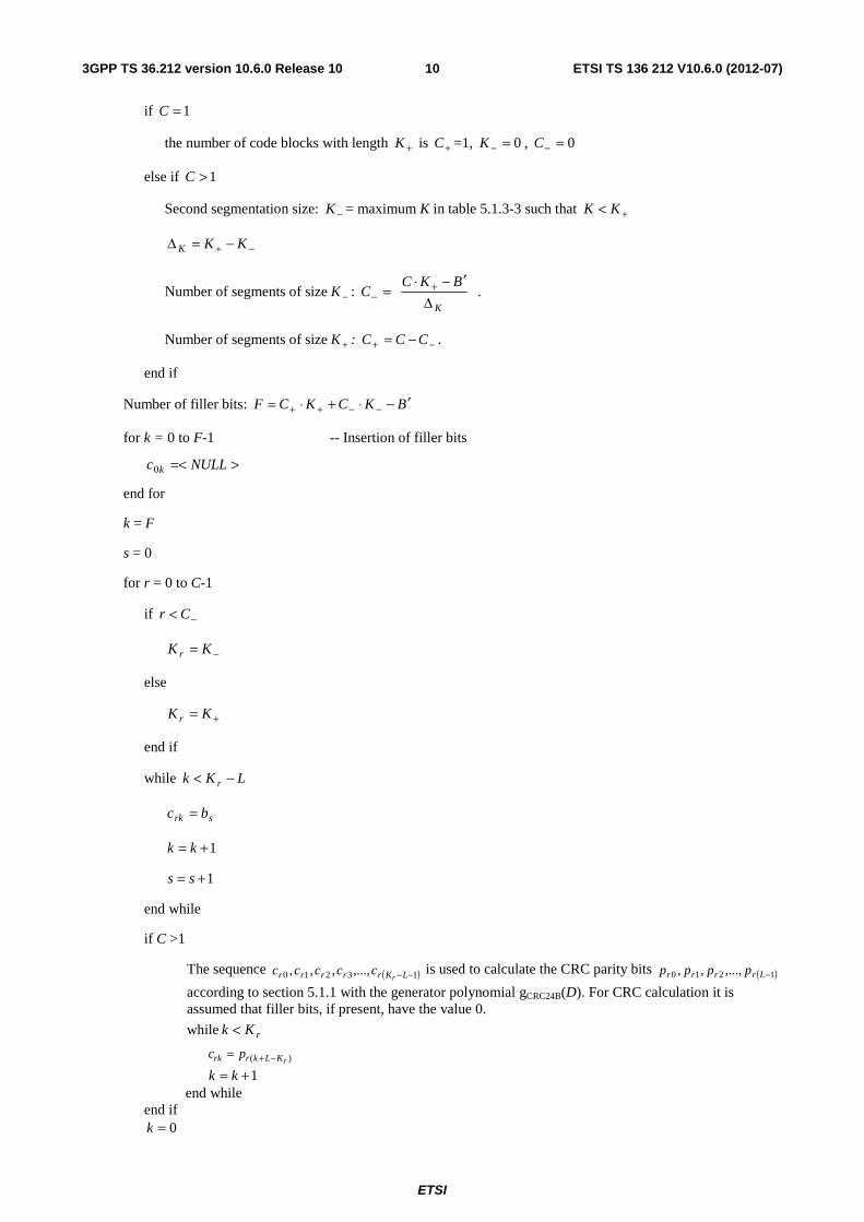
ETSI
ETSI TS 136 212 V1060 (2012-07)103GPP TS 36212 version 1060 Release 10
if 1=C
the number of code blocks with length +K is +C =1 0=minusK 0=minusC
else if 1gtC
Second segmentation size minusK = maximum K in table 513-3 such that +lt KK
minus+ minus=Δ KKK
Number of segments of size minusK ⎥⎦
⎥⎢⎣
⎢
Δprimeminussdot
= +minus
K
BKCC
Number of segments of size +K minus+ minus= CCC
end if
Number of filler bits BKCKCF primeminussdot+sdot= minusminus++
for k = 0 to F-1 -- Insertion of filler bits
gt=lt NULLc k0
end for
k = F
s = 0
for r = 0 to C-1
if minuslt Cr
minus= KK r
else
+= KK r
end if
while LKk r minuslt
srk bc =
1+= kk
1+= ss
end while
if C gt1
The sequence ( )13210 minusminusLKrrrrr rccccc is used to calculate the CRC parity bits ( )1210 minusLrrrr pppp
according to section 511 with the generator polynomial gCRC24B(D) For CRC calculation it is assumed that filler bits if present have the value 0
while rKk lt
)( rKLkrrk pc minus+=
1+= kk end while
end if 0=k
ETSI
ETSI TS 136 212 V1060 (2012-07)113GPP TS 36212 version 1060 Release 10
end for
513 Channel coding
The bit sequence input for a given code block to channel coding is denoted by 13210 minusKccccc where K is the
number of bits to encode After encoding the bits are denoted by )(1
)(3
)(2
)(1
)(0 i
Diiii ddddd minus where D is the number of
encoded bits per output stream and i indexes the encoder output stream The relation between kc and )(ikd and between
K and D is dependent on the channel coding scheme
The following channel coding schemes can be applied to TrCHs
- tail biting convolutional coding
- turbo coding
Usage of coding scheme and coding rate for the different types of TrCH is shown in table 513-1 Usage of coding scheme and coding rate for the different control information types is shown in table 513-2
The values of D in connection with each coding scheme
- tail biting convolutional coding with rate 13 D = K
- turbo coding with rate 13 D = K + 4
The range for the output stream index i is 0 1 and 2 for both coding schemes
Table 513-1 Usage of channel coding scheme and coding rate for TrCHs
TrCH Coding scheme Coding rate UL-SCH
Turbo coding 13 DL-SCH
PCH MCH
BCH Tail biting
convolutional coding
13
Table 513-2 Usage of channel coding scheme and coding rate for control information
Control Information Coding scheme Coding rate
DCI Tail biting
convolutional coding
13
CFI Block code 116 HI Repetition code 13
UCI
Block code variable Tail biting
convolutional coding
13
5131 Tail biting convolutional coding
A tail biting convolutional code with constraint length 7 and coding rate 13 is defined
The configuration of the convolutional encoder is presented in figure 513-1
The initial value of the shift register of the encoder shall be set to the values corresponding to the last 6 information bits in the input stream so that the initial and final states of the shift register are the same Therefore denoting the shift register of the encoder by 5210 ssss then the initial value of the shift register shall be set to
ETSI
ETSI TS 136 212 V1060 (2012-07)123GPP TS 36212 version 1060 Release 10
( )iKi cs minusminus= 1
kc
)0(kd
)1(kd
)2(kd
Figure 513-1 Rate 13 tail biting convolutional encoder
The encoder output streams )0(kd )1(
kd and )2(kd correspond to the first second and third parity streams respectively as
shown in Figure 513-1
5132 Turbo coding
51321 Turbo encoder
The scheme of turbo encoder is a Parallel Concatenated Convolutional Code (PCCC) with two 8-state constituent encoders and one turbo code internal interleaver The coding rate of turbo encoder is 13 The structure of turbo encoder is illustrated in figure 513-2
The transfer function of the 8-state constituent code for the PCCC is
G(D) = ⎥⎦
⎤⎢⎣
⎡
)(
)(1
0
1
Dg
Dg
where
g0(D) = 1 + D2 + D3
g1(D) = 1 + D + D3
The initial value of the shift registers of the 8-state constituent encoders shall be all zeros when starting to encode the input bits
The output from the turbo encoder is
kk xd =)0(
kk zd =)1(
kk zd prime=)2(
for 1210 minus= Kk
If the code block to be encoded is the 0-th code block and the number of filler bits is greater than zero ie F gt 0 then
the encoder shall set ck = 0 k = 0hellip(F-1) at its input and shall set gt=lt NULLd k)0( k = 0hellip(F-1) and
gt=lt NULLd k)1( k = 0hellip(F-1) at its output
The bits input to the turbo encoder are denoted by 13210 minusKccccc and the bits output from the first and second 8-
state constituent encoders are denoted by 13210 minusKzzzzz and 13210 minusprimeprimeprimeprimeprime Kzzzzz respectively The bits output
from the turbo code internal interleaver are denoted by 110 minusprimeprimeprime Kccc and these bits are to be the input to the second 8-
state constituent encoder
ETSI
ETSI TS 136 212 V1060 (2012-07)133GPP TS 36212 version 1060 Release 10
kc
kcprime
kxprime
kx
kz
kzprime
Figure 513-2 Structure of rate 13 turbo encoder (dotted lines apply for trellis termination only)
51322 Trellis termination for turbo encoder
Trellis termination is performed by taking the tail bits from the shift register feedback after all information bits are encoded Tail bits are padded after the encoding of information bits
The first three tail bits shall be used to terminate the first constituent encoder (upper switch of figure 513-2 in lower position) while the second constituent encoder is disabled The last three tail bits shall be used to terminate the second constituent encoder (lower switch of figure 513-2 in lower position) while the first constituent encoder is disabled
The transmitted bits for trellis termination shall then be
KK xd =)0( 1)0(1 ++ = KK zd KK xd prime=+
)0(2 1
)0(3 ++ prime= KK zd
KK zd =)1( 2)1(
1 ++ = KK xd KK zd prime=+)1(
2 2)1(
3 ++ prime= KK xd
1)2(
+= KK xd 2)2(1 ++ = KK zd 1
)2(2 ++ prime= KK xd 2
)2(3 ++ prime= KK zd
51323 Turbo code internal interleaver
The bits input to the turbo code internal interleaver are denoted by 110 minusKccc where K is the number of input bits
The bits output from the turbo code internal interleaver are denoted by 110 minusprimeprimeprime Kccc
The relationship between the input and output bits is as follows
ETSI
ETSI TS 136 212 V1060 (2012-07)143GPP TS 36212 version 1060 Release 10
( )ii cc Π=prime i=0 1hellip (K-1)
where the relationship between the output index i and the input index )(iΠ satisfies the following quadratic form
( ) Kififi mod)( 221 sdot+sdot=Π
The parameters 1f and 2f depend on the block size K and are summarized in Table 513-3
Table 513-3 Turbo code internal interleaver parameters
i K 1f 2f i K 1f 2f i K 1f 2f i K 1f 2f
1 40 3 10 48 416 25 52 95 1120 67 140 142 3200 111 240 2 48 7 12 49 424 51 106 96 1152 35 72 143 3264 443 204 3 56 19 42 50 432 47 72 97 1184 19 74 144 3328 51 104 4 64 7 16 51 440 91 110 98 1216 39 76 145 3392 51 212 5 72 7 18 52 448 29 168 99 1248 19 78 146 3456 451 192 6 80 11 20 53 456 29 114 100 1280 199 240 147 3520 257 220 7 88 5 22 54 464 247 58 101 1312 21 82 148 3584 57 336 8 96 11 24 55 472 29 118 102 1344 211 252 149 3648 313 228 9 104 7 26 56 480 89 180 103 1376 21 86 150 3712 271 232
10 112 41 84 57 488 91 122 104 1408 43 88 151 3776 179 236 11 120 103 90 58 496 157 62 105 1440 149 60 152 3840 331 120 12 128 15 32 59 504 55 84 106 1472 45 92 153 3904 363 244 13 136 9 34 60 512 31 64 107 1504 49 846 154 3968 375 248 14 144 17 108 61 528 17 66 108 1536 71 48 155 4032 127 168 15 152 9 38 62 544 35 68 109 1568 13 28 156 4096 31 64 16 160 21 120 63 560 227 420 110 1600 17 80 157 4160 33 130 17 168 101 84 64 576 65 96 111 1632 25 102 158 4224 43 264 18 176 21 44 65 592 19 74 112 1664 183 104 159 4288 33 134 19 184 57 46 66 608 37 76 113 1696 55 954 160 4352 477 408 20 192 23 48 67 624 41 234 114 1728 127 96 161 4416 35 138 21 200 13 50 68 640 39 80 115 1760 27 110 162 4480 233 280 22 208 27 52 69 656 185 82 116 1792 29 112 163 4544 357 142 23 216 11 36 70 672 43 252 117 1824 29 114 164 4608 337 480 24 224 27 56 71 688 21 86 118 1856 57 116 165 4672 37 146 25 232 85 58 72 704 155 44 119 1888 45 354 166 4736 71 444 26 240 29 60 73 720 79 120 120 1920 31 120 167 4800 71 120 27 248 33 62 74 736 139 92 121 1952 59 610 168 4864 37 152 28 256 15 32 75 752 23 94 122 1984 185 124 169 4928 39 462 29 264 17 198 76 768 217 48 123 2016 113 420 170 4992 127 234 30 272 33 68 77 784 25 98 124 2048 31 64 171 5056 39 158 31 280 103 210 78 800 17 80 125 2112 17 66 172 5120 39 80 32 288 19 36 79 816 127 102 126 2176 171 136 173 5184 31 96 33 296 19 74 80 832 25 52 127 2240 209 420 174 5248 113 902 34 304 37 76 81 848 239 106 128 2304 253 216 175 5312 41 166 35 312 19 78 82 864 17 48 129 2368 367 444 176 5376 251 336 36 320 21 120 83 880 137 110 130 2432 265 456 177 5440 43 170 37 328 21 82 84 896 215 112 131 2496 181 468 178 5504 21 86 38 336 115 84 85 912 29 114 132 2560 39 80 179 5568 43 174 39 344 193 86 86 928 15 58 133 2624 27 164 180 5632 45 176 40 352 21 44 87 944 147 118 134 2688 127 504 181 5696 45 178 41 360 133 90 88 960 29 60 135 2752 143 172 182 5760 161 120 42 368 81 46 89 976 59 122 136 2816 43 88 183 5824 89 182 43 376 45 94 90 992 65 124 137 2880 29 300 184 5888 323 184 44 384 23 48 91 1008 55 84 138 2944 45 92 185 5952 47 186 45 392 243 98 92 1024 31 64 139 3008 157 188 186 6016 23 94 46 400 151 40 93 1056 17 66 140 3072 47 96 187 6080 47 190 47 408 155 102 94 1088 171 204 141 3136 13 28 188 6144 263 480
ETSI
ETSI TS 136 212 V1060 (2012-07)153GPP TS 36212 version 1060 Release 10
514 Rate matching
5141 Rate matching for turbo coded transport channels
The rate matching for turbo coded transport channels is defined per coded block and consists of interleaving the three
information bit streams )0(kd )1(
kd and )2(kd followed by the collection of bits and the generation of a circular buffer as
depicted in Figure 514-1 The output bits for each code block are transmitted as described in section 51412
)0(kd
)1(kd
)2(kd
ke
)0(kv
)1(kv
)2(kv
kw
Figure 514-1 Rate matching for turbo coded transport channels
The bit stream )0(kd is interleaved according to the sub-block interleaver defined in section 51411 with an output
sequence defined as )0(1
)0(2
)0(1
)0(0 minusΠKvvvv and where ΠK is defined in section 51411
The bit stream )1(kd is interleaved according to the sub-block interleaver defined in section 51411 with an output
sequence defined as )1(1
)1(2
)1(1
)1(0 minusΠKvvvv
The bit stream )2(kd is interleaved according to the sub-block interleaver defined in section 51411 with an output
sequence defined as )2(1
)2(2
)2(1
)2(0 minusΠKvvvv
The sequence of bits ke for transmission is generated according to section 51412
51411 Sub-block interleaver
The bits input to the block interleaver are denoted by )(1
)(2
)(1
)(0 i
Diii dddd minus where D is the number of bits The output
bit sequence from the block interleaver is derived as follows
(1) Assign 32=TCsubblockC to be the number of columns of the matrix The columns of the matrix are numbered 0 1
2hellip 1minusTCsubblockC from left to right
(2) Determine the number of rows of the matrix TCsubblockR by finding minimum integer TC
subblockR such that
( )TCsubblock
TCsubblock CRD timesle
The rows of rectangular matrix are numbered 0 1 2hellip 1minusTCsubblockR from top to bottom
ETSI
ETSI TS 136 212 V1060 (2012-07)163GPP TS 36212 version 1060 Release 10
(3) If ( ) DCR TCsubblock
TCsubblock gttimes then ( )DCRN TC
subblockTCsubblockD minustimes= dummy bits are padded such that yk = ltNULLgt
for k = 0 1hellip ND - 1 Then )(ikkN dy
D=+ k = 0 1hellip D-1 and the bit sequence yk is written into
the ( )TCsubblock
TCsubblock CR times matrix row by row starting with bit y0 in column 0 of row 0
⎥⎥⎥⎥⎥
⎦
⎤
⎢⎢⎢⎢⎢
⎣
⎡
minustimes+timesminus+timesminustimesminus
minus++
minus
)1(2)1(1)1()1(
1221
1210
TCsubblock
TCsubblock
TCsubblock
TCsubblock
TCsubblock
TCsubblock
TCsubblock
TCsubblock
TCsubblock
TCsubblock
TCsubblock
TCsubblock
TCsubblock
CRCRCRCR
CCCC
C
yyyy
yyyy
yyyy
L
MOMMM
L
L
For )0(kd and )1(
kd
(4) Perform the inter-column permutation for the matrix based on the pattern ( ) 110 minusisin TCsubblockCj
jP that is shown in
table 514-1 where P(j) is the original column position of the j-th permuted column After permutation of the
columns the inter-column permuted ( )TCsubblock
TCsubblock CR times matrix is equal to
⎥⎥⎥⎥⎥
⎦
⎤
⎢⎢⎢⎢⎢
⎣
⎡
timesminus+minustimesminus+timesminus+timesminus+
+minus+++
minus
TCsubblock
TCsubblock
TCsubblock
TCsubblock
TCsubblock
TCsubblock
TCsubblock
TCsubblock
TCsubblock
TCsubblock
TCsubblock
TCsubblock
TCsubblock
TCsubblock
TCsubblock
CRCPCRPCRPCRP
CCPCPCPCP
CPPPP
yyyy
yyyy
yyyy
)1()1()1()2()1()1()1()0(
)1()2()1()0(
)1()2()1()0(
L
MOMMM
L
L
(5) The output of the block interleaver is the bit sequence read out column by column from the inter-column
permuted ( )TCsubblock
TCsubblock CR times matrix The bits after sub-block interleaving are denoted
by )(1
)(2
)(1
)(0 i
Kiii vvvv minusΠ
where )(0iv corresponds to )0(Py )(
1iv to TC
subblockCPy
+)0(hellip
and ( )TCsubblock
TCsubblock CRK times=Π
For )2(kd
(4) The output of the sub-block interleaver is denoted by )2(1
)2(2
)2(1
)2(0 minusΠKvvvv where )(
)2(kk yv π= and where
( ) Π⎟⎟
⎠
⎞
⎜⎜
⎝
⎛+times+
⎟⎟
⎠
⎞
⎜⎜
⎝
⎛
⎥⎥⎦
⎥
⎢⎢⎣
⎢= KRkC
R
kPk TC
subblockTCsubblockTC
subblock
mod1mod)(π
The permutation function P is defined in Table 514-1
Table 514-1 Inter-column permutation pattern for sub-block interleaver
Number of columns TCsubblockC
Inter-column permutation pattern
gtminuslt )1()1()0( TCsubblockCPPP
32 lt 0 16 8 24 4 20 12 28 2 18 10 26 6 22 14 30 1 17 9 25 5 21 13 29 3 19 11 27 7 23 15 31 gt
51412 Bit collection selection and transmission
The circular buffer of length Π= KK w 3 for the r-th coded block is generated as follows
)0(kk vw = for k = 0hellip 1minusΠK
)1(2 kkK vw =+Π
for k = 0hellip 1minusΠK
ETSI
ETSI TS 136 212 V1060 (2012-07)173GPP TS 36212 version 1060 Release 10
)2(12 kkK vw =++Π
for k = 0hellip 1minusΠK
Denote the soft buffer size for the transport block by NIR bits and the soft buffer size for the r-th code block by Ncb bits The size Ncb is obtained as follows where C is the number of code blocks computed in section 512
- ⎟⎟⎠
⎞⎜⎜⎝
⎛⎥⎦
⎥⎢⎣
⎢= wIR
cb KC
NN min for DL-SCH and PCH transport channels
- wcb KN = for UL-SCH and MCH transport channels
where NIR is equal to
( )⎥⎥⎦⎥
⎢⎢⎣
⎢
sdotsdot=
limitDL_HARQMIMO min MMKK
NN
C
softIR
where
If the UE signals ue-Category-v10xy and is configured with transmission mode 9 for the DL cell Nsoft is the total number of soft channel bits [4] according to the UE category indicated by ue-Category-v10xy [6] Otherwise Nsoft is the total number of soft channel bits [4] according to the UE category indicated by ue-Category [6]
If Nsoft = 35982720
KC= 5
elseif Nsoft = 3654144 and the UE is capable of supporting no more than a maximum of two spatial layers for the DL cell
KC = 2
else
KC = 1
End if
KMIMO is equal to 2 if the UE is configured to receive PDSCH transmissions based on transmission modes 3 4 8 or 9 as defined in section 71 of [3] and is equal to 1 otherwise
MDL_HARQ is the maximum number of DL HARQ processes as defined in section 7 of [3]
Mlimit is a constant equal to 8
Denoting by E the rate matching output sequence length for the r-th coded block and rvidx the redundancy version number for this transmission (rvidx = 0 1 2 or 3) the rate matching output bit sequence is ke k = 01 1minusE
Define by G the total number of bits available for the transmission of one transport block
Set ( )mL QNGG sdot=prime where Qm is equal to 2 for QPSK 4 for 16QAM and 6 for 64QAM and where
- For transmit diversity
- NL is equal to 2
- Otherwise
- NL is equal to the number of layers a transport block is mapped onto
Set CG modprime=γ where C is the number of code blocks computed in section 512
if 1minusminusle γCr
set ⎣ ⎦CGQNE mL primesdotsdot=
ETSI
ETSI TS 136 212 V1060 (2012-07)183GPP TS 36212 version 1060 Release 10
else
set ⎡ ⎤CGQNE mL primesdotsdot=
end if
Set⎟⎟
⎠
⎞
⎜⎜
⎝
⎛+sdot
⎥⎥⎥
⎤
⎢⎢⎢
⎡sdotsdot= 2
820 idxTC
subblock
cbTCsubblock rv
R
NRk where TC
subblockR is the number of rows defined in section 51411
Set k = 0 and j = 0
while k lt E
if gtnelt+ NULLwcbNjk mod)( 0
cbNjkk we mod)( 0 +=
k = k +1
end if
j = j +1
end while
5142 Rate matching for convolutionally coded transport channels and control information
The rate matching for convolutionally coded transport channels and control information consists of interleaving the
three bit streams )0(kd )1(
kd and )2(kd followed by the collection of bits and the generation of a circular buffer as
depicted in Figure 514-2 The output bits are transmitted as described in section 51422
)0(kd
)1(kd
)2(kd
ke
)0(kv
)1(kv
)2(kv
kw
Figure 514-2 Rate matching for convolutionally coded transport channels and control information
The bit stream )0(kd is interleaved according to the sub-block interleaver defined in section 51421 with an output
sequence defined as )0(1
)0(2
)0(1
)0(0 minusΠKvvvv and where ΠK is defined in section 51421
The bit stream )1(kd is interleaved according to the sub-block interleaver defined in section 51421 with an output
sequence defined as )1(1
)1(2
)1(1
)1(0 minusΠKvvvv
The bit stream )2(kd is interleaved according to the sub-block interleaver defined in section 51421 with an output
sequence defined as )2(1
)2(2
)2(1
)2(0 minusΠKvvvv
ETSI
ETSI TS 136 212 V1060 (2012-07)193GPP TS 36212 version 1060 Release 10
The sequence of bits ke for transmission is generated according to section 51422
51421 Sub-block interleaver
The bits input to the block interleaver are denoted by )(1
)(2
)(1
)(0 i
Diii dddd minus where D is the number of bits The output
bit sequence from the block interleaver is derived as follows
(1) Assign 32=CCsubblockC to be the number of columns of the matrix The columns of the matrix are numbered 0 1
2hellip 1minusCCsubblockC from left to right
(2) Determine the number of rows of the matrix CCsubblockR by finding minimum integer CC
subblockR such that
( )CCsubblock
CCsubblock CRD timesle
The rows of rectangular matrix are numbered 0 1 2hellip 1minusCCsubblockR from top to bottom
(3) If ( ) DCR CCsubblock
CCsubblock gttimes then ( )DCRN CC
subblockCCsubblockD minustimes= dummy bits are padded such that yk = ltNULLgt
for k = 0 1hellip ND - 1 Then )(ikkN dy
D=+ k = 0 1hellip D-1 and the bit sequence yk is written into
the ( )CCsubblock
CCsubblock CR times matrix row by row starting with bit y0 in column 0 of row 0
⎥⎥⎥⎥⎥
⎦
⎤
⎢⎢⎢⎢⎢
⎣
⎡
minustimes+timesminus+timesminustimesminus
minus++
minus
)1(2)1(1)1()1(
1221
1210
CCsubblock
CCsubblock
CCsubblock
CCsubblock
CCsubblock
CCsubblock
CCsubblock
CCsubblock
CCsubblock
CCsubblock
CCsubblock
CCsubblock
CCsubblock
CRCRCRCR
CCCC
C
yyyy
yyyy
yyyy
L
MOMMM
L
L
(4) Perform the inter-column permutation for the matrix based on the pattern ( ) 110 minusisin CCsubblockCj
jP that is shown in
table 514-2 where P(j) is the original column position of the j-th permuted column After permutation of the
columns the inter-column permuted ( )CCsubblock
CCsubblock CR times matrix is equal to
⎥⎥⎥⎥⎥
⎦
⎤
⎢⎢⎢⎢⎢
⎣
⎡
timesminus+minustimesminus+timesminus+timesminus+
+minus+++
minus
CCsubblock
CCsubblock
CCsubblock
CCsubblock
CCsubblock
CCsubblock
CCsubblock
CCsubblock
CCsubblock
CCsubblock
CCsubblock
CCsubblock
CCsubblock
CCsubblock
CCsubblock
CRCPCRPCRPCRP
CCPCPCPCP
CPPPP
yyyy
yyyy
yyyy
)1()1()1()2()1()1()1()0(
)1()2()1()0(
)1()2()1()0(
L
MOMMM
L
L
(5) The output of the block interleaver is the bit sequence read out column by column from the inter-column
permuted ( )CCsubblock
CCsubblock CR times matrix The bits after sub-block interleaving are denoted by )(
1)(
2)(
1)(
0 iK
iii vvvv minusΠ
where )(0iv corresponds to )0(Py )(
1iv to CC
subblockCPy
+)0(hellip and ( )CC
subblockCCsubblock CRK times=Π
Table 514-2 Inter-column permutation pattern for sub-block interleaver
Number of columns CCsubblockC
Inter-column permutation pattern
gtminuslt )1()1()0( CCsubblockCPPP
32 lt 1 17 9 25 5 21 13 29 3 19 11 27 7 23 15 31 0 16 8 24 4 20 12 28 2 18 10 26 6 22 14 30 gt
This block interleaver is also used in interleaving PDCCH modulation symbols In that case the input bit sequence consists of PDCCH symbol quadruplets [2]
ETSI
ETSI TS 136 212 V1060 (2012-07)203GPP TS 36212 version 1060 Release 10
51422 Bit collection selection and transmission
The circular buffer of length Π= KK w 3 is generated as follows
)0(kk vw = for k = 0hellip 1minusΠK
)1(kkK vw =+Π
for k = 0hellip 1minusΠK
)2(2 kkK vw =+Π
for k = 0hellip 1minusΠK
Denoting by E the rate matching output sequence length the rate matching output bit sequence is ke k = 01 1minusE
Set k = 0 and j = 0
while k lt E
if gtnelt NULLwwKj mod
wKjk we mod=
k = k +1
end if
j = j +1
end while
515 Code block concatenation
The input bit sequence for the code block concatenation block are the sequences rke for 10 minus= Cr and
10 minus= rEk The output bit sequence from the code block concatenation block is the sequence kf for
10 minus= Gk
The code block concatenation consists of sequentially concatenating the rate matching outputs for the different code blocks Therefore
Set 0=k and 0=r
while Cr lt
Set 0=j
while rEj lt
rjk ef =
1+= kk
1+= jj
end while
1+= rr
end while
ETSI
ETSI TS 136 212 V1060 (2012-07)213GPP TS 36212 version 1060 Release 10
52 Uplink transport channels and control information
521 Random access channel
The sequence index for the random access channel is received from higher layers and is processed according to [2]
522 Uplink shared channel
Figure 522-1 shows the processing structure for the UL-SCH transport channel on one UL cell Data arrives to the coding unit in the form of a maximum of two transport blocks every transmission time interval (TTI) per UL cell The following coding steps can be identified for each transport block of an UL cell
minus Add CRC to the transport block
minus Code block segmentation and code block CRC attachment
minus Channel coding of data and control information
minus Rate matching
minus Code block concatenation
minus Multiplexing of data and control information
minus Channel interleaver
The coding steps for one UL-SCH transport block are shown in the figure below The same general processing applies for each UL-SCH transport block on each UL cell with restrictions as specified in [3]
ETSI
ETSI TS 136 212 V1060 (2012-07)223GPP TS 36212 version 1060 Release 10
Transport block
CRC attachment
Code block segmentation
Code block CRC attachment
Channel coding
Rate matching
Code block
concatenation
Data and Control multiplexing
Channel
coding
110 Aaaa
110 Bbbb
110
rKrrr
ccc
)(1
)(1
)(0
i
Dr
i
r
i
rr
ddd
110
rErrr
eee
110 Gfff
Channel Interleaver
10 hh
Channel
coding
Channel
coding
1L RIH N Qh + sdot minus
0 1 1
RI
RI RI RI
Qq q q
prime minus 0 1 1
ACK
ACK ACK ACK
Qq q q
prime minus
0 1 1[ ]RI
RI RI RI
Oo o o
minusL
0 1 1[ ]ACK
ACK ACK ACK
Oo o o
minusL0 1 1[ ]Oo o o minusL
0 1 1 L CQIN Qq q q sdot minusL
0 1 1
Hg g g
primeminus
Figure 522-1 Transport block processing for UL-SCH
5221 Transport block CRC attachment
Error detection is provided on each UL-SCH transport block through a Cyclic Redundancy Check (CRC)
The entire transport block is used to calculate the CRC parity bits Denote the bits in a transport block delivered to layer 1 by 13210 minusAaaaaa and the parity bits by 13210 minusLppppp A is the size of the transport block and L is the
number of parity bits The lowest order information bit a0 is mapped to the most significant bit of the transport block as defined in section 611 of [5]
The parity bits are computed and attached to the UL-SCH transport block according to section 511 setting L to 24 bits and using the generator polynomial gCRC24A(D)
5222 Code block segmentation and code block CRC attachment
The bits input to the code block segmentation are denoted by 13210 minusBbbbbb where B is the number of bits in the
transport block (including CRC)
ETSI
ETSI TS 136 212 V1060 (2012-07)233GPP TS 36212 version 1060 Release 10
Code block segmentation and code block CRC attachment are performed according to section 512
The bits after code block segmentation are denoted by ( )13210 minusrKrrrrr ccccc where r is the code block number
and Kr is the number of bits for code block number r
5223 Channel coding of UL-SCH
Code blocks are delivered to the channel coding block The bits in a code block are denoted by
( )13210 minusrKrrrrr ccccc where r is the code block number and Kr is the number of bits in code block number r
The total number of code blocks is denoted by C and each code block is individually turbo encoded according to section 5132
After encoding the bits are denoted by ( ))(
1)(
3)(
2)(
1)(
0 iDr
ir
ir
ir
ir r
ddddd minus with 2 and 10=i and where rD is the number of
bits on the i-th coded stream for code block number r ie 4+= rr KD
5224 Rate matching
Turbo coded blocks are delivered to the rate matching block They are denoted by ( ))(
1)(
3)(
2)(
1)(
0 iDr
ir
ir
ir
ir r
ddddd minus
with 2 and 10=i and where r is the code block number i is the coded stream index and rD is the number of bits in
each coded stream of code block number r The total number of code blocks is denoted by C and each coded block is individually rate matched according to section 5141
After rate matching the bits are denoted by ( )13210 minusrErrrrr eeeee where r is the coded block number and where
rE is the number of rate matched bits for code block number r
5225 Code block concatenation
The bits input to the code block concatenation block are denoted by ( )13210 minusrErrrrr eeeee for 10 minus= Cr and
where rE is the number of rate matched bits for the r-th code block
Code block concatenation is performed according to section 515
The bits after code block concatenation are denoted by 13210 minusGfffff where G is the total number of coded bits
for transmission of the given transport block over LN transmission layers excluding the bits used for control
transmission when control information is multiplexed with the UL-SCH transmission
5226 Channel coding of control information
Control data arrives at the coding unit in the form of channel quality information (CQI andor PMI) HARQ-ACK and rank indication Different coding rates for the control information are achieved by allocating different number of coded symbols for its transmission When control data are transmitted in the PUSCH the channel coding for HARQ-ACK rank indication and channel quality information 1210 minusOoooo is done independently
For TDD the number of HARQ-ACK bits is determined as described in section 73 of [3]
When the UE transmits HARQ-ACK bits or rank indicator bits it shall determine the number of coded modulation symbols per layer Qprime for HARQ-ACK or rank indicator as follows
For the case when only one transport block is transmitted in the PUSCH conveying the HARQ-ACK bits or rank indicator bits
ETSI
ETSI TS 136 212 V1060 (2012-07)243GPP TS 36212 version 1060 Release 10
⎟⎟⎟⎟⎟
⎠
⎞
⎜⎜⎜⎜⎜
⎝
⎛
sdot
⎥⎥⎥⎥
⎥
⎤
⎢⎢⎢⎢
⎢
⎡sdotsdotsdot
=prime
summinus
=
minusminusPUSCHscC
rr
PUSCHoffset
initialPUSCHsymb
initialPUSCHsc M
K
NMOQ 4min
1
0
β
where O is the number of HARQ-ACK bits or rank indicator bits PUSCHscM is the scheduled bandwidth for PUSCH
transmission in the current sub-frame for the transport block expressed as a number of subcarriers in [2] and initial-PUSCH
symbN is the number of SC-FDMA symbols per subframe for initial PUSCH transmission for the same transport
block respectively given by ( )( )SRSULsymbsymb 12 NNN ialPUSCH-init minusminussdot= where SRSN is equal to 1 if UE transmits PUSCH
and SRS in the same subframe for initial transmission or if the PUSCH resource allocation for initial transmission even partially overlaps with the cell-specific SRS subframe and bandwidth configuration defined in section 553 of [2] or if the subframe for initial transmission is a UE-specific type-1 SRS subframe as defined in Section 82 of [3] Otherwise
SRSN is equal to 0 initialPUSCHscM minus C and rK are obtained from the initial PDCCH for the same transport block If
there is no initial PDCCH with DCI format 0 for the same transport block initialPUSCHscM minus C and rK shall be
determined from
minus the most recent semi-persistent scheduling assignment PDCCH when the initial PUSCH for the same transport block is semi-persistently scheduled or
minus the random access response grant for the same transport block when the PUSCH is initiated by the random access response grant
For the case when two transport blocks are transmitted in the PUSCH conveying the HARQ-ACK bits or rank indicator bits
( )[ ]min4minmax QMQQ PUSCHsctemp primesdotprime=prime with
⎥⎥⎥⎥⎥
⎥
⎤
⎢⎢⎢⎢⎢
⎢
⎡
sdotsdot+sdotsdot
sdotsdotsdotsdotsdotprime
sumsumminus
=
minusminusminus
=
minusminus
minusminusminusminus
=1
0
)1()1()2(1
0
)2()2()1(
)2()2()1()1(
)2()1( C
r
initialPUSCHsymb
initialPUSCHscr
C
r
initialPUSCHsymb
initialPUSCHscr
PUSCHoffset
initialPUSCHsymb
initialPUSCHsc
initialPUSCHsymb
initialPUSCHsc
temp
NMKNMK
NMNMOQ
β
where O is the number of HARQ-ACK bits or rank indicator bits OQ =primemin if 2leO ⎡ ⎤mQOQ prime=prime 2min if 113 lele O
with ( )21 min mmm QQQ =prime where 21 =xQ xm is the modulation order of transport block ldquoxrdquo and
⎡ ⎤ ⎡ ⎤mm QOQOQ prime+prime=prime 22 21min if 11gtO with ⎡ ⎤21 OO = and ⎡ ⎤22 OOO minus= 21)(sc =xM xialPUSCH-init are the
scheduled bandwidths for PUSCH transmission in the initial sub-frame for the first and second transport block
respectively expressed as a number of subcarriers in [2] and 21(x)symb =xN ialPUSCH-init are the number of SC-FDMA
symbols per subframe for initial PUSCH transmission for the first and second transport block given by
( )( ) 2112 )(SRS
ULsymb
)(symb =minusminussdot= xNNN xxialPUSCH-init where 21)( =xN x
SRS is equal to 1 if UE transmits PUSCH and
SRS in the same subframe for initial transmission of transport block ldquoxrdquo or if the PUSCH resource allocation for initial transmission of transport bock ldquoxrdquo even partially overlaps with the cell-specific SRS subframe and bandwidth configuration defined in section 553 of [2] or if the subframe for initial transmission of transport block ldquoxrdquo is a UE-
specific type-1 SRS subframe as defined in Section 82 of [3] Otherwise 21)( =xN xSRS is equal to 0
21)( =minus xM xinitialPUSCHsc 21)( =xC x and 21)( =xK x
r are obtained from the initial PDCCH for the
corresponding transport block
For HARQ-ACK QQQ mACK primesdot= and ACKHARQoffset
PUSCHoffset
minus= ββ where mQ is the modulation order of a given
transport block and ACKHARQoffset
minusβ shall be determined according to [3] depending on the number of transmission
codewords for the corresponding PUSCH
ETSI
ETSI TS 136 212 V1060 (2012-07)253GPP TS 36212 version 1060 Release 10
For rank indication QQQ mRI primesdot= and RIoffset
PUSCHoffset ββ = where mQ is the modulation order of a given transport
block and RIoffsetβ shall be determined according to [3] depending on the number of transmission codewords for the
corresponding PUSCH
For HARQ-ACK
minus Each positive acknowledgement (ACK) is encoded as a binary lsquo1rsquo and each negative acknowledgement (NACK) is encoded as a binary lsquo0rsquo
minus If HARQ-ACK feedback consists of 1-bit of information ie ][ 0ACKo it is first encoded according to Table
5226-1
minus If HARQ-ACK feedback consists of 2-bits of information ie ] [ 10ACKACK oo with 0
ACKo corresponding to
HARQ-ACK bit for codeword 0 and ACKo1 corresponding to that for codeword 1 or if HARQ-ACK feedback
consists of 2-bits of information as a result of the aggregation of HARQ-ACK bits corresponding to two DL cells with which the UE is configured by higher layers or if HARQ-ACK feedback consists of 2-bits of information corresponding to two DL subframes for TDD it is first encoded according to Table 5226-2
where 2mod) ( 102ACKACKACK ooo +=
Table 5226-1 Encoding of 1-bit HARQ-ACK
Qm Encoded HARQ-ACK 2 y] [ 0
ACKo
4 y x x] [ 0ACKo
6 ]y x x x x [ 0ACKo
Table 5226-2 Encoding of 2-bit HARQ-ACK
Qm Encoded HARQ-ACK 2 ] [ 210210
ACKACKACKACKACKACK oooooo
4 x x] x x x x [ 210210ACKACKACKACKACKACK oooooo
6 x x x x] x x x x x x x x [ 210210ACKACKACKACKACKACK oooooo
minus If HARQ-ACK feedback consists of 113 lele ACKO bits of information as a result of the aggregation of HARQ-
ACK bits corresponding to one or more DL cells with which the UE is configured by higher layers ie ACKO
ACKACKACKooo
110 minus
then a coded bit sequence ACKACKACK qqq 3110~~ ~ is obtained by using the bit sequence
ACKO
ACKACKACKooo
110 minus
as the input to the channel coding block described in section 52264 In turn the bit
sequence ACKQ
ACKACKACKACK
qqqq 1210 minus is obtained by the circular repetition of the bit sequence
ACKACKACK qqq 3110~~ ~ so that the total bit sequence length is equal to ACKQ
minus If HARQ-ACK feedback consists of 2011 lelt ACKO bits of information as a result of the aggregation of
HARQ-ACK bits corresponding to one or more DL cells with which the UE is configured by higher layers
ie ACKO
ACKACKACKooo
110 minus
then the coded bit sequence ACKQ
ACKACKACKACK
qqqq 1210 minus is obtained by using
the bit sequence ACKO
ACKACKACKooo
110 minus
as the input to the channel coding block described in section 52265
The ldquoxrdquo and ldquoyrdquo in Table 5226-1 and 5226-2 are placeholders for [2] to scramble the HARQ-ACK bits in a way that maximizes the Euclidean distance of the modulation symbols carrying HARQ-ACK information
ETSI
ETSI TS 136 212 V1060 (2012-07)263GPP TS 36212 version 1060 Release 10
For FDD or TDD HARQ-ACK multiplexing when HARQ-ACK consists of one or two bits of information the bit
sequence ACKQ
ACKACKACKACK
qqqq 1210 minus is obtained by concatenation of multiple encoded HARQ-ACK blocks where
ACKQ is the total number of coded bits for all the encoded HARQ-ACK blocks The last concatenation of the encoded
HARQ-ACK block may be partial so that the total bit sequence length is equal to ACKQ
For FDD when HARQ ACK consists of 2 or more bits of information as a result of the aggregation of more than one
DL cell the bit sequence ACKO
ACKACKACKooo
110 minus
is the result of the concatenation of HARQ-ACK bits for the multiple
DL cells according to the following pseudo-code
Set c = 0 ndash cell index lower indices correspond to lower RRC indices of corresponding cell
Set j = 0 ndash HARQ-ACK bit index
Set DLcellsN to the number of cells configured by higher layers for the UE
while c lt DLcellsN
if transmission mode configured in cell 76521isinc ndash 1 bit HARQ-ACK feedback for this cell
=ACKjo HARQ-ACK bit of this cell
j = j + 1
else
=ACKjo HARQ-ACK bit corresponding to the first codeword of this cell
j = j + 1
=ACKjo HARQ-ACK bit corresponding to the second codeword of this cell
j = j + 1
end if
c = c + 1
end while
For TDD when HARQ ACK is for the aggregation of one or more DL cells and the UE is configured with PUCCH
Format 3 [3] the bit sequence ACKO
ACKACKACKooo
110 minus
is the result of the concatenation of HARQ-ACK bits for the one
or more DL cells configured by higher layers and the multiple subframes as defined in [3]
Define DLcellsN as the number of cells configured by higher layers for the UE and DL
cB as the number of downlink
subframes for which the UE needs to feedback HARQ-ACK bits as defined in Section 73 of [3]
The number of HARQ-ACK bits for the UE to convey if it is configured with PUCCH Format 3 is computed as follows
Set k = 0 ndash counter of HARQ-ACK bits
Set c=0 ndash cell index lower indices correspond to lower RRC indices of corresponding cell
while c lt DLcellsN
set l = 0
while l lt DLcB
if transmission mode configured in cell 76521isinc -- 1 bit HARQ-ACK feedback for this cell
ETSI
ETSI TS 136 212 V1060 (2012-07)273GPP TS 36212 version 1060 Release 10
k = k + 1
else
k = k + 2
end if
l = l+1
end while
c = c + 1
end while
If k le 20 the multiplexing of HARQ-ACK bits is performed according to the following pseudo-code
Set c = 0 ndash cell index lower indices correspond to lower RRC indices of corresponding cell
Set j = 0 ndash HARQ-ACK bit index
while c lt DLcellsN
set l = 0
while l lt DLcB
if transmission mode configured in cell 76521isinc -- 1 bit HARQ-ACK feedback for this cell
ACK
lcACKj oo
~ = HARQ-ACK bit of this cell as defined in Section 73 of [3]
j = j + 1
else
][]~~[ 1221ACK
lcACK
lcACKj
ACKj oooo ++ = HARQ-ACK bits of this cell as defined in Section 73 of [3]
j = j + 2
end if
l = l+1
end while
c = c + 1
end while
If k gt 20 spatial bundling is applied to all subframes in all cells and the multiplexing of HARQ-ACK bits is performed according to the following pseudo-code
Set c = 0 ndash cell index lower indices correspond to lower RRC indices of corresponding cell
Set j = 0 ndash HARQ-ACK bit index
while c lt DLcellsN
set l = 0
while l lt DLcB
if transmission mode configured in cell 76521isinc ndash 1 bit HARQ-ACK feedback for this cell
ETSI
ETSI TS 136 212 V1060 (2012-07)283GPP TS 36212 version 1060 Release 10
ACK
lcACKj oo
~ = HARQ-ACK bit of this cell as defined in Section 73 of [3]
j = j + 1
else
ACKlc
ACKj oo
~ = binary AND operation of the HARQ-ACK bits corresponding to the first and second
codewords of this cell as defined in Section 73 of [3]
j = j + 1
end if
l = l+1
end while
c = c + 1
end while
For 11leACKO the bit sequence ACK
OACKACK
ACKooo110
minus is obtained by setting ACK ACK
i io o=
For 2011 lelt ACKO the bit sequence ACK
OACKACK
ACKooo110
minus is obtained by setting 2
ACK ACKi io o= if i is even and
2 ( 1) 2ACK
ACK ACKiO i
o o⎡ ⎤+ minus⎢ ⎥
= if i is odd
For TDD when HARQ ACK is for the aggregation of two DL cells and the UE is configured with PUCCH format 1b
with channel selection the bit sequence ACKO
ACKACKACKooo
110 minus
is obtained as described in section 73 of [3]
For TDD HARQ-ACK bundling a bit sequence ACKQ
ACKACKACK
ACKqqqq 1210~~~~
minus is obtained by concatenation of
multiple encoded HARQ-ACK blocks where ACKQ is the total number of coded bits for all the encoded HARQ-ACK
blocks The last concatenation of the encoded HARQ-ACK block may be partial so that the total bit sequence length is
equal to ACKQ A scrambling sequence [ ]ACKACKACKACK wwww 3210 is then selected from Table 5226-A with index
( ) 4mod1minus= bundledNi where bundledN is determined as described in section 73 of [3] The bit sequence ACKQ
ACKACKACKACK
qqqq 1210 minus is then generated by setting 1=m if HARQ-ACK consists of 1-bit and 3=m if
HARQ-ACK consists of 2-bits and then scrambling ACKQ
ACKACKACK
ACKqqqq 1210~~~~
minus as follows
Set i k to 0
while ACKQi lt
if yq ACKi =~ place-holder repetition bit
⎣ ⎦( ) 2mod~
1ACK
mkACK
iACKi wqq += minus
mkk 4mod)1( +=
else
if xq ACKi =~ a place-holder bit
ACKi
ACKi qq ~=
else coded bit
ETSI
ETSI TS 136 212 V1060 (2012-07)293GPP TS 36212 version 1060 Release 10
⎣ ⎦( ) 2mod~
ACK
mkACK
iACKi wqq +=
mkk 4mod)1( +=
end if
1+= ii
end while
Table 5226-A Scrambling sequence selection for TDD HARQ-ACK bundling
i [ ]ACKACKACKACK wwww 3210
0 [1 1 1 1] 1 [1 0 1 0] 2 [1 1 0 0] 3 [1 0 0 1]
When HARQ-ACK information is to be multiplexed with UL-SCH at a given PUSCH the HARQ-ACK information is multiplexed in all layers of all transport blocks of that PUSCH For a given transport block the vector sequence output
of the channel coding for HARQ-ACK information is denoted by ACK
Q
ACKACK
ACKqqq
110
minusprime where ACK
iq
10 minusprime= ACKQi are column vectors of length ( )Lm NQ sdot and where mACKACK QQQ =prime is obtained as follows
Set i k to 0
while ACKQi lt
] [ˆ 1ACK
QiACKi
ACK
k mqqq minus+= -- temporary row vector
T
N
ACK
k
ACK
k
ACK
k
L
qqq ]ˆˆ[4484476
L= -- replicating the row vector ACK
kq NL times and transposing into a column vector
mQii +=
1+= kk
end while
where LN is the number of layers onto which the UL-SCH transport block is mapped
For rank indication (RI) (RI only joint report of RI and i1 and joint report of RI and PTI)
minus The corresponding bit widths for RI feedback for PDSCH transmissions are given by Tables 52261-2 52262-3 52263-3 52331-3 52331-3A 52332-4 and 52332-4A which are determined assuming the maximum number of layers according to the corresponding eNodeB antenna configuration and UE category
minus If RI feedback consists of 1-bit of information ie ][ 0RIo it is first encoded according to Table 5226-3 The
][ 0RIo to RI mapping is given by Table 5226-5
minus If RI feedback consists of 2-bits of information ie ] [ 10RIRI oo with RIo0 corresponding to MSB of 2-bit input
and RIo1 corresponding to LSB it is first encoded according to Table 5226-4 where
2mod) ( 102RIRIRI ooo += The ] [ 10
RIRI oo to RI mapping is given by Table 5226-6
ETSI
ETSI TS 136 212 V1060 (2012-07)303GPP TS 36212 version 1060 Release 10
Table 5226-3 Encoding of 1-bit RI
Qm Encoded RI 2 y] [ 0
RIo
4 y x x] [ 0RIo
6 ]y x x x x [ 0RIo
Table 5226-4 Encoding of 2-bit RI
Qm Encoded RI 2 ] [ 210210
RIRIRIRIRIRI oooooo
4 x x] x x x x [ 210210RIRIRIRIRIRI oooooo
6 x x x x] x x x x x x x x [ 210210RIRIRIRIRIRI oooooo
Table 5226-5 RIo0 to RI mapping
RIo0 RI
0 1 1 2
Table 5226-6 RIo0 RIo1 to RI mapping
RIo0 RIo1 RI
0 0 1 0 1 2 1 0 3 1 1 4
Table 5226-7 RIo0 RIo1 RIo2 to RI mapping
RIo0 RIo1 RIo2 RI
0 0 0 1 0 0 1 2 0 1 0 3 0 1 1 4 1 0 0 5 1 0 1 6 1 1 0 7 1 1 1 8
minus If RI feedback for a given DL cell consists of 3-bits of information ie ] [ 210RIRIRI ooo with RIo0 corresponding
to MSB of 3-bit input and RIo2 corresponding to LSB The ]o [ 210RIRIRI oo to RI mapping is given by Table
5226-7
minus If RI feedback consists of 113 lele RIO bits of information ie ] [110
RIO
RIRIRIooo
minus then a coded bit sequence
]~~ ~[ 3110RIRIRI qqq is obtained by using the bit sequence ] [
110RIO
RIRIRIooo
minus as the input to the channel coding
block described in section 52264
ETSI
ETSI TS 136 212 V1060 (2012-07)313GPP TS 36212 version 1060 Release 10
minus If RI feedback consists of 1511 lelt RIO bits of information as a result of the aggregation of RI bits
corresponding to multiple DL cells ie ] [110
RIO
RIRIRIooo
minus then the coded bit sequence
RIQ
RIRIRIRI
qqqq 1210 minus is obtained by using the bit sequence ] [110
RIO
RIRIRIooo
minus as the input to the channel
coding block described in section 52265
The ldquoxrdquo and ldquoyrdquo in Table 5226-3 and 5226-4 are placeholders for [2] to scramble the RI bits in a way that maximizes the Euclidean distance of the modulation symbols carrying rank information
For the case where RI feedback for more than one DL cell is to be reported the RI report for each DL cell is concatenated prior to coding in increasing order of cell index
For the case where RI feedback consists of one or two bits of information the bit sequence RIQ
RIRIRIRI
qqqq 1210 minus is
obtained by concatenation of multiple encoded RI blocks where RIQ is the total number of coded bits for all the
encoded RI blocks The last concatenation of the encoded RI block may be partial so that the total bit sequence length is equal to RIQ
For the case where RI feedback consists of 113 lele RIO bits of information the bit sequence RIQ
RIRIRIRI
qqqq 1210 minus is
obtained by the circular repetition of the bit sequence RIRIRI qqq 3110~~ ~ so that the total bit sequence length is equal
to RIQ
When rank information is to be multiplexed with UL-SCH at a given PUSCH the rank information is multiplexed in all layers of all transport blocks of that PUSCH For a given transport block the vector sequence output of the channel
coding for rank information is denoted by RIQ
RIRI
RIqqq
110
minusprime where RI
iq 10 minusprime= RIQi are column vectors of
length ( )Lm NQ sdot and where mRIRI QQQ =prime The vector sequence is obtained as follows
Set i j k to 0
while RIQi lt
] [ˆ 1RI
QiRIi
RI
k mqqq minus+= -- temporary row vector
T
N
RI
k
RI
k
RI
k
L
qqq ]ˆˆ[48476
L= -- replicating the row vector RI
kq NL times and transposing into a column vector
mQii +=
1+= kk
end while
where LN is the number of layers onto which the UL-SCH transport block is mapped
For channel quality control information (CQI andor PMI denoted as CQIPMI)
When the UE transmits channel quality control information bits it shall determine the number of modulation coded symbols per layer Qprime for channel quality information as
ETSI
ETSI TS 136 212 V1060 (2012-07)323GPP TS 36212 version 1060 Release 10
⎟⎟⎟⎟⎟
⎠
⎞
⎜⎜⎜⎜⎜
⎝
⎛
minussdot
⎥⎥⎥⎥
⎥
⎤
⎢⎢⎢⎢
⎢
⎡
sdotsdotsdot+=prime
summinus
=
minusminus
)(
)(
1
0
)(
)()(
)(
min )( xm
xRIPUSCH
symbPUSCHscC
r
xr
PUSCHoffset
xinitialPUSCHsymb
xinitialPUSCHsc
Q
QNM
K
NMLOQ x
β
where O is the number of CQIPMI bits L is the number of CRC bits given by ⎩⎨⎧ le
=otherwise8
110 OL
QQQ xmCQI primesdot= )( and CQI
offsetPUSCHoffset ββ = where CQI
offsetβ shall be determined according to [3] depending on the number
of transmission codewords for the corresponding PUSCH If RI is not transmitted then 0)( =xRIQ
The variable ldquoxrdquo in )(xrK represents the transport block index corresponding to the highest IMCS value indicated by the
initial UL grant In case the two transport blocks have the same IMCS value in the corresponding initial UL grant ldquox
=1rdquo which corresponds to the first transport block )( xinitialPUSCHscM minus )( xC and )(x
rK are obtained from the initial
PDCCH for the same transport block If there is no initial PDCCH with DCI format 0 for the same transport block )( xinitialPUSCH
scM minus )( xC and )(xrK shall be determined from
minus the most recent semi-persistent scheduling assignment PDCCH when the initial PUSCH for the same transport block is semi-persistently scheduled or
minus the random access response grant for the same transport block when the PUSCH is initiated by the random access response grant
)(xinitialPUSCHsymbN minus is the number of SC-FDMA symbols per subframe for initial PUSCH transmission for the same
transport block
For UL-SCH data information ( ))()(PUSCHsc
PUSCHsymb
)( xRICQI
xm
xL QQQMNNG minusminussdotsdotsdot= where )(x
LN is the number of layers the
corresponding UL-SCH transport block is mapped onto PUSCHscM is the scheduled bandwidth for PUSCH transmission
in the current sub-frame for the transport block and PUSCHsymbN is the number of SC-FDMA symbols in the current
PUSCH transmission sub-frame given by ( )( )SRSNNN minusminussdot= 12 ULsymb
PUSCHsymb where SRSN is equal to 1 if UE transmits
PUSCH and SRS in the same subframe for the current subframe or if the PUSCH resource allocation for the current subframe even partially overlaps with the cell-specific SRS subframe and bandwidth configuration defined in section 553 of [2] or if the current subframe is a UE-specific type-1 SRS subframe as defined in Section 82 of [3] Otherwise
SRSN is equal to 0
In case of CQIPMI report for more than one DL cell 1210 minusOoooo is the result of concatenating the CQIPMI
report for each DL cell in increasing order of cell index
minus If the payload size is less than or equal to 11 bits the channel coding of the channel quality information is performed according to section 52264 with input sequence 1210 minusOoooo
minus For payload sizes greater than 11 bits the CRC attachment channel coding and rate matching of the channel quality information is performed according to sections 511 5131 and 5142 respectively The input bit sequence to the CRC attachment operation is 1210 minusOoooo The output bit sequence of the CRC
attachment operation is the input bit sequence to the channel coding operation The output bit sequence of the channel coding operation is the input bit sequence to the rate matching operation
The output sequence for the channel coding of channel quality information is denoted by 13210 minussdot CQIL QNqqqqq
where LN is the number of layers the corresponding UL-SCH transport block is mapped onto
52261 Channel quality information formats for wideband CQI reports
Table 52261-1 and Table 52261-1A show the fields and the corresponding bit widths for the channel quality information feedback for wideband reports for PDSCH transmissions associated with transmission mode 4
ETSI
ETSI TS 136 212 V1060 (2012-07)333GPP TS 36212 version 1060 Release 10
transmission mode 6 transmission mode 8 configured with PMIRI reporting and transmission mode 9 configured with PMIRI reporting with 248 antenna ports N in Table 52261-1 is defined in section 72 of [3]
Table 52261-1 Fields for channel quality information feedback for wideband CQI reports (transmission mode 4 transmission mode 6 transmission mode 8 configured with PMIRI reporting
and transmission mode 9 configured with PMIRI reporting with 24 antenna ports)
Field Bit width 2 antenna ports 4 antenna ports
Rank = 1 Rank = 2 Rank = 1 Rank gt 1 Wideband CQI codeword 0 4 4 4 4 Wideband CQI codeword 1 0 4 0 4 Precoding matrix indicator N2 N N4 N4
Table 52261-1A Fields for channel quality information feedback for wideband CQI reports (transmission mode 9 configured with PMIRI reporting with 8 antenna ports)
Field Bit width
Rank = 1 Rank = 2 Rank = 3 Rank = 4 Wideband CQI codeword 0 4 4 4 4
Wideband CQI codeword 1 0 4 4 4
Wideband first PMI i1 4 4 2 2
Subband second PMI i2 4N 4N 4N 3N
Field Bit width
Rank = 5 Rank = 6 Rank = 7 Rank = 8
Wideband CQI codeword 0 4 4 4 4
Wideband CQI codeword 1 4 4 4 4
Wideband first PMI i1 2 2 2 0
Subband second PMI i2 0 0 0 0
Table 52261-2 shows the fields and the corresponding bit width for the rank indication feedback for wideband CQI reports for PDSCH transmissions associated with transmission mode 4 transmission mode 8 configured with PMIRI reporting and transmission mode 9 configured with PMIRI reporting with 248 antenna ports
Table 52261-2 Fields for rank indication feedback for wideband CQI reports (transmission mode 4 transmission mode 8 configured with PMIRI reporting and transmission
mode 9 configured with PMIRI reporting with 248 antenna ports)
Field Bit width
2 antenna ports 4 antenna ports 8 antenna ports
Max 2 layers Max 4 layers Max 2 layers Max 4 layers Max 8 layers Rank indication 1 1 2 1 2 3
The channel quality bits in Table 52261-1 and Table 52261-1A form the bit sequence 1210 minusOoooo with 0o
corresponding to the first bit of the first field in the table 1o corresponding to the second bit of the first field in the
table and 1minusOo corresponding to the last bit in the last field in the table The field of PMI shall be in the increasing
order of the subband index [3] The first bit of each field corresponds to MSB and the last bit LSB The RI bits sequence in Table 52261-2 is encoded according to section 5226
52262 Channel quality information formats for higher layer configured subband CQI reports
Table 52262-1 shows the fields and the corresponding bit width for the channel quality information feedback for higher layer configured report for PDSCH transmissions associated with transmission mode 1 transmission mode 2 transmission mode 3 transmission mode 7 transmission mode 8 configured without PMIRI reporting and transmission
ETSI
ETSI TS 136 212 V1060 (2012-07)343GPP TS 36212 version 1060 Release 10
mode 9 configured without PMIRI reporting or configured with 1 antenna port N in Table 52262-1 is defined in section 72 of [3]
Table 52262-1 Fields for channel quality information feedback for higher layer configured subband CQI reports
(transmission mode 1 transmission mode 2 transmission mode 3 transmission mode 7 transmission mode 8 configured without PMIRI reporting and transmission mode 9 configured
without PMIRI reporting or configured with 1 antenna port)
Field Bit width
Wide-band CQI codeword 4 Subband differential CQI N2
Table 52262-2 and Table 52262-2A show the fields and the corresponding bit widths for the channel quality information feedback for higher layer configured report for PDSCH transmissions associated with transmission mode 4 transmission mode 5 transmission mode 6 transmission mode 8 configured with PMIRI reporting and transmission mode 9 configured with PMIRI reporting with 248 antenna ports N in Table 52262-2 is defined in section 72 of [3]
Table 52262-2 Fields for channel quality information feedback for higher layer configured subband CQI reports
(transmission mode 4 transmission mode 5 transmission mode 6 transmission mode 8 configured with PMIRI reporting and transmission mode 9 configured with PMIRI reporting with 24 antenna
ports)
Field Bit width 2 antenna ports 4 antenna ports
Rank = 1 Rank = 2 Rank = 1 Rank gt 1 Wide-band CQI codeword 0 4 4 4 4
Subband differential CQI codeword 0 N2 N2 N2 N2 Wide-band CQI codeword 1 0 4 0 4
Subband differential CQI codeword 1 0 N2 0 N2 Precoding matrix indicator 2 1 4 4
Table 52262-2A Fields for channel quality information feedback for higher layer configured subband CQI reports (transmission mode 9 configured with PMIRI reporting with 8 antenna ports)
Field Bitwidth
Rank = 1 Rank = 2 Rank = 3 Rank = 4 Wideband CQI codeword 0 4 4 4 4
Subband differential CQI codeword 0 N2 N2 N2 N2
Wideband CQI codeword 1 0 4 4 4 Subband differential CQI codeword 1 0 N2 N2 N2
Wideband first PMI i1 4 4 2 2 Subband second PMI i2 4 4 4 3
Field Bitwidth
Rank = 5 Rank = 6 Rank = 7 Rank = 8 Wideband CQI codeword 0 4 4 4 4
Subband differential CQI codeword 0 N2 N2 N2 N2
Wideband CQI codeword 1 4 4 4 4 Subband differential CQI codeword 1 N2 N2 N2 N2
Wideband first PMI i1 2 2 2 0 Subband second PMI i2 0 0 0 0
Table 52262-3 shows the fields and the corresponding bit width for the rank indication feedback for higher layer configured subband CQI reports for PDSCH transmissions associated with transmission mode 3 transmission mode 4
ETSI
ETSI TS 136 212 V1060 (2012-07)353GPP TS 36212 version 1060 Release 10
transmission mode 8 configured with PMIRI reporting and transmission mode 9 configured with PMIRI reporting with 248 antenna ports
Table 52262-3 Fields for rank indication feedback for higher layer configured subband CQI reports (transmission mode 3 transmission mode 4 transmission mode 8 configured with PMIRI reporting
and transmission mode 9 configured with PMIRI reporting with 248 antenna ports)
Field Bit width
2 antenna ports 4 antenna ports 8 antenna ports
Max 2 layers Max 4 layers Max 2 layers Max 4 layers Max 8 layers Rank indication 1 1 2 1 2 3
The channel quality bits in Table 52262-1 Table 52262-2 and Table 52262-2A form the bit sequence
1210 minusOoooo with 0o corresponding to the first bit of the first field in each of the tables 1o corresponding to the
second bit of the first field in each of the tables and 1minusOo corresponding to the last bit in the last field in each of the
tables The field of the PMI and subband differential CQI shall be in the increasing order of the subband index [3] The first bit of each field corresponds to MSB and the last bit LSB The RI bits sequence in Table 52262-3 is encoded according to section 5226
52263 Channel quality information formats for UE selected subband CQI reports
Table 52263-1 shows the fields and the corresponding bit widths for the channel quality information feedback for UE selected subband CQI for PDSCH transmissions associated with transmission mode 1 transmission mode 2 transmission mode 3 transmission mode 7 transmission mode 8 configured without PMIRI reporting and transmission mode 9 configured without PMIRI reporting or configured with 1 antenna port L in Table 52263-1 is defined in section 72 of [3]
Table 52263-1 Fields for channel quality information feedback for UE selected subband CQI reports
(transmission mode 1 transmission mode 2 transmission mode 3 transmission mode 7 transmission mode 8 configured without PMIRI reporting and transmission mode 9 configured
without PMIRI reporting or configured with 1 antenna port)
Field Bit width
Wide-band CQI codeword 4 Subband differential CQI 2
Position of the M selected subbands L Table 52263-2 and Table 52263-2A show the fields and the corresponding bit widths for the channel quality information feedback for UE selected subband CQI for PDSCH transmissions associated with transmission mode 4 transmission mode 6 transmission mode 8 configured with PMIRI reporting and transmission mode 9 configured with PMIRI reporting with 248 antenna ports L in Table 52263-2 is defined in section 72 of [3]
Table 52263-2 Fields for channel quality information feedback for UE selected subband CQI reports
(transmission mode 4 transmission mode 6 transmission mode 8 configured with PMIRI reporting and transmission mode 9 configured with PMIRI reporting with 24 antenna ports)
Field Bit width 2 antenna ports 4 antenna ports
Rank = 1 Rank = 2 Rank = 1 Rank gt 1 Wide-band CQI codeword 0 4 4 4 4
Subband differential CQI codeword 0 2 2 2 2 Wide-band CQI codeword 1 0 4 0 4
Subband differential CQI codeword 1 0 2 0 2 Position of the M selected subbands L L L L
Precoding matrix indicator 4 2 8 8
ETSI
ETSI TS 136 212 V1060 (2012-07)363GPP TS 36212 version 1060 Release 10
Table 52263-2A Fields for channel quality information feedback for UE selected subband CQI reports (transmission mode 9 configured with PMIRI reporting with 8 antenna ports)
Field Bit width
Rank = 1
Rank = 2
Rank = 3
Rank = 4
Rank = 5
Rank = 6
Rank = 7
Rank = 8
Wide-band CQI codeword 0 4 4 4 4 4 4 4 4 Subband differential CQI
codeword 0 2 2 2 2 2 2 2 2
Wide-band CQI codeword 1 0 4 4 4 4 4 4 4 Subband differential CQI
codeword 1 0 2 2 2 2 2 2 2
Position of the M selected subbands
L L L L L L L L
Wideband first PMI i1 4 4 2 2 2 2 2 0 Wideband second PMI i2 4 4 4 3 0 0 0 0 Subband second PMI i2 4 4 4 3 0 0 0 0
Table 52263-3 shows the fields and the corresponding bit widths for the rank indication feedback for UE selected subband CQI reports for PDSCH transmissions associated with transmission mode 3 transmission mode 4 transmission mode 8 configured with PMIRI reporting and transmission mode 9 configured with PMIRI reporting with 248 antenna ports
Table 52263-3 Fields for rank indication feedback for UE selected subband CQI reports (transmission mode 3 transmission mode 4 transmission mode 8 configured with PMIRI reporting
and transmission mode 9 configured with PMIRI reporting with 248 antenna ports)
Field Bit width
2 antenna ports 4 antenna ports 8 antenna ports
Max 2 layers Max 4 layers Max 2 layers Max 4 layers Max 8 layers Rank indication 1 1 2 1 2 3
The channel quality bits in Table 52263-1 Table 52263-2 and Table 52263-2A form the bit sequence
1210 minusOoooo with 0o corresponding to the first bit of the first field in each of the tables 1o corresponding to the
second bit of the first field in each of the tables and 1minusOo corresponding to the last bit in the last field in each of the
tables The field of PMI shall start with the wideband PMI followed by the PMI for the M selected subbands The first bit of each field corresponds to MSB and the last bit LSB The RI bits sequence in Table 52263-3 is encoded according to section 5226
52264 Channel coding for CQIPMI information in PUSCH
The channel quality bits input to the channel coding block are denoted by 13210 minusOooooo where O is the
number of bits The number of channel quality bits depends on the transmission format When PUCCH-based reporting format is used the number of CQIPMI bits is defined in section 52331 for wideband reports and in section 52332 for UE selected subbands reports When PUSCH-based reporting format is used the number of CQIPMI bits is defined in section 52261 for wideband reports in section 52262 for higher layer configured subbands reports and in section 52263 for UE selected subbands reports
The channel quality information is first coded using a (32 O) block code The code words of the (32 O) block code are a linear combination of the 11 basis sequences denoted Min and defined in Table 52264-1
ETSI
ETSI TS 136 212 V1060 (2012-07)373GPP TS 36212 version 1060 Release 10
Table 52264-1 Basis sequences for (32 O) code
i Mi0 Mi1 Mi2 Mi3 Mi4 Mi5 Mi6 Mi7 Mi8 Mi9 Mi10 0 1 1 0 0 0 0 0 0 0 0 1 1 1 1 1 0 0 0 0 0 0 1 1 2 1 0 0 1 0 0 1 0 1 1 1 3 1 0 1 1 0 0 0 0 1 0 1 4 1 1 1 1 0 0 0 1 0 0 1 5 1 1 0 0 1 0 1 1 1 0 1 6 1 0 1 0 1 0 1 0 1 1 1 7 1 0 0 1 1 0 0 1 1 0 1 8 1 1 0 1 1 0 0 1 0 1 1 9 1 0 1 1 1 0 1 0 0 1 1
10 1 0 1 0 0 1 1 1 0 1 1 11 1 1 1 0 0 1 1 0 1 0 1 12 1 0 0 1 0 1 0 1 1 1 1 13 1 1 0 1 0 1 0 1 0 1 1 14 1 0 0 0 1 1 0 1 0 0 1 15 1 1 0 0 1 1 1 1 0 1 1 16 1 1 1 0 1 1 1 0 0 1 0 17 1 0 0 1 1 1 0 0 1 0 0 18 1 1 0 1 1 1 1 1 0 0 0 19 1 0 0 0 0 1 1 0 0 0 0 20 1 0 1 0 0 0 1 0 0 0 1 21 1 1 0 1 0 0 0 0 0 1 1 22 1 0 0 0 1 0 0 1 1 0 1 23 1 1 1 0 1 0 0 0 1 1 1 24 1 1 1 1 1 0 1 1 1 1 0 25 1 1 0 0 0 1 1 1 0 0 1 26 1 0 1 1 0 1 0 0 1 1 0 27 1 1 1 1 0 1 0 1 1 1 0 28 1 0 1 0 1 1 1 0 1 0 0 29 1 0 1 1 1 1 1 1 1 0 0 30 1 1 1 1 1 1 1 1 1 1 1 31 1 0 0 0 0 0 0 0 0 0 0
The encoded CQIPMI block is denoted by 13210 minusBbbbbb where 32=B and
( )summinus
=sdot=
1
0 2mod
O
nnini Mob where i = 0 1 2 hellip B-1
The output bit sequence 0 1 2 3 1 L CQIN Qq q q q q sdot minus is obtained by circular repetition of the encoded CQIPMI block as
follows
( )Bii bq mod= where i = 0 1 2 hellip NL
QCQI-1 where NL is the number of layers the corresponding UL-SCH
transport block is mapped onto
52265 Channel coding for more than 11 bits of HARQ-ACK information
The HARQ-ACK bits input to the channel coding block are denoted by ACKO
ACKACKACKooo
110 minus
where 2011 lelt ACKO
is the number of bits
The sequences of bits ⎡ ⎤ACKO
ACKACKACKACKoooo
12210 minus
and ⎡ ⎤ ⎡ ⎤ ⎡ ⎤ACKO
ACKO
ACKO
ACKO ACKACKACKACK oooo
122122
minus++ are encoded
as follows
ETSI
ETSI TS 136 212 V1060 (2012-07)383GPP TS 36212 version 1060 Release 10
( )sum
minus⎥⎥⎤
⎢⎢⎡
=sdot=
12
0 2mod~
ACKO
nni
ACKni Moq
and
⎡ ⎤sum
minus⎥⎥⎤
⎢⎢⎡minus
=+ ⎟
⎠⎞⎜
⎝⎛ sdot=
12
02
2mod~~
ACKOACKO
ACK
nni
ACKnOi Moq
where i = 0 1 2 hellip 31 and the basis sequences niM are defined in Table 52264-1
The output bit sequence ACKQ
ACKACKACKACK
qqqq 1210 minus is obtained by the concatenation and circular repetition of the
bit sequences 31210~~~~ qqqq and 31210
~~~~
~~~~ qqqq as follows
Set i = 0
while ⎡ ⎤ mQQi sdotprimelt 2
32mod~
iACK qqi
=
i = i + 1
end while
Set i = 0
while ⎡ ⎤( ) mQQQi sdotprimeminusprimelt 2
⎡ ⎤ 32mod
~~2 i
ACK qqimQQ
=+sdotprime
i = i + 1
end while
5227 Data and control multiplexing
The control and data multiplexing is performed such that HARQ-ACK information is present on both slots and is mapped to resources around the demodulation reference signals In addition the multiplexing ensures that control and data information are mapped to different modulation symbols
The inputs to the data and control multiplexing are the coded bits of the control information denoted by
13210 minussdot CQIL QNqqqqq and the coded bits of the UL-SCH denoted by 13210 minusGfffff The output of the data
and control multiplexing operation is denoted by 13210
minusprimeH
ggggg where ( )CQIL QNGH sdot+= and
( )mL QNHH sdot=prime and wherei
g 10 minusprime= Hi are column vectors of length ( )Lm NQ sdot H is the total number of
coded bits allocated for UL-SCH data and CQIPMI information across the LN transmission layers of the transport
block
In case where more than one UL-SCH transport block are transmitted in a subframe of an UL cell the CQIPMI information is multiplexed with data only on the UL-SCH transport block with highest IMCS value on the initial grant In case the two transport blocks have the same IMCS value in the corresponding initial UL grant the CQIPMI information is multiplexed with data only on the first transport block For that UL-SCH transport block or in the case of single transport block transmission and assuming that LN is the number of layers onto which the UL-SCH transport block is
mapped the control information and the data shall be multiplexed as follows
Set i j k to 0
ETSI
ETSI TS 136 212 V1060 (2012-07)393GPP TS 36212 version 1060 Release 10
while CQIL QNj lt -- first place the control information
TQNjjk mL
qqg ] [ 1minussdot+=
mL QNjj sdot+=
1+= kk
end while
while Gi lt -- then place the data
TNQiik Lm
ffg ] [ 1minussdot+=
Lm NQii sdot+=
1+= kk
end while
5228 Channel interleaver
The channel interleaver described in this section in conjunction with the resource element mapping for PUSCH in [2] implements a time-first mapping of modulation symbols onto the transmit waveform while ensuring that the HARQ-ACK and RI information are present on both slots in the subframe HARQ-ACK information is mapped to resources around the uplink demodulation reference signals while RI information is mapped to resources around those used by HARQ-ACK
The input to the channel interleaver are denoted by 1210
minusprimeH
gggg RIQ
RIRIRI
RIqqqq
1210 minusprime and
ACK
Q
ACKACKACK
ACKqqqq
1210
minusprime In case where more than one UL-SCH transport block are transmitted in a subframe of
an UL cell the HARQ-ACK and RI information are multiplexed with data on both UL-SCH transport blocks
The number of modulation symbols per layer in the subframe is given by RItotal QHH +prime=prime The output bit sequence
from the channel interleaver is derived as follows
(1) Assign PUSCHsymbNCmux = to be the number of columns of the matrix The columns of the matrix are numbered 0
1 2hellip 1minusmuxC from left to right PUSCHsymbN is determined according to section 5226
(2) The number of rows of the matrix is ( ) muxLmtotalmux CNQHR sdotsdotprime= and we define ( )Lmmuxmux NQRR sdot=prime
The rows of the rectangular matrix are numbered 0 1 2hellip 1minusmuxR from top to bottom
(3) If rank information is transmitted in this subframe the vector sequence RIQ
RIRIRI
RIqqqq
1210 minusprime is written onto
the columns indicated by Table 5228-1 and by sets of ( )Lm NQ sdot rows starting from the last row and moving
upwards according to the following pseudo-code
Set i j to 0
Set r to 1minusprimemuxR
while i lt RIQprime
( )jcRI SetColumn =
RIicCr
qyRImux
=+times
ETSI
ETSI TS 136 212 V1060 (2012-07)403GPP TS 36212 version 1060 Release 10
1+= ii
⎣ ⎦41 iRr mux minusminusprime=
( ) 4mod3+= jj
end while
Where ColumnSet is given in Table 5228-1 and indexed left to right from 0 to 3
(4) Write the input vector sequence for k = 0 1hellip 1minusprimeH into the ( )muxmux CR times matrix by sets of ( )Lm NQ sdot rows
starting with the vector 0
y in column 0 and rows 0 to ( )1minussdot Lm NQ and skipping the matrix entries that are
already occupied
⎥⎥⎥⎥⎥
⎦
⎤
⎢⎢⎢⎢⎢
⎣
⎡
minustimesprime+timesminusprime+timesminusprimetimesminusprime
minus++
minus
)1(2)1(1)1()1(
1221
1210
muxmuxmuxmuxmuxmuxmuxmux
muxmuxmuxmux
mux
CRCRCRCR
CCCC
C
yyyy
yyyy
yyyy
L
MOMMM
L
L
The pseudocode is as follows
Set i k to 0
while k lt H prime
if i
y is not assigned to RI symbols
ki
gy =
k = k + 1
end if
i = i+1
end while
(5) If HARQ-ACK information is transmitted in this subframe the vector sequence ACK
Q
ACKACKACK
ACKqqqq
1210
minusprime
is written onto the columns indicated by Table 5228-2 and by sets of ( )Lm NQ sdot rows starting from the last row
and moving upwards according to the following pseudo-code Note that this operation overwrites some of the channel interleaver entries obtained in step (4)
Set i j to 0
Set r to 1minusprimemuxR
while i lt ACKQprime
( )jc ACK ColumnSet=
ACK
icCrqy
ACKmux
=+times
1+= ii
⎣ ⎦41 iRr mux minusminusprime=
( ) 4mod3+= jj
end while
ETSI
ETSI TS 136 212 V1060 (2012-07)413GPP TS 36212 version 1060 Release 10
Where ColumnSet is given in Table 5228-2 and indexed left to right from 0 to 3
(6) The output of the block interleaver is the bit sequence read out column by column from the ( )muxmux CR times
matrix The bits after channel interleaving are denoted by 1210 minussdot+ RIL QNHhhhh where LN is the number
of layers the corresponding UL-SCH transport block is mapped onto
Table 5228-1 Column set for Insertion of rank information
CP configuration Column Set Normal 1 4 7 10 Extended 0 3 5 8
Table 5228-2 Column set for Insertion of HARQ-ACK information
CP configuration Column Set Normal 2 3 8 9 Extended 1 2 6 7
523 Uplink control information on PUCCH
Data arrives to the coding unit in the form of indicators for measurement indication scheduling request and HARQ acknowledgement
Three forms of channel coding are used one for the channel quality information CQIPMI another for HARQ-ACK (acknowledgement) and scheduling request and another for combination of CQIPMI and HARQ-ACK
110 minusAaaa
110 minusBbbb
Figure 523-1 Processing for UCI
5231 Channel coding for UCI HARQ-ACK
The HARQ-ACK bits are received from higher layers for each subframe of each cell Each positive acknowledgement (ACK) is encoded as a binary lsquo1rsquo and each negative acknowledgement (NACK) is encoded as a binary lsquo0rsquo For the case where PUCCH format 3 [2] is configured by higher layers and is used for transmission of the HARQ-ACK feedback information the HARQ-ACK feedback consists of the concatenation of HARQ-ACK bits for each of the serving cells For cells configured with transmission modes 1 2 5 6 or 7 [3] ie single codeword transmission modes 1 bit of HARQ-ACK information ka is used for that cell For cells configured with other transmission modes 2 bits of
HARQ-ACK information are used for those cells ie 1 +kk aa with ka corresponding to HARQ-ACK bit for
codeword 0 and 1+ka corresponding to that for codeword 1
Define 3format PUCCH NAN as the number of HARQ-ACK bits including the possible concurrent transmission of scheduling
request when PUCCH format 3 is used for transmission of HARQ-ACK feedback (section 101 in [3])
ETSI
ETSI TS 136 212 V1060 (2012-07)423GPP TS 36212 version 1060 Release 10
For FDD the sequence of bits 1210 3format PUCCH
minusNANaaaa is the result of the concatenation of HARQ-ACK bits for
different cells according to the following pseudo-code
Set c = 0 ndash cell index lower indices correspond to lower RRC indices of corresponding cell
Set j = 0 ndash HARQ-ACK bit index
Set DLcellsN to the number of cells configured by higher layers for the UE
while c lt DLcellsN
if transmission mode configured in cell 76521isinc -- 1 bit HARQ-ACK feedback for this cell
=ja HARQ-ACK bit of this cell
j = j + 1
else
=ja HARQ-ACK bit corresponding to the first codeword of this cell
j = j + 1
=ja HARQ-ACK bit corresponding to the second codeword of this cell
j = j + 1
end if
c = c + 1
end while
For TDD the sequence of bits 1210 3format PUCCH
minusNANaaaa is obtained from the HARQ-ACK bits for different cells
and different subframes
Define DLcellsN as the number of cells configured by higher layers for the UE and DL
cB as the number of downlink
subframes for which the UE needs to feedback HARQ-ACK bits in cell c as defined in Section 73 of [3]
The number of HARQ-ACK bits for the UE to convey is computed as follows
Set k = 0 ndash counter of HARQ-ACK bits
Set c = 0 ndash cell index lower indices correspond to lower RRC indices of corresponding cell
while c lt DLcellsN
set l = 0
while l lt DLcB
if transmission mode configured in cell 76521isinc -- 1 bit HARQ-ACK feedback for this cell
k = k + 1
else
k = k + 2
end if
l = l+1
ETSI
ETSI TS 136 212 V1060 (2012-07)433GPP TS 36212 version 1060 Release 10
end while
c = c + 1
end while
If k le 20 the multiplexing of HARQ-ACK bits is performed according to the following pseudo-code
Set c = 0 ndash cell index lower indices correspond to lower RRC indices of corresponding cell
Set j = 0 ndash HARQ-ACK bit index
while c lt DLcellsN
set l = 0
while l lt DLcB
if transmission mode configured in cell 76521isinc -- 1 bit HARQ-ACK feedback for this cell
ACK
lcACKj oo
~ = HARQ-ACK bit of this cell as defined in Section 73 of [3]
j = j + 1
else
][]~~[ 1221ACK
lcACK
lcACKj
ACKj oooo ++ = HARQ-ACK bit of this cell as defined in Section 73 of [3]
j = j + 2
end if
l = l+1
end while
c = c + 1
end while
If k gt 20 spatial bundling is applied to all subframes in all cells and the multiplexing of HARQ-ACK bits is performed according to the following pseudo-code
Set c = 0 ndash cell index lower indices correspond to lower RRC indices of corresponding cell
Set j = 0 ndash HARQ-ACK bit index
while c lt DLcellsN
set l = 0
while l lt DLcB
if transmission mode configured in cell 76521isinc ndash 1 bit HARQ-ACK feedback for this cell
ACK
lcACKj oo
~ = HARQ-ACK bit of this cell as defined in Section 73 of [3]
j = j + 1
else
ETSI
ETSI TS 136 212 V1060 (2012-07)443GPP TS 36212 version 1060 Release 10
ACKlc
ACKj oo
~ = binary AND operation of the HARQ-ACK bits corresponding to the first and second
codewords of this cell as defined in Section 73 of [3]
j = j + 1
end if
l = l+1
end while
c = c + 1
end while
In case the transmission of HARQ-ACK feedback using PUCCH format 3 [2] coincides with a sub-frame configured to the UE by higher layers for transmission of scheduling request the scheduling request bit (1 = positive SR 0 = negative SR) is appended at the end of the sequence of concatenated HARQ-ACK bits
For 113format PUCCH leNAN the bit sequence
1210 3format PUCCH
minusNAN
aaaa is obtained by setting ACKii oa ~=
For 2111 3format PUCCH lelt NAN the bit sequence
1210 3format PUCCH
minusNAN
aaaa is obtained by setting ACKii oa ~
2 = if i is
even and ⎡ ⎤ACK
iiNoa tPUCCHforma
NA
~2)1(23
=
minus+ if i is odd
For 113format PUCCH leNAN the sequence of bits
1210 3format PUCCH
minusNAN
aaaa is encoded as follows
( )summinus
=sdot=1
0
3format PUCCH
2mod~ NAN
nnini Mab
where i = 0 1 2 hellip 31 and the basis sequences niM are defined in Table 52264-1
The output bit sequence 1210 minusBbbbb is obtained by circular repetition of the sequence 31210~
~
~
~
bbbb
( )32mod~
ii bb =
where i = 0 1 2 hellip B-1 and where RBsc4 NB sdot=
For 2111 3format PUCCH lelt NAN the sequences of bits ⎡ ⎤ 12210 3format PUCCH
minusNANaaaa and
⎡ ⎤ ⎡ ⎤ ⎡ ⎤ 122122 3format PUCCH
3format PUCCH
3format PUCCH
3format PUCCH
minus++ NANANANA NNNN
aaaa are encoded as follows
( )sum
minus⎥⎥⎤
⎢⎢⎡
=sdot=
123format PUCCH
0 2mod
~ NAN
nnini Mab
and
⎡ ⎤sum
minus⎥⎥⎤
⎢⎢⎡minus
=+ ⎟
⎠⎞⎜
⎝⎛ sdot=
123format PUCCH
3format PUCCH
3format PUCCH
02
2mod~~ NANNAN
NAn
ninNi Mab
where i = 0 1 2 hellip 23 and the basis sequences niM are defined in Table 52264-1
The output bit sequence 1210 minusBbbbb where RBsc4 NB sdot= is obtained by the alternate concatenation of the bit
sequences 23210~
~
~
~
bbbb and 23210
~~
~~
~~
~~bbbb as follows
ETSI
ETSI TS 136 212 V1060 (2012-07)453GPP TS 36212 version 1060 Release 10
Set i j = 0
while RBsc4 Ni sdotlt
ji bb~
= 11~
++ = ji bb
ji bb~~
2 =+ 13
~~++ = ji bb
i = i + 4
j = j + 2
end while
When PUCCH format 3 is not used for transmission of HARQ-ACK feedback the HARQ-ACK bits are processed for transmission according to section 101 in [3]
5232 Channel coding for UCI scheduling request
The scheduling request indication is received from higher layers and is processed according to [2]
5233 Channel coding for UCI channel quality information
The channel quality bits input to the channel coding block are denoted by 13210 minusAaaaaa where A is the number
of bits The number of channel quality bits depends on the transmission format as indicated in section 52331 for wideband reports and in section 52332 for UE-selected subbands reports
The channel quality information is coded using a (20 A) code The code words of the (20 A) code are a linear combination of the 13 basis sequences denoted Min and defined in Table 5233-1
Table 5233-1 Basis sequences for (20 A) code
i Mi0 Mi1 Mi2 Mi3 Mi4 Mi5 Mi6 Mi7 Mi8 Mi9 Mi10 Mi11 Mi12
0 1 1 0 0 0 0 0 0 0 0 1 1 0
1 1 1 1 0 0 0 0 0 0 1 1 1 0
2 1 0 0 1 0 0 1 0 1 1 1 1 1
3 1 0 1 1 0 0 0 0 1 0 1 1 1
4 1 1 1 1 0 0 0 1 0 0 1 1 1
5 1 1 0 0 1 0 1 1 1 0 1 1 1
6 1 0 1 0 1 0 1 0 1 1 1 1 1
7 1 0 0 1 1 0 0 1 1 0 1 1 1
8 1 1 0 1 1 0 0 1 0 1 1 1 1
9 1 0 1 1 1 0 1 0 0 1 1 1 1
10 1 0 1 0 0 1 1 1 0 1 1 1 1
11 1 1 1 0 0 1 1 0 1 0 1 1 1
12 1 0 0 1 0 1 0 1 1 1 1 1 1
13 1 1 0 1 0 1 0 1 0 1 1 1 1
14 1 0 0 0 1 1 0 1 0 0 1 0 1
15 1 1 0 0 1 1 1 1 0 1 1 0 1
16 1 1 1 0 1 1 1 0 0 1 0 1 1
17 1 0 0 1 1 1 0 0 1 0 0 1 1
18 1 1 0 1 1 1 1 1 0 0 0 0 0
19 1 0 0 0 0 1 1 0 0 0 0 0 0
After encoding the bits are denoted by 13210 minusBbbbbb where 20=B and with
ETSI
ETSI TS 136 212 V1060 (2012-07)463GPP TS 36212 version 1060 Release 10
( )summinus
=sdot=
1
0 2mod
A
nnini Mab where i = 0 1 2 hellip B-1
52331 Channel quality information formats for wideband reports
Table 52331-1 shows the fields and the corresponding bit widths for the channel quality information feedback for wideband reports for PDSCH transmissions associated with a transmission mode 1 transmission mode 2 transmission mode 3 transmission mode 7 transmission mode 8 configured without PMIRI reporting and transmission mode 9 configured without PMIRI reporting or configured with 1 antenna port
Table 52331-1 UCI fields for channel quality information feedback for wideband CQI reports (transmission mode 1 transmission mode 2 transmission mode 3 transmission mode 7
transmission mode 8 configured without PMIRI reporting and transmission mode 9 configured without PMIRI reporting or configured with 1 antenna port)
Field Bit width Wide-band CQI 4
Table 52331-2 shows the fields and the corresponding bit widths for the channel quality and precoding matrix information feedback for wideband reports for PDSCH transmissions associated with transmission mode 4 transmission mode 5 transmission mode 6 and transmission mode 8 configured with PMIRI reporting
Table 52331-2 UCI fields for channel quality information feedback for wideband CQI reports (transmission mode 4 transmission mode 5 transmission mode 6 and transmission mode 8
configured with PMIRI reporting)
Field Bit width
2 antenna ports 4 antenna ports Rank = 1 Rank = 2 Rank = 1 Rank gt 1
Wide-band CQI 4 4 4 4 Spatial differential CQI 0 3 0 3
Precoding matrix indicator 2 1 4 4 Table 52331-2A and Table 52331-2B show the fields and the corresponding bit widths for the channel quality and precoding matrix information feedback for wideband reports for PDSCH transmissions associated with transmission mode 9 configured with PMIRI reporting
Table 52331-2A UCI fields for transmission of wideband CQI and precoding information (i2) for transmission mode 9 configured with PMIRI reporting
Field
Bit width 2 antenna ports 4 antenna ports 8 antenna ports
Rank = 1
Rank = 2
Rank = 1
Rank gt 1
Rank = 1
Rank = 23
Rank = 4
Rank gt 4
Wide-band CQI 4 4 4 4 4 4 4 4 Spatial differential CQI 0 3 0 3 0 3 3 3 Wide-band PMI (2 or 4
antenna ports) or i2 (8 antenna ports)
2 1 4 4 4 4 3 0
Table 52331-2B UCI fields for transmission of wideband CQI and precoding information (i1 i2) for transmission mode 9 configured with PMIRI reporting with 8 antenna ports
Field Bit width
8 antenna ports Rank = 1 Rank = 2 Rank = 3 Rank =4 Rank = 5 Rank = 6 Rank = 7 Rank = 8
Wide-band CQI 4 4 4 4 4 4 4 4 Spatial differential CQI 0 3 3 3 3 3 3 3
i1 3 3 1 1 2 2 2 0 Wide-band i2 1 1 3 3 0 0 0 0
ETSI
ETSI TS 136 212 V1060 (2012-07)473GPP TS 36212 version 1060 Release 10
Table 52331-3 shows the fields and the corresponding bit widths for the rank indication feedback for wideband reports for PDSCH transmissions associated with transmission mode 3 transmission mode 4 transmission mode 8 configured with PMIRI reporting and transmission mode 9 configured with PMIRI reporting with 248 antenna ports
Table 52331-3 UCI fields for rank indication feedback for wideband reports (transmission mode 3 transmission mode 4 transmission mode 8 configured with PMIRI reporting and transmission mode
9 configured with PMIRI reporting with 248 antenna ports)
Field Bit width
2 antenna ports 4 antenna ports 8 antenna ports
Max 2 layers Max 4 layers Max 2 layers Max 4 layers Max 8 layers Rank indication 1 1 2 1 2 3
Table 52331-3A shows the fields and the corresponding bit widths for the joint transmission of rank indication and i1 for wideband reports for PDSCH transmissions associated with transmission mode 9
Table 52331-3A UCI fields for joint report of RI and i1 (transmission mode 9 configured with PMIRI reporting with 248 antenna ports)
Field Bit width
2 antenna ports 4 antenna ports 8 antenna ports
Max 2 layers Max 4 layers Max 2 layers Max 4 layers Max 8 layers Rank indication 1 1 2
4 5 5 i1 - - -
The channel quality bits in Table 52331-1 through Table 52331-3A form the bit sequence 13210 minusAaaaaa
with 0a corresponding to the first bit of the first field in each of the tables 1a corresponding to the second bit of the
first field in each of the tables and 1minusAa corresponding to the last bit in the last field in each of the tables The first bit
of each field corresponds to MSB and the last bit LSB The RI feedback for one bit is mapped according to Table
5226-5 with RIo0 replaced by 0a The RI feedback for two bits is mapped according to Table 5226-6 with RIo0 RIo1
replaced by 10 aa
When multiplexed with UL-SCH the channel coding and multiplexing for the transmission configurations in Table 52331-3 and Table 52331-3A is performed assuming RI transmission in section 5226 All other transmission configurations in this section are coded and multiplexed assuming CQIPMI transmission in section 5226
52332 Channel quality information formats for UE-selected sub-band reports
Table 52332-1 shows the fields and the corresponding bit widths for the sub-band channel quality information feedback for UE-selected sub-band reports for PDSCH transmissions associated with transmission mode 1 transmission mode 2 transmission mode 3 transmission mode 7 transmission mode 8 configured without PMIRI reporting and transmission mode 9 configured without PMIRI reporting or configured with 1 antenna port
Table 52332-1 UCI fields for channel quality information feedback for UE-selected sub-band CQI reports (transmission mode 1 transmission mode 2 transmission mode 3 transmission mode 7 transmission mode 8 configured without PMIRI reporting and transmission mode 9 configured
without PMIRI reporting or configured with 1 antenna port)
Field Bit width Sub-band CQI 4 Sub-band label 1 or 2
Table 52332-2 shows the fields and the corresponding bit widths for the sub-band channel quality information feedback for UE-selected sub-band reports for PDSCH transmissions associated with transmission mode 4 transmission mode 5 transmission mode 6 and transmission mode 8 configured with PMIRI reporting
ETSI
ETSI TS 136 212 V1060 (2012-07)483GPP TS 36212 version 1060 Release 10
Table 52332-2 UCI fields for channel quality information feedback for UE-selected sub-band reports (transmission mode 4 transmission mode 5 transmission mode 6 and transmission mode 8
configured with PMIRI reporting)
Field Bit width
2 antenna ports 4 antenna ports Rank = 1 Rank = 2 Rank = 1 Rank gt 1
Sub-band CQI 4 4 4 4 Spatial differential CQI 0 3 0 3
Sub-band label 1 or 2 1 or 2 1 or 2 1 or 2 Table 52332-2A and Table 52332-2B show the fields and the corresponding bit widths for the sub-band channel quality information feedback for UE-selected sub-band reports for PDSCH transmissions associated with transmission mode 9 configured with PMIRI reporting with 248 antenna ports
Table 52332-2A UCI fields for channel quality information feedback for UE-selected sub-band reports (transmission mode 9 configured with PMIRI reporting with 24 antenna ports)
Field Bit width
2 antenna ports 4 antenna ports Rank = 1 Rank = 2 Rank = 1 Rank gt 1
Wide-band CQI 0 0 0 0 Sub-band CQI 4 4 4 4
Spatial differential CQI 0 3 0 3 Wide-band i2 0 0 0 0 Sub-band i2 0 0 0 0
Sub-band label 1 or 2 1 or 2 1 or 2 1 or 2
Table 52332-2B UCI fields for channel quality feedback for UE-selected sub-band reports (transmission mode 9 configured with PMIRI reporting with 8 antenna ports)
Field
Bit width 8 antenna ports
Rank = 1 Rank = 2 3 Rank = 4 Rank = 5 6 7 Rank = 8 PTI=0 PTI=1 PTI=0 PTI=1 PTI=0 PTI=1 PTI=0 PTI=1 PTI=0 PTI=1
Wide-band CQI 4 0 4 0 4 0 4 0 4 0 Sub-band CQI 0 4 0 4 0 4 0 4 0 4
Spatial differential CQI 0 0 3 3 3 3 3 3 3 3 Wide-band i2 4 0 4 0 3 0 0 0 0 0 Sub-band i2 0 4 0 2 0 2 0 0 0 0
Sub-band label 0 1 or 2 0 1 or 2 0 1 or 2 0 1 or 2 0 1 or 2
Table 52332-3 shows the fields and the corresponding bit widths for the wide-band channel quality and precoding matrix information feedback for UE-selected sub-band reports for PDSCH transmissions associated with transmission mode 4 transmission mode 5 transmission mode 6 and transmission mode 8 configured with PMIRI reporting
Table 52332-3 UCI fields for channel quality information feedback for UE-selected sub-band CQI reports (transmission mode 4 transmission mode 5 transmission mode 6 and transmission mode 8
configured with PMIRI reporting)
Field Bit width
2 antenna ports 4 antenna ports Rank = 1 Rank = 2 Rank = 1 Rank gt 1
Wide-band CQI 4 4 4 4 Spatial differential CQI 0 3 0 3
Precoding matrix indicator 2 1 4 4 Table 52332-3A and Table 52332-3B show the fields and the corresponding bit widths for the wide-band channel quality and precoding matrix information feedback for UE-selected sub-band reports for PDSCH transmissions associated with transmission mode 9 configured with PMIRI reporting with 248 antenna ports
ETSI
ETSI TS 136 212 V1060 (2012-07)493GPP TS 36212 version 1060 Release 10
Table 52332-3A UCI fields for wide-band channel quality and precoding matrix information feedback for UE-selected sub-band reports (transmission mode 9 configured with PMIRI reporting
with 24 antenna ports)
Field Bit width
2 antenna ports 4 antenna ports Rank = 1 Rank = 2 Rank = 1 Rank gt 1
Wide-band CQI 4 4 4 4 Spatial differential CQI 0 3 0 3
i1 0 0 0 0 Wide-band i2 2 1 4 4
Table 52332-3B UCI fields for wide-band channel quality and precoding matrix information feedback for UE-selected sub-band reports (transmission mode 9 configured with PMIRI reporting
with 8 antenna ports)
Field
Bit width 8 antenna ports
Rank = 1 Rank = 2 Rank = 3 PTI=0 PTI=1 PTI=0 PTI=1 PTI=0 PTI=1
Wide-band CQI 0 4 0 4 0 4 Spatial differential CQI 0 0 0 3 0 3
i1 4 0 4 0 2 0 Wide-band i2 0 4 0 4 0 4
Field
Bit width 8 antenna ports
Rank = 4 Rank = 5 6 7 Rank = 8 PTI=0 PTI=1 PTI=0 PTI=1 PTI=0 PTI=1
Wide-band CQI 0 4 0 4 0 4 Spatial differential CQI 0 3 0 3 0 3
i1 2 0 2 0 0 0 Wide-band i2 0 3 0 0 0 0
Table 52332-4 shows the fields and the corresponding bit width for the rank indication feedback for UE-selected sub-band reports for PDSCH transmissions associated with transmission mode 3 transmission mode 4 and transmission mode 8 configured with PMIRI reporting
Table 52332-4 UCI fields for rank indication feedback for UE-selected sub-band reports (transmission mode 3 transmission mode 4 and transmission mode 8 configured with PMIRI
reporting)
Field Bit width
2 antenna ports 4 antenna ports
Max 2 layers Max 4 layers Rank indication 1 1 2
Table 52332-4A shows the fields and the corresponding bit width for the rank indication and precoder type indication (PTI) feedback for UE-selected sub-band reports for PDSCH transmissions associated with transmission mode 9 configured with PMIRI reporting with 248 antenna ports
ETSI
ETSI TS 136 212 V1060 (2012-07)503GPP TS 36212 version 1060 Release 10
Table 52332-4A UCI fields for joint report of RI and PTI (transmission mode 9 configured with PMIRI reporting with 248 antenna ports)
Field
Bit width
2 antenna ports
4 antenna ports 8 antenna ports Max 2 layers
Max 4 layers
Max 2 layers
Max 4 layers
Max 8 layers
Rank indication 1 1 2 1 2 3 Precoder type
indication - - - 1 1 1
The channel quality bits in Table 52332-1 through Table 52332-4A form the bit sequence 13210 minusAaaaaa
with 0a corresponding to the first bit of the first field in each of the tables 1a corresponding to the second bit of the
first field in each of the tables and 1minusAa corresponding to the last bit in the last field in each of the tables The first bit
of each field corresponds to MSB and the last bit LSB The RI feedback for one bit is mapped according to Table
5226-5 with RIo0 replaced by 0a The RI feedback for two bits is mapped according to Table 5226-6 with RIo0 RIo1
replaced by 10 aa
When multiplexed with UL-SCH the channel coding and multiplexing for the transmission configurations in Table 52332-4 and Table 52332-4A is performed assuming RI transmission in section 5226 All other transmission configurations in this section are coded and multiplexed assuming CQIPMI transmission in section 5226
5234 Channel coding for UCI channel quality information and HARQ-ACK
This section defines the channel coding scheme for the simultaneous transmission of channel quality information and HARQ-ACK information in a subframe
When normal CP is used for uplink transmission the channel quality information is coded according to section 5233 with input bit sequence 13210 minusprimeprimeprimeprimeprimeprime Aaaaaa and output bit sequence 13210 minusprimeprimeprimeprimeprimeprime Bbbbbb where 20=primeB The
HARQ-ACK bits are denoted by 0a primeprime in case one HARQ-ACK bit or 10 aa primeprimeprimeprime in case two HARQ-ACK bits are reported
per subframe Each positive acknowledgement (ACK) is encoded as a binary lsquo1rsquo and each negative acknowledgement (NACK) is encoded as a binary lsquo0rsquo
The output of this channel coding block for normal CP is denoted by 13210 minusBbbbbb where
10 minusprime=prime= Bibb ii
In case one HARQ-ACK bit is reported per subframe
0abB primeprime=prime and ( )1+prime= BB
In case two HARQ-ACK bits are reported per subframe
110 abab BB primeprime=primeprime= +primeprime and ( )2+prime= BB
When extended CP is used for uplink transmission the channel quality information and the HARQ-ACK bits are jointly coded The HARQ-ACK bits are denoted by 0a primeprime in case one HARQ-ACK bit or [ ]10 aa primeprimeprimeprime in case two HARQ-ACK bits
are reported per subframe
The channel quality information denoted by 13210 minusprimeprimeprimeprimeprimeprime Aaaaaa is multiplexed with the HARQ-ACK bits to yield the
sequence 13210 minusAaaaaa as follows
10 minusprime=prime= Aiaa ii
and
0aa A primeprime=prime and ( )1+prime= AA in case one HARQ-ACK bit is reported per subframe or
0aa A primeprime=prime ( ) 11 aa A primeprime=+prime and ( )2+prime= AA in case two HARQ-ACK bits are reported per subframe
ETSI
ETSI TS 136 212 V1060 (2012-07)513GPP TS 36212 version 1060 Release 10
The sequence 13210 minusAaaaaa is encoded according to section 5233 to yield the output bit sequence
13210 minusBbbbbb where 20=B
524 Uplink control information on PUSCH without UL-SCH data
When control data are sent via PUSCH without UL-SCH data the following coding steps can be identified
minus Channel coding of control information
minus Control information mapping
minus Channel interleaver
5241 Channel coding of control information
Control data arrives at the coding unit in the form of channel quality information (CQI andor PMI) HARQ-ACK and rank indication Different coding rates for the control information are achieved by allocating different number of coded symbols for its transmission When the UE transmits HARQ-ACK bits or rank indicator bits it shall determine the number of coded symbols Qprime for HARQ-ACK or rank indicator as
⎟⎟
⎠
⎞
⎜⎜
⎝
⎛sdot
⎥⎥⎥
⎤
⎢⎢⎢
⎡ sdotsdotsdot=prime
minus
PUSCHsc
MINCQI
PUSCHoffset
PUSCHsymb
PUSCHsc M
O
NMOQ 4min
β
where O is the number of HARQ-ACK bits as defined in section 5226 or rank indicator bits MINCQIO minus is the
number of CQI bits including CRC bits assuming rank equals to 1 for all serving cells for which an aperiodic CSI report
is triggered [3] PUSCHscM is the scheduled bandwidth for PUSCH transmission in the current subframe expressed as a
number of subcarriers in [2] and PUSCHsymbN is the number of SC-FDMA symbols in the current PUSCH transmission
sub-frame given by ( )( )SRSNNN minusminussdot= 12 ULsymb
PUSCHsymb where SRSN is equal to 1 if UE is configured to send PUSCH and
SRS in the same subframe for the current subframe or if the PUSCH resource allocation for the current subframe even partially overlaps with the cell-specific SRS subframe and bandwidth configuration defined in section 553 of [2] or if the current subframe is a UE-specific type-1 SRS subframe as defined in Section 82 of [3] Otherwise SRSN is equal to
0
For HARQ-ACK information QQQ mACK primesdot= and [ CQIoffset
ACKHARQoffset
PUSCHoffset βββ minus= ] where ACKHARQ
offsetminusβ shall be
determined according to [3]
For rank indication QQQ mRI primesdot= and [ CQIoffset
RIoffset
PUSCHoffset βββ = ] where RI
offsetβ shall be determined according to
[3]
For CQI andor PMI information RImPUSCHsc
PUSCHsymbCQI QQMNQ minussdotsdot=
The channel coding and rate matching of the control data is performed according to section 5226 The coded output
sequence for channel quality information is denoted by 13210 minusCQIQqqqqq the coded vector sequence output for
HARQ-ACK is denoted by ACK
Q
ACKACKACK
ACKqqqq
1210
minusprime and the coded vector sequence output for rank indication is
denoted by RI
Q
RIRIRI
RI
qqqq1210
minusprime
ETSI
ETSI TS 136 212 V1060 (2012-07)523GPP TS 36212 version 1060 Release 10
5242 Control information mapping
The input are the coded bits of the channel quality information denoted by 13210 minusCQIQqqqqq The output is
denoted by 13210
minusprimeH
ggggg where CQIQH = and mQHH =prime and where
ig 10 minusprime= Hi are column
vectors of length mQ H is the total number of coded bits allocated for CQIPMI information
The control information shall be mapped as follows
Set j k to 0
while CQIQj lt
TQjjk m
qqg ] [ 1minus+=
mQjj +=
1+= kk
end while
5243 Channel interleaver
The vector sequences 1210
minusprimeH
gggg RIQ
RIRIRI
RIqqqq
1210 minusprime and ACK
Q
ACKACKACK
ACKqqqq
1210
minusprime are channel
interleaved according section 5228 The bits after channel interleaving are denoted by 1210 minus+ RIQHhhhh
53 Downlink transport channels and control information
531 Broadcast channel
Figure 531-1 shows the processing structure for the BCH transport channel Data arrives to the coding unit in the form of a maximum of one transport block every transmission time interval (TTI) of 40ms The following coding steps can be identified
minus Add CRC to the transport block
minus Channel coding
minus Rate matching
The coding steps for BCH transport channel are shown in the figure below
ETSI
ETSI TS 136 212 V1060 (2012-07)533GPP TS 36212 version 1060 Release 10
CRC attachment
Channel coding
Rate matching
110 minusAaaa
110 minusKccc
110 minusEeee
)(1
)(1
)(0 i
Dii ddd minus
Figure 531-1 Transport channel processing for BCH
5311 Transport block CRC attachment
Error detection is provided on BCH transport blocks through a Cyclic Redundancy Check (CRC)
The entire transport block is used to calculate the CRC parity bits Denote the bits in a transport block delivered to layer 1 by 13210 minusAaaaaa and the parity bits by 13210 minusLppppp A is the size of the transport block and set to
24 bits and L is the number of parity bits The lowest order information bit a0 is mapped to the most significant bit of the transport block as defined in section 611 of [5]
The parity bits are computed and attached to the BCH transport block according to section 511 setting L to 16 bits After the attachment the CRC bits are scrambled according to the eNodeB transmit antenna configuration with the sequence 1510 antantant xxx as indicated in Table 5311-1 to form the sequence of bits 13210 minusKccccc where
kk ac = for k = 0 1 2 hellip A-1
( ) 2mod AkantAkk xpc minusminus += for k = A A+1 A+2 A+15
Table 5311-1 CRC mask for PBCH
Number of transmit antenna ports at eNodeB PBCH CRC mask gtlt 1510 antantant xxx
1 lt0 0 0 0 0 0 0 0 0 0 0 0 0 0 0 0gt 2 lt1 1 1 1 1 1 1 1 1 1 1 1 1 1 1 1gt 4 lt0 1 0 1 0 1 0 1 0 1 0 1 0 1 0 1gt
5312 Channel coding
Information bits are delivered to the channel coding block They are denoted by 13210 minusKccccc where K is the
number of bits and they are tail biting convolutionally encoded according to section 5131
After encoding the bits are denoted by )(1
)(3
)(2
)(1
)(0 i
Diiii ddddd minus with 2 and 10=i and where D is the number of bits
on the i-th coded stream ie KD =
ETSI
ETSI TS 136 212 V1060 (2012-07)543GPP TS 36212 version 1060 Release 10
5313 Rate matching
A tail biting convolutionally coded block is delivered to the rate matching block This block of coded bits is denoted
by )(1
)(3
)(2
)(1
)(0 i
Diiii ddddd minus with 2 and 10=i and where i is the coded stream index and D is the number of bits in
each coded stream This coded block is rate matched according to section 5142
After rate matching the bits are denoted by 13210 minusEeeeee where E is the number of rate matched bits as defined
in section 661 of [2]
532 Downlink shared channel Paging channel and Multicast channel
Figure 532-1 shows the processing structure for each transport block for the DL-SCH PCH and MCH transport channels Data arrives to the coding unit in the form of a maximum of two transport blocks every transmission time interval (TTI) per DL cell The following coding steps can be identified for each transport block of a DL cell
minus Add CRC to the transport block
minus Code block segmentation and code block CRC attachment
minus Channel coding
minus Rate matching
minus Code block concatenation
The coding steps for PCH and MCH transport channels and for one transport block of DL-SCH are shown in the figure below The same processing applies for each transport block on each DL cell
Channel coding
Rate matching
Code block
concatenation
110 minusAaaa
110 minusBbbb
( )110 minusrKrrr ccc
( ))(
1)(
1)(
0 iDr
ir
ir r
ddd minus
( )110 minusrErrr eee
110 minusGfff
Transport block
CRC attachment
Code block segmentation
Code block CRC attachment
Figure 532-1 Transport block processing for DL-SCH PCH and MCH
ETSI
ETSI TS 136 212 V1060 (2012-07)553GPP TS 36212 version 1060 Release 10
5321 Transport block CRC attachment
Error detection is provided on transport blocks through a Cyclic Redundancy Check (CRC)
The entire transport block is used to calculate the CRC parity bits Denote the bits in a transport block delivered to layer 1 by 13210 minusAaaaaa and the parity bits by 13210 minusLppppp A is the size of the transport block and L is the
number of parity bits The lowest order information bit a0 is mapped to the most significant bit of the transport block as defined in section 611 of [5]
The parity bits are computed and attached to the transport block according to section 511 setting L to 24 bits and using the generator polynomial gCRC24A(D)
5322 Code block segmentation and code block CRC attachment
The bits input to the code block segmentation are denoted by 13210 minusBbbbbb where B is the number of bits in the
transport block (including CRC)
Code block segmentation and code block CRC attachment are performed according to section 512
The bits after code block segmentation are denoted by ( )13210 minusrKrrrrr ccccc where r is the code block number
and Kr is the number of bits for code block number r
5323 Channel coding
Code blocks are delivered to the channel coding block They are denoted by ( )13210 minusrKrrrrr ccccc where r is the
code block number and Kr is the number of bits in code block number r The total number of code blocks is denoted by C and each code block is individually turbo encoded according to section 5132
After encoding the bits are denoted by ( ))(
1)(
3)(
2)(
1)(
0 iDr
ir
ir
ir
ir r
ddddd minus with 2 and 10=i and where rD is the number of
bits on the i-th coded stream for code block number r ie 4+= rr KD
5324 Rate matching
Turbo coded blocks are delivered to the rate matching block They are denoted by ( ))(
1)(
3)(
2)(
1)(
0 iDr
ir
ir
ir
ir r
ddddd minus
with 2 and 10=i and where r is the code block number i is the coded stream index and rD is the number of bits in
each coded stream of code block number r The total number of code blocks is denoted by C and each coded block is individually rate matched according to section 5141
After rate matching the bits are denoted by ( )13210 minusrErrrrr eeeee where r is the coded block number and where
rE is the number of rate matched bits for code block number r
5325 Code block concatenation
The bits input to the code block concatenation block are denoted by ( )13210 minusrErrrrr eeeee for 10 minus= Cr and
where rE is the number of rate matched bits for the r-th code block
Code block concatenation is performed according to section 515
The bits after code block concatenation are denoted by 13210 minusGfffff where G is the total number of coded bits
for transmission This sequence of coded bits corresponding to one transport block after code block concatenation is referred to as one codeword in section 631 of [2] In case of multiple transport blocks per TTI the transport block to codeword mapping is specified according to section 53315 53315A or 53315B depending on the DCI Format
ETSI
ETSI TS 136 212 V1060 (2012-07)563GPP TS 36212 version 1060 Release 10
533 Downlink control information
A DCI transports downlink or uplink scheduling information requests for aperiodic CQI reports notifications of MCCH change [6] or uplink power control commands for one cell and one RNTI The RNTI is implicitly encoded in the CRC
Figure 533-1 shows the processing structure for one DCI The following coding steps can be identified
minus Information element multiplexing
minus CRC attachment
minus Channel coding
minus Rate matching
The coding steps for DCI are shown in the figure below
CRC attachment
Channel coding
Rate matching
110 minusAaaa
110 minusKccc
)(1
)(1
)(0 i
Dii ddd minus
110 minusEeee
Figure 533-1 Processing for one DCI
5331 DCI formats
The fields defined in the DCI formats below are mapped to the information bits a0 to aA-1 as follows
Each field is mapped in the order in which it appears in the description including the zero-padding bit(s) if any with the first field mapped to the lowest order information bit a0 and each successive field mapped to higher order information bits The most significant bit of each field is mapped to the lowest order information bit for that field eg the most significant bit of the first field is mapped to a0
53311 Format 0
DCI format 0 is used for the scheduling of PUSCH in one UL cell
The following information is transmitted by means of the DCI format 0
- Carrier indicator ndash 0 or 3 bits This field is present according to the definitions in [3]
- Flag for format0format1A differentiation ndash 1 bit where value 0 indicates format 0 and value 1 indicates format 1A
- Frequency hopping flag ndash 1 bit as defined in section 84 of [3] This field is used as the MSB of the corresponding resource allocation field for resource allocation type 1
ETSI
ETSI TS 136 212 V1060 (2012-07)573GPP TS 36212 version 1060 Release 10
- Resource block assignment and hopping resource allocation ndash ⎡ ⎤)2)1((log ULRB
ULRB2 +NN bits
- For PUSCH hopping (resource allocation type 0 only)
- NUL_hop MSB bits are used to obtain the value of )(~ inPRB as indicated in section 84 of [3]
- ⎡ ⎤ ⎟⎠⎞
⎜⎝⎛ minus+ UL_hop
ULRB
ULRB2 )2)1((log NNN bits provide the resource allocation of the first slot in the UL
subframe
- For non-hopping PUSCH with resource allocation type 0
- ⎡ ⎤ ⎟⎠⎞
⎜⎝⎛ + )2)1((log UL
RBULRB2 NN bits provide the resource allocation in the UL subframe as defined in section
811 of [3]
- For non-hopping PUSCH with resource allocation type 1
- The concatenation of the frequency hopping flag field and the resource block assignment and hopping resource allocation field provides the resource allocation field in the UL subframe as defined in section 812 of [3]
- Modulation and coding scheme and redundancy version ndash 5 bits as defined in section 86 of [3]
- New data indicator ndash 1 bit
- TPC command for scheduled PUSCH ndash 2 bits as defined in section 5111 of [3]
- Cyclic shift for DM RS and OCC index ndash 3 bits as defined in section 55211 of [2]
- UL index ndash 2 bits as defined in sections 5111 721 8 and 84 of [3] (this field is present only for TDD operation with uplink-downlink configuration 0)
- Downlink Assignment Index (DAI) ndash 2 bits as defined in section 73 of [3] (this field is present only for TDD operation with uplink-downlink configurations 1-6)
- CSI request ndash 1 or 2 bits as defined in section 721 of [3] The 2-bit field applies to UEs that are configured with more than one DL cell and when the corresponding DCI format is mapped onto the UE specific search space given by the C-RNTI as defined in [3] otherwise the 1-bit field applies
- SRS request ndash 0 or 1 bit This field can only be present in DCI formats scheduling PUSCH which are mapped onto the UE specific search space given by the C-RNTI as defined in [3] The interpretation of this field is provided in section 82 of [3]
- Resource allocation type ndash 1 bit This field is only present if DLRB
ULRB NN le The interpretation of this field is
provided in section 81 of [3]
If the number of information bits in format 0 mapped onto a given search space is less than the payload size of format 1A for scheduling the same serving cell and mapped onto the same search space (including any padding bits appended to format 1A) zeros shall be appended to format 0 until the payload size equals that of format 1A
53312 Format 1
DCI format 1 is used for the scheduling of one PDSCH codeword in one cell
The following information is transmitted by means of the DCI format 1
- Carrier indicator ndash 0 or 3 bits This field is present according to the definitions in [3]
- Resource allocation header (resource allocation type 0 type 1) ndash 1 bit as defined in section 716 of [3]
If downlink bandwidth is less than or equal to 10 PRBs there is no resource allocation header and resource allocation type 0 is assumed
ETSI
ETSI TS 136 212 V1060 (2012-07)583GPP TS 36212 version 1060 Release 10
- Resource block assignment
- For resource allocation type 0 as defined in section 7161 of [3]
- ⎡ ⎤PN DLRB bits provide the resource allocation
- For resource allocation type 1 as defined in section 7162 of [3]
- ( )⎡ ⎤P2log bits of this field are used as a header specific to this resource allocation type to indicate the
selected resource blocks subset
- 1 bit indicates a shift of the resource allocation span
- ⎡ ⎤ ( )⎡ ⎤( )1log 2DLRB minusminus PPN bits provide the resource allocation
where the value of P depends on the number of DL resource blocks as indicated in section 7161 of [3]
- Modulation and coding scheme ndash 5 bits as defined in section 717 of [3]
- HARQ process number ndash 3 bits (FDD) 4 bits (TDD)
- New data indicator ndash 1 bit
- Redundancy version ndash 2 bits
- TPC command for PUCCH ndash 2 bits as defined in section 5121 of [3]
- Downlink Assignment Index (this field is present in TDD for all the uplink ndashdownlink configurations and only applies to TDD operation with uplink ndashdownlink configuration 1-6 This field is not present in FDD) ndash 2 bits
If the UE is not configured to decode PDCCH with CRC scrambled by the C-RNTI and the number of information bits in format 1 is equal to that for format 01A one bit of value zero shall be appended to format 1
If the UE is configured to decode PDCCH with CRC scrambled by the C-RNTI and the number of information bits in format 1 is equal to that for format 01A for scheduling the same serving cell and mapped onto the UE specific search space given by the C-RNTI as defined in [3] one bit of value zero shall be appended to format 1
If the number of information bits in format 1 belongs to one of the sizes in Table 53312-1 one or more zero bit(s) shall be appended to format 1 until the payload size of format 1 does not belong to one of the sizes in Table 53312-1 and is not equal to that of format 01A mapped onto the same search space
Table 53312-1 Ambiguous Sizes of Information Bits
12 14 16 20 24 26 32 40 44 56
53313 Format 1A
DCI format 1A is used for the compact scheduling of one PDSCH codeword in one cell and random access procedure initiated by a PDCCH order
The following information is transmitted by means of the DCI format 1A
- Carrier indicator ndash 0 or 3 bits This field is present according to the definitions in [3]
- Flag for format0format1A differentiation ndash 1 bit where value 0 indicates format 0 and value 1 indicates format 1A
Format 1A is used for random access procedure initiated by a PDCCH order only if format 1A CRC is scrambled with C-RNTI and all the remaining fields are set as follows
- LocalizedDistributed VRB assignment flag ndash 1 bit is set to lsquo0rsquo
- Resource block assignment ndash ⎡ ⎤)2)1((log DLRB
DLRB2 +NN bits where all bits shall be set to 1
ETSI
ETSI TS 136 212 V1060 (2012-07)593GPP TS 36212 version 1060 Release 10
- Preamble Index ndash 6 bits
- PRACH Mask Index ndash 4 bits [5]
- All the remaining bits in format 1A for compact scheduling assignment of one PDSCH codeword are set to zero
Otherwise
- LocalizedDistributed VRB assignment flag ndash 1 bit as defined in 7163 of [3]
- Resource block assignment ndash ⎡ ⎤)2)1((log DLRB
DLRB2 +NN bits as defined in section 7163 of [3]
- For localized VRB
⎡ ⎤)2)1((log DLRB
DLRB2 +NN bits provide the resource allocation
- For distributed VRB
- If 50DLRB ltN or if the format 1A CRC is scrambled by RA-RNTI P-RNTI or SI-RNTI
- ⎡ ⎤)2)1((log DLRB
DLRB2 +NN bits provide the resource allocation
- Else
- 1 bit the MSB indicates the gap value where value 0 indicates gap1gap NN = and value 1 indicates
gap2gap NN =
- ⎡ ⎤ )1)2)1((log( DLRB
DLRB2 minus+NN bits provide the resource allocation
where gapN is defined in [2]
- Modulation and coding scheme ndash 5bits as defined in section 717 of [3]
- HARQ process number ndash 3 bits (FDD) 4 bits (TDD)
- New data indicator ndash 1 bit
- If the format 1A CRC is scrambled by RA-RNTI P-RNTI or SI-RNTI
- If 50DLRB geN and LocalizedDistributed VRB assignment flag is set to 1
- the new data indicator bit indicates the gap value where value 0 indicates gap1gap NN = and value
1 indicates gap2gap NN =
- Else the new data indicator bit is reserved
- Else
- The new data indicator bit as defined in [5]
- Redundancy version ndash 2 bits
- TPC command for PUCCH ndash 2 bits as defined in section 5121 of [3]
- If the format 1A CRC is scrambled by RA-RNTI P-RNTI or SI-RNTI
- The most significant bit of the TPC command is reserved
- The least significant bit of the TPC command indicates column 1APRBN of the TBS table defined of [3]
ETSI
ETSI TS 136 212 V1060 (2012-07)603GPP TS 36212 version 1060 Release 10
- If least significant bit is 0 then 1APRBN = 2 else 1A
PRBN = 3
- Else
- The two bits including the most significant bit indicates the TPC command
- Downlink Assignment Index (this field is present in TDD for all the uplink ndashdownlink configurations and only applies to TDD operation with uplink ndashdownlink configuration 1-6 This field is not present in FDD) ndash 2 bits
- SRS request ndash 0 or 1 bit This field can only be present in DCI formats scheduling PDSCH which are mapped onto the UE specific search space given by the C-RNTI as defined in [3] The interpretation of this field is provided in section 82 of [3]
If the UE is not configured to decode PDCCH with CRC scrambled by the C-RNTI and the number of information bits in format 1A is less than that of format 0 zeros shall be appended to format 1A until the payload size equals that of format 0
If the UE is configured to decode PDCCH with CRC scrambled by the C-RNTI and the number of information bits in format 1A mapped onto a given search space is less than that of format 0 for scheduling the same serving cell and mapped onto the same search space zeros shall be appended to format 1A until the payload size equals that of format 0
If the number of information bits in format 1A belongs to one of the sizes in Table 53312-1 one zero bit shall be appended to format 1A
When the format 1A CRC is scrambled with a RA-RNTI P-RNTI or SI-RNTI then the following fields among the fields above are reserved
- HARQ process number
- Downlink Assignment Index (used for TDD only and is not present in FDD)
53313A Format 1B
DCI format 1B is used for the compact scheduling of one PDSCH codeword in one cell with precoding information
The following information is transmitted by means of the DCI format 1B
- Carrier indicator ndash 0 or 3 bits The field is present according to the definitions in [3]
- LocalizedDistributed VRB assignment flag ndash 1 bit as defined in section 7163 of [3]
- Resource block assignment ndash ⎡ ⎤)2)1((log DLRB
DLRB2 +NN bits as defined in section 7163 of [3]
- For localized VRB
⎡ ⎤)2)1((log DLRB
DLRB2 +NN bits provide the resource allocation
- For distributed VRB
- For 50DLRB ltN
- ⎡ ⎤)2)1((log DLRB
DLRB2 +NN bits provide the resource allocation
- For 50DLRB geN
- 1 bit the MSB indicates the gap value where value 0 indicates gap1gap NN = and value 1 indicates
gap2gap NN =
- ⎡ ⎤ )1)2)1((log( DLRB
DLRB2 minus+NN bits provide the resource allocation
ETSI
ETSI TS 136 212 V1060 (2012-07)613GPP TS 36212 version 1060 Release 10
- Modulation and coding scheme ndash 5bits as defined in section 717 of [3]
- HARQ process number ndash 3 bits (FDD) 4 bits (TDD)
- New data indicator ndash 1 bit
- Redundancy version ndash 2 bits
- TPC command for PUCCH ndash 2 bits as defined in section 5121 of [3]
- Downlink Assignment Index (this field is present in TDD for all the uplink ndashdownlink configurations and only applies to TDD operation with uplink ndashdownlink configuration 1-6 This field is not present in FDD) ndash 2 bits
- TPMI information for precoding ndash number of bits as specified in Table 53313A-1
TPMI information indicates which codebook index is used in Table 63423-1 or Table 63423-2 of [2] corresponding to the single-layer transmission
- PMI confirmation for precoding ndash 1 bit as specified in Table 53313A-2
If PMI confirmation indicates that the eNodeB has applied precoding according to PMI(s) reported by the UE the precoding for the corresponding RB(s) in subframe n is according to the latest PMI(s) in an aperiodic CSI reported on or before subframe n-4
Table 53313A-1 Number of bits for TPMI information
Number of antenna ports at eNodeB
Number of bits
2 2 4 4
Table 53313A-2 Content of PMI confirmation
Bit field mapped to index Message
0 Precoding according to the indicated TPMI in the TPMI information field
1 Precoding using the precoder(s) according to PMI(s) indicated in the latest aperiodic CSI
report For aperiodic CSI mode 2-2 - Precoding of scheduled resource blocks belonging to the reported preferred M subband(s) use precoder(s) according to the preferred M subband PMI(s) indicated in the latest aperiodic CSI report - Precoding of scheduled resource blocks not
belonging to the reported preferred M subband(s) precoding using a precoder
according to the wideband PMI indicated in the latest aperiodic CSI report
If the number of information bits in format 1B is equal to that for format 01A for scheduling the same serving cell and mapped onto the UE specific search space given by the C-RNTI as defined in [3] one bit of value zero shall be appended to format 1B
If the number of information bits in format 1B belongs to one of the sizes in Table 53312-1 one or more zero bit(s) shall be appended to format 1B until the payload size of format 1B does not belong to one of the sizes in Table 53312-1 and is not equal to that of format 01A mapped onto the same search space
53314 Format 1C
DCI format 1C is used for very compact scheduling of one PDSCH codeword and notifying MCCH change [6]
ETSI
ETSI TS 136 212 V1060 (2012-07)623GPP TS 36212 version 1060 Release 10
The following information is transmitted by means of the DCI format 1C
If the format 1C is used for very compact scheduling of one PDSCH codeword
- 1 bit indicates the gap value where value 0 indicates gap1gap NN = and value 1 indicates gap2gap NN =
- For 50DLRB ltN there is no bit for gap indication
- Resource block assignment ndash ⎣ ⎦ ⎣ ⎦( )⎡ ⎤2)1(log stepRB
DLgap1VRB
stepRB
DLgap1VRB2 +sdot NNNN bits as defined in
7163 of [3] where DLgap1VRBN is defined in [2] and step
RBN is defined in [3]
- Modulation and coding scheme ndash 5 bits as defined in section 717 of [3]
Else
- Information for MCCH change notification ndash 8 bits as defined in section 5813 of [6]
- Reserved information bits are added until the size is equal to that of format 1C used for very compact scheduling of one PDSCH codeword
53314A Format 1D
DCI format 1D is used for the compact scheduling of one PDSCH codeword in one cell with precoding and power offset information
The following information is transmitted by means of the DCI format 1D
- Carrier indicator ndash 0 or 3 bits The field is present according to the definitions in [3]
- LocalizedDistributed VRB assignment flag ndash 1 bit as defined in section 7163 of [3]
- Resource block assignment ndash ⎡ ⎤)2)1((log DLRB
DLRB2 +NN bits as defined in section 7163 of [3]
- For localized VRB
⎡ ⎤)2)1((log DLRB
DLRB2 +NN bits provide the resource allocation
- For distributed VRB
- For 50DLRB ltN
- ⎡ ⎤)2)1((log DLRB
DLRB2 +NN bits provide the resource allocation
- For 50DLRB geN
- 1 bit the MSB indicates the gap value where value 0 indicates gap1gap NN = and value 1 indicates
gap2gap NN =
- ⎡ ⎤ )1)2)1((log( DLRB
DLRB2 minus+NN bits provide the resource allocation
- Modulation and coding scheme ndash 5bits as defined in section 717 of [3]
- HARQ process number ndash 3 bits (FDD) 4 bits (TDD)
- New data indicator ndash 1 bit
- Redundancy version ndash 2 bits
- TPC command for PUCCH ndash 2 bits as defined in section 5121 of [3]
ETSI
ETSI TS 136 212 V1060 (2012-07)633GPP TS 36212 version 1060 Release 10
- Downlink Assignment Index (this field is present in TDD for all the uplink ndashdownlink configurations and only applies to TDD operation with uplink ndashdownlink configuration 1-6 This field is not present in FDD) ndash 2 bits
- TPMI information for precoding ndash number of bits as specified in Table 53314A-1
TPMI information indicates which codebook index is used in Table 63423-1 or Table 63423-2 of [2] corresponding to the single-layer transmission
- Downlink power offset ndash 1 bit as defined in section 715 of [3]
Table 53314A-1 Number of bits for TPMI information
Number of antenna ports at eNodeB
Number of bits
2 2 4 4
If the number of information bits in format 1D is equal to that for format 01A for scheduling the same serving cell and mapped onto the UE specific search space given by the C-RNTI as defined in [3] one bit of value zero shall be appended to format 1D
If the number of information bits in format 1D belongs to one of the sizes in Table 53312-1 one or more zero bit(s) shall be appended to format 1D until the payload size of format 1D does not belong to one of the sizes in Table 53312-1 and is not equal to that of format 01A mapped onto the same search space
53315 Format 2
The following information is transmitted by means of the DCI format 2
- Carrier indicator ndash 0 or 3 bits The field is present according to the definitions in [3]
- Resource allocation header (resource allocation type 0 type 1) ndash 1 bit as defined in section 716 of [3]
If downlink bandwidth is less than or equal to 10 PRBs there is no resource allocation header and resource allocation type 0 is assumed
- Resource block assignment
- For resource allocation type 0 defined in section 7161 of [3]
- ⎡ ⎤PN DLRB bits provide the resource allocation
- For resource allocation type 1 as defined in section 7162 of [3]
- ( )⎡ ⎤P2log bits of this field are used as a header specific to this resource allocation type to indicate the
selected resource blocks subset
- 1 bit indicates a shift of the resource allocation span
- ⎡ ⎤ ( )⎡ ⎤( )1log 2DLRB minusminus PPN bits provide the resource allocation
where the value of P depends on the number of DL resource blocks as indicated in section 7161 of [3]
- TPC command for PUCCH ndash 2 bits as defined in section 5121 of [3]
- Downlink Assignment Index (this field is present in TDD for all the uplink ndashdownlink configurations and only applies to TDD operation with uplink ndashdownlink configuration 1-6 This field is not present in FDD) ndash 2 bits
- HARQ process number - 3 bits (FDD) 4 bits (TDD)
- Transport block to codeword swap flag ndash 1 bit
In addition for transport block 1
ETSI
ETSI TS 136 212 V1060 (2012-07)643GPP TS 36212 version 1060 Release 10
- Modulation and coding scheme ndash 5 bits as defined in section 717 of [3]
- New data indicator ndash 1 bit
- Redundancy version ndash 2 bits
In addition for transport block 2
- Modulation and coding scheme ndash 5 bits as defined in section 717 of [3]
- New data indicator ndash 1 bit
- Redundancy version ndash 2 bits
Precoding information ndash number of bits as specified in Table 53315-3
If both transport blocks are enabled the transport block to codeword mapping is specified according to Table 53315-1
In case one of the transport blocks is disabled as specified in section 7172 of [3] the transport block to codeword swap flag is reserved and the transport block to codeword mapping is specified according to Table 53315-2
Table 53315-1 Transport block to codeword mapping (two transport blocks enabled)
transport block to codeword
swap flag value
codeword 0 (enabled)
codeword 1 (enabled)
0 transport block 1 transport block 2
1 transport block 2 transport block 1
Table 53315-2 Transport block to codeword mapping (one transport block enabled)
transport block 1
transport block 2
codeword 0
(enabled)
codeword 1
(disabled)
enabled disabled transport block 1 -
disabled enabled transport block 2 -
The interpretation of the precoding information field depends on the number of enabled codewords according to Table 53315-4 and Table 53315-5 Note that TPMI indicates which codebook index is used in Table 63423-1 or Table 63423-2 of [2] For a single enabled codeword indices 18 to 34 inclusive in Table 53315-5 are only supported for retransmission of the corresponding transport block if that transport block has previously been transmitted using two layers with closed-loop spatial multiplexing
If the number of information bits in format 2 belongs to one of the sizes in Table 53312-1 one zero bit shall be appended to format 2
Some entries in Table 53315-4 and Table 53315-5 are used for indicating that the eNodeB has applied precoding according to PMI(s) reported by the UE In these cases the precoding for the corresponding RB(s) in subframe n is according to the latest PMI(s) in an aperiodic CSI reported on or before subframe n-4 For aperiodic CSI mode 2-2 Precoding of scheduled resource blocks belonging to the reported preferred M subband(s) use precoder(s) according to the preferred M subband PMI indicated by the latest aperiodic CSI report Precoding of scheduled resource blocks not belonging to the reported preferred M subband(s) use a precoder according to the wideband PMI indicated by the latest aperiodic CSI report
ETSI
ETSI TS 136 212 V1060 (2012-07)653GPP TS 36212 version 1060 Release 10
Table 53315-3 Number of bits for precoding information
Number of antenna ports at eNodeB Number of bits for precoding information
2 3 4 6
ETSI
ETSI TS 136 212 V1060 (2012-07)663GPP TS 36212 version 1060 Release 10
Table 53315-4 Content of precoding information field for 2 antenna ports
One codeword Codeword 0 enabled Codeword 1 disabled
Two codewords Codeword 0 enabled Codeword 1 enabled
Bit field mapped to
index Message
Bit field mapped to index
Message
0 2 layers Transmit diversity
0 2 layers Precoding corresponding to precoder matrix
⎥⎦
⎤⎢⎣
⎡
minus11
11
2
1
1 1 layer Precoding corresponding to precoding vector
[ ] 211 T
1 2 layers Precoding corresponding to precoder matrix
⎥⎦
⎤⎢⎣
⎡
minus jj
11
2
1
2 1 layer Precoding corresponding to precoder vector
[ ] 211 Tminus
2 2 layers Precoding according to the latest
PMI report on PUSCH using the
precoder(s) indicated by the reported
PMI(s)
3 1 layer Precoding corresponding to precoder vector
[ ] 21 Tj
3 reserved
4 1 layer Precoding corresponding to precoder vector
[ ] 21 Tjminus
4 reserved
5 1 layer Precoding according to the latest PMI report on
PUSCH using the precoder(s) indicated by
the reported PMI(s) if RI=2 was reported
using 1st column
multiplied by 2 of all precoders implied by the
reported PMI(s)
5 reserved
6 1 layer Precoding according to the latest PMI report on
PUSCH using the precoder(s) indicated by
the reported PMI(s) if RI=2 was reported
using 2nd column
multiplied by 2 of all precoders implied by the
reported PMI(s)
6 reserved
7 reserved 7 reserved
ETSI
ETSI TS 136 212 V1060 (2012-07)673GPP TS 36212 version 1060 Release 10
Table 53315-5 Content of precoding information field for 4 antenna ports
One codeword Codeword 0 enabled Codeword 1 disabled
Two codewords Codeword 0 enabled Codeword 1 enabled
Bit field mapped to
index Message
Bit field mapped to index
Message
0 4 layers Transmit diversity
0 2 layers TPMI=0
1 1 layer TPMI=0 1 2 layers TPMI=1 2 1 layer TPMI=1
M M
M M
15 2 layers TPMI=15
16 1 layer TPMI=15 16 2 layers Precoding according to the latest PMI report on PUSCH using the precoder(s)
indicated by the reported PMI(s)
17 1 layer Precoding according to the latest PMI report on PUSCH using the precoder(s)
indicated by the reported PMI(s)
17 3 layers TPMI=0
18 2 layers TPMI=0 18 3 layers TPMI=1 19 2 layers TPMI=1
M M
M M
32 3 layers TPMI=15
33 2 layers TPMI=15 33 3 layers Precoding according to the latest PMI report on PUSCH using the precoder(s)
indicated by the reported PMI(s)
34 2 layers Precoding according to the latest PMI report on PUSCH using the precoder(s)
indicated by the reported PMI(s)
34 4 layers TPMI=0
35 ndash 63 reserved 35 4 layers TPMI=1
M M 49 4 layers TPMI=15 50 4 layers Precoding
according to the latest PMI report on PUSCH using the precoder(s)
indicated by the reported PMI(s)
51 ndash 63 Reserved
53315A Format 2A
The following information is transmitted by means of the DCI format 2A
- Carrier indicator ndash 0 or 3 bits The field is present according to the definitions in [3]
ETSI
ETSI TS 136 212 V1060 (2012-07)683GPP TS 36212 version 1060 Release 10
- Resource allocation header (resource allocation type 0 type 1) ndash 1 bit as defined in section 716 of [3]
If downlink bandwidth is less than or equal to 10 PRBs there is no resource allocation header and resource allocation type 0 is assumed
- Resource block assignment
- For resource allocation type 0 as defined in section 7161 of [3]
- ⎡ ⎤PN DLRB bits provide the resource allocation
- For resource allocation type 1 as defined in section 7162 of [3]
- ( )⎡ ⎤P2log bits of this field are used as a header specific to this resource allocation type to indicate the
selected resource blocks subset
- 1 bit indicates a shift of the resource allocation span
- ⎡ ⎤ ( )⎡ ⎤( )1log 2DLRB minusminus PPN bits provide the resource allocation
where the value of P depends on the number of DL resource blocks as indicated in section 7161 of [3]
- TPC command for PUCCH ndash 2 bits as defined in section 5121 of [3]
- Downlink Assignment Index (this field is present in TDD for all the uplink ndashdownlink configurations and only applies to TDD operation with uplink ndashdownlink configuration 1-6 This field is not present in FDD) ndash 2 bits
- HARQ process number - 3 bits (FDD) 4 bits (TDD)
- Transport block to codeword swap flag ndash 1 bit
In addition for transport block 1
- Modulation and coding scheme ndash 5 bits as defined in section 717 of [3]
- New data indicator ndash 1 bit
- Redundancy version ndash 2 bits
In addition for transport block 2
- Modulation and coding scheme ndash 5 bits as defined in section 717 of [3]
- New data indicator ndash 1 bit
- Redundancy version ndash 2 bits
Precoding information ndash number of bits as specified in Table 53315A-1
If both transport blocks are enabled the transport block to codeword mapping is specified according to Table 53315-1
In case one of the transport blocks is disabled the transport block to codeword swap flag is reserved and the transport block to codeword mapping is specified according to Table 53315-2
The precoding information field is defined according to Table 53315A-2 For a single enabled codeword index 1 in Table 53315A-2 is only supported for retransmission of the corresponding transport block if that transport block has previously been transmitted using two layers with large delay CDD
For transmission with 2 antenna ports the precoding information field is not present The number of transmission layers is equal to 2 if both codewords are enabled transmit diversity is used if codeword 0 is enabled while codeword 1 is disabled
ETSI
ETSI TS 136 212 V1060 (2012-07)693GPP TS 36212 version 1060 Release 10
If the number of information bits in format 2A belongs to one of the sizes in Table 53312-1 one zero bit shall be appended to format 2A
Table 53315A-1 Number of bits for precoding information
Number of antenna ports at eNodeB Number of bits for precoding information
2 0 4 2
Table 53315A-2 Content of precoding information field for 4 antenna ports
One codeword
Codeword 0 enabled
Codeword 1 disabled
Two codewords
Codeword 0 enabled
Codeword 1 enabled Bit field
mapped to index
Message Bit field mapped to index
Message
0 4 layers Transmit diversity
0 2 layers precoder cycling with large delay
CDD 1 2 layers precoder
cycling with large delay CDD
1 3 layers precoder cycling with large delay
CDD 2 reserved 2 4 layers precoder
cycling with large delay CDD
3 reserved 3 reserved
53315B Format 2B
The following information is transmitted by means of the DCI format 2B
- Carrier indicator ndash 0 or 3 bits The field is present according to the definitions in [3]
- Resource allocation header (resource allocation type 0 type 1) ndash 1 bit as defined in section 716 of [3]
If downlink bandwidth is less than or equal to 10 PRBs there is no resource allocation header and resource allocation type 0 is assumed
- Resource block assignment
- For resource allocation type 0 as defined in section 7161 of [3]
- ⎡ ⎤PN DLRB bits provide the resource allocation
- For resource allocation type 1 as defined in section 7162 of [3]
- ( )⎡ ⎤P2log bits of this field are used as a header specific to this resource allocation type to indicate the
selected resource blocks subset
- 1 bit indicates a shift of the resource allocation span
- ⎡ ⎤ ( )⎡ ⎤( )1log 2DLRB minusminus PPN bits provide the resource allocation
where the value of P depends on the number of DL resource blocks as indicated in section [7161] of [3]
- TPC command for PUCCH ndash 2 bits as defined in section 5121 of [3]
- Downlink Assignment Index (this field is present in TDD for all the uplink ndashdownlink configurations and only applies to TDD operation with uplink ndashdownlink configuration 1-6 This field is not present in FDD) ndash 2 bits
ETSI
ETSI TS 136 212 V1060 (2012-07)703GPP TS 36212 version 1060 Release 10
- HARQ process number - 3 bits (FDD) 4 bits (TDD)
- Scrambling identityndash 1 bit as defined in section 61031 of [2]
- SRS request ndash [0-1] bit This field can only be present for TDD and if present is defined in section 82 of [3]
In addition for transport block 1
- Modulation and coding scheme ndash 5 bits as defined in section 717 of [3]
- New data indicator ndash 1 bit
- Redundancy version ndash 2 bits
In addition for transport block 2
- Modulation and coding scheme ndash 5 bits as defined in section 717 of [3]
- New data indicator ndash 1 bit
- Redundancy version ndash 2 bits
If both transport blocks are enabled the number of layers equals two transport block 1 is mapped to codeword 0 and transport block 2 is mapped to codeword 1 Antenna ports 7 and 8 are used for spatial multiplexing
In case one of the transport blocks is disabled the number of layers equals one the transport block to codeword mapping is specified according to Table 53315-2 and the antenna port for single-antenna port transmission is according to Table 53315B-1
Table 53315B-1 Antenna port for single-antenna port transmission (one transport block disabled)
New data indicator of the disabled transport block Antenna port
0 7
1 8
If the number of information bits in format 2B belongs to one of the sizes in Table 53312-1 one zero bit shall be appended to format 2B
53315C Format 2C
The following information is transmitted by means of the DCI format 2C
- Carrier indicator ndash 0 or 3 bits The field is present according to the definitions in [3]
- Resource allocation header (resource allocation type 0 type 1) ndash 1 bit as defined in section 716 of [3]
If downlink bandwidth is less than or equal to 10 PRBs there is no resource allocation header and resource allocation type 0 is assumed
- Resource block assignment
- For resource allocation type 0 as defined in section 7161 of [3]
- ⎡ ⎤PN DLRB bits provide the resource allocation
- For resource allocation type 1 as defined in section 7162 of [3]
- ( )⎡ ⎤P2log bits of this field are used as a header specific to this resource allocation type to indicate the
selected resource blocks subset
- 1 bit indicates a shift of the resource allocation span
- ⎡ ⎤ ( )⎡ ⎤( )1log 2DLRB minusminus PPN bits provide the resource allocation
ETSI
ETSI TS 136 212 V1060 (2012-07)713GPP TS 36212 version 1060 Release 10
where the value of P depends on the number of DL resource blocks as indicated in section [7161] of [3]
- TPC command for PUCCH ndash 2 bits as defined in section 5121 of [3]
- Downlink Assignment Index (this field is present in TDD for all the uplink ndashdownlink configurations and only applies to TDD operation with uplink ndashdownlink configuration 1-6 This field is not present in FDD) ndash 2 bits
- HARQ process number - 3 bits (FDD) 4 bits (TDD)
- Antenna port(s) scrambling identity and number of layers ndash 3 bits as specified in Table 53315C-1 where nSCID is the scrambling identity for antenna ports 7 and 8 defined in section 61031 of [2]
- SRS request ndash [0-1] bit This field can only be present for TDD and if present is defined in section 82 of [3]
In addition for transport block 1
- Modulation and coding scheme ndash 5 bits as defined in section 717 of [3]
- New data indicator ndash 1 bit
- Redundancy version ndash 2 bits
In addition for transport block 2
- Modulation and coding scheme ndash 5 bits as defined in section 717 of [3]
- New data indicator ndash 1 bit
- Redundancy version ndash 2 bits
If both transport blocks are enabled transport block 1 is mapped to codeword 0 and transport block 2 is mapped to codeword 1
In case one of the transport blocks is disabled the transport block to codeword mapping is specified according to Table 53315-2 For the single enabled codeword Value = 4 5 6 in Table 53315C-1 are only supported for retransmission of the corresponding transport block if that transport block has previously been transmitted using two three or four layers respectively
If the number of information bits in format 2C belongs to one of the sizes in Table 53312-1 one zero bit shall be appended to format 2C
Table 53315C-1 Antenna port(s) scrambling identity and number of layers indication
One Codeword Codeword 0 enabled Codeword 1 disabled
Two Codewords Codeword 0 enabled Codeword 1 enabled
Value Message Value Message
0 1 layer port 7 nSCID=0 0 2 layers ports 7-8 nSCID=0
1 1 layer port 7 nSCID=1 1 2 layers ports 7-8 nSCID=1
2 1 layer port 8 nSCID=0 2 3 layers ports 7-9
3 1 layer port 8 nSCID=1 3 4 layers ports 7-10
4 2 layers ports 7-8 4 5 layers ports 7-11
5 3 layers ports 7-9 5 6 layers ports 7-12
6 4 layers ports 7-10 6 7 layers ports 7-13
7 Reserved 7 8 layers ports 7-14
53316 Format 3
DCI format 3 is used for the transmission of TPC commands for PUCCH and PUSCH with 2-bit power adjustments
ETSI
ETSI TS 136 212 V1060 (2012-07)723GPP TS 36212 version 1060 Release 10
The following information is transmitted by means of the DCI format 3
- TPC command number 1 TPC command number 2hellip TPC command number N
where ⎥⎦
⎥⎢⎣
⎢=2
0format LN and where 0format L is equal to the payload size of format 0 before CRC attachment when
format 0 is mapped onto the common search space including any padding bits appended to format 0 The parameter tpc-Index provided by higher layers determines the index to the TPC command for a given UE
If 22
0format 0format LLlt⎥
⎦
⎥⎢⎣
⎢ a bit of value zero shall be appended to format 3
53317 Format 3A
DCI format 3A is used for the transmission of TPC commands for PUCCH and PUSCH with single bit power adjustments
The following information is transmitted by means of the DCI format 3A
- TPC command number 1 TPC command number 2hellip TPC command number M
where 0format LM = and where 0format L is equal to the payload size of format 0 before CRC attachment when format
0 is mapped onto the common search space including any padding bits appended to format 0 The parameter tpc-Index provided by higher layers determines the index to the TPC command for a given UE
53318 Format 4
DCI format 4 is used for the scheduling of PUSCH in one UL cell with multi-antenna port transmission mode
The following information is transmitted by means of the DCI format 4
- Carrier indicator ndash 0 or 3 bits The field is present according to the definitions in [3]
- Resource block assignment - ⎡ ⎤ ⎡ ⎤⎟⎟
⎠
⎞
⎜⎜
⎝
⎛
⎥⎥⎥
⎤
⎢⎢⎢
⎡
⎟⎟
⎠
⎞
⎜⎜
⎝
⎛⎟⎟⎠
⎞⎜⎜⎝
⎛ ++
4
1log )2)1((logmax 2
ULRB
ULRB2
PNNN
ULRB bits where P is the
UL RBG size as defined in section 812 of [3]
- For resource allocation type 0
- The ⎡ ⎤ ⎟⎠⎞
⎜⎝⎛ + )2)1((log UL
RBULRB2 NN LSBs provide the resource allocation in the UL subframe as defined in
section 811 of [3]
- For resource allocation type 1
- The ⎡ ⎤
⎥⎥⎥
⎤
⎢⎢⎢
⎡
⎟⎟
⎠
⎞
⎜⎜
⎝
⎛⎟⎟⎠
⎞⎜⎜⎝
⎛ +4
1log2
PNULRB LSBs provide the resource allocation in the UL subframe as defined in
section 812 of [3]
- TPC command for scheduled PUSCH ndash 2 bits as defined in section 5111 of [3]
- Cyclic shift for DM RS and OCC index ndash 3 bits as defined in section 55211 of [2]
- UL index ndash 2 bits as defined in sections 5111 721 8 and 84 of [3] (this field is present only for TDD operation with uplink-downlink configuration 0)
ETSI
ETSI TS 136 212 V1060 (2012-07)733GPP TS 36212 version 1060 Release 10
- Downlink Assignment Index (DAI) ndash 2 bits as defined in section 73 of [3] (this field is present only for TDD operation with uplink-downlink configurations 1-6)
- CSI request ndash 1 or 2 bits as defined in section 721 of [3] The 2-bit field applies to UEs that are configured with more than one DL cell otherwise the 1-bit field applies
- SRS request ndash 2 bits as defined in section 82 of [3]
- Resource allocation type ndash 1 bit as defined in section 81 of [3]
In addition for transport block 1
- Modulation and coding scheme and redundancy version ndash 5 bits as defined in section 86 of [3]
- New data indicator ndash 1 bit
In addition for transport block 2
- Modulation and coding scheme and redundancy version ndash 5 bits as defined in section 86 of [3]
- New data indicator ndash 1 bit
Precoding information and number of layers number of bits as specified in Table 53318-1 Bit field as shown in Table 53318-2 and Table 53318- 3 Note that TPMI for 2 antenna ports indicates which codebook index is to be used in Table 533A2-1 of [2] and TPMI for 4 antenna ports indicates which codebook index is to be used in Table 533A2-2 Table 533A2-3 Table 533A2-4 and Table 533A2-5 of [2] If both transport blocks are enabled transport block 1 is mapped to codeword 0 and transport block 2 is mapped to codeword 1 In case one of the transport blocks is disabled the transport block to codeword mapping is specified according to Table 53315-2 For a single enabled codeword indices 24 to 39 in Table 53318-3 are only supported for retransmission of the corresponding transport block if that transport block has previously been transmitted using two layers
Table 53318-1 Number of bits for precoding information
Number of antenna ports at UE Number of bits for precoding information
2 3 4 6
Table 53318-2 Content of precoding information field for 2 antenna ports
One codeword Codeword 0 enabled Codeword 1 disabled
Two codewords Codeword 0 enabled Codeword 1 enabled
Bit field mapped to index Message Bit field mapped to index Message
0 1 layer TPMI=0 0 2 layers TPMI=0
1 1 layer TPMI=1 1-7 reserved
2 1 layer TPMI=2
hellip hellip
5 1 layer TPMI=5
6-7 reserved
ETSI
ETSI TS 136 212 V1060 (2012-07)743GPP TS 36212 version 1060 Release 10
Table 53318-3 Content of precoding information field for 4 antenna ports
One codeword Codeword 0 enabled Codeword 1 disabled
Two codewords Codeword 0 enabled Codeword 1 enabled
Bit field mapped to index Message Bit field mapped to index Message
0 1 layer TPMI=0 0 2 layers TPMI=0
1 1 layer TPMI=1 1 2 layers TPMI=1
hellip hellip hellip hellip
23 1 layer TPMI=23 15 2 layers TPMI=15
24 2 layers TPMI=0 16 3 layers TPMI=0
25 2 layers TPMI=1 17 3 layers TPMI=1
hellip hellip hellip hellip
39 2 layers TPMI=15 27 3 layers TPMI=11
40-63 reserved 28 4 layers TPMI=0
29 - 63 Reserved
If the number of information bits in format 4 is equal to the payload size for DCI format 1 2 2A 2B or 2C associated with the configured DL transmission mode in the same serving cell one zero bit shall be appended to format 4
5332 CRC attachment
Error detection is provided on DCI transmissions through a Cyclic Redundancy Check (CRC)
The entire PDCCH payload is used to calculate the CRC parity bits Denote the bits of the PDCCH payload by 13210 minusAaaaaa and the parity bits by 13210 minusLppppp A is the PDCCH payload size and L is the
number of parity bits
The parity bits are computed and attached according to section 511 setting L to 16 bits resulting in the sequence 13210 minusBbbbbb where B = A+ L
In the case where UE transmit antenna selection is not configured or applicable after attachment the CRC parity bits
are scrambled with the corresponding RNTI 1510 rntirntirnti xxx where 0rntix corresponds to the MSB of the RNTI
to form the sequence of bits 13210 minusBccccc The relation between ck and bk is
kk bc = for k = 0 1 2 hellip A-1
( ) 2mod Akrntikk xbc minus+= for k = A A+1 A+2 A+15
In the case where UE transmit antenna selection is configured and applicable after attachment the CRC parity bits of PDCCH with DCI format 0 are scrambled with the antenna selection mask 0 1 15 AS AS ASx x x as indicated in Table
5332-1 and the corresponding RNTI 1510 rntirntirnti xxx to form the sequence of bits 13210 minusBccccc The
relation between ck and bk is
kk bc = for k = 0 1 2 hellip A-1
( ) 2mod AkASAkrntikk xxbc minusminus ++= for k = A A+1 A+2 A+15
Table 5332-1 UE transmit antenna selection mask
UE transmit antenna selection Antenna selection mask
0 1 15 AS AS ASx x xlt gt
UE port 0 lt0 0 0 0 0 0 0 0 0 0 0 0 0 0 0 0gt UE port 1 lt0 0 0 0 0 0 0 0 0 0 0 0 0 0 0 1gt
ETSI
ETSI TS 136 212 V1060 (2012-07)753GPP TS 36212 version 1060 Release 10
5333 Channel coding
Information bits are delivered to the channel coding block They are denoted by 13210 minusKccccc where K is the
number of bits and they are tail biting convolutionally encoded according to section 5131
After encoding the bits are denoted by )(1
)(3
)(2
)(1
)(0 i
Diiii ddddd minus with 2 and 10=i and where D is the number of
bits on the i-th coded stream ie KD =
5334 Rate matching
A tail biting convolutionally coded block is delivered to the rate matching block This block of coded bits is denoted by )(1
)(3
)(2
)(1
)(0 i
Diiii ddddd minus with 2 and 10=i and where i is the coded stream index and D is the number of bits in
each coded stream This coded block is rate matched according to section 5142
After rate matching the bits are denoted by 13210 minusEeeeee where E is the number of rate matched bits
534 Control format indicator
Data arrives each subframe to the coding unit in the form of an indicator for the time span in units of OFDM symbols of the DCI in that subframe of the corresponding DL cell The CFI takes values CFI = 1 2 or 3 For system bandwidths
10DLRB gtN the span of the DCI in units of OFDM symbols 1 2 or 3 is given by the CFI For system bandwidths
10DLRB leN the span of the DCI in units of OFDM symbols 2 3 or 4 is given by CFI+1
The coding flow is shown in Figure 534-1
3110 bbb
Channel coding
CFI
Figure 534-1 Coding for CFI
5341 Channel coding
The control format indicator is coded according to Table 534-1
Table 534-1 CFI code words
CFI CFI code word
lt b0 b1 hellip b31 gt
1 lt01101101101101101101101101101101gt
2 lt10110110110110110110110110110110gt
3 lt11011011011011011011011011011011gt
4 (Reserved) lt00000000000000000000000000000000gt
ETSI
ETSI TS 136 212 V1060 (2012-07)763GPP TS 36212 version 1060 Release 10
535 HARQ indicator (HI)
Data arrives to the coding unit in the form of indicators for HARQ acknowledgement for one transport block
The coding flow is shown in Figure 535-1
210 bbb
Channel coding
HI
Figure 535-1 Coding for HI
5351 Channel coding
The HI is coded according to Table 535-1 where for a positive acknowledgement HI = 1 and for a negative acknowledgement HI = 0
Table 535-1 HI code words
HI HI code word lt b0 b1 b2 gt
0 lt 000 gt
1 lt 111 gt
ETSI
ETSI TS 136 212 V1060 (2012-07)773GPP TS 36212 version 1060 Release 10
Annex A (informative) Change history
Change history Date TSG TSG Doc CR Rev SubjectComment Old New 2006-09 Skeleton 000 2006-10 Updated skeleton 000 001 2006-10 Endorsed skeleton 001 010 2006-11 Added TC Added Broadcast Paging and MBMS transport
channels in Table 42-1 010 011
2006-11 Endorsed v 020 011 020 2006-12 Added CC Added type of coding for each transport channel or
control information 020 021
2007-01 Editorrsquos version 021 022 2007-01 Endorsed v 030 022 030 2007-02 Added QPP turbo Interleaver description 030 031 2007-02 Editorrsquos version 031 032 2007-02 Endorsed v 040 032 040 2007-02 Added CRC details for PDSCH PDCCH and PUSCH Added QPP
turbo-interleaver parameters Set Z to 6144 Added details on code block segmentation
040 041
2007-02 Editorrsquos version 041 042 2007-03 RAN35 RP-070170 For information at RAN35 042 100 2007-03 Editorrsquos version 100 101 2007-03 Editorrsquos version 101 110 2007-05 Editorrsquos version 110 111 2007-05 Editorrsquos version 111 112 2007-05 Editorrsquos version 112 120 2007-06 Added circular buffer rate matching for PDSCH and PUSCH
Miscellaneous changes 120 121
2007-06 Editorrsquos version 121 122 2007-07 Editorrsquos version 122 123 2007-07 Endorsed by email following decision taken at RAN149b 123 130 2007-08 Editorrsquos version including decision from RAN149bis 130 131 2007-08 Editorrsquos version 131 132 2007-08 Editorrsquos version 132 140 2007-09 Editorrsquos version with decisions from RAN150 140 141 2007-09 Editorrsquos version 141 142 100907 RAN37 RP-070730 - - For approval at RAN37 142 200 120907 RAN_37 RP-070730 - - Approved version 200 800 281107 RAN_38 RP-070949 0001 - Update of 36212 800 810 050308 RAN_39 RP-080145 0002 - Update to 36212 incorporating decisions from RAN151bis and
RAN152 810 820
280508 RAN_40 RP-080433 0003 - Joint coding of CQI and ACK on PUCCH 820 830 280508 RAN_40 RP-080433 0004 1 ACK insertion into PUSCH 820 830 280508 RAN_40 RP-080433 0005 1 Introduction of format 1C 820 830 280508 RAN_40 RP-080433 0006 1 Miscellaneous fixes to 36212 820 830 280508 RAN_40 RP-080433 0008 1 On multiplexing scheme for indicators 820 830 280508 RAN_40 RP-080433 0009 1 On the soft buffer split of MIMO and TDD 820 830 280508 RAN_40 RP-080433 0010 - Resource assignment field for distributed VRB 820 830 280508 RAN_40 RP-080433 0011 - Clarifying the use of the different DCI formats 820 830 280508 RAN_40 RP-080433 0012 1 Clarifying the value of NL 820 830 280508 RAN_40 RP-080433 0013 - Payload size for DCI formats 3 and 3A 820 830 280508 RAN_40 RP-080433 0014 - Coding of ACK on PUSCH 820 830 280508 RAN_40 RP-080433 0015 1 Coding of RI on PUSCH and mapping 820 830 280508 RAN_40 RP-080433 0016 - CRC for control information on PUSCH 820 830 280508 RAN_40 RP-080433 0017 - Introduction of Downlink Assignment Index 820 830 280508 RAN_40 RP-080433 0018 - Coding of CQIPMI on PUSCH coming from PUCCH 820 830 280508 RAN_40 RP-080433 0019 - Simultaneous transmission of aperiodic CQI and UL control 820 830 280508 RAN_40 RP-080433 0020 - Encoding of antenna indicator on DCI format 0 820 830 280508 RAN_40 RP-080433 0021 - PDCCH coverage in narrow bandwidths 820 830 280508 RAN_40 RP-080433 0022 - Closed-loop and open-loop spatial multiplexing 820 830 280508 RAN_40 RP-080457 0023 - Formula for linkage between PUSCH MCS and amount of
resources used for control 820 830
090908 RAN_41 RP-080669 0026 - Correction to PUSCH Channel Interleaver 830 840 090908 RAN_41 RP-080669 0028 - Correction of mapping of ACKNAK to binary bit values 830 840 090908 RAN_41 RP-080669 0029 - Correction to bit collection selection and transmission 830 840 090908 RAN_41 RP-080669 0030 - Padding one bit to DCI format 1 when format 1 and format 01A
have the same size 830 840
ETSI
ETSI TS 136 212 V1060 (2012-07)783GPP TS 36212 version 1060 Release 10
Change history Date TSG TSG Doc CR Rev SubjectComment Old New 090908 RAN_41 RP-080669 0031 - Modification of M_limit 830 840 090908 RAN_41 RP-080669 0032 - Definition of Formats 2 and 2A 830 840 090908 RAN_41 RP-080669 0033 2 Corrections to DCI formats 830 840 090908 RAN_41 RP-080669 0035 1 Format 1B confirmation flag 830 840 090908 RAN_41 RP-080669 0036 - Corrections to Rank information scrambling in Uplink Shared
Channel 830 840
090908 RAN_41 RP-080669 0037 2 Clarification of TPC commands signaled in DCI formats 33A 830 840 090908 RAN_41 RP-080669 0038 - Clarification on UE transmit antenna selection mask 830 840 090908 RAN_41 RP-080669 0039 1 Linking of control resources in PUSCH to data MCS 830 840 090908 RAN_41 RP-080669 0041 - Definition of Bit Mapping for DCI signalling 830 840 090908 RAN_41 RP-080669 0042 1 Clarification on resource allocation in DCI format 122A 830 840 090908 RAN_41 RP-080669 0043 - DCI Format 1A changes needed for scheduling Broadcast Control 830 840 090908 RAN_41 RP-080669 0044 - DCI format1C 830 840 090908 RAN_41 RP-080669 0045 - Miscellaneous corrections 830 840 110908 RAN_41 RP-080736 0046 1 Correction on downlink multi-user MIMO 830 840 090908 RAN_41 RP-080669 0047 - Corrections to DL DCI Formats In case of Ambiguous Payload
Sizes 830 840
090908 RAN_41 RP-080669 0048 -
CR for RE provisioning for the control information in case of CQI-only transmission on PUSCH
830 840
090908 RAN_41 RP-080669 0091 2 Coding and multiplexing of multiple ACKNACK in PUSCH 830 840 031208 RAN_42 RP-080983 0050 2 Clarification of input bits corresponding to 2-bit HARQ-ACK and 2-
bit RI 840 850
031208 RAN_42 RP-080983 0053 - Editorial corrections to 36212 840 850 031208 RAN_42 RP-080983 0055 - Miscellaneous Corrections 840 850 031208 RAN_42 RP-080983 0057 - Clarification of mapping of information bits 840 850 031208 RAN_42 RP-080983 0058 - Completion of 36212 CR47 (R1-083421) for ldquonewrdquo DCI Formats 840 850 031208 RAN_42 RP-080983 0059 - Change for determining DCI format 1A TBS table column indicator
for broadcast control 840 850
031208 RAN_42 RP-080983 0061 2 Defining DCI format 1A for downlink data arrival 840 850 031208 RAN_42 RP-080983 0063 1 ACKNACK transmission on PUSCH for LTE TDD 840 850 031208 RAN_42 RP-080983 0065 - Correction in 36212 related to TDD downlink HARQ processes 840 850 031208 RAN_42 RP-080983 0067 1 Correction of control MCS offset and SRS symbol puncturing 840 850 031208 RAN_42 RP-080983 0068 1 DCI format 22A 840 850 031208 RAN_42 RP-080983 0069 - Correction to zero padding in DCI format 1 840 850 031208 RAN_42 RP-080983 0071 - Clarification of RI bit field mapping for PUCCH 840 850 031208 RAN_42 RP-080983 0072 - Clarifying RNTI bit mapping for PDCCH CRC scrambling 840 850 031208 RAN_42 RP-080983 0073 - Clarification on BCH transport block size 840 850 031208 RAN_42 RP-080983 0076 - Clarification on the number of PUCCH-based CQIPMI bits when
reported on PUSCH 840 850
040309 RAN_43 RP-090235 77 1 Corrections to Transmitted Rank Indication 850 860 040309 RAN_43 RP-090235 79 1 Correction to the bundled ACKNACK and DAI transmission 850 860 040309 RAN_43 RP-090235 80 2 Corrections to transmission modes 850 860 040309 RAN_43 RP-090235 81 1 Correction on ACKNACK transmission on PUSCH for LTE TDD 850 860 040309 RAN_43 RP-090235 82 2 Corrections to CQI and RI fields description 850 860 040309 RAN_43 RP-090235 83 - Clarifying DCI format 1A and DCI Format 1B 850 860 040309 RAN_43 RP-090235 92 1 Clarification on channel coding for UCI HARQ-ACK 850 860 270509 RAN_44 RP-090528 87 - Clarify some parameters for determining control resources on
PUSCH 860 870
011209 RAN_46 RP-091168 89 - Clarification on bitwidth of RI 870 880 011209 RAN_46 RP-091168 94 - Correction to Channel interleaver for PUSCH RE Mapping 870 880 011209 RAN_46 RP-091177 88 1 Editorial corrections to 36212 880 900 011209 RAN_46 RP-091257 95 1 Introduction of enhanced dual layer transmission 880 900 160310 RAN_47 RP-100210 96 1 MCCH change notification using DCI format 1C 900 910 160310 RAN_47 RP-100211 97 - Addition of missing reference to DCI format 2B + typo corrections 900 910 010610 RAN_48 RP-100589 98 - Correction to TBS determination for DCI format 1C 910 920 140910 RAN_49 RP-100899 99 - Clarify soft buffer size determination for MCH 920 930 071210 RAN_50 RP-101320 100 - Introduction of Rel-10 LTE-Advanced features in 36212 930 1000 150311 RAN_51 RP-110254 101 - Correction on UE behavior upon receiving DCI format 1B 1000 1010 150311 RAN_51 RP-110256 102 - Corrections to Rel-10 LTE-Advanced features in 36212 1000 1010 010611 RAN_52 RP-110819 103 3 Correction of DCI format 0 and 4 resource allocation 1010 1020 010611 RAN_52 RP-110819 104 2 Correction to Multi-cluster flag in DCI format 0 1010 1020 010611 RAN_52 RP-110819 107 2 Corrections on HARQ-ACK Channel Coding in the PUSCH 1010 1020 010611 RAN_52 RP-110820 108 3 A clarification for DCI format payload size 1010 1020 010611 RAN_52 RP-110819 110 1 Correction the search space and RNTI for CQI and SRS request
flag 1010 1020
010611 RAN_52 RP-110819 111 - Resource dimensioning for CQI only PUSCH transmission 1010 1020 010611 RAN_52 RP-110820 112 1 Correction on bit representations of transport block processing for
UL-SCH 1010 1020
010611 RAN_52 RP-110818 113 - Clarification on PMI indication in DCI format1B and format 2 1010 1020 010611 RAN_52 RP-110820 114 1 Rate maching parameters for CA 1010 1020
ETSI
ETSI TS 136 212 V1060 (2012-07)793GPP TS 36212 version 1060 Release 10
Change history Date TSG TSG Doc CR Rev SubjectComment Old New 010611 RAN_52 RP-110819 116 - HARQ-ACK on PUSCH for TDD with channel selection configured
for 2 serving cells 1010 1020
010611 RAN_52 RP-110823 117 - Single codeword multiple layer transmission in uplink 1010 1020 150911 RAN_53 RP-111228 119 1 Corrections on transport block processing for UL-SCH 1020 1030 150911 RAN_53 RP-111230 120 2 On correction of channel coding of control information 1020 1030 150911 RAN_53 RP-111230 122 1 Size adjustment of DCI format 0 1A and 1 1020 1030 150911 RAN_53 RP-111232 123 1 Corrections on Nsrs 1020 1030 150911 RAN_53 RP-111232 124 2 Corrections on DCI format 1B1D 1020 1030 150911 RAN_53 RP-111228 125 - Minor Correction on DCI Format 1 Description 1020 1030 150911 RAN_53 RP-111226 127 - Correction on ACKNACK mapping 1020 1030 150911 RAN_53
RP-111231 128 - Corrections on channel coding of control information and DCI Format 4
1020 1030
150911 RAN_53 RP-111229 129 - Clarification and correction to configuration signalling condition for channel quality information formats
1020 1030
051211 RAN_54 RP-111667 130 1 Corrections on codebook index indication in DCI format 4 1030 1040 051211 RAN_54 RP-111666 131 - HARQ-ACK on UCI-only PUSCH without UL-SCH data 1030 1040 280212 RAN_55 RP-120283 132 2 Corrections on payload size adjustment for DCI format 1A and 1 1040 1050 280212 RAN_55 RP-120283 133 1 Correction of two HARQ-ACK feedback on PUSCH 1040 1050 280212 RAN_55 RP-120285 134 1 Miscellaneous corrections 1040 1050 130612 RAN_56 RP-120739 136 - Correction to Data and control multiplexing 1050 1060 130612 RAN_56 RP-120737 138 - Correction to CSI request field size in DCI format 0 and DCI format
4 1050 1060
ETSI
ETSI TS 136 212 V1060 (2012-07)803GPP TS 36212 version 1060 Release 10
History
Document history
V1000 January 2011 Publication
V1010 April 2011 Publication
V1020 June 2011 Publication
V1030 October 2011 Publication
V1040 January 2012 Publication
V1050 March 2012 Publication
V1060 July 2012 Publication
- Intellectual Property Rights
- Foreword
- Foreword
- 1 Scope
- 2 References
- 3 Definitions symbols and abbreviations
-
- 31 Definitions
- 32 Symbols
- 33 Abbreviations
-
- 4 Mapping to physical channels
-
- 41 Uplink
- 42 Downlink
-
- 5 Channel coding multiplexing and interleaving
-
- 51 Generic procedures
-
- 511 CRC calculation
- 512 Code block segmentation and code block CRC attachment
- 513 Channel coding
-
- 5131 Tail biting convolutional coding
- 5132 Turbo coding
-
- 51321 Turbo encoder
- 51322 Trellis termination for turbo encoder
- 51323 Turbo code internal interleaver
-
- 514 Rate matching
-
- 5141 Rate matching for turbo coded transport channels
-
- 51411 Sub-block interleaver
- 51412 Bit collection selection and transmission
-
- 5142 Rate matching for convolutionally coded transport channels and control information
-
- 51421 Sub-block interleaver
- 51422 Bit collection selection and transmission
-
- 515 Code block concatenation
-
- 52 Uplink transport channels and control information
-
- 521 Random access channel
- 522 Uplink shared channel
-
- 5221 Transport block CRC attachment
- 5222 Code block segmentation and code block CRC attachment
- 5223 Channel coding of UL-SCH
- 5224 Rate matching
- 5225 Code block concatenation
- 5226 Channel coding of control information
-
- 52261 Channel quality information formats for wideband CQI reports
- 52262 Channel quality information formats for higher layer configured subband CQI reports
- 52263 Channel quality information formats for UE selected subband CQI reports
- 52264 Channel coding for CQIPMI information in PUSCH
-
- 52265 Channel coding for more than 11 bits of HARQ-ACK information
- 5227 Data and control multiplexing
- 5228 Channel interleaver
-
- 523 Uplink control information on PUCCH
-
- 5231 Channel coding for UCI HARQ-ACK
- 5232 Channel coding for UCI scheduling request
- 5233 Channel coding for UCI channel quality information
-
- 52331 Channel quality information formats for wideband reports
- 52332 Channel quality information formats for UE-selected sub-band reports
-
- 5234 Channel coding for UCI channel quality information and HARQ-ACK
-
- 524 Uplink control information on PUSCH without UL-SCH data
-
- 5241 Channel coding of control information
- 5242 Control information mapping
- 5243 Channel interleaver
-
- 53 Downlink transport channels and control information
-
- 531 Broadcast channel
-
- 5311 Transport block CRC attachment
- 5312 Channel coding
- 5313 Rate matching
-
- 532 Downlink shared channel Paging channel and Multicast channel
-
- 5321 Transport block CRC attachment
- 5322 Code block segmentation and code block CRC attachment
- 5323 Channel coding
- 5324 Rate matching
- 5325 Code block concatenation
-
- 533 Downlink control information
-
- 5331 DCI formats
-
- 53311 Format 0
- 53312 Format 1
- 53313 Format 1A
- 53313A Format 1B
- 53314 Format 1C
- 53314A Format 1D
- 53315 Format 2
- 53315A Format 2A
- 53315B Format 2B
- 53315C Format 2C
- 53316 Format 3
- 53317 Format 3A
- 53318 Format 4
-
- 5332 CRC attachment
- 5333 Channel coding
- 5334 Rate matching
-
- 534 Control format indicator
-
- 5341 Channel coding
-
- 535 HARQ indicator (HI)
-
- 5351 Channel coding
-
- Annex A (informative) Change history
- History
-