
ETSI TS 137 320 V11.2 · ETSI TS 137 320 V11.2.0 (2013-02) Universal Mobile Telecommunications...
24
ETSI TS 137 320 V11.2.0 (2013-02) Universal Mobile Telecommunications System (UMTS); LTE; Universal Terrestrial Radio Access (UTRA) and Evolved Universal Terrestrial Radio Access (E-UTRA); Radio measurement collection for Minimization of Drive Tests (MDT); Overall description; Stage 2 (3GPP TS 37.320 version 11.2.0 Release 11) Technical Specification
Transcript of ETSI TS 137 320 V11.2 · ETSI TS 137 320 V11.2.0 (2013-02) Universal Mobile Telecommunications...

ETSI TS 137 320 V11.2.0 (2013-02)
Universal Mobile Telecommunications System (UMTS); LTE;
Universal Terrestrial Radio Access (UTRA) and Evolved Universal Terrestrial Radio Access (E-UTRA);
Radio measurement collection for Minimization of Drive Tests (MDT);
Overall description; Stage 2
(3GPP TS 37.320 version 11.2.0 Release 11)
Technical Specification
ETSI
ETSI TS 137 320 V11.2.0 (2013-02)13GPP TS 37.320 version 11.2.0 Release 11
Reference RTS/TSGR-0237320vb20
Keywords LTE,UMTS
ETSI
650 Route des Lucioles F-06921 Sophia Antipolis Cedex - FRANCE
Tel.: +33 4 92 94 42 00 Fax: +33 4 93 65 47 16
Siret N° 348 623 562 00017 - NAF 742 C
Association à but non lucratif enregistrée à la Sous-Préfecture de Grasse (06) N° 7803/88
Important notice
Individual copies of the present document can be downloaded from: http://www.etsi.org
The present document may be made available in more than one electronic version or in print. In any case of existing or perceived difference in contents between such versions, the reference version is the Portable Document Format (PDF).
In case of dispute, the reference shall be the printing on ETSI printers of the PDF version kept on a specific network drive within ETSI Secretariat.
Users of the present document should be aware that the document may be subject to revision or change of status. Information on the current status of this and other ETSI documents is available at
http://portal.etsi.org/tb/status/status.asp
If you find errors in the present document, please send your comment to one of the following services: http://portal.etsi.org/chaircor/ETSI_support.asp
Copyright Notification
No part may be reproduced except as authorized by written permission. The copyright and the foregoing restriction extend to reproduction in all media.
© European Telecommunications Standards Institute 2013.
All rights reserved.
DECTTM, PLUGTESTSTM, UMTSTM and the ETSI logo are Trade Marks of ETSI registered for the benefit of its Members. 3GPPTM and LTE™ are Trade Marks of ETSI registered for the benefit of its Members and
of the 3GPP Organizational Partners. GSM® and the GSM logo are Trade Marks registered and owned by the GSM Association.
ETSI
ETSI TS 137 320 V11.2.0 (2013-02)23GPP TS 37.320 version 11.2.0 Release 11
Intellectual Property Rights IPRs essential or potentially essential to the present document may have been declared to ETSI. The information pertaining to these essential IPRs, if any, is publicly available for ETSI members and non-members, and can be found in ETSI SR 000 314: "Intellectual Property Rights (IPRs); Essential, or potentially Essential, IPRs notified to ETSI in respect of ETSI standards", which is available from the ETSI Secretariat. Latest updates are available on the ETSI Web server (http://ipr.etsi.org).
Pursuant to the ETSI IPR Policy, no investigation, including IPR searches, has been carried out by ETSI. No guarantee can be given as to the existence of other IPRs not referenced in ETSI SR 000 314 (or the updates on the ETSI Web server) which are, or may be, or may become, essential to the present document.
Foreword This Technical Specification (TS) has been produced by ETSI 3rd Generation Partnership Project (3GPP).
The present document may refer to technical specifications or reports using their 3GPP identities, UMTS identities or GSM identities. These should be interpreted as being references to the corresponding ETSI deliverables.
The cross reference between GSM, UMTS, 3GPP and ETSI identities can be found under http://webapp.etsi.org/key/queryform.asp.
ETSI
ETSI TS 137 320 V11.2.0 (2013-02)33GPP TS 37.320 version 11.2.0 Release 11
Contents
Intellectual Property Rights ................................................................................................................................ 2
Foreword ............................................................................................................................................................. 2
Foreword ............................................................................................................................................................. 4
1 Scope ........................................................................................................................................................ 5
2 References ................................................................................................................................................ 5
3 Definitions, symbols and abbreviations ................................................................................................... 6
3.1 Definitions .......................................................................................................................................................... 6
3.2 Symbols .............................................................................................................................................................. 6
3.3 Abbreviations ..................................................................................................................................................... 6
4 Main concept and requirements ............................................................................................................... 6
4.1 General ............................................................................................................................................................... 6
5 Functions and procedures ......................................................................................................................... 7
5.1 General procedures ............................................................................................................................................. 7
5.1.1 Logged MDT procedures .............................................................................................................................. 7
5.1.1.1 Measurement configuration..................................................................................................................... 7
5.1.1.1.1 Configuration parameters .................................................................................................................. 8
5.1.1.1.2 Configuration effectiveness ............................................................................................................... 9
5.1.1.2 Measurement collection .......................................................................................................................... 9
5.1.1.3 Measurement reporting ........................................................................................................................... 9
5.1.1.3.1 Availability Indicator ......................................................................................................................... 9
5.1.1.3.2 Report retrieval ................................................................................................................................ 10
5.1.1.3.3 Reporting parameters ....................................................................................................................... 10
5.1.1.4 MDT context handling during handover ............................................................................................... 11
5.1.2 Immediate MDT procedures ....................................................................................................................... 11
5.1.2.1 Measurement configuration ........................................................................................................................ 11
5.1.2.2 Measurement reporting ......................................................................................................................... 12
5.1.2.3 MDT context handling during handover ............................................................................................... 12
5.1.3 MDT Initiation ............................................................................................................................................ 12
5.1.4 UE capabilities ............................................................................................................................................ 12
5.1.5 Void ............................................................................................................................................................ 13
5.1.6 Accessibility measurements ........................................................................................................................ 13
5.2 E-UTRAN solutions ......................................................................................................................................... 13
5.2.1 RRC_CONNECTED .................................................................................................................................. 13
5.2.1.1 Measurements and reporting triggers for Immediate MDT ................................................................... 14
5.2.1.2 Enhancement to Radio Link Failure report ........................................................................................... 14
5.2.1.3 Detailed Location Information .............................................................................................................. 15
5.2.2 RRC_IDLE ................................................................................................................................................. 15
5.3 UTRAN solutions ............................................................................................................................................. 15
5.3.1 UTRA RRC Connected .............................................................................................................................. 15
5.3.1.1 Measurements and reporting events for Immediate MDT ..................................................................... 15
5.3.1.2 Detailed Location Information .............................................................................................................. 16
5.3.2 UTRA Idle .................................................................................................................................................. 17
Annex A (informative): Coverage use cases ......................................................................................... 18
Annex B (informative): QoS verification use cases ............................................................................. 19
Annex C (informative): Measurements ................................................................................................ 20
Annex D (informative): Change history ............................................................................................... 21
History .............................................................................................................................................................. 23
ETSI
ETSI TS 137 320 V11.2.0 (2013-02)43GPP TS 37.320 version 11.2.0 Release 11
Foreword This Technical Specification has been produced by the 3rd Generation Partnership Project (3GPP).
The contents of the present document are subject to continuing work within the TSG and may change following formal TSG approval. Should the TSG modify the contents of the present document, it will be re-released by the TSG with an identifying change of release date and an increase in version number as follows:
Version x.y.z
where:
x the first digit:
1 presented to TSG for information;
2 presented to TSG for approval;
3 or greater indicates TSG approved document under change control.
y the second digit is incremented for all changes of substance, i.e. technical enhancements, corrections, updates, etc.
z the third digit is incremented when editorial only changes have been incorporated in the document.

ETSI
ETSI TS 137 320 V11.2.0 (2013-02)53GPP TS 37.320 version 11.2.0 Release 11
1 Scope The present document provides an overview and overall description of the minimization of drive tests functionality.
The document describes functions and procedures to support collection of UE-specific measurements for MDT using Control Plane architecture, for both UTRAN and E-UTRAN.
Details of the signalling procedures for single-RAT operation are specified in the appropriate radio interface protocol specification. Network operation and overall control of MDT is described in OAM specifications.
NOTE: The focus is on conventional macro cellular network deployments. In the current release no specific support is provided for H(e)NB deployments or MBMS.
2 References The following documents contain provisions which, through reference in this text, constitute provisions of the present document.
- References are either specific (identified by date of publication, edition number, version number, etc.) or non-specific.
- For a specific reference, subsequent revisions do not apply.
- For a non-specific reference, the latest version applies. In the case of a reference to a 3GPP document (including a GSM document), a non-specific reference implicitly refers to the latest version of that document in the same Release as the present document.
[1] 3GPP TR 21.905: "Vocabulary for 3GPP Specifications".
[2] 3GPP TS 25.133: "Requirements for support of radio resource management (FDD)".
[3] 3GPP TS 36.133: "Requirements for support of radio resource management (FDD)".
[4] 3GPP TS 25.331: "Radio Resource Control (RRC); Protocol specification".
[5] 3GPP TS 36.331: "Evolved Universal Terrestrial Radio Access (E-UTRA); Radio Resource Control (RRC); Protocol specification".
[6] 3GPP TS 32.422: "Subscriber and equipment trace; Trace control and configuration management".
[7] 3GPP TS 25.215: "Physical Layer; Measurements (FDD)".
[8] 3GPP TS 25.225: "Physical Layer; Measurements (TDD)".
[9] 3GPP TS 36.214: "Evolved Universal Terrestrial Radio Access (E-UTRA); Physical Layer; Measurements".
[10] 3GPP TS 36.321: "Evolved Universal Terrestrial Radio Access (E-UTRA); Medium Access Control (MAC); Protocol Specification".
[11] 3GPP TS 36.213: "Evolved Universal Terrestrial Radio Access (E-UTRA); Physical layer procedures".
[12] 3GPP TS 36.300: "Evolved Universal Terrestrial Radio Access (E-UTRA) and Evolved Universal Terrestrial Radio Access (E-UTRAN); Overall description; Stage 2".
[13] 3GPP TS 36.314: "Evolved Universal Terrestrial Radio Access (E-UTRA); Layer 2 – Measurements".
[14] 3GPP TS 25.321: "Medium Access Control (MAC) Protocol Specification".
ETSI
ETSI TS 137 320 V11.2.0 (2013-02)63GPP TS 37.320 version 11.2.0 Release 11
3 Definitions, symbols and abbreviations
3.1 Definitions For the purposes of the present document, the terms and definitions given in TR 21.905 [1] apply.
Immediate MDT: MDT functionality involving measurements performed by the UE in CONNECTED state and reporting of the measurements to eNB/RNC available at the time of reporting condition as well as measurements by the network for MDT purposes.
Logged MDT: MDT functionality involving measurement logging by UE in IDLE mode, CELL_PCH and URA_PCH states (when UE is in UTRA) for reporting to eNB/RNC at a later point in time.
Management Based MDT PLMN List: A list of PLMNs where Management based MDT is allowed.
MDT measurements: Measurements determined for MDT.
MDT PLMN List: A list of PLMNs where MDT is allowed.
Signalling based MDT PLMN List: A list of PLMNs where Signalling based MDT is allowed.
3.2 Symbols For the purposes of the present document, the following symbols apply:
<symbol> <Explanation>
3.3 Abbreviations For the purposes of the present document, the abbreviations given in TR 21.905 [1] and the following apply. An abbreviation defined in the present document takes precedence over the definition of the same abbreviation, if any, in TR 21.905 [1].
MDT Minimization of Drive-Tests TCE Trace Collection Entity
4 Main concept and requirements
4.1 General The general principles and requirements guiding the definition of functions for Minimization of drive tests are the following:
1. MDT mode There are two modes for the MDT measurements: Logged MDT and Immediate MDT. There are also cases of measurement collection not specified as either immediate or logged MDT, such as Accessibility measurements.
2. UE measurement configuration It is possible to configure MDT measurements for the UE logging purpose independently from the network configurations for normal RRM purposes. However, in most cases, the availability of measurement results is conditionally dependent on the UE RRM configuration.
3. UE measurement collection and reporting UE MDT measurement logs consist of multiple events and measurements taken over time. The time interval for measurement collection and reporting is decoupled in order to limit the impact on the UE battery consumption and network signalling load.
ETSI
ETSI TS 137 320 V11.2.0 (2013-02)73GPP TS 37.320 version 11.2.0 Release 11
4. Geographical scope of measurement logging It is possible to configure the geographical area where the defined set of measurements shall be collected.
5. Location information The measurements shall be linked to available location information and/or other information or measurements that can be used to derive location information.
6. Time information The measurements in measurement logs shall be linked to a time stamp.
7. UE capability information The network may use UE capabilities to select terminals for MDT measurements.
8. Dependency on SON The solutions for MDT are able to work independently from SON support in the network. Relation between measurements/solution for MDT and UE side SON functions shall be established in a way that re-use of functions is achieved where possible.
9. Dependency on TRACE The subscriber/cell trace functionality is reused and extended to support MDT. If the MDT is initiated toward to a specific UE (e.g. based on IMSI, IMEI-SV, etc.), the signalling based trace procedure is used, otherwise the management based trace procedure (or cell traffic trace procedure) is used. Network signalling and overall control of MDT is described in TS 32.422 [6].
The solutions for MDT shall take into account the following constraints:
1. UE measurements The UE measurement logging mechanism is an optional feature. In order to limit the impact on UE power consumption and processing, the UE measurement logging should as much as possible rely on the measurements that are available in the UE according to radio resource management enforced by the access network.
2. Location information The availability of location information is subject to UE capability and/or UE implementation. Solutions requiring location information shall take into account power consumption of the UE due to the need to run its positioning components.
5 Functions and procedures
5.1 General procedures
5.1.1 Logged MDT procedures
Support of Logged MDT complies with the principles for idle mode measurements in the UE specified in TS 25.133[2] and TS 36.133 [3].
NOTE: It should be noted the established principles may result in different logged information in different UEs.
Furthermore, measurement logging is differentiated based on UE states in idle mode i.e. camped normally, any cell selection or camped on any cell. The UE shall perform measurement logging in "camped normally" state. In "any cell selection" and "camped on any cell" state the UE is not required to perform MDT measurement logging (including time and location information).
For Logged MDT, the configuration, measurement collection and reporting of the concerning measurement will always be done in cells of the same RAT type.
5.1.1.1 Measurement configuration
Logged MDT measurements are configured with a MDT Measurement Configuration procedure, as shown in Figure 5.1.1.1-1.
ETSI
ETSI TS 137 320 V11.2.0 (2013-02)83GPP TS 37.320 version 11.2.0 Release 11
LoggedMeasurementConfiguration
UE (E-)UTRAN
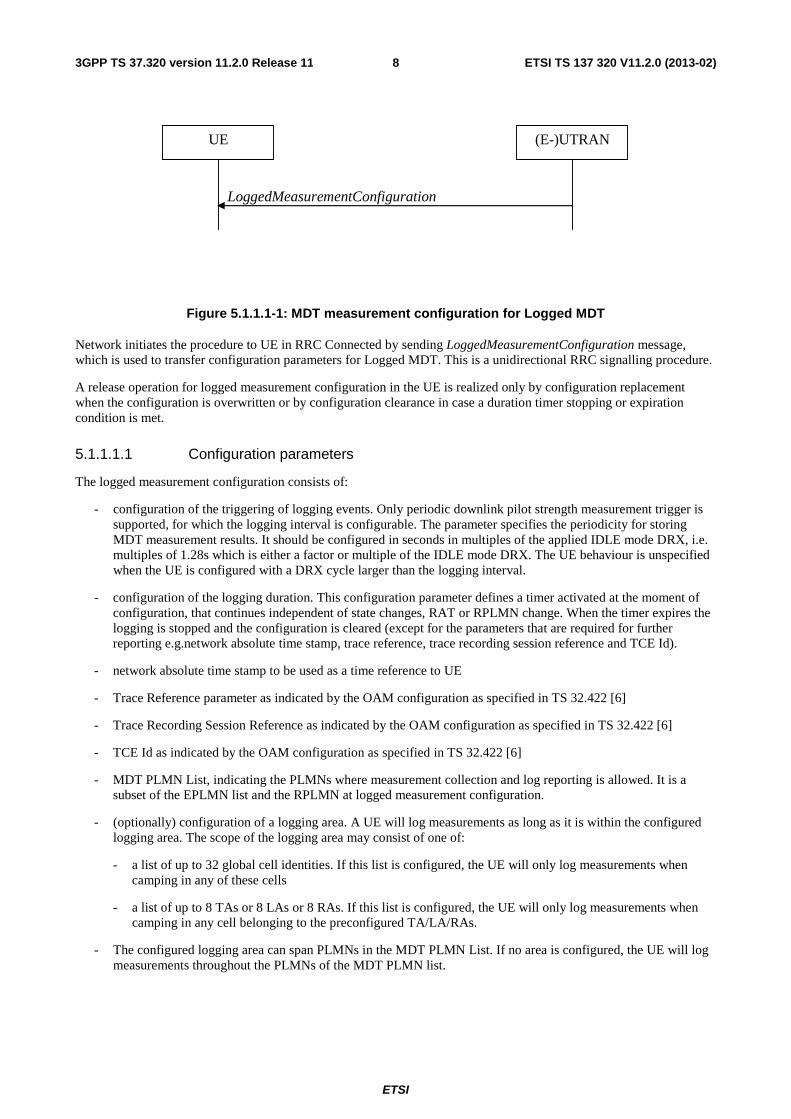
Figure 5.1.1.1-1: MDT measurement configuration for Logged MDT
Network initiates the procedure to UE in RRC Connected by sending LoggedMeasurementConfiguration message, which is used to transfer configuration parameters for Logged MDT. This is a unidirectional RRC signalling procedure.
A release operation for logged measurement configuration in the UE is realized only by configuration replacement when the configuration is overwritten or by configuration clearance in case a duration timer stopping or expiration condition is met.
5.1.1.1.1 Configuration parameters
The logged measurement configuration consists of:
- configuration of the triggering of logging events. Only periodic downlink pilot strength measurement trigger is supported, for which the logging interval is configurable. The parameter specifies the periodicity for storing MDT measurement results. It should be configured in seconds in multiples of the applied IDLE mode DRX, i.e. multiples of 1.28s which is either a factor or multiple of the IDLE mode DRX. The UE behaviour is unspecified when the UE is configured with a DRX cycle larger than the logging interval.
- configuration of the logging duration. This configuration parameter defines a timer activated at the moment of configuration, that continues independent of state changes, RAT or RPLMN change. When the timer expires the logging is stopped and the configuration is cleared (except for the parameters that are required for further reporting e.g.network absolute time stamp, trace reference, trace recording session reference and TCE Id).
- network absolute time stamp to be used as a time reference to UE
- Trace Reference parameter as indicated by the OAM configuration as specified in TS 32.422 [6]
- Trace Recording Session Reference as indicated by the OAM configuration as specified in TS 32.422 [6]
- TCE Id as indicated by the OAM configuration as specified in TS 32.422 [6]
- MDT PLMN List, indicating the PLMNs where measurement collection and log reporting is allowed. It is a subset of the EPLMN list and the RPLMN at logged measurement configuration.
- (optionally) configuration of a logging area. A UE will log measurements as long as it is within the configured logging area. The scope of the logging area may consist of one of:
- a list of up to 32 global cell identities. If this list is configured, the UE will only log measurements when camping in any of these cells
- a list of up to 8 TAs or 8 LAs or 8 RAs. If this list is configured, the UE will only log measurements when camping in any cell belonging to the preconfigured TA/LA/RAs.
- The configured logging area can span PLMNs in the MDT PLMN List. If no area is configured, the UE will log measurements throughout the PLMNs of the MDT PLMN list.
ETSI
ETSI TS 137 320 V11.2.0 (2013-02)93GPP TS 37.320 version 11.2.0 Release 11
5.1.1.1.2 Configuration effectiveness
The logged measurement configuration is provided in a cell by dedicated control while UE is in CONNECTED and implies:
- logged measurement configuration is active
- in IDLE UE state in E-UTRAN, or
- in IDLE mode, CELL_PCH and URA_PCH states in UTRAN
- until logging duration timer expires or stops
- logged measurement configuration and logs are maintained when the UE is in any state as described above, despite multiple periods interrupted by UE state transitions, i.e. when the UE is in CONNECTED state for E-UTRAN and CELL_DCH, CELL_FACH state in UTRAN
- logged measurement configuration and logs are maintained when the UE is in any state as described above in that RAT, despite multiple periods interrupted by UE presence in another RAT
There is only one RAT-specific logged measurement configuration for Logged MDT in the UE. When the network provides a configuration, any previously configured logged measurement configuration will be entirely replaced by the new one. Moreover, logged measurements corresponding to the previous configuration will be cleared at the same time. It is left up to the network to retrieve any relevant data before providing a new configuration.
NOTE: The network may have to do inter-RAT coordination.
When a logging area is configured, logged MDT measurements are performed as long as the UE is within this logging area. If no logging area is configured, logged MDT measurements are performed as long as the RPLMN is part of the MDT PLMN list. When the UE is not in the logging area or RPLMN is not part of the MDT PLMN list, the logging is suspended, i.e. the logged measurement configuration and the log are kept but measurement results are not logged.
NOTE: The logging duration timer continues.
In case the new PLMN that does not belong to the MDT PLMN list provides a logged measurement configuration any previously configured logged measurement configuration and corresponding log are cleared and overwritten without being retrieved.
5.1.1.2 Measurement collection
In "camp normally" state, a UE shall perform logging as per the logged measurement configuration. This state includes a period between cell selection criteria not being met and UE entering 'any cell selection' state, i.e. 10 s for E-UTRA (See TS 36.133 [3]) or 12 s for UTRA (See TS 25.133 [2]). In "any cell selection" or "camped on any cell" state, the periodic logging stops. However, it should be noted that the duration timer is kept running. When the UE re-enters 'camped normally' state and the duration timer has not expired, the periodic logging is restarted based on new DRX and logging resumes automatically (with a leap in time stamp).
The measurement quantity is fixed for Logged MDT (i.e. not configurable) and consists of both RSRP and RSRQ for EUTRA, both RSCP and Ec/No for UTRA, P-CCPCH RSCP for UTRA 1.28 TDD, Rxlev for GERAN, and Pilot Pn Phase and Pilot Strength for CDMA2000 if the serving cell is EUTRAN cell.
UE collects MDT measurements and continues logging according to the logged measurement configuration until UE memory reserved for MDT is full. In this case the UE stops logging, stops the log duration timer and starts the 48 hour timer.
5.1.1.3 Measurement reporting
5.1.1.3.1 Availability Indicator
A UE configured to perform Logged MDT measurements indicates the availability of Logged MDT measurements, by means of an indicator, in RRCConnectionSetupComplete message during connection establishment. Furthermore, the indicator (possibly updated) shall be provided within E-UTRAN handover and re-establishment, and UTRAN procedures involving the change of SRNC (SRNC relocation), CELL UPDATE, URA UPDATE messages as well as MEASUREMENT REPORT message in case of state transition to CELL_FACH without CELL UPDATE. The UE
ETSI
ETSI TS 137 320 V11.2.0 (2013-02)103GPP TS 37.320 version 11.2.0 Release 11
includes the indication in one of these messages at every transition to RRC Connected mode even though the logging period has not ended, upon connection to RAT which configured the UE to perform Logged MDT measurements and RPLMN which is equal to a PLMN in the MDT PLMN list. The indicator shall be also provided in UEInformationResponse message during MDT report retrieval in case the UE has not transferred the total log in one RRC message in order to indicate the remaining data availability. The UE will not indicate the availability of MDT measurements in another RAT or in a PLMN that is not in the MDT PLMN list. The network may decide to retrieve the logged measurements based on this indication. In case Logged MDT measurements are retrieved before the completion of the pre-defined logging duration, the reported measurement results are deleted, but MDT measurement logging will continue according to ongoing logged measurement configuration. In case the network does not retrieve Logged MDT measurements, UE should store non-retrieved measurements for 48 hours from the moment the duration timer for logging expired. There is no requirement to store non-retrieved data beyond 48 hours. In addition, all logged measurement configuration and the log shall be removed by the UE at switch off or detach.
5.1.1.3.2 Report retrieval
For Logged MDT the measurement reporting is triggered by an on-demand mechanism, i.e. the UE is asked by the network to send the collected measurement logs via RRC signalling. UE Information procedure defined in TS 25.331 [4] and TS 36.331 [5] is used to request UE to send the collected measurement logs. The reporting may occur in different cells than which the logged measurement configuration is signalled.
Transport of Logged MDT reports in multiple RRC messages is supported. With every request, the network may receive a part of the total UE log. To indicate the reported data is a segment, the UE shall include data availability indicator as specified in 5.1.1.3.1. In multiple RRC transmissions for segmented Logged MDT reporting, FIFO order is followed, i.e. the UE should provide oldest available measurement entries in earliest message. There is no requirement specified on the size of particular reporting parts. However, each reported part should be 'self-decodable', i.e. interpretable even in case all the other parts are not available.
The UE shall send an empty report when retrieval is attempted and the RPLMN is not in the MDT PLMN list.
5.1.1.3.3 Reporting parameters
The logged measurement report consists of measurement results for the serving cell (the measurement quantity), available UE measurements performed in idle for intra-frequency/inter-frequency/inter-RAT, time stamp and location information.
The number of neighbouring cells to be logged is limited by a fixed upper limit per frequency for each category below. The UE should log the measurement results for the neighbouring cells, if available, up to:
- 6 for intra-frequency neighbouring cells
- 3 for inter-frequency neighbouring cells
- 3 for GERAN neighbouring cells
- 3 for UTRAN (if non-serving) neighbouring cells
- 3 for E-UTRAN (if non-serving) neighbouring cells
- 3 for CDMA2000 (if serving is E-UTRA) neighbouring cells
The measurement reports for neighbour cells consist of:
- Physical cell identity of the logged cell
- Carrier frequency
- RSRP and RSRQ for EUTRA
- RSCP and Ec/No for UTRA,
- P-CCPCH RSCP for UTRA 1.28 TDD, and
ETSI
ETSI TS 137 320 V11.2.0 (2013-02)113GPP TS 37.320 version 11.2.0 Release 11
- Rxlev for GERAN
- Pilot Pn Phase and Pilot Strength for CDMA2000
For any logged cell (serving or neighbour), latest available measurement result made for cell reselection purposes is included in the log only if it has not already been reported. Measurements are performed in accordance with requirements defined in TS 25.133 [2] and TS 36.133 [3].
While logging neighbour cells measurements, the UE shall determine a fixed number of best cells based on the measurement quantity used for ranking during cell reselection per frequency or RAT.
The measurement report is self contained, i.e. the RAN node is able to interpret the Logged MDT reporting results even if it does not have access to the logged measurement configuration. Each measurement report also contains the necessary parameters for the network to be able to route the reports to the correct TCE and for OAM to identify what is reported. The parameters are sent to the UE in the logged configuration message, see subclause 5.1.1.1.1.
For each MDT measurement the UE includes a relative time stamp. The base unit for time information in the Logged MDT reports is the second. In the log, the time stamp indicates the point in time when periodic logging timer expires. The time stamp is counted in seconds from the moment the logged measurement configuration is received at the UE, relative to the absolute time stamp received within the configuration. The absolute time stamp is the current network time at the point when Logged MDT is configured to the UE. The UE echoes back this absolute reference time. The time format for Logged MDT report is: YY-MM-DD HH:MM:SS.
Location information is based on available location information in the UE. Thus, the Logged MDT measurements are tagged by the UE with location data in the following manner:
- ECGI or Cell-Id of the serving cell when the measurement was taken is always included in E-UTRAN or UTRAN respectively
- Detailed location information (e.g. GNSS location information) is included if available in the UE when the measurement was taken. If detailed location information is available the reporting shall consist of latitude and longitude. Depending on availability, altitude, uncertainty and confidence may be also additionally included. UE tags available detailed location information only once with upcoming measurement sample, and then the detailed location information is discarded, i.e. the validity of detailed location information is implicitly assumed to be one logging interval.
NOTE: The neighbour cell measurement information that is provided by the UE may be used to determine the UE location (RF fingerprint).
Depending on location information, measurement log/report consists of:
- time information, RF measurements, RF fingerprints, or
- time information, RF measurements, detailed location information (e.g. GNSS location information)
5.1.1.4 MDT context handling during handover
For Logged MDT in IDLE, CELL_PCH and URA_PCH, no need is identified to transfer an MDT context (any related configuration information about measurement and reporting) between (e)NBs/RNCs. In addition, MDT context is assumed to be released in the RAN nodes when the UE is in IDLE.
5.1.2 Immediate MDT procedures
5.1.2.1 Measurement configuration
For Immediate MDT, RAN measurements and UE measurements can be configured. The configuration for UE measurements is based on the existing RRC measurement procedures for configuration and reporting with some extensions for location information.
NOTE: No extensions related to time stamp are expected for Immediate MDT i.e. time stamp is expected to be provided by eNB/RNC.
ETSI
ETSI TS 137 320 V11.2.0 (2013-02)123GPP TS 37.320 version 11.2.0 Release 11
If area scope is included in the MDT configuration provided to the RAN, the UE is configured with respective measurement when the UE is connected to a cell that is part of the configured area scope.
5.1.2.2 Measurement reporting
For Immediate MDT, the UE provides detailed location information (e.g. GNSS location information) if available. The UE also provides available neighbour cell measurement information that may be used to determine the UE location (RF fingerprint). ECGI or Cell-Id of the serving cell when the measurement was taken is always assumed known in E-UTRAN or UTRAN respectively.
The location information which comes with UE radio measurements for MDT can be correlated with other MDT measurements, e.g. RAN measurements. For MDT measurements where UE location information is provided separately, it is assumed that the correlation of location information and MDT measurements should be done in the TCE based on time-stamps.
5.1.2.3 MDT context handling during handover
The measurements configured in the UE for Immediate MDT should fully comply with the transferring and reconfiguration principles for the current measurements configured in the UE for RRM purpose during handover (including conformance with Rel-8 and Rel-9).
The target node releases the measurements configured in the UE for immediate MDT which are no longer needed based on any MDT trace configuration it receives or does not receive.
In addition, MDT configuration handling during handover depends on MDT initiation from OAM defined in section 5.1.3:
- The MDT configuration configured by management based trace function will not propagate during handover.
- For LTE, the MDT configuration received by signalling based trace messages for a specific UE will propagate during intra-PLMN handover, and may propagate during inter-PLMN handover if the target PLMN is included in the Signalling based MDT PLMN List. This behaviour applies also for MDT configuration that includes area scope, regardless of whether the source or target cell is part of the configured area scope.
- For UMTS, the MDT configuration received by signalling based trace messages for a specific UE will continue during intra-PLMN handover, and may continue during inter-PLMN handover if the target PLMN is included in the Signalling based MDT PLMN List, except for the case of SRNS relocation.
Note: In the case of SRNS relocation, MDT may be reactivated by the Core Network following a successful relocation.
5.1.3 MDT Initiation
There are two cases that RAN should initiate a MDT measurements collection task. One is that the MDT task is initiated without targeting a specific UE by the cell traffic trace, i.e. management based trace function from OAM. The other is that the MDT task is initiated towards a specific UE by the signaling trace activation messages from CN nodes, i.e. the Initial Context Setup message, the Trace Start message or the Handover request message in E-UTRAN, the CN Invoke Trace message in UTRAN. The detailed procedures to transfer the MDT configurations to RAN are specified in TS 32.422 [6].
For signalling based MDT, the CN shall not initiate MDT towards a particular user unless it is allowed. If the Signalling Based MDT PLMN List is not available, the RAN behaves as early release (Rel-10). For management based MDT, the CN indicates to the RAN whether MDT is allowed to be configured by the RAN for this user considering e.g. user consent and roaming status (see TS 32.422 [6]), by providing user consent and optionally the Management Based MDT PLMN List. If the Management Based MDT PLMN List is not available, the RAN behaves as early release (Rel-10). A UE is configured with an MDT PLMN List only if user consent is valid for the RPLMN.
5.1.4 UE capabilities
MDT relevant UE capabilities are component of radio access UE capabilities. Thus the procedures used for handling UE radio capabilities over (E-)UTRAN apply.

ETSI
ETSI TS 137 320 V11.2.0 (2013-02)133GPP TS 37.320 version 11.2.0 Release 11
The UE indicates one capability bit for MDT support, which indicates support for Logged MDT. The UE may also indicate capability for stand-alone GNSS positioning.
The LTE UE may indicate a capability for RX-TX time difference measurement for E-Cell ID positioning for MDT.
5.1.5 Void
5.1.6 Accessibility measurements
The UE logs failed RRC connection establishments for LTE and UMTS, i.e. a log is created when the RRC connection establishment procedure fails. The UE logs failed RRC connection establishments without the need for prior configuration by the network.
The UE stores the Selected PLMN on the RRC connection establishment failure. Only if that PLMN is the same as the RPLMN, the UE may report the log.
Note: There is no expected performance degradation for networks using EPLMNs.
The trigger for creating a log related to a failed RRC connection establishment is for LTE when timer T300 expires and for UMTS when V300 is greater then N300.
The UE shall store the following information related to the failed RRC connection establishment:
- Time stamp, which is the elapsed time between logging and reporting the log.
- The global cell identity of the serving cell when the RRC connection establishment fails, i.e. the cell which the UE attempted to access.
- The latest available radio measurements for any frequency or RAT
- The latest detailed location information, if available.
- For LTE:
- Number of Random Access Preambles transmitted,
- Indication whether the maximum transmission power was used.
- Contention detected
- For UMTS FDD:
- Number of RRC Connection Request attempts (e.g. T300 expiry after receiving ACK and AICH)
- For UMTS TDD:
- Number of RRC Connection Request attempts.
- Whether the FPACH is received or whether the maximum number Mmax of synchronisation attempts is reached.
- Failure indication of the E-RUCCH transmission. It is only applied for common E-DCH is supported by UE and network.
5.2 E-UTRAN solutions
5.2.1 RRC_CONNECTED
UE in RRC Connected does not support Logged MDT in this release of the specification. In order to support Immediate MDT where MDT measurements are executed in the UE, the existing RRC measurement configuration and reporting procedures apply. Some extensions are used to carry location information.
ETSI
ETSI TS 137 320 V11.2.0 (2013-02)143GPP TS 37.320 version 11.2.0 Release 11
5.2.1.1 Measurements and reporting triggers for Immediate MDT
Measurements to be performed for Immediate MDT purposes involve reporting triggers and criteria utilized for RRM. In addition, there are measurements performed in eNB. In particular, the following measurements shall be supported for Immediate MDT performance:
Measurements:
- M1: RSRP and RSRQ measurement by UE, see TS 36.214 [9].
- M2: Power Headroom measurement by UE, see TS 36.213 [11].
- M3: Received Interference Power measurement by eNB, see TS 36.214 [9]. This is a cell measurement. One sample is logged each measurement collection period, where one sample corresponds to a measurement period as specified in TS 36.133 [3].
- M4: Data Volume measurement separately for DL and UL, per QCI per UE, by eNB, see TS 36.314 [13].
- M5: Scheduled IP Throughput for MDT measurement separately for DL and UL, per RAB per UE and per UE for the DL, per UE for the UL, by eNB, see TS 36.314 [13]. QCI values of the RABs that have contributed to a measurement value are logged with the measurement values.
UE reporting triggers, configured for MDT:
- For M1:
- Periodic
- Serving cell becomes worse than threshold; event A2
- Event triggered periodic; event A2
Measurement collection triggers in the eNB:
- For M1:
- Reception of event-triggered measurement reports according to existing RRM configuration for events A1, A2, A3, A4, A5 A6, B1 or B2
- For M2:
- Reception of Power Headroom Report (PHR) according to existing RRM configuration.
NOTE: PHR is carried by MAC signalling. Thus, the existing mechanism of PHR transmission applies, see TS 36.321 [10].
- For M3:
- End of measurement collection period
- For M4:
- End of measurement collection period.
- For M5:
- End of measurement collection period.
5.2.1.2 Enhancement to Radio Link Failure report
The Radio Link Failure report contains information related to the latest connection failure experienced by the UE. The connection failure can be Radio Link Failure (RLF) or Handover Failure (HOF). The contents of the RLF report and the procedure for retrieving it by an eNB are described in TS 36.300 [12].
RLF reports can be collected by OAM. Upon RLF/HOF detection in the UE, rlfReport defined in TS 36.331 [5] also includes available location information on where RLF occurred, i.e. if detailed location information (e.g. GNSS location information) is available the reported location information in rlfReport consists of:

ETSI
ETSI TS 137 320 V11.2.0 (2013-02)153GPP TS 37.320 version 11.2.0 Release 11
- Latitude, longitude (mandatory)
- Altitude (conditional on availability)
- Velocity (conditional on availability)
- Direction (conditional on availability).
5.2.1.3 Detailed Location Information
The M1 measurements are tagged by the UE with location data in the following manner:
- Detailed location information (e.g. GNSS location information) is included if available in the UE when the measurement was taken. If detailed location information is available the reporting shall consist of latitude and longitude. Depending on availability, altitude , uncertainty and confidence may be also additionally included. The UE should include the available detailed location information only once. If the detailed location information is obtained by GNSS positioning method, GNSS time information shall be included. For both event based and periodic reporting (see 5.2.1.1), the detailed location information is included if the report is transmitted within the validity time after the detailed location information was obtained. The validity evaluation of detailed location information is left to UE implementation.
For immediate MDT, the eNB can request the UE to attempt to make GNSS location information available. Standalone GNSS is used as the default baseline. It is desired that the UE provides fresh location information with each immediate MDT measurement report. The details how this is achieved is up to UE implementation.
The eNB may use an Enhanced Cell ID mechanism for location. The eNB can forward the raw E-Cell ID specific measurements to the TCE or to compute the location information in the eNB and to forward that information to the TCE. When E-Cell ID positioning is requested, the eNB may choose to not use E-Cell ID positioning for collected measurement for which the UE provides detailed location information.
5.2.2 RRC_IDLE
For UE in RRC_IDLE state Logged MDT procedures as described in 5.1.1 apply.
Logged MDT measurements are sent on Signalling Radio Bearer SRB2 in RRC_CONNECTED state.
5.3 UTRAN solutions
5.3.1 UTRA RRC Connected
In CELL_PCH and URA_PCH states UE supports Logged MDT as described in 5.1.1. In CELL_DCH state UE supports Immediate MDT as described in 5.1.2. In CELL_FACH state MDT is not supported in the current release.
5.3.1.1 Measurements and reporting events for Immediate MDT
The solutions for Immediate MDT in UTRAN are only applicable for UEs in CELL_DCH state. Measurements to be performed for Immediate MDT purposes involve normal UTRAN reporting triggers and criteria utilized for controlling the RRC connection. In addition, there are measurements defined that are performed in UTRAN. In particular, the following measurements shall be supported for Immediate MDT:
Measurements:
- M1: CPICH RSCP and CPICH Ec/No measurement by UE, see TS 25.215 [7], TS 25.225 [8].
- M2: P-CCPCH RSCP and Timeslot ISCP for UTRA 1.28 TDD, see TS 25.225 [8].
- M3: SIR and SIR error (FDD) by NodeB, see TS 25.215 [7] and TS 25.225 [8].
- M4: UE power headroom (UPH) by the UE, applicable for E-DCH transport channels, see TS 25.215 [7] and TS 25.225 [8].
ETSI
ETSI TS 137 320 V11.2.0 (2013-02)163GPP TS 37.320 version 11.2.0 Release 11
- M5: Received total wideband power (RTWP) by Node B, see TS 25.215 [7] TS 25.225 [8], and TS 25.133 [2]. This is a cell measurement.
- M6: Data Volume measurement, separately for DL and UL, per QoS class per UE, by RNC.
- M7: Throughput measurement, separately for DL and UL, per RAB per UE and per UE, by RNC. Traffic class and Traffic Handling Priority for interactive RABs for the RABs that have contributed to a measurement value are logged with the measurement values.
UE reporting triggers, configured for MDT:
- For M1:
- Periodic
- Primary CPICH becomes worse than an absolute threshold; event 1F
- For M2:
- Periodic
- Timeslot ISCP above a certain threshold (TDD); event 1I
Measurement collection triggers in the RAN:
- For M1 and M2:
- Reception of event triggered measurement reports according to existing RRM configuration, for measurement types intra-frequency measurement, inter-frequency measurement and inter-RAT measurement.
- For M3:
- When available
- For M4:
- Reception of UPH according to existing RRM configuration
- Provided by the UE according to RRM configuration.
- UPH samples may be collected and logged:
- always
- periodic, one sample per period.
- periodic, one sample per period, when measurement value < threshold.
- For M5:
- When available.
- End of measurement collection period.
- For M6:
- End of measurement collection period.
- For M7:
- End of measurement collection period.
5.3.1.2 Detailed Location Information
For Immediate MDT, existing procedures for UE Location information are used to obtain detailed location information.
ETSI
ETSI TS 137 320 V11.2.0 (2013-02)173GPP TS 37.320 version 11.2.0 Release 11
5.3.2 UTRA Idle
For UEs in UTRA Idle mode Logged MDT procedures as described in 5.1.1 apply.
Logged MDT measurements are sent on Signalling Radio Bearer SRB4 in RRC Connected mode.
ETSI
ETSI TS 137 320 V11.2.0 (2013-02)183GPP TS 37.320 version 11.2.0 Release 11
Annex A (informative): Coverage use cases The MDT data reported from UEs and the RAN may be used to monitor and detect coverage problems in the network. Some examples of use cases of coverage problem monitoring and detection are described in the following:
- Coverage hole: A coverage hole is an area where the signal level SNR (or SINR) of both serving and allowed neighbor cells is below the level needed to maintain basic service (SRB & DL common channels), i.e. coverage of PDCCH. Coverage holes are usually caused by physical obstructions such as new buildings, hills, or by unsuitable antenna parameters, or just inadequate RF planning. UE in coverage hole will suffer from call drop and radio link failure. Multi-band and/or Multi-RAT UEs may go to other network layer instead.
- Weak coverage: Weak coverage occurs when the signal level SNR (or SINR) of serving cell is below the level needed to maintain a planned performance requirement (e.g. cell edge bit-rate).
- Pilot Pollution: In areas where coverage of different cells overlap a lot, interference levels are high, power levels are high, energy consumption is high and cell performance may be low. This problem phenomenon has been called 'pilot pollution', and the problem can be addressed by reducing coverage of cells. Typically in this situation UEs may experience high SNR to more than one cell and high interference levels.
- Overshoot coverage: Overshoot occurs when coverage of a cell reaches far beyond what is planned. It can occur as an 'island' of coverage in the interior of another cell, which may not be a direct neighbor. Reasons for overshoot may be reflections in buildings or across open water, lakes etc. UEs in this area may suffer call drops or high interference. Possible actions to improve the situation include changing the coverage of certain cells and mobility blacklisting of certain cells.
- Coverage mapping: There should be knowledge about the signal levels in the cell areas in order to get a complete view for the coverage and be able to assess the signal levels that can be provided in the network. This means that there should be measurements collected in all parts of the network, and not just in the areas where there are potential coverage issues.
- UL coverage: Poor UL coverage might impact user experience in terms of call setup failure / call drop / poor UL voice quality. Therefore, coverage should be balanced between uplink and downlink connections. Possible UL coverage optimization comprises adapting the cellular coverage by changing the site configuration (antennas) but also about adjusting the UL related parameters in the way that they allow optimized usage of UL powers in different environments.
- Cell boundary mapping: There should be knowledge about the location of (intra/inter RAT) cell boundaries in order to compare to the expected/planned network setting. Poor handover performance may be caused by changed cell boundaries due to changes in the physical condition of the surrounding area, e.g., construction of new buildings, bridge or tunnel near the handover area.
- Coverage mapping for pico cell in CA scenario: As a realization of CA scenario 4 in TS 36.300 [12], pico cell may be deployed in area where high traffic occurs. The location where a pico cell is available to be added as an SCell may show whether the deployment of pico cell is according to the needs of capacity increase.
ETSI
ETSI TS 137 320 V11.2.0 (2013-02)193GPP TS 37.320 version 11.2.0 Release 11
Annex B (informative): QoS verification use cases The MDT data reported from UEs and the RAN may be used to verify Quality of Service, assess user experience from RAN perspective, and to assist network capacity extension. Use cases are described in the following:
- Traffic Location: MDT functionality to obtain information of where data traffic is transferred within a cell.
- User QoS Experience: MDT functionality to assess the QoS experience for a specific UE together with location information.
ETSI
ETSI TS 137 320 V11.2.0 (2013-02)203GPP TS 37.320 version 11.2.0 Release 11
Annex C (informative): Measurements This annex provides information on measurements that are used for MDT and are not specified elsewhere.
Throughput measurement for UMTS. The throughput is measured on PDCP or RLC level. A measurement value for a UE and each RAB of the UE is provided each measurement period, except if the value is zero. The measurement is performed separately for UL and DL, and is performed for PS RABs. Idle periods shall not be taken into account, when there is no data buffered or no data being transmitted.
Data Volume measurement for UMTS. Data Volume is measured on PDCP or RLC (without Layer 2 overhead). A measurement value for a QoS class for a UE is provided each measurement period, except if the value is zero, where the QoS class is one of conversational, interactive, streaming or background. The measurement is performed separately for UL and DL, and is performed for PS RABs.
ETSI
ETSI TS 137 320 V11.2.0 (2013-02)213GPP TS 37.320 version 11.2.0 Release 11
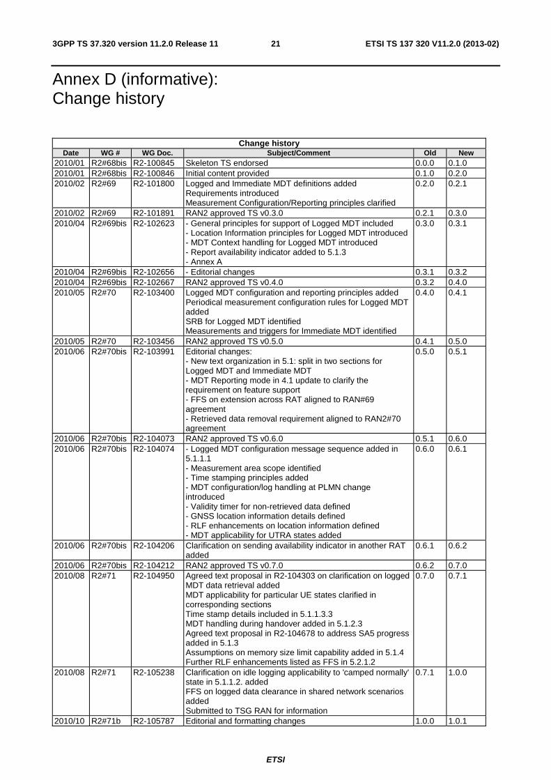
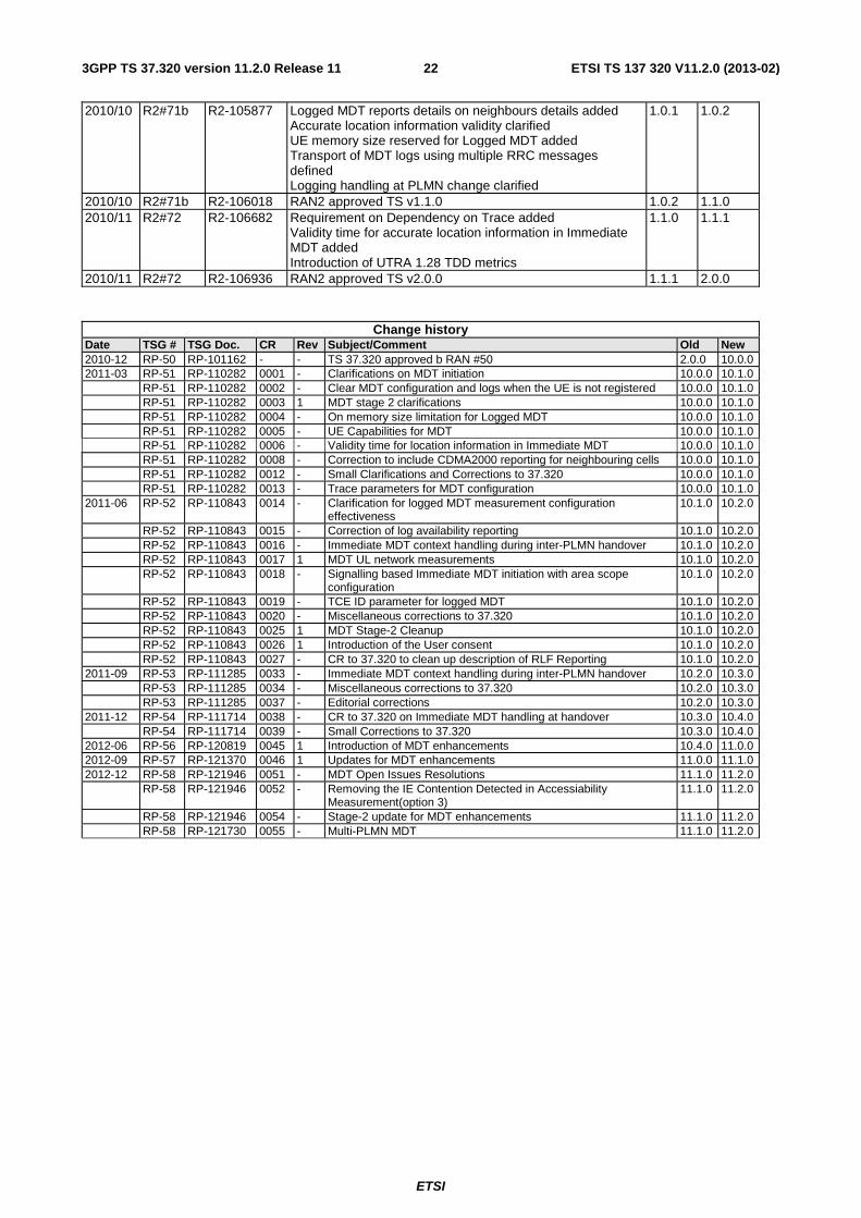
Annex D (informative): Change history
Change history Date WG # WG Doc. Subject/Comment Old New
2010/01 R2#68bis R2-100845 Skeleton TS endorsed 0.0.0 0.1.0 2010/01 R2#68bis R2-100846 Initial content provided 0.1.0 0.2.0 2010/02 R2#69 R2-101800 Logged and Immediate MDT definitions added
Requirements introduced Measurement Configuration/Reporting principles clarified
0.2.0 0.2.1
2010/02 R2#69 R2-101891 RAN2 approved TS v0.3.0 0.2.1 0.3.0 2010/04 R2#69bis R2-102623 - General principles for support of Logged MDT included
- Location Information principles for Logged MDT introduced - MDT Context handling for Logged MDT introduced - Report availability indicator added to 5.1.3 - Annex A
0.3.0 0.3.1
2010/04 R2#69bis R2-102656 - Editorial changes 0.3.1 0.3.2 2010/04 R2#69bis R2-102667 RAN2 approved TS v0.4.0 0.3.2 0.4.0 2010/05 R2#70 R2-103400 Logged MDT configuration and reporting principles added
Periodical measurement configuration rules for Logged MDT added SRB for Logged MDT identified Measurements and triggers for Immediate MDT identified
0.4.0 0.4.1
2010/05 R2#70 R2-103456 RAN2 approved TS v0.5.0 0.4.1 0.5.0 2010/06 R2#70bis R2-103991 Editorial changes:
- New text organization in 5.1: split in two sections for Logged MDT and Immediate MDT - MDT Reporting mode in 4.1 update to clarify the requirement on feature support - FFS on extension across RAT aligned to RAN#69 agreement - Retrieved data removal requirement aligned to RAN2#70 agreement
0.5.0 0.5.1
2010/06 R2#70bis R2-104073 RAN2 approved TS v0.6.0 0.5.1 0.6.0 2010/06 R2#70bis R2-104074 - Logged MDT configuration message sequence added in
5.1.1.1 - Measurement area scope identified - Time stamping principles added - MDT configuration/log handling at PLMN change introduced - Validity timer for non-retrieved data defined - GNSS location information details defined - RLF enhancements on location information defined - MDT applicability for UTRA states added
0.6.0 0.6.1
2010/06 R2#70bis R2-104206 Clarification on sending availability indicator in another RAT added
0.6.1 0.6.2
2010/06 R2#70bis R2-104212 RAN2 approved TS v0.7.0 0.6.2 0.7.0 2010/08 R2#71 R2-104950 Agreed text proposal in R2-104303 on clarification on logged
MDT data retrieval added MDT applicability for particular UE states clarified in corresponding sections Time stamp details included in 5.1.1.3.3 MDT handling during handover added in 5.1.2.3 Agreed text proposal in R2-104678 to address SA5 progress added in 5.1.3 Assumptions on memory size limit capability added in 5.1.4 Further RLF enhancements listed as FFS in 5.2.1.2
0.7.0 0.7.1
2010/08 R2#71 R2-105238 Clarification on idle logging applicability to 'camped normally' state in 5.1.1.2. added FFS on logged data clearance in shared network scenarios added Submitted to TSG RAN for information
0.7.1 1.0.0
2010/10 R2#71b R2-105787 Editorial and formatting changes 1.0.0 1.0.1
ETSI
ETSI TS 137 320 V11.2.0 (2013-02)223GPP TS 37.320 version 11.2.0 Release 11
2010/10 R2#71b R2-105877 Logged MDT reports details on neighbours details added Accurate location information validity clarified UE memory size reserved for Logged MDT added Transport of MDT logs using multiple RRC messages defined Logging handling at PLMN change clarified
1.0.1 1.0.2
2010/10 R2#71b R2-106018 RAN2 approved TS v1.1.0 1.0.2 1.1.0 2010/11 R2#72 R2-106682 Requirement on Dependency on Trace added
Validity time for accurate location information in Immediate MDT added Introduction of UTRA 1.28 TDD metrics
1.1.0 1.1.1
2010/11 R2#72 R2-106936 RAN2 approved TS v2.0.0 1.1.1 2.0.0
Change history Date TSG # TSG Doc. CR Rev Subject/Comment Old New 2010-12 RP-50 RP-101162 - - TS 37.320 approved b RAN #50 2.0.0 10.0.0 2011-03 RP-51 RP-110282 0001 - Clarifications on MDT initiation 10.0.0 10.1.0 RP-51 RP-110282 0002 - Clear MDT configuration and logs when the UE is not registered 10.0.0 10.1.0 RP-51 RP-110282 0003 1 MDT stage 2 clarifications 10.0.0 10.1.0 RP-51 RP-110282 0004 - On memory size limitation for Logged MDT 10.0.0 10.1.0 RP-51 RP-110282 0005 - UE Capabilities for MDT 10.0.0 10.1.0 RP-51 RP-110282 0006 - Validity time for location information in Immediate MDT 10.0.0 10.1.0 RP-51 RP-110282 0008 - Correction to include CDMA2000 reporting for neighbouring cells 10.0.0 10.1.0 RP-51 RP-110282 0012 - Small Clarifications and Corrections to 37.320 10.0.0 10.1.0 RP-51 RP-110282 0013 - Trace parameters for MDT configuration 10.0.0 10.1.0 2011-06 RP-52 RP-110843 0014 - Clarification for logged MDT measurement configuration
effectiveness 10.1.0 10.2.0
RP-52 RP-110843 0015 - Correction of log availability reporting 10.1.0 10.2.0 RP-52 RP-110843 0016 - Immediate MDT context handling during inter-PLMN handover 10.1.0 10.2.0 RP-52 RP-110843 0017 1 MDT UL network measurements 10.1.0 10.2.0 RP-52 RP-110843 0018 - Signalling based Immediate MDT initiation with area scope
configuration 10.1.0 10.2.0
RP-52 RP-110843 0019 - TCE ID parameter for logged MDT 10.1.0 10.2.0 RP-52 RP-110843 0020 - Miscellaneous corrections to 37.320 10.1.0 10.2.0 RP-52 RP-110843 0025 1 MDT Stage-2 Cleanup 10.1.0 10.2.0 RP-52 RP-110843 0026 1 Introduction of the User consent 10.1.0 10.2.0 RP-52 RP-110843 0027 - CR to 37.320 to clean up description of RLF Reporting 10.1.0 10.2.0 2011-09 RP-53 RP-111285 0033 - Immediate MDT context handling during inter-PLMN handover 10.2.0 10.3.0 RP-53 RP-111285 0034 - Miscellaneous corrections to 37.320 10.2.0 10.3.0 RP-53 RP-111285 0037 - Editorial corrections 10.2.0 10.3.0 2011-12 RP-54 RP-111714 0038 - CR to 37.320 on Immediate MDT handling at handover 10.3.0 10.4.0 RP-54 RP-111714 0039 - Small Corrections to 37.320 10.3.0 10.4.0 2012-06 RP-56 RP-120819 0045 1 Introduction of MDT enhancements 10.4.0 11.0.0 2012-09 RP-57 RP-121370 0046 1 Updates for MDT enhancements 11.0.0 11.1.0 2012-12 RP-58 RP-121946 0051 - MDT Open Issues Resolutions 11.1.0 11.2.0 RP-58 RP-121946 0052 - Removing the IE Contention Detected in Accessiability
Measurement(option 3) 11.1.0 11.2.0
RP-58 RP-121946 0054 - Stage-2 update for MDT enhancements 11.1.0 11.2.0 RP-58 RP-121730 0055 - Multi-PLMN MDT 11.1.0 11.2.0

ETSI
ETSI TS 137 320 V11.2.0 (2013-02)233GPP TS 37.320 version 11.2.0 Release 11
History
Document history
V11.1.0 November 2012 Publication
V11.2.0 February 2013 Publication