TRW Pintle Engine Heritage and Performance...
23
AIAA 2000-3871 Page 1 of 22 TRW Pintle Engine Heritage and Performance Characteristics Gordon A. Dressler* and J. Martin Bauer** TRW Inc., Redondo Beach, CA 90278 Abstract The pintle injector rocket engine is fundamentally different from other rocket engines, which nearly universally employ a series of separate propellant injection orifices distributed across the diameter of the headend of the combustion chamber. The pintle’s central, singular injection geometry results in a combustion chamber flowfield that varies greatly from that of conventional rocket engines. These differences result in certain operational characteristics of great benefit to rocket engine design, performance, stability, and test flexibility. The mid-1950’s origin of the pintle injector concept and the subsequent early development work and applications in rocket engines are reviewed. The pintle engine’s key design and operational features are compared to conventional rocket engines. Pintle injector design refinements and associated recent applications are discussed. The presentation includes photographs and summaries of many different rocket engines that TRW has developed and successfully flown, each of which used the pintle injector. Introduction The pintle injector is distinguished by its unique geometry and injection characteristics compared to the impinging or coaxial distributed-element injectors typically used on liquid bipropellant rocket engines. The pintle injector design can deliver high combustion efficiency (typically 96–99%) and enables implementing some unique operating features, such as deep throttling and injector face shutoff. Its design simplicity makes it ideally suited for use on low cost engines. Significantly lower development and qualification costs are realized with pintle engines because their injectors can be easily adjusted and optimized by changing only two simple parts. The TRW pintle engine has a demonstrated heritage of being low cost, highly reliable and safe to operate. The origins of the pintle injector were early laboratory experimental apparatus, used by JPL in the mid-1950’s, to study propellant mixing and combustion reaction times of hypergolic liquid propellants. The pintle injector was reduced to practice and developed by TRW starting in 1960; however, it was not until 1972 that the pintle injector design patent was publicly released. Over the last 40 years, TRW has developed over 60 different pintle engine designs at least to the point of hot fire characterization testing. Bipropellant pintle engines have encompassed a wide range of thrust: 5 lbf on a Brilliant Pebbles thruster, 100 lbf on liquid apogee engines for spacecraft, 1,000–10,000 lbf on the Apollo lunar module descent engine, 250,000 lbf on a “Big Dumb Booster” engine, and 650,000 lbf on a development LOX/LH2 engine currently being readied for testing at NASA Stennis Space Center. Over 130 bipropellant engines using a pintle injector have flown successfully. Flight programs relying on TRW bipropellant engines have included Apollo LEMDE, Delta launch vehicle, MMBPS, ISPS, ANIK E-1/E-2 and Intelsat-K, ERIS KKV stage, FMTI, and NASA Chandra. There has never been a flight failure of a TRW bipropellant engine. Significantly, there has never been an instance of combustion instability in a pintle engine during any ground or flight operations, despite scaling over a range of 50,000:1 in thrust and 250:1 in chamber pressure and operation with 25 different propellant * Propulsion Systems Center Chief Engineer, Member of AIAA ** Senior Engineering Manager Copyright 2000 by TRW Inc. Published by American Institute of Aeronautics and Astronautics, Inc., with permission.
Transcript of TRW Pintle Engine Heritage and Performance...

AIAA 2000-3871Page 1 of 22
TRW Pintle Engine Heritage and Performance Characteristics
Gordon A. Dressler* and J. Martin Bauer**TRW Inc., Redondo Beach, CA 90278
AbstractThe pintle injector rocket engine is
fundamentally different from other rocketengines, which nearly universally employ aseries of separate propellant injection orificesdistributed across the diameter of the headendof the combustion chamber. The pintle’scentral, singular injection geometry results ina combustion chamber flowfield that variesgreatly from that of conventional rocketengines. These differences result in certainoperational characteristics of great benefit torocket engine design, performance, stability,and test flexibility.
The mid-1950’s origin of the pintleinjector concept and the subsequent earlydevelopment work and applications in rocketengines are reviewed. The pintle engine’s keydesign and operational features are comparedto conventional rocket engines. Pintle injectordesign refinements and associated recentapplications are discussed. The presentationincludes photographs and summaries of manydifferent rocket engines that TRW hasdeveloped and successfully flown, each ofwhich used the pintle injector.
IntroductionThe pintle injector is distinguished by its
unique geometry and injection characteristicscompared to the impinging or coaxialdistributed-element injectors typically used onliquid bipropellant rocket engines. The pintleinjector design can deliver high combustionefficiency (typically 96–99%) and enablesimplementing some unique operating features,such as deep throttling and injector faceshutoff. Its design simplicity makes it ideallysuited for use on low cost engines.Significantly lower development andqualification costs are realized with pintle
engines because their injectors can be easilyadjusted and optimized by changing only twosimple parts.
The TRW pintle engine has ademonstrated heritage of being low cost,highly reliable and safe to operate. Theorigins of the pintle injector were earlylaboratory experimental apparatus, used byJPL in the mid-1950’s, to study propellantmixing and combustion reaction times ofhypergolic liquid propellants. The pintleinjector was reduced to practice anddeveloped by TRW starting in 1960; however,it was not until 1972 that the pintle injectordesign patent was publicly released. Over thelast 40 years, TRW has developed over 60different pintle engine designs at least to thepoint of hot fire characterization testing.Bipropellant pintle engines have encompasseda wide range of thrust: 5 lbf on a BrilliantPebbles thruster, 100 lbf on liquid apogeeengines for spacecraft, 1,000–10,000 lbf onthe Apollo lunar module descent engine,250,000 lbf on a “Big Dumb Booster” engine,and 650,000 lbf on a development LOX/LH2engine currently being readied for testing atNASA Stennis Space Center. Over 130bipropellant engines using a pintle injectorhave flown successfully. Flight programsrelying on TRW bipropellant engines haveincluded Apollo LEMDE, Delta launchvehicle, MMBPS, ISPS, ANIK E-1/E-2 andIntelsat-K, ERIS KKV stage, FMTI, andNASA Chandra. There has never been a flightfailure of a TRW bipropellant engine.
Significantly, there has never been aninstance of combustion instability in a pintleengine during any ground or flight operations,despite scaling over a range of 50,000:1 inthrust and 250:1 in chamber pressure andoperation with 25 different propellant
* Propulsion Systems Center Chief Engineer, Member of AIAA** Senior Engineering Manager
Copyright 2000 by TRW Inc. Published by American Institute of Aeronautics and Astronautics, Inc., with permission.

AIAA 2000-3871Page 2 of 22
combinations. The pintle injector hasdemonstrated direct injection of near-normalboiling point LOX/LH2 propellants with highperformance and proven dynamic combustionstability. “Bomb” stability testing has beenperformed on six different pintle engines withfour different propellant combinations,including the physically large 250,000 lbfengine.
With its unique capabilities, the pintleinjector has been used in very demandingapplications, such as an 8,200 lbf engine thatcould throttle over a 19:1 thrust range andperform 8 millisecond pulses. Also, with itsready adaptability to shut off propellants at theinjector face, the pintle injector is ideallysuited to operation with gelled propellants andhas enabled the first successful flight of a gelpropellant tactical missile. Most recently, thepintle engine design has been investigated as ameans of easily reducing the cost of largeengines for launch vehicles by as much as75% beyond that achieved on recentprograms, such as EELV.
The history of development and flightapplications of the pintle engine over the lastforty years will be summarized. The featuresand performance characteristics of the TRWpintle injector and associated engine designswill be described. Features of the pintleinjector will be compared to those of otherinjectors commonly used in rocket engines.
Pintle Injector Design ConceptThe basic concept of the bipropellant
pintle injector is shown in Figure 1.One propellant (here shown as fuel) is fed
through outer injector flow passages into acircumferential annulus—formed between theinjector body "snout" and the central injectorelement—which meters the flow into thecombustion chamber. This propellant exitsthe injector as an axially flowing annular sheetthat arrives at the impingement point with acircumferentially uniform velocity profile.
The other propellant (here shown asoxidizer) enters the injector body via aseparate centrally-located passage and flowsaxially through a central pintle sleeve towardthe injector, where it is turned to uniformradial flow by the pintle tip's internalcontoured surface. This propellant is meteredinto the combustion chamber by passingthrough: (a) a continuous gap formed betweenthe cylindrical sleeve and pintle tip, or (b)slots or holes of certain geometry machinedinto the end of the sleeve which may beintegral with the tip, or (c) a combination ofthe above two designs. Thus, the pintleinjector can meter the central propellant as acontinuous radial sheet, a series of radiallyflowing “spokes”, or combination of both.Figure 2 shows the injection geometry of theslotted, or “toothed” pintle injector withattached tip.
Experience has shown that the pintleinjector can be designed to give highperformance with either fuel or oxidizer beingthe centrally-metered propellant. Generally,fuel is chosen as the central propellant inradiation-cooled engines because the radialinjection momentum can be designed topersist to the wall, thus enabling a convenient
Figure 1. Pintle Injector Concept (Continuous Gap,Fixed Thrust or Thottling Designs)

AIAA 2000-3871Page 3 of 22
means of “tuning” the injector to provide fuelfilm cooling of the combustion chamber.Ultimately, the decision to meter either fuel oroxidizer as the central propellant depends onmany design trade-offs. TRW has successfullyflown both ox-centered and fuel-centeredpintle engines.
The 90°, axial-radial impingement of thetwo propellant streams combined with thespecific geometry of the resulting atomizationand mixing "fan" is fundamental to the pintleinjector providing both high combustionefficiency and inherent combustion stability.
Figure 3 is a series of photographs ofwater flow tests on a single pintle injector,looking back toward the injector element andheadend dome. Figure 3(a) showscharacteristic flow for the outer, annularinjection; Figure 3(b) shows a wider-angleview of the inner passage flow being injectedas a radial sheet; and Figure 3(c) shows thespray fan resulting from the combinedinjected, but non-reacting, flows.
The single central injector sleeve, shownin Figure 1, is easily designed to be movable.This provides a convenient and reliable meansof throttling the injector to maintain nearlyconstant injection velocities across a widerange of injected propellant flowrates. TRWhas used this feature to great advantage, asdiscussed below, to produce deep (>10:1)throttling engines that maintain high
Figure 2. Pintle Injector Concept (Slotted Injection,Fixed Thrust Design)
(c) Combined Flows
(a) Outer Flow Only
(b) Inner Flow Only
Figure 3. Photographs of Injector Water Flows
AIAA 2000-3871Page 4 of 22
combustion efficiency and insensitivity tochug instability across their operating range.
Where injectors employ a movable sleeve,a separate on-axis support rod (or tube) andcruciform guide vanes are used to support thepintle tip independent of the sleeve. It is seenthat movement of the single sleeve cansimultaneously meter both the fuel and theoxidizer at their immediate points of injection.Furthermore, with proper design the sleevecan be made to fully shutoff both propellantsat the injector face (hence, “face shutoff”),thereby eliminating all dribble volume fromthe injector. In fact, TRW has implemented“face shutoff only” injectors where thismovable sleeve was the only “valving”locking off propellant supply pressures up toapproximately 3000 psia.
The distance from the outer propellant’sannular entrance point into the combustionchamber to the point of contact with theinjected central propellant stream is referred toas the injector's "skip distance". Thisparameter, together with others such as thepintle’s insertion depth into the chamber, it’sdiameter relative to the chamber diameter andinjection stream thicknesses, velocities andrelative momentums, must be considered inproper design of pintle injectors.
Careful design of the pintle injectorensures (a) good atomization and mixing ofthe two propellant streams for highcombustion efficiency, (b) proper fuel filmcooling at the chamber wall, and (c)evaporative cooling of the exposed headenddome for good thermal margin.
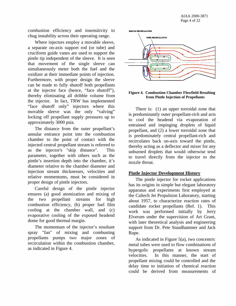
The momentum of the injector’s resultantspray "fan" of mixing and combustingpropellants pumps two major zones ofrecirculation within the combustion chamber,as indicated in Figure 4.
There is: (1) an upper torroidal zone thatis predominantly outer propellant-rich and actsto cool the headend via evaporation ofentrained and impinging droplets of liquidpropellant, and (2) a lower torroidal zone thatis predominately central propellant-rich andrecirculates back on-axis toward the pintle,thereby acting as a deflector and mixer for anyunburned droplets that would otherwise tendto travel directly from the injector to thenozzle throat.
Pintle Injector Development HistoryThe pintle injector for rocket applications
has its origins in simple but elegant laboratoryapparatus and experiments first employed atthe Caltech Jet Propulsion Laboratory, startingabout 1957, to characterize reaction rates ofcandidate rocket propellants (Ref. 1). Thiswork was performed initially by JerryElverum under the supervision of Art Grant,with later theoretical analysis and engineeringsupport from Dr. Pete Staudhammer and JackRupe.
As indicated in Figure 5(a), two concentricmetal tubes were used to flow combinations ofhypergolic propellants at known streamvelocities. In this manner, the start ofpropellant mixing could be controlled and thedelay time to initiation of chemical reactioncould be derived from measurements of
Figure 4. Combustion Chamber Flowfield Resultingfrom Pintle Injection of Propellants

AIAA 2000-3871Page 5 of 22
downstream thermocouples, with knowndistances and flow velocities.
Early experimental data revealed that alarge degree of uncertainty in timing thechemical reaction rates was due to the poormixing between the annular flow streams,especially with nearly matched flow velocities(~ zero shear mixing). This was exacerbatedby wake effects from the inner tube’s wallend and by the well-known “blow apart”characteristic of hypergolic propellants. Theinnovative solution to this problem, attributedto Elverum (Ref. 1), was to place a tip at theend of the innermost tube (attached to aninternal cruciform support) that would forcethis propellant stream to turn radial, therebyinsuring a definite point of intense mixing ofthe two propellants. This design refinement isshown in Figure 5(b).
While this apparatus proved quite useful incharacterizing reaction rates of lower energyhypergolics (e.g., RFNA/UDMH) to sub-
millisecond resolution, it proved impracticalwith higher energy hypergolics (e.g.,N2O4/MMH) due to their extremely shortreaction times. Reactions were observed to benearly instantaneous at the point ofimpingement. This laboratory equipment,however, showed a possible path todeveloping a new type of injector withdemonstrated high mixing efficiency. Indeed,later experiments at JPL featured the tippedinner tube protruding beyond the exit plane ofthe outermost tube in order to studycombustion phenomena without destroyingthe outer tube . . . thus, the basic pintleinjector was born, Figure 5(c).
Staudhammer is credited with developingthe “toothed” injector concept. As related toone of the authors (Ref. 1), he was looking fora way to further improve upon the alreadygood mixing and decided that having “slots”of one propellant penetrating into the other,outermost propellant would accomplish this.In an expedient manner, he had a technicianmake multiple hacksaw cuts across the end ofan available inner tube and, indeed,subsequent tests of this new end configurationshowed a substantial improvement in mixingefficiency.
By about 1960, Grant, Elverum andStaudhammer had moved to the newly-formedSpace Technology Laboratories, Inc. (nowTRW, Inc.) to pursue applied development ofmonopropellant and bipropellant rocketengines. It was at STL that the pintle injectorwas finally developed into a design usable inrocket engines. TRW’s first IR&D reportingon the pintle injector is for CY 1961 (Ref. 2),from which Figure 6 has been extracted. Thisshows the variety of different pintle injectorgeometries that were then being evaluated.Subsequently, the pintle injector design wasmatured and fully developed by a number ofTRW personnel (inc. Elverum, Staudhammer,Voorhees, Burge, Van Grouw, Bauer andHardgrove), adding such features as throttling,rapid pulsing capability and face shutoff.
Figure 5. Evolution of JPL Laboratory Apparatusfor Studying Reaction Rates andCombustion Phenomena of HypergolicPropellants

AIAA 2000-3871Page 6 of 22
The pintle injector design was quicklyadapted to throttling applications due to itsunique ability to retain performance andcombustion stability across a wide range ofoperating conditions. Indeed, the first flightuse of a pintle injector rocket engine was the10:1 throttling Lunar Module Descent Engineused on the Apollo program (see “EarlyApplications” below). A US patent(#3,699,772) for invention of the pintleinjector was granted to Gerry Elverum,assigned to TRW and made public in October1972.
Pintle Engine Design Fundamentals: AComparison with Typical Rocket Designs
Typical injectors for rocket engines consistof multiple, separate injection orificesdistributed more or less uniformly across thediameter of the engine’s headend. Incomparison, the pintle injector injectspropellants only at a relatively small arealocated at the center of the headend. Andwhereas conventional injectors createpropellant mixing in a planar zoneimmediately adjacent to the headend, thepintle injector creates a torroidal mixing zonethat is significantly removed from thechamber headend. As was shown in Figure 4,
the pintle injector therefore creates acombustion chamber flowfield that issignificantly different from that ofconventional rocket engine injectors. Thisleads to operating characteristics favoringcombustion stability and performance, whichare summarized in Table 1.
One extraordinary benefit of suchfundamental characteristics is that the pintleinjector has been proven to be scalable over awide range of thrust level and differentpropellant combinations without any need forstability augmentation, such as acousticcavities or baffles. There has never been aninstance of acoustic instability observed in aTRW pintle injector rocket engine.
Another major benefit is that the pintleinjector has demonstrated the ability toconsistently deliver high performance(typically 96–99% of theoretical combustionperformance, c*) with proper design andhardware buildup.
In comparison with conventional rocketengines operating at the same chamberpressure and thrust level, pintle rocket enginesare generally longer in physical length andhigher in chamber contraction ratio (bothbeing required to support the chamber’s majorrecirculation zones).
Figure 6. Early Designs of Pintle Injector Configurations Evaluated at Space Technology Laboratories, Inc.(now TRW, Inc.), extracted from Ref. 2.

AIAA 2000-3871Page 7 of 22
ParameterChamber Flow Pattern in
Typical Liquid RocketChamber Flow Pattern in
TRW Pintle Rocket
Propellant injection Distributed across injector face Only at central location
Fuel and oxidizerinjection geometry
Multiple intersecting or shearingpropellant streams; intersectingstreams are of like or unlikepropellants
Single annular outer sheet of onepropellant impinges on (a) multipleradial “spokes” of other propellant, or(b) thin radial fan of other propellant
Fuel and oxidizercollision geometry
In plane immediately adjacent toinjector face
In torus significantly offset from injectorface
Droplet trajectories Approximately axial down chamber Initially at large angle to chamber axis
Chamber recirculation None Two major recirculation zones inchamber
Droplet vaporizationand combustion
Proceed in planar fashion downchamber length
Proceed along axially symmetric, buthighly non-planar, contours in chamber
Secondary dropletbreakup
Comparatively small due to axial flowand homogeneous distribution
Comparatively large due to wallimpingement and recirculation zones
In passing throughchamber, droplets see:
Little “relative wind” away frominjector face (pressure perturbationsthus cause large change in energyrelease rate)
Large “relative wind” throughoutchamber (pressure perturbations thuscause only small change in energyrelease rate)
Energy release zonegeometry
Uniform and planar across chamberdiameter (facilitates acoustically-coupled combustion instability)
Radially-varying and canted downand across chamber—together withstable zones having different gasproperties (O/F, MW, gamma and T)— serve to prevent acoustic instabilities
Chamber for optimumcombustion performance
Is relatively short and has relativelysmall contraction ratio
Is relatively long and has relativelyhigh contraction ratio
Wall film cooling Established by separate injectionports
Established by pintle injector “tuning”,eliminating need for separate ports
Injection meteringorifices
Relatively small and contaminationsensitive
Relatively large and insensitive tocontamination
Table 1. Comparison of Key Engine Operating Parameters for TypicalLiquid Rocket Engines versus TRW’s Pintle Rocket Engine
AIAA 2000-3871Page 8 of 22
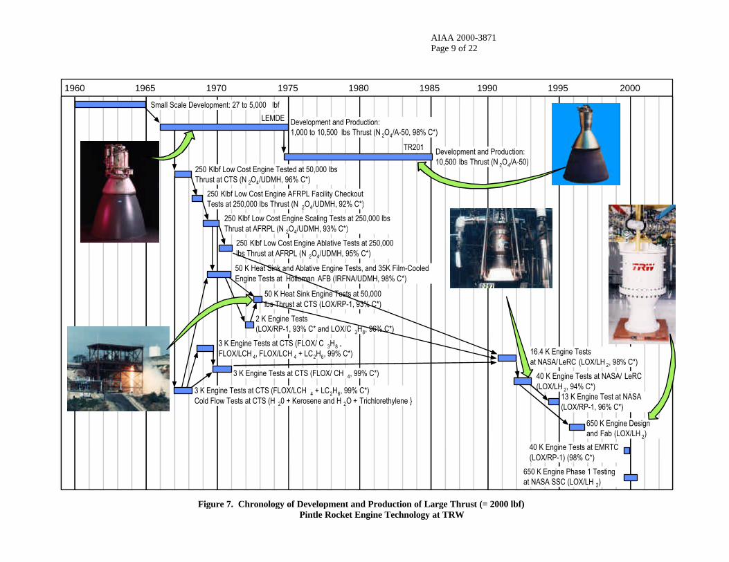
Pintle Engine Development and ProductionHistory
Figure 7 (next page) summarizes thedevelopment and production history of highthrust (=2000 lbf) pintle engines programs thathave occurred at TRW over the last 40 years.
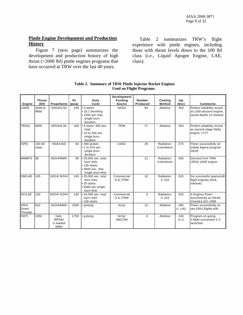
Table 2 summarizes TRW’s flightexperience with pintle engines, includingthose with thrust levels down to the 100 lbfclass (i.e., Liquid Apogee Engine, LAE,class).
Table 2. Summary of TRW Pintle Injector Rocket EnginesUsed on Flight Programs
EngineThrust
(lbf) PropellantsPc
(psia)DutyCycle
DevelopmentFundingSource
NumberProduced
CoolingMethod
Isp(Sec) Comments
LMDE 1000 to9850
N2O4/A-50 100 • 3 starts• 10:1 throttling• 1000 sec max single burn duration
NASA 84 Ablative 303 Perfect reliability recordas LEM descent engine,saved Apollo 13 mission
TR201 9900 N2O4/A-50 100 • 5 starts, 500 sec total• 10 to 350 sec single burn duration
TRW 77 Ablative 303 Perfect reliability recordas second stage Deltaengine 77/77
ISPS 100 lbfclass
HDA/USO 94 • 300 pulses• 1 to 570 sec. single burn duration
LMSC 28 Radiation,Columbium
272 Flown successfully onorbital Agena program28/28
MMBPS 88 N2O4/MMH 90 • 25,000 sec. total burn time• 130 starts• 9000 sec. max single burn time
21 Radiation,Columbium
305 Derived from TRWURSA 100R engine
DM/LAE 105 N2O4/ N2H4 100 • 25,000 sec. total burn time• 20 starts• 6000 sec single burn time
CommercialG.E./TRW
10 Radiation,C-103
315 Six successful spacecraftflight engines (Anik,Intelsat)
AC/LAE 120 N2O4/ N2H4 100 • 24,000 sec. total burn time• 100 starts
CommercialG.E./TRW
6 Radiation,C-103
322 4 Engines flownsuccessfully on NASAChandra S/C-1999
ERISDivertThruster
910 N2O4/MMH 1600 • pulsing Army 12 Ablative 284(ε =16)
Flown successfully ontwo ERIS flights-4/flt
FMTI 1050 Gels:IRFNA/
C-loadedMMH
1750 • pulsing Army/AMCOM
6 Ablative 240(s.l.)
Program on-going;2 flight successes in 2launches
AIAA 2000-3871Page 9 of 22
Figure 7. Chronology of Development and Production of Large Thrust (= 2000 lbf)Pintle Rocket Engine Technology at TRW
1960 1965 1970 1975 1980 1985 1990 1995 2000
Small Scale Development: 27 to 5,000 lbf
Development and Production:1,000 to 10,500 lbs Thrust (N 2O4/A-50, 98% C*)
LEMDE
TR201 Development and Production:10,500 lbs Thrust (N 2O4/A-50)
250 Klbf Low Cost Engine Tested at 50,000 lbsThrust at CTS (N 2O4/UDMH, 96% C*)
250 Klbf Low Cost Engine AFRPL Facility CheckoutTests at 250,000 lbs Thrust (N 2O4/UDMH, 92% C*)
250 Klbf Low Cost Engine Scaling Tests at 250,000 lbsThrust at AFRPL (N 2O4/UDMH, 93% C*)
250 Klbf Low Cost Engine Ablative Tests at 250,000lbs Thrust at AFRPL (N 2O4/UDMH, 95% C*)
50 K Heat Sink and Ablative Engine Tests, and 35K Film-CooledEngine Tests at Holloman AFB (IRFNA/UDMH, 98% C*)
50 K Heat Sink Engine Tests at 50,000lbs Thrust at CTS (LOX/RP-1, 93% C*)
2 K Engine Tests(LOX/RP-1, 93% C* and LOX/C 3H8, 96% C*)
3 K Engine Tests at CTS (FLOX/ C 3H8 ,FLOX/LCH 4, FLOX/LCH 4 + LC2H6, 99% C*)
3 K Engine Tests at CTS (FLOX/ CH 4, 99% C*)
3 K Engine Tests at CTS (FLOX/LCH 4 + LC2H6, 99% C*)Cold Flow Tests at CTS (H 20 + Kerosene and H 2O + Trichlorethylene }
16.4 K Engine Testsat NASA/ LeRC (LOX/LH 2, 98% C*)
40 K Engine Tests at EMRTC(LOX/RP-1) (98% C*)
650 K Engine Designand Fab (LOX/LH 2)
40 K Engine Tests at NASA/ LeRC(LOX/LH 2, 94% C*)
650 K Engine Phase 1 Testingat NASA SSC (LOX/LH 2)
13 K Engine Test at NASA(LOX/RP-1, 96% C*)

AIAA 2000-3871Page 10 of 22
Early ApplicationsThe first experimental pintle rockets tested
at TRW Space Technology Laboratories werethe MIRA 500 (a 25 to 500 lbf variable thrustengine), originating in December 1961, andthe MIRA 5000 (a 250 to 5000 lbf variablethrust engine), originating in May 1962,shown in Figures 8 and 9 respectively. TheseIR&D units led to development of the backupSurveyor Vernier Engine, a.k.a. the MIRA150A (a 30 to 150 lbf variable thrust enginebuilt for JPL starting in 1963) and the famousApollo Lunar Excursion Module DescentEngine (built for NASA/Grumman starting in1963). These units are shown in Figures 10and 11, respectively.
Figure 8. Test Firing of Earliest TRW Pintle InjectorEngine, a Water-Cooled MIRA 500
Figure 9. Test Firing of Ablative-Cooled MIRA 5000 Figure 11. Apollo Lunar Excursion ModuleDescent Engine
Figure 10. MIRA 150A Engine
AIAA 2000-3871Page 11 of 22
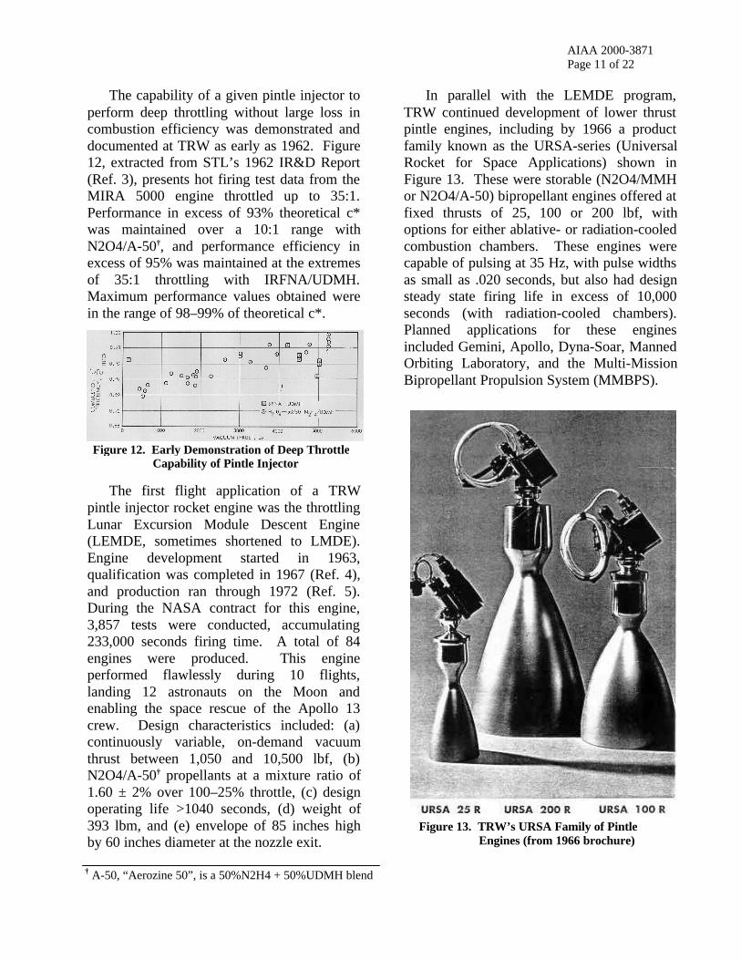
The capability of a given pintle injector toperform deep throttling without large loss incombustion efficiency was demonstrated anddocumented at TRW as early as 1962. Figure12, extracted from STL’s 1962 IR&D Report(Ref. 3), presents hot firing test data from theMIRA 5000 engine throttled up to 35:1.Performance in excess of 93% theoretical c*was maintained over a 10:1 range withN2O4/A-50†, and performance efficiency inexcess of 95% was maintained at the extremesof 35:1 throttling with IRFNA/UDMH.Maximum performance values obtained werein the range of 98–99% of theoretical c*.
The first flight application of a TRWpintle injector rocket engine was the throttlingLunar Excursion Module Descent Engine(LEMDE, sometimes shortened to LMDE).Engine development started in 1963,qualification was completed in 1967 (Ref. 4),and production ran through 1972 (Ref. 5).During the NASA contract for this engine,3,857 tests were conducted, accumulating233,000 seconds firing time. A total of 84engines were produced. This engineperformed flawlessly during 10 flights,landing 12 astronauts on the Moon andenabling the space rescue of the Apollo 13crew. Design characteristics included: (a)continuously variable, on-demand vacuumthrust between 1,050 and 10,500 lbf, (b)N2O4/A-50† propellants at a mixture ratio of1.60 ± 2% over 100–25% throttle, (c) designoperating life >1040 seconds, (d) weight of393 lbm, and (e) envelope of 85 inches highby 60 inches diameter at the nozzle exit.
In parallel with the LEMDE program,TRW continued development of lower thrustpintle engines, including by 1966 a productfamily known as the URSA-series (UniversalRocket for Space Applications) shown inFigure 13. These were storable (N2O4/MMHor N2O4/A-50) bipropellant engines offered atfixed thrusts of 25, 100 or 200 lbf, withoptions for either ablative- or radiation-cooledcombustion chambers. These engines werecapable of pulsing at 35 Hz, with pulse widthsas small as .020 seconds, but also had designsteady state firing life in excess of 10,000seconds (with radiation-cooled chambers).Planned applications for these enginesincluded Gemini, Apollo, Dyna-Soar, MannedOrbiting Laboratory, and the Multi-MissionBipropellant Propulsion System (MMBPS).
Figure 13. TRW’s URSA Family of PintleEngines (from 1966 brochure)
† A-50, “Aerozine 50”, is a 50%N2H4 + 50%UDMH blend
Figure 12. Early Demonstration of Deep ThrottleCapability of Pintle Injector
AIAA 2000-3871Page 12 of 22
Two other early, low thrust pintle enginesof historical note were the Lunar HopperEngine (a 12–180 lbf variable thrust, MON-10/MMH engine developed in 1965 forNASA/MSFC in support of the MannedFlying Vehicle program) and the ApolloCommon Reaction Control System Engine,a.k.a. C-1 (a 100 lbf fixed thrust, N2O4/MMHengine developed in 1965 for multipurposeattitude control on such programs as Apollo,Gemini and Saturn IVB). The C-1 was a longlife (>2000 seconds), pulsing (up to 35 Hz),ablative engine that employed a coated Ta-Wthroat insert.
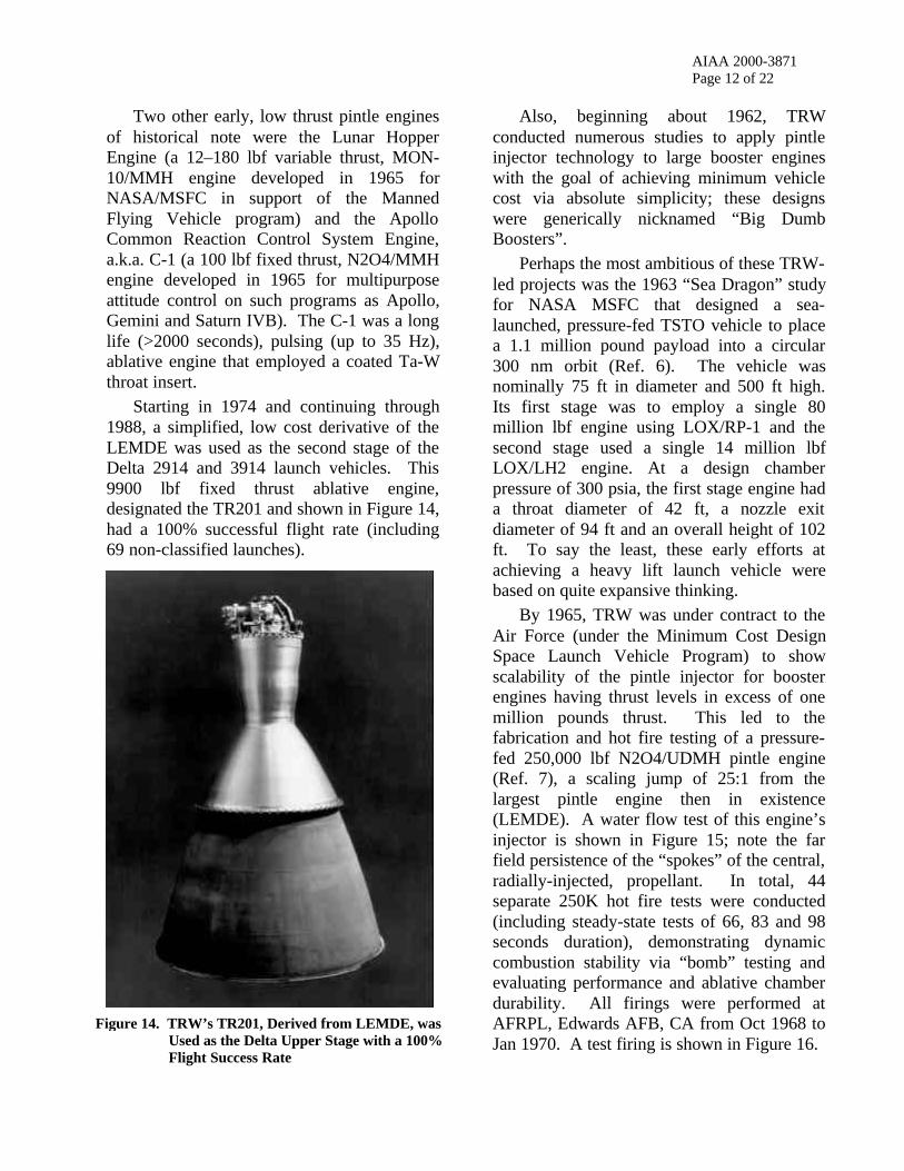
Starting in 1974 and continuing through1988, a simplified, low cost derivative of theLEMDE was used as the second stage of theDelta 2914 and 3914 launch vehicles. This9900 lbf fixed thrust ablative engine,designated the TR201 and shown in Figure 14,had a 100% successful flight rate (including69 non-classified launches).
Also, beginning about 1962, TRWconducted numerous studies to apply pintleinjector technology to large booster engineswith the goal of achieving minimum vehiclecost via absolute simplicity; these designswere generically nicknamed “Big DumbBoosters”.
Perhaps the most ambitious of these TRW-led projects was the 1963 “Sea Dragon” studyfor NASA MSFC that designed a sea-launched, pressure-fed TSTO vehicle to placea 1.1 million pound payload into a circular300 nm orbit (Ref. 6). The vehicle wasnominally 75 ft in diameter and 500 ft high.Its first stage was to employ a single 80million lbf engine using LOX/RP-1 and thesecond stage used a single 14 million lbfLOX/LH2 engine. At a design chamberpressure of 300 psia, the first stage engine hada throat diameter of 42 ft, a nozzle exitdiameter of 94 ft and an overall height of 102ft. To say the least, these early efforts atachieving a heavy lift launch vehicle werebased on quite expansive thinking.
By 1965, TRW was under contract to theAir Force (under the Minimum Cost DesignSpace Launch Vehicle Program) to showscalability of the pintle injector for boosterengines having thrust levels in excess of onemillion pounds thrust. This led to thefabrication and hot fire testing of a pressure-fed 250,000 lbf N2O4/UDMH pintle engine(Ref. 7), a scaling jump of 25:1 from thelargest pintle engine then in existence(LEMDE). A water flow test of this engine’sinjector is shown in Figure 15; note the farfield persistence of the “spokes” of the central,radially-injected, propellant. In total, 44separate 250K hot fire tests were conducted(including steady-state tests of 66, 83 and 98seconds duration), demonstrating dynamiccombustion stability via “bomb” testing andevaluating performance and ablative chamberdurability. All firings were performed atAFRPL, Edwards AFB, CA from Oct 1968 toJan 1970. A test firing is shown in Figure 16.
Figure 14. TRW’s TR201, Derived from LEMDE, wasUsed as the Delta Upper Stage with a 100%Flight Success Rate

AIAA 2000-3871Page 13 of 22
In the period 1969 to 1971, TRW alsofabricated and conducted demonstration testfirings on 35,000 and 50,000 lbf pressure-fedpintle engines with the goal of using thesestorable propellant rockets to power highspeed sleds at Holloman Air Force Base.
Design RefinementsBeginning in the early 1980’s, a series of
design refinements were applied to the pintleinjector to adapt it to a wide variety ofdeveloping, challenging applications.
First, improving sensor, guidance andmissile technologies indicated that ballisticmissile defense with “hit-to-kill” missile
interceptors was possible. However, suchmissiles required attitude control and lateral(“divert”) rockets that could provideexceptionally fast and repeatable pulses oncommand. Certain applications also requiredlinear throttling capability in addition topulsing. By conveniently enabling shutoff ofpropellants at their injection point into thecombustion chamber (using a movablesleeve), the pintle injector provided greatlyimproved pulse response by eliminatinginjector “dribble volume” effects. A pintleinjector with the face shutoff feature is shownin Figure 17.
A very compact, 8,200 lbf N2O4/MMHengine employing this feature is shown inFigure 18. This engine was developed startingin 1981 as a pitch and yaw thruster for theArmy SENTRY missile program. Tightpackaging into the generally cylindrical shapeof such missiles required that a “turned flow”nozzle be employed (here the flow was turnedabout 110° off chamber axis). This particularrocket application also required a slot nozzleto produce jet interaction effects that increasedeffective vehicle side thrust for operationwithin the atmosphere. This pintle injectorengine, utilizing cavitating venturi controlvalves in a manner similar to LEMDE, couldthrottle over a 19:1 thrust range with ±8%linearity and could deliver repeatable “on”pulses as small as 8 milliseconds (to 90% s.s.
Figure 15. Water Flow Test of Pintle Injectorfor Air Force 250,000 lbf Engine
Figure 16. Hot Fire Test of Pressure-Fed250,000 lbf Ablative Engine
Figure 17. Face Shutoff Pintle Injector inClosed Position
AIAA 2000-3871Page 14 of 22
Pc) at any thrust level. It operated at 2200psia chamber pressure to achieve small sizeand light weight (<13 lbm). Deliverablecombustion efficiency was 98% of theoreticalat full thrust, rolling off to 94% at 1/10 throttleand to 71% at 1/19 throttle (Ref. 8).
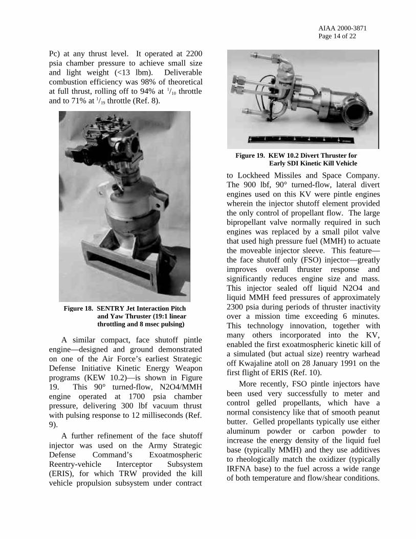
A similar compact, face shutoff pintleengine—designed and ground demonstratedon one of the Air Force’s earliest StrategicDefense Initiative Kinetic Energy Weaponprograms (KEW 10.2)—is shown in Figure19. This 90° turned-flow, N2O4/MMHengine operated at 1700 psia chamberpressure, delivering 300 lbf vacuum thrustwith pulsing response to 12 milliseconds (Ref.9).
A further refinement of the face shutoffinjector was used on the Army StrategicDefense Command’s ExoatmosphericReentry-vehicle Interceptor Subsystem(ERIS), for which TRW provided the killvehicle propulsion subsystem under contract
to Lockheed Missiles and Space Company.The 900 lbf, 90° turned-flow, lateral divertengines used on this KV were pintle engineswherein the injector shutoff element providedthe only control of propellant flow. The largebipropellant valve normally required in suchengines was replaced by a small pilot valvethat used high pressure fuel (MMH) to actuatethe moveable injector sleeve. This feature—the face shutoff only (FSO) injector—greatlyimproves overall thruster response andsignificantly reduces engine size and mass.This injector sealed off liquid N2O4 andliquid MMH feed pressures of approximately2300 psia during periods of thruster inactivityover a mission time exceeding 6 minutes.This technology innovation, together withmany others incorporated into the KV,enabled the first exoatmospheric kinetic kill ofa simulated (but actual size) reentry warheadoff Kwajaline atoll on 28 January 1991 on thefirst flight of ERIS (Ref. 10).
More recently, FSO pintle injectors havebeen used very successfully to meter andcontrol gelled propellants, which have anormal consistency like that of smooth peanutbutter. Gelled propellants typically use eitheraluminum powder or carbon powder toincrease the energy density of the liquid fuelbase (typically MMH) and they use additivesto rheologically match the oxidizer (typicallyIRFNA base) to the fuel across a wide rangeof both temperature and flow/shear conditions.
Figure 18. SENTRY Jet Interaction Pitchand Yaw Thruster (19:1 linearthrottling and 8 msec pulsing)
Figure 19. KEW 10.2 Divert Thruster forEarly SDI Kinetic Kill Vehicle

AIAA 2000-3871Page 15 of 22
Gel propellants provide nearly the energydensity of solid propellants and thecontrollability of liquid propellants, but withmuch safer storage, handling and operatingcharacteristics. Unlike either solids or liquids,gel propellants have been shown to beinsensitive munitions (IM) compliant. Forgelled propellants to be used on rocketsneeding energy management, face shutoff ismandatory to prevent dry-out of the baseliquid propellants during off times betweenpulses, which would otherwise result in thesolids within the gels plugging the injectorpassages.
FSO pintle injectors have been used on avariety of programs, as summarized in Table3. Of particular note, the McDonnell DouglasAdvanced Crew Escape Seat – Experimental(ACES-X) program and it’s successor, the GelEscape System Propulsion (GESP) program,refined the FSO pintle injector (with ahydraulic servo valve acting as injector pilotvalve) to the point that 2 millisecond pulsescould be repeatedly delivered at >100 Hz on a1700 lbf rocket engine using gelled oxidizerand aluminum-loaded gel fuel propellants
(Ref. 11). A cross-section sketch of the FSOinjector from the GESP program is shown inFigure 20. The GESP engine operated at acombustion chamber pressure of 2500 psia,the highest of any pintle engine that has everbeen tested. The FSO injector on this enginesealed against supply pressures ofapproximately 3000 psia.
Figure 20. Face Shutoff-Only (FSO) PintleInjector Concept Used on GESP
Table 3. Summary of Major Applications of TRW Face Shutoff Pintle Engines
AdvancedThrottling SlurryEngine (ATSE)
SENTRYPitch & YawEngine
KEW 10.2Divert Thruster
ACES-X/ GESP ERISLateral Thruster
FMTI
Propellants CLF3/ NOTSGEL-A N2O4/MMH andgel IRFNA/ gel MMH(Al-loaded)
N2O4/MMH gel IRFNA/ gel MMH(Al-loaded)
N2O4/ MMH gel IRFNA/ gel MMH(C-loaded)
Full Thrust (lbf) 5000 (s.l.) 8200 (s.l.) 300 (vac) 1500/1700 (s.l.) 910 (vac) 1050 (s.l.)
Full Pc (psia) 1000 2200 1700 2500 1600 1750
Throttle Range 7:1 19:1 fixed thrust fixed thrust fixed thrust fixed thrust
UpstreamValve
servo-piloted,hydraulically operated,linearly positioned,cavitating venturi,linked biprop
servo-piloted,hydraulically/MMHoperated, linearlypositioned, cavitatingventuri, linked biprop
solenoid-piloted,MMH operated,on-off,linked biprop
None None None
Pintle InjectorType
continuously variablearea, mechanicallylinked to valvestroke, only fuel sidefully shutoff
continuouslyvariable area,spring vs. pressurebalanced
on/off,pressure opened,spring closed
FSO, on/off,pressure opened,spring closed, servopilot valve, hyd oilactuated
FSO, on/off, pressureopened, springclosed, miniature3-way solenoid pilotvalve, MMH act’d
FSO, on/off, pressureopened, springclosed, miniature3-way solenoid pilotvalve, hyd oil act’d
DemonstratedPulse Widths
steady state only .008 – .600 sec .010 – 1.13 sec .002 – .800 sec .020 – 1.76 sec .115 – 1.66 sec
Comments used toothed elementfor ox injection (centerpropellant)
>150 firing tests 67 pulses and 9.4sec firing time onone engine
also tested inmockup escape seat(4 engine firing)
flown, 100%success (8/8)
flown, 100%success (2/2)

AIAA 2000-3871Page 16 of 22
Another design challenge from the mid-1980’s and early 1990’s was that of obtainingminiaturization of rocket engines. As part ofthe Air Force Brilliant Pebbles program, TRWdeveloped a very small 5 lbf N2O4/hydrazinethruster using a pintle injector. This radiation-cooled engine weighed 0.3 lbm (135 grams)and was successfully tested in August 1993,delivering >300 seconds Isp with a 150:1nozzle expansion ratio. The pintle diameterwas .066 inches and scanning electronmicroscopy was needed to verify as-builtdimensions on the .0030±.0003 inch radialmetering orifices. Figure 21 is a SEMphotograph of this pintle injector, the smallestever built.
Another major design adaptation in thistime period was use of the pintle injector withcryogenic liquid hydrogen fuel. Previously,various pintle engines had been tested withliquid oxygen or liquid fluorine-oxygen(FLOX) as the oxidizer in combination with anear-ambient temperature liquid fuel such asmethane, ethane, propane, RP-1 or hydrazine.Beginning in 1991, TRW joined withMcDonnell Douglas and NASA Lewis (nowGlenn) Research Center to demonstrate thatTRW’s pintle engine could use direct injectionof near-normal boiling point LH2 (~50 R or28 K) to simplify the design of high
performance booster engines. Attempts to usedirect injection of cryogenic hydrogen in othertypes of injectors had consistently resulted inthe onset of combustion instabilities(“screech”), so verification of the inherentcombustion stability of the pintle injector wasa key part of this effort.
In late 1991 and early 1992, a 16,000 lbfLOX/LH2 test engine was successfullyoperated at sea-level at LeRC with directinjection of liquid hydrogen and liquid oxygenpropellants (Ref. 12). A total of 67 firingswere conducted. The engine demonstratedexcellent performance, with 97% averagecombustion efficiency and total absence ofcombustion instabilities, including dynamicrecovery on five runs having radial andtangential “bomb” excitations. Although theengine used a fixed-element injector, it wasoperated at 60%, 80% and 100% thrust levelsby throttling facility propellant valves. Figure22 shows a full thrust firing on this testengine.
Subsequently, this same test engineheadend was adapted for and was successfully
Figure 22. Pintle Injector Operation with DirectInjection of LOX and 45–50 R LH2
Figure 21. Pintle Injector on Brilliant Pebbles5 lbf Engine

AIAA 2000-3871Page 17 of 22
tested with LOX/LH2 at 40,000 lbf and withLOX/RP-1 at 13,000 and 40,000 lbf.Significantly, this was accomplished bychangeout of just three† injector parts, shownin Figure 23.
This demonstrates a key feature of thepintle injector: the low cost and ease by whichit can be adapted to a change in operatingconditions or propellants. Furthermore,optimization of a given injector’s performanceis empirically obtained by simply varying thegeometries of the outer propellant’s annulargap and the central propellant’s slotgeometries (and/or continuous gap, if used),two of the three parts shown in Figure 23.
Recent ApplicationsWithin the last ten years the pintle injector
has continued to be used across a diverserange of applications, with much of thehardware heritage traceable to work describedabove.
In the field of space propulsion, theURSA-series of radiation cooled engines—which led to the MMBPS and ISPS engines ofthe 1970’s—provided the heritage for theN2O4/hydrazine (“dual mode”) TR306 liquidapogee engines (LAEs) used on the Anik E-1/E-2 and Intelsat K spacecraft in 1991–1992and most recently the dual mode TR308 LAEsused to place the NASA Chandra spacecrafton final orbit in August 1999. The TR308,
shown in Figure 24, delivers 322 seconds ofvacuum Isp using a radiation-cooledcolumbium chamber. A next-generation LAEdesign, the TR312, which uses a rheniumcombustion chamber has been demonstrated todeliver 325 seconds Isp with N2O4/MMH and330 seconds Isp with N2O4/hydrazine.
The early FSO injector and gel propellantdevelopment work of late 1980’s/early 1990’sled to the world’s first missile flights usinggelled oxidizer and gelled fuel propellants.These were successfully performed on theArmy/AMCOM Future Missile TechnologyIntegration (FMTI) program, with the firstflight in March 1999 (Ref. 13) and the secondflight in May 2000. The 1050 lbf, 1750 psiachamber pressure engine, shown in Figure 25,is extremely lightweight (1.6 lbm, including0.1 lbm solenoid valve). It is an ablativeengine using a miniature solenoid valve tohydraulically control a FSO injector whichmeters gelled IRFA and carbon-loaded gelledMMH propellants for pulse-width modulatedenergy management during time-of-flight.
† On the 40K LOX/RP-1 engine, it was found that changing the4 inch diameter pintle sleeve to 5 inch diameter permitted anoxidizer injection slot geometry delivering higher performance
Figure 23. Pintle Tip, Oxidizer Orifice Ring and FuelGap Ring from 16K LOX/LH2 Engine
Figure 24. TR308 N2O4/Hydrazine Liquid ApogeeEngine Used to Place NASA ChandraSpacecraft on Final Orbit in Aug 1999

AIAA 2000-3871Page 18 of 22
In the area of booster engines, TRWhas continued development of large LOX/LH2pintle engines to the point that a 650,000 lbftest engine is currently undergoing pre-hot firecheckout testing at the NASA Stennis SpaceCenter E-1 test stand. This engine, shown inFigure 26, represents a 16:1 scale-up from thelargest previous LOX/LH2 pintle engine andabout a 3:1 scale-up from the largest previouspintle engine ever tested, the 250,000 lbfN2O4/UDMH Air Force demo engine. Aswith the previous 16K and 40K LOX/LH2pintle engines, the 650K engine will use directinjection of near-normal boiling point LH2.An extensive test series, includingperformance mapping, ablative durabilitydemonstration and combustion stability (i.e.,“bomb” tests) demonstration, has beenplanned for this engine. Testing will initiallyinvolve short (<10 second) pressure-fedfirings, with later pump-fed firingsdemonstrating full mission duty cycleoperation (>200 seconds). Additional detailson this engine’s development, features and testplans are given in Reference 14. Forcomparison, this injector’s pintle diameter is22 inches, by far the largest built to date.
Summary of Design FeaturesThe pintle injector design has been proven
to be amazingly flexible and adaptable acrossa wide range of conditions. The features andoperating characteristics of pintle engines aresummarized here.
High Performance. With proper designand manufacturing—in some cases assisted byempirical “tuning’ of injection geometries—pintle injectors can typically deliver 96–99%of theoretical combustion performance (asmeasured by characteristic velocity, or c*).Figure 27 summarizes combustion efficiencyfor some of the major pintle engine programsat TRW. Included in this figure are somequick, low cost demonstration engines wherebudgets or schedules prevented optimizationof injector parameters.
Figure 25. FMTI Flight Engine (uses FSO pintleinjector to control gel propellants)
Figure 26. The 650,000 lbf LOX/LH2 Low Cost PintleEngine (LCPE) . . . the Largest PintleEngine Built to Date

AIAA 2000-3871Page 19 of 22
Scalability. As also indicated in Figure27, the basic pintle injector design has beendemonstrated to be scalable over a range of50,000:1 in thrust. With the expected,imminent firing of the 650K LOX/LH2 engineon the SSC E-1 test stand, this range will beextended to 130,000:1.
Inherent Combustion Stability. Threemajor, non-exclusive theories have beendeveloped to explain the inherent combustionstability of the pintle injector:1) lack of energy release availability at any
antinode for all possible chamber acousticmodes (classical theory of combustioninstability; Rayleigh, et. al.),
2) unvaporized, liquid droplets within thechamber’s recirculating flowfields alwaysexperience a relative wind of combustiongases (C. Johnson, SEA),
3) the zones of highly varying sound speedwithin the combustion chamber (due tovarying O/F, T, MW and cp/cv) disperseand dampen acoustic waves before onsetof resonance (F. Stoddard, TRW).
Table 4 summarizes “bomb” tests performedon various pintle engines, each of whichdemonstrated complete dynamic combustionstability and critically damped recovery fromthe induced pressure transient.
Propellants Thrust Level(Klbf)
Stability Test Type[grains RDX]
LOX/LH2 16 5 pulse gun tests(2 radial, 2 tangential,1 combined) [20–60]
LOX/LH2 40 5 pulse gun tests (allradial & tangentialcombined) [40 + 40]
LOX/RP-1 13 5 pulse gun tests(2 radial, 1 tangential,1 combined, 1 non-directional) [20–80]
LOX/RP-1 50 4 “bomb” tests;<15 msec damping
N2O4/A-50 1, 2.5, 3, 4,5, 10 and
10.5(LEMDE)
31 non-directionalRDX bomb tests withpressure spikes>150% Pc s.s.(including ND bombslocated on face ofpintle tip and atnozzle throat) [5–40]
N2O4/UDMH 250 13 pulse gun tests(7 radial and 6tangential) and 8 non-directional bombtests [40–120]
N2O4/UDMH 50(throttled
250K engine)
2 non-directionalbomb tests, <15 msecdamping [20–30]
Table 4. Summary of Dynamic Stability Tests Performedon Various Pintle Injector Engines
Figure 27. Summary of Combustion Efficiencies Measured on Major Pintle Engine Programs

AIAA 2000-3871Page 20 of 22
Range of Propellants Tested. Pintleinjectors have successfully operated with 25different combinations of propellants, whichare summarized in Table 5.
LOX/H2(l) LOX/RP-1
LOX/C3H8 LOX/N2H4
LOX/ETHANOL GOX/ETHANOL
FLOX/CH4(l) FLOX/CH4(g)
FLOX/C3H8(l) FLOX/CH4+C2H6(l)
N2O4-MON3/MMH N2O4-MON3/N2H4
N2O4/UDMH N2O4/A-50
ClF3/N2H4 ClF3/NOTSGELA
F2(l)/N2H4 MON10/MMH
IRFNA/UDMH IRFNA/JP4
IRFNA/NOTSGEL-A HDA/USO
Gelled IRFNA/Gelled MMH+60%Al
Gelled IRFNA/Gelled MMH+60%C
Coal Dust/Air
Throttling Ability. As discussedpreviously, single pintle injectors haveoperated over throttle ranges as high as 35:1while still retaining high combustionefficiency. TRW’s most famous throttlingengine is the man-rated Apollo LEMDE,which provided 10:1 throttling capability toperform lunar landings. A summary ofthrottling pintle engines is given in Table 6.
Simplicity. A complete pintle injector canbe made with as few as five parts, excludingthe engine headend dome and fasteners. Onlytwo simple parts need to be changed toempirically and rapidly optimize the injector’sperformance. The simple design of pintleinjector parts and their operation at benigntemperatures (except for the pintle tip) assuresease of manufacturing using non-exotic metalalloys and common machining and weldingmethods. The inherent combustion stabilityprovided by the pintle injector eliminates theneed for any headend baffles or acousticcavities and this simplifies thrust chamberconstruction, enhances reliability and reducesmanufacturing cost.
MIRA500
VariableThrustEngine
MIRA5000
VariableThrustEngine
SurveyorVernierEngine
(MIRA 150)
LunarHopperEngine
LMDescentEngine
8KEngine
AdvancedThrottling
SlurryEngine(ATSE)
SentryEngine
OMVVTE
ThrottlingCapability
20:1
500 to 25 lbf
35:1
5,200 to 150 lbf
5:1
150 to 30 lbf
15:1
180 to 12 lbf
10:1
10,000 to 1,000 lbf
15:1
8,250 to 553 lbf
7:1
5,000 to 700 lbf
19:1
8,200 to 430 lbf
10:1
130 to 13 lbf
Propellants N2O4/A-50
N2O4/N2H4
N2O4/A-50
N2O4/MMH
MON-10/MMH
MON-10/MMH
N2O4/A-50 N2O4/A-50 CLF3/NOTSGEL-A
N2O4/MMH
N2O4/MMH
Sponsor TRW IR&D
TRW IR&D
NASA/ JPL
NASA/ MSFC
NASA/Grumman
USAF/ LTV
Navy/ NWC
US Army/ Bell
NASA/ MSFC
ProgramDuration
1961-63 1962-63 1963-65 1965 1963-72 1967-68 1967-68 1981-84 1986-89
No. of Engines 1 1 16 1 84 2 1 4 2
Table 5. Propellant Combinations TestedUsing Pintle Injectors
Table 6. Summary of Major TRW Throttling Engines

AIAA 2000-3871Page 21 of 22
Design Adaptability. As discussedpreviously, the pintle injector design enablesincorporating features such as deep throttling,rapid pulsing, face shutoff with upstreamvalving, face shutoff only (FSO), directinjection of near-normal boiling point LH2,and the demonstrated ability to use gelledpropellants in pulsing applications.
Low Cost. With its inherent stability andease of optimization, the pintle injectorminimizes risk and cost for development andqualification of new engine designs. Its easeof manufacture provides for significantreductions in recurring costs, especially inbooster-class engines.
ConclusionIn the field of rocket engines, the pintle
injector is unique in its configuration,operating characteristics and performancefeatures. It is a patented technology that hasprovided the base for a diverse product line ofbipropellant rocket engines of one company,TRW (formerly Space TechnologyLaboratories), for more than 40 years.
There has never been a flight failure of apintle injector engine. Moreover, there hasnever been an instance of combustioninstability in a pintle engine during anyground or flight operations, despite scalingover a range of 50,000:1 in thrust and 250:1 inchamber pressure and operation with 25different propellant combinations, includingLOX/LH2 and F2/hydrazine.
The pintle engine has been developed,ground demonstrated and successful flownacross a wide and challenging range ofapplications, including programs of nationalimportance such as Apollo and the recentNASA Chandra “Great Observatory”spacecraft. The pintle injector has enabled theworld’s first successful flight of a missileusing gelled propellants. Even at the time ofpublication of this paper, pintle injectortechnology is being extended into a new realm
on the 650,000 lbf LOX/LH2 LCPE. Thistechnology offers the potential to dramaticallyreduce the cost of access to space “. . . for allmankind.”
References1. Personal conversation between Dr. Pete
Staudhammer and Gordon Dressler at TRW, Inc.,Redondo Beach, CA, March 2000
2. “Research of Low-Thrust Bipropellant Engines,”B. Siegel, Independent Research Program AnnualProgress Report, Calendar Year 1961, #9990-6020-RU-000, pp.VI-59 toVI-73, Space TechnologyLaboratories, Inc., Redondo Beach, CA
3. “Bipropellant Rocket Engine Research,” H.Shieber, Independent Research Program AnnualProgress Report, Calendar Year 1962, #9990-6363-RU-000, pp.VI-8 toVI-11, Space TechnologyLaboratories, Inc., Redondo Beach, CA
4. “The Descent Engine for the Lunar Module,” G.Elverum, P. Staudhammer, J. Miller, A. Hoffman,and R. Rockow, AIAA 67-521, AIAA 3rd
Propulsion Joint Specialist Conference, 17-21 July1967
5. “The Lunar Module Descent Engine – A HistoricalPerspective,” R. Gilroy and R. Sackheim, AIAA89-2385, AIAA/SAE/ASME 25th Joint PropulsionConference, 1989
6. “Study of Large Sea-Launch Space Vehicle,”Contract NAS8-2599, Space TechnologyLaboratories, Inc./Aerojet General CorporationReport #8659-6058-RU-000, Vol. 1 – Design,January 1963
7. “Injector/Chamber Scaling Feasibility Program,”G. Voorhess, Jr. and B. Morton, TRW FinalTechnical Report, AFRPL-TR-70-86, Vol. I and II,July 1970
8. “High Performance Throttling and Pulsing RocketEngine,” J. Hardgrove and H. Krieg, Jr., AIAA 84-1254, AIAA/SAE/ASME 20th Joint PropulsionConference, 11-13 June 1984
9. “KEW Divert Propulsion Technology Verificationand Risk Reduction Program,” G. Dressler, G.Giola and P. Tao, TRW Final Report on ContractF04611-85-C-0027, AFAL-TR-88-023, April 1988

AIAA 2000-3871Page 22 of 22
10. “Development and Flight Qualification of thePropulsion and Reaction Control System forERIS,” D. Fritz, G. Dressler, N. Mayer and L.Johnson, AIAA 92-3663, AIAA/SAE/ASME/ASEE 28th Joint Propulsion Conference, 6-8 July1992
11. “Gel Propulsion for the Forth Generation EscapeSystem,” D. Fritz and K. Gavitt, paper presented atthe 1993 SAFE Symposium, Las Vegas, NV, 8-10November 1993
12. “Test Results from a Simple, Low-Cost, Pressure-Fed Liquid Hydrogen/Liquid Oxygen RocketCombustor,” G. Dressler, F. Stoddard, K. Gavittand M. Klem, 1993 JANNAF Propulsion Meeting,15-18 November 1993, CPIA Pub. 602, Vol. II,pp 51-67
13. “Gelled Propellants for Tactical MissileApplications,” K. Hodge, T. Crofoot and S.Nelson, AIAA 99-2976, 35th
AIAA/ASME/SAE/ASEE Joint PropulsionConference, 20-23 June 1999
14. “TRW LCPE 650 Klbf LOX/LH2 Test Results,” K.Gavitt and T. Mueller, AIAA 2000-3853, 36th
AIAA/ASME/SAE/ASEE Joint PropulsionConference, 16-19 July 2000

AIAA 2000-3871Addendum Page 1 of 1
Addendum
1. An excellent reference for the early development work at Caltech, cited in the firstthree full paragraphs on Page 5 is:
“The Effect of Rapid Liquid-Phase Reactions on Injector Design andCombustion in Rocket Motors,” Gerard W. Elverum, Jr. and Pete Staudhammer,Jet Propulsion Laboratory, Progress Report No. 30-4, 25 August 1959
2. Commenting on the early Caltech JPL work on characterizing reactions of hypergolicreactions, Jerry Elverum provided the following comment to the paper’s authors:
“Early experimental data revealed that the speed of liquid-phase reactions at thecontact interface of hypergolic propellants generated an expanding confinedannular gas boundary which limited the effectiveness of premixing downstreamof the retracted inner tube. Subsequent experiments with stabilized impingingstreams definitely demonstrated for the first time that for highly hypergolicpropellants, this essentially instantaneous gas evolution at the contact interfacecaused major separation of oxidizer and fuel in the resulting spray pattern. Thedesire to use “pre-mixing” of hypergolic propellants in a simple concentric tubeconfiguration as a way of forcing intermixing was also shown to be severelylimited by the extreme rapidity of this interface reaction.”