TRUCTURED ANALYSIS - Masarykova univerzita ! Yourdon Modern Structured Analysis (YMSA) " Context...
59
Lecture 5 STRUCTURED ANALYSIS PB007 So(ware Engineering I Faculty of Informa:cs, Masaryk University Fall 2015 1 © Bühnová, Sochor, Ráček
Transcript of TRUCTURED ANALYSIS - Masarykova univerzita ! Yourdon Modern Structured Analysis (YMSA) " Context...

Lecture 5
STRUCTURED ANALYSIS
PB007 So(ware Engineering I Faculty of Informa:cs, Masaryk University Fall 2015
1 © Bühnová, Sochor, Ráček

Outline
² Yourdon Modern Structured Analysis (YMSA) § Context diagram (CD) § Data flow diagram (DFD)
² Data modelling § Entity relationship diagram (ERD)
² Relational database design § Normalization
2 © Bühnová, Sochor, Ráček

Yourdon Modern Structured Analysis (YMSA)
Lecture 5/Part 1
3 © Bühnová, Sochor, Ráček

E. Yourdon: Modern structured analysis
4
Environment model Behavioral model
Functional decomposition
© Bühnová, Sochor, Ráček
Events:
E1: registered E2: rolled in E3: rolled out E4: started E5: ended
Course
Teacher
Student
Data model

Environment model
² Context diagram is a special case of a data flow diagram, containing a single process representing the whole system. It emphasizes: § Terminators – people and systems communicating with the
system § Data received from the environment that shall be processed § Data produced by the system and sent to the environment § Data stores shared by the system and its terminators § System boundary
² Event list is a textual list of stimuli coming from the environment that must be responded by the system.
5 © Bühnová, Sochor, Ráček

Context diagram example
6 © Bühnová, Sochor, Ráček
Customers
orders, canceled orders
BookProduction
Accounting
Management
orders of extra prints
books to store
invoice sell report
invoice, delivery note
Book selling eshop
Account balance

Behavioral model
² Behavioral model specifies the flow of data through the modeled information system, modeling its process aspects. § It shows what kinds of information will be input to and output
from the system, where the data will come from and go to, and where the data will be stored.
§ It does not show information about the timing of processes, or information about whether processes will operate in sequence or in parallel.
² Data flow diagram (DFD) is a graphical representation of the system as a network of processes that fulfill system functions and communicate through system data.
7 © Bühnová, Sochor, Ráček

Data flow diagram (DFD)
² DFD consists of four types of elements: § Processes § Data flows § Data stores § Terminators
8 © Bühnová, Sochor, Ráček
Account update
Account
Account verification Client
withdraw command
authorized command
account balance
updated account
transaction record
Transactions archive

Processes and Data flows
² A Process models a part of the system that transforms specific inputs to outputs.
² Name of a process is a single word, phrase or simple sentence, e.g. “User authentication”. § The process name sometimes contains the name of a person,
group of people, department or device – specifying also the actor or tool of the process.
² A Data flow models a way for data transfer from one part of the system to another. § Flows can also model the transfer of physical materials.
9 © Bühnová, Sochor, Ráček

Data stores
² Data store models a static collection of data that are shared by two or more processes operating in different time. § Name is a plural of the data name going to and coming from the
data store.
10 © Bühnová, Sochor, Ráček
Answer queries
Orders
Record order order
order detail
reply
query
order
confirmation
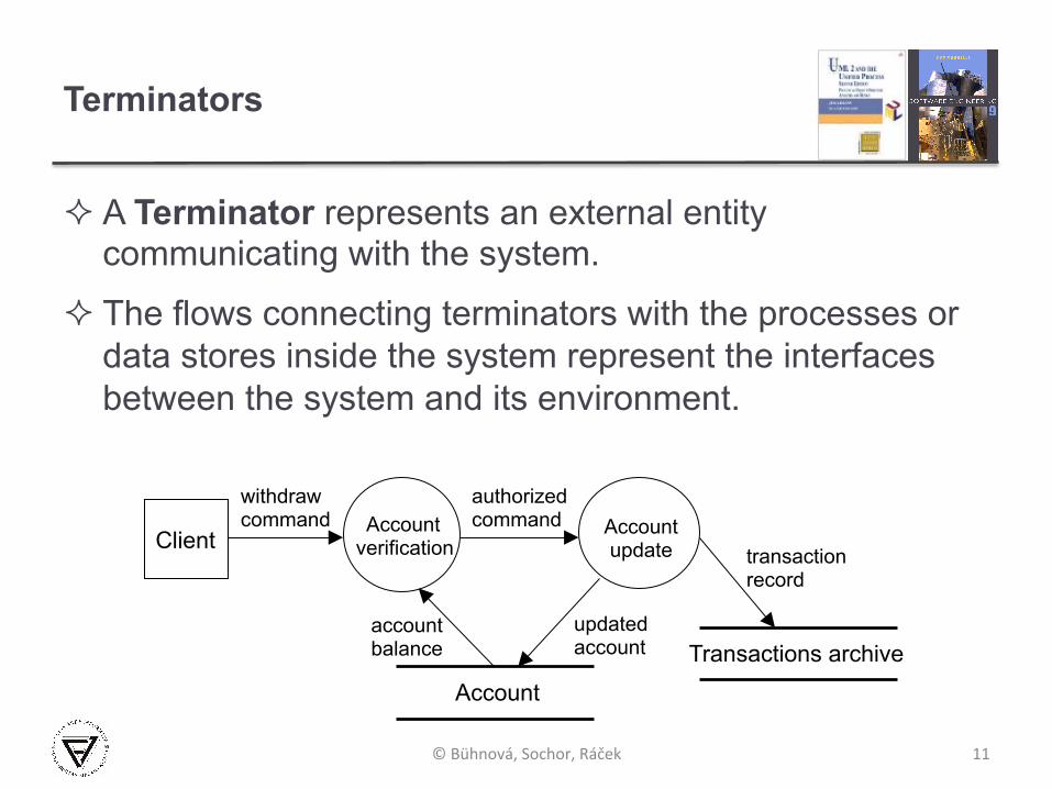
Terminators
² A Terminator represents an external entity communicating with the system.
² The flows connecting terminators with the processes or data stores inside the system represent the interfaces between the system and its environment.
11 © Bühnová, Sochor, Ráček
Account update
Account
Account verification Client
withdraw command
authorized command
account balance
updated account
transaction record
Transactions archive

Top-down and bottom-up DFD balancing
12
primary DFD 98 processes
first balancing 14 processes
system DFD 2 processes
© Bühnová, Sochor, Ráček
What are the disadvantages of the two approaches?
Data modelling
Lecture 5/Part 2
13 © Bühnová, Sochor, Ráček

Data modeling
² Defines static data structure, relationships and attributes
² Complementary to the behavior model in structured analysis; models information not covered by DFDs
² More stable and essential information comparing to DFD
² Entity-Relationship modeling § Identify system entities – both abstract (lecture) and concrete
(student) § For each entity examine – the purpose of the entity, its
constituents (attributes) and relationships among entities § Check model consistency and include data details
14 © Bühnová, Sochor, Ráček

Entity Relationship Diagram (ERD)
² Entities and their types
² Relationships and their types
² Attributes and their domains
15 © Bühnová, Sochor, Ráček
Chen's notation (concept level description)
Teacher Lecture gives
date
length
place
name contact name
1 (1,1)
N (0,8)
Teacher Lecture
(0,8) name contact
name date length place
(1,1)
Crow’s Foot notation (implementation level descript.)
gives

Entities and Entity types
² An Entity is anything about which we want to store data § Identifiable – entities can be distinguished by their identity § Needed – has significant role in the designed system § Described by attributes shared by all entities of the same type
² An Entity set is a set of entities of the same Entity type.
16
En#ty En#ty type
You Student
Your neighbor Student
Me Teacher
This PB007 lecture Lecture
Student
Lecture
Teacher
© Bühnová, Sochor, Ráček
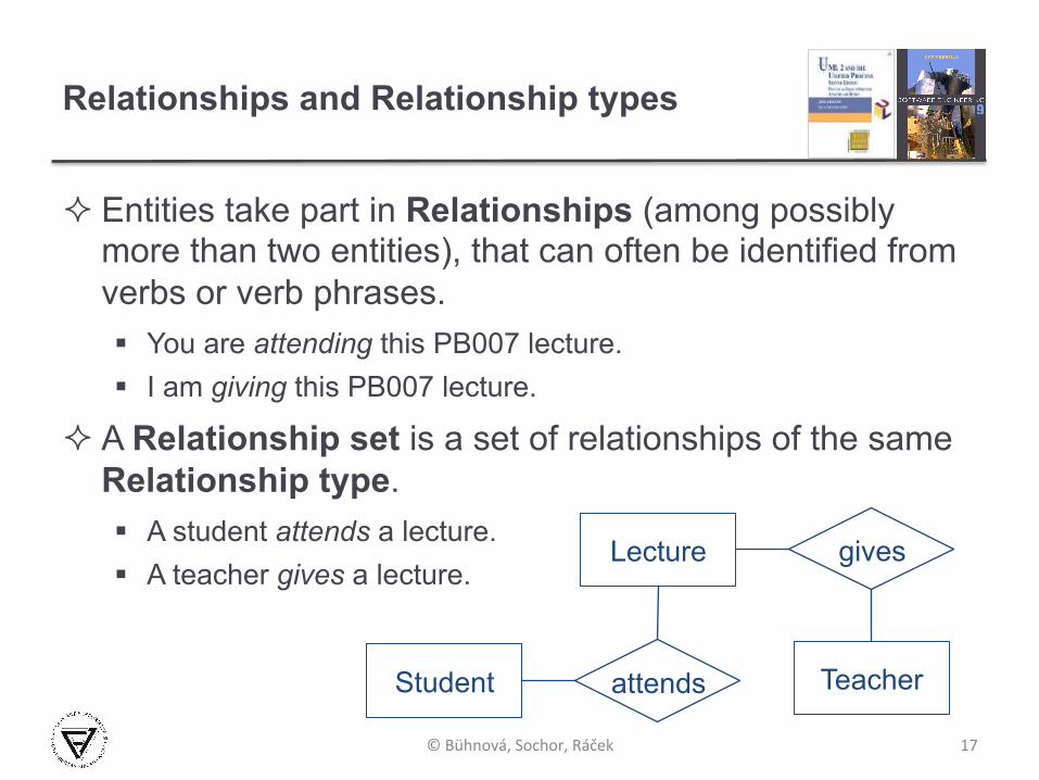
Relationships and Relationship types
² Entities take part in Relationships (among possibly more than two entities), that can often be identified from verbs or verb phrases. § You are attending this PB007 lecture. § I am giving this PB007 lecture.
² A Relationship set is a set of relationships of the same Relationship type. § A student attends a lecture. § A teacher gives a lecture.
17
Student
Lecture
attends
gives
Teacher
© Bühnová, Sochor, Ráček

Attributes and Attribute domains
² An Attribute is a fact, aspect, property, or detail about either an entity type or a relationship type. § E.g. a lecture might have attributes: time, date, length, place.
² An Attribute type is a type domain of the attribute. If the domain is complex (domain of an attribute address), the attribute may be an entity type instead.
18
Lecture
time date length place
© Bühnová, Sochor, Ráček
gives Teacher

Attributes or entities?
² To decide whether a concept be modeled as an attribute or an entity type: § Do we wish to store any information about this concept (other
than an identifying name)? § Is it single-valued? § E.g. objectives of a course – are they more than one? If just
one, how complex information do we want to store about it?
² General guidelines: § Entities can have attributes but attributes have no smaller parts. § Entities can have relationships between them, but an attribute
belongs to a single entity.
19 © Bühnová, Sochor, Ráček

Relationship-type degree
20
Every manager leads exactly one department. Every department is led by exactly one manager.
Every edition plan contains one or more book titles. Every book title is part of exactly one edition plan.
Every producer produces one or more products. Every product is produced by one or more producers.
© Bühnová, Sochor, Ráček
Manager leads Department 1 1
Edition plan contains Book title N 1
Producer produces Product N M
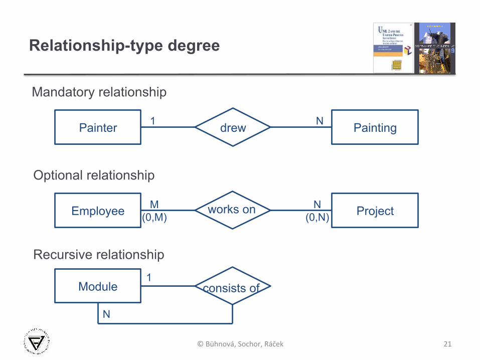
Relationship-type degree
21
Mandatory relationship
Optional relationship
Recursive relationship
© Bühnová, Sochor, Ráček
Painter drew Painting N 1
Employee works on Project N (0,N)
M (0,M)
Module consists of 1
N

Cardinality ratio
² Cardinality ratio of a relationship type describes the number of entities that can participate in the relationship.
² One to one 1:1 § Each lecturer has a unique office.
² One to many 1:N § A lecturer may tutor many students, but each student has just
one tutor.
² Many to many M:N § Each student takes several modules, and each module is taken
by several students.
22 © Bühnová, Sochor, Ráček
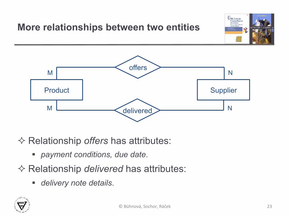
More relationships between two entities
² Relationship offers has attributes: § payment conditions, due date.
² Relationship delivered has attributes: § delivery note details.
23 © Bühnová, Sochor, Ráček
Product
offers
Supplier
N M
delivered N M
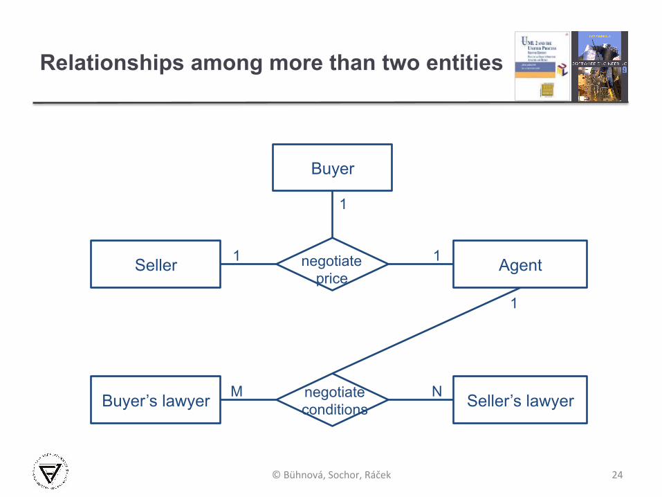
Relationships among more than two entities
24 © Bühnová, Sochor, Ráček
Seller negotiate price
Agent 1 1
Buyer’s lawyer negotiate conditions Seller’s lawyer N M
Buyer
1
1

Association entity
² The Contract exists just as a result of the relationship between the Customer and Product entity.
25
association entity
© Bühnová, Sochor, Ráček
Customer buys Product N M
Contract

Super-type and sub-type entities
² Extended ERDs model also inheritance, i.e. the relationship of specialization–generalization
26
super-type entity
sub-type entity
© Bühnová, Sochor, Ráček
Compact Van SUV
Car

ERD modeling in structured analysis
² Iterative development in structured analysis § Entities identification -> initial ERD § Attributes identification -> detailed ERD § Identification of missing and redundant entities
• Entities constituting of only one attribute (identifier) • Entity sets consisting of a single entity • Derived entities and relationships • Association entities • ERD-DFD consistency and completeness checking
² Modeled in parallel with DFD
27 © Bühnová, Sochor, Ráček

Removal of unneeded (redundant) entities
28
The Spouse entity is better suited as Employee’s attribute.
© Bühnová, Sochor, Ráček
Employee
married
Spouse
1
1
Employee
spouse

Removal of unneeded (redundant) entities
29 © Bühnová, Sochor, Ráček
Patient receives Medicament NM
Treatment
Patient 1
Treatment
receives
N medicament
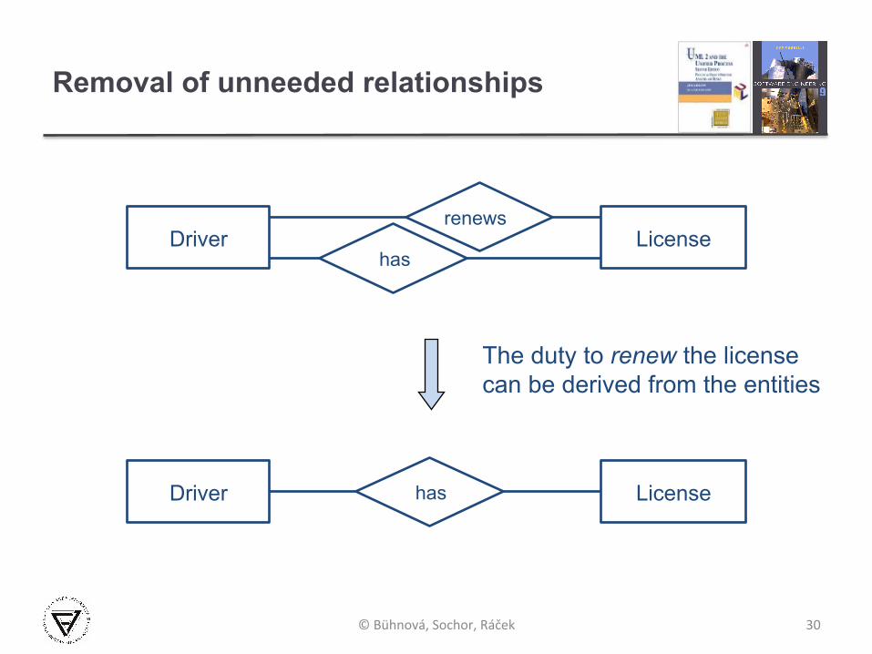
Removal of unneeded relationships
30
The duty to renew the license can be derived from the entities
© Bühnová, Sochor, Ráček
Driver has
License
Driver License
renews
has
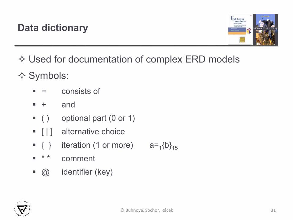
Data dictionary
² Used for documentation of complex ERD models
² Symbols: § = consists of § + and § ( ) optional part (0 or 1) § [ | ] alternative choice § { } iteration (1 or more) a=1{b}15
§ * * comment § @ identifier (key)
31 © Bühnová, Sochor, Ráček

Example – Order
² Order no. 2012-007-24
² Issue date: 23.4.2012 Delivery date: 30.4.2012
² Customer: no. 007 Dr. John Smith
² Goods: Number Name Pieces Price/piece P3876 Software engineering 6 135 H4681 UML2 and the UP 4 52 X6574 SA in practice 3 50
32 © Bühnová, Sochor, Ráček

Example – Order
² ORDER = @number + issue date + ( delivery date ) + customer number + customer name + { product number + product name + ordered pieces + ( product price per piece ) }
² customer name = ( title) + first name + surname
² title = [ Mr. | Mrs. | Miss. | Dr. | Prof. ]
² first name = { allowed symbol }
² allowed symbol = [ A - Z | a - z | ]
33 © Bühnová, Ráček, Sochor

Relational Database Design
Lecture 5/Part 3
34 © Bühnová, Sochor, Ráček

Crow's Foot notation
35
Entity
Entity
Entity
Entity
Exactly one occurrence
None or one occurrence
One or more occurrence
None or more occurrences
© Bühnová, Sochor, Ráček
relationship
relationship
relationship
relationship

ERD example – Transport
36 © Bühnová, Sochor, Ráček
Carrier
Driver Journey
License
Vehicle
employs
takes part in
is a holder of
is assigned to
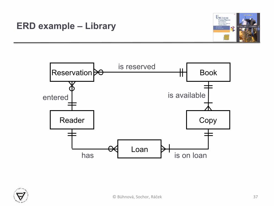
ERD example – Library
37 © Bühnová, Sochor, Ráček
Reservation Book
Copy
Loan
Reader
is reserved
is available
is on loan has
entered
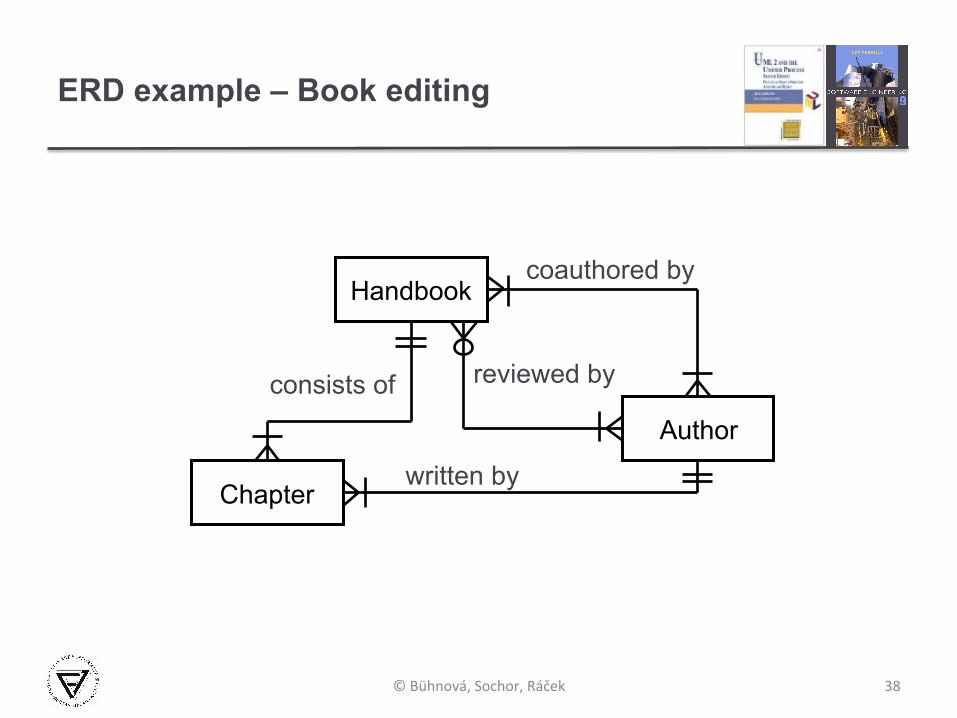
ERD example – Book editing
38 © Bühnová, Sochor, Ráček
Handbook
Chapter
Author
coauthored by
reviewed by consists of
written by

Relational database design based on ERDs
² Entity-relationship modeling is a first step towards database design.
Database design process: 1. Determine the purpose of the database. 2. Find and organize the information required - Create
ERD model of the system. Each entity type becomes a table, attribute becomes a column, entity becomes a row in the table. Handle relationships with attributes, association entities and M:N relationships.
39 © Bühnová, Sochor, Ráček
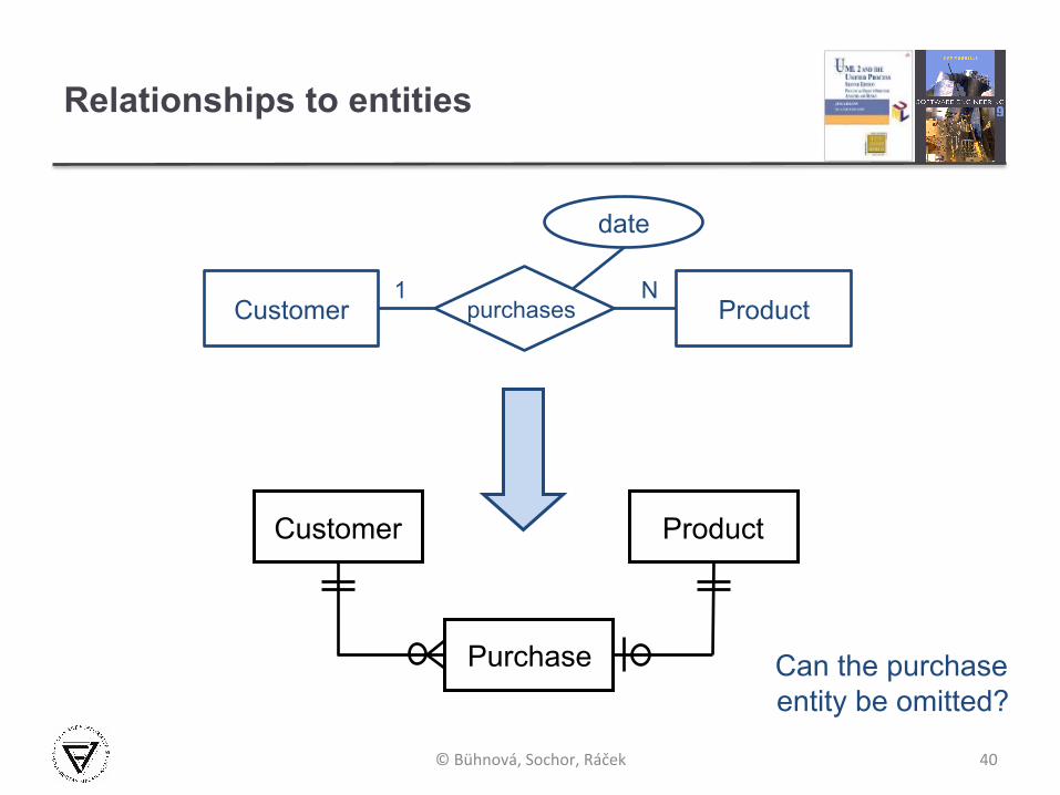
Relationships to entities
40 © Bühnová, Sochor, Ráček
Customer Product N1
Customer Product
Purchase
purchases
Can the purchase entity be omitted?
date
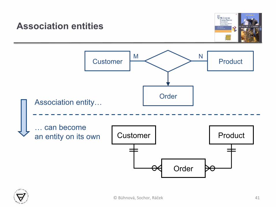
Association entities
41
… can become an entity on its own
Association entity…
© Bühnová, Sochor, Ráček
Customer Product NM
Order
Customer Product
Order
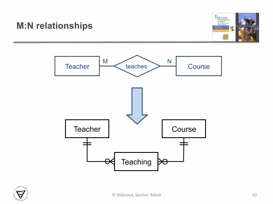
M:N relationships
42 © Bühnová, Sochor, Ráček
Teacher Course NM
Teacher Course
Teaching
teaches

Sub-types and super-types
43 © Bühnová, Sochor, Ráček
super-type entity
sub-type entity Compact Van SUV
Car
² Three options: § One big Car entity with all attributes § Three smaller Compact, SUV and Van entities § Four entities with relationship between sub-type and super-type entity
Database design process (continued)
3. Specify primary keys - Choose each table’s primary key. The primary key is a column that is used to uniquely identify each row. An example might be Product ID or Order ID.
4. Apply the normalization rules - Apply the data normalization rules to see if tables are structured correctly. Make adjustments to the tables.
5. Refine the design - Analyze the design for errors. Create tables and add a few records of sample data. Check if results come from the tables as expected. Make adjustments to the design, as needed.
44 © Bühnová, Sochor, Ráček

Entities and keys
² Superkey § A set of attributes that uniquely identifies each entity.
² Candidate key § A non-redundant superkey, i.e. all items of a candidate key are
necessary to identify an entity, no key attribute can be removed. § There can be more combinations of entity attributes that can be
used as candidate keys.
² Primary key § The selected candidate key, marked with # symbol.
² Foreign key § A set of attributes in one entity that uniquely identifies (i.e. is a
primary key in) another entity. 45 © Bühnová, Sochor, Ráček
Data normalization goals by E.F. Codd
² Minimize redundancy and dependency § Minimize redesign when extending database structure § Make the data model more informative to users
² Free the database of modification anomalies § Update anomaly – the same information expressed on multiple
rows → update resulting in logical inconsistencies. § Insertion anomaly – certain facts cannot be recorded, because
of their binding with another information into one record. § Deletion anomaly – deletion of data representing certain facts
necessitating deletion of unrelated data.
² Avoid bias towards any particular pattern of querying
46 © Bühnová, Sochor, Ráček
47
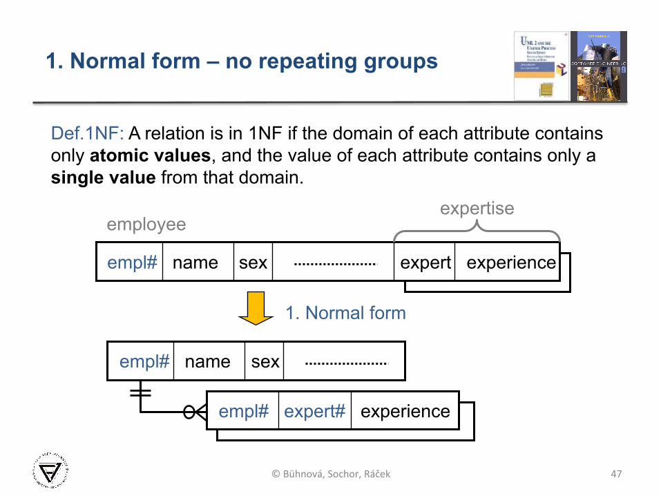
empl# name sex expert experience
employee expertise
empl# name sex
1. Normal form
empl# expert# experience
Def.1NF: A relation is in 1NF if the domain of each attribute contains only atomic values, and the value of each attribute contains only a single value from that domain.
© Bühnová, Sochor, Ráček
1. Normal form – no repeating groups
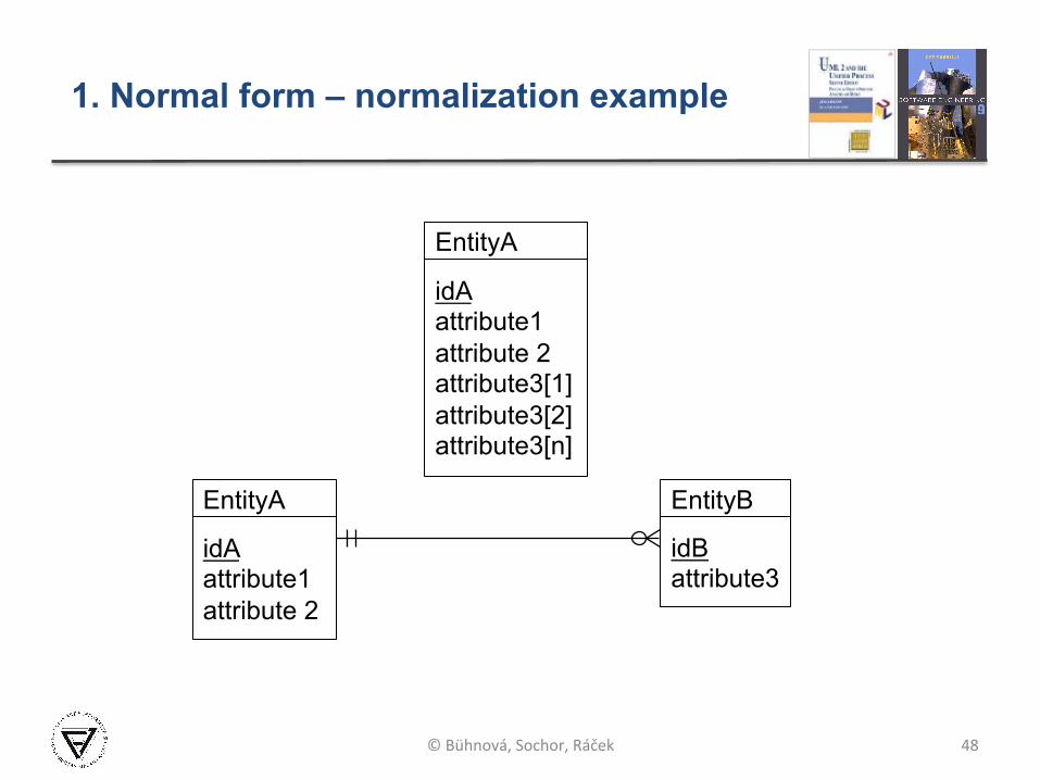
48
1. Normal form – normalization example
© Bühnová, Sochor, Ráček
EntityA EntityB
idA attribute1 attribute 2
idB attribute3
EntityA
idA attribute1 attribute 2 attribute3[1] attribute3[2] attribute3[n]

Functional dependency
² Functional dependency § In a given table, an attribute Y is said to have
a functional dependency on a set of attributes X if and only if each X value is associated with precisely one Y value.
² Trivial functional dependency § A trivial functional dependency is a functional
dependency of an attribute on a superset of itself.
² Full functional dependency § An attribute is fully functionally dependent on
a set of attributes X if it is: functionally dependent on X, and not functionally dependent on any proper subset of X.
49 © Bühnová, Sochor, Ráček
X1 X2 … Y
X1 X2
X1 X2 … Y
50
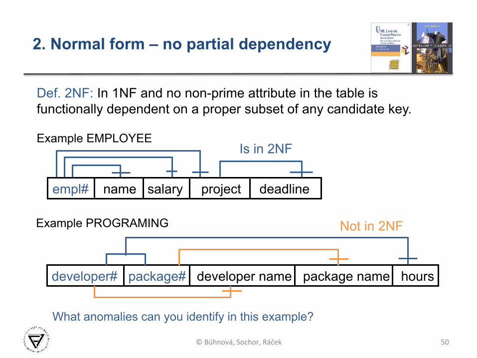
2. Normal form – no partial dependency
empl# name salary project deadline
developer# package# developer name package name hours
Example EMPLOYEE
Example PROGRAMING
Is in 2NF
Not in 2NF
Def. 2NF: In 1NF and no non-prime attribute in the table is functionally dependent on a proper subset of any candidate key.
© Bühnová, Sochor, Ráček
What anomalies can you identify in this example?
51
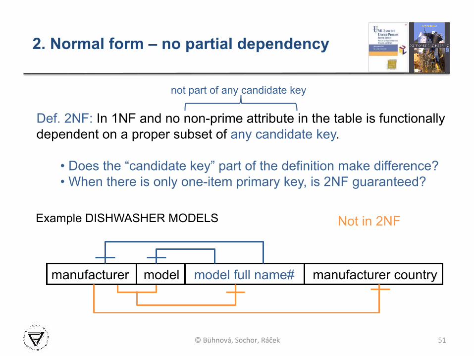
2. Normal form – no partial dependency
manufacturer model model full name# manufacturer country
Example DISHWASHER MODELS Not in 2NF
Def. 2NF: In 1NF and no non-prime attribute in the table is functionally dependent on a proper subset of any candidate key.
• Does the “candidate key” part of the definition make difference? • When there is only one-item primary key, is 2NF guaranteed?
© Bühnová, Sochor, Ráček
not part of any candidate key

52
2. Normal form – normalization example
course# student# student name student email registration date
student# student name student email
course# student# registration date
© Bühnová, Sochor, Ráček

53
3. Normal form – no transitive dependency
Def. 3NF: In 2NF and every non-prime attribute is non-transitively (i.e. only directly) dependent on every candidate key.
© Bühnová, Sochor, Ráček
What anomalies can you identify in this example?
empl# name salary project deadline
Example EMPLOYEE Not in 3NF
54
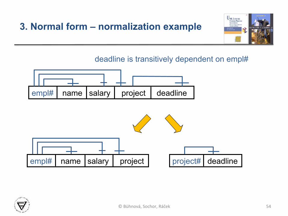
3. Normal form – normalization example
deadline is transitively dependent on empl#
© Bühnová, Sochor, Ráček
empl# name salary project deadline
empl# name salary project project# deadline
55
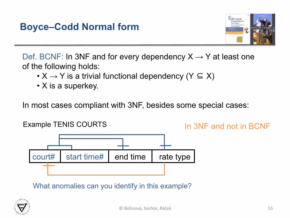
Boyce–Codd Normal form
court# start time# end time rate type
Example TENIS COURTS In 3NF and not in BCNF
Def. BCNF: In 3NF and for every dependency X → Y at least one of the following holds:
• X → Y is a trivial functional dependency (Y ⊆ X) • X is a superkey.
In most cases compliant with 3NF, besides some special cases:
© Bühnová, Sochor, Ráček
What anomalies can you identify in this example?
Normal forms overview
56
² 1NF: no repeating groups
² 2NF: no partial dependency
² 3NF: no transitive dependency
² BCNF: “Everything should be dependent on the key, the whole key, and nothing but the key” so help me Codd. [joke attributed to C.J.Date]
© Bühnová, Sochor, Ráček
ERD vs. UML Class Diagram
57
² Class diagrams § model both structural and behavior features of a system
(attribute and operations), § contain many different types of relationships (association,
aggregation, composition, dependency, generalization), and § are more likely to map into real-world objects.
² Entity relationship models § model only structural data view with a low variety of
relationships (simple relations and rarely generalization), and § are more likely to map into database tables (repetitive records). § They allow us to design primary and foreign entity keys, and
used to be normalized to simplify data manipulation.
© Bühnová, Sochor, Ráček
ERD vs. UML Class Diagram
58
² Although there can be one to one mapping between ERD and Class diagram, it is very common that § one class is mapped to more than one entity, or § more classes are mapped to a single entity.
² Furthermore, not all classes need to be persistent and hence reflected in the ERD model, which uses to be driven by the database design.
² Summary: § ERD is data-oriented and persistence-specific § Class diagram targets also operations and is persistence
independent
© Bühnová, Sochor, Ráček

Key points
² Structured analysis, and YMSA in particular, models systems from the perspectives of: § system interaction with its environment (CD), and § hierarchy of system processes and data flows (DFD).
² Data modeling, and ERD in particular, focuses on modeling entities, relationships and attributes of system data.
² Data normalization focuses on reducing redundancy and dependency in database design, and on avoiding bias towards a particular pattern of querying.
59 © Bühnová, Ráček, Sochor