Trilogy Manual Electrostatic Air Spray/HVLP Waterborne...
66
Trilogyt Manual Electrostatic Air Spray/HVLP Waterborne Spray Gun Customer Product Manual Part 1093558A Issued 6/09 NORDSON CORPORATION AMHERST, OHIO USA C APPROVED US FM For parts and technical support, call the Industrial Coating Systems Customer Support Center at (800) 433-9319 or contact your local Nordson representative. This document is subject to change without notice. Check http://emanuals.nordson.com for the latest version.
Transcript of Trilogy Manual Electrostatic Air Spray/HVLP Waterborne...

Trilogy� ManualElectrostatic Air Spray/HVLP
Waterborne Spray GunCustomer Product Manual
Part 1093558AIssued 6/09
NORDSON CORPORATION AMHERST, OHIO USA
CAPPROVED
USFM
For parts and technical support, call the Industrial CoatingSystems Customer Support Center at (800) 433-9319 or
contact your local Nordson representative.
This document is subject to change without notice.Check http://emanuals.nordson.com for the latest version.

Part 1093558A � 2009 Nordson Corporation
Contact UsNordson Corporation welcomes requests for information, comments, andinquiries about its products. General information about Nordson can befound on the Internet using the following address:http://www.nordson.com.Address all correspondence to:
Nordson CorporationAttn: Customer Service555 Jackson StreetAmherst, OH 44001
NoticeThis is a Nordson Corporation publication which is protected by copyright.Original copyright date 2009. No part of this document may bephotocopied, reproduced, or translated to another language without theprior written consent of Nordson Corporation. The information containedin this publication is subject to change without notice.
Trademarks
Kinetix, Nordson, and the Nordson logo are registered trademarks ofNordson Corporation.
Trilogy is a trademark of Nordson Corporation.
Kalrez and Viton are registered trademarks of E.I. DuPont de Nemoursand Company.
Loctite is a registered trademark of Loctite Corporation.
MagnaLube is a registered trademark of General Magnaplate Corporation.
Perlast is a registered trademark of Precision Polymer EngineeringLimited.
Velcro is a registered trademark of Velcro Industries B.V. LTD.

Table of Contents i
Part 1093558A� 2009 Nordson Corporation
Table of Contents
Safety 1-1. . . . . . . . . . . . . . . . . . . . . . . . . . . . . . . . . . . . . . . . . . . . . . . . . .Introduction 1-1. . . . . . . . . . . . . . . . . . . . . . . . . . . . . . . . . . . . . . . . . . . . .Qualified Personnel 1-1. . . . . . . . . . . . . . . . . . . . . . . . . . . . . . . . . . . . . .Intended Use 1-1. . . . . . . . . . . . . . . . . . . . . . . . . . . . . . . . . . . . . . . . . . .Regulations and Approvals 1-1. . . . . . . . . . . . . . . . . . . . . . . . . . . . . . .Personal Safety 1-2. . . . . . . . . . . . . . . . . . . . . . . . . . . . . . . . . . . . . . . . .
High-Pressure Fluids 1-3. . . . . . . . . . . . . . . . . . . . . . . . . . . . . . . . . .Fire Safety 1-4. . . . . . . . . . . . . . . . . . . . . . . . . . . . . . . . . . . . . . . . . . . . .
Halogenated Hydrocarbon Solvent Hazards 1-4. . . . . . . . . . . . . .Action in the Event of a Malfunction 1-5. . . . . . . . . . . . . . . . . . . . . . . .Disposal 1-5. . . . . . . . . . . . . . . . . . . . . . . . . . . . . . . . . . . . . . . . . . . . . . .Safety Label 1-5. . . . . . . . . . . . . . . . . . . . . . . . . . . . . . . . . . . . . . . . . . . .
Description 2-1. . . . . . . . . . . . . . . . . . . . . . . . . . . . . . . . . . . . . . . . . . . . .Introduction 2-1. . . . . . . . . . . . . . . . . . . . . . . . . . . . . . . . . . . . . . . . . . . . .
Spray Gun Features 2-2. . . . . . . . . . . . . . . . . . . . . . . . . . . . . . . . . . .Spray Technology 2-2. . . . . . . . . . . . . . . . . . . . . . . . . . . . . . . . . . . . .Options 2-2. . . . . . . . . . . . . . . . . . . . . . . . . . . . . . . . . . . . . . . . . . . . . .Coating Materials 2-2. . . . . . . . . . . . . . . . . . . . . . . . . . . . . . . . . . . . . .
Theory of Operation 2-3. . . . . . . . . . . . . . . . . . . . . . . . . . . . . . . . . . . . .Trigger Lock 2-3. . . . . . . . . . . . . . . . . . . . . . . . . . . . . . . . . . . . . . . . . .Electrostatic Charge 2-3. . . . . . . . . . . . . . . . . . . . . . . . . . . . . . . . . . .Fluid Flow 2-3. . . . . . . . . . . . . . . . . . . . . . . . . . . . . . . . . . . . . . . . . . . .Air Flow 2-5. . . . . . . . . . . . . . . . . . . . . . . . . . . . . . . . . . . . . . . . . . . . . .
Specifications 2-5. . . . . . . . . . . . . . . . . . . . . . . . . . . . . . . . . . . . . . . . . . .Dimensions 2-5. . . . . . . . . . . . . . . . . . . . . . . . . . . . . . . . . . . . . . . . . . .Weight 2-5. . . . . . . . . . . . . . . . . . . . . . . . . . . . . . . . . . . . . . . . . . . . . . .Operating Pressures 2-5. . . . . . . . . . . . . . . . . . . . . . . . . . . . . . . . . . .Electrostatics 2-6. . . . . . . . . . . . . . . . . . . . . . . . . . . . . . . . . . . . . . . . .Spray Gun Fitting Sizes 2-6. . . . . . . . . . . . . . . . . . . . . . . . . . . . . . . .Fluid Hose 2-6. . . . . . . . . . . . . . . . . . . . . . . . . . . . . . . . . . . . . . . . . . .Optional Air Hoses 2-6. . . . . . . . . . . . . . . . . . . . . . . . . . . . . . . . . . . . .Approvals 2-6. . . . . . . . . . . . . . . . . . . . . . . . . . . . . . . . . . . . . . . . . . . .
Installation 3-1. . . . . . . . . . . . . . . . . . . . . . . . . . . . . . . . . . . . . . . . . . . . .Preparation 3-1. . . . . . . . . . . . . . . . . . . . . . . . . . . . . . . . . . . . . . . . . . . . .Typical 60 kV Waterborne System 3-2. . . . . . . . . . . . . . . . . . . . . . . . . .Air and Fluid Hose Connections 3-3. . . . . . . . . . . . . . . . . . . . . . . . . . . .
Air Hose Connection 3-3. . . . . . . . . . . . . . . . . . . . . . . . . . . . . . . . . . .Fluid Hose Connection 3-3. . . . . . . . . . . . . . . . . . . . . . . . . . . . . . . . .
Securing the Air and Fluid Hoses 3-3. . . . . . . . . . . . . . . . . . . . . . . . . .Fluid Tip and Air Cap Installation 3-4. . . . . . . . . . . . . . . . . . . . . . . . . .

Table of Contentsii
Part 1093558A � 2009 Nordson Corporation
Operation 4-1. . . . . . . . . . . . . . . . . . . . . . . . . . . . . . . . . . . . . . . . . . . . . .Introduction 4-1. . . . . . . . . . . . . . . . . . . . . . . . . . . . . . . . . . . . . . . . . . . . .System Startup 4-2. . . . . . . . . . . . . . . . . . . . . . . . . . . . . . . . . . . . . . . . . .Spray Adjustments 4-3. . . . . . . . . . . . . . . . . . . . . . . . . . . . . . . . . . . . . .
Fluid Pressure and Flow Rate Adjustments 4-3. . . . . . . . . . . . . . .Spray Pattern and Atomization Adjustments 4-3. . . . . . . . . . . . . .Fluid Tips and Air Caps 4-4. . . . . . . . . . . . . . . . . . . . . . . . . . . . . . . . .
Shutdown 4-4. . . . . . . . . . . . . . . . . . . . . . . . . . . . . . . . . . . . . . . . . . . . . . .Short-Term Shutdown 4-5. . . . . . . . . . . . . . . . . . . . . . . . . . . . . . . . . .Long-Term Shutdown 4-5. . . . . . . . . . . . . . . . . . . . . . . . . . . . . . . . . .Multi-Component Coatings 4-5. . . . . . . . . . . . . . . . . . . . . . . . . . . . . .
Needle Travel Adjustment 4-5. . . . . . . . . . . . . . . . . . . . . . . . . . . . . . . .HVLP Performance Testing 4-6. . . . . . . . . . . . . . . . . . . . . . . . . . . . . . . .
HVLP Compliance Test 4-6. . . . . . . . . . . . . . . . . . . . . . . . . . . . . . . . .
Maintenance 5-1. . . . . . . . . . . . . . . . . . . . . . . . . . . . . . . . . . . . . . . . . . .Introduction 5-1. . . . . . . . . . . . . . . . . . . . . . . . . . . . . . . . . . . . . . . . . . . . .Daily 5-1. . . . . . . . . . . . . . . . . . . . . . . . . . . . . . . . . . . . . . . . . . . . . . . . . . .Periodically 5-2. . . . . . . . . . . . . . . . . . . . . . . . . . . . . . . . . . . . . . . . . . . . .
System Flushing 5-3. . . . . . . . . . . . . . . . . . . . . . . . . . . . . . . . . . . . . .Spray Gun Cleaning 5-3. . . . . . . . . . . . . . . . . . . . . . . . . . . . . . . . . . .
Routine Cleaning 5-3. . . . . . . . . . . . . . . . . . . . . . . . . . . . . . . . . . .Extensive Cleaning 5-4. . . . . . . . . . . . . . . . . . . . . . . . . . . . . . . . . .
Troubleshooting 6-1. . . . . . . . . . . . . . . . . . . . . . . . . . . . . . . . . . . . . . . .Introduction 6-1. . . . . . . . . . . . . . . . . . . . . . . . . . . . . . . . . . . . . . . . . . . . .Common Problems 6-2. . . . . . . . . . . . . . . . . . . . . . . . . . . . . . . . . . . . . . .Spray Pattern/Film Build Troubleshooting 6-4. . . . . . . . . . . . . . . . . . .Electrostatic Troubleshooting 6-5. . . . . . . . . . . . . . . . . . . . . . . . . . . . . .
Repair 7-1. . . . . . . . . . . . . . . . . . . . . . . . . . . . . . . . . . . . . . . . . . . . . . . . .Tools/Supplies Required 7-2. . . . . . . . . . . . . . . . . . . . . . . . . . . . . . . . . .Air Cap, Fluid Tip, and Needle Replacement 7-3. . . . . . . . . . . . . . . .Trigger Lock Replacement 7-4. . . . . . . . . . . . . . . . . . . . . . . . . . . . . . . .Repair Preparation 7-4. . . . . . . . . . . . . . . . . . . . . . . . . . . . . . . . . . . . . .Packing Cartridge Replacement 7-5. . . . . . . . . . . . . . . . . . . . . . . . . . .
Removing the Extension 7-5. . . . . . . . . . . . . . . . . . . . . . . . . . . . . . .Removing the Packing Cartridge 7-6. . . . . . . . . . . . . . . . . . . . . . . .Needle Travel Adjustment 7-7. . . . . . . . . . . . . . . . . . . . . . . . . . . . . .Packing Cartridge Installation 7-7. . . . . . . . . . . . . . . . . . . . . . . . . . .Extension Installation 7-8. . . . . . . . . . . . . . . . . . . . . . . . . . . . . . . . . .
Air Valve Repair 7-9. . . . . . . . . . . . . . . . . . . . . . . . . . . . . . . . . . . . . . . . .Cover Removal 7-9. . . . . . . . . . . . . . . . . . . . . . . . . . . . . . . . . . . . . . .Air Valve Repair 7-9. . . . . . . . . . . . . . . . . . . . . . . . . . . . . . . . . . . . . .Cover Installation 7-11. . . . . . . . . . . . . . . . . . . . . . . . . . . . . . . . . . . . .
Horn Air Valve Repair 7-11. . . . . . . . . . . . . . . . . . . . . . . . . . . . . . . . . . . .Fluid Hose Replacement 7-12. . . . . . . . . . . . . . . . . . . . . . . . . . . . . . . . .Service Notes 7-14. . . . . . . . . . . . . . . . . . . . . . . . . . . . . . . . . . . . . . . . . . .
Table of Contents iii
Part 1093558A� 2009 Nordson Corporation
Parts 8-1. . . . . . . . . . . . . . . . . . . . . . . . . . . . . . . . . . . . . . . . . . . . . . . . . . .Introduction 8-1. . . . . . . . . . . . . . . . . . . . . . . . . . . . . . . . . . . . . . . . . . . . .Spray Gun Parts 8-1. . . . . . . . . . . . . . . . . . . . . . . . . . . . . . . . . . . . . . . . .Repair Kits 8-4. . . . . . . . . . . . . . . . . . . . . . . . . . . . . . . . . . . . . . . . . . . . . .
Air Seal Kit 8-4. . . . . . . . . . . . . . . . . . . . . . . . . . . . . . . . . . . . . . . . . . .Air Valve Kit 8-4. . . . . . . . . . . . . . . . . . . . . . . . . . . . . . . . . . . . . . . . . .Trigger Lock Kit 8-4. . . . . . . . . . . . . . . . . . . . . . . . . . . . . . . . . . . . . . .Ferrule Kit 8-4. . . . . . . . . . . . . . . . . . . . . . . . . . . . . . . . . . . . . . . . . . . .
Recommended Spare Parts 8-5. . . . . . . . . . . . . . . . . . . . . . . . . . . . . . .Options 8-5. . . . . . . . . . . . . . . . . . . . . . . . . . . . . . . . . . . . . . . . . . . . . . . .
Air Caps and Fluid Tips 8-5. . . . . . . . . . . . . . . . . . . . . . . . . . . . . . . .Adhesives, Sealants, and Lubricants 8-5. . . . . . . . . . . . . . . . . . . . .Cable Extension 8-6. . . . . . . . . . . . . . . . . . . . . . . . . . . . . . . . . . . . . .Fluid and Air Hoses and Fittings 8-6. . . . . . . . . . . . . . . . . . . . . . . . .HVLP Compliance Kit 8-6. . . . . . . . . . . . . . . . . . . . . . . . . . . . . . . . . .

Table of Contentsiv
Part 1093558A � 2009 Nordson Corporation

Safety 1-1
Part 1093558A� 2009 Nordson Corporation
Section 1Safety
Introduction Read and follow these safety instructions. Task- and equipment-specificwarnings, cautions, and instructions are included in equipmentdocumentation where appropriate.
Make sure all equipment documentation, including these instructions, isaccessible to persons operating or servicing equipment.
Qualified Personnel Equipment owners are responsible for making sure that Nordson equipmentis installed, operated, and serviced by qualified personnel. Qualifiedpersonnel are those employees or contractors who are trained to safelyperform their assigned tasks. They are familiar with all relevant safety rulesand regulations and are physically capable of performing their assignedtasks.
Intended Use Use of Nordson equipment in ways other than those described in thedocumentation supplied with the equipment may result in injury to personsor damage to property.
Some examples of unintended use of equipment include
� using incompatible materials
� making unauthorized modifications
� removing or bypassing safety guards or interlocks
� using incompatible or damaged parts
� using unapproved auxiliary equipment
� operating equipment in excess of maximum ratings
Regulations and Approvals Make sure all equipment is rated and approved for the environment in whichit is used. Any approvals obtained for Nordson equipment will be voided ifinstructions for installation, operation, and service are not followed.
Safety1-2
Part 1093558A � 2009 Nordson Corporation
Personal Safety To prevent injury follow these instructions.
� Do not operate or service equipment unless you are qualified.
� Do not operate equipment unless safety guards, doors, or covers areintact and automatic interlocks are operating properly. Do not bypass ordisarm any safety devices.
� Keep clear of moving equipment. Before adjusting or servicing movingequipment, shut off the power supply and wait until the equipmentcomes to a complete stop. Lock out power and secure the equipment toprevent unexpected movement.
� Relieve (bleed off) hydraulic and pneumatic pressure before adjusting orservicing pressurized systems or components. Disconnect, lock out,and tag switches before servicing electrical equipment.
� While operating manual spray guns, make sure you are grounded.Wear electrically conductive gloves or a grounding strap connected tothe gun handle or other true earth ground. Do not wear or carry metallicobjects such as jewelry or tools.
� If you receive even a slight electrical shock, shut down all electrical orelectrostatic equipment immediately. Do not restart the equipment untilthe problem has been identified and corrected.
� Obtain and read Material Safety Data Sheets (MSDS) for all materialsused. Follow the manufacturer’s instructions for safe handling and useof materials, and use recommended personal protection devices.
� Make sure the spray area is adequately ventilated.
� To prevent injury, be aware of less-obvious dangers in the workplacethat often cannot be completely eliminated, such as hot surfaces, sharpedges, energized electrical circuits, and moving parts that cannot beenclosed or otherwise guarded for practical reasons.

Safety 1-3
Part 1093558A� 2009 Nordson Corporation
High-Pressure Fluids High-pressure fluids, unless they are safely contained, are extremelyhazardous. Always relieve fluid pressure before adjusting or servicing highpressure equipment. A jet of high-pressure fluid can cut like a knife andcause serious bodily injury, amputation, or death. Fluids penetrating theskin can also cause toxic poisoning.
If you suffer a fluid injection injury, seek medical care immediately. Ifpossible, provide a copy of the MSDS for the injected fluid to the health careprovider.
The National Spray Equipment Manufacturers Association has created awallet card that you should carry when you are operating high-pressurespray equipment. These cards are supplied with your equipment. Thefollowing is the text of this card:
WARNING: Any injury caused by high pressure liquid can be serious. Ifyou are injured or even suspect an injury:
� Go to an emergency room immediately.
� Tell the doctor that you suspect an injection injury.
� Show him this card
� Tell him what kind of material you were spraying
MEDICAL ALERT—AIRLESS SPRAY WOUNDS: NOTE TO PHYSICIAN
Injection in the skin is a serious traumatic injury. It is important to treat theinjury surgically as soon as possible. Do not delay treatment to researchtoxicity. Toxicity is a concern with some exotic coatings injected directly intothe bloodstream.
Consultation with a plastic surgeon or a reconstructive hand surgeon maybe advisable.
The seriousness of the wound depends on where the injury is on the body,whether the substance hit something on its way in and deflected causingmore damage, and many other variables including skin microflora residingin the paint or gun which are blasted into the wound. If the injected paintcontains acrylic latex and titanium dioxide that damage the tissue’sresistance to infection, bacterial growth will flourish. The treatment thatdoctors recommend for an injection injury to the hand includes immediatedecompression of the closed vascular compartments of the hand to releasethe underlying tissue distended by the injected paint, judicious wounddebridement, and immediate antibiotic treatment.

Safety1-4
Part 1093558A � 2009 Nordson Corporation
Fire Safety To avoid a fire or explosion, follow these instructions.
� Ground all conductive equipment. Use only grounded air and fluidhoses. Check equipment and workpiece grounding devices regularly.Resistance to ground must not exceed one megohm.
� Shut down all equipment immediately if you notice static sparking orarcing. Do not restart the equipment until the cause has been identifiedand corrected.
� Do not smoke, weld, grind, or use open flames where flammablematerials are being used or stored.
� Do not heat materials to temperatures above those recommended bythe manufacturer. Make sure heat monitoring and limiting devices areworking properly.
� Provide adequate ventilation to prevent dangerous concentrations ofvolatile particles or vapors. Refer to local codes or your material MSDSfor guidance.
� Do not disconnect live electrical circuits when working with flammablematerials. Shut off power at a disconnect switch first to preventsparking.
� Know where emergency stop buttons, shutoff valves, and fireextinguishers are located. If a fire starts in a spray booth, immediatelyshut off the spray system and exhaust fans.
� Shut off electrostatic power and ground the charging system beforeadjusting, cleaning, or repairing electrostatic equipment.
� Clean, maintain, test, and repair equipment according to the instructionsin your equipment documentation.
� Use only replacement parts that are designed for use with originalequipment. Contact your Nordson representative for parts informationand advice.
Halogenated Hydrocarbon Solvent Hazards Do not use halogenated hydrocarbon solvents in a pressurized system thatcontains aluminum components. Under pressure, these solvents can reactwith aluminum and explode, causing injury, death, or property damage.Halogenated hydrocarbon solvents contain one or more of the followingelements:
Element Symbol Prefix
Fluorine F “Fluoro-”
Chlorine Cl “Chloro-”
Bromine Br “Bromo-”
Iodine I “Iodo-”
Check your material MSDS or contact your material supplier for moreinformation. If you must use halogenated hydrocarbon solvents, contactyour Nordson representative for information about compatible Nordsoncomponents.

Safety 1-5
Part 1093558A� 2009 Nordson Corporation
Action in the Event of a Malfunction If a system or any equipment in a system malfunctions, shut off the systemimmediately and perform the following steps:
� Disconnect and lock out system electrical power. Close hydraulic andpneumatic shutoff valves and relieve pressures.
� Identify the reason for the malfunction and correct it before restarting thesystem.
Disposal Dispose of equipment and materials used in operation and servicingaccording to local codes.
Safety Label Table 1-1 contains the text of the safety label on this equipment. The safetylabel is provided to help you operate and maintain your equipment safely.
Table 1-1 Safety Label
Symbol Description
WARNING: Allow only qualified personnel to use this equipment.Observe and follow all safety instructions for this equipment.
WARNING: Risk of explosion or fire. Fire, open flames, andsmoking prohibited.
WARNING: Do not point the spray gun at any part of your body orat anyone else. Do not operate the fluid delivery system if anycomponent is leaking. Failure to observe this warning could resultin an injection injury.
WARNING: Risk of electrical shock. Disconnect and lockout inputpower to equipment before servicing. Failure to observe thiswarning may result in personal injury or death.

Safety1-6
Part 1093558A � 2009 Nordson Corporation

Description 2-1
Part 1093558A� 2009 Nordson Corporation
Section 2Description
Introduction See Figure 2-1.
The Trilogy manual electrostatic air spray/HVLP waterborne spray gun isdesigned to apply waterborne coating materials. It is used with the NordsonIso-Flo system, which electrostatically charges waterborne coatings anddelivers them to the spray gun while electrically isolating the chargedcoating from the coating supply. The electrostatic voltage is provided by aseparate EPS-6 electrostatic power supply.
The spray gun is non-circulating and can be used with heated and unheatednon-circulating spray systems. For systems that require circulation, acirculation fitting can be coupled to the inlet fluid fitting. Refer to the Partssection for ordering information.
HVLP and air spray systems use low-pressure fluid sources, such aspressure pots, diaphragm pumps, or low-ratio piston pumps. They arecommonly used to apply low to medium viscosity fluids to products requiringa high-quality finish.
2
1 4
3
5
Figure 2-1 Trilogy Air Spray/HVLP Manual Electrostatic Waterborne Spray Gun
1. Fluid flow adjust knob2. Trigger lock3. Fluid hose
4. Air fitting 1/4 in. NPS5. Horn air adjust knob

Description2-2
Part 1093558A � 2009 Nordson Corporation
Spray Gun FeaturesThe Trilogy spray gun features:
� adjustable horn air pressure and fluid flow rate
� large air passages for higher air energy
� bellows-type packing cartridge
� 25 ft, 1/4-in. ID fluid hose
Spray TechnologyThe fluid tip and air cap you choose to use determines the spray guntechnology: air spray or HVLP.
HVLP technology creates a soft spray with high transfer efficiency,reducing emissions of volatile organic compounds (VOCs). HVLP sprayguns use high volumes of very low pressure pattern control (horn) andatomizing air (less than 0.69 bar (10 psi)). The high volume of patterncontrol air provides sufficient energy to shape the pattern of sprayed fluids.The low atomizing air pressure reduces fluid bounceback and overspray,which improves transfer efficiency.
HVLP atomization is typically coarser than air spray when used withhigh-viscosity fluids and high flow rates.
Air spray technology atomizes material at higher air pressures and lowerair flows than HVLP spray guns. Air spray guns produce a very fine,atomized mist. This makes them useful for extremely fine finishing work.
OptionsOptions include a variety of fluid tips and air caps, air hoses, and a 50-ftcable extension. HVLP compliance kits are available for each HVLP aircap. Refer to Options in the Parts section.
Coating MaterialsThe spray guns are compatible with a wide variety of waterborne coatingmaterials.
NOTE: The seals installed in the spray gun are compatible with mostcoatings. If the coating material you use damages the seals, contact yourNordson Corporation representative for compatible replacements.

Description 2-3
Part 1093558A� 2009 Nordson Corporation
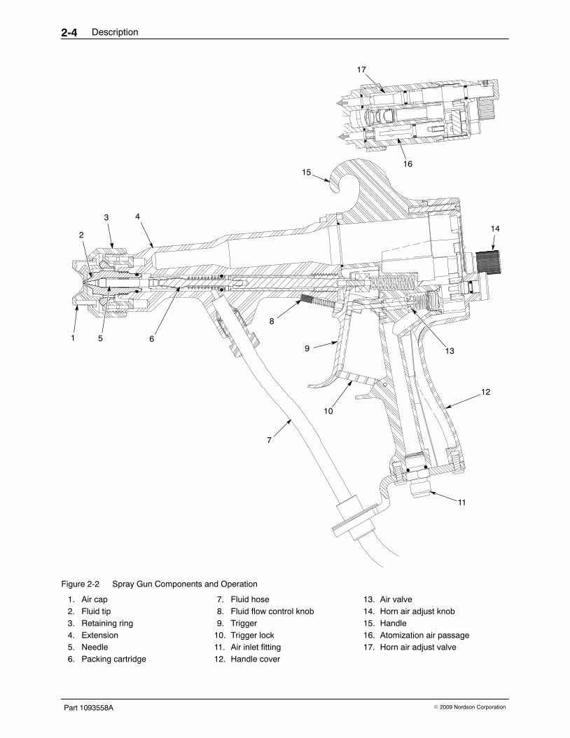
Theory of Operation See Figure 2-2.
Trigger Lock The gun includes a trigger lock (10) to prevent accidental triggering of thespray gun and possible injection injuries.
Electrostatic ChargeA manual Iso-Flo voltage block system delivers electrostatically chargedand pressurized coating material to the spray gun on demand andelectrically isolates the spray gun and fluid path from the grounded coatingmaterial supply. The electrostatic voltage is generated by an EPS-6 60 kVelectrostatic power supply.
The charged coating material flows through a special fluid supply hose (7)to the spray gun. As the charged coating material is sprayed it is attractedto the grounded workpiece.
Fluid FlowFluid enters the spray gun extension (4) and flows past the packingcartridge (6) to the fluid tip (2). When the trigger (9) is pulled it pulls theneedle (5) off its seat in the fluid tip, allowing fluid to flow out of the gun.The fluid flow control knob (8) controls how far the needle is pulled off theseat, which determines fluid flow through the fluid tip.
The packing cartridge (6) prevents fluid from flowing past it into thehandle (15). The fluid flow is dead-ended at the spray gun when the triggeris released.
Description2-4
Part 1093558A � 2009 Nordson Corporation
12
4
9
7
11
10
15
8
14
1
17
16
13
2
5 6
3
Figure 2-2 Spray Gun Components and Operation
1. Air cap2. Fluid tip3. Retaining ring4. Extension5. Needle6. Packing cartridge
7. Fluid hose8. Fluid flow control knob9. Trigger
10. Trigger lock11. Air inlet fitting12. Handle cover
13. Air valve14. Horn air adjust knob15. Handle16. Atomization air passage17. Horn air adjust valve

Description 2-5
Part 1093558A� 2009 Nordson Corporation
Air FlowCompressed air enters the spray gun through an inlet fitting (11) in the spraygun handle (15).
Pulling the trigger opens the air valve (13), allowing air to flow through theatomization (16) and horn air passages to the air cap. The air flow triggersa pressure switch in the Iso-Flo system, which turns on the electrostaticpower supply and charges the coating material.
Atomization air flows through the handle and extension to the air cap whenthe spray gun is triggered. The atomization air atomizes the coatingmaterial as it exits the nozzle. To control atomization, adjust the airpressure regulator that supplies the spray gun.
Horn air flows past the horn air valve (17) to the air cap (1) and shapes thespray pattern. The horn air flow is controlled by adjusting the valve openingwith the knob (14).
Specifications
DimensionsDimensions Metric (cm) English (in.)
Height 22.28 8.77
Length 30.48 12.00
Width 5.58 2.20
NOTE: The spray gun dimensions include the fluid and air fittings.
WeightWeight Metric (g) English (oz)
Airspray/HVLP spray gun 711 25.1
NOTE: The spray gun weight includes the fluid and air fittings.
Operating PressuresOperating Pressures Metric English
Maximum air input pressure 6.9 bar 100 psi
Maximum fluid input pressure 6.9 bar 100 psi
Maximum fluid temperature 82 �C 180 �F
NOTE: Supply air must be particulate free (5 microns maximum) and oilfree. Use coalescing-type air filters.

Description2-6
Part 1093558A � 2009 Nordson Corporation
ElectrostaticsMaximum voltage: 60 kVMaximum output rating current: 150 microamps
Spray Gun Fitting SizesSpray Gun Standard Fitting Sizes
Air fitting 1/4-in. NPS, Male
Fluid fitting 3/8-in. NPS, Male
Fluid Hose Hose Length ID Fittings
7.62 meter (25 ft)
6.35 mm(1/4 in.)
1/4 in. NPSfemale fitting
Optional Air HosesLength ID Fittings
9.14, 15.24, 30.48 meter(30, 50, 100 ft.)
9.25 mm(3/8 in.)
1/4 in. NPSfemale fittings
ApprovalsThis spray gun has met the requirements for FM and CE approval.

Installation 3-1
Part 1093558A� 2009 Nordson Corporation
Section 3Installation
WARNING: Allow only qualified personnel to perform the following tasks.Follow the safety instructions in this document and all other relateddocumentation.
Preparation
CAUTION: Do not overtighten parts. Failure to observe this caution willresult in equipment damage.
Fluid tips, air caps, and hoses are not shipped with the spray gun. Youmust order them separately, based on your application. If you order a HVLPair cap, order the appropriate compliance kit also. You will need onecompliance kit for each air cap size you use.
Compliance caps are used to verify compliance of non-electrostatic HVLPsystems. Electrostatic guns are by themselves compliant spraytechnologies so it is not necessary to verify air cap compliance. Instead,you may want to use a compliance kit to make sure the air cap pressure isat optimum level.
Before installation,
� remove the spray gun, brushes, and tool kit from the box.
� make sure you have the appropriate fluid tip and air cap for yourapplication.
� make sure you have air and fluid hoses of the correct length, ID, andmaterials.
WARNING: Risk of fire and/or electrical shock if the spray gun and systemcomponents are not properly grounded.
� make sure the system is properly grounded.
NOTE: Inadequately grounded parts will adversely affect transfer efficiencyand coating quality.

Installation3-2
Part 1093558A � 2009 Nordson Corporation
Typical 60 kV Waterborne SystemFigure 3-1 shows the components of a typical electrostatic waterbornesystem.
NOTE: Some components shown are optional. Make sure your systemcontains self-relieving shutoff valves for both air and fluid supply.
13
1 4
5
67
9
2
11
3
Fluid
Air
14
8
15
12
10
Figure 3-1 Typical Manual 60 kV Air Spray/HVLP System
1. Iso-Flo HD voltage block system2. Fluid pressure regulator/gauge3. Fluid supply line4. System air regulator5. System air filter
6. Air drop drain valve7. EPS-6 electrostatic power supply8. Air line from air flow sensor9. Pressure switch
10. Atomizing air pressure regulator
11. Fluid hose12. Fluid hose ground13. Air hose14. Spray gun15. Electrostatic cable

Installation 3-3
Part 1093558A� 2009 Nordson Corporation
Air and Fluid Hose ConnectionsAir Hose Connection
The air hose supplying air to the spray gun should be a grounding typehose. Limit the number of restrictions in the air supply lines and hose toprovide maximum air flow.
For optimum HVLP performance, 3/8-in. ID hose is recommended, no longerthan 9.14 m (30 ft).
1. Clean the air hose fittings with a clean, dry cloth.
2. Connect the air hose to the air OUT fitting on the gun control unit to the1/4-in. NPSM fitting in the spray gun handle.
Fluid Hose ConnectionThe spray gun is shipped with a 7.62-meter (25-ft) fluid hose installed on thegun. The hose is equipped with a 3/8-in. NPT stainless steel fitting forconnection to a fluid delivery system, and a ground wire with a ring-tongterminal.
Connect the stainless steel hose fitting to the PAINT OUT fitting on theIso-Flo cabinet or to the fluid outlet of an alternate fluid delivery system.
Connect the ring-tong terminal on the hose ground wire to the ground studon the side of the Iso-Flo cabinet or a true earth ground.
Securing the Air and Fluid HosesBundle together the fluid and air hose where practical. Do the following toprevent wear and damage:
� Bundle the hoses together with hook and loop tape, spiral-cut tubing, orsimilar devices. If you secure the hoses to a stationary object at anypoint between the fluid delivery system and the gun, make sure thehoses can flex without strain.
� Do not tie the hoses to machine members in areas where they mustmove or stretch.
� Do not kink the hoses.
� Do not allow the hoses to become abraded by sharp corners such asbooth edges.
� Do not walk on the hoses or run over them with heavy objects.
� If desired, cover the spray gun body, hoses, and other equipment in thespray area with a grounded, conductive wrapping to keep them clean.

Installation3-4
Part 1093558A � 2009 Nordson Corporation
Fluid Tip and Air Cap Installation See Figure 3-2. Use this procedure to install a fluid tip and air cap on a newspray gun. To remove and replace the fluid tip and air cap, refer toSection 7 Repair.
CAUTION: To prevent damage to the needle or fluid tip seat, pull and holdthe trigger while removing or installing the fluid tip.
1. Unscrew the retaining ring (6).
2. Lubricate the fluid tip (3) O-ring (2) with O-ring grease.
3. Pull the trigger to retract the needle (1).
4. Thread the fluid tip into the extension and tighten it snugly with thecombination tool. Do not overtighten.
CAUTION: Tightening the fluid tip beyond snug does not prevent oreliminate fluid leaks. If coating material leaks around the fluid tip replacethe O-ring.
5. Install the air cap (4) into the retaining ring and thread the retaining ringonto the extension. Make sure the air cap is centered on the fluid tip.Hold the air cap in the desired position and tighten the retaining ring untilit is snug. Do not overtighten the retaining ring.
NOTE: 991 and 992 air spray air caps are shipped permanently installedinto retaining rings. These retaining rings cannot be used with the 985−988air caps, which use the standard retaining ring shipped with the spray gun.
3
54
2 1
Figure 3-2 Fluid Tip and Air Cap Installation
1. Needle2. Fluid tip O-ring3. Fluid tip
4. Air cap5. Retaining ring

Operation 4-1
Part 1093558A� 2009 Nordson Corporation
Section 4Operation
WARNING: Allow only qualified personnel to perform the following tasks.Follow the safety instructions in this document and all other relateddocumentation.
Introduction
WARNING: This equipment can be dangerous unless it is used inaccordance with the rules laid down in this manual.
WARNING: Do not exceed the maximum fluid pressure rating of6.9 bar (100 psi). Failure to follow this warning may result in personal injuryor death.
WARNING: Engage the trigger lock whenever you are not spraying toprevent accidental triggering of the spray gun and possible injection injuries.Failure to observe this warning may result in injury.
WARNING: The Trilogy spray gun, EPS6 power supply, Nordsonhigh-voltage cable, Nordson waterborne hose, and the Iso-Flo unit areconsidered a system. The stored energy of the system could bedangerously increased by any changes. Nordson Corporation should becontacted before any changes are made.
WARNING: Do not add any joints or fittings to a waterborne fluid hoseintended for use with spraying charged fluid. If the hose becomes damagedreplace the entire hose assembly with the appropriate Nordson hose ofidentical length.
WARNING: Ground all electrically conductive equipment. Ungroundedconductive equipment can store a static charge, which could ignite a fire orcause an explosion if a hot spark is discharged. Wear shoes withconductive soles or use grounding straps to maintain a connection toground when working with or around electrostatic equipment.

Operation4-2
Part 1093558A � 2009 Nordson Corporation
NOTE: Read this entire section before performing any procedures.
Before operating the spray gun, make sure that
� the fluid tip is securely tightened and the air cap is correctly installed andsecured with the retaining ring.
� all fluid and air connections are secure and leak-free. The fluid hose isgrounded to the Iso-Flo cabinet.
� all air supply and fluid-delivery components are correctly installed. Allconductive system components and flammable material containers aresecurely connected to a true earth ground.
� the operator station and spray area are clean and free of debris.
System Startup
WARNING: Never operate the spray gun with a worn or damaged triggerlock. Failure to observe this warning may result in injury.
NOTE: When starting a new spray system for the first time, flush thefluid-delivery system, hose, and spray gun with a solvent compatible withthe coating material to remove contaminants from the system. Remove theair cap from the spray gun before flushing the spray gun with solvent.
1. Turn on the spray booth exhaust fans.
2. Supply compressed air to the Iso-Flo system.
3. Start the fluid delivery system pump and pressurize the system withfluid. Do not exceed 6.9 bar (100 psi).
4. Turn on the fluid heater(s), if used. Do not exceed 82 �C (180 �F).
5. Check the fluid-delivery system and Iso-Flo system for leaks. Do notoperate the system if any leaks are present.
6. Adjust the fluid and atomizing air pressure to achieve the optimumatomization and desired pattern width. Refer to Spray Pattern andAtomization Adjustments on page 4-3. Do not exceed 6.9 bar (100psi).
7. Turn on the electrostatic power supply.
8. Unlock the trigger, point the spray gun into the booth, and trigger thespray gun. Make sure the red kV indicator on the front panel of theelectrostatic power unit lights to indicate that kV is on.
If kV is off, make sure the electrostatic power unit is turned on. If the kVvoltage indicator is flickering or is off, the air pressure supplied to thepressure switch may be inadequate to keep the pressure switchactivated. Increase the air pressure to the switch.
9. Adjust the fluid pressure to obtain the desired atomization and spraypattern. Refer to Spray Pattern and Atomization Adjustments on page4-3.

Operation 4-3
Part 1093558A� 2009 Nordson Corporation
Spray Adjustments
Fluid Pressure and Flow Rate Adjustments Shut off the air supply to the spray gun or control unit and check the fluidflow rate.
For optimum atomization, an appropriate fluid supply pressure shouldprovide an unatomized fluid stream that breaks at a distanceof 25.4−35.6 cm (10−14 in.) from the fluid tip. If the desired flow rate doesnot provide an acceptable fluid stream, install a larger fluid tip and adjust thefluid pressure until a break of 25.4−35.6 cm (10−14 in.) is achieved at therequired flow rate.
If the flow rate is too high, turn the fluid flow adjust knob clockwise in smallincrements. This decreases needle travel and fluid flow. For moresignificant flow rate changes, adjust the fluid supply pressure or use thenext smallest or largest fluid tip.
For best results, leave the fluid flow adjust knob adjusted to allow full fluidflow. If you have to limit the stroke to less than half the needle travel, youare using too large a fluid tip.
Spray Pattern and Atomization Adjustments Obtaining the correct spray pattern, coating material atomization, andtransfer efficiency for your application requires a combination of operatorexperience and experimentation. To obtain the best results, perform thefollowing steps:
WARNING: Shut off the gun control unit and ground the spray gunelectrode to remove any residual charge. Failure to observe this warningcould result in personal injury.
1. Set the supply air pressure to the spray gun. If using an HVLP air capand fluid tip, the air pressure should be set to 0.69 bar (10 psi) or less.
The air pressure controls both the atomization of the sprayed fluid andthe spray pattern. Use the lowest possible air pressure to obtain properatomization of the coating material. Increasing the air pressure providesfiner atomization. Decreasing the air pressure provides coarseratomization. If using an HVLP air cap and fluid tip, refer to HVLPPerformance Testing on page 4-6 for suggested starting air pressures.
2. Point the spray gun into the booth and trigger the spray gun.
3. Adjust the horn air pressure to achieve the desired spray pattern.
A higher pressure generates a wider and flatter fan pattern. Loweringthe pressure decreases the pattern width and creates a rounder pattern.

Operation4-4
Part 1093558A � 2009 Nordson Corporation
Spray Pattern and Atomization Adjustments (contd)
4. Adjust the supply air pressure and horn air pressure until you achievethe desired atomization and spray pattern.
Increasing the horn air pressure decreases atomization air pressure,decreasing the horn air pressure increases the atomization air pressure.If necessary, adjust the fluid pressure at the fluid delivery systems. Usethe lowest atomization air pressure possible along with the appropriatefluid flow rates to ensure maximum transfer rates and highest qualityfinishes.
5. If you are using a HVLP air cap and fluid tip: Test for optimum HVLPperformance. Both atomizing and horn air pressures should be 0.69 bar(10 psi) or less for optimum transfer efficiency. Refer to HVLPPerformance Testing on page 4-6.
Fluid Tips and Air CapsDifferent combinations of fluid tips and air caps can improve atomizationand spray patterns with various coating materials and viscosities. If the fluidflow and air adjustments described previously do not produce the desiredresults, try a different combination of fluid tip and air cap.
Refer to Section 3 Installation, or Section 7 Repair, for air cap and fluid tipinstallation instructions.
CAUTION: To prevent damage to the needle or fluid tip seat, pull and holdthe trigger while removing or installing the fluid tip.
A range of airspray and HVLP fluid tips and air caps are available. Refer tothe Trilogy HVLP and Air Spray Fluid Tip and Aircap Selection Chartsincluded with this manual for part numbers.
Refer to HVLP Performance Testing on page 4-6 for information onoptimum HVLP performance.
Shutdown
WARNING: Shut off the electrostatic unit and ground the spray gun.Failure to observe this warning could result in personal injury.
WARNING: Shut off the fluid-delivery system and relieve the fluid pressurein the system before disconnecting any fluid connections or removing anyspray gun components. Failure to observe this warning could result inpersonal injury.

Operation 4-5
Part 1093558A� 2009 Nordson Corporation
Short-Term ShutdownFor short-term breaks in production, no shutdown procedures arenecessary. Release and lock the trigger and wipe the air cap and fluid tipwith a clean cloth dampened with a compatible solvent.
Long-Term Shutdown1. Shut off the electrostatic power unit.
2. Flush the fluid-delivery system, fluid hose(s), and spray gun with acompatible solvent.
NOTE: Refer to the System Flushing on page 5-3 for recommendedflushing and cleaning procedures.
3. Relieve system fluid pressure.
4. Trigger the spray gun into a waste container to relieve fluid pressure.
5. Shut off the air supply to the Iso-Flo system and spray gun.
6. Remove the air cap and fluid tip and clean them as described inSection 5 Maintenance.
Multi-Component Coatings
CAUTION: Leaving the coating material in the spray gun longer than theindicated pot-life may clog the spray gun and require disassembly andreplacement of major spray gun components.
Refer to the coating material pot-life information to determine the propershutdown procedures.
Needle Travel Adjustment The needle travel is set at the factory. If for some reason the needle travelneeds to be adjusted, refer to Packing Cartridge Replacement in the Repairsection. You must remove the trigger and extension to check and adjust theneedle travel. Slide calipers are required to check the adjustment.

Operation4-6
Part 1093558A � 2009 Nordson Corporation
HVLP Performance TestingTo maintain optimum HVLP performance, both atomizing and horn airpressures should be 0.69 bar (10 psi) or less. Each HVLP air cap has acorresponding HVLP compliance kit that consists of a modified air cap, airtubing, and pressure gauges.
Kits must be ordered separately for each type of air cap. Refer to theTrilogy HVLP and Air Spray Fluid Tip and Aircap Selection Charts includedwith this manual for part numbers.
NOTE: The 0.69 bar (10 psi) limit is for reference only. Many coatingmaterials can be atomized using less pressure. Lower pressures result in asofter pattern which, as long as the coating material is adequately atomized,leads to better transfer efficiency.
After making an air pressure setting, perform a HVLP compliance test asdescribed on page 4-6.
HVLP Compliance Test
WARNING: Shut off the fluid-delivery system and relieve system fluidpressure before performing a compliance test. Failure to observe thiswarning could result in personal injury.
NOTE: Use this procedure to adjust air cap performance in order toachieve optimum transfer efficiencies. It is acceptable to exceed pressurelimits. The lower the air pressure, the softer the spray.
See Figure 4-1.
1. Turn off the electrostatic power unit and ground the spray gun.
2. Shut off the fluid-delivery system and relieve the fluid pressure.
3. Remove the production air cap and replace it with the compliance kit aircap (4). Tighten the retaining ring (1) snugly.
4. Trigger the spray gun to fully open the air valve.
5. Check the air pressure gauges (2, 3). Both atomization and hornpressures should be 0.69 bar (10 psi) or less.
6. If the atomization pressure exceeds 0.69 bar (10 psi), reduce theregulated air supply pressure and check the atomization quality.

Operation 4-7
Part 1093558A� 2009 Nordson Corporation
7. If the horn air pressure exceeds 0.69 bar (10 psi), do one of these:
� turn the horn air valve clockwise to reduce the pressure. This willautomatically increase the atomization air pressure.
� reduce the supply air pressure. This will automatically lower boththe atomization and horn air pressures.
8. Install the production air cap and check the fluid atomization.
NOTE: You can check the atomization quality with the compliance capinstalled. Make sure the gauge tubing is not crimped or interfering with thespray pattern.
9. If atomization quality is unacceptable, install the next size larger air capor increase the air pressure above the optimum level.
2
3
1 4
Figure 4-1 Using the HVLP Compliance Kit
1. Retaining ring2. Atomization air gauge
3. Horn air gauge4. Compliance air cap

Operation4-8
Part 1093558A � 2009 Nordson Corporation

Maintenance 5-1
Part 1093558A� 2009 Nordson Corporation
Section 5Maintenance
WARNING: Allow only qualified personnel to perform the following tasks.Follow the safety instructions in this document and all other relateddocumentation.
IntroductionThe spray gun requires very little routine maintenance beyond cleaning.For best results, keep the spray gun as clean as practical.
Daily Perform the following procedure at the end of each work shift:
WARNING: Shut off the EPS-6 power unit and ground the spray gun toremove any residual charge. Failure to observe this warning could result inpersonal injury.
WARNING: Shut down the fluid delivery system and relieve all fluid and airpressures before performing these procedures. Failure to observe thiswarning could result in injury.
1. Shut off the electrostatic power unit and ground the spray gun to removeany residual charge.
2. Flush the fluid delivery system, fluid hose, and spray gun with acompatible cleaning solution.
3. Shut down the fluid delivery system and relieve all fluid and airpressures.
4. Trigger the gun into the booth or a grounded waste container to relieveany residual pressure.
5. Shut off the air supply to the Iso-Flo system and spray gun.
CAUTION: Trigger the spray gun to pull the needle out of the seat beforeremoving the fluid tip. This will prevent damage to the needle and the seat.
6. Remove the air cap and fluid tip.

Maintenance5-2
Part 1093558A � 2009 Nordson Corporation
Daily (contd)
CAUTION: Use only a Nordson cleaning brush to clean the fluid tip and aircap. Using metal tools will damage the fluid tip and air cap causing faultyspray patterns.
CAUTION: Avoid cleaning the spray gun with a pressurized cleaningsolution. Pressurized solutions can be forced it into spray gun cavities,potentially damaging components.
7. Remove the O-ring from the fluid tip. Soak the air cap and fluid tip in asuitable cleaning solution to dissolve any accumulated coatings, thenuse the brush included with the spray gun to clean them.
8. Clean the spray gun with a clean cloth dampened with cleaning solution.Do not soak the spray gun in solution.
9. Dry the fluid tip, air cap and spray gun with low-pressure air from anOSHA-approved blowgun.
10. Replace the O-ring on the fluid tip. Lubricate the O-ring with O-ringgrease.
PeriodicallyPeriodically perform the following maintenance procedures on the spraygun. The frequency of these procedures will vary depending on theapplication and coating material being used.
WARNING: Shut off the electrostatic power unit and ground the spray gunto remove any residual charge. Failure to observe this warning could resultin personal injury.
WARNING: Shut down the air supply and fluid delivery system and relieveall fluid and air pressures before performing these procedures. Failure toobserve this warning could result in injury.
CAUTION: Avoid cleaning the spray gun with a pressurized cleaningsolution. Pressurized solutions can be forced it into spray gun cavities,potentially damaging components.

Maintenance 5-3
Part 1093558A� 2009 Nordson Corporation
System Flushing 1. Relieve the fluid pressure and make sure the spray gun cannot be
activated.
2. Turn off the electrostatic power unit and ground the spray gun to removeany residual charge.
3. Point the spray gun down into a grounded waste container. Trigger thespray gun to drain the spray gun and hose(s). Lock the trigger.
4. Remove the retaining ring and air cap.
5. Turn on the cleaning solution supply and adjust it to the lowest possiblepressure.
6. Unlock the trigger and trigger the gun into a suitably grounded container.Allow solution to flow until there is no sign of the coating material.
7. Turn off the cleaning solution supply and relieve the pressure.Disconnect the fluid hose(s).
Spray Gun Cleaning
CAUTION: Use only a Nordson cleaning brush to clean the fluid tip and aircap. Using metal tools will damage the fluid tip and air cap causing faultyspray patterns.
Routine Cleaning NOTE: Trigger the spray gun to pull the needle out of the seat beforeremoving the fluid tip. This will prevent damage to the needle and the seat.
1. Remove the air cap and fluid tip.
2. Disconnect the air and fluid hoses.
3. Point the spray gun down and clean the front of the spray gun with asoft-bristled brush dampened with a compatible cleaning solution.
NOTE: Pointing the spray gun down at a slight angle will preventcleaning solution from entering the air passages and possibly damagingthe air seals.

Maintenance5-4
Part 1093558A � 2009 Nordson Corporation
Spray Gun Cleaning (contd)
4. Dampen a soft cloth with a compatible cleaning solution. Point the spraygun downward and clean the exterior.
5. Clean the fluid tip, air cap, and retaining ring with a soft-bristled brushand a compatible cleaning solution. Remove the O-ring and soak thefluid tip in solution if necessary.
6. Install the fluid tip, air cap, and retaining ring. Trigger the gun to retractthe needle before installing the fluid tip.
7. Connect the air and fluid hoses.
Extensive CleaningFor more extensive cleaning, disassemble the spray gun and clean eachpart. Once disassembled, the extension and handle can be soaked insolution and scrubbed. Remove all seals before soaking any parts incleaning solution.
NOTE: Allow parts that have been soaked or heavily washed in solution todry thoroughly (overnight) before assembling and reusing the spray gun.

Troubleshooting 6-1
Part 1093558A� 2009 Nordson Corporation
Section 6Troubleshooting
WARNING: Allow only qualified personnel to perform the following tasks.Follow the safety instructions in this document and all other relateddocumentation.
Introduction
WARNING: Shut off the electrostatic power unit and ground the spray gunto remove any residual charge. Failure to observe this warning could resultin personal injury.
These procedures cover only the most common problems that you mayencounter. If you cannot solve the problem with the information given here,contact your local Nordson representative for help.
This section contains troubleshooting procedures for
� common spray gun problems.
� spray pattern and film-build faults.
When multiple causes exist for a problem, they are listed in order ofimportance.

Troubleshooting6-2
Part 1093558A � 2009 Nordson Corporation
Common Problems
Problem Possible Cause Corrective Action
1. Spray gun spitting Clogged or damaged needle orfluid tip
Clean or replace the needle and/orfluid tip.
Partially plugged or dirty air cap Clean the air cap.
Air bubbles in fluid stream Bleed air from the fluid-deliverysystem; check for leaks in thefluid-delivery system or excessiveagitation in the fluid reservoir.
Fluid pressure too low Increase the fluid pressure.
2. Air leaks Foreign matter on air valve or wornair valve
Remove and clean the air valve andits seals. Replace the air valve if it isworn or damaged.
Worn or damaged air seal O-ringsor other air seals
Replace the air seal O-rings or otherseals.
3. Fluid leaking fromfront of spray gun
Worn or damaged fluid tip O-ring Replace the fluid tip O-ring.
Worn or damaged needle or seat Replace the fluid tip if the seat isdamaged. Replace the needle if it isdamaged.
4. Fluid leaking fromrear of extension
Worn or damaged packingcartridge O-ring
Replace the O-ring.
Worn or damaged packingcartridge
Replace the packing cartridge(packing cartridge cannot berepaired).
5. Spray pattern notaffected by horn airadjustments
No air to spray gun Supply air to the spray gun. Checkfor blockage in the air spray line.Adjust the supply air regulator.
Atomization air pressure too high Decrease the atomization airpressure.
Plugged holes in air cap Clean the air cap.
6. No fluid flow, or lowor erratic fluid flow
Fluid delivery system malfunction Check the fluid delivery system (airand fluid).
Blockage within spray gun, fluidhose, or fluid system
Flush the system. If necessary,repair or replace clogged or damagedcomponents.
Low fluid pressure WARNING: Do not exceed themaximum fluid pressure rating of 6.9bar (100 psi).
Slowly raise the fluid pressure untilthe desired fluid flow is obtained.
Fluid too viscous Lower the viscosity by adding solventor increasing the fluid temperature.
Damaged fluid tip or air cap Inspect the fluid tip and air cap;replace them if they are damaged.
Continued...

Troubleshooting 6-3
Part 1093558A� 2009 Nordson Corporation
Problem Corrective ActionPossible Cause
6. Low or erratic fluidflow (contd)
Needle has popped out of thepacking cartridge
Remove the fluid tip and push thethe needle into the packing cartridge.If the problem persists, make surethe operators are pulling the triggerbefore removing the fluid tip.
If the needle keeps popping out ofthe packing cartridge, replace thepacking cartridge.
7. Coarse spray Air pressure too low for fluid flowrate
Decrease the fluid flow rate orincrease air pressure. Change the aircap and fluid tip.
Fluid viscosity too high foratomizing air pressure
Increase the atomizing air pressure,use a larger air cap, or reduce thefluid viscosity.
Damaged fluid tip or air cap Inspect the fluid tip and air cap;replace them if they are damaged.
Obstructed atomizing air orifice Clean the air cap and exterior surfaceof fluid tip.
8. Excessive overspray Atomization air pressure too high Decrease the atomization airpressure.
Fluid pressure too high Use a larger fluid tip and reduce thefluid pressure.
9. Excessive bounceback
Air and fluid pressures too high Decrease the pressures.
Horn air pressure too high Decrease the horn air pressure.
10. Dry spray Spray gun held too far away fromsubstrate
Move the spray gun closer to thesubstrate.
Horn air pressure too high or fluidpressure too low
Decrease the horn air pressure orincrease fluid pressure. Change theair cap or fluid tip.
Solvent evaporates too quickly Use slower evaporating solvent.Contact your material supplier.
11. Coating material iswrapping back ontogun
Spray gun needs to be cleaned Clean the spray gun. Refer to SprayGun Cleaning on page 5-3.
Use a gun cover.

Troubleshooting6-4
Part 1093558A � 2009 Nordson Corporation
Spray Pattern/Film Build TroubleshootingFigure 6-1 illustrates common spray pattern and film-build faults.
Problem Possible Cause Corrective Action
1. Blown pattern (1) Horn air pressure too high Decrease the horn air pressure.
Fluid pressure too low Increase the fluid pressure.
2. Heavy top (3),bottom (2), left (4) orright (5) pattern
Partially clogged air cap or fluid tip Rotate the air cap and activate spraygun. If the problem persists, cleanthe air cap. If the problem stillpersists, clean the fluid tip or inspectthe air cap and fluid tip for damage.Replace if necessary.
Fluid viscosity incorrect Change the fluid viscosity.
3. Heavy center (6) Atomization or horn air pressuretoo low
Increase the atomization and horn airpressure.
Fluid pressure too high Decrease the fluid pressure.
Fluid too viscous Decrease the fluid viscosity.
4. Spitting (7) Air in fluid line Purge the air from the fluid deliverysystem.
Atomization or horn pressure toolow
Increase the atomization air and fluidpressure and/or increase the horn airpressure.
Fluid too viscous Decease the fluid viscosity.
5. Runs and sags Air in fluid line Purge the air from the fluid-deliverysystem.
Atomization air pressure too low Increase the atomization air pressureand decrease fluid pressure.
Fluid pressure too high Increase the atomization air pressureand decrease fluid pressure.
Spray gun too close to substrate Move the spray gun farther from thesubstrate.
Horn air pressure too low Increase the horn air pressure.
Fluid too viscous Decrease the fluid viscosity.
6. Dry spray Atomization air pressure too high Decrease the atomization airpressure.
Spray gun too far from thesubstrate
Move the spray gun closer to thesubstrate.
Horn air pressure too low Increase the horn air pressure.
Fluid viscosity incorrect Change the fluid viscosity.
Continued...

Troubleshooting 6-5
Part 1093558A� 2009 Nordson Corporation
Problem Possible Cause Corrective Action
7. Poor coverage inrecesses
Atomization air pressure too high Decrease the atomization airpressure.
Fluid pressure too high Decrease the fluid pressure.
Spray gun too far from thesubstrate
Move the spray gun closer to thesubstrate.
1 2 3 4 5 6 7
Figure 6-1 Common Spray Pattern Faults
1. Blown pattern2. Heavy bottom3. Heavy top
4. Heavy left side5. Heavy right side
6. Heavy center7. Spitting
Electrostatic Troubleshooting
Problem Possible Cause Corrective Action
1. No electrostaticvoltage, or theelectrostatic voltageis low or erratic
Coating material is grounding out Inspect the hose and repair orreplace it as necessary.
Defective electrostatic powersupply, electrostatic cable, cableconnection, or control circuit
Check the electrostatic equipmentand repair or replace as necessary.Refer to the appropriate equipmentmanuals.
Leaking packing cartridge Check the packing cartridge forleaks. Clean the packing cartridgebore and install a new packingcartridge and dielectric grease.
2. Supply systemmalfunction
Supply system grounding out Check the supply system.
Troubleshooting6-6
Part 1093558A � 2009 Nordson Corporation

Repair 7-1
Part 1093558A� 2009 Nordson Corporation
Section 7Repair
WARNING: Allow only qualified personnel to perform the following tasks.Follow the safety instructions in this document and all other relateddocumentation.
WARNING: Shut off the electrostatic power unit and ground the spray gunto remove any residual charge. Failure to observe this warning could resultin personal injury.
WARNING: Shut down the system and relieve all fluid and air pressuresbefore performing these procedures. Failure to observe this warning couldresult in injection injury.
WARNING: Use only Nordson replacement parts to repair the spray gun.Deviating from the repair instructions, using unauthorized parts, or makingunathorized modifications can result in personal injury or death and/or theloss of approvals by agencies such as Factory Mutual ResearchCorporation (FM).
CAUTION: Do not overtighten threaded parts. Failure to observe thiscaution could result in equipment damage.
NOTE: Tighten all fittings until snug or to the specified torques. Becausethe spray gun uses O-ring seals, further tightening provides no benefit andcould damage plastic threads.
NOTE: The numeric callouts in this section match the item numbers in thespray gun parts list. Refer to the Section 8 Parts for complete partdescriptions and ordering information. Items in the repair section that arenot called out in the spray gun parts list are identified with alphabeticcallouts.

Repair7-2
Part 1093558A � 2009 Nordson Corporation
Tools/Supplies Required Before beginning any of the repair tasks described in this section, makesure you have the following tools and supplies:
� See Figure 7-1: Combination tool (provided with spray gun)
� small channel-lock and needle-nosed pliers
� Needle nose pliers (provided with spray gun)
� 5/32-in. hex wrench
� 5/16-in. deep socket wrench
� Small flat-blade screwdriver
� Small Phillips-head screwdriver
� Service kits and replacement parts
� Removeable threadlocking adhesive (Loctite 242 or equivalent)
� Dielectric grease
� PTFE-based O-ring grease (MagnaLube-G or equivalent)
� Pipe/thread/hydraulic sealant/adhesive
NOTE: Refer to the Parts section for service kits and individual partnumbers.
A
B
Figure 7-1 Combination Tool
A. Screwdriver B. Fluid tip tool

Repair 7-3
Part 1093558A� 2009 Nordson Corporation
Air Cap, Fluid Tip, and Needle Replacement 1. Turn off the electrostatic power unit.
2. Turn off the fluid delivery system and relieve the fluid pressure. Pointthe spray gun into the booth or a grounded waste container and triggerthe gun to relieve any residual pressure.
3. See Figure 7-2. Unscrew the retaining ring (1) and air cap (A) from theextension (4).
CAUTION: To prevent damage to the needle or fluid tip seat, pull and holdthe trigger while removing or installing the fluid tip.
4. Pull the trigger and unscrew the fluid tip (B) from the extension.
5. Grasp the needle (2) with your fingers and pull it out of the packingcartridge (5). If necessary, hook the bent needle-nose plier jaws underthe corners of the needle flats to remove it. Do not scratch the needle.
6. Install a new needle into the end of the packing cartridge. It will snapinto place.
7. Make sure the O-ring (C) is installed in the groove in the fluid tip.Lubricate the O-ring with MagnaLube-G or equivalent grease.
CAUTION: Do not overtighten threaded parts. Failure to observe thiscaution will result in equipment damage.
8. Pull and hold the trigger while screwing the new fluid tip in the extension.Tighten the fluid tip snugly without overtightening it.
9. Install the air cap (A) into the retaining ring and thread the retaining ringonto the extension. Make sure the air cap is centered on the fluid tip.Hold the air cap in the desired position and tighten the retaining ring untilit is snug. Do not overtighten the retaining ring.
NOTE: 991 and 992 air spray air caps are shipped permanently installedinto retaining rings. These retaining rings cannot be used with the 985−988air spray air rings, which use the standard retaining ring shipped with thespray gun.
1A
B2
4
5C
Figure 7-2 Air Cap, Fluid Tip, and Needle Replacement
1. Retaining ring2. Needle
4. Extension5. Packing cartridge
A. Air capB. Fluid tipC. Fluid tip O-ring

Repair7-4
Part 1093558A � 2009 Nordson Corporation
Trigger Lock Replacement WARNING: Never operate the spray gun with a worn or damaged triggerlock. Failure to observe this warning could result in injury.
Use the trigger lock kit to replace the trigger lock.
1. See Figure 7-3. Drive the pin (35) out of the trigger lock (34) and handlewith a small dowel pin.
2. Hold the new trigger lock in place and drive the new pin through thetrigger lock and handle hole so that the pin is approximately flush withthe outside edges of the trigger lock.
34
35
Figure 7-3 Trigger Lock Replacement
34. Trigger lock 35. Pin
Repair Preparation Use these procedures before performing any repair procedures that requiredisconnecting hoses and cables and taking the spray gun apart.
1. Turn off the electrostatic power unit and ground the spray gun.
2. Flush the fluid delivery system, fluid hoses, and spray gun with acompatible solvent.
3. Turn off the fluid delivery system. Relieve system fluid pressures. Pointthe spray gun into the booth or grounded waste container and trigger itto relieve any residual pressure.
4. Disconnect the fluid and air hoses from the spray gun. Move the spraygun to a clean, dry, flat surface.

Repair 7-5
Part 1093558A� 2009 Nordson Corporation
Packing Cartridge Replacement CAUTION: If the packing cartridge leaks, thoroughly clean the extensionwith a compatible cleaning solution. Failure to do so may result in loss of kVand affect atomizing and horn air flow.
CAUTION: Do not overtighten threaded parts. Failure to observe thiscaution may result in equipment damage.
Removing the Extension 1. Prepare the spray gun as described in Repair Preparation on page 7-4.
2. Remove the air cap, fluid tip, and needle as described in Air Cap, FluidTip, and Needle Replacement on page 7-3.
3. See Figure 7-4. Remove the two screws (41) and the hose (40) fromthe hose bracket (30).
4. Remove the two pivot screws (37) and the trigger (36).
5. Use a 5/32-in. hex wrench to remove the four socket-head screws (3).Pull the extension (4) straight away from the handle (13). Do not losethe O-rings (11, 12) installed in the handle.
6. Remove the trigger spring (10) from the trigger puller (9) if it came out ofthe handle.
3
4
41
10
36
37
13
3040
11
12
9
Figure 7-4 Packing Cartridge Replacement − Removing the Extension
3. Screws (4)4. Extension9. Trigger puller
10. Trigger spring
11. Large O-ring12. Small O-rings (2)13. Handle30. Hose bracket
36. Trigger37. Pivot screws (2)40. Fluid hose41. Screws (2)

Repair7-6
Part 1093558A � 2009 Nordson Corporation
Removing the Packing Cartridge 1. See Figure 7-5. Hold the pull shaft (7) with pliers while unscrewing the
trigger puller (9).
7
9
Figure 7-5 Packing Cartridge Replacement − Removing Trigger Puller
7. Pull shaft 9. Trigger puller
2. See Figure 7-6. Unscrew the packing cartridge retainer (8) from theextension.
3. Pull the packing cartridge/pull shaft/sleeve assembly (5, 6, 7) out of theextension. Pull the sleeve off the pull shaft.
4. Unscrew the pull shaft from the packing cartridge.
5. Clean the extension fluid bore with a round, soft-bristled brush and acompatible non-conductive solvent. For thorough cleaning, remove thefluid tube from the extension.
5 76 8
Figure 7-6 Packing Cartridge Replacement − Removing Cartridge From Extension and Pull Shaft
5. Packing cartridge6. Sleeve
7. Pull shaft 8. Packing cartridge retainer

Repair 7-7
Part 1093558A� 2009 Nordson Corporation
Packing Cartridge Installation NOTE: Make sure all residual coating material has been removed from allof the parts before installing.
1. Apply a removeable threadlocking adhesive (Loctite 242 or equivalent)to the threads of the new packing cartridge.
2. See Figure 7-6. Screw the pull shaft (7) onto the packing cartridge (5).
CAUTION: Apply dielectric grease as instructed in steps 4 and 5. If it is notapplied as instructed, damage to the spray gun is likely and spray gunperformance and safety may be compromised.
3. Lubricate the packing cartridge (including O-ring) with MagnaLube-G orequivalent grease.
4. Coat the pull shaft, except for the threaded end, with a liberal amount ofdielectric grease, then install the sleeve (6) over the pull shaft and upagainst the packing cartridge.
5. Apply a thin coating of dielectric grease to the outside of the sleeve,then insert the packing cartridge/pull shaft/sleeve assembly into theextension.
6. Coat the inside diameter of the packing cartridge retainer (8) and theend of the pull shaft (7) with MagnaLube-G or equivalent grease.
7. Slide the packing cartridge retainer over the pull shaft and then screwthe retainer into the extension. Tighten the packing cartridge retainerhand-tight (0.56 N�m (5-in-lb) maximum). Do not overtighten.
8. Wipe any dielectric grease off the threads of the pull shaft.
9. See Figure 7-5. Apply a removeable threadlocking adhesive (Loctite242 or equivalent) to the threads of the pull shaft and screw the triggerpuller (9) onto the pull shaft.
Needle Travel Adjustment Before re-installing the extension on the handle, use this procedure toadjust the needle travel and reduce operator fatigue.
1. Complete all steps in Packing Cartridge Installation first.
2. Install the needle, contact spring, and fluid tip as described in Air Capand Fluid Tip Replacement on page 7-3.
3. See Figure 7-7. Push on the trigger puller (14) to make sure the needleis fully seated in the fluid tip.
4. With inside calipers, measure the distance from the recessedcounterbore in the extension to the face of the trigger puller. If thedistance is less than 13.665 mm (0.538 in.), unscrew the trigger pullerfrom the pull shaft until you obtain a distance of 13.665 0.127 mm(0.538 0.005 in.).
NOTE: If the distance is greater than 13.792 mm (0.543 in.) and allthreaded connections from the packing cartridge to the trigger puller aretight, the needle is installed correctly into the packing cartridge, and theneedle is tight against the fluid tip seat, then no further adjustment ispossible.

Repair7-8
Part 1093558A � 2009 Nordson Corporation
Needle Travel Adjustment (contd)
7 14
Figure 7-7 Packing Cartridge Replacement − Removing Trigger Puller
5. Install the extension as described in the following procedure.
Extension Installation See Figure 7-4.
1. Lubricate the trigger puller shaft (9), trigger spring (10), and the springbore in the handle with MagnaLube-G or equivalent grease.
2. Insert the trigger spring into the spring bore, then insert the trigger pullershaft into the spring while mating together the handle (13) and theextension (4).
3. Secure the extension to the handle with the four socket-head screws (3).Tighten the screws to 2.27−2.83 Nm (20−25 in.-lb).
4. Install the trigger (36) on the handle, making sure the trigger forkengages the trigger puller. Install the pivot screws (37) and tighten themto 0.90−1.13 Nm (8−10 in.-lb).
NOTE: Pull the trigger and make sure it presses the air valve stem into thehandle and pulls the packing cartridge into the spray gun.
5. Install the fluid hose (40) into the hose bracket (30) and secure it withthe two screws (41).
6. Install the needle, fluid tip, and air cap as described in Air Cap and FluidTip Replacement on page 7-4.
7. Connect the air hose to the gun.
8. Turn on the fluid delivery system and make sure the spray gun isworking correctly. Adjust fluid flow rate and atomization as desired.Refer to Fluid Pressure and Flow Rate Adjustments on page 4-3 andSpray Pattern and Atomization Adjustments on page 4-3.

Repair 7-9
Part 1093558A� 2009 Nordson Corporation
Air Valve Repair CAUTION: A worn or damaged air valve could result in an air leak whichtriggers on the electrostatics unintentionally. Replace a worn or damagedair valve immediately.
See Figure 7-8.
Cover Removal 1. Loosen the set screw (17) in the horn air adjust knob (18) with a 1/16-in.
hex wrench, then remove the knob.
2. Remove the three screws (16) from the cover (21).
3. Remove the rear screw (31) from the hose bracket (30), then removethe cover from the handle (13).
Air Valve Repair 1. Unscrew the air valve plug (25). Inspect the O-ring (26) and replace it if
it is damaged.
2. Remove the air valve spring (27) from the handle. Do not lose thespring.
3. The air valve stem (28) may come out with the spring. If it does not,push it out from the trigger side of the handle. Do not use any tools toforce the stem; you may damage the U-cup seal (29) or stem bore.
4. Inspect the air valve stem. Replace the valve stem if the elastomericseat is damaged or the stem is worn or damaged.
NOTE: If there is no damage to the air valve stem, and air does not leakfrom the stem bore when the trigger is pulled, you should not have toreplace the U-cup seal.

Repair7-10
Part 1093558A � 2009 Nordson Corporation
Air Valve Repair (contd)
16
12
Air Valve
Horn AirValve
24 23
2928
27 26 25
17
21
18
31
30
13
U-cupOrientation
Figure 7-8 Air Valve Repair
12. O-ring13. Handle16. Screws (3)17. Set screw18. Horn air adjust knob
21. Cover23. O-ring24. Horn air valve25. Plug26. O-ring
27. Spring28. Air valve stem29. U-cup seal30. Hose bracket31. Screw
5. If necessary, remove and replace the U-cup seal:
a. Use the air valve stem or a small dowel to push the U-cup seal out ofthe handle.
b. Install a new U-cup seal on the air valve stem with the U facingtoward the stem seat. Carefully insert the stem into the stem bore inthe handle and seat the U-cup into the recess at the bottom of thebore.
c. Remove the air valve stem. Use the blunt end of a dowel with alarger diameter than the inside diameter of the U-cup seal to pressthe seal into the recess. Make sure the end of the dowel does nothave sharp edges.

Repair 7-11
Part 1093558A� 2009 Nordson Corporation
6. If the air valve spring (27) came off the air valve stem (28), snap it backon. The air valve spring must be attached to the air valve stem or thegun will not work properly.
7. Lubricate the U-cup seal (29) with MagnaLube-G or equivalent grease.Insert the air valve stem through the U-cup seal and the stem bore.
8. Push the valve stem back and forth through the U-cup seal severaltimes with your fingers. Pull the spring and air valve stem back out ofthe bore. If the U-cup seal comes out with the valve stem, reinstall itand reseat it.
9. Lubricate the plug O-ring (26) with MagnaLube-G or equivalent greaseand screw the air valve plug (25) into the handle until it is snug.
Cover Installation 1. Install the cover (21) on the handle (13).
2. Secure the cover with the three screws (16), and the screw (31).
3. Install the knob (18) on the horn air valve shaft (24), align the set screw(17) with the flat on the valve shaft, then tighten the set screw snugly.
Horn Air Valve Repair See Figure 7-8.
1. Remove the cover as described on page 7-9.
2. Install the horn air adjust knob (18) on the horn air valve shaft (24) andtighten the set screw (17). Unscrew the valve from the handle.
3. Inspect the horn air adjust valve and its O-rings (12, 23). Replace anydamaged parts. Lubricate the O-rings with MagnaLube-G or equivalentgrease before re-installing the horn air valve.
4. Screw the horn air valve into the handle, then remove the knob.
5. Install the cover as described on page 7-11.
Repair7-12
Part 1093558A � 2009 Nordson Corporation
Fluid Hose Replacement See Figure 7-9.
NOTE: New fluid hoses are shipped with the hose nut and ferrule setinstalled on the gun end of the hose.
1. Turn off the electrostatic power unit and ground the spray gun.
2. Turn off the fluid-delivery system and relieve the fluid pressure.
3. Remove the two screws (41) and remove the fluid hose (40) from thehose bracket (30).
4. Unscrew the hose nut (42) from the extension (4) and pull the hose outof the extension.
5. Disconnect the fluid hose ground terminal from the ground stud on theside of the Iso-Flo cabinet.
6. Open the Iso-Flo cabinet and disconnect the fluid hose from the pumpoutlet. Pull the hose out of the PAINT OUTLET port in the side of thecabinet.
7. Connect the ground terminal of the new fluid hose to the Iso-Flo cabinetground stud. Push the end of the hose through the PAINT OUTLET portand connect it to the pump outlet.
8. Remove the protective cap from the gun end of the new fluid hose.
9. Push the fluid hose end tubing into the extension until it bottoms out,then thread the hose nut into the extension hand-tight, then tighten thenut 1-1/4 turn more. This permanently swages the ferrule set to thehose.
NOTE: If re-connecting a hose that has already had the ferrule set swagedto the hose, you only need to tighten the hose nut 1/4 turn past hand-tight.
10. Secure the fluid hose (40) to the hose bracket (30) with the twoscrews (41).
11. Turn on the fluid-delivery system at a low pressure and slowly increasethe fluid pressure to 6.89 bar (100 psi). If the hose fittings leak,retighten the fittings. Do not operate the system with leaking fittings.

Repair 7-13
Part 1093558A� 2009 Nordson Corporation
43
42
40
41Hose (40)
Hose Nut (42)
Small FerruleLarge Ferrule
(43)
4
30
Figure 7-9 Multiplier Replacement
4. Extension30. Cable bracket
40. Fluid hose41. Screws (2)
42. Hose nut43. Ferrule set

Repair7-14
Part 1093558A � 2009 Nordson Corporation
Service Notes Refer to the Service Notes on page 7-15.
1
8
7
10
9
12
11
11
13
13
14
13
2
13
3
15
2
3
4
6
5
Figure 7-10 Spray Gun Service Notes

Repair 7-15
Part 1093558A� 2009 Nordson Corporation
Table 7-2 Spray Gun Service Notes
Note Description
1Tighten to 2.27−2.83 Nm (20−25 in.-lb)
2Tighten to 0.9−1.13 Nm (8−10 in.-lb)
3Tighten to 1.36−1.69 Nm (12−15 in.-lb)
4Tighten hand-tight (0.56 Nm (5 in.-lb) maximum)
5Apply Loctite 242 removeable threadlocking adhesive to the packing cartridge threadsbefore screwing it onto the pull shaft.
6Apply MagnaLube-G O-ring lubricant to the packing cartridge before installing it into theextension.
7Apply a liberal coat of dielectric grease to these areas of the pull shaft before installing it intothe extension.
8Apply a thin coat of dielectric grease to the outside diameter of the sleeve before installing itover the pull shaft and into the extension.
9Apply MagnaLube-G O-ring lubricant to the end of pull shaft (not to the threads) and theinside diameter of the packing cartridge retainer before installing the retainer over the pullshaft.
10Apply removeable threadlocking adhesive (Loctite 242) to the threads of the pull shaftbefore screwing it into the trigger puller.
11Generously apply MagnaLube-G O-ring lubricant to:
� spring
� small diameter of trigger puller
� handle spring bore
before installing extension on handle.
12Apply dielectric grease to these O-rings.
13Apply MagnaLube-G O-ring lubricant to these O-rings.
14Apply Loctite Prism 406 instant adhesive to outside small diameter of plug before installing.
15When installing a new ferrule set, tighten the hose nut 1-1/4 turns past hand-tight. If ferrule set has already been swaged, tighten the hose nut 1/4 turn past hand-tight.

Repair7-16
Part 1093558A � 2009 Nordson Corporation

Parts 8-1
Part 1093558A� 2009 Nordson Corporation
Section 8Parts
Introduction To order parts, call the Nordson Finishing Customer Support Center at(800) 433-9319 or contact your local Nordson representative. Use theillustrations and parts lists to locate and describe parts correctly.
Spray Gun PartsNOTE: Before ordering parts for your spray gun, review the procedures inthe Repair section to make sure you have the correct parts and serviceitems to complete the procedure.
See Figure 8-1.
Item Part Description Quantity Note— 1091981 GUN, Trilogy, manual, low pressure, waterborne 1
1 1089398 � RING, retaining, air cap, Trilogy 1
2 1089361 � NEEDLE, Trilogy, bellows, solid 1
3 325752 � SCREW, socket, #10−24 x 0.625 in., SS 4
4 1094724 � KIT, extension, Trilogy, Watermark 1
5 1094777 � KIT, cartridge, Trilogy 1
5A 940118 � � O RING, hot paint, 0.313 x 0.438 x 0.063 in. 1
6 1095878 � RETAINER, sleeve, bellows cartridge 1
7 1093963 � SHAFT, puller, w/stud, Trilogy 1
8 325749 � RETAINER, packing cartridge, electrostatic 1
17 982763 � SCREW, pan, #8−32 x 0.375 in., steel, zinc 1
9 325751 � PULLER, shaft, trigger, electrostatic 1
10 325534 � SPRING, fluid return, low pressure 1
11 336499 � O-RING, PTFE, 1.051 x 0.07 in. 1 A
12 940110 � O-RING, hotpaint, 0.313 x 0.438 x 0.063 in. 4 A
13 1092040 � HANDLE, machined, Trilogy 1
14 336427 � PLUG, air adjust, HVLP, electrostatic 1
15 336376 � HEAT SINK, electrostatic 1
16 325760 � SCREW, flat, #8−32 x 1.375 in., 18-8 SS 3
17 981030 � SCREW, socket, #6−32 x 0.187 in., dog, zinc 1
18 1095740 � KNOB, valve, adjustment 1
19 325738 � PLUG, switch hole 1
20 940090 � O-RING, Viton, 0.208 ID x 0.07 wide, brown 1 AContinued...
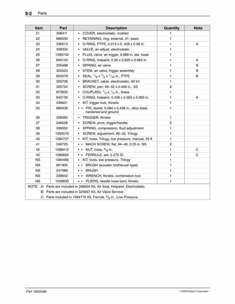
Parts8-2
Part 1093558A � 2009 Nordson Corporation
NoteQuantityDescriptionPartItem21 336411 � COVER, electrostatic, molded 1
22 986030 � RETAINING, ring, external, 31, basic 1
23 336512 � O-RING, PTFE, 0.313 x 0. 438 x 0.06 in. 1 A
24 336334 � VALVE, air adjust, electrostatic 1
25 1090742 � PLUG, valve, air trigger, 0.688 in. dia. head 1
26 940140 � O-RING, hotpaint, 0.50 x 0.625 x 0.063 in. 1 A
27 325499 � SPRING, air valve 1 B
28 325523 � STEM, air valve, trigger assembly 1 B
29 955076 � SEAL, 1/8 x 1/4 x 1/16 in., PTFE 1 B
30 325736 � BRACKET, cable, electrostatic, 60 kV 1
31 325754 � SCREW, pan, #8−32 x 0.406 in., SS 2
32 973505 � COUPLING, 1/4 x 1/4 in., brass 1
33 940130 � O-RING, hotpaint, 0.438 x 0.563 x 0.063 in. 1 A
34 336631 � KIT, trigger lock, Kinetix 1
35 985438 � � PIN, dowel, 0.094 x 0.438 in., alloy steel,hardened and ground
1
36 336365 � TRIGGER, Kinetix 1
37 246526 � SCREW, pivot, trigger/handle 2
38 336353 � SPRING, compression, fluid adjustment 1
39 1093570 � SCREW, adjustment, #6−32, Trilogy 1
40 1094727 � KIT, hose, Trilogy, low pressure, manual, 25 ft 1
41 346725 � � MACH SCREW, flat, #4−40, 0.25 in. SS 2
42 1089413 � � NUT, hose, 3/8-in. 1 C
43 1090625 � � FERRULE, set, 0.375 ID 1 CNS 1094480 � KIT, tools, low pressure, Trilogy 1
NS 901905 � � BRUSH (wooden toothbrush type) 1
NS 247066 � � BRUSH 1
NS 336642 � � WRENCH, Kinetix, combination tool 1
NS 1028630 � � PLIERS, needle nose bent, Kinetix 1
NOTE A: Parts are included in 336634 Kit, Air Seal, Hotpaint, Electrostatic.
B: Parts are included in 325657 Kit, Air Valve Service.
C: Parts included in 1094775 Kit, Ferrule, 3/8 in., Low Pressure.

Parts 8-3
Part 1093558A� 2009 Nordson Corporation
1
5
4
2
5A
6
7
3
8
910
1112
13
14
15
12
23
24
2526
27
2829
16
17
19
2021 31
30
34
35
36
37
38
39
43
42
41
40
12
2218
32
33
Figure 8-1 Spray Gun Parts
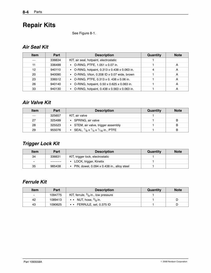
Parts8-4
Part 1093558A � 2009 Nordson Corporation
Repair KitsSee Figure 8-1.
Air Seal Kit
Item Part Description Quantity Note— 336634 KIT, air seal, hotpaint, electrostatic 1
11 336499 � O-RING, PTFE, 1.051 x 0.07 in. 1 A
12 940110 � O-RING, hotpaint, 0.313 x 0.438 x 0.063 in. 4 A
20 940090 � O-RING, Viton, 0.208 ID x 0.07 wide, brown 1 A
23 336512 � O-RING, PTFE, 0.313 x 0. 438 x 0.06 in. 1 A
26 940140 � O-RING, hotpaint, 0.50 x 0.625 x 0.063 in. 1 A
33 940130 � O-RING, hotpaint, 0.438 x 0.563 x 0.063 in. 1 A
Air Valve Kit
Item Part Description Quantity Note— 325657 KIT, air valve 1
27 325499 � SPRING, air valve 1 B
28 325523 � STEM, air valve, trigger assembly 1 B
29 955076 � SEAL, 1/8 x 1/4 x 1/16 in., PTFE 1 B
Trigger Lock Kit
Item Part Description Quantity Note34 336631 KIT, trigger lock, electrostatic 1
− −−−−−− � LOCK, trigger, Kinetix 1
35 985438 � PIN, dowel, 0.094 x 0.438 in., alloy steel 1
Ferrule Kit
Item Part Description Quantity Note− 1094775 KIT, ferrule, 3/8 in., low pressure 1
42 1089413 � � NUT, hose, 3/8 in. 1 D
43 1090625 � � FERRULE, set, 0.375 ID 1 D

Parts 8-5
Part 1093558A� 2009 Nordson Corporation
Recommended Spare PartsKeep the following parts in inventory to avoid unplanned downtime.Quantities listed support a single spray gun. Adjust order quantities basedon the number of spray guns in service.
Part Description Quantity Note336634 KIT, air seal, hotpaint, electrostatic 1
325657 KIT, air valve 1
1094777 KIT, cartridge, Trilogy 1
336631 KIT, trigger lock, electrostatic 1
336462 CABLE, 50 ft, Kinetix, manual, 5 conductor 11094727 KIT, hose, Trilogy, low pressure, manual, 25 ft 1
900349 LUBRICANT, O-ring, (MagnaLube) , 0.75-oz tube 1
247658 DIELECTRIC GREASE, applicator, 10 cc, 12 count 1
−−−−−− FLUID TIP 1 A
−−−−−− AIR CAP 1 A
1094025 POSTER, Parts, manual, solventborne, Trilogy 1
NOTE A: Refer to the Trilogy HVLP and Airspray Fluid Tip and Air Cap Selection Charts included with this manualfor available part numbers and descriptions.
Options
Air Caps and Fluid Tips Refer to the air cap and fluid tip guides included with this manual to selectand order air caps and fluid tips for your spray gun:
TC−09−01 Air Spray Fluid Tips and Air Caps
TC−09−02 HVLP Fluid Tips and Air Caps
Adhesives, Sealants, and LubricantsUse these adhesives, sealants, and lubricants when repairing your spraygun. Refer to the Repair or Installation sections for application instructions.
Part Description Quantity900464 ADHESIVE, threadlocking (Loctite Removable 242) 1
900349 LUBRICANT, PTFE grease, O-ring, (MagnaLube) , 0.75-oz tube 1
247658 DIELECTRIC GREASE, applicator, 10 cc, 12 count 1

Parts8-6
Part 1093558A � 2009 Nordson Corporation
Cable Extension
Part Description Quantity Note336531 CABLE, 50 ft, electrostatic, extension 1
Fluid and Air Hoses and Fittings
Part Description Quantity Note1074130 HOSE, air, w/1/4 in. NPSF fittings, 30 ft, packaged 1
1074131 HOSE, air, w/1/4 in. NPSF fittings, 50 ft, packaged 1
1074132 HOSE, air, w/1/4 in. NPSF fittings, 100 ft, packaged 1
336470 COUPLING, 3/8 in. NPMSM, brass 1
972637 COUPLING, 3/8 in. NPMSM, brass, nickel plate 1
336497 STEM, swivel, 3/8 in. NPS, Hosco 1
336495 CONNECTOR, quick disconnect, 3/8 in. NPS, Hosco 1
336496 CONNECTOR, circulation, 3/8 in. NPS, PLH−RY−6, stainless steel 1 A
NOTE A: Use to circulate fluid at the gun handle.
HVLP Compliance Kit
Item Part Description Quantity Note— −−−−−− COMPLIANCE KIT 1 A
1 325643 � GAUGE, air, 1.5-in. diameter, 0−30 psi 2
2 972937 � CONNECTOR, female, 1/8-in. tube x1/8-in. NPT
2
3 −−−−−− � TUBING, 1/8-in. diameter, gray (18 in.) 3
4 −−−−−− � CAP, compliance, HVLP 1 A
5 971620 � � CONNECTOR, barbed, #3-56 x 1/8 in., brass 2
NOTE A: Refer to the Trilogy HVLP Fluid Tip and Air Cap Selection Chart included with this manual for kit and aircap part numbers.
11 2
2
3
4
5
Figure 8-3 HVLP Compliance Kit Parts

Safety Note TRILOGY/ATEX Page 1
DOC13013-02
1. DESCRIPTION of EQUIPMENT TRILOGY Manual Low Pressure Air Spray / KVLP (WATERBORNE) are hand-held applicators for spraying of waterborne paint. They are supplied by HD ISO-FLO (voltage block system) and EPS6 manual controller (associated apparatus). The HD ISO-FLO system and EPS6 manual controller are installed in a safe area. The category 2 G of the TRILOGY manual applicator is strictly related to the use of waterborne paints only.
2. ELECTRICAL CHARACTERISTICS
KINETIX / TRILOGY manual waterborne applicator Maximum voltage: 60kV
Maximum current. 150µA Ambient temperature: 0°C to +40°C EPS6 Manual Controller Rated voltage: 120 – 240VAC Rated frequency: 50 / 60 Hz Rated current. 0.75 A Maximum voltage out: 60kV
Maximum current out: 150µA HD ISO-FLO Manual System Maximum voltage: 60kV
3. MARKING
1180 II 2 G 1180 n° of notified body (ATEX surveillance) II group II (surface) 2 category 2 apparatus G explosive atmospheres caused by gas, mists or vapours of
waterborne 94 mJ Maximum energy at the gun tip.
Hazardous area Categories according to 94/9/CE Directive Gas, mists or vapours Zone 0 1 G
Gas, mists or vapours Zone 1 2 G
Gas, mists or vapours Zone 2 3 G

Safety Note TRILOGY/ATEX Page. 2 DOC13013-02
4. SAFETY INSTRUCTIONS FOR THE INSTALLATION IN HAZARDOUS AREA
TRILOGY liquid applicator shall be installed & maintained according to the applicable standards regarding electrical installations in hazardous area. Before the installation READ CAREFULLY the INSTRUCTION MANUAL of the TRILOGY liquid applicator and the associated apparatus HD Manual ISO-FLO and EPS6. FOR USE WITH WATERBORNE PAINTS ONLY!
5. EXAMPLE OF APPLICATION This shows the applicators and how a typical system is configured.

Safety Note TRILOGY/ATEX Page. 3 DOC13013-02
6. DECLARATION OF CONFORMITY Nordson Corporation Headquarters in Westlake Ohio, USA declare under our sole responsibility that the products TRILOGY Liquid Applicators including Air Spray / KVLP Models used with HD Manual ISO-FLO
and EPS6. FOR USE WITH WATERBORNE PAINTS ONLY. to which this declaration relates complies with the following Directives: - Machinery Directive 2006/42/EC - EMC Directive 2004/108/EC - ATEX Directive 94/9/EC The conformity are under observance of the following standards or standards documents: EN12100 (2003) EN61000-6-2 (2007) FM7260 (1996) EN50059 (1990) EN61000-6-3 (2005) EN60204 (2006) EN55011 (2009) Type of protection: - II 2 G, max energy 94 mJ, Ambient temperature: 0°C to +40°C EC type-examination certificate no: - CESI 01 ATEX 030 - Milan Italy N° of notified body (ATEX surveillance) - 1180 (Baseefa) Buxton, Derbyshire, UK
Date: 31 May 2016 Marco Ciccone Engineering Manager Nordson Authorized Representative in the EU Contact: Operations Manager Industrial Coating Systems Nordson Deutschland GmbH Heinrich-Hertz-StraBe 42-44 D-40699 Erkrath