TRIDENT NETWORK ANALYSER USER’S GUIDE · Measure and assess the voltage quality according to the...
48
M A D E S.A. au capital de 270 130 € 167, Impasse de la garrigue F 83210 LA FARLEDE Tél:+ 33 (0) 494 083 198 – FAX : + 33 (0) 494 082 879 E-mail: [email protected] - Web : www.made-sa.com TRIDENT NETWORK ANALYSER USER’S GUIDE August 2009 MADE-V_1._20
Transcript of TRIDENT NETWORK ANALYSER USER’S GUIDE · Measure and assess the voltage quality according to the...

M A D ES.A. au capital de 270 130 €
167, Impasse de la garrigueF 83210 LA FARLEDE
Tél:+ 33 (0) 494 083 198 – FAX : + 33 (0) 494 082 879E-mail: [email protected] - Web : www.made-sa.com
TRIDENT
NETWORK ANALYSER
USER’S GUIDE
August 2009
MADE-V_1._20
GU_TRIDENT_V_1_20_EN 2/47
CONTENTS
CHAPTER 1 - TRIDENT OVERVIEW .......................................................................................................................................................... 4
1.1 USING TRIDENT ............................................................................................................................................................................ 4 1.2 GENERAL DESCRIPTION ............................................................................................................................................................. 5
1.2.1 Functions .............................................................................................................................................................................. 5 1.2.2 Recordings ............................................................................................................................................................................ 6
1.3 TRIDENT 3U3I ET 1U1I .................................................................................................................................................................. 7 1.4 MANUAL CONTENTS ................................................................................................................................................................... 7
CHAPTER 2 - REFERENCE DOCUMENTS ................................................................................................................................................ 8
CHAPTER 3 - TERMINOLOGY .................................................................................................................................................................... 9
3.1 ABREVIATIONS ............................................................................................................................................................................. 9 3.2 GLOSSARY ..................................................................................................................................................................................... 9
CHAPTER 4 - INSTALLATION & START-UP .......................................................................................................................................... 10
4.1 1ST START-UP ............................................................................................................................................................................... 10 4.1.1 Connection to the TRIDENT supply .................................................................................................................................. 10 4.1.2 Turn on ............................................................................................................................................................................... 10
4.2 GENERAL RULES FOR THE USE OF THE USER INTERFACE ................................................................................................ 10 4.3 COMMUNICATION WITH A PC .................................................................................................................................................... 11
4.3.1 Communication configuration ............................................................................................................................................ 11
CHAPTER 5 - DETAILS OF USE AND DESCRIPTION ........................................................................................................................... 13
5.1 ORGANISATION OF THE TRIDENT MENUS ............................................................................................................................... 13 5.2 CARRYING OUT A MEASUREMENT PROGRAM .................................................................................................................... 14
5.2.1 Typical measurement program ........................................................................................................................................... 14 5.2.2 Programming TRIDENT .................................................................................................................................................... 15 5.2.3 Installation on site ............................................................................................................................................................... 21 5.2.4 Turn-On and checking connections .................................................................................................................................... 23 5.2.5 Starting, Stopping and Ending a measurement program. .................................................................................................... 24 5.2.6 Results of a measurement program ..................................................................................................................................... 25
5.3 DIVERSE FUNCTIONS ................................................................................................................................................................. 29 5.3.1 Setting the Date & Time ..................................................................................................................................................... 29 5.3.2 Access Code ....................................................................................................................................................................... 29
5.4 MEASUREMENT PRINCIPLES OF TRIDENT ............................................................................................................................ 30 5.4.1 Sampling ............................................................................................................................................................................. 30 5.4.2 Calculation of the 20ms RMS values and fault detection ................................................................................................... 30 5.4.3 Calculation of slow variations ............................................................................................................................................ 31 5.4.4 Calculation of the frequency ............................................................................................................................................... 32 5.4.5 Management of the slow overvalues and of their recording. .............................................................................................. 32 5.4.6 Maxima of I and P (except 1U, 3U et 3U3V) ..................................................................................................................... 32 5.4.7 Management of overfrequencies ......................................................................................................................................... 32 5.4.8 Calculation of voltage imbalances (TRIDENT 3U3V) ....................................................................................................... 33
CHAPTER 6 - MAINTENANCE & TROUBLESHOOTING ..................................................................................................................... 34
CHAPTER 7 - DETAILLED TECHNICAL FEATURES ........................................................................................................................... 35
7.1 TEMPERATURES ......................................................................................................................................................................... 35 7.2 PHYSICAL FORM ......................................................................................................................................................................... 35 7.3 SUPPLIES ...................................................................................................................................................................................... 35 7.4 MEASUREMENT INPUTS & ACCURACIES .............................................................................................................................. 36 7.5 STANDARDS ................................................................................................................................................................................ 37
CHAPTER 8 - HARMONICS : SUPPLEMENT TO THE TRIDENT USER’S MANUEL ..................................................................... 38
8.1 OVERVIEW OF THE APPLICATION « HARMONICS » FOR TRIDENT .................................................................................. 38 8.2 DEFINITIONS ................................................................................................................................................................................ 38 8.3 DETAILLED DESCRIPTION ........................................................................................................................................................ 40 8.4 INSTALLATION AND START-UP SEE CHAPTER 4. ....................................................................................................................... 40 8.5 DETAILS OF USE AND DESCRIPTION ...................................................................................................................................... 40
8.5.1 TRIDENT menu organisation ............................................................................................................................................. 40 8.5.2 Carrying out a measurement program................................................................................................................................. 41
GU_TRIDENT_V_1_20_EN 3/47
8.5.3 Diverse functions ................................................................................................................................................................ 47 8.5.4 Measurement principles of TRIDENT H ........................................................................................................................... 47
8.6 MAINTENANCE AND TROUBLESHOOTING SEE THE TRIDENT 3U3I MANUAL..................................................................... 48 8.7 DETAILLED TECHNICAL FEATURES SEE TRIDENT 3U3I MANUAL. .................................................................................... 48
8.7.1 Measurement inputs and accuracies See TRIDENT 3U3I manual. .................................................................................... 48
GU_TRIDENT_V_1_20_EN 4/47
CHAPTER 1 - TRIDENT OVERVIEW
1.1 USING TRIDENT
The TRIDENT range includes the following products:
TRIDENT “Blind” including:
Trident 1U
Trident 1U1I
Trident 3U
Trident 3U3I
TRIDENT standard:
Trident 3U
Trident 3U3V
Trident 3U3I
With a harmonic option on the TRIDENT 3U3I.
Remark: This note describes the use of any product in the TRIDENT range. The display functions and use of the keyboard that are described here do not apply to a
“Blind” TRIDENT.
Similarly, descriptions of the measurement functions of triphase units are to be considered in
monophase for versions 1U and 1U1I.
TRIDENT is used to perform measurement programs on three phase & single-phase low voltage (400V) and
medium voltage (11 or 20kV.) electrical networks using measurement sensors.
The device has only low voltage inputs.
TRIDENT 3U3I /I is intended for use with current clamps having a current output of 1A or 5A.
TRIDENT 3U3I /V is intended for use with current clamps having a voltage output of 1V to 5V.
During a program, it records:
Voltage faults, including those on the Neutral/Earth,
A running record of the RMS values of the voltages and currents, as well as the total active power,
The durations of frequency out-of-limits (measured on the phase 1 voltage input),
The durations of out-of-limits of the mean values of the voltages,
Five date stamped maxima of current in 1 sec. values and P in mean values (for the product of U & I).
TRIDENT has a local user interface, consisting of an LCD display of 4 lines of 20 characters each and 4
buttons (except, of course, for the « Blind » versions).
Communication with a PC is made via a series connection RS232 (RS485 is optional). The WINTRID PC
software is a necessary complement for TRIDENT which enables the study and analysis of the measurements
made by the equipment.

GU_TRIDENT_V_1_20_EN 5/47
1.2 GENERAL DESCRIPTION
1.2.1 Functions
TRIDENT is a portable recorder, light and field-tested, which records & analyses the voltage,
current and power on single and three phase electrical networks.
TRIDENT can:
Measure and assess the voltage quality according to the EN 50160 Standard: "Voltage
characteristics of the electricity supplied by public distribution networks ", notably:
Slow voltage variations,
Brief overvoltages,
Brief dips,
Brief & long interruptions,
Frequency variations,
Overvoltages between neutral & earth (except monophase products).
Record the evolution of the continuous measurements of the 3 currents and the 3 voltages taken
simultaneously at the same measurement point,
Carry out an analysis of the active power consumption at this point of the network.
TRIDENT is supplied with the WINTRID display and configuration software, which runs on the
WINDOWS 3.11, 95, 98, NT and XP versions.
WINTRID enables :
The configuration of the computer,
The configuration of TRIDENT,
The consultation of the instantaneous measurements,
The sampling and graphical representation of the slow variations in voltage, current and power
superposed on the voltage events,
The preparation of a list of all events and their characteristics,
A statistical analysis of the events,
Rapid and simple printing of reports in colour,
The transfer of data to other applications (spread-sheets, word processing...).

GU_TRIDENT_V_1_20_EN 6/47
1.2.2 Recordings
The quality of the 3 voltages, either simple (i.e. Phase to Neutral in a star network) or line (i.e.
between phases in a delta network), is continuously monitored by TRIDENT.
Slow Variations of Amplitude:
The number of times the mean voltage passes the high & low thresholds is totalled.
Rapid Variations of Amplitude:
TRIDENT can sense and record any voltage variation with a time resolution of 2ms.
TRIDENT records 3 types of faults according to the threshold passed by the voltage:
overvoltages,
voltage dips,
Long interruptions,
Brief interruptions.
A minimum duration threshold, programmed by the user, is used to avoid recording very brief
events.
A voltage fault is recorded with:
start time & date,
duration,
type,
phase,
the mean voltage during the fault,
a 10ms peak voltage during the fault,
the 1 second values of the 3 U (or V) and 3 I before the fault,
the 1 second values of the 3 U (or V) and 3 I after the fault,
Overvoltage between Earth & Neutral :
The voltage between neutral & earth is measured continuously over 20ms rolling each 2ms.
Crossing a threshold starts the recording of an Earth/Neutral overvoltage, having the same
characteristics as for a voltage fault.
Frequency monitoring :
The frequency is continuously measured in the form of a 10 second mean on the phase 1 voltage.
Crossings of a high or low threshold are totalled.
Power and Current Maxima:
The 5 highest values of the currents (1 second mean, all phases together) are recorded & dated.
The 5 highest values of the active total power are recorded & dated.
GU_TRIDENT_V_1_20_EN 7/47
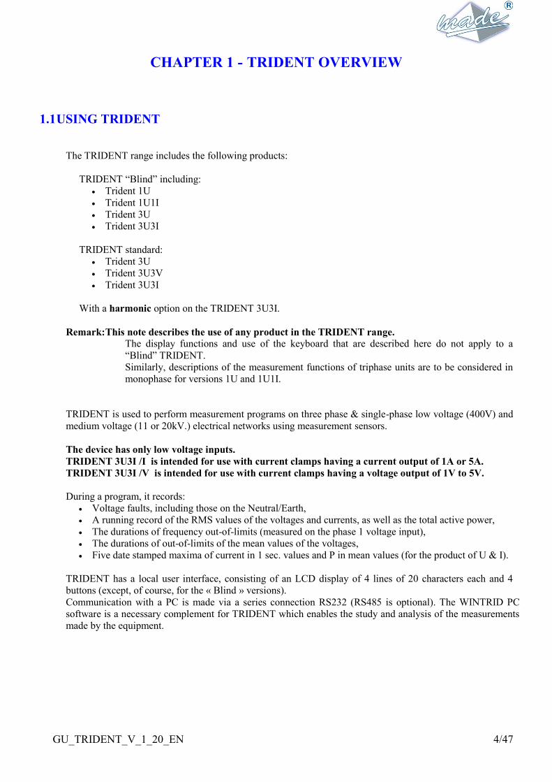
1.3 TRIDENT 3U3I ET 1U1I
TRIDENT 3U3I TRIDENT 1U1I « BLIND »
1.4 MANUAL CONTENTS
The reference documents listed in CHAPTER 2 and CHAPTER 3 contain the glossary of specific terms.
CHAPTER 4 gives the procedure to follow for the first Start-Up of TRIDENT 3U3I. CHAPTER 5 describes
in detail the use of TRIDENT on site and gives the list of the different data available.
GU_TRIDENT_V_1_20_EN 8/47
CHAPTER 2 - REFERENCE DOCUMENTS
WINTRID software manual: LOG PC 0006
Voltage Quality:
EN 50160 : Caractéristiques de la voltage fournie par les réseaux publics de distribution.
Security Regulations :
EN 61010-1, édition 1993, plus amendement A2 : Règles de sécurité pour appareils électriques de
mesurage, de régulation et de laboratoire.
Electromagnetic compatibility:
NF EN 50 081-2, décembre1993 : norme générique émission. Partie 2 : environnement industriel.
EN 55 011 : limites et méthodes de mesure des caractéristiques de perturbations électriques des
appareils industriels, scientifiques et médicaux (ISM) to fréquence radioélectrique.
Susceptibility to perturbations :
NF EN 50 082-2, juin 1995 : norme générique immunité. Partie 2 : environnement industriel.

GU_TRIDENT_V_1_20_EN 9/47
CHAPTER 3 - TERMINOLOGY
3.1 ABREVIATIONS
HTA: high voltage used for electrical supply, with anominal RMS ranging from 1kV to 50Kv
HTB: high voltage used for electrical supply, with a nominal RMS superior to 50kV
LV : Low Voltage electrical supply, with a nominal RMS value ofless than 1kV.
TRIDENT only directly measures LV with a the nominal RMS value of less than 400V.
VT : Voltage transformer, placed between the high voltage to be measured and the TRIDENT inputs.
CT : Current transformer. In this document clamps with current outputs (for TRIDENT 3U3I /I) and
clamps with voltage outputs (for TRIDENT 3U3I /U) have the same abbreviation.
3.2 GLOSSARY
Voltage dips: rapid and temporary voltage drop measured below the programmed threshold,
followed by a re-establishment of the voltage, or an interruption.
Overvoltage: temporary voltage increase, slow or rapid, measured above the programmed threshold.
Brief interruption : disappearance or large voltage drop measured during a brief instant. According to the
EN50160 standard, a brief interruption is less than 3mn.
Long interruption : disappearance or large drop of voltage. According to the EN50160 standard, a long
interruption is over 3mn.
Rapid Variation, voltage fault : abrupt variation of the voltage RMS value measured over at least
one cycle (rise, dip or break) followed by a re-establishment of the
voltage or a change to another type of rapid variation. A rapid
variation over the detection thresholds of TRIDENT is considered as
a voltage fault.
Slow Variations: variations of the mean RMS values of the physical parameter measured (voltage,
current or power).

GU_TRIDENT_V_1_20_EN 10/47
CHAPTER 4 - INSTALLATION & START-UP
4.1 1st START-UP
4.1.1 Connection to the TRIDENT supply
On reception, TRIDENT should be connected close to the PC which will serve as the workstation
for the recordings, in order to open communication with the WINTRID software.
For the 1st start-up, it is sufficient to insert the plug of the power cable supplied with the equipment
in the auxiliary power socket and the other end in the mains 50Hz, 230V A.C.
The supply mode selected must be Auxiliaire 230V,10VA max.
On site, it uses the voltage measurement inputs as a source of supply. This supply option is
explained in paragraph 5.2.3 Installation on site and in this case the switch should be in the position
Entrées mesures N-V1 230V,10VA max.
4.1.2 Turn on
The device is turned on by switching the marche/arrêt switch to position I. Turn the device
offsimply by inversing the switch or in the absence of an alternative supply when the internal
battery is discharged.
Upon start-up, the red light is lit and the screen shows :
T R I D E N T 3 U 3 I / I V 1 . 7
N O T R E C O R D I N G
3 0 / 1 0 / 1 9 9 8 1 1 : 1 0 : 2 4
M A D E S A
It shows the type of TRIDENT, 3U3I, as well as the software version.
This screen also indicates the internal date and time of TRIDENT. This time can be slightly
different from the correct time because of possible drift during storage.
Pressing the button VAL brings up the main menu.
4.2 GENERAL RULES FOR THE USE OF THE USER INTERFACE
On the front face of TRIDENT is a 4 line, 20 character display, as well as a 4 key keyboard:
+ (plus),
- (minus),
(left arrow),
(right arrow, VAL)
This group is enough to configure or operate TRIDENT.
All the keys autorepeat if held down.
Generally :
The keys +/- are used to move an arrow on the screen, or to modify the value of a figure being entered
(underlined by the cursor).
The key can, depending on the position of the cursor, move to the digit or field following, or
validate a page and move to the following page.
The key can, depending on the position of the cursor, move to the preceding digit or field, or return
GU_TRIDENT_V_1_20_EN 11/47
to the preceding page.
To enter a value :
Numerical entries are made by moving the cursor (underlining the relevant) using the 2 arrows.
If a figure is underlined by the cursor, the keys + & - are used to increment or decrement this figure.
Sometimes the possible values are pre-defined (communication speeds for example), in which case the
keys + or – move in the list of values.
Incorrect entry :
If a value is entered incorrectly (outside the permitted limits for example), when the number is validated,
TRIDENT returns the cursor to the beginning of the field.
4.3 COMMUNICATION with a PC
4.3.1 Communication configuration
As delivered, TRIDENT is configured with the following communication parameters, identical to
those of WINTRID when it is installed :
Communication speed : 9600 bauds,
Adress N°: 001,
Communication protocol: RS232.
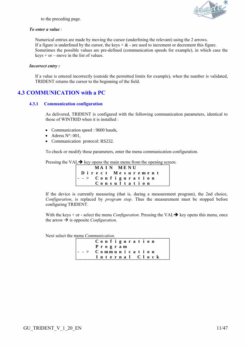
To check or modify these parameters, enter the menu communication configuration.
Pressing the VAL key opens the main menu from the opening screen.
M A I N M E N U
D i r e c t M e s u r e m e n t
- - > C o n f i g u r a t i o n
C o n s u l t a t i o n
If the device is currently measuring (that is, during a measurement program), the 2nd choice,
Configuration, is replaced by program stop. Thus the measurement must be stopped before
configuring TRIDENT.
With the keys + or - select the menu Configuration. Pressing the VAL key opens this menu, once
the arrow is opposite Configuration.
Next select the menu Communication.
C o n f i g u r a t i o n
P r o g r a m
- - > C o m m u n i c a t i o n
I n t e r n a l C l o c k
GU_TRIDENT_V_1_20_EN 12/47
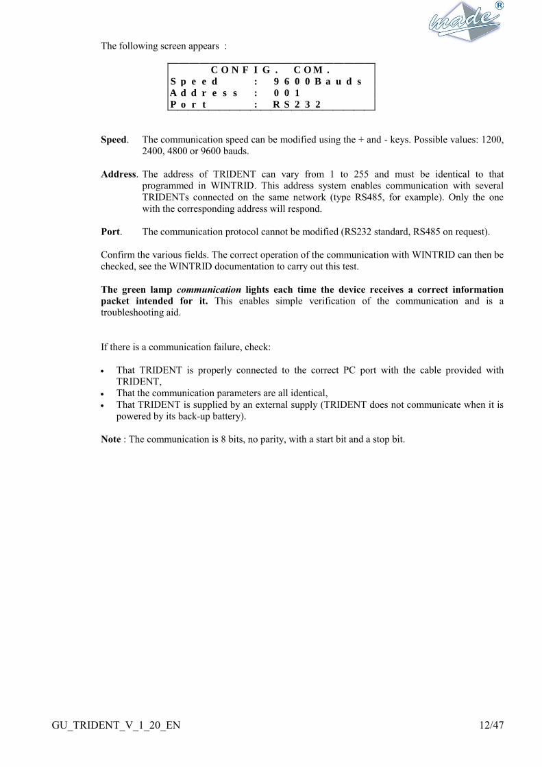
The following screen appears :
C O N F I G . C O M .
S p e e d : 9 6 0 0 B a u d s
A d d r e s s : 0 0 1
P o r t : R S 2 3 2
Speed. The communication speed can be modified using the + and - keys. Possible values: 1200,
2400, 4800 or 9600 bauds.
Address. The address of TRIDENT can vary from 1 to 255 and must be identical to that
programmed in WINTRID. This address system enables communication with several
TRIDENTs connected on the same network (type RS485, for example). Only the one
with the corresponding address will respond.
Port. The communication protocol cannot be modified (RS232 standard, RS485 on request).
Confirm the various fields. The correct operation of the communication with WINTRID can then be
checked, see the WINTRID documentation to carry out this test.
The green lamp communication lights each time the device receives a correct information
packet intended for it. This enables simple verification of the communication and is a
troubleshooting aid.
If there is a communication failure, check:
That TRIDENT is properly connected to the correct PC port with the cable provided with
TRIDENT,
That the communication parameters are all identical,
That TRIDENT is supplied by an external supply (TRIDENT does not communicate when it is
powered by its back-up battery).
Note : The communication is 8 bits, no parity, with a start bit and a stop bit.

GU_TRIDENT_V_1_20_EN 13/47
CHAPTER 5 - DETAILS OF USE AND DESCRIPTION
5.1 ORGANISATION of the TRIDENT MENUS
The TRIDENT menus follow the arborescence below when the device is not measuring :
Welcome Not Recording
Direct Measurements
Consultation of the instantaneous values (2 pages)
Configuration
Configuration of the next program
Confirmation
Program parameters (7 pages)
Time & Date of start & finish
Parameters of communication
Setting the internal clock
Consultation of the results of the last program
Consultation of the faults
Total number n of faults
Detail of each fault (n pages)
Consultation of the slow variations
Overvoltages V1, V2 and V3 (3 pages)
Maxima of I
Maxima of P
Frequency out-of-limits
Consultation of the program parameters (6 pages)
When a program is started the configuration menu is no longer accessible. It is replaced by the option of
stopping the running program :
Welcome Program (program running)
Direct Measurements
Program Stop
Consultation of the results of the running program

GU_TRIDENT_V_1_20_EN 14/47
5.2 CARRYING OUT A MEASUREMENT PROGRAM
5.2.1 Typical measurement program
Before beginning a measurement program, the device must be programmed with the correct
measurement parameters.
Parameters can be set in several ways:
The device can be programmed with the help of the WINTRID software that offers a user-friendly
interface. As all measurement operations can be programmed in advance, the device can be
programed at the measurement site or elsewhere, for example close to the office PC.
In the case of a deferred start to the program, TRIDENT must be installed with all its connections
before the programmed start time in order avoid recording false events (notably interruptions).
TRIDENT can also be programed once installed, either with WINTRID, or with the use of its local
interface.
To help with the local interface, TRIDENT has in memory two Standard measurement programs
one of which can be installed at the start of a program. This avoids the need for full programming in
detail. These standard programs can be modified to suit the requirement with the help of the
WINTRID software.
Before starting the program, TRIDENT will ask for confirmation of the clamp outputs (voltage &
current) and dates of the start and end of the program.
A program can have a predefined end time or can be of indeterminate length.
Once the connections are in place, the instantaneous measurements can be verified to confirm the
correct connection of the device.
The measurement program starts as the internal clock reaches the programmed time, or if that time
is passed when the device is turned on.
The program continues :
either until the user sends a stop command by WINTRID, or by the local user-interface,
or until the chosen end of the program, if there is one.
In case of an interruption of the program (battery exhausted, M/A switch,...), the program restarts at
the re-supply.
The results summary of the measurement program can be obtained during the progress of the
program if TRIDENT is still connected to the PC. Otherwise at the end of the measurement
program TRIDENT is connected to the PC. The transfer begins automatically and the analysis is
then performed by WINTRID.
The main results of the program in progress can also be seen using the local interface.

GU_TRIDENT_V_1_20_EN 15/47
5.2.2 Programming TRIDENT
TRIDENT can be completely configured using its local interface, in the same way as using
WINTRID.
For this, in the menu configuration, choose Program and enter:
C O N F I G U R A T I O N M E N U
- - > P r o g r a m
C O m m u n i c a t i o n
I n t e r n a l C l o c k
TRIDENT warns you that the last program will be erased permanently from the memory. Check
carefully that this program has been transferred to WINTRID.
A T T E N T I O N ! ! !
T h e m e m o r y w i l l b e
e r a s e d . C o n t i n u e ?
N O V a l i d a t i o n - >
The +/- keys move between NO & YES, and the VAL key confirms the choice.
Confirm with YES to enter into the configuration menu.
There are 7 successive pages of configuration. They are all numbered and you can return at all times
to the entries on the previous page with the key.
Choice of a standard or manual configuration:
C O N F I G . P R O G R A M 1 / 7
S t 1 : L I b e l l e 0 1
- - > S t 2 : L I b e l l e 0 2
C o n f i g . m a n u a l
The user must choose between one of the 2 Standards (of which the name and parameters have been
initialised by the WINTRID software), or the local configuration of all parameters.
The standards contain all parameters that will be required subsequently in the manual configuration.
Their names are those chosen at the time of their modification in WINTRID.
If one of the 2 Standards is chosen, it is only necessary to enter or validate the types of TC and TP
and the times and dates of the start and end of the program.
GU_TRIDENT_V_1_20_EN 16/47
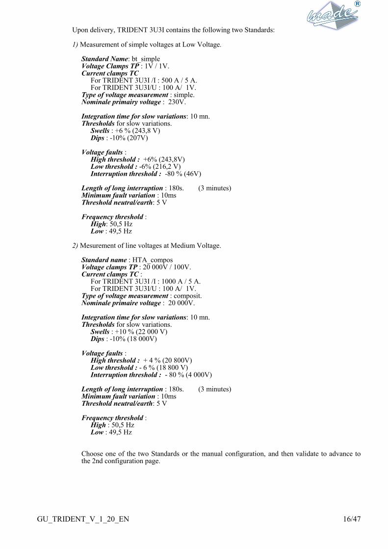
Upon delivery, TRIDENT 3U3I contains the following two Standards: 1) Measurement of simple voltages at Low Voltage.
Standard Name: bt_simple Voltage Clamps TP : 1V / 1V. Current clamps TC
For TRIDENT 3U3I /I : 500 A / 5 A. For TRIDENT 3U3I/U : 100 A/ 1V.
Type of voltage measurement : simple. Nominale primairy voltage : 230V. Integration time for slow variations: 10 mn. Thresholds for slow variations.
Swells : +6 % (243,8 V) Dips : -10% (207V)
Voltage faults :
High threshold : +6% (243,8V) Low threshold : -6% (216,2 V) Interruption threshold : -80 % (46V)
Length of long interruption : 180s. (3 minutes) Minimum fault variation : 10ms Threshold neutral/earth: 5 V Frequency threshold :
High: 50,5 Hz Low : 49,5 Hz
2) Mesurement of line voltages at Medium Voltage.
Standard name : HTA_compos Voltage clamps TP : 20 000V / 100V. Current clamps TC :
For TRIDENT 3U3I /I : 1000 A / 5 A. For TRIDENT 3U3I/U : 100 A/ 1V.
Type of voltage measurement : composit. Nominale primaire voltage : 20 000V. Integration time for slow variations: 10 mn. Thresholds for slow variations.
Swells : +10 % (22 000 V) Dips : -10% (18 000V)
Voltage faults :
High threshold : + 4 % (20 800V) Low threshold : - 6 % (18 800 V) Interruption threshold : - 80 % (4 000V)
Length of long interruption : 180s. (3 minutes) Minimum fault variation : 10ms Threshold neutral/earth: 5 V Frequency threshold :
High : 50,5 Hz Low : 49,5 Hz
Choose one of the two Standards or the manual configuration, and then validate to advance to the 2nd configuration page.

GU_TRIDENT_V_1_20_EN 17/47
Characteristics of the network to be measured :
C O N F I G . P R O G R A M 2 / 7
T V : 2 0 0 0 0 / 1 0 0 . 0 V
C T : 1 0 0 0 A 1 . 0 V
S i m p l e V n = 1 5 0 0 0 . 0 V
TRIDENT 3U3I makes the measurements directly on the network or via voltage transformers (TP) and current transformers (TC) Voltages :
TRIDENT can measure up to 440 V between phases and between phase and neutral. To configure the voltage clamps it is necessary to enter or validate the values of the primary and secondary. The primary can be between 1 and 99999V (without decimal). The secondary can be between 1 and 999,9V.
NOTE : the transformation ratio does not apply to the earth/neutral voltage. Currents :
TRIDENT 3U3I /I accepts only current clamps with current output. It can measure directly up to 6A per phase. To configure the CTs it is necessary to enter or validate values for the primary and the secondary. The primary of the CTs can be between 1 and 9999A. The secondary is 1 or 5A. TRIDENT 3U3I /I is calibrated to measure 5A inputs. If you choose 1A, the measurement precision will be slightly degraded. The neutral current is calculated and not measured. TRIDENT 3U3I /U accepts only clamps with current output. It can measure directly up to 5V per phase. To configure the CTs it is necessary to enter or validate values of the primary and the secondary. The primary of the CTs can be between 1 and 9999A. TRIDENT 3U3I /U is calibrated to measure from 5V inputs. If you choose a lower value, the measurement precision will be slightly degraded. TRIDENT carries out different measurements according to the network selected : simple voltages : TRIDENT gives values of the voltages between phase and neutral and
makes all events calculations according to these values. In the absence of a neutral, an internal neutral is recreated by a high impedance resistive bridge.
line voltages : TRIDENT gives real voltage values between phases U12, U23, U31 and does all events calculations according to these values.
monophase (simple V1 voltage only) : TRIDENT makes measurements between V1 and neutral and of the current I1 and ignores other channels.
Nominal voltage :
The nominal voltage of the primary. Its value can be between 50V and 99999,9V and must be expressed as the voltage between phase and neutral Vn if simple or monophase has been selected, otherwise as line voltage Un. This value is important because all thresholds are referenced to it. Recommendation: if the real value is different from the theoretical nominal voltage, it is worthwhile to enter the real value after having consulted the measurements taken by TRIDENT after its installation. After having checked the modifications, validate them. If one of the two standards has been chosen, validate all the values to move directly to the last page of program configuration (start date). Otherwise advance to the 3rd configuration page.

GU_TRIDENT_V_1_20_EN 18/47
Measuring slow variations:
C O N F I G . P R O G R A M 3 / 7
I n t E g S l o w V a r s 0 1 m n
T h r e s R : + 0 3 % ( 2 3 6 . 9 V )
T h r e s D r : - 0 3 % ( 2 2 3 . 1 V )
Select here the integration period of the slow voltage, current & power variations, and also the
thresholds of swells and sags. High thresholds determine limits over which the slow variations must
not pass, in accordance with the EN50160 standard.
Integration time for means :
This value can be between 1 and 60mn.
TRIDENT can record continuously 28 days of measurements with a 10 mn integration period. If
a longer period is chosen, the autonomy of TRIDENT changes.
Examples :
Period 3mn, TRIDENT records a little over 8 days.
Period 30 mns, TRIDENT records for nearly 3 months.
The TRIDENT memory is “circular”, that is to say that when it is full, the measurement program
continues, but the oldest recordings are replaced by the most recent.
Swells threshold : ThresholdH
This is entered as a percentage of the nominal voltage. This threshold can be between 3 and 30%
of the nominal voltage.
Sags threshold: ThresholdCr
This can be between -3 and -80% of the nominal voltage.
When one of the 2 thresholds is modified, the corresponding voltage (simple or line according to
the type of network selected) is displayed for information. If the nominal voltage is superior to
760V , TRIDENT displays voltages in kV.
After having checked the modifications, validate each one and advance to the 4th config. page.
Measurement of voltage faults:
C O N F I G . P R O G R A M 4 / 7
R i s e : + 0 9 % ( 2 5 0 . 7 V )
F a l l : - 0 5 % ( 2 1 8 . 5 V )
I n t e r . : - 8 7 % ( 0 2 9 . 9 V )
Here the quick variation parameters, thresholds of rises, dips and interruptions are configured.
Overvoltage thresholds determine limits over which the rapid variations (instantaneous) should not
pass, in accordance with the norm EN50160.
TRIDENT records up to 1000 faults within the limit of the circular memory: when it is full, the
measurement program continues, but the oldest records are replaced by the most recent.
Otherwise TRIDENT has a fault counter that memorizes the total number of faults detected
independently of the available memory, which enables better appreciation of the state of the
network during the program.
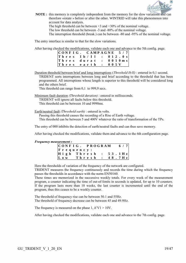
GU_TRIDENT_V_1_20_EN 19/47
NOTE : this memory is completely independent from the memory for the slow variations and can
therefore «rotate » before or after the other. WINTRID will take this phenomenon into
account for data analysis.
The high threshold can be between +3 and +30% of the nominal voltage.
The low threshold can be between -3 and -80% of the nominal voltage.
The interruption threshold (break.) can be between -80 and -95% of the nominal voltage.
The entry interface is similar to that for the slow variations.
After having checked the modifications, validate each one and advance to the 5th config. page.
C O N F I G . C A M P A G N E 5 / 7
T h r e s I b / I l : 0 1 2 . 0 s
T h r e s d u r a t : 0 0 1 0 m s
T h r e s e a r t h : 0 0 5 V
Duration threshold between brief and long interruptions (Threshold Ib/Il) : entered in 0,1 second.
TRIDENT sorts interruptions between long and brief according to the threshold that has been
programmed. All interruptions whose length is superior to this threshold will be considered long
and the others brief.
This threshold can range from 0,1 to 999,9 secs.
Minimum fault duration (Threshold duration) : entered in milliseconds.
TRIDENT will ignore all faults below this threshold.
This threshold can be between 10 and 9990ms.
Earth/neutral fault (Threshold earth) : entered in volts.
Passing this threshold causes the recording of a Rise of Earth voltage.
This threshold can be between 5 and 400V whatever the ratio of transformation of the TPs.
The entry of 000 inhibits the detection of earth/neutral faults and can thus save memory.
After having checked the modifications, validate them and advance to the 6th configuration page.
Frequency measurement :
C O N F I G . P R O G R A M 6 / 7
F r e q u e n c y :
H i g h T h r e s h : 5 3 . 1 H z
L o w T h r e s h : 4 8 . 7 H z
Here the thresholds of variation of the frequency of the network are configured.
TRIDENT measures the frequency continuously and records the time during which the frequency
passes the thresholds in accordance with the norm EN50160.
These times are memorized in the successive weekly totals. For every week of the measurement
program, a counter indicating the time of out-of-limits in seconds is updated, for up to 10 counters.
If the program lasts more than 10 weeks, the last counter is incremented until the end of the
program, thus this ceases to be a weekly counter.
The threshold of frequency rise can be between 50.1 and 55Hz.
The threshold of frequency decrease can be between 45 and 49.9Hz.
The frequency is measured on the phase 1, if V1 > 10V.
After having checked the modifications, validate each one and advance to the 7th config. page.

GU_TRIDENT_V_1_20_EN 20/47
Date & time of start & finish of the measurement program :
C O N F I G . P R O G R A M 7 / 7
S 0 1 / 0 1 / 2 0 0 0 0 0 : 0 0 : 0 0
E 0 1 / 0 1 / 2 0 0 0 0 0 : 0 0 : 0 0
The hour and the date of the start (S) and end (E) of the program must be entered. By default these
are the current time.
If they are not modified, the program will start immediately after the last field on this page has been
validated.
If the end date & time is identical or previous to that of the beginning, the program is of unlimited
length and will end only when terminated by the operator.
If the start date is before the present date, the program will start immediately after the last field has
been validated.
If the start date is later than the current date, TRIDENT will wait until this date to start the program.
The device can be turned off and moved, this parameter remains in the memory.
GU_TRIDENT_V_1_20_EN 21/47
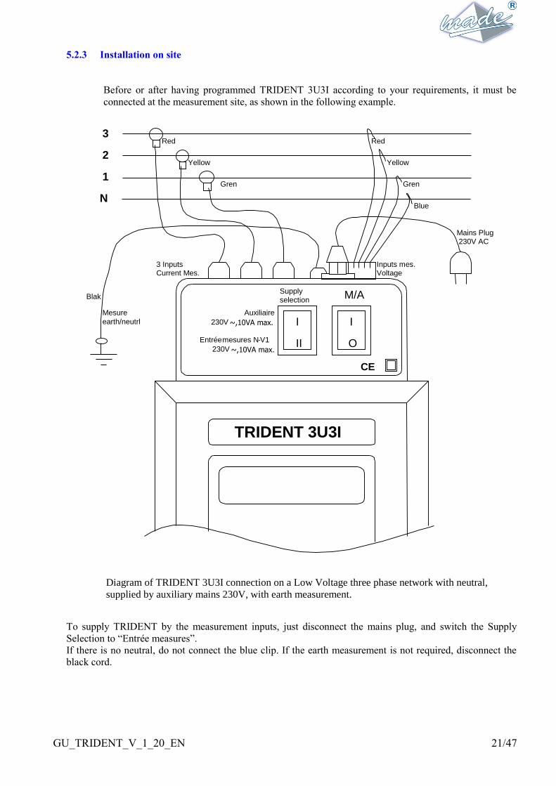
5.2.3 Installation on site
Before or after having programmed TRIDENT 3U3I according to your requirements, it must be
connected at the measurement site, as shown in the following example.
Diagram of TRIDENT 3U3I connection on a Low Voltage three phase network with neutral,
supplied by auxiliary mains 230V, with earth measurement.
To supply TRIDENT by the measurement inputs, just disconnect the mains plug, and switch the Supply
Selection to “Entrée measures”.
If there is no neutral, do not connect the blue clip. If the earth measurement is not required, disconnect the
black cord.
CE
M/A
Supply selection
Auxiliaire 230V ~,10VA max. I
II
I
O
TRIDENT 3U3I
Entrée mesures N - V1 230V ~,10VA max.
Inputs mes. Voltage
Red
Yellowaune
Gren
Blue
Mains Plug 230V AC
3 Inputs Current Mes.
3
2
1
N
Blak
Mesure earth/neutrl
Red
Yellow
Gren
GU_TRIDENT_V_1_20_EN 22/47
A) Supply characteristics and measurement inputs
Supply
2 supplies methods can be selected with the switch:
• Auxiliary supply :
- 230V A.C +/-20% 50/60Hz 10VAmax
• Supply by the measurement inputs between phase 1 and neutral :
- 230V A.C +/-20% 50/60Hz 10VAmax
Voltage measurement inputs
• measurement of simple or line voltage
• - 480V A.C max 50/60Hz 0,5VA max per channel
• this device is not intended for dc voltages measurements.
Current measurement inputs
TRIDENT 3U3I /I :
• Current measurement 1A or 5A via current output current clamps
• - 6Amax 0,5VA maximum per channel,
• this device is not intended for continuous currents measurements.
TRIDENT 3U3I /U ; 1U1I :
• voltage measurement from 0V to 5V via voltage output voltage clamps
• - 6Vmax 0,5VA maximum per channel,
• this device is not intended for dc voltages measurements.
B) Recommendations for connection
Wearing insulating gloves is recommended while making the connections.
Remark: The protective isolation given by the clamps is given in the measurement
framework for an insulated conductor.
Only the cables and the necessary connection accessories for the supply and measurement
inputs must be installed.
If TRIDENT is supplied using the measured voltage, the mains lead must not be connected.
Only cables for the voltage measurement inputs required must be equipped with their crocodile
clips. The other extremities of the voltage measurement cables must not have clips.
Only the necessary current measurement cables should be connected to the TRIDENT current
inputs.
The supply selection must be made with the switch before connecting the device to the power.
The conformity of the device can be compromised if it is not used as specified.
GU_TRIDENT_V_1_20_EN 23/47
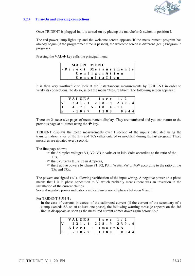
5.2.4 Turn-On and checking connections
Once TRIDENT is plugged in, it is turned-on by placing the marche/arrêt switch in position I.
The red power lamp lights up and the welcome screen appears. If the measurement program has
already begun (if the programmed time is passed), the welcome screen is different (see § Program in
progress).
Pressing the VAL key calls the principal menu.
M A I N M E N U
- D i r e c t M e a s u r e m e n t s
C o n f i g u r A t i o n
C o n s u l t a T i o n
It is then very worthwhile to look at the instantaneous measurements by TRIDENT in order to
verify its connections. To do so, select the menu “Mesure libre”. The following screen appears :
V A L U E S 1 s e c 1 / 2
V 2 3 1 . 1 2 2 8 . 9 2 3 0 . 4
I 4 . 7 0 5 . 1 8 4 . 1 1
P - 1 0 7 7 1 1 8 0 0 9 4 4
There are 2 successive pages of measurement display. They are numbered and you can return to the
previous page at all times using the key.
TRIDENT displays the mean measurements over 1 second of the inputs calculated using the
transformation ratios of the TPs and TCs either entered or modified during the last program. These
measures are updated every second.
The first page shows:
the 3 simples voltages V1, V2, V3 in volts or in kilo Volts according to the ratio of the
TPs,
the 3 currents I1, I2, I3 in Amperes,
the 3 active powers by phase P1, P2, P3 in Watts, kW or MW according to the ratio of the
TPs and TCs.
The powers are signed (+/-), allowing verification of the input wiring. A negative power on a phase
means that I is in phase opposition to V, which probably means there was an inversion in the
installation of the current clamps.
Several negative power indications indicate inversion of phases between V and I.
For TRIDENT 3U3I /I :
In the case of currents in excess of the calibrated current (if the current of the secondary of a
clamp exceeds 6A on an at least one phase), the following warning message appears on the 3rd
line. It disappears as soon as the measured current comes down again below 6A :
V A L U E S 1 s e c 1 / 2
V 2 3 1 . 1 2 2 8 . 9 2 3 0 . 4
A l e r t : I m a x = 6 A
P - 1 0 7 7 1 1 8 0 0 9 4 4
GU_TRIDENT_V_1_20_EN 24/47
For TRIDENT 3U3I /U :
In the case of voltages in excess of the calibrated voltage (if the voltage of the secondary of a
clamp exceeds 6V on at least one phase), the following warning message appears on the 3rd line.
It disappears as soon as the measured voltage comes down again below 6V.
V A L U E S 1 s e c 1 / 2
V 2 3 1 . 1 2 2 8 . 9 2 3 0 . 4
A l e r t : V m a x = 6 V
P - 1 0 7 7 1 1 8 0 0 9 4 4
The VAL key moves to the 2nd page :
V A L U E S 1 s e c 2 / 2
U 3 9 7 . 1 3 9 3 . 4 3 9 6 . 7
V e a 0 0 0 . 0 I N e 0 . 0 0
P t o t 1 0 4 5 F 5 0 . 0
The second page shows:
the 3 line voltages U12, U23, U31 in volts,
the voltage between earth and neutral in volts,
the neutral current in Amperes,
the total active power in Watts,
the frequency on the phase V1 in Hertz (averages over 10 seconds).
The VAL key sends back to the welcome screen.
5.2.5 Starting, Stopping and Ending a measurement program.
When the current time reaches or passes the program start time, TRIDENT begins the program.
The red lamp blinks throughout the entire program. The welcome screen appears as follow:
T R I D E N T 3 U 3 I / I V 1 . 7
P R O G R A M R U N N I N G
M A D E S A
If the “marche/arrêt” switch is changed, TRIDENT re-starts the program when power is restored.
In the same way, should the program be interrupted (battery exhausted, M/A switch,...), it will
restart at the re-supply.
To stop the program voluntarily, enter the main menu by pressing the VAL key.
M A I N M E N U
D i r e c t M e a s u r e m e n t s
- - > P r o g r a m S t o p
C o n s u l t a t i o n

GU_TRIDENT_V_1_20_EN 25/47
Select and validate Stop program. TRIDENT will ask for confirmation :
A T T E N T I O N ! ! !
T h e p r o g r a m r u n n i n g
w i l l b e s t o p p e d . . .
N O V a l i d a t i o n - >
The +/- keys switch between NO and YES and the VAL key validates the selection.
If YES is validated, the program is stopped.
TRIDENT returns to the welcome screen.
The program can be stopped by WINTRID, via the communication link.
Evidently, if the program is of fixed duration, it will stop automatically at the programmed time.
5.2.6 Results of a measurement program
In order to analyse the results, it is necessary to transfer the measurements to the P.C. via the series
link using WINTRID.
WINTRID enables the complete transfer of a measure program, whether finished or in progress. In
the second case, WINTRID indicates that the program is not finished until the transfer. However,
the program continues to its programmed termination without change. If there is a voltage fault at
the time of transfer, it will not be recorded.
While waiting for the transfer to begin, it can be useful to look at the measurements to make an
initial diagnosis.
M A I N M E N U
D i r e c t M e a s u r e m e n t s
C o n f i g u r a t i o n
- - > C o n s u l t a t i o n
For this, in the main menu, select and validate Consultation. TRIDENT shows the following
screen :
M E N U C O N S U L T A T I O N
F a u l t s
- - > S l o w v a r i a t i o n s
P a r a m e t e r s

GU_TRIDENT_V_1_20_EN 26/47
The list of voltage faults can be consulted, as well as the counters of the slow overvoltage
variations, current and power maximas and the programmed measurement parameters.
Viewing faults :
If Faults is selected and validated, TRIDENT shows the number of faults which appeared during
the program:
R ( 1 2 3 4 ) D r . ( 0 0 0 5 )
I b . ( 0 0 1 2 ) I l . ( 0 0 0 1 )
E a ( 0 0 0 0 )
L i s t : A l l
TRIDENT displays the total number of faults in brackets, sorted by type, since the beginning of the
program, except those that have not finished. The overall number can be over 1000. However
TRIDENT stores in memory the details of only the last 1000 events.
With the + or - keys, scan the List of the type of event required to see the details :
Overvoltages and overvoltages earth/neutral : Rise (s),
Drops: Drop(s),
Brief interruptions : Interruption (s) b,
Long interruptions : Interruption (s) L.
If “All” is chosen, TRIDENT will show the list of all faults that have appeared, otherwise it will
show the list of faults of the type selected. Move to the following page by the VAL key
Details of the voltage faults:
F a u l t 0 0 1 : I L P h 1 2
0 1 / 0 1 / 9 8 1 2 : 0 1 : 0 1 , 0 0
0 0 0 0 h 0 1 m 4 2 s 4 8 4
M e a n 2 3 0 . 1 M a x 2 1 5 . 2
For each fault, TRIDENT displays
the N° in the sequence,
the type (swells: R, sags : Dr, brief cuts : Ib, long cuts : Il, earth/neutral overvoltages: Ea),
the date & time of the start of the event (in 100ths seconds),
the duration in ms,
the mean value during the fault in volts
the extreme value in volts.
There are two display ranges for the voltage display :
if V is below 1000 V, TRIDENT displays the 1/10th volt,
otherwise, if V > 1000 V, TRIDENT does not display the decimal.
Pressing the + / - keys moves from fault to fault (following or previous respectively).
The “back” key returns to the fault display menu.

GU_TRIDENT_V_1_20_EN 27/47
Viewing the slow variations :
If, in the menu “Consultation”, “Variations lentes” is selected and validated, TRIDENT shows on
the following screens the features of the slow variations of the program running or terminated :
There are 6 successive display pages. These are numbered and it is always possible to return to the
previous page with the key.
Overvoltages :
S l o w V a r s . 1 / 3
S t a r t : 0 1 / 0 1 / 9 8 1 2 : 1 2
R i s e V 1 : 1 2 3 4 h 1 2 m n
D r o p V 1 : 1 2 3 4 h 1 2 m n
TRIDENT displays the date of program start and the accumulated time of overvoltages or under
voltages relative to the programmed thresholds by the voltage V1 (or U12 for line voltage).
The key moves to the other phases V2 and V3 (or U23 and U31), then to the page of current
maxima after the page V3.
The key returns to the previous page.
Current Maxima:
S l o w V a r s . 2 / 3
I M a x : I 1 : 1 2 3 4 5 A
I 2 : 1 2 3 4 5 A I 3 : 1 2 3 4 5 A
I 1 : 1 2 3 4 5 A I 2 : 1 2 3 4 5 A
TRIDENT 3U3I displays the 5 highest current maximas (mean values over 1 second) measured
during the program. The number that follows every « I » gives the phase of the maximum value
considered.
The key moves to the max. active power page.
The key returns to the previous page.
Active power Maxima:
S l o w V a r s . 3 / 3
P M a x : 1 2 3 4 5 . 6 k W
1 2 3 4 5 . 6 k W 1 2 3 4 5 . 6 k W
1 2 3 4 5 . 6 k W 1 2 3 4 5 . 6 k W
TRIDENT 3U3I displays the 5 biggest overall active power maximas (sum of the 3 phases)
measured during the program.
The key moves to the frequency page.
The key returns to the previous page.
Frequency out-of-limits :
O V E R F R E Q U E N C Y
D u r a t . : 1 2 3 4 h 1 2 m n 1 2 s
GU_TRIDENT_V_1_20_EN 28/47
TRIDENT displays the total time above or below the programmed thresholds on the V1 voltage,
increases and decreases combined.
The key moves to the consultation page.
The key returns to the previous page.
Measurement parameters :
If « Parameters » is selected and validated, TRIDENT displays the 6 measurement configuration
screens as they have been programmed before the start of the program. For details see §
Programming TRIDENT
Use the keys and to move between the configuration pages 2 to 7.
GU_TRIDENT_V_1_20_EN 29/47
5.3 DIVERSE FUNCTIONS
5.3.1 Setting the Date & Time
The current TRIDENT time is displayed on the welcome screen. If this time is incorrect, it can be
corrected with WINTRID or with the local interface. In the menu « Configuration », select the
menu « Internal Clock”.
M E N U C O N F I G U R A T I O N
P r o g r a m
C o m m u n i c a t i o n
- - > I n t e r n a l C l o c k
TRIDENT then displays the following screen :
S e t D a t e & T i m e
3 0 / 1 0 / 1 9 9 8
1 2 : 1 4 : 1 1
The current time & date can be modified. TRIDENT checks the consistency of the modifications
before accepting them. TRIDENT manages leap years.
ATTENTION: TRIDENT does not check the validity of the day in relation to the month (30
February for example) at the time of entry.
5.3.2 Access Code
WINTRID can transfer to TRIDENT an access code that prevents any software changes without
entering this code.
If a code has been entered, in order to change the TRIDENT menu it is necessary to enter the
access code:
P R O T E C T E D A C C E S S
E n t e r t h e c o d e e
0 0 0 0
When the code screen appears, enter a numeric code between 0001et 9999.
This code must be identical to the one transferred by WINTRID. Should the code be forgotten, it
can be recovered by using WINTRID.
If the code entered is incorrect, TRIDENT returns to the welcome page. There is no limit to the
number of attempts to enter a code.

GU_TRIDENT_V_1_20_EN 30/47
5.4 MEASUREMENT PRINCIPLES OF TRIDENT
TRIDENT analyses the measurements in 4 stages:
Input signals are sampled every 1millisecond,
Then the RMS values of voltages are calculated over 20ms, rolling every 2ms, for the detection of
voltage faults,
Then the instantaneous RMS values are calculated (averaged over one second) of voltages, currents
and active power,
Then the Slow Variations are calculated (RMS values averaged over 1 to 60mn) of voltages,
currents and active power for sequential recording.
5.4.1 Sampling
Every millisecond TRIDENT measures all the a.c. inputs (V1 to V3, I1 to I3, Vearth).
TRIDENT calculates instantaneously :
the 3 differences between V1, V2 and V3 in order to obtain the 3 samples of true line
voltages
the sum of the 3 currents to obtain the samples of the neutral current
the 3 products of V x I to obtain the samples of the 3 active powers.
5.4.2 Calculation of the 20ms RMS values and fault detection
Every 2ms, TRIDENT calculates the rolling RMS value over 20ms of the 4 phases of voltage V1,
V2, V3 and Earth or line voltage U12, U23, U31 and Earth depending on whether it is measuring
phase-to-neutral or line voltages.
This value is used for the detection of voltage faults that is carried out simultaneously and
independently on the 4 phases.
The detection of faults is made every 2 ms, using these rolling 20ms values.
As soon as one voltage passes one of the 3 thresholds (rise, fall or interruption), a fault is
registered :
the date is memorized,
a fault duration counter is initialised at 2ms,
the sum of voltages of the phase or phases in fault is initialised with the current voltage
value (rolling 20 ms average), and is used for the calculation of the mean value,
the rolling 20 ms average establishes the value of the peak of the fault,
TRIDENT 3U3I archives the mean values over 1sec of the 3 voltages and the 3 currents at
the instant of the beginning of the fault. These values will be memorized as the values
preceding the fault, when the fault is finished and recorded.
The end of a fault is provoked by another passage of the threshold of the voltage, this threshold
being corrected by a hysteresis of 1% of the nominal value, to avoid the proliferation of faults
should the threshold barely be passed.
GU_TRIDENT_V_1_20_EN 31/47
As the fault recording proceeds, TRIDENT sorts them according to the following table:
Current Fault Conditions of fault termination Conditions of passing from
dip to interruption
Rise V < High Threshold - hysteresis
Dip V > Dip Threshold + hysteresis V < interruption Threshold
Interruption V > Interruption Threshold + hys
REMARK: if an interruption appears and/or disappears slowly, TRIDENT can record a dip,
then an interruption, then a sag before coming back to a normal value.
For the duration of the fault, every 2ms, the sum of the voltages for the calculation of the mean
value during the fault, and the peak value during the fault is updated.
At the end of the fault, TRIDENT checks that its duration is greater than the fault duration
threshold programmed by the user. If not, TRIDENT ignores this fault.
Otherwise TRIDENT calculates the mean value of the voltage during the fault and archives the fault
parameters in memory (length, peak and mean values, type, phase).
Additionally, after the end of the fault, TRIDENT archives the mean values over 1s of the 3
voltages and the 3 currents following the end of the fault.
If it is an interruption, TRIDENT defines its type as long or brief according to its duration with
reference to the programmed discrimination threshold.
The memorization of the rapid variations is « circular », that is to say that when the memory is full,
the oldest recordings are replaced by the new.
5.4.3 Calculation of slow variations
Calculation of the mean voltages over 1 second :
The following formula is used :
VV
Nb Ech
i
1
2
sec _
Vi being the 1ms sample,
Nb_Ech the number of samples taken over the 1 second period.
The calculation of line voltages, currents and the active powers use similar formulas.
It is these values that are displayed in the section “Direct Measurements”.
GU_TRIDENT_V_1_20_EN 32/47
5.4.4 Calculation of the frequency
Every second the rolling mean value over 10 seconds of the frequency is calculated.
To do this TRIDENT continuously detects zero crossings of the voltage on the phase V1, totalises
the number of these zero crossings and calculates their mean over 10 secs.
5.4.5 Management of the slow overvalues and of their recording.
The 1 second values of V (or U), I and P are summed every second for the duration of the period of
slow variation integration.
At the end the period of integration, the mean values are calculated and recorded. The continuous
memorization of the slow variations are « circular », that is to say that when the memory is full, the
oldest records are replaced by the new.
Only the positive powers (cosine (>0) are recorded by TRIDENT 3U3I.
If the mean value of the voltage (phase-to-neutral or line) for each of the phases passes one of the 2
programmed thresholds of slow variations, TRIDENT increments the counter of overvalues for the
duration of the period of integration.
There is a counter per phase and per type (rise or fall).
5.4.6 Maxima of I and P (except 1U, 3U et 3U3V)
The values of the current in the 3 phases are compared to the 5 maximum stored values. Every
current value higher than the lowest stored replaces this value. TRIDENT also stores the dates and
time, as well as the phase, to fully document the recordings.
In the same way, the total value of P is compared to the 5 maximum stored values. The new value
replaces the lowest of the stored maximum values. Maximas of power are dated in the same way as
maximas of I.
5.4.7 Management of overfrequencies
The frequency is compared every second to the two programmed thresholds (high and low). When
an out-of-limits occurs, a duration counter is incremented by 1 second.
According to the EN50160 standard, the monitoring period for the frequency is one week. However
a TRIDENT measurement program can last more than one week. TRIDENT has 10 overfrequency
counters:
from the beginning of the program, for 7 days, the 1st counter is incremented,
during the next 7 days, the 2nd counter is incremented,
and so forth, up to the maximum of 10 counters.
After the 10th week of the program, the 10th counter is incremented further.

GU_TRIDENT_V_1_20_EN 33/47
5.4.8 Calculation of voltage imbalances (TRIDENT 3U3V)
The rate of imbalance measured by TRIDENT 3U3V is, classically, equal to the ratio of the RMS
values of the inverse and direct components.
The rate of unbalance that is commonly used is defined by the ratio |Vi|/|Vd |, modulus of the
inverse component over the modulus of the direct component.
TRIDENT 3U3V calculates the unbalance rate from the mean phase-to-neutral voltage values over
1second:
)VV(V 1/3
)VVVVVVVV (V 1/9 Taux
321
133221
2
3
2
2
2
1

GU_TRIDENT_V_1_20_EN 34/47
CHAPTER 6 - MAINTENANCE & TROUBLESHOOTING
The TRIDENT measurement device is delivered in its carrying case which is recommended for transport and
storage.
There is no need to open the device, it requires no maintenance and has no removable components.
TRIDENT is equipped with an accumulator of 8,4V and 600mAh capacity. Should the accumulator become
excessively discharged, the device must be returned to MADE.
It is recommended that the device be calibrated once a year.
A maintenance contract is offered, including:
- Calibration of the device
- Changing the battery pack
- Updating the software.

GU_TRIDENT_V_1_20_EN 35/47
CHAPTER 7 - DETAILLED TECHNICAL FEATURES
7.1 TEMPERATURES
Use : from 0 to 55°C
Storage : from -20 to 70° C
7.2 PHYSICAL FORM
TRIDENT is a category II device (service voltage 600V, test voltage 3,7kV).
TRIDENT dimensions : 270 x 170 x H125 mm.
Weight 2kg.
TRIDENT and its accessories are supplied in a carrying case.
7.3 SUPPLIES
TRIDENT can be powered in two ways, selected by a rocker switch :
auxiliary supply : 230V A.C , +/-20%, 50/60 Hz, 10 VA max.
supply by the measurement inputs between neutral and phase 1 : 230V A.C , +/-20%, 50/60 Hz, 10 VA
max.
An internal accumulator gives a battery life of 2h minimum during interruptions.
Duration of memorisation of recordings: 10 years.
GU_TRIDENT_V_1_20_EN 36/47
7.4 MEASUREMENT INPUTS & ACCURACIES
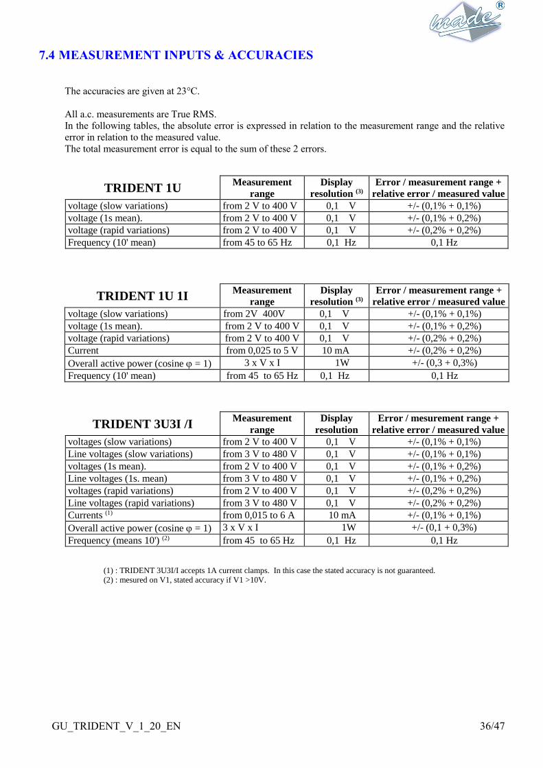
The accuracies are given at 23°C.
All a.c. measurements are True RMS.
In the following tables, the absolute error is expressed in relation to the measurement range and the relative
error in relation to the measured value.
The total measurement error is equal to the sum of these 2 errors.
TRIDENT 1U Measurement
range
Display
resolution (3)
Error / measurement range +
relative error / measured value
voltage (slow variations) from 2 V to 400 V 0,1 V +/- (0,1% + 0,1%)
voltage (1s mean). from 2 V to 400 V 0,1 V +/- (0,1% + 0,2%)
voltage (rapid variations) from 2 V to 400 V 0,1 V +/- (0,2% + 0,2%)
Frequency (10' mean) from 45 to 65 Hz 0,1 Hz 0,1 Hz
TRIDENT 1U 1I Measurement
range
Display
resolution (3)
Error / measurement range +
relative error / measured value
voltage (slow variations) from 2V 400V 0,1 V +/- (0,1% + 0,1%)
voltage (1s mean). from 2 V to 400 V 0,1 V +/- (0,1% + 0,2%)
voltage (rapid variations) from 2 V to 400 V 0,1 V +/- (0,2% + 0,2%)
Current from 0,025 to 5 V 10 mA +/- (0,2% + 0,2%)
Overall active power (cosine = 1) 3 x V x I 1W +/- (0,3 + 0,3%)
Frequency (10' mean) from 45 to 65 Hz 0,1 Hz 0,1 Hz
TRIDENT 3U3I /I Measurement
range
Display
resolution
Error / mesurement range +
relative error / measured value
voltages (slow variations) from 2 V to 400 V 0,1 V +/- (0,1% + 0,1%)
Line voltages (slow variations) from 3 V to 480 V 0,1 V +/- (0,1% + 0,1%)
voltages (1s mean). from 2 V to 400 V 0,1 V +/- (0,1% + 0,2%)
Line voltages (1s. mean) from 3 V to 480 V 0,1 V +/- (0,1% + 0,2%)
voltages (rapid variations) from 2 V to 400 V 0,1 V +/- (0,2% + 0,2%)
Line voltages (rapid variations) from 3 V to 480 V 0,1 V +/- (0,2% + 0,2%)
Currents (1) from 0,015 to 6 A 10 mA +/- (0,1% + 0,1%)
Overall active power (cosine = 1) 3 x V x I 1W +/- (0,1 + 0,3%)
Frequency (means 10') (2) from 45 to 65 Hz 0,1 Hz 0,1 Hz
(1) : TRIDENT 3U3I/I accepts 1A current clamps. In this case the stated accuracy is not guaranteed.
(2) : mesured on V1, stated accuracy if V1 >10V.

GU_TRIDENT_V_1_20_EN 37/47
TRIDENT 3U3I /U Measurement
range
Display
resolution (3)
Error / mesure range + relative
error / measured value
voltages (slow variations) from 2 V to 400 V 0,1 V +/- (0,1% + 0,1%)
Line voltages (slow variations) from 3 V to 480 V 0,1 V +/- (0,1% + 0,1%)
voltages (1s mean). from 2 V to 400 V 0,1 V +/- (0,1% + 0,2%)
Line voltages (1s. mean) from 3 V to 480 V 0,1 V +/- (0,1% + 0,2%)
voltages (rapid variations) from 2 V to 400 V 0,1 V +/- (0,2% + 0,2%)
Line voltages (rapid variations) from 3 V to 480 V 0,1 V +/- (0,2% + 0,2%)
Currents (4) from 0,025 to 5 V 10 mA +/- (0,2% + 0,2%)
Overall active power (cosine = 1) 3 x V x I 1W +/- (0,3 + 0,3%)
Frequency (10' means) (2) from 45 to 65 Hz 0,1 Hz 0,1 Hz
(3) : for the transformation ratios following : TP = 1/1 , TC = 10A/1A (3U3I /I) or 10A/1V (3U3I /U)
(4) : Precision of measurement carried out with a voltage generator having an impedance less than 100. The
measurement precision with current clamps can be degraded. Please consult us for more information on the
recommended clamps.
7.5 STANDARDS
Security regulations :
EN 61010-1, 1993 edition, plus amendement A2 : Règles de sécurité pour appareils électriques de
mesurage, de régulation et de laboratoire.
CEM :
NF EN 50 081-2, décembre1993 : norme générique émission. Partie 2 : environnement industriel.
EN 55 011 : limites et méthodes de mesure des caractéristiques des perturbations électriques des
appareils industriels, scientifiques et médicaux (ISM) to fréquence radioélectrique.
Niveau d'émission : classe A.
Susceptibility to perturbations :
NF EN 50 082-2, juin 1995 : norme générique immunité. Partie 2 : environnement industriel.
EN 61000-4-2, décharges électrostatiques : 4kV au contact.
IEC 1000-4-3, susceptibilité aux champs électromagnétiques : niveau 3 (10V/m).
EN 61000-4-4, transitoires rapides en salves : 1kV sur les entrées/sorties , 2kV sur l'alimentation.
EN 61000-4-6, courant de mode commun en amplitude
EN 61000-4-11, variations lentes de réseaux et micro coupures
EN 61000-4-5, onde de choc (foudre) : 1 kV en différentiel, 2kV en mode commun.
EN 61000-4-12, oscillatoires amorties
GU_TRIDENT_V_1_20_EN 38/47
CHAPTER 8 - HARMONICS : SUPPLEMENT TO THE TRIDENT
USER’S MANUEL
8.1 OVERVIEW OF THE APPLICATION « HARMONICS » FOR TRIDENT
The « HARMONICS » application is a module that enables measurement and monitoring of the harmonic
levels of the three phase electrical network.
This application is loaded in the TRIDENT memory, and coexists with the basic application of TRIDENT :
PERTURBATIONS i. e. the detection of faults and the recording of amplitudes over time.
The change from the PERTURBATIONS application » to the « HARMONICS » application, and vice versa,
is made through the WINTRID software. Refer to its documentation for more details.
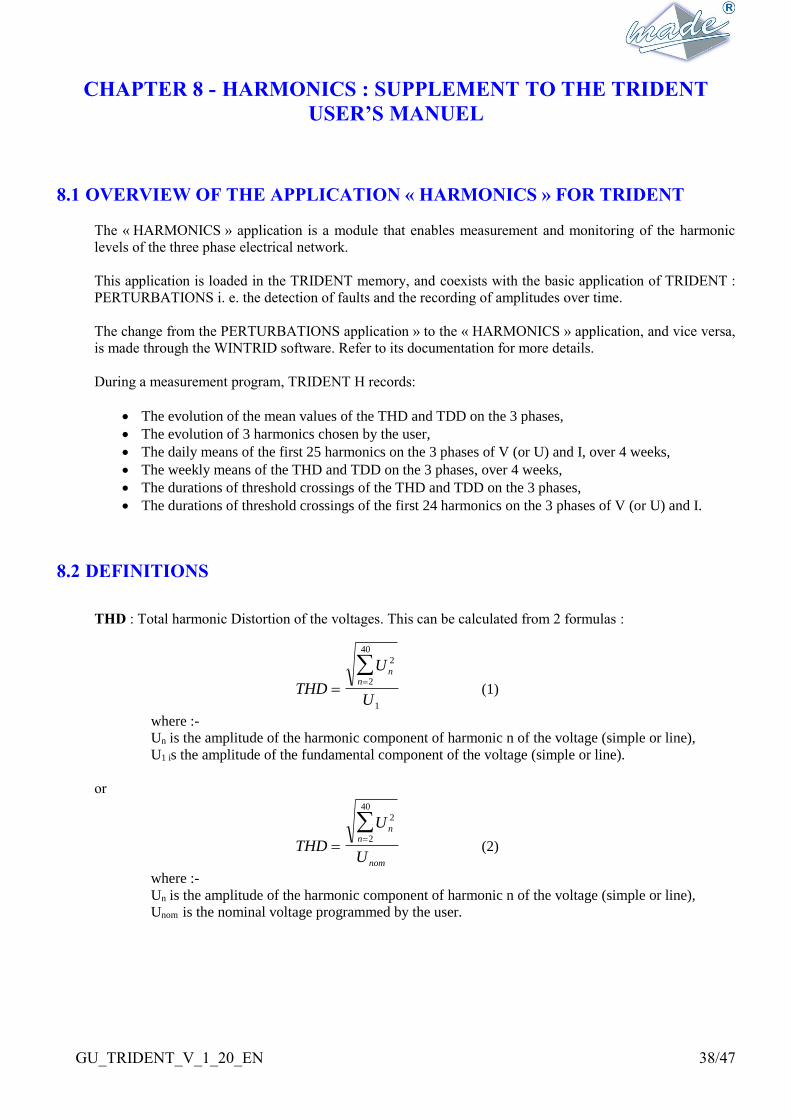
During a measurement program, TRIDENT H records:
The evolution of the mean values of the THD and TDD on the 3 phases,
The evolution of 3 harmonics chosen by the user,
The daily means of the first 25 harmonics on the 3 phases of V (or U) and I, over 4 weeks,
The weekly means of the THD and TDD on the 3 phases, over 4 weeks,
The durations of threshold crossings of the THD and TDD on the 3 phases,
The durations of threshold crossings of the first 24 harmonics on the 3 phases of V (or U) and I.
8.2 DEFINITIONS
THD : Total harmonic Distortion of the voltages. This can be calculated from 2 formulas :
THD
U
U
nn
2
2
40
1
(1)
where :-
Un is the amplitude of the harmonic component of harmonic n of the voltage (simple or line),
U1 is the amplitude of the fundamental component of the voltage (simple or line).
or
THD
U
U
nn
nom
2
2
40
(2)
where :-
Un is the amplitude of the harmonic component of harmonic n of the voltage (simple or line),
Unom is the nominal voltage programmed by the user.

GU_TRIDENT_V_1_20_EN 39/47
TDD : Total harmonic Distortion of the currents. This can be calculated according to 2 formulas :
TDD
I
I
nn
2
2
40
1
(3)
where :-
In is the amplitude of the harmonic component of the harmonic n of the current,
I1 is the amplitude of the fundamental component of the current.
or
TDD
I
I
nn
souscrit
2
2
40
(4)
or
In is the amplitude of the harmonic component of the harmonic n of the current,
Isouscrit is the subscribed current programmed by the user.
Harmonic rate : for each of the harmonic signals measured by TRIDENT H, the harmonic rate is
calculated, according to one or other of the methods below, as selected by the user:
TauxUU
Un
n
no al
min
or TauxUU
Un
n
1
where :-
Un is the amplitude of the harmonic component of harmonic n of the voltage (simple or line),
U1 is the amplitude of the fundamental component of the voltage (simple or line).
Unom is the nominal voltage programmed by the user.
The same formulas are applied to the current measurements.
GU_TRIDENT_V_1_20_EN 40/47
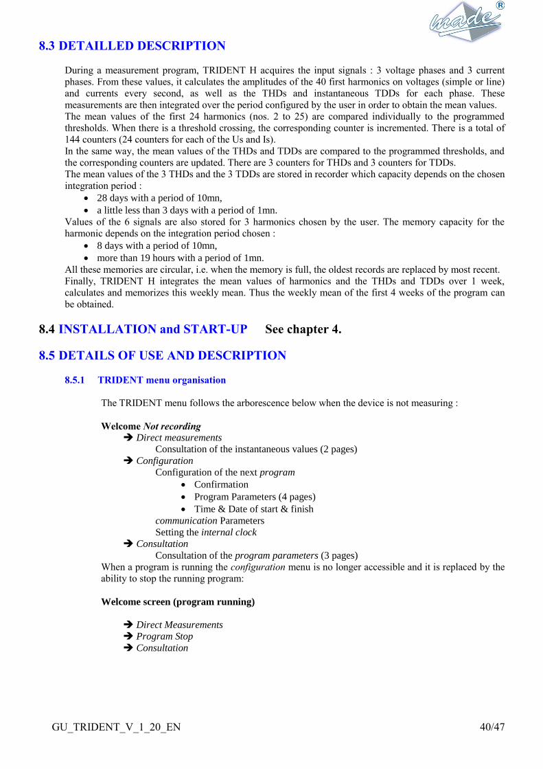
8.3 DETAILLED DESCRIPTION
During a measurement program, TRIDENT H acquires the input signals : 3 voltage phases and 3 current
phases. From these values, it calculates the amplitudes of the 40 first harmonics on voltages (simple or line)
and currents every second, as well as the THDs and instantaneous TDDs for each phase. These
measurements are then integrated over the period configured by the user in order to obtain the mean values.
The mean values of the first 24 harmonics (nos. 2 to 25) are compared individually to the programmed
thresholds. When there is a threshold crossing, the corresponding counter is incremented. There is a total of
144 counters (24 counters for each of the Us and Is).
In the same way, the mean values of the THDs and TDDs are compared to the programmed thresholds, and
the corresponding counters are updated. There are 3 counters for THDs and 3 counters for TDDs.
The mean values of the 3 THDs and the 3 TDDs are stored in recorder which capacity depends on the chosen
integration period :
28 days with a period of 10mn,
a little less than 3 days with a period of 1mn.
Values of the 6 signals are also stored for 3 harmonics chosen by the user. The memory capacity for the
harmonic depends on the integration period chosen :
8 days with a period of 10mn,
more than 19 hours with a period of 1mn.
All these memories are circular, i.e. when the memory is full, the oldest records are replaced by most recent.
Finally, TRIDENT H integrates the mean values of harmonics and the THDs and TDDs over 1 week,
calculates and memorizes this weekly mean. Thus the weekly mean of the first 4 weeks of the program can
be obtained.
8.4 INSTALLATION and START-UP See chapter 4.
8.5 DETAILS OF USE AND DESCRIPTION
8.5.1 TRIDENT menu organisation
The TRIDENT menu follows the arborescence below when the device is not measuring :
Welcome Not recording
Direct measurements
Consultation of the instantaneous values (2 pages)
Configuration
Configuration of the next program
Confirmation
Program Parameters (4 pages)
Time & Date of start & finish
communication Parameters
Setting the internal clock
Consultation
Consultation of the program parameters (3 pages)
When a program is running the configuration menu is no longer accessible and it is replaced by the
ability to stop the running program:
Welcome screen (program running)
Direct Measurements
Program Stop
Consultation

GU_TRIDENT_V_1_20_EN 41/47
8.5.2 Carrying out a measurement program
A) Typical measurement program
See chapter 5.2.
B) TRIDENT H Programming
TRIDENT can be completely programmed using its local interface, in the same way as using
WINTRID.
For this, in the configuration menu, choose Program and validate :
M E N U C O N F I G U R A T I O N
- - > P r o g r a m
C o m M u n I c a t i o n
I n t e r n a l C l o c k
TRIDENT warns you that the last program will be erased permanently from the memory. Check
carefully that this program has been transferred to WINTRID.
A T T E N T I O N ! ! !
T h e p r o g r a m r u n n i n g
w i l l b e s t o p p e d . . .
N O V a l i d a t i o n - >
The +/- keys move between NO & YES, and the VAL key confirms the choice.
Confirm YES to enter the configuration menu.
There are 4 successive pages of configuration. They are all numbered and it is possible to return at
all times to the entries on the previous page with the key.
Choice of the standard configurations :
C O N F I G . P R O G R A M 1 / 4
S t 1 : L I b e l l e 0 1
- - > S t 2 : L I b e l l e 0 2
The user must choose between one of the two standards (of which the name and parameters
have been initialised by the WINTRID software).
The standards contain all the thresholds of the harmonics and the THDs. Their names are those
chosen at the time of their modification in WINTRID.
After having chosen one of the two standards, it is only necessary to enter the types of TC and
VT, the nominal voltage and the times and dates of the start and finish of the program.
GU_TRIDENT_V_1_20_EN 42/47
As delivered, TRIDENT H contains the following two standards:
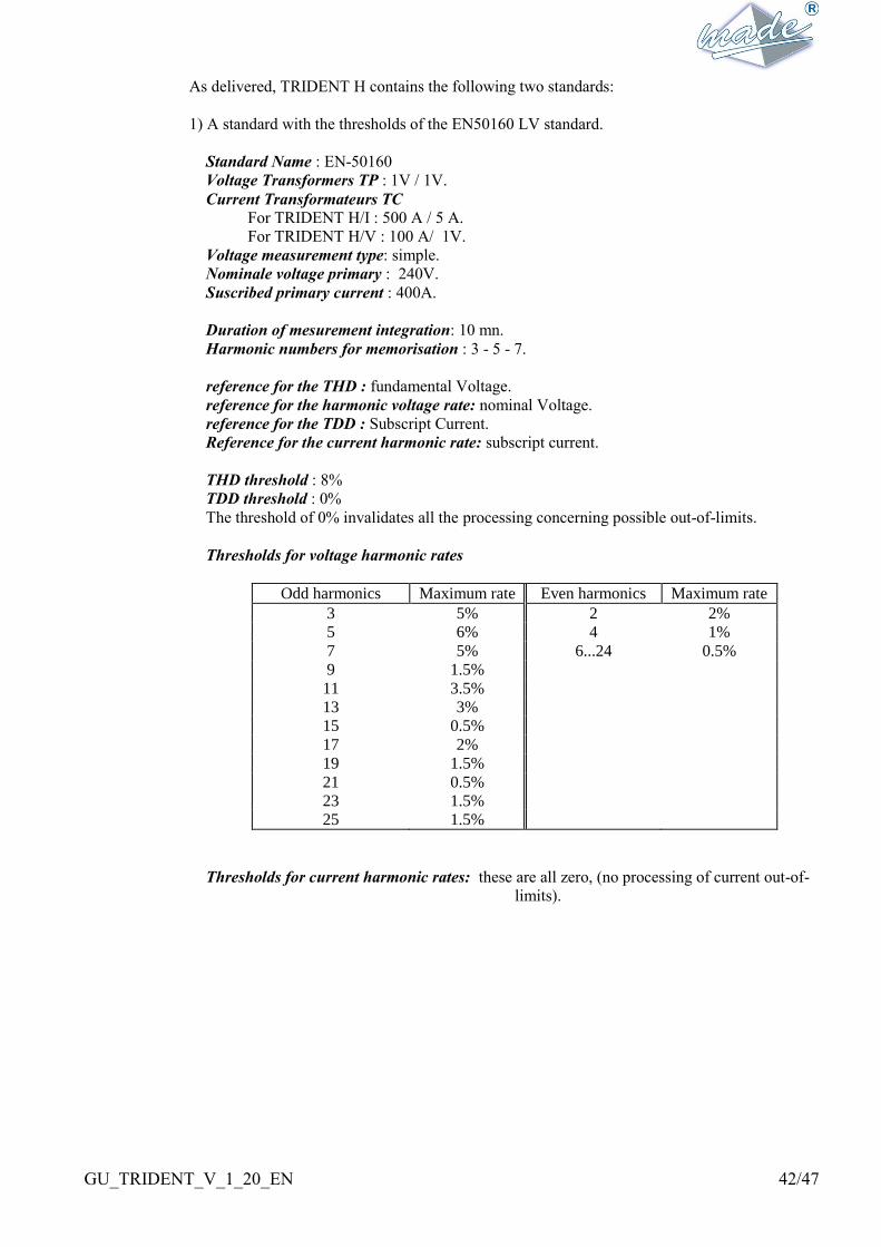
1) A standard with the thresholds of the EN50160 LV standard.
Standard Name : EN-50160
Voltage Transformers TP : 1V / 1V.
Current Transformateurs TC For TRIDENT H/I : 500 A / 5 A.
For TRIDENT H/V : 100 A/ 1V.
Voltage measurement type: simple.
Nominale voltage primary : 240V.
Suscribed primary current : 400A.
Duration of mesurement integration: 10 mn.
Harmonic numbers for memorisation : 3 - 5 - 7.
reference for the THD : fundamental Voltage.
reference for the harmonic voltage rate: nominal Voltage.
reference for the TDD : Subscript Current.
Reference for the current harmonic rate: subscript current.
THD threshold : 8%
TDD threshold : 0%
The threshold of 0% invalidates all the processing concerning possible out-of-limits.
Thresholds for voltage harmonic rates
Odd harmonics Maximum rate Even harmonics Maximum rate
3 5% 2 2%
5 6% 4 1%
7 5% 6...24 0.5%
9 1.5%
11 3.5%
13 3%
15 0.5%
17 2%
19 1.5%
21 0.5%
23 1.5%
25 1.5%
Thresholds for current harmonic rates: these are all zero, (no processing of current out-of-
limits).

GU_TRIDENT_V_1_20_EN 43/47
2) A standard program re-using the thresholds planned for the project of a Standard called
"Emeraude".
Standard name: EMERAUDE A
Voltage transformers TP : 1000V / 100V.
Current transformers TC For TRIDENT H/I : 500 A / 5 A.
For TRIDENT H/V : 100 A/ 1V.
Voltage measurement type: simple.
Nominal primiry voltage : 850V.
Primary subscribed crurent: 500A.
Duration of measurement integration: 10 mn.
Harmoniques numbers for memorisation : 3 - 5 - 7.
Reference for the THD : Nominal voltage.
Reference for the les voltage harmonic rates : Nominal voltage.
Reference for the TDD : Subscript current.
Reference for the current harmonic rates : subscript current.
Threshold of THD : 8%
Threshold of TDD : 8%
Thresholds of the voltage harmonic rates
Odd harmonics Maximum rate Even harmonics Maximum rate
3 5% 2 2%
5 6% 4 1%
7 5% 6...24 0.5%
9 1.5%
11 3.5%
13 3%
15 0.5%
17 2%
19 1.5%
21 0.5%
23 1.5%
25 1.5%
Thresholds of the current harmonic rates
Odd harmonics Maximum rate Even harmonics Maximum rate
3 4% 2 2%
5 6% 4 1%
7 4% 6...24 0.5%
9 2%
11 3%
13 3%
15 2%
17 2%
19 2%
21 2%
23 2%
25 2%
Select one of the two standardsand then validate to go to the 2nd configuration page.

GU_TRIDENT_V_1_20_EN 44/47
Characteristics of the network to be measured :
C O N F I G . P R O G R A M 2 / 4
T V : 2 0 0 0 0 / 1 0 0 . 0 V
C T : 1 0 0 0 A 1 . 0 V
S i m p l e V n = 1 5 0 0 0 . 0 V
H TRIDENT measures directly on the network or via voltage transformers (VT) and current
transformers (TC)
Voltages :
TRIDENT can measure up to 440 VS between phases and between phase and neutral. To
configure the TPs it is necessary to enter or validate values of the primary and the secondary.
The primary can be between 1 and 99999V (no decimal).
The secondary can be between 1 and 999,9V.
NOTE : the transformation ratio is not needed for the earth/neutral voltage.
Currents :
TRIDENT H /I accepts only current clamps with current ouput. It can measure directly up to
6A per phase. To configure the TCs it is necessary to enter or validate values of the primary
and the secondary.
The primary of the TCs can be between 1 and 9999A.
The secondary is 1 or 5A.
TRIDENT H /I is calibrated to measure from 5A inputs. If 1A is chosen, the measurement
precision will be slightly inferior.
TRIDENT H /V accepts only current clamps with voltage output. It can measure directly up
to 5V per phase. To configure the TCs it is necessary to enter or validate values of the
primary and the secondary.
The primary of the TCS can be between 1 and 9999A.
TRIDENT H /V is calibrated to measure from 5V inputs. If a lower value is chosen, the
measurement precision will be slightly inferior.
TRIDENT measures in different modes according to the network selection:
simple (simple voltages) : TRIDENT gives the values of the voltages between phase and
neutral and performs all the event calculations as a function of these values. In the
absence of a neutral, an internal neutral is created by a high impedance resistive bridge.
line (line voltages) : TRIDENT gives the value of the true voltages between phases U12,
U23, U31 and carries out all the event calculations as a function of these values.
Nominal voltage :
This is the nominal voltage for the primary. Its value can be between 50V and 99999,9V and
must be expressed as the voltage between phase and neutral, Vn if simple is selected, and Un if
line voltage is selected.
This value is important because it is the reference for all out-of-limits thresholds.
Note: if the real value is different to the theoretical nominal voltage, it is best to enter the real
value after having consulted the values measured by TRIDENT since its installation.
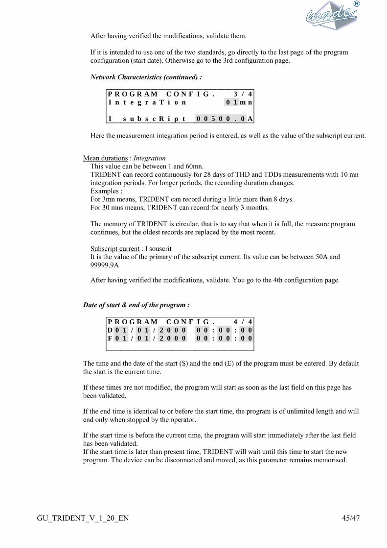
GU_TRIDENT_V_1_20_EN 45/47
After having verified the modifications, validate them.
If it is intended to use one of the two standards, go directly to the last page of the program
configuration (start date). Otherwise go to the 3rd configuration page.
Network Characteristics (continued) :
P R O G R A M C O N F I G . 3 / 4
I n t e g r a T i o n 0 1 m n
I s u b s c R i p t 0 0 5 0 0 . 0 A
Here the measurement integration period is entered, as well as the value of the subscript current.
Mean durations : Integration
This value can be between 1 and 60mn.
TRIDENT can record continuously for 28 days of THD and TDDs measurements with 10 mn
integration periods. For longer periods, the recording duration changes.
Examples :
For 3mn means, TRIDENT can record during a little more than 8 days.
For 30 mns means, TRIDENT can record for nearly 3 months.
The memory of TRIDENT is circular, that is to say that when it is full, the measure program
continues, but the oldest records are replaced by the most recent.
Subscript current : I souscrit
It is the value of the primary of the subscript current. Its value can be between 50A and
99999,9A
After having verified the modifications, validate. You go to the 4th configuration page.
Date of start & end of the program :
P R O G R A M C O N F I G . 4 / 4
D 0 1 / 0 1 / 2 0 0 0 0 0 : 0 0 : 0 0
F 0 1 / 0 1 / 2 0 0 0 0 0 : 0 0 : 0 0
The time and the date of the start (S) and the end (E) of the program must be entered. By default
the start is the current time.
If these times are not modified, the program will start as soon as the last field on this page has
been validated.
If the end time is identical to or before the start time, the program is of unlimited length and will
end only when stopped by the operator.
If the start time is before the current time, the program will start immediately after the last field
has been validated.
If the start time is later than present time, TRIDENT will wait until this time to start the new
program. The device can be disconnected and moved, as this parameter remains memorised.

GU_TRIDENT_V_1_20_EN 46/47
C) Start-up and checking connections
Once plugged in, TRIDENT is started by moving the marche/arrêt switch to the I. position
The red lamp lights and the welcome screen appears. If the measurement program is already
started (if the start time has passed), the welcome screen is different
(voir § Program running).
Pressing the VAL key calls the principal menu.
M A I N M E N U
- D i r e c t M e a s u r e m e n t s
C o n f i g u r a t i o n
C o n s u l t a t i o n
Consult the instantaneous measurements made by TRIDENT in order to check its connections.
For this select the “direct measurements” menu. The following screen appears :
V A L U E S 1 s e c 1 / 2
V 2 3 1 . 1 2 2 8 . 9 2 3 0 . 4
I 0 8 . 7 1 2 . 4 0 4 . 5
There are two successive consultation screens. They are numbered and it is possible to return at
all times to the previous page with the key.
TRIDENT displays measurements averaged over 1 second at the input to device by the
secondaries of the TCs and TPs. These measures are updated every second.
The first page shows:
the 3 simple voltages (or line, according to the configuration) V1, V2, V3 in Volts,
the 3 currents I1, I2, I3 in Amperes,
If the input setting (either voltage or current) TRIDENT H is passed on at least one of the
phases, a warning is shown:
For TRIDENT H /I, if the current on the clamp secondary exceeds 6A :
V A L U E S 1 s e c 1 / 2
V 2 3 1 . 1 2 2 8 . 9 2 3 0 . 4
A l e r t : I m a x = 6 A
For TRIDENT H /U, if the clamp secondary voltage exceeds 6V :
V A L U E S 1 s e c 1 / 2
V 2 3 1 . 1 2 2 8 . 9 2 3 0 . 4
A l e r t : V m a x = 6 V
This warning message disappears with the fault.
The VAL key moves to the 2nd page :
V A L U E S 1 s e c 2 / 2
T H D V 1 4 . 2 3 . 9 0 . 0
T D D I 1 . 0 0 . 7 4 . 1
GU_TRIDENT_V_1_20_EN 47/47
The 2nd page shows:
the THDs in % of the 3 voltages,
the TDDs in % of the 3 currents.
The VAL key returns to the welcome screen.
D) Starting, Stopping, and Ending a measurement program.
see. TRIDENT 3U3I manual.
E) Results of measurement program
In order to analyse the results, it is necessary to transfer the measurements to the P.C. via the series
link using WINTRID.
WINTRID enables the complete transfer of a measure program, whether finished or in progress. In
the second case, WINTRID indicates that the program is not finished and that the end time will be
the time at the transfer; however the program continues to its programmed termination without
change. If there is a voltage fault at the time of transfer, it will not be recorded.
Remark: during the transfer, to accelerate the transmission, the measurement program is
suspended. At the end of the transfer, TRIDENT re-synchronizes itself, before taking new
measurements. This period of no measurement is indicated by WINTRID.
Since the volume of information recorded by TRIDENT H during a measurement program is
considerable, no local consultation of results is available. It is necessary to use WINTRID to
do the analysis of results.
8.5.3 Diverse functions
A) Setting the date & time See notice TRIDENT 3U3I.
B) Access code See notice TRIDENT 3U3I.
8.5.4 Measurement principles of TRIDENT H
The basic cycle of TRIDENT H is one second. The contents of this cycle breakdown as follow:
Sampling the signals V1 (or U12 in voltage line mode) and I1 every 156µs (6400 Hz), this
through two power cycles (40ms),
Calculation of the first 41 harmonics and the THD and TDD for these cycles (these are the 1s
values of TRIDENT H),
Repetition of the 2 previous steps for 2nd and 3rd phases,
update of the intermediate totals,
at the end of the integration period, calculation of the mean values of the harmonics and the
THD/TDD, then update of the memory and the out-of-limits counters.
A) Sampling
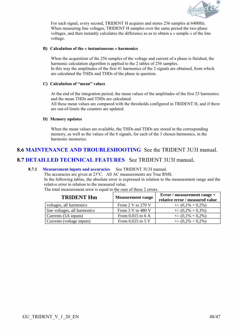
GU_TRIDENT_V_1_20_EN 48/47
For each signal, every second, TRIDENT H acquires and stores 256 samples at 6400Hz.
When measuring line voltages, TRIDENT H samples over the same period the two phase
voltages, and then instantly calculates the difference so as to obtain a « sample » of the line
voltage.
B) Calculation of the « instantaneous » harmonics
When the acquisition of the 256 samples of the voltage and current of a phase is finished, the
harmonic calculation algorithm is applied to the 2 tables of 256 samples.
In this way the amplitudes of the first 41 harmonics of the 2 signals are obtained, from which
are calculated the THDs and TDDs of the phase in question.
C) Calculation of “mean” values
At the end of the integration period, the mean values of the amplitudes of the first 25 harmonics
and the mean THDs and TDDs are calculated.
All these mean values are compared with the thresholds configured in TRIDENT H, and if there
are out-of-limits the counters are updated.
D) Memory updates
When the mean values are available, the THDs and TDDs are stored in the corresponding
memory, as well as the values of the 6 signals, for each of the 3 chosen harmonics, in the
harmonic memories.
8.6 MAINTENANCE AND TROUBLESHOOTING See the TRIDENT 3U3I manual.
8.7 DETAILLED TECHNICAL FEATURES See TRIDENT 3U3I manual.
8.7.1 Measurement inputs and accuracies See TRIDENT 3U3I manual.
The accuracies are given at 23°C. All AC measurements are True RMS.
In the following tables, the absolute error is expressed in relation to the measurement range and the
relative error in relation to the measured value.
The total measurement error is equal to the sum of these 2 errors.
TRIDENT Hm Measurement range Error / measurement range +
relative error / measured value
voltages, all harmonics From 2 V to 270 V +/- (0,1% + 0,2%)
line voltages, all harmonics From 3 V to 480 V +/- (0,2% + 0,3%)
Currents (5A inputs) From 0,015 to 6 A +/- (0,1% + 0,2%)
Currents (voltage inputs) From 0,025 to 5 V +/- (0,2% + 0,2%)