TRAUB TNL12 / TNL12K - CNC swiss and non-swiss turning ...€¦ · programming, editing, setup and...
12
CNC swiss and non-swiss turning center TNL12K TNL12
Transcript of TRAUB TNL12 / TNL12K - CNC swiss and non-swiss turning ...€¦ · programming, editing, setup and...

CNC swiss and non-swiss
turning center
TNL12K
TNL12

The machine concept of the
TNL12 has been matched
to the daily re quire ments of
the user. But this is not all.
In addition, it offers a large
number of advantages:
Simultaneous and independent
machining of up to 4 tool carriers
for highly productive mach in ing in
a single clamping setup
2 independent working levels
(patented) ensure absence of
collisions
Optimum operating ergonomics
provided by the work area accessi-
ble on both sides
Hydraulic hollow clamping
cylinders for main spindle and
counter spindle
Guide bushings freely
selectable: fixed, synchronously
running or programmable
TNL12 - Ideal for your
production requirements
The independent Z2 axis
Flexibility
Productivity
Process safety
Z3
Z2
Z1
2

3
2 tool turrets
Containing 6 stations each (tool
drive possible, stations can be
fitted with 2 tools)
Chip-to-chip time 0.3 seconds
separate Z axis for tool turret
top
Y axis for tool turret bottom
Front working attachment
With 4 stations
Tool drive possible for all
stations
3 stations can be fitted with 2
tools each
Separate Z axis
Backworking attachment
With 4 stations
Tool drive possible for all
stations
3 stations can be fitted with
2 tools each
Separate X axis
Up to 4 tool carriers
for your flexibility
The central clamping screw
Tool holder change
in just 30 seconds
The central clamping screw
allows you to set up each
station in no time
Repeating accuracy
+/- 0.01 mm
Powerful tool drive
Max. 1.5 kW
On all stations
Compact inclined bed of high
torsional and bending stiffness at
a 60 degree inclination for unre-
stricted chip fall
Standard thermocompen sation
provides lasting precision
Small amount of space
re quired for the machine groups
through compact machine dimen-
sions suited to the room size

Headstock max. bar capacity 13/16 mm (0.5/0.6 inch) • • • •Z1 storke max. 130 mm (5.1 inch)
Counter spindle max. bar capacity 13/16 mm (0.5/0.6 inch) • • • •Z4 storke max. 139 mm (5.5 inch)
Turret 1 Stations 6 (12) • • • • • Drive possible
Turret 2 Stations 6 (12) • •Drive possible
Front working attachment Stations 4 (7) • • •Drive possible
Backworking attachment Stations 4 (7) • •Drive possible
Number of subsystemsfor simultaneous independent machining 2 1 2 3 4
Number of CNC linear axes 5 4 6 7 9
Tool stock 10 6 12 14 20
Tool stock max. 19 12 24 26 38
Machinable 5 sides 6 sides 6 sides 6 sides 6 sides
Relative machining time
Y1
X1Y1
X1
Z4
C4
Z1
C1
Z1
C1
Z3
X3
4

5
Headstock max. bar capacity 13/16 mm (0.5/0.6 inch) • • • •Z1 storke max. 130 mm (5.1 inch)
Counter spindle max. bar capacity 13/16 mm (0.5/0.6 inch) • • • •Z4 storke max. 139 mm (5.5 inch)
Turret 1 Stations 6 (12) • • • • • Drive possible
Turret 2 Stations 6 (12) • •Drive possible
Front working attachment Stations 4 (7) • • •Drive possible
Backworking attachment Stations 4 (7) • •Drive possible
Number of subsystemsfor simultaneous independent machining 2 1 2 3 4
Number of CNC linear axes 5 4 6 7 9
Tool stock 10 6 12 14 20
Tool stock max. 19 12 24 26 38
Machinable 5 sides 6 sides 6 sides 6 sides 6 sides
Relative machining time
Options -as varied as
your requirements
Double tool holder,
fi xed or driven
X4
Z2
X2
Z3Z4
X3
Y1
X1
Z1
C4
C1
Z3Z4
X3 C4
Z1
C1X4
Y1
X1
Z1
C1
Z2
X2
Y1
X1Z4
C4

Thread whirling on turret 2:
Max. material ø 5.5 mm (ø 0.2 inch)
Max. thread length 38 mm (1.5 inch)
Thread whirling with front working attachment:
Max. material ø 10 mm (ø 0.4 inch)
Max. thread length 110 mm (4.3 inch)
High-frequency machining (inside) on front working/
backworking attachment:
Max. speed 35,000 rpm (80,000 rpm)
Gear cutting on turret 1:
Straight toothing
Max. module 0.6
Deep hole drilling on front working/backworking
attachment:
Max. coolant injection pressure 120 (160) bar
Min. drill ø 0.7 mm (ø 0.03 inch)
Max. drilling depth approx. 100 mm (3.9 inch)
ZX
S
C
Z
X
C
S
S workpiece
S tool
Z
6
(only TNL12K)
X
C
Z
Y
S

7
The best choice for a wide
range of parts

CNC control
Ergonomic interactive user interface for
programming, editing, setup and operation
Graphics-supported interactive guidance
also during setup
Comfortable process synchronization and
optimization of the program sequences of
parallel machining processes
Visual verification to avoid collision
situations through graphical process simulation
Highly sensitive tool breakage monitoring
Large 15” display
Tool monitoring
Highly sensitive tool breakage and tool
wear monitoring
No additional sensors required
Easy to use, for example, through automatic
generation of limiting curves
Live monitoring:
Any deviations of the actual monitoring from
the learning curve are displayed live
(Option)
8

9
Additional safety device –
Electronic quick retraction
Active on all TRAUB machines
Minimization of machine damage
Active counter control in case of malfunction
Response time in the millisecond range by
intelligent servo amplifier
More effective than mechanical safety
systems
Programming, Optimization, Simulation
Realistic real-time simulation for shorter
setup times
Standard 3-D control of workpiece
geometry
Control of the working sequences
Visual collision control before the machine
is run in
(standard)
External programming
TRAUB WinFlexIPSPlus (option)
Step-by-step parallel programming and
simulation possible
Extremely easy synchronization of machining
sequences of up to 4 sub-systems
Cycle-time optimization already during
programming
Planning and optimization of the setup
operation using “Manual mode” and “Automatic
mode” functions corresponding to the real
machine
TRAUB TX8i-s
The fast control
for good workpieces
Electronic quick retraction
Response time < 1 ms

One machine model -
twice the range of parts
whether swiss and non-swiss turning
center, the machine concept is the
same:
TNL12 swiss turning center
TNL12K non-swiss turning center
Your advantage:
You use the same tool holders
Identical programming on both
machines, thus no additional training
required
Unique in its kind:
using one machine concept for
the CNC swiss and non-swiss turning center
Swiss turning center Non swiss turning center
10
11
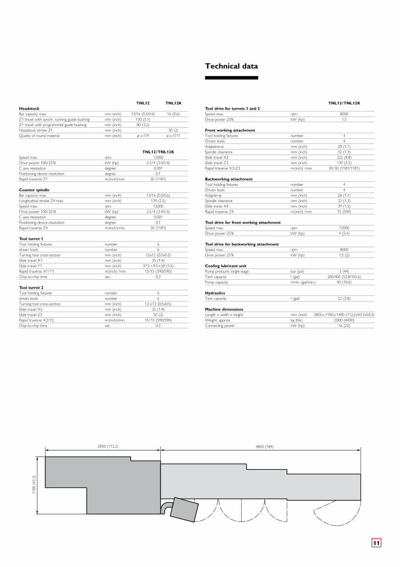
TNL12 TNL12K Headstock Bar capacity max. mm (inch) 13/16 (0.5/0.6) 16 (0.6) Z1 travel with synchr. running guide bushing mm (inch) 130 (5.1) Z1 travel with programmed guide bushing mm (inch) 80 (3.2) Headstock stroke Z1 mm (inch) 50 (2) Quality of round material mm (inch) ø x IT9 ø x IT11
TNL12/TNL12KSpeed max. rpm 12000 Drive power 100/25% kW (hp) 2.5/4 (3.4/5.4) C axis resolution degree 0.001 Positioning device resolution degree 0.1 Rapid traverse Z1 m(inch)/min. 30 (1181)
Counter spindle Bar capacity max. mm (inch) 13/16 (0.5/0.6) Longitudinal stroke Z4 max. mm (inch) 139 (5.5) Speed max. rpm 12000 Drive power 100/25 % kW (hp) 2.5/4 (3.4/5.4) C axis resolution degree 0.001 Positioning device resolution degree 0.1 Rapid traverse Z4 m(inch)/min. 30 (1181)
Tool turret 1 Tool holding fixtures number 6 driven tools number 6 Turning tool cross-section mm (inch) 12x12 (0.5x0.5) Slide travel X1 mm (inch) 35 (1.4) Slide travel Y1 mm (inch) 37.5 /-9,5+28 (1.5) Rapid traverse X1/Y1 m(inch) /min. 15/15 (590/590) Chip-to-chip time sec. 0.3
Tool turret 2 Tool holding fixtures number 6 driven tools number 6 Turning tool cross-section mm (inch) 12 x 12 (0.5x0.5) Slide travel X2 mm (inch) 35 (1.4) Slide travel Z2 mm (inch) 50 (2) Rapid traverse X2/Y2 m(inch)/min. 15/15 (590/590) Chip-to-chip time sec. 0.3
TNL12/TNL12KTool drive for turrets 1 and 2 Speed max. rpm 8000 Drive power 25% kW (hp) 1.5
Front working attachment Tool holding fixtures number 4 Driven tools number 4 Adaptere-ø mm (inch) 28 (1.1) Spindle clearance mm (inch) 32 (1.3) Slide travel X3 mm (inch) 222 (8.8) Slide travel Z3 mm (inch) 139 (5.5) Rapid traverse X3/Z3 m(inch) /min. 30/30 (1181/1181)
Backworking attachment Tool holding fixtures number 4 Driven tools number 4 Adapter-ø mm (inch) 28 (1.1) Spindle clearance mm (inch) 32 (1.3) Slide travel X4 mm (inch) 39 (1.5) Rapid traverse Z4 m(inch) /min. 15 (590)
Tool drive for front working attachment Speed max. rpm 12000 Drive power 25% kW (hp) 4 (5.4)
Tool drive for backworking attachment Speed max. rpm 8000 Drive power 25% kW (hp) 1.5 (2)
Cooling lubricant unit Pump pressure, single-stage bar (psi) 3 (44) Tank capacity l (gal) 200/400 (52.8/105.6) Pump capacity l/min. (gal/min.) 40 (10.6)
Hydraulics Tank capacity l (gal) 22 (5.8)
Machine dimensions Length x width x height mm (inch) 2850 x 1100 x 1480 (112.2x43.3x58.3)Weight, approx. kg (lbs) 2000 (4400) Connecting power kW (hp) 16 (22)
4800 (189)2850 (112.2)
1100
(43
.3)
Technical data

03.1
5 –
800/
1 KS
Su
bjec
t to
cha
nge
with
out
prio
r no
tice
TRAUB Drehmaschinen
GmbH & Co. KG
Hauffstraße 4
73262 Reichenbach, Germany
Phone +49 (0) 7153 502-0
Fax +49 (0) 7153) 502-694
www.traub.de