
TRANSMISSION/TRANSAXLE AT A B SECTION
332
AT-1 TRANSMISSION/TRANSAXLE D E F G H I J K L M SECTION AT A B AT N O P CONTENTS AUTOMATIC TRANSMISSION SERVICE INFORMATION ........................... 5 INDEX FOR DTC ................................................ 5 Alphabetical Index .................................................... 5 DTC No. Index ......................................................... 5 PRECAUTIONS .................................................. 7 Precaution for Supplemental Restraint System (SRS) "AIR BAG" and "SEAT BELT PRE-TEN- SIONER" .................................................................. 7 Precaution for On Board Diagnosis (OBD) System of A/T and Engine .................................................... 7 Precaution ................................................................ 7 Service Notice or Precaution .................................... 8 PREPARATION .................................................. 9 Special Service Tool ................................................ 9 Commercial Service Tool ......................................... 9 A/T FLUID ..........................................................11 Changing A/T Fluid ................................................ 11 Checking A/T Fluid ................................................. 11 A/T Fluid Cooler Cleaning ...................................... 13 A/T CONTROL SYSTEM ...................................16 Cross-Sectional View (2WD Models) ..................... 16 Cross-Sectional View (VQ35DE Models for AWD) .... 17 Cross-Sectional View (VK45DE Models for AWD) .... 18 Shift Mechanism ..................................................... 18 TCM Function ......................................................... 29 CAN Communication .............................................. 30 Input/Output Signal of TCM .................................... 31 Line Pressure Control ............................................ 31 Shift Control ........................................................... 33 Lock-up Control ...................................................... 34 Engine Brake Control ............................................. 35 Control Valve .......................................................... 36 ON BOARD DIAGNOSTIC (OBD) SYSTEM .....38 Introduction ............................................................ 38 OBD-II Function for A/T System ............................. 38 One or Two Trip Detection Logic of OBD-II ........... 38 OBD-II Diagnostic Trouble Code (DTC) .................38 Malfunction Indicator Lamp (MIL) ...........................40 TROUBLE DIAGNOSIS .................................... 41 DTC Inspection Priority Chart .................................41 Fail-Safe .................................................................41 How to Perform Trouble Diagnosis for Quick and Accurate Repair ......................................................42 A/T Electrical Parts Location ..................................48 Circuit Diagram .......................................................49 Inspections Before Trouble Diagnosis ....................49 Road Test ...............................................................53 Vehicle Speed at Which Gear Shifting Occurs .......58 Vehicle Speed at Which Lock-up Occurs/Releas- es ............................................................................58 Symptom Chart .......................................................59 TCM Input/Output Signal Reference Value ............83 CONSULT-III Function (TRANSMISSION) .............84 Diagnosis Procedure without CONSULT-III ...........91 DTC U1000 CAN COMMUNICATION LINE ..... 94 Description ..............................................................94 On Board Diagnosis Logic ......................................94 Possible Cause .......................................................94 DTC Confirmation Procedure .................................94 Wiring Diagram - AT - CAN ....................................95 Diagnosis Procedure ..............................................96 DTC P0615 START SIGNAL CIRCUIT ............. 97 Description ..............................................................97 CONSULT-III Reference Value in Data Monitor Mode .......................................................................97 On Board Diagnosis Logic ......................................97 Possible Cause .......................................................97 DTC Confirmation Procedure .................................97 Wiring Diagram - AT - STSIG .................................98 Diagnosis Procedure ..............................................99 DTC P0700 TCM ............................................. 101 Description ............................................................ 101 On Board Diagnosis Logic .................................... 101 Revision: 2007 April 2008 FX35/FX45
Transcript of TRANSMISSION/TRANSAXLE AT A B SECTION
TRANSMISSION/TRANSAXLE
D
E
SECTION ATA
B
T
AAUTOMATIC TRANSMISSIONF
G
H
I
J
K
L
M
N
O
P
CONTENTS
SERVICE INFORMATION ............................ 5
INDEX FOR DTC ................................................. 5Alphabetical Index .....................................................5DTC No. Index ..........................................................5
PRECAUTIONS ................................................... 7Precaution for Supplemental Restraint System (SRS) "AIR BAG" and "SEAT BELT PRE-TEN-SIONER" ...................................................................7Precaution for On Board Diagnosis (OBD) System of A/T and Engine .....................................................7Precaution .................................................................7Service Notice or Precaution .....................................8
PREPARATION ................................................... 9Special Service Tool .................................................9Commercial Service Tool ..........................................9
A/T FLUID ...........................................................11Changing A/T Fluid .................................................11Checking A/T Fluid ..................................................11A/T Fluid Cooler Cleaning .......................................13
A/T CONTROL SYSTEM ....................................16Cross-Sectional View (2WD Models) ......................16Cross-Sectional View (VQ35DE Models for AWD) ....17Cross-Sectional View (VK45DE Models for AWD) ....18Shift Mechanism ......................................................18TCM Function ..........................................................29CAN Communication ...............................................30Input/Output Signal of TCM .....................................31Line Pressure Control .............................................31Shift Control ............................................................33Lock-up Control .......................................................34Engine Brake Control ..............................................35Control Valve ...........................................................36
ON BOARD DIAGNOSTIC (OBD) SYSTEM ......38Introduction .............................................................38OBD-II Function for A/T System ..............................38One or Two Trip Detection Logic of OBD-II ............38
OBD-II Diagnostic Trouble Code (DTC) ..................38Malfunction Indicator Lamp (MIL) ............................40
TROUBLE DIAGNOSIS ....................................41DTC Inspection Priority Chart ..................................41Fail-Safe ..................................................................41How to Perform Trouble Diagnosis for Quick and Accurate Repair .......................................................42A/T Electrical Parts Location ...................................48Circuit Diagram ........................................................49Inspections Before Trouble Diagnosis .....................49Road Test ................................................................53Vehicle Speed at Which Gear Shifting Occurs ........58Vehicle Speed at Which Lock-up Occurs/Releas-es .............................................................................58Symptom Chart ........................................................59TCM Input/Output Signal Reference Value .............83CONSULT-III Function (TRANSMISSION) ..............84Diagnosis Procedure without CONSULT-III ............91
DTC U1000 CAN COMMUNICATION LINE .....94Description ...............................................................94On Board Diagnosis Logic .......................................94Possible Cause ........................................................94DTC Confirmation Procedure ..................................94Wiring Diagram - AT - CAN .....................................95Diagnosis Procedure ...............................................96
DTC P0615 START SIGNAL CIRCUIT .............97Description ...............................................................97CONSULT-III Reference Value in Data Monitor Mode ........................................................................97On Board Diagnosis Logic .......................................97Possible Cause ........................................................97DTC Confirmation Procedure ..................................97Wiring Diagram - AT - STSIG ..................................98Diagnosis Procedure ...............................................99
DTC P0700 TCM ............................................. 101Description .............................................................101On Board Diagnosis Logic .....................................101
AT-1Revision: 2007 April 2008 FX35/FX45

Possible Cause ......................................................101DTC Confirmation Procedure ................................101Diagnosis Procedure .............................................101
DTC P0705 PARK/NEUTRAL POSITION SWITCH ........................................................... 102
Description .............................................................102CONSULT-III Reference Value in Data Monitor Mode ......................................................................102On Board Diagnosis Logic .....................................102Possible Cause ......................................................102DTC Confirmation Procedure ................................102Wiring Diagram - AT - PNP/SW .............................103Diagnosis Procedure .............................................103
DTC P0717 TURBINE REVOLUTION SEN-SOR .................................................................. 106
Description .............................................................106CONSULT-III Reference Value in Data Monitor Mode ......................................................................106On Board Diagnosis Logic .....................................106Possible Cause ......................................................106DTC Confirmation Procedure ................................106Diagnosis Procedure .............................................106
DTC P0720 VEHICLE SPEED SENSOR A/T (REVOLUTION SENSOR) ............................... 108
Description .............................................................108CONSULT-III Reference Value in Data Monitor Mode ......................................................................108On Board Diagnosis Logic .....................................108Possible Cause ......................................................108DTC Confirmation Procedure ................................108Wiring Diagram - AT - VSSA/T ..............................109Diagnosis Procedure .............................................110
DTC P0725 ENGINE SPEED SIGNAL ............ 112Description .............................................................112CONSULT-III Reference Value in Data Monitor Mode ......................................................................112On Board Diagnosis Logic .....................................112Possible Cause ......................................................112DTC Confirmation Procedure ................................112Diagnosis Procedure .............................................112
DTC P0731 A/T 1ST GEAR FUNCTION ......... 114Description .............................................................114On Board Diagnosis Logic .....................................114Possible Cause ......................................................114DTC Confirmation Procedure ................................114Diagnosis Procedure .............................................115
DTC P0732 A/T 2ND GEAR FUNCTION ......... 116Description .............................................................116On Board Diagnosis Logic .....................................116Possible Cause ......................................................116DTC Confirmation Procedure ................................116Diagnosis Procedure .............................................117
DTC P0733 A/T 3RD GEAR FUNCTION .........118Description ............................................................ 118On Board Diagnosis Logic .................................... 118Possible Cause ..................................................... 118DTC Confirmation Procedure ................................ 118Diagnosis Procedure ............................................. 119
DTC P0734 A/T 4TH GEAR FUNCTION ..........120Description ............................................................ 120On Board Diagnosis Logic .................................... 120Possible Cause ..................................................... 120DTC Confirmation Procedure ................................ 120Diagnosis Procedure ............................................. 121
DTC P0735 A/T 5TH GEAR FUNCTION ..........122Description ............................................................ 122On Board Diagnosis Logic .................................... 122Possible Cause ..................................................... 122DTC Confirmation Procedure ................................ 122Diagnosis Procedure ............................................. 123
DTC P0740 TORQUE CONVERTER CLUTCH SOLENOID VALVE ..........................................124
Description ............................................................ 124CONSULT-III Reference Value in Data Monitor Mode ..................................................................... 124On Board Diagnosis Logic .................................... 124Possible Cause ..................................................... 124DTC Confirmation Procedure ................................ 124Diagnosis Procedure ............................................. 124
DTC P0744 A/T TCC S/V FUNCTION (LOCK-UP) ....................................................................126
Description ............................................................ 126CONSULT-III Reference Value in Data Monitor Mode ..................................................................... 126On Board Diagnosis Logic .................................... 126Possible Cause ..................................................... 126DTC Confirmation Procedure ................................ 126Diagnosis Procedure ............................................. 126
DTC P0745 LINE PRESSURE SOLENOID VALVE ..............................................................128
Description ............................................................ 128CONSULT-III Reference Value in Data Monitor Mode ..................................................................... 128On Board Diagnosis Logic .................................... 128Possible Cause ..................................................... 128DTC Confirmation Procedure ................................ 128Diagnosis Procedure ............................................. 128
DTC P1705 THROTTLE POSITION SENSOR ..130Description ............................................................ 130CONSULT-III Reference Value in Data Monitor Mode ..................................................................... 130On Board Diagnosis Logic .................................... 130Possible Cause ..................................................... 130DTC Confirmation Procedure ................................ 130Diagnosis Procedure ............................................. 130
AT-2Revision: 2007 April 2008 FX35/FX45

D
E
F
G
H
I
J
K
L
M
A
B
T
N
O
P
N
A
DTC P1710 A/T FLUID TEMPERATURE SEN-SOR CIRCUIT ................................................... 132
Description ............................................................ 132CONSULT-III Reference Value in Data Monitor Mode ..................................................................... 132On Board Diagnosis Logic .................................... 132Possible Cause ..................................................... 132DTC Confirmation Procedure ................................ 132Wiring Diagram - AT - FTS .................................... 133Diagnosis Procedure ............................................. 133Component Inspection .......................................... 135
DTC P1721 VEHICLE SPEED SENSOR MTR ..137Description ............................................................ 137CONSULT-III Reference Value in Data Monitor Mode ..................................................................... 137On Board Diagnosis Logic .................................... 137Possible Cause ..................................................... 137DTC Confirmation Procedure ................................ 137Diagnosis Procedure ............................................. 137
DTC P1730 A/T INTERLOCK .......................... 139Description ............................................................ 139On Board Diagnosis Logic .................................... 139Possible Cause ..................................................... 139DTC Confirmation Procedure ................................ 139Judgement of A/T Interlock ................................... 139Diagnosis Procedure ............................................. 139
DTC P1731 A/T 1ST ENGINE BRAKING ........ 141Description ............................................................ 141CONSULT-III Reference Value in Data Monitor Mode ..................................................................... 141On Board Diagnosis Logic .................................... 141Possible Cause ..................................................... 141DTC Confirmation Procedure ................................ 141Diagnosis Procedure ............................................. 141
DTC P1752 INPUT CLUTCH SOLENOID VALVE .............................................................. 143
Description ............................................................ 143CONSULT-III Reference Value in Data Monitor Mode ..................................................................... 143On Board Diagnosis Logic .................................... 143Possible Cause ..................................................... 143DTC Confirmation Procedure ................................ 143Diagnosis Procedure ............................................. 143
DTC P1757 FRONT BRAKE SOLENOID VALVE .............................................................. 145
Description ............................................................ 145CONSULT-III Reference Value in Data Monitor Mode ..................................................................... 145On Board Diagnosis Logic .................................... 145Possible Cause ..................................................... 145DTC Confirmation Procedure ................................ 145Diagnosis Procedure ............................................. 145
DTC P1762 DIRECT CLUTCH SOLENOID VALVE .............................................................. 147
Description .............................................................147CONSULT-III Reference Value in Data Monitor Mode ......................................................................147On Board Diagnosis Logic .....................................147Possible Cause ......................................................147DTC Confirmation Procedure ................................147Diagnosis Procedure .............................................147
DTC P1767 HIGH AND LOW REVERSE CLUTCH SOLENOID VALVE ......................... 149
Description .............................................................149CONSULT-III Reference Value in Data Monitor Mode ......................................................................149On Board Diagnosis Logic .....................................149Possible Cause ......................................................149DTC Confirmation Procedure ................................149Diagnosis Procedure .............................................149
DTC P1772 LOW COAST BRAKE SOLENOID VALVE ............................................................. 151
Description .............................................................151CONSULT-III Reference Value in Data Monitor Mode ......................................................................151On Board Diagnosis Logic .....................................151Possible Cause ......................................................151DTC Confirmation Procedure ................................151Diagnosis Procedure .............................................151
DTC P1774 LOW COAST BRAKE SOLENOID VALVE FUNCTION ......................................... 153
Description .............................................................153CONSULT-III Reference Value in Data Monitor Mode ......................................................................153On Board Diagnosis Logic .....................................153Possible Cause ......................................................153DTC Confirmation Procedure ................................153Diagnosis Procedure .............................................153
DTC P1815 MANUAL MODE SWITCH .......... 155Description .............................................................155CONSULT-III Reference Value in Data Monitor Mode ......................................................................155On Board Diagnosis Logic .....................................155Possible Cause ......................................................155DTC Confirmation Procedure ................................155Wiring Diagram - AT - MMSW ...............................156Diagnosis Procedure .............................................158Component Inspection ...........................................159
MAIN POWER SUPPLY AND GROUND CIR-CUIT ................................................................ 160
Wiring Diagram - AT - MAIN ..................................160Diagnosis Procedure .............................................161
CLOSED THROTTLE POSITION AND WIDE OPEN THROTTLE POSITION CIRCUIT ......... 164
CONSULT-III Reference Value in Data Monitor Mode ......................................................................164Diagnosis Procedure .............................................164
AT-3Revision: 2007 April 2008 FX35/FX45

BRAKE SIGNAL CIRCUIT .............................. 165CONSULT-III Reference Value in Data Monitor Mode ......................................................................165Diagnosis Procedure .............................................165
A/T INDICATOR CIRCUIT ............................... 166Description .............................................................166CONSULT-III Reference Value in Data Monitor Mode ......................................................................166Diagnosis Procedure .............................................166
TROUBLE DIAGNOSIS FOR SYMPTOMS ..... 167Wiring Diagram - AT - NONDTC ............................167A/T Check Indicator Lamp Does Not Come On .....170Engine Cannot Be Started in "P" or "N" Position ...170In "P" Position, Vehicle Moves When Pushed .......171In "N" Position, Vehicle Moves ..............................172Large Shock ("N" to "D" Position) ..........................173Vehicle Does Not Creep Backward in "R" Position ..175Vehicle Does Not Creep Forward in "D" Position ..178Vehicle Cannot Be Started from D1 .......................180A/T Does Not Shift: D1→ D2 ..................................182A/T Does Not Shift: D2→ D3 ..................................184A/T Does Not Shift: D3→ D4 ..................................186A/T Does Not Shift: D4→ D5 ..................................188A/T Does Not Lock-up ...........................................190A/T Does Not Hold Lock-up Condition ...................192Lock-up Is Not Released .......................................194Engine Speed Does Not Return to Idle .................194Cannot Be Changed to Manual Mode ...................195A/T Does Not Shift: 5th Gear → 4th Gear .............196A/T Does Not Shift: 4th Gear → 3rd Gear .............197A/T Does Not Shift: 3rd Gear → 2nd Gear ............199A/T Does Not Shift: 2nd Gear → 1st Gear .............201Vehicle Does Not Decelerate by Engine Brake .....202
SHIFT CONTROL SYSTEM ............................ 205Control Device Removal and Installation ...............205Control Rod Removal and Installation ...................206Adjustment of A/T Position ....................................207Checking of A/T Position .......................................207
A/T SHIFT LOCK SYSTEM ............................. 208Description .............................................................208Shift Lock System Electrical Parts Location ..........208Wiring Diagram - AT - SHIFT .................................209Diagnosis Procedure .............................................209
KEY INTERLOCK CABLE ............................... 212Component ............................................................212Removal and Installation .......................................212
ON-VEHICLE SERVICE ...................................215Control Valve with TCM and A/T Fluid Tempera-ture Sensor 2 ........................................................ 215Parking Component (2WD Models Only) .............. 226Rear Oil Seal ......................................................... 233Revolution Sensor Component (2WD Models Only) ..................................................................... 233
AIR BREATHER HOSE ....................................239Removal and Installation ....................................... 239
TRANSMISSION ASSEMBLY ..........................241Removal and Installation (2WD Models) ............... 241Removal and Installation (AWD Models) .............. 243
OVERHAUL ......................................................249Component ........................................................... 249Oil Channel ........................................................... 261Location of Adjusting Shims, Needle Bearings, Thrust Washers and Snap Rings .......................... 264
DISASSEMBLY ................................................267Disassembly .......................................................... 267
REPAIR FOR COMPONENT PARTS ..............285Oil Pump ............................................................... 285Front Sun Gear, 3rd One-Way Clutch ................... 287Front Carrier, Input Clutch, Rear Internal Gear ..... 289Mid Sun Gear, Rear Sun Gear, High and Low Re-verse Clutch Hub .................................................. 295High and Low Reverse Clutch .............................. 301Direct Clutch ......................................................... 303
ASSEMBLY ......................................................306Assembly (1) ......................................................... 306Adjustment ............................................................ 320Assembly (2) ......................................................... 323
SERVICE DATA AND SPECIFICATIONS (SDS) ................................................................330
General Specification ............................................ 330Vehicle Speed at Which Gear Shifting Occurs ..... 330Vehicle Speed at Which Lock-up Occurs/Releas-es .......................................................................... 331Stall Speed ............................................................ 331Line Pressure ........................................................ 331A/T Fluid Temperature Sensor .............................. 332Turbine Revolution Sensor ................................... 332Vehicle Speed Sensor A/T (Revolution Sensor) ... 332Reverse Brake ...................................................... 332Total End Play ....................................................... 332
AT-4Revision: 2007 April 2008 FX35/FX45

INDEX FOR DTC
D
E
F
G
H
I
J
K
L
M
A
B
T
N
O
P
< SERVICE INFORMATION >
A
SERVICE INFORMATIONINDEX FOR DTC
Alphabetical Index INFOID:0000000001327120
NOTE:If “DTC U1000” is displayed with other DTCs, first perform the trouble diagnosis for “DTC U1000 CANCOMMUNICATION”. Refer to AT-94.
*1: These numbers are prescribed by SAE J2012.
*2: These malfunctions cannot be displayed MIL if another malfunction is assigned to MIL.
DTC No. Index INFOID:0000000001327121
NOTE:If “DTC U1000” is displayed with other DTCs, first perform the trouble diagnosis for “DTC U1000 CANCOMMUNICATION”. Refer to AT-94.
Items(CONSULT-III screen terms)
DTC
Reference pageOBD-II Except OBD-II
CONSULT-III
GST(*1) CONSULT-III only “TRANS-
MISSION”
A/T 1ST E/BRAKING — P1731 AT-141
ATF 1ST GR FNCTN P0731 P0731 AT-114
ATF 2ND GR FNCTN P0732 P0732 AT-116
ATF 3RD GR FNCTN P0733 P0733 AT-118
ATF 4TH GR FNCTN P0734 P0734 AT-120
ATF 5TH GR FNCTN P0735 P0735 AT-122
A/T INTERLOCK P1730 P1730 AT-139
A/T TCC S/V FNCTN P0744(*2) P0744 AT-126
ATF TEMP SEN/CIRC P0710 P1710 AT-132
CAN COMM CIRCUIT U1000 U1000 AT-94
D/C SOLENOID/CIRC P1762 P1762 AT-147
ENGINE SPEED SIG P0725 P0725 AT-112
FR/B SOLENOID/CIRC P1757 P1757 AT-145
HLR/C SOL/CIRC P1767 P1767 AT-149
I/C SOLENOID/CIRC P1752 P1752 AT-143
L/PRESS SOL/CIRC P0745 P0745 AT-128
LC/B SOLENOID/CIRC P1772 P1772 AT-151
LC/B SOLENOID FNCT P1774(*2) P1774 AT-153
MANU MODE SW/CIRC — P1815 AT-155
PNP SW/CIRC P0705 P0705 AT-102
STARTER RELAY/CIRC — P0615 AT-97
TCC SOLENOID/CIRC P0740 P0740 AT-124
TCM P0700 P0700 AT-101
TP SEN/CIRC A/T P1705 P1705 AT-130
TURBINE REV S/CIRC P0717 P0717 AT-106
VEH SPD SE/CIR-MTR — P1721 AT-137
VEH SPD SEN/CIR AT P0720 P0720 AT-108
AT-5Revision: 2007 April 2008 FX35/FX45

INDEX FOR DTC
< SERVICE INFORMATION >*1: These numbers are prescribed by SAE J2012.
*2: These malfunctions cannot be displayed MIL if another malfunction is assigned to MIL.
DTC
Items(CONSULT-III screen terms)
Reference pageOBD-II Except OBD-II
CONSULT-III
GST(*1)
CONSULT-III only “TRANSMIS-
SION”
— P0615 STARTER RELAY/CIRC AT-97
P0700 P0700 TCM AT-101
P0705 P0705 PNP SW/CIRC AT-102
P0710 P1710 ATF TEMP SEN/CIRC AT-132
P0717 P0717 TURBINE REV S/CIRC AT-106
P0720 P0720 VEH SPD SEN/CIR AT AT-108
P0725 P0725 ENGINE SPEED SIG AT-112
P0731 P0731 A/T 1ST GR FNCTN AT-114
P0732 P0732 A/T 2ND GR FNCTN AT-116
P0733 P0733 A/T 3RD GR FNCTN AT-118
P0734 P0734 A/T 4TH GR FNCTN AT-120
P0735 P0735 A/T 5TH GR FNCTN AT-122
P0740 P0740 TCC SOLENOID/CIRC AT-124
P0744(*2) P0744 A/T TCC S/V FNCTN AT-126
P0745 P0745 L/PRESS SOL/CIRC AT-128
P1705 P1705 TP SEN/CIRC A/T AT-130
— P1721 VEH SPD SE/CIR-MTR AT-137
P1730 P1730 A/T INTERLOCK AT-139
— P1731 A/T 1ST E/BRAKING AT-141
P1752 P1752 I/C SOLENOID/CIRC AT-143
P1757 P1757 FR/B SOLENOID/CIRC AT-145
P1762 P1762 D/C SOLENOID/CIRC AT-147
P1767 P1767 HLR/C SOL/CIRC AT-149
P1772 P1772 LC/B SOLENOID/CIRC AT-151
P1774(*2) P1774 LC/B SOLENOID FNCT AT-153
— P1815 MANU MODE SW/CIRC AT-155
U1000 U1000 CAN COMM CIRCUIT AT-94
AT-6Revision: 2007 April 2008 FX35/FX45

PRECAUTIONS
D
E
F
G
H
I
J
K
L
M
A
B
T
N
O
P
< SERVICE INFORMATION >
A
PRECAUTIONS
Precaution for Supplemental Restraint System (SRS) "AIR BAG" and "SEAT BELT PRE-TENSIONER" INFOID:0000000001612925
The Supplemental Restraint System such as “AIR BAG” and “SEAT BELT PRE-TENSIONER”, used alongwith a front seat belt, helps to reduce the risk or severity of injury to the driver and front passenger for certaintypes of collision. This system includes seat belt switch inputs and dual stage front air bag modules. The SRSsystem uses the seat belt switches to determine the front air bag deployment, and may only deploy one frontair bag, depending on the severity of a collision and whether the front occupants are belted or unbelted.Information necessary to service the system safely is included in the “SUPPLEMENTAL RESTRAINT SYS-TEM” and “SEAT BELTS” of this Service Manual.WARNING:• To avoid rendering the SRS inoperative, which could increase the risk of personal injury or death in
the event of a collision which would result in air bag inflation, all maintenance must be performed byan authorized NISSAN/INFINITI dealer.
• Improper maintenance, including incorrect removal and installation of the SRS, can lead to personalinjury caused by unintentional activation of the system. For removal of Spiral Cable and Air BagModule, see the “SUPPLEMENTAL RESTRAINT SYSTEM”.
• Do not use electrical test equipment on any circuit related to the SRS unless instructed to in thisService Manual. SRS wiring harnesses can be identified by yellow and/or orange harnesses or har-ness connectors.
Precaution for On Board Diagnosis (OBD) System of A/T and Engine INFOID:0000000001327123
The ECM has an on board diagnostic system. It will light up the malfunction indicator lamp (MIL) to warn thedriver of a malfunction causing emission deterioration.CAUTION:• Be sure to turn the ignition switch OFF and disconnect the battery cable from the negative terminal
before any repair or inspection work. The open/short circuit of related switches, sensors, solenoidvalves, etc. Will cause the MIL to light up.
• Be sure to connect and lock the connectors securely after work. A loose (unlocked) connector willcause the MIL to light up due to an open circuit. (Be sure the connector is free from water, grease,dirt, bent terminals, etc.)
• Be sure to route and secure the harnesses properly after work. Interference of the harness with abracket, etc. May cause the MIL to light up due to a short circuit.
• Be sure to connect rubber tubes properly after work. A misconnected or disconnected rubber tubemay cause the MIL to light up due to a malfunction of the EVAP system or fuel injection system, etc.
• Be sure to erase the unnecessary malfunction information (repairs completed) from the TCM andECM before returning the vehicle to the customer.
Precaution INFOID:0000000001327124
• Before connecting or disconnecting the A/T assembly har-ness connector, turn ignition switch OFF and disconnect thebattery cable from the negative terminal. Because batteryvoltage is applied to TCM even if ignition switch is turnedOFF.
SEF289H
AT-7Revision: 2007 April 2008 FX35/FX45

PRECAUTIONS
< SERVICE INFORMATION >• After performing each TROUBLE DIAGNOSIS, perform “DTC(Diagnostic Trouble Code) Confirmation Procedure”.If the repair is completed the DTC should not be displayed inthe “DTC Confirmation Procedure”.
• Always use the specified brand of ATF. Refer to MA-9, "Fluids and Lubricants".• Use lint-free paper not cloth rags during work.• After replacing the ATF, dispose of the waste oil using the methods prescribed by law, ordinance, etc.• Before proceeding with disassembly, thoroughly clean the outside of the transmission. It is important to pre-
vent the internal parts from becoming contaminated by dirt or other foreign matter.• Disassembly should be done in a clean work area.• Use lint-free paper or towels for wiping parts clean. Common shop rags can leave fibers that could interfere
with the operation of the transmission.• Place disassembled parts in order for easier and proper assembly.• All parts should be carefully cleansed with a general purpose, non-flammable solvent before inspection or
reassembly.• Gaskets, seals and O-rings should be replaced any time the transmission is disassembled.• It is very important to perform functional tests whenever they are indicated.• The valve body contains precision parts and requires extreme care when parts are removed and serviced.
Place disassembled valve body parts in order for easier and proper assembly. Care will also prevent springsand small parts from becoming scattered or lost.
• Properly installed valves, sleeves, plugs, etc. will slide along bores in valve body under their own weight.• Before assembly, apply a coat of recommended ATF to all parts. Apply petroleum jelly to protect O-rings and
seals, or hold bearings and washers in place during assembly. Do not use grease.• Extreme care should be taken to avoid damage to O-rings, seals and gaskets when assembling.• After overhaul, refill the transmission with new ATF.• When the A/T drain plug is removed, only some of the ATF is drained. Old ATF will remain in torque con-
verter and ATF cooling system.Always follow the procedures under “Changing A/T Fluid” in the AT section when changing A/T fluid. Refer toAT-11, "Changing A/T Fluid", AT-11, "Checking A/T Fluid".
Service Notice or Precaution INFOID:0000000001327125
ATF COOLER SERVICEIf ATF contains frictional material (clutches, bands, etc.), or if an A/T is repaired, overhauled, or replaced,inspect and clean the A/T fluid cooler mounted in the radiator or replace the radiator. Flush cooler lines usingcleaning solvent and compressed air after repair. For A/T fluid cooler cleaning procedure, refer to AT-13, "A/TFluid Cooler Cleaning". For radiator replacement, refer to CO-13 (for VQ35DE), CO-40 (for VK45DE).
OBD-II SELF-DIAGNOSIS• A/T self-diagnosis is performed by the TCM in combination with the ECM. The results can be read through
the blinking pattern of the A/T CHECK indicator or the malfunction indicator lamp (MIL). Refer to the table onAT-84, "CONSULT-III Function (TRANSMISSION)" for the indicator used to display each self-diagnosticresult.
• The self-diagnostic results indicated by the MIL are automatically stored in both the ECM and TCM memo-ries.Always perform the procedure on AT-38, "OBD-II Diagnostic Trouble Code (DTC)" to complete therepair and avoid unnecessary blinking of the MIL.
For details of OBD-II, refer to EC-54 (for VQ35DE) or EC-632 (for VK45DE).• Certain systems and components, especially those related to OBD, may use the new style slide-lock-
ing type harness connector. For description and how to disconnect, refer to PG-68.
SEF217U
AT-8Revision: 2007 April 2008 FX35/FX45

PREPARATION
D
E
F
G
H
I
J
K
L
M
A
B
T
N
O
P
< SERVICE INFORMATION >
A
PREPARATION
Special Service Tool INFOID:0000000001327126
The actual shapes of Kent-Moore tools may differ from those of special service tools illustrated here.
Commercial Service Tool INFOID:0000000001327127
Tool number(Kent-Moore No.)Tool name
Description
ST2505S001(J-34301-C)Oil pressure gauge set1. ST25051001( — )Oil pressure gauge2. ST25052000( — )Hose3. ST25053000( — )Joint pipe4. ST25054000( — )Adapter5. ST25055000( — )Adapter
Measuring line pressure
KV31103600(J-45674)Joint pipe adapter(With ST25054000)
Measuring line pressure
ST33400001(J-26082)Drifta: 60 mm (2.36 in) dia.b: 47 mm (1.85 in) dia.
• Installing rear oil seal (2WD models)• Installing oil pump housing oil seal
KV31102400(J-34285 and J-34285-87)Clutch spring compressora: 320 mm (12.60 in)b: 174 mm (6.85 in)
Installing reverse brake return spring retainer
ST25850000(J-25721-A)Sliding hammera: 179 mm (7.05 in)b: 70 mm (2.76 in)c: 40 mm (1.57 in) dia.d: M12X1.75P
Removing oil pump assembly
SCIA3695J
ZZA1227D
NT086
NT423
NT422
AT-9Revision: 2007 April 2008 FX35/FX45

PREPARATION
< SERVICE INFORMATION >Tool name Description
Power tool Loosening bolts and nuts
Drifta: 22 mm (0.87 in) dia.
Installing manual shaft oil seals
Drifta: 64 mm (2.52 in) dia.
Installing rear oil seal (AWD models)
PBIC0190E
NT083
SCIA5338E
AT-10Revision: 2007 April 2008 FX35/FX45

A/T FLUID
D
E
F
G
H
I
J
K
L
M
A
B
T
N
O
P
< SERVICE INFORMATION >
A
A/T FLUID
Changing A/T Fluid INFOID:0000000001327128
1. Warm up ATF.2. Stop engine.3. Loosen the level gauge bolt.4. Drain ATF from drain plug and refill with new ATF. Always refill
same volume with drained ATF.• To replace the ATF, pour in new ATF at the A/T fluid charging
pipe with the engine idling, at the same time drain the old ATFfrom the radiator cooler hose return side.
• When the color of the ATF coming out is almost same as thecolor of the new ATF, the replacement is complete. Theamount of new ATF to use should be 30 to 50% increase ofthe stipulated amount.
CAUTION:• Use only Genuine NISSAN Matic J ATF. Do not mix with other ATF.• Using ATF other than Genuine NISSAN Matic J ATF will cause deterioration in driveability and A/
T durability, and may damage the A/T, which is not covered by the warranty.• When filling ATF, take care not to scatter heat generating parts such as exhaust.• Do not reuse drain plug gasket.
5. Run engine at idle speed for 5 minutes.6. Check A/T fluid level and condition. Refer to AT-11, "Checking A/T Fluid". If ATF is still dirty, repeat step 2.
through 5.7. Install the removed A/T fluid level gauge into A/T fluid charging pipe.8. Tighten the level gauge bolt.
Checking A/T Fluid INFOID:0000000001327129
1. Warm up engine.2. Check for A/T fluid leakage.3. Loosen the level gauge bolt.4. Before driving, A/T fluid level can be checked at A/T fluid tem-
peratures of 30 to 50°C (86 to 122°F) using “COLD” range on A/T fluid level gauge as follows.
a. Park vehicle on level surface and set parking brake.b. Start engine and move selector lever through each gear posi-
tion. Leave selector lever in “P” position.c. Check A/T fluid level with engine idling.d. Remove A/T fluid level gauge and wipe clean with lint-free
paper.CAUTION:
ATF: Genuine NISSAN Matic J ATF
Fluid capacity: 10.3 (10-7/8 US qt, 9-1/8 lmp qt)
Drain plug:: 34 N·m (3.5 kg-m, 25 ft-lb)
Level gauge bolt:: 5.1 N·m (0.52 kg-m, 45 in-lb)
SCIA4896E
SCIA7120E
AT-11Revision: 2007 April 2008 FX35/FX45

A/T FLUID
< SERVICE INFORMATION >When wiping away the A/T fluid level gauge, always use lint-free paper, not a cloth one.e. Re-insert A/T fluid level gauge into A/T fluid charging pipe as far as it will go.
CAUTION:To check A/T fluid level, insert the A/T fluid level gauge until the cap contacts the end of the A/Tfluid charging pipe, with the A/T fluid level gauge reversed from the normal attachment conditions.
f. Remove A/T fluid level gauge and note reading. If reading is at low side of range, add ATF to the A/T fluidcharging pipe.CAUTION:Do not overfill.
5. Drive vehicle for approximately 5 minutes in urban areas.6. Make the A/T fluid temperature approximately 65°C (149°F).
NOTE:A/T fluid level will be greatly affected by temperature as shown in figure. Therefore, be certain toperform operation while checking data with CONSULT-III.
a. Connect CONSULT-III to data link connector.b. Select “MAIN SIGNALS” in “DATA MONITOR” mode for “TRANSMISSION” with CONSULT-III.c. Read out the value of “ATF TEMP 1”.7. Recheck A/T fluid level at A/T fluid temperatures of approximately 65°C (149°F) using “HOT” range on A/
T fluid level gauge.CAUTION:• When wiping away the A/T fluid level gauge, always use lint-free paper, not a cloth one.• To check A/T fluid level, insert the A/T fluid level gauge
until the cap contacts the end of the A/T fluid chargingpipe, with the A/T fluid level gauge reversed from the nor-mal attachment conditions as shown.
8. Check A/T fluid condition.• If ATF is very dark or smells burned, check operation of A/T.
Flush cooling system after repair of A/T.• If ATF contains frictional material (clutches, bands, etc.),
replace radiator and flush cooler line using cleaning solventand compressed air after repair of A/T. Refer to CO-13 (forVQ35DE) or CO-40 (for VK45DE) and AT-13, "A/T FluidCooler Cleaning".
SLIA0016E
SCIA2899E
AT-12Revision: 2007 April 2008 FX35/FX45

A/T FLUID
D
E
F
G
H
I
J
K
L
M
A
B
T
N
O
P
< SERVICE INFORMATION >
A
9. Install the removed A/T fluid level gauge in the A/T fluid chargingpipe.
10. Tighten level gauge bolt.
A/T Fluid Cooler Cleaning INFOID:0000000001327130
Whenever an A/T is replaced, the A/T fluid cooler mounted in the radiator must be inspected and cleaned.Metal debris and friction material, if present, can become trapped in the A/T fluid cooler. This debris can con-taminate the newly serviced A/T or, in severe cases, can block or restrict the flow of ATF. In either case, mal-function of the newly serviced A/T may result.Debris, if present, may build up as ATF enters the cooler inlet. It will be necessary to back flush the coolerthrough the cooler outlet in order to flush out any built up debris.
A/T FLUID COOLER CLEANING PROCEDURE1. Position an oil pan under the A/T's inlet and outlet cooler hoses.2. Identify the inlet and outlet A/T fluid cooler hoses.3. Disconnect the A/T fluid cooler inlet and outlet rubber hoses
from the steel cooler tubes or bypass valve.NOTE:Replace the cooler hoses if rubber material from the hoseremains on the tube fitting.
4. Allow any ATF that remains in the cooler hoses to drain into theoil pan.
5. Insert the extension adapter hose of a can of TransmissionCooler Cleaner (Nissan P/N 999MP-AM006) into the cooler out-let hose.CAUTION:• Wear safety glasses and rubber gloves when spraying the
Transmission Cooler Cleaner.• Spray Transmission Cooler Cleaner only with adequate
ventilation.• Avoid contact with eyes and skin.• Do not breath vapors or spray mist.
6. Hold the hose and can as high as possible and spray Transmis-sion Cooler Cleaner in a continuous stream into the cooler outlethose until ATF flows out of the cooler inlet hose for 5 seconds.
Level gauge bolt:: 5.1 N·m (0.52 kg-m, 45 in-lb)
SCIA4896E
SCIA3830E
SCIA3831E
AT-13Revision: 2007 April 2008 FX35/FX45

A/T FLUID
< SERVICE INFORMATION >7. Insert the tip of an air gun into the end of the cooler outlet hose.8. Wrap a shop rag around the air gun tip and of the cooler outlethose.
9. Blow compressed air regulated to 5 to 9 kg/cm2 (70 to 130 psi)through the cooler outlet hose for 10 seconds to force out anyremaining ATF.
10. Repeat steps 5 through 9 three additional times.11. Position an oil pan under the banjo bolts that connect the A/T
fluid cooler steel lines to the A/T.12. Remove the banjo bolts.13. Flush each steel line from the cooler side back toward the A/T
by spraying Transmission Cooler Cleaner in a continuous stream for 5 seconds.
14. Blow compressed air regulated to 5 to 9 kg/cm2 (70 to 130 psi) through each steel line from the coolerside back toward the transmission for 10 seconds to force out any remaining ATF.
15. Ensure all debris is removed from the steel cooler lines.16. Ensure all debris is removed from the banjo bolts and fittings.17. Perform "A/T FLUID COOLER DIAGNOSIS PROCEDURE".
A/T FLUID COOLER DIAGNOSIS PROCEDURENOTE:Insufficient cleaning of the cooler inlet hose exterior may lead to inaccurate debris identification.1. Position an oil pan under the A/T's inlet and outlet cooler hoses.2. Clean the exterior and tip of the cooler inlet hose.3. Insert the extension adapter hose of a can of Transmission
Cooler Cleaner (Nissan P/N 999MP-AM006) into the cooler out-let hose.CAUTION:• Wear safety glasses and rubber gloves when spraying the
Transmission Cooler Cleaner.• Spray Transmission Cooler Cleaner only with adequate
ventilation.• Avoid contact with eyes and skin.• Do not breath vapors or spray mist.
4. Hold the hose and can as high as possible and spray Transmis-sion Cooler Cleaner in a continuous stream into the cooler outlethose until ATF flows out of the cooler inlet hose for 5 seconds.
5. Tie a common white, basket-type coffee filter to the end of thecooler inlet hose.
SCIA3832E
SCIA3831E
SCIA3833E
AT-14Revision: 2007 April 2008 FX35/FX45

A/T FLUID
D
E
F
G
H
I
J
K
L
M
A
B
T
N
O
P
< SERVICE INFORMATION >
A
6. Insert the tip of an air gun into the end of the cooler outlet hose.7. Wrap a shop rag around the air gun tip and end of cooler outlet
hose.
8. Blow compressed air regulated to 5 to 9 kg/cm2 (70 to 130 psi)through the cooler outlet hose to force any remaining ATF intothe coffee filter.
9. Remove the coffee filter from the end of the cooler inlet hose.10. Perform "A/T FLUID COOLER INSPECTION PROCEDURE".
A/T FLUID COOLER INSPECTION PROCEDURE1. Inspect the coffee filter for debris.a. If small metal debris less than 1 mm (0.040 in) in size or metal
powder is found in the coffee filter, this is normal. If normaldebris is found, the A/T fluid cooler/radiator can be re-used andthe procedure is ended.
b. If one or more pieces of debris are found that are over 1 mm(0.040 in) in size and/or peeled clutch facing material is found inthe coffee filter, the fluid cooler is not serviceable. The A/T fluidcooler/radiator must be replaced and the inspection procedure isended. Refer to CO-13 and CO-16 (for VQ35DE), CO-40 andCO-44 (for VK45DE).
A/T FLUID COOLER FINAL INSPECTIONAfter performing all procedures, ensure that all remaining oil is cleaned from all components.
SCIA3834E
SCIA2967E
SCIA7031E
AT-15Revision: 2007 April 2008 FX35/FX45

A/T CONTROL SYSTEM
< SERVICE INFORMATION >A/T CONTROL SYSTEM
Cross-Sectional View (2WD Models) INFOID:0000000001327131
1. Front planetary gear 2. Mid planetary gear 3. Rear planetary gear
4. Direct clutch 5. High and low reverse clutch 6. Reverse brake
7. Drum support 8. Forward brake 9. Low coast brake
10. Input shaft 11. Torque converter 12. Oil pump
13. Front brake 14. 3rd one-way clutch 15. Input clutch
16. 1st one-way clutch 17. Control valve with TCM 18. Forward one-way clutch
19. Rear extension 20. Output shaft
SCIA5262E
AT-16Revision: 2007 April 2008 FX35/FX45

A/T CONTROL SYSTEM
D
E
F
G
H
I
J
K
L
M
A
B
T
N
O
P
< SERVICE INFORMATION >
A
Cross-Sectional View (VQ35DE Models for AWD) INFOID:0000000001327132
1. Front planetary gear 2. Mid planetary gear 3. Rear planetary gear
4. Direct clutch 5. High and low reverse clutch 6. Reverse brake
7. Drum support 8. Forward brake 9. Low coast brake
10. Input shaft 11. Torque converter 12. Oil pump
13. Front brake 14. 3rd one-way clutch 15. Input clutch
16. 1st one-way clutch 17. Control valve with TCM 18. Forward one-way clutch
19. Adapter case 20. Output shaft
SCIA5263E
AT-17Revision: 2007 April 2008 FX35/FX45

A/T CONTROL SYSTEM
< SERVICE INFORMATION >Cross-Sectional View (VK45DE Models for AWD) INFOID:0000000001327133
Shift Mechanism INFOID:0000000001327134
The A/T uses compact triple planetary gear systems to improve power transmission efficiency, simplify con-struction and reduce weight.It also employs an optimum shift control and super wide gear ratios. They improve starting performance andacceleration during medium and high-speed operation.
CONSTRUCTION
1. Front planetary gear 2. Mid planetary gear 3. Rear planetary gear
4. Direct clutch 5. High and low reverse clutch 6. Reverse brake
7. Drum support 8. Forward brake 9. Low coast brake
10. Input shaft 11. Torque converter 12. Oil pump
13. Front brake 14. 3rd one-way clutch 15. Input clutch
16. 1st one-way clutch 17. Control valve with TCM 18. Forward one-way clutch
19. Adapter case 20. Output shaft
SCIA5268E
AT-18Revision: 2007 April 2008 FX35/FX45

A/T CONTROL SYSTEM
D
E
F
G
H
I
J
K
L
M
A
B
T
N
O
P
< SERVICE INFORMATION >
A
FUNCTION OF CLUTCH AND BRAKE
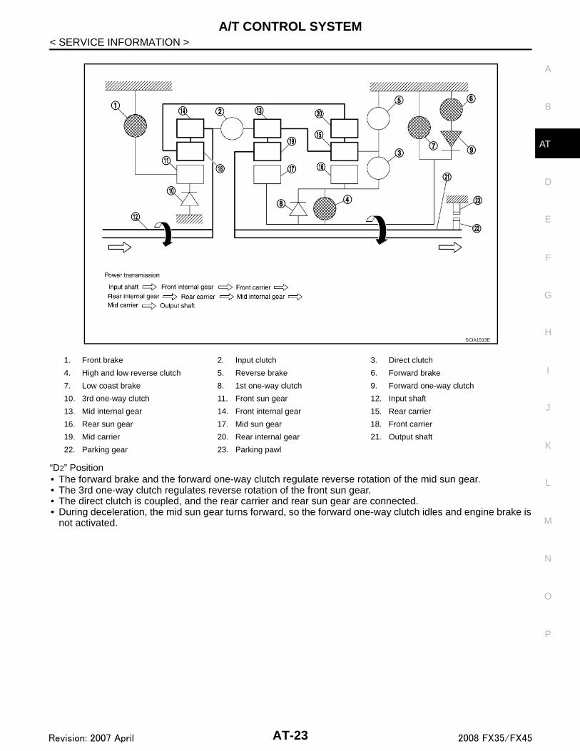
1. Front brake 2. Input clutch 3. Direct clutch
4. High and low reverse clutch 5. Reverse brake 6. Forward brake
7. Low coast brake 8. 1st one-way clutch 9. Forward one-way clutch
10. 3rd one-way clutch 11. Front sun gear 12. Input shaft
13. Mid internal gear 14. Front internal gear 15. Rear carrier
16. Rear sun gear 17. Mid sun gear 18. Front carrier
19. Mid carrier 20. Rear internal gear 21. Output shaft
22. Parking gear 23. Parking pawl
PCIA0002J
Name of the Part Abbreviation Function
Front brake (1) FR/B Fastens the front sun gear (11).
Input clutch (2) I/CConnects the input shaft (12), the front internal gear (14) and the mid internal gear (13).
Direct clutch (3) D/C Connects the rear carrier (15) and the rear sun gear (16).
High and low reverse clutch (4) HLR/C Connects the mid sun gear (17) and the rear sun gear (16).
Reverse brake (5) R/B Fastens the rear carrier (15).
Forward brake (6) Fwd/B Fastens the mid sun gear (17).
Low coast brake (7) LC/B Fastens the mid sun gear (17).
1st one-way clutch (8) 1st OWCAllows the rear sun gear (16) to turn freely forward relative to the mid sun gear (17) but fastens it for reverse rotation.
Forward one-way clutch (9) Fwd OWCAllows the mid sun gear (17) to turn freely in the forward direction but fastens it for reverse rotation.
3rd one-way clutch (10) 3rd OWCAllows the front sun gear (11) to turn freely in the forward direction but fastens it for reverse rotation.
AT-19Revision: 2007 April 2008 FX35/FX45

A/T CONTROL SYSTEM
< SERVICE INFORMATION >CLUTCH AND BAND CHART
POWER TRANSMISSION
“N” PositionSince both the forward brake and the reverse brake are released, torque from the input shaft drive is not trans-mitted to the output shaft.
“P” Position
SCIA6962E
AT-20Revision: 2007 April 2008 FX35/FX45

A/T CONTROL SYSTEM
D
E
F
G
H
I
J
K
L
M
A
B
T
N
O
P
< SERVICE INFORMATION >
A
• The same as for the “N” position, both the forward brake and the reverse brake are released, so torque fromthe input shaft drive is not transmitted to the output shaft.
• The parking pawl linked with the selector lever meshes with the parking gear and fastens the output shaftmechanically.
“D1” Position• The forward brake and the forward one-way clutch regulate reverse rotation of the mid sun gear.• The 1st one-way clutch regulates reverse rotation of the rear sun gear.• The 3rd one-way clutch regulates reverse rotation of the front sun gear.• During deceleration, the mid sun gear turns forward, so the forward one-way clutch idles and the engine
brake is not activated.
1. Front brake 2. Input clutch 3. Direct clutch
4. High and low reverse clutch 5. Reverse brake 6. Forward brake
7. Low coast brake 8. 1st one-way clutch 9. Forward one-way clutch
10. 3rd one-way clutch 11. Front sun gear 12. Input shaft
13. Mid internal gear 14. Front internal gear 15. Rear carrier
16. Rear sun gear 17. Mid sun gear 18. Front carrier
19. Mid carrier 20. Rear internal gear 21. Output shaft
22. Parking gear 23. Parking pawl
PCIA0003J
AT-21Revision: 2007 April 2008 FX35/FX45

A/T CONTROL SYSTEM
< SERVICE INFORMATION >“M1” Position• The front brake fastens the front sun gear.• The forward brake and the forward one-way clutch regulate reverse rotation of the mid sun gear.• High and low reverse clutch connects the rear sun gear and the mid sun gear.• The low coast brake fastens the mid sun gear.• During deceleration, the low coast brake regulates forward rotation of the mid sun gear and the engine brake
functions.
1. Front brake 2. Input clutch 3. Direct clutch
4. High and low reverse clutch 5. Reverse brake 6. Forward brake
7. Low coast brake 8. 1st one-way clutch 9. Forward one-way clutch
10. 3rd one-way clutch 11. Front sun gear 12. Input shaft
13. Mid internal gear 14. Front internal gear 15. Rear carrier
16. Rear sun gear 17. Mid sun gear 18. Front carrier
19. Mid carrier 20. Rear internal gear 21. Output shaft
22. Parking gear 23. Parking pawl
SCIA1512E
AT-22Revision: 2007 April 2008 FX35/FX45
A/T CONTROL SYSTEM
D
E
F
G
H
I
J
K
L
M
A
B
T
N
O
P
< SERVICE INFORMATION >
A
“D2” Position• The forward brake and the forward one-way clutch regulate reverse rotation of the mid sun gear.• The 3rd one-way clutch regulates reverse rotation of the front sun gear.• The direct clutch is coupled, and the rear carrier and rear sun gear are connected.• During deceleration, the mid sun gear turns forward, so the forward one-way clutch idles and engine brake is
not activated.
1. Front brake 2. Input clutch 3. Direct clutch
4. High and low reverse clutch 5. Reverse brake 6. Forward brake
7. Low coast brake 8. 1st one-way clutch 9. Forward one-way clutch
10. 3rd one-way clutch 11. Front sun gear 12. Input shaft
13. Mid internal gear 14. Front internal gear 15. Rear carrier
16. Rear sun gear 17. Mid sun gear 18. Front carrier
19. Mid carrier 20. Rear internal gear 21. Output shaft
22. Parking gear 23. Parking pawl
SCIA1513E
AT-23Revision: 2007 April 2008 FX35/FX45

A/T CONTROL SYSTEM
< SERVICE INFORMATION >“M2” Position• The front brake fastens the front sun gear.• The forward brake and the forward one-way clutch regulate reverse rotation of the mid sun gear.• The direct clutch is coupled, and the rear carrier and rear sun gear are connected.• The low coast brake fastens the mid sun gear.• During deceleration, the low coast brake regulates forward rotation of the mid sun gear and the engine brake
functions.
1. Front brake 2. Input clutch 3. Direct clutch
4. High and low reverse clutch 5. Reverse brake 6. Forward brake
7. Low coast brake 8. 1st one-way clutch 9. Forward one-way clutch
10. 3rd one-way clutch 11. Front sun gear 12. Input shaft
13. Mid internal gear 14. Front internal gear 15. Rear carrier
16. Rear sun gear 17. Mid sun gear 18. Front carrier
19. Mid carrier 20. Rear internal gear 21. Output shaft
22. Parking gear 23. Parking pawl
SCIA1514E
AT-24Revision: 2007 April 2008 FX35/FX45

A/T CONTROL SYSTEM
D
E
F
G
H
I
J
K
L
M
A
B
T
N
O
P
< SERVICE INFORMATION >
A
“D3” and “M3” Positions• The front brake fastens the front sun gear.• The direct clutch is coupled, and the rear carrier and rear sun gear are connected.• The high and low reverse clutch is coupled, and the mid sun gear and rear sun gear are connected.
1. Front brake 2. Input clutch 3. Direct clutch
4. High and low reverse clutch 5. Reverse brake 6. Forward brake
7. Low coast brake 8. 1st one-way clutch 9. Forward one-way clutch
10. 3rd one-way clutch 11. Front sun gear 12. Input shaft
13. Mid internal gear 14. Front internal gear 15. Rear carrier
16. Rear sun gear 17. Mid sun gear 18. Front carrier
19. Mid carrier 20. Rear internal gear 21. Output shaft
22. Parking gear 23. Parking pawl
SCIA1515E
AT-25Revision: 2007 April 2008 FX35/FX45

A/T CONTROL SYSTEM
< SERVICE INFORMATION >“D4” and “M4” Positions• The direct clutch is coupled, and the rear carrier and rear sun gear are connected.• The high and low reverse clutch is coupled, and the mid sun gear and rear sun gear are connected.• The input clutch is coupled, and the front internal gear and mid internal gear are connected.• The drive power is conveyed to the front internal gear, mid internal gear, and rear carrier and the three plan-
etary gears rotate forward as one unit.
1. Front brake 2. Input clutch 3. Direct clutch
4. High and low reverse clutch 5. Reverse brake 6. Forward brake
7. Low coast brake 8. 1st one-way clutch 9. Forward one-way clutch
10. 3rd one-way clutch 11. Front sun gear 12. Input shaft
13. Mid internal gear 14. Front internal gear 15. Rear carrier
16. Rear sun gear 17. Mid sun gear 18. Front carrier
19. Mid carrier 20. Rear internal gear 21. Output shaft
22. Parking gear 23. Parking pawl
SCIA1516E
AT-26Revision: 2007 April 2008 FX35/FX45

A/T CONTROL SYSTEM
D
E
F
G
H
I
J
K
L
M
A
B
T
N
O
P
< SERVICE INFORMATION >
A
“D5” and “M5” Positions• The front brake fastens the front sun gear.• The input clutch is coupled, and the front internal gear and mid internal gear are connected.• The high and low reverse clutch is coupled, and the mid sun gear and rear sun gear are connected.
1. Front brake 2. Input clutch 3. Direct clutch
4. High and low reverse clutch 5. Reverse brake 6. Forward brake
7. Low coast brake 8. 1st one-way clutch 9. Forward one-way clutch
10. 3rd one-way clutch 11. Front sun gear 12. Input shaft
13. Mid internal gear 14. Front internal gear 15. Rear carrier
16. Rear sun gear 17. Mid sun gear 18. Front carrier
19. Mid carrier 20. Rear internal gear 21. Output shaft
22. Parking gear 23. Parking pawl
SCIA1517E
AT-27Revision: 2007 April 2008 FX35/FX45

A/T CONTROL SYSTEM
< SERVICE INFORMATION >“R” Position• The front brake fastens the front sun gear.• The high and low reverse clutch is coupled, and the mid sun gear and rear sun gear are connected.• The reverse brake fastens the rear carrier.
1. Front brake 2. Input clutch 3. Direct clutch
4. High and low reverse clutch 5. Reverse brake 6. Forward brake
7. Low coast brake 8. 1st one-way clutch 9. Forward one-way clutch
10. 3rd one-way clutch 11. Front sun gear 12. Input shaft
13. Mid internal gear 14. Front internal gear 15. Rear carrier
16. Rear sun gear 17. Mid sun gear 18. Front carrier
19. Mid carrier 20. Rear internal gear 21. Output shaft
22. Parking gear 23. Parking pawl
SCIA4984E
AT-28Revision: 2007 April 2008 FX35/FX45

A/T CONTROL SYSTEM
D
E
F
G
H
I
J
K
L
M
A
B
T
N
O
P
< SERVICE INFORMATION >
A
TCM Function INFOID:0000000001327135
The function of the TCM is to:• Receive input signals sent from various switches and sensors.• Determine required line pressure, shifting point, lock-up operation, and engine brake operation.• Send required output signals to the respective solenoids.
CONTROL SYSTEM OUTLINE The automatic transmission senses vehicle operating conditions through various sensors or signals. It alwayscontrols the optimum shift position and reduces shifting and lock-up shocks.
1. Front brake 2. Input clutch 3. Direct clutch
4. High and low reverse clutch 5. Reverse brake 6. Forward brake
7. Low coast brake 8. 1st one-way clutch 9. Forward one-way clutch
10. 3rd one-way clutch 11. Front sun gear 12. Input shaft
13. Mid internal gear 14. Front internal gear 15. Rear carrier
16. Rear sun gear 17. Mid sun gear 18. Front carrier
19. Mid carrier 20. Rear internal gear 21. Output shaft
22. Parking gear 23. Parking pawl
SCIA1519E
SENSORS (or SIGNALS)
⇒
TCM
⇒
ACTUATORS
PNP switchAccelerator pedal position signalClosed throttle position signalWide open throttle position signalEngine speed signalA/T fluid temperature sensorRevolution sensorVehicle speed signalManual mode switch signalStop lamp switch signalTurbine revolution sensorATF pressure switch
Shift controlLine pressure controlLock-up controlEngine brake controlTiming controlFail-safe controlSelf-diagnosisCONSULT-III communication lineDuet-EA controlCAN system
Input clutch solenoid valve Direct clutch solenoid valve Front brake solenoid valveHigh and low reverse clutch sole-noid valveLow coast brake solenoid valveTorque converter clutch solenoid valveLine pressure solenoid valveA/T CHECK indicator lampStarter relayBack-up lamp relay
AT-29Revision: 2007 April 2008 FX35/FX45

A/T CONTROL SYSTEM
< SERVICE INFORMATION >CONTROL SYSTEM DIAGRAM
CAN Communication INFOID:0000000001327136
SYSTEM DESCRIPTION CAN (Controller Area Network) is a serial communication line for real time application. It is an on-vehicle mul-tiplex communication line with high data communication speed and excellent error detection ability. Many elec-tronic control units are equipped onto a vehicle, and each control unit shares information and links with othercontrol units during operation (not independent). In CAN communication, control units are connected with 2communication lines (CAN-H line, CAN-L line) allowing a high rate of information transmission with less wiring.Each control unit transmits/receives data but selectively reads required data only. For details, refer to LAN-43,"CAN System Specification Chart".
JPDIA0484GB
AT-30Revision: 2007 April 2008 FX35/FX45

A/T CONTROL SYSTEM
D
E
F
G
H
I
J
K
L
M
A
B
T
N
O
P
< SERVICE INFORMATION >
A
Input/Output Signal of TCM INFOID:0000000001327137
*1: Spare for vehicle speed sensor·A/T (revolution sensor)
*2: Spare for accelerator pedal position signal
*3: If these input and output signals are different, the TCM triggers the fail-safe function.
*4: Used as a condition for starting self-diagnostics; if self-diagnostics are not started, it is judged that there is some kind of error.
*5: Input by CAN communications
*6: Output by CAN communications
Line Pressure Control INFOID:0000000001327138
• When an input torque signal equivalent to the engine drive force is sent from the ECM to the TCM, the TCMcontrols the line pressure solenoid.
Control itemLine
pressurecontrol
Vehicle speed control
Shift control
Lock-up control
Engine brake control
Fail-safe function
(*3)
Self-diag-nostics function
Input
Accelerator pedal position signal (*5) X X X X X X X
Vehicle speed sensor A/T(revolution sensor)
X X X X X X X
Vehicle speed sensor MTR(*1) (*5) X
Closed throttle position signal(*5) X (*2) X X X X (*4)
Wide open throttle position signal(*5) X X (*4)
Turbine revolution sensor 1 X X X X X
Turbine revolution sensor 2(for 4th speed only)
X X X X X
Engine speed signals(*5) X X X X X X X
Stop lamp switch signal(*5) X X X X (*4)
A/T fluid temperature sensors 1, 2 X X X X X X
ASCD or ICC
Operation signal(*5) X X X
Overdrive cancel sig-
nal(*5) X
Out-put
Direct clutch solenoid X X X X
Input clutch solenoid X X X X
High and low reverse clutch sole-noid
X X X X
Front brake solenoid X X X X
Low coast brake solenoid (ATF pressure switch 2)
X X X X X
Line pressure solenoid X X X X X X X
TCC solenoid X X X
Self-diagnostics table(*6) X
Starter relay X X
AT-31Revision: 2007 April 2008 FX35/FX45

A/T CONTROL SYSTEM
< SERVICE INFORMATION >• This line pressure solenoid controls the pressure regulator valve as the signal pressure and adjusts the pres-sure of the operating oil discharged from the oil pump to the line pressure most appropriate to the drivingstate.
LINE PRESSURE CONTROL IS BASED ON THE TCM LINE PRESSURE CHARACTERISTIC PAT-TERN • The TCM has stored in memory a number of patterns for the optimum line pressure characteristic for the
driving state.• In order to obtain the most appropriate line pressure characteristic to meet the current driving state, the TCM
controls the line pressure solenoid current valve and thus controls the line pressure.
Normal ControlEach clutch is adjusted to the necessary pressure to match theengine drive force.
Back-up Control (Engine Brake)When the select operation is performed during driving and the trans-mission is shifted down, the line pressure is set according to thevehicle speed.
During Shift Change
PCIA0007E
PCIA0008E
PCIA0009E
AT-32Revision: 2007 April 2008 FX35/FX45

A/T CONTROL SYSTEM
D
E
F
G
H
I
J
K
L
M
A
B
T
N
O
P
< SERVICE INFORMATION >
A
The necessary and adequate line pressure for shift change is set.For this reason, line pressure pattern setting corresponds to inputtorque and gearshift selection. Also, line pressure characteristic isset according to engine speed, during engine brake operation.
At Low Fluid TemperatureWhen the A/T fluid temperature drops below the prescribed tempera-ture, in order to speed up the action of each friction element, the linepressure is set higher than the normal line pressure characteristic.
Shift Control INFOID:0000000001327139
The clutch pressure control solenoid is controlled by the signals from the switches and sensors. Thus, theclutch pressure is adjusted to be appropriate to the engine load state and vehicle driving state. It becomespossible to finely control the clutch hydraulic pressure with high precision and a smoother shift change charac-teristic is attained.
SHIFT CHANGEThe clutch is controlled with the optimum timing and oil pressure by the engine speed, engine torque informa-tion, etc.
Shift Change System Diagram
PCIA0010E
PCIA0011E
PCIA0012E
AT-33Revision: 2007 April 2008 FX35/FX45

A/T CONTROL SYSTEM
< SERVICE INFORMATION >*1: Full phase real-time feedback control monitors movement of gear ratio at gear change, and controls oilpressure at real-time to achieve the best gear ratio.
BLIPPING CONTROLThis system makes transmission clutch engage readily by controlling (synchronizing) engine revolutionaccording to the (calculation of) engine revolution after shifting down. • “BLIPPING CONTROL” functions.- When downshifting by accelerator pedal depression at “D” position.- When downshifting under the manual mode.• TCM selects “BLIPPING CONTROL” or “NORMAL SHIFT CONTROL” according to the gear position, the
select lever position, the engine torque and the speed when accelerating by accelerator pedal depression.• Revolution control demand signal is transmitted from TCM to ECM under “BLIPPING CONTROL”.• TCM synchronizes engine revolution according to the revolution control demand signal.
Shift Change System Diagram
Lock-up Control INFOID:0000000001327140
The torque converter clutch piston in the torque converter is engaged to eliminate torque converter slip toincrease power transmission efficiency.The torque converter clutch control valve operation is controlled by the torque converter clutch solenoid valve,which is controlled by a signal from TCM, and the torque converter clutch control valve engages or releasesthe torque converter clutch piston.
PCIA0013E
SCIA6483E
AT-34Revision: 2007 April 2008 FX35/FX45

A/T CONTROL SYSTEM
D
E
F
G
H
I
J
K
L
M
A
B
T
N
O
P
< SERVICE INFORMATION >
A
Lock-up Operation Condition Table
TORQUE CONVERTER CLUTCH CONTROL VALVE CONTROL
Lock-up Control System Diagram
Lock-up ReleasedIn the lock-up released state, the torque converter clutch control valve is set into the unlocked state by thetorque converter clutch solenoid and the lock-up apply pressure is drained.In this way, the torque converter clutch piston is not coupled.
Lock-up AppliedIn the lock-up applied state, the torque converter clutch control valve is set into the locked state by the torqueconverter clutch solenoid and lock-up apply pressure is generated.In this way, the torque converter clutch piston is pressed and coupled.
SMOOTH LOCK-UP CONTROLWhen shifting from the lock-up released state to the lock-up applied state, the current output to the torque con-verter clutch solenoid is controlled with the TCM. In this way, when shifting to the lock-up applied state, thetorque converter clutch is temporarily set to the half-clutched state to reduce the shock.
Half-clutched StateThe current output from the TCM to the torque converter clutch solenoid is varied to gradually increase thetorque converter clutch solenoid pressure.In this way, the lock-up apply pressure gradually rises and while the torque converter clutch piston is put intohalf-clutched status, the torque converter clutch piston operating pressure is increased and the coupling iscompleted smoothly.
Slip Lock-up ControlIn the slip region, the torque converter clutch solenoid current is controlled with the TCM to put it into the half-clutched state. This absorbs the engine torque fluctuation and lock-up operates from low speed.
Engine Brake Control INFOID:0000000001327141
• The forward one-way clutch transmits the drive force from the engine to the rear wheels. But the reversedrive from the rear wheels is not transmitted to the engine because the one-way clutch is idling.
selector lever D position M5 position M4 position M3 position
Gear position 5 4 5 4 3
Lock-up × – × × ×
Slip lock-up × × – – –
PCIA0014E
AT-35Revision: 2007 April 2008 FX35/FX45
A/T CONTROL SYSTEM
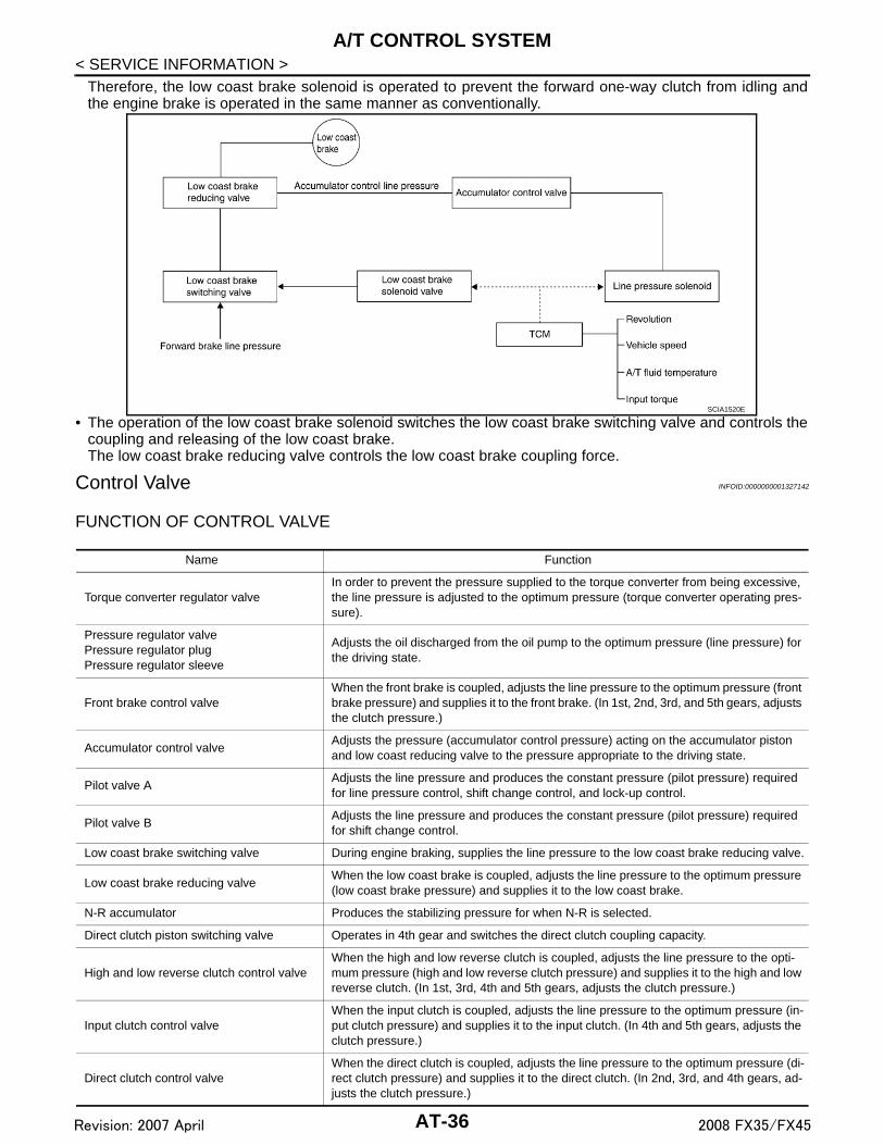
< SERVICE INFORMATION >Therefore, the low coast brake solenoid is operated to prevent the forward one-way clutch from idling andthe engine brake is operated in the same manner as conventionally.
• The operation of the low coast brake solenoid switches the low coast brake switching valve and controls thecoupling and releasing of the low coast brake.The low coast brake reducing valve controls the low coast brake coupling force.
Control Valve INFOID:0000000001327142
FUNCTION OF CONTROL VALVE
SCIA1520E
Name Function
Torque converter regulator valveIn order to prevent the pressure supplied to the torque converter from being excessive, the line pressure is adjusted to the optimum pressure (torque converter operating pres-sure).
Pressure regulator valvePressure regulator plugPressure regulator sleeve
Adjusts the oil discharged from the oil pump to the optimum pressure (line pressure) for the driving state.
Front brake control valveWhen the front brake is coupled, adjusts the line pressure to the optimum pressure (front brake pressure) and supplies it to the front brake. (In 1st, 2nd, 3rd, and 5th gears, adjusts the clutch pressure.)
Accumulator control valveAdjusts the pressure (accumulator control pressure) acting on the accumulator piston and low coast reducing valve to the pressure appropriate to the driving state.
Pilot valve AAdjusts the line pressure and produces the constant pressure (pilot pressure) required for line pressure control, shift change control, and lock-up control.
Pilot valve BAdjusts the line pressure and produces the constant pressure (pilot pressure) required for shift change control.
Low coast brake switching valve During engine braking, supplies the line pressure to the low coast brake reducing valve.
Low coast brake reducing valveWhen the low coast brake is coupled, adjusts the line pressure to the optimum pressure (low coast brake pressure) and supplies it to the low coast brake.
N-R accumulator Produces the stabilizing pressure for when N-R is selected.
Direct clutch piston switching valve Operates in 4th gear and switches the direct clutch coupling capacity.
High and low reverse clutch control valveWhen the high and low reverse clutch is coupled, adjusts the line pressure to the opti-mum pressure (high and low reverse clutch pressure) and supplies it to the high and low reverse clutch. (In 1st, 3rd, 4th and 5th gears, adjusts the clutch pressure.)
Input clutch control valveWhen the input clutch is coupled, adjusts the line pressure to the optimum pressure (in-put clutch pressure) and supplies it to the input clutch. (In 4th and 5th gears, adjusts the clutch pressure.)
Direct clutch control valveWhen the direct clutch is coupled, adjusts the line pressure to the optimum pressure (di-rect clutch pressure) and supplies it to the direct clutch. (In 2nd, 3rd, and 4th gears, ad-justs the clutch pressure.)
AT-36Revision: 2007 April 2008 FX35/FX45
A/T CONTROL SYSTEM
D
E
F
G
H
I
J
K
L
M
A
B
T
N
O
P
< SERVICE INFORMATION >
A
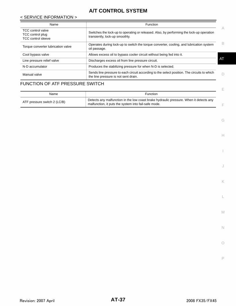
FUNCTION OF ATF PRESSURE SWITCH
TCC control valveTCC control plugTCC control sleeve
Switches the lock-up to operating or released. Also, by performing the lock-up operation transiently, lock-up smoothly.
Torque converter lubrication valveOperates during lock-up to switch the torque converter, cooling, and lubrication system oil passage.
Cool bypass valve Allows excess oil to bypass cooler circuit without being fed into it.
Line pressure relief valve Discharges excess oil from line pressure circuit.
N-D accumulator Produces the stabilizing pressure for when N-D is selected.
Manual valveSends line pressure to each circuit according to the select position. The circuits to which the line pressure is not sent drain.
Name Function
Name Function
ATF pressure switch 2 (LC/B)Detects any malfunction in the low coast brake hydraulic pressure. When it detects any malfunction, it puts the system into fail-safe mode.
AT-37Revision: 2007 April 2008 FX35/FX45

ON BOARD DIAGNOSTIC (OBD) SYSTEM
< SERVICE INFORMATION >ON BOARD DIAGNOSTIC (OBD) SYSTEM
Introduction INFOID:0000000001327143
The A/T system has two self-diagnostic systems.The first is the emission-related on board diagnostic system (OBD-II) performed by the TCM in combinationwith the ECM. The malfunction is indicated by the MIL (malfunction indicator lamp) and is stored as a DTC inthe ECM memory but not the TCM memory.The second is the TCM original self-diagnosis indicated by the A/T CHECK indicator lamp. The malfunction isstored in the TCM memory. The detected items are overlapped with OBD-II self-diagnostic items. For detail,refer to AT-84, "CONSULT-III Function (TRANSMISSION)".
OBD-II Function for A/T System INFOID:0000000001327144
The ECM provides emission-related on board diagnostic (OBD-II) functions for the A/T system. One functionis to receive a signal from the TCM used with OBD-related parts of the A/T system. The signal is sent to theECM when a malfunction occurs in the corresponding OBD-related part. The other function is to indicate adiagnostic result by means of the MIL (malfunction indicator lamp) on the instrument panel. Sensors, switchesand solenoid valves are used as sensing elements.The MIL automatically illuminates in “One or Two Trip Detection Logic” when a malfunction is sensed in rela-tion to A/T system parts.
One or Two Trip Detection Logic of OBD-II INFOID:0000000001327145
ONE TRIP DETECTION LOGICIf a malfunction is sensed during the first test drive, the MIL will illuminate and the malfunction will be stored inthe ECM memory as a DTC. The TCM is not provided with such a memory function.
TWO TRIP DETECTION LOGICWhen a malfunction is sensed during the first test drive, it is stored in the ECM memory as a 1st trip DTC(diagnostic trouble code) or 1st trip freeze frame data. At this point, the MIL will not illuminate. — 1st tripIf the same malfunction as that experienced during the first test drive is sensed during the second test drive,the MIL will illuminate. — 2nd tripThe “Trip” in the “One or Two Trip Detection Logic” means a driving mode in which self-diagnosis is performedduring vehicle operation.
OBD-II Diagnostic Trouble Code (DTC) INFOID:0000000001327146
HOW TO READ DTC AND 1ST TRIP DTCDTC and 1st trip DTC can be read by the following methods.( with CONSULT-III or GST) CONSULT-III or GST (Generic Scan Tool) Examples: P0705, P0720 etc.These DTC are prescribed by SAE J2012.(CONSULT-III also displays the malfunctioning component or system.)• 1st trip DTC No. is the same as DTC No.• Output of the diagnostic trouble code indicates that the indicated circuit has a malfunction. How-
ever, in case of the Mode II and GST, they do not indicate whether the malfunction is still occurring oroccurred in the past and returned to normal.CONSULT-III can identify them as shown below, therefore, CONSULT-III (if available) is recom-mended.
- DTC or 1st trip DTC of malfunction is displayed in SELF-DIAGNOSTIC RESULTS mode for “ENGINE” withCONSULT-III. Time data indicates how many times the vehicle was driven after the last detection of a DTC.
- If the DTC is being detected currently, the time data will be “0”.- If a 1st trip DTC is stored in the ECM, the time data will be “1t”.
Freeze Frame Data and 1st Trip Freeze Frame DataThe ECM has a memory function, which stores the driving condition such as fuel system status, calculatedload value, engine coolant temperature, short term fuel trim, long term fuel trim, engine speed and vehiclespeed at the moment the ECM detects a malfunction.Data which are stored in the ECM memory, along with the 1st trip DTC, are called 1st trip freeze frame data,and the data, stored together with the DTC data, are called freeze frame data and displayed on CONSULT-IIIor GST. The 1st trip freeze frame data can only be displayed on the CONSULT-III screen, not on the GST. For
AT-38Revision: 2007 April 2008 FX35/FX45

ON BOARD DIAGNOSTIC (OBD) SYSTEM
D
E
F
G
H
I
J
K
L
M
A
B
T
N
O
P
< SERVICE INFORMATION >
A
detail, refer to EC-117, "CONSULT-III Function (ENGINE)" (for VQ35DE) or EC-695, "CONSULT-III Function(ENGINE)" (for VK45DE).Only one set of freeze frame data (either 1st trip freeze frame data of freeze frame data) can be stored in theECM. 1st trip freeze frame data is stored in the ECM memory along with the 1st trip DTC. There is no priorityfor 1st trip freeze frame data and it is updated each time a different 1st trip DTC is detected. However, oncefreeze frame data (2nd trip detection/MIL on) is stored in the ECM memory, 1st trip freeze frame data is nolonger stored. Remember, only one set of freeze frame data can be stored in the ECM. The ECM has the fol-lowing priorities to update the data.
Both 1st trip freeze frame data and freeze frame data (along with the DTC) are cleared when the ECM mem-ory is erased.
HOW TO ERASE DTCThe diagnostic trouble code can be erased by CONSULT-III, GST or ECM DIAGNOSTIC TEST MODE asdescribed following.• If the battery cable is disconnected, the diagnostic trouble code will be lost within 24 hours.• When you erase the DTC, using CONSULT-III or GST is easier and quicker than switching the mode
selector on the ECM.The following emission-related diagnostic information is cleared from the ECM memory when erasing DTCrelated to OBD-II. For details, refer to EC-55, "Emission-Related Diagnostic Information" (for VQ35DE) or EC-633, "Emission-related Diagnostic Information" (for VK45DE).• Diagnostic trouble codes (DTC)• 1st trip diagnostic trouble codes (1st trip DTC)• Freeze frame data• 1st trip freeze frame data• System readiness test (SRT) codes• Test values
HOW TO ERASE DTC (WITH CONSULT-III)1. The emission related diagnostic information in the TCM and ECM can be erased by selecting “ALL Erase”
in the “Description” of “FINAL CHECK” mode with CONSULT-III.
HOW TO ERASE DTC (WITH GST)1. If the ignition switch stays ON after repair work, be sure to turn ignition switch OFF once. Wait at least 10
seconds and then turn it ON (engine stopped) again.2. Perform “TCM SELF-DIAGNOSTIC PROCEDURE (No Tools)”. Refer to AT-91, "Diagnosis Procedure
without CONSULT-III". (The engine warm-up step can be skipped when performing the diagnosis only toerase the DTC.)
3. Select Mode 4 with Generic Scan Tool (GST). For details, refer to EC-125, "Generic Scan Tool (GST)Function" (for VQ35DE) or EC-704, "Generic Scan Tool (GST) Function" (for VK45DE).
HOW TO ERASE DTC (NO TOOLS)The A/T CHECK indicator lamp is located on the instrument panel.1. If the ignition switch stays ON after repair work, be sure to turn ignition switch OFF once. Wait at least 10
seconds and then turn it ON (engine stopped) again.2. Perform “TCM SELF-DIAGNOSTIC PROCEDURE (No Tools)”. Refer to AT-91, "Diagnosis Procedure
without CONSULT-III". (The engine warm-up step can be skipped when performing the diagnosis only toerase the DTC.)
3. Perform “OBD-II SELF-DIAGNOSTIC PROCEDURE (No tools)”. Refer to EC-55, "Emission-RelatedDiagnostic Information" (for VQ35DE) or EC-633, "Emission-related Diagnostic Information" (forVK45DE).
Priority Items
1Freeze frame data
Misfire — DTC: P0300 - P0306Fuel Injection System Function — DTC: P0171, P0172, P0174, P0175
2 Except the above items (Includes A/T related items)
3 1st trip freeze frame data
AT-39Revision: 2007 April 2008 FX35/FX45

ON BOARD DIAGNOSTIC (OBD) SYSTEM
< SERVICE INFORMATION >Malfunction Indicator Lamp (MIL) INFOID:0000000001327147
DESCRIPTION The MIL is located on the instrument panel.1. The MIL will light up when the ignition switch is turned ON with-
out the engine running. This is a bulb check.• If the MIL does not light up, refer to DI-34, or see EC-591 (for
VQ35DE) or EC-1194 (for VK45DE).2. When the engine is started, the MIL should go off.
If the MIL remains on, the on board diagnostic system hasdetected an engine system malfunction.
SEF217U
AT-40Revision: 2007 April 2008 FX35/FX45

TROUBLE DIAGNOSIS
D
E
F
G
H
I
J
K
L
M
A
B
T
N
O
P
< SERVICE INFORMATION >
A
TROUBLE DIAGNOSIS
DTC Inspection Priority Chart INFOID:0000000001327148
If some DTCs are displayed at the same time, perform inspections one by one based on the following prioritychart.NOTE:If “DTC U1000” is displayed with other DTCs, first perform the trouble diagnosis for “DTC U1000 CANCOMMUNICATION”. Refer to AT-94.
Fail-Safe INFOID:0000000001327149
The TCM has an electrical fail-safe mode. This mode makes it possible to operate even if there is an error in amain electronic control input/output signal circuit. In fail-safe mode, even if the selector lever is “D” or “M” mode, the transmission is fixed in 2nd, 4th or 5th(depending on the breakdown position), so the customer should feel “slipping” or “poor acceleration”.Even when the electronic circuits are normal, under special conditions (for example, when slamming on thebrake with the wheels spinning drastically and stopping the tire rotation), the transmission can go into fail-safemode. If this happens, switch OFF the ignition switch for 10 seconds, then switch it ON again to return to thenormal shift pattern. Therefore, the customer's vehicle has returned to normal, so handle according to the“WORK FLOW” (Refer to AT-42).
FAIL-SAFE FUNCTION If any malfunction occurs in a sensor or solenoid, this function controls the A/T to mark driving possible.
Vehicle Speed SensorSignals are input from two systems - from vehicle speed sensor A/T (revolution sensor) installed on the trans-mission and from combination meter so normal driving is possible even if there is a malfunction in one of thesystems. And if vehicle speed sensor A/T (revolution sensor) has unusual cases, 5th gear and manual modeare prohibited.
Accelerator Pedal Position SensorIf there is a malfunction in one of the systems, the accelerator opening angle is controlled by ECM accordingto a pre-determined accelerator angle to make driving possible. And if there are malfunctions in tow systems,the engine speed is fixed by ECM to a pre-determined engine speed to make driving possible.
Throttle Position SensorIf there is a malfunction in one of the systems, the accelerator opening angle is controlled by ECM accordingto a pre-determined accelerator angle to make driving possible. And if there are malfunctions in tow systems,the accelerator opening angle is controlled by the idle signal sent from the ECM which is based on input indi-cating either idle condition or off-idle condition (pre-determined accelerator opening) in order to make drivingpossible.
PNP SwitchIn the unlikely event that a malfunction signal enters the TCM, the position indicator is switched OFF, thestarter relay is switched OFF (starter starting is disabled), the back-up lamp relay switched OFF (back-up lampis OFF) and the position is fixed to the “D” position to make driving possible.
Starter RelayThe starter relay is switched OFF. (Starter starting is disabled.)
A/T Interlock• If there is an A/T interlock judgment malfunction, the A/T is fixed in 2nd gear to make driving possible.
NOTE:When the vehicle is driven fixed in 2nd gear, a turbine revolution sensor malfunction is displayed,but this is not a turbine revolution sensor malfunction.
• When the coupling pattern below is detected, the fail-safe action corresponding to the pattern is performed.
A/T 1st Engine Braking
Priority Detected items (DTC)
1 U1000 CAN communication line
2 Except above
AT-41Revision: 2007 April 2008 FX35/FX45

TROUBLE DIAGNOSIS
< SERVICE INFORMATION >When there is an A/T first gear engine brake judgment malfunction, the low coast brake solenoid is switchedOFF to avoid the engine brake operation.Line Pressure SolenoidThe solenoid is switched OFF and the line pressure is set to the maximum hydraulic pressure to make drivingpossible.
Torque Converter Clutch SolenoidThe solenoid is switched OFF to release the lock-up.
Low Coast Brake SolenoidWhen a malfunction (electrical or functional) occurs, in order to make driving possible, if the solenoid is ON,the transmission is held in 2nd gear; if the solenoid is OFF, the A/T is held in 4th gear. (Engine brake is notapplied in 1st and 2nd gear.)
Input Clutch SolenoidIf a malfunction (electrical or functional) occurs with the solenoid either ON or OFF, the A/T is held in 4th gearto make driving possible.
Direct Clutch SolenoidIf a malfunction (electrical or functional) occurs with the solenoid either ON or OFF, the A/T is held in 4th gearto make driving possible.
Front Brake SolenoidIf a malfunction (electrical or functional) occurs with the solenoid ON, in order to make driving possible, the A/T is held in 5th gear; if the solenoid is OFF, 4th gear.
High and Low Reverse Clutch SolenoidIf a malfunction (electrical or functional) occurs with the solenoid either ON or OFF, the A/T is held in 4th gearto make driving possible.
Turbine Revolution Sensor 1 or 2The control is the same as if there were no turbine revolution sensors, 5th gear and manual mode are prohib-ited.
How to Perform Trouble Diagnosis for Quick and Accurate Repair INFOID:0000000001327150
INTRODUCTIONThe TCM receives a signal from the vehicle speed sensor, accelerator pedal position sensor (throttle positionsensor) or PNP switch and provides shift control or lock-up control via A/T solenoid valves.The TCM also communicates with the ECM by means of a signalsent from sensing elements used with the OBD-related parts of theA/T system for malfunction-diagnostic purposes. The TCM is capa-ble of diagnosing malfunctioning parts while the ECM can store mal-functions in its memory.Input and output signals must always be correct and stable in theoperation of the A/T system. The A/T system must be in good oper-ating condition and be free of valve seizure, solenoid valve malfunc-tion, etc.
It is much more difficult to diagnose a error that occurs intermittentlyrather than continuously. Most intermittent errors are caused by poorelectric connections or improper wiring. In this case, careful check-ing of suspected circuits may help prevent the replacement of goodparts.A visual check only may not find the cause of the errors. A road testwith CONSULT-III (or GST) or a circuit tester connected should beperformed. Follow the "WORK FLOW".
SAT631IB
SAT632I
AT-42Revision: 2007 April 2008 FX35/FX45

TROUBLE DIAGNOSIS
D
E
F
G
H
I
J
K
L
M
A
B
T
N
O
P
< SERVICE INFORMATION >
A
Before undertaking actual checks, take a few minutes to talk with acustomer who approaches with a driveability complaint. The cus-tomer can supply good information about such errors, especiallyintermittent ones. Find out what symptoms are present and underwhat conditions they occur. A “DIAGNOSTIC WORKSHEET” asshown on the example (Refer to "Diagnostic Worksheet Chart")should be used.Start your diagnosis by looking for “conventional” errors first. This willhelp troubleshoot driveability errors on an electronically controlledengine vehicle.Also check related Service bulletins.
WORK FLOWA good understanding of the malfunction conditions can make troubleshooting faster and more accurate.In general, each customer feels differently about a malfunction. It is important to fully understand the symp-toms or conditions for a customer complaint.Make good use of the two sheets provided, “Information from Customer” and “Diagnostic worksheet chart”, toperform the best troubleshooting possible.
Work Flow Chart
SEF234G
AT-43Revision: 2007 April 2008 FX35/FX45

TROUBLE DIAGNOSIS
< SERVICE INFORMATION >DIAGNOSTIC WORKSHEET
Information from Customer
KEY POINTS• WHAT..... Vehicle and A/T model• WHEN..... Date, Frequencies• WHERE..... Road conditions• HOW..... Operating conditions, Symptoms
*1. "Information from Customer" *2. "Diagnostic Worksheet Chart" *3. AT-41
*4. AT-49 *5. AT-49, AT-49 *6. AT-49
*7. AT-84 *8. AT-38 *9. AT-41
*10. AT-94 *11. AT-155 *12. AT-167
*13. AT-59 *14. AT-38 *15. AT-94
*16. AT-155 *17.EC-55 (for VQ35DE) or EC-633 (for VK45DE)
SCIA8466E
AT-44Revision: 2007 April 2008 FX35/FX45

TROUBLE DIAGNOSIS
D
E
F
G
H
I
J
K
L
M
A
B
T
N
O
P
< SERVICE INFORMATION >
A
Diagnostic Worksheet Chart
Customer name MR/MS Model and Year VIN
Trans. Model Engine Mileage
Malfunction Date Manuf. Date In Service Date
Frequency Continuous Intermittent ( times a day)
Symptoms Vehicle does not move. ( Any position Particular position)
No up-shift ( 1st → 2nd 2nd → 3rd 3rd → 4th 4th → 5th)
No down-shift ( 5th → 4th 4th → 3rd 3rd → 2nd 2nd → 1st)
Lock-up malfunction
Shift point too high or too low.
Shift shock or slip ( N → D Lock-up Any drive position)
Noise or vibration
No kick down
No pattern select
Others( )
A/T CHECK indicator lamp Continuously lit Not lit
Malfunction indicator lamp (MIL) Continuously lit Not lit
1 Read the item on cautions concerning fail-safe and understand the customer's complaint. AT-41
2
A/T fluid inspection AT-49
Leak (Repair leak location.) State Amount
3
Stall test and line pressure test AT-49
Stall test
Torque converter one-way clutch Front brake High and low reverse clutch Low coast brake Forward brake Reverse brake Forward one-way clutch
1st one-way clutch 3rd one-way clutch Engine Line pressure low Except for input clutch and direct clutch, clutches and brakes OK
Line pressure inspection - Suspected part:
AT-45Revision: 2007 April 2008 FX35/FX45

TROUBLE DIAGNOSIS
< SERVICE INFORMATION >4
Perform all road tests and enter checks in required inspection items. AT-49
4-1.
Check before engine is started AT-53
The A/T CHECK Indicator Lamp does come on. AT-170. Perform self-diagnostics. Enter checks for detected items. AT-84, AT-91.
DTC U1000 CAN COMMUNICATION LINE AT-94. DTC P0615 START SIGNAL CIRCUIT AT-97. DTC P0700 TCM AT-101 DTC P0705 PARK/NEUTRAL POSITION SWITCH AT-102. DTC P0717 TURBINE REVOLUTION SENSOR AT-106. DTC P0720 VEHICLE SPEED SENSOR A/T (REVOLUTION SENSOR) AT-108. DTC P0725 ENGINE SPEED SIGNAL AT-112. DTC P0731 A/T 1ST GEAR FUNCTION AT-114. DTC P0732 A/T 2ND GEAR FUNCTION AT-116. DTC P0733 A/T 3RD GEAR FUNCTION AT-118. DTC P0734 A/T 4TH GEAR FUNCTION AT-120. DTC P0735 A/T 5TH GEAR FUNCTION AT-122. DTC P0740 TORQUE CONVERTER CLUTCH SOLENOID VALVE AT-124. DTC P0744 A/T TCC S/V FUNCTION (LOCK-UP) AT-126. DTC P0745 LINE PRESSURE SOLONOID VALVE AT-128. DTC P1705 THROTTLE POSITION SENSOR AT-130. DTC P1710 A/T FLUID TEMPERATURE SENSOR CIRCUIT AT-132. DTC P1721 VEHICLE SPEED SENSOR MTR AT-137. DTC P1730 A/T INTERLOCK AT-139. DTC P1731 A/T 1ST ENGINE BRAKING AT-141. DTC P1752 INPUT CLUTCH SOLENOID VALVE AT-143. DTC P1757 FRONT BRAKE SOLENOID VALVE AT-145. DTC P1762 DIRECT CLUTCH SOLENOID VALVE AT-147. DTC P1767 HIGH AND LOW REVERSE CLUTCH SOLENOID VALVE AT-149. DTC P1772 LOW COAST BRAKE SOLENOID VALVE AT-151. DTC P1774 LOW COAST BRAKE SOLENOID VALVE FUNCTION AT-153. DTC P1815 MANUAL MODE SWITCH AT-155.
4-2.
Check at Idle AT-53
AT-170, "Engine Cannot Be Started in "P" or "N" Position". AT-171, "In "P" Position, Vehicle Moves When Pushed" AT-172, "In "N" Position, Vehicle Moves". AT-173, "Large Shock ("N" to "D" Position)". AT-175, "Vehicle Does Not Creep Backward in "R" Position". AT-178, "Vehicle Does Not Creep Forward in "D" Position".
4-3.
Cruise Test AT-53
Part 1
AT-180, "Vehicle Cannot Be Started from D1". AT-182, "A/T Does Not Shift: D1→ D2". AT-184, "A/T Does Not Shift: D2→ D3". AT-186, "A/T Does Not Shift: D3→ D4". AT-188, "A/T Does Not Shift: D4→ D5". AT-190, "A/T Does Not Lock-up" AT-192, "A/T Does Not Hold Lock-up Condition". AT-194, "Lock-up Is Not Released". AT-194, "Engine Speed Does Not Return to Idle".
AT-46Revision: 2007 April 2008 FX35/FX45

TROUBLE DIAGNOSIS
D
E
F
G
H
I
J
K
L
M
A
B
T
N
O
P
< SERVICE INFORMATION >
A
4 4-3.
Part 2 AT-53
AT-180, "Vehicle Cannot Be Started from D1". AT-182, "A/T Does Not Shift: D1→ D2". AT-184, "A/T Does Not Shift: D2→ D3". AT-186, "A/T Does Not Shift: D3→ D4".
Part 3 AT-53
AT-195, "Cannot Be Changed to Manual Mode". AT-196, "A/T Does Not Shift: 5th Gear → 4th Gear". AT-197, "A/T Does Not Shift: 4th Gear → 3rd Gear". AT-199, "A/T Does Not Shift: 3rd Gear → 2nd Gear". AT-201, "A/T Does Not Shift: 2nd Gear → 1st Gear". AT-202, "Vehicle Does Not Decelerate by Engine Brake". Perform self-diagnostics. Enter checks for detected items. AT-84, AT-91.
DTC U1000 CAN COMMUNICATION LINE AT-94. DTC P0615 START SIGNAL CIRCUIT AT-97. DTC P0700 TCM AT-101 DTC P0705 PARK/NEUTRAL POSITION SWITCH AT-102. DTC P0717 TURBINE REVOLUTION SENSOR AT-106. DTC P0720 VEHICLE SPEED SENSOR A/T (REVOLUTION SENSOR) AT-108. DTC P0725 ENGINE SPEED SIGNAL AT-112. DTC P0731 A/T 1ST GEAR FUNCTION AT-114. DTC P0732 A/T 2ND GEAR FUNCTION AT-116. DTC P0733 A/T 3RD GEAR FUNCTION AT-118. DTC P0734 A/T 4TH GEAR FUNCTION AT-120. DTC P0735 A/T 5TH GEAR FUNCTION AT-122. DTC P0740 TORQUE CONVERTER CLUTCH SOLENOID VALVE AT-124. DTC P0744 A/T TCC S/V FUNCTION (LOCK-UP) AT-126. DTC P0745 LINE PRESSURE SOLONOID VALVE AT-128. DTC P1705 THROTTLE POSITION SENSOR AT-130. DTC P1710 A/T FLUID TEMPERATURE SENSOR CIRCUIT AT-132. DTC P1721 VEHICLE SPEED SENSOR MTR AT-137. DTC P1730 A/T INTERLOCK AT-139. DTC P1731 A/T 1ST ENGINE BRAKING AT-141. DTC P1752 INPUT CLUTCH SOLENOID VALVE AT-143. DTC P1757 FRONT BRAKE SOLENOID VALVE AT-145. DTC P1762 DIRECT CLUTCH SOLENOID VALVE AT-147. DTC P1767 HIGH AND LOW REVERSE CLUTCH SOLENOID VALVE AT-149. DTC P1772 LOW COAST BRAKE SOLENOID VALVE AT-151. DTC P1774 LOW COAST BRAKE SOLENOID VALVE FUNCTION AT-153. DTC P1815 MANUAL MODE SWITCH AT-155.
5 Inspect each system for items found to be NG in the self-diagnostics and repair or replace the malfunctioning parts.
6 Perform all road tests and enter the checks again for the required items. AT-49
7 For any remaining NG items, perform the “diagnostics procedure” and repair or replace the malfunctioning parts. See the chart for diagnostics by symptoms. (This chart also contains other symptoms and inspection pro-cedures.)
AT-59
8 Erase the results of the self-diagnostics from the TCM and the ECM.AT-84, AT-91
AT-47Revision: 2007 April 2008 FX35/FX45

TROUBLE DIAGNOSIS
< SERVICE INFORMATION >A/T Electrical Parts Location INFOID:0000000001327151
JPDIA0419GB
AT-48Revision: 2007 April 2008 FX35/FX45

TROUBLE DIAGNOSIS
D
E
F
G
H
I
J
K
L
M
A
B
T
N
O
P
< SERVICE INFORMATION >
A
Circuit Diagram INFOID:0000000001327152
Inspections Before Trouble Diagnosis INFOID:0000000001327153
A/T FLUID CHECK
A/T Fluid Leakage and A/T Fluid Level Check Check for A/T fluid leakage and check the A/T fluid level. Refer to AT-11, "Checking A/T Fluid".
TCWM0495E
AT-49Revision: 2007 April 2008 FX35/FX45

TROUBLE DIAGNOSIS
< SERVICE INFORMATION >A/T Fluid Condition CheckInspect the A/T fluid condition.STALL TEST
Stall Test Procedure
1. Inspect the amount of engine oil. Replenish the engine oil if necessary.2. Drive for about 10 minutes to warm up the vehicle so that the A/
T fluid temperature is 50 to 80°C (122 to 176°F). Check theamount of ATF. Replenish if necessary.
3. Securely engage the parking brake so that the tires do not turn.4. Start engine, apply foot brake, and place selector lever in “D”
position.
5. While holding down the foot brake, gradually press down theaccelerator pedal.
6. Quickly read off the stall speed, then quickly remove your footfrom the accelerator pedal.CAUTION:Do not hold down the accelerator pedal for more than 5 sec-onds during this test.
7. Move the selector lever to the “N” position.8. Cool down the ATF.
CAUTION:Run the engine at idle for at least 1 minute.
Fluid condition Conceivable Cause Required Operation
Varnished (viscous varnish state)
Clutch, brake scorched
Replace the ATF and check the A/T main unit and the vehicle for mal-functions (wire harnesses, cooler pipes, etc.)
Milky white or cloudy
Water in the fluidReplace the ATF and check for plac-es where water is getting in.
Large amount of metal powder mixed in
Unusual wear of sliding parts within A/T
Replace the ATF and check for im-proper operation of the A/T. SAT638A
SAT647B
SCIA7463E
Stall speedVQ35DE engine: 2,650 - 2,950 rpmVK45DE engine: 2,260 - 2,560 rpm
SAT514G
AT-50Revision: 2007 April 2008 FX35/FX45

TROUBLE DIAGNOSIS
D
E
F
G
H
I
J
K
L
M
A
B
T
N
O
P
< SERVICE INFORMATION >
A
9. Repeat steps 5 through 8 with selector lever in “R” position.
Judgement of Stall Test
O: Stall speed within standard value position
H: Stall speed higher than standard value
L: Stall speed lower than standard value
Stall test standard value position
LINE PRESSURE TEST
Line Pressure Test Port
Line Pressure Test Procedure
1. Inspect the amount of engine oil and replenish if necessary.2. Drive the car for about 10 minutes to warm it up so that the ATF reaches in range of 50 to 80°C (122 to
176°F), then inspect the amount of ATF and replenish if necessary.NOTE:The A/T fluid temperature rises in range of 50 to 80°C (122 to 176°F) during 10 minutes of driving.
3. Remove the front propeller shaft from vehicle (with AWD models). Refer to PR-4, "Removal and Installa-tion".
4. After warming up remove the oil pressure detection plug andinstall the oil pressure gauge [ST2505S001(J-34301-C)].CAUTION:When using the oil pressure gauge, be sure to use the O-ring attached to the oil pressure detection plug.
Selector lever positionExpected problem location
“D”, “M” “R”
Stall speed
H O
• Forward brake• Forward one-way clutch• 1st one-way clutch• 3rd one-way clutch
O H • Reverse brake
L L • Engine and torque converter one-way clutch
H H • Line pressure low
Does not shift-up “D” or “M” position 1 → 2 Slipping in 2nd, 3rd or 4th gear Direct clutch slippage
Does not shift-up “D” or “M” position 2 → 3 Slipping in 3rd, 4th or 5th gear High and low reverse clutch slippage
Does not shift-up “D” or “M” position 3 → 4 Slipping in 4th or 5th gear Input clutch slippage
Does not shift-up “D” or “M” position 4 → 5 Slipping in 5th gear Front brake slippage
SCIA2187E
SCIA5309E
AT-51Revision: 2007 April 2008 FX35/FX45

TROUBLE DIAGNOSIS
< SERVICE INFORMATION >5. Securely engage the parking brake so that the tires do not turn.6. Start the engine, then measure the line pressure at both idle andthe stall speed.CAUTION:• Keep the brake pedal pressed all the way down during
measurement.• When measuring the line pressure at the stall speed, refer
to "STALL TEST". 7. After the measurements are complete, install the oil pressure
detection plug and tighten to the specified torque.
CAUTION:• Do not reuse the O-ring.• Apply ATF to the O-ring.
Line Pressure
Judgement of Line Pressure Test
SCIA7463E
: 7.3 N·m (0.74 kg-m, 65 in-lb) SAT493G
Engine speedLine pressure kPa (kg/cm2, psi)
“R” position “D” and “M” positions
At idle speed 425 - 465 (4.3 - 4.7, 62 - 67) 379 - 428 (3.9 - 4.4, 55 - 62)
At stall speed 1,605 - 1,950 (16.4 - 19.9, 233 - 283) 1,310 - 1,500 (13.4 - 15.3, 190 - 218)
Judgement Possible cause
Idle speed
Low for all positions (“P”, “R”, “N”, “D”, “M”)
Possible causes include malfunctions in the pressure supply system and low oil pump output.For example• Oil pump wear• Pressure regulator valve or plug sticking or spring fatigue• Oil strainer ⇒ oil pump ⇒ pressure regulator valve passage oil leak• Engine idle speed too low
Only low for a spe-cific position
Possible causes include an oil pressure leak in a passage or device related to the position after the pressure is distributed by the manual valve.
High
Possible causes include a sensor malfunction or malfunction in the line pressure adjustment func-tion.For example• Accelerator pedal position signal malfunction• ATF temperature sensor malfunction• Line pressure solenoid malfunction (sticking in OFF state, filter clog, cut line)• Pressure regulator valve or plug sticking
AT-52Revision: 2007 April 2008 FX35/FX45

TROUBLE DIAGNOSIS
D
E
F
G
H
I
J
K
L
M
A
B
T
N
O
P
< SERVICE INFORMATION >
A
Road Test INFOID:0000000001425855
DESCRIPTION• The road test checks overall performance of the A/T and analyzes possible malfunction causes.• The road test is carried out in the following three stages.1. Check before engine is started.2. Check at idle.3. Cruise test
• Inspect all the items Part 1 to Part 3.• Before beginning the road test, check the procedure and inspection items.• Test all inspection items until the symptom is uncovered. Diagnose NG items when all road tests are com-
plete.
CHECK BEFORE ENGINE IS STARTED
1.CHECK A/T CHECK INDICATOR LAMP
1. Park vehicle on level surface.2. Move selector lever to “P” position.3. Turn ignition switch OFF and wait at least 10 seconds.4. Turn ignition switch ON.Does A/T CHECK indicator lamp light up for about 2 seconds?YES - 1>> With CONSULT-III
1. Perform self-diagnostics and record all NG items on the “Diagnostic Worksheet Chart”. 2. Go to “CHECK AT IDLE”.
YES - 2>> Without CONSULT-III1. Perform self-diagnostics and record all NG items on the “Diagnostic Worksheet Chart”. Refer
to AT-91, "Diagnosis Procedure without CONSULT-III".2. Go to “CHECK AT IDLE”.
NO >> Stop the road test and go to AT-170, "A/T Check Indicator Lamp Does Not Come On".
CHECK AT IDLE
1.CHECK STARTING THE ENGINE
1. Park vehicle on level surface.2. Move selector lever to “P” or “N” position.3. Turn ignition switch OFF.4. Start engine.Does the engine start?YES >> GO TO 2.NO >> Stop the road test and go to AT-170, "Engine Cannot Be Started in "P" or "N" Position".
Stall speed
Line pressure does not rise higher than the line pressure for idle.
Possible causes include a sensor malfunction or malfunction in the pressure adjustment function.For example• Accelerator pedal position signal malfunction• TCM breakdown• Line pressure solenoid malfunction (shorting, sticking in ON state)• Pressure regulator valve or plug sticking• Pilot valve sticking or pilot filter clogged
The pressure rises, but does not enter the standard posi-tion.
Possible causes include malfunctions in the pressure supply system and malfunction in the pres-sure adjustment function.For example• Accelerator pedal position signal malfunction• Line pressure solenoid malfunction (sticking, filter clog)• Pressure regulator valve or plug sticking• Pilot valve sticking or pilot filter clogged
Only low for a spe-cific position
Possible causes include an oil pressure leak in a passage or device related to the position after the pressure is distributed by the manual valve.
Judgement Possible cause
AT-53Revision: 2007 April 2008 FX35/FX45

TROUBLE DIAGNOSIS
< SERVICE INFORMATION >2.CHECK STARTING THE ENGINE
1. Turn ignition switch ON. (Do not start engine.)2. Move selector lever to “D”, “M” or “R” position.3. Start engine.Does the engine start in either position?YES >> Stop the road test and go to AT-170, "Engine Cannot Be Started in "P" or "N" Position".NO >> GO TO 3.
3.CHECK “P” POSITION FUNCTIONS
1. Move selector lever to “P” position.2. Turn ignition switch OFF.3. Disengage the parking brake.4. Push the vehicle forward or backward.5. Engage the parking brake.When you push the vehicle with disengaging the parking brake, does it move?YES >> Enter a check mark at AT-171, "In "P" Position, Vehicle Moves When Pushed" on the “Diagnostic
Worksheet Chart”, then continue the road test.NO >> GO TO 4.
4.CHECK “N” POSITION FUNCTIONS
1. Start engine.2. Move selector lever to “N” position.3. Disengage the parking brake.Does vehicle move forward or backward?YES >> Enter a check mark at AT-172, "In "N" Position, Vehicle Moves" on the “Diagnostic Worksheet
Chart”, then continue the road test. NO >> GO TO 5.
5.CHECK SHIFT SHOCK
1. Engage the brake.2. Move selector lever to “D” position.When the transmission is shifted from “N” to “D”, is there an excessive shock?YES >> Enter a check mark at AT-173, "Large Shock ("N" to "D" Position)"on the “Diagnostic Worksheet
Chart”, then continue the road test.NO >> GO TO 6.
6.CHECK “R” POSITION FUNCTIONS
1. Engage the brake.2. Move selector lever to “R” position.3. Disengage the brake for 4 to 5 seconds.Does the vehicle creep backward?YES >> GO TO 7.NO >> Enter a check mark at AT-175, "Vehicle Does Not Creep Backward in "R" Position" on the “Diag-
nostic Worksheet Chart”, then continue the road test.
7.CHECK “D” POSITION FUNCTIONS
Inspect whether the vehicle creep forward when the A/T is put into the “D” position.Does the vehicle creep forward in the “D” position?YES >> Go to AT-53, "Road Test".NO >> Enter a check mark at AT-178, "Vehicle Does Not Creep Forward in "D" Position"on the “Diagnos-
tic Worksheet Chart”, then continue the road test.
CRUISE TEST - PART 1
1.CHECK STARTING OUT FROM D1
1. Drive the vehicle for about 10 minutes to warm up the engine oil and ATF.Appropriate temperature for the ATF: 50 to 80°C (122 to 176°F)
AT-54Revision: 2007 April 2008 FX35/FX45

TROUBLE DIAGNOSIS
D
E
F
G
H
I
J
K
L
M
A
B
T
N
O
P
< SERVICE INFORMATION >
A
2. Park the vehicle on a level surface.3. Move selector lever to “P” position.4. Start the engine.5. Move selector lever to “D” position.6. Press the accelerator pedal about half-way down to accelerate the vehicle.
With CONSULT-IIIRead the gear positions. Refer to AT-84, "CONSULT-III Function (TRANSMISSION)".Starts from D1?YES >> GO TO 2.NO >> Enter a check mark at AT-180, "Vehicle Cannot Be Started from D1" on the “Diagnostic Worksheet
Chart”, then continue the road test.
2.CHECK SHIFT-UP D1 → D2
Press down the accelerator pedal about half-way and inspect if the vehicle shifts up (D1 → D2) at the appropri-ate speed. Refer to AT-58, "Vehicle Speed at Which Gear Shifting Occurs".
With CONSULT-IIIRead the gear position, throttle degree of opening, and vehicle speed. Refer to AT-84, "CONSULT-III Function(TRANSMISSION)".Does the A/T shift-up D1 → D2 at the correct speed?YES >> GO TO 3.NO >> Enter a check mark at AT-182, "A/T Does Not Shift: D1→ D2" on the “Diagnostic Worksheet
Chart”, then continue the road test.
3.CHECK SHIFT-UP D2 → D3
Press down the accelerator pedal about half-way and inspect if the vehicle shifts up (D2 → D3) at the appropri-ate speed. Refer to AT-58, "Vehicle Speed at Which Gear Shifting Occurs".
With CONSULT-IIIRead the gear position, throttle degree of opening, and vehicle speed. Refer to AT-84, "CONSULT-III Function(TRANSMISSION)".Does the A/T shift-up D2 → D3 at the correct speed?YES >> GO TO 4.NO >> Enter a check mark at AT-184, "A/T Does Not Shift: D2→ D3" on the “Diagnostic Worksheet
Chart”, then continue the road test.
4.CHECK SHIFT-UP D3 → D4
Press down the accelerator pedal about half-way and inspect if the vehicle shifts up (D3 → D4) at the appropri-ate speed. Refer to AT-58, "Vehicle Speed at Which Gear Shifting Occurs".
With CONSULT-IIIRead the gear position, throttle degree of opening, and vehicle speed. Refer to AT-84, "CONSULT-III Function(TRANSMISSION)".Does the A/T shift-up D3 → D4 at the correct speed?YES >> GO TO 5.NO >> Enter a check mark at AT-186, "A/T Does Not Shift: D3→ D4" on the “Diagnostic Worksheet
Chart”, then continue the road test.
5.CHECK SHIFT-UP D4 → D5
Press down the accelerator pedal about half-way and inspect if the vehicle shifts up (D4 → D5) at the appropri-ate speed. Refer to AT-58, "Vehicle Speed at Which Gear Shifting Occurs".
With CONSULT-IIIRead the gear position, throttle degree of opening, and vehicle speed. Refer to AT-84, "CONSULT-III Function(TRANSMISSION)".Does the A/T shift-up D4 → D5 at the correct speed?YES >> GO TO 6.NO >> Enter a check mark at AT-188, "A/T Does Not Shift: D4→ D5" on the “Diagnostic Worksheet
Chart”, then continue the road test.
6.CHECK LOCK-UP
AT-55Revision: 2007 April 2008 FX35/FX45
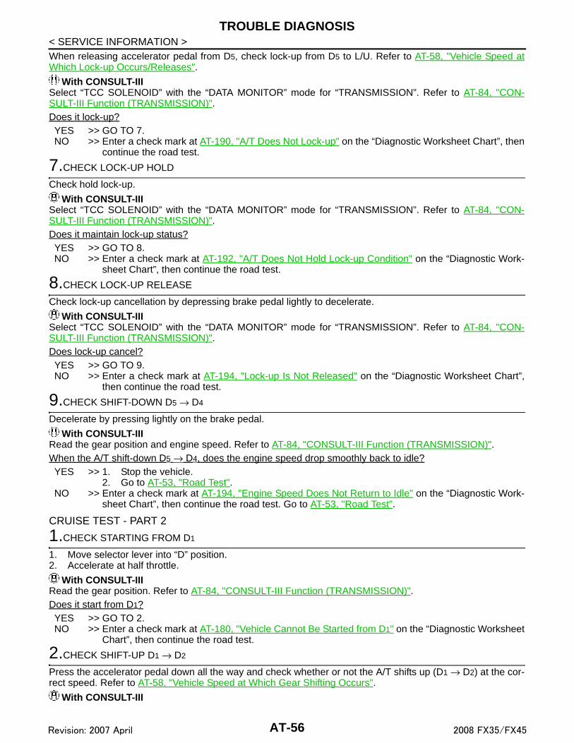
TROUBLE DIAGNOSIS
< SERVICE INFORMATION >When releasing accelerator pedal from D5, check lock-up from D5 to L/U. Refer to AT-58, "Vehicle Speed atWhich Lock-up Occurs/Releases".With CONSULT-IIISelect “TCC SOLENOID” with the “DATA MONITOR” mode for “TRANSMISSION”. Refer to AT-84, "CON-SULT-III Function (TRANSMISSION)".Does it lock-up?YES >> GO TO 7.NO >> Enter a check mark at AT-190, "A/T Does Not Lock-up" on the “Diagnostic Worksheet Chart”, then
continue the road test.
7.CHECK LOCK-UP HOLD
Check hold lock-up.
With CONSULT-IIISelect “TCC SOLENOID” with the “DATA MONITOR” mode for “TRANSMISSION”. Refer to AT-84, "CON-SULT-III Function (TRANSMISSION)".Does it maintain lock-up status?YES >> GO TO 8.NO >> Enter a check mark at AT-192, "A/T Does Not Hold Lock-up Condition" on the “Diagnostic Work-
sheet Chart”, then continue the road test.
8.CHECK LOCK-UP RELEASE
Check lock-up cancellation by depressing brake pedal lightly to decelerate.
With CONSULT-IIISelect “TCC SOLENOID” with the “DATA MONITOR” mode for “TRANSMISSION”. Refer to AT-84, "CON-SULT-III Function (TRANSMISSION)".Does lock-up cancel?YES >> GO TO 9.NO >> Enter a check mark at AT-194, "Lock-up Is Not Released" on the “Diagnostic Worksheet Chart”,
then continue the road test.
9.CHECK SHIFT-DOWN D5 → D4
Decelerate by pressing lightly on the brake pedal.
With CONSULT-IIIRead the gear position and engine speed. Refer to AT-84, "CONSULT-III Function (TRANSMISSION)".When the A/T shift-down D5 → D4, does the engine speed drop smoothly back to idle?YES >> 1. Stop the vehicle.
2. Go to AT-53, "Road Test".NO >> Enter a check mark at AT-194, "Engine Speed Does Not Return to Idle" on the “Diagnostic Work-
sheet Chart”, then continue the road test. Go to AT-53, "Road Test".
CRUISE TEST - PART 2
1.CHECK STARTING FROM D1
1. Move selector lever into “D” position.2. Accelerate at half throttle.
With CONSULT-IIIRead the gear position. Refer to AT-84, "CONSULT-III Function (TRANSMISSION)".Does it start from D1?YES >> GO TO 2.NO >> Enter a check mark at AT-180, "Vehicle Cannot Be Started from D1" on the “Diagnostic Worksheet
Chart”, then continue the road test.
2.CHECK SHIFT-UP D1 → D2
Press the accelerator pedal down all the way and check whether or not the A/T shifts up (D1 → D2) at the cor-rect speed. Refer to AT-58, "Vehicle Speed at Which Gear Shifting Occurs".
With CONSULT-III
AT-56Revision: 2007 April 2008 FX35/FX45

TROUBLE DIAGNOSIS
D
E
F
G
H
I
J
K
L
M
A
B
T
N
O
P
< SERVICE INFORMATION >
A
Read the gear position, throttle position and vehicle speed. Refer to AT-84, "CONSULT-III Function (TRANS-MISSION)".Does the A/T shift-up D1 → D2 at the correct speed?YES >> GO TO 3.NO >> Enter a check mark at AT-182, "A/T Does Not Shift: D1→ D2" on the “Diagnostic Worksheet
Chart”, then continue the road test.
3.CHECK SHIFT-UP D2 → D3
Press the accelerator pedal down all the way and check whether or not the A/T shifts up (D2 → D3) at the cor-rect speed. Refer to AT-58, "Vehicle Speed at Which Gear Shifting Occurs".
With CONSULT-IIIRead the gear position, throttle position and vehicle speed. Refer to AT-84, "CONSULT-III Function (TRANS-MISSION)".Does the A/T shift-up D2 → D3 at the correct speed?YES >> GO TO 4.NO >> Enter a check mark at AT-184, "A/T Does Not Shift: D2→ D3" on the “Diagnostic Worksheet
Chart”, then continue the road test.
4.CHECK SHIFT-UP D3 → D4 AND ENGINE BRAKE
When the A/T changes speed D3 → D4, return the accelerator pedal.
With CONSULT-IIIRead the gear position. Refer to AT-84, "CONSULT-III Function (TRANSMISSION)".Does the A/T shift-up D3 → D4 and apply the engine brake?YES >> 1. Stop the vehicle.
2. Go to AT-53, "Road Test".NO >> Enter a check mark at AT-186, "A/T Does Not Shift: D3→ D4" on the “Diagnostic Worksheet
Chart”, then continue the road test. Go to AT-53, "Road Test".
CRUISE TEST - PART 3
1.MANUAL MODE FUNCTION
Move to manual mode from “D” position.Does it switch to manual mode?YES >> GO TO 2.NO >> Continue road test and add check mark to AT-195, "Cannot Be Changed to Manual Mode" on the
“Diagnostic Worksheet Chart”.
2.CHECK SHIFT-DOWN
During manual mode driving, is downshift from M5 → M4 → M3 → M2 → M1 performed?
With CONSULT-IIIRead the gear position. Refer to AT-84, "CONSULT-III Function (TRANSMISSION)".Is downshifting correctly performed?YES >> GO TO 3.NO >> Enter a check mark at “Vehicle Does Not Shift” at the corresponding position (5th → 4th, 4th →
3rd, 3rd → 2nd, 2nd → 1st) on the “Diagnostic Worksheet Chart”, then continue the road test.
3.CHECK ENGINE BRAKE
Check engine brake.Does engine braking effectively reduce speed in M1 position?YES - 1>> With CONSULT-III
1. Stop the vehicle.2. Perform self-diagnostics.
YES - 2>> Without CONSULT-III1. Stop the vehicle.2. Perform self-diagnostics. Refer to AT-91, "Diagnosis Procedure without CONSULT-III".
NO >> Enter a check mark at AT-202, "Vehicle Does Not Decelerate by Engine Brake" on the “DiagnosticWorksheet Chart”, then continue trouble diagnosis.
AT-57Revision: 2007 April 2008 FX35/FX45

TROUBLE DIAGNOSIS
< SERVICE INFORMATION >Vehicle Speed at Which Gear Shifting Occurs INFOID:0000000001327159
2WD MODELS
• At half throttle, the accelerator opening is 4/8 of the full opening.
AWD MODELS
• At half throttle, the accelerator opening is 4/8 of the full opening.
• At half throttle, the accelerator opening is 4/8 of the full opening.
Vehicle Speed at Which Lock-up Occurs/Releases INFOID:0000000001327160
2WD MODELS
• At closed throttle, the accelerator opening is less than 1/8 condition. (Closed throttle position signal: OFF)
• At half throttle, the accelerator opening is 4/8 of the full opening.
AWD MODELS
Engine model VQ35DE
Throttle positionVehicle speed km/h (MPH)
D1→D2 D2→D3 D3→D4 D4→D5 D5→D4 D4→D3 D3→D2 D2→D1
Full throttle 68 - 72
(42 - 45)106 - 114(66 - 71)
164 - 174(102 - 108)
235 - 245(146 - 152)
231 - 241(144 - 150)
144 - 154(89 - 96)
89 - 97(55 - 60)
43 - 47(27 - 29)
Half throttle 54 - 58
(34 - 36)84 - 90
(52 - 56)127 - 135(79 - 84)
159 - 167(99 - 104)
104 - 112(65 - 70)
75 - 83(47 - 52)
35 - 41(22 - 25)
11 - 15(7 - 9)
Engine model VQ35DE
Throttle positionVehicle speed km/h (MPH)
D1→D2 D2→D3 D3→D4 D4→D5 D5→D4 D4→D3 D3→D2 D2→D1
Full throttle 62 - 66
(39 - 41)96 - 104(60 - 65)
149 - 159(93 - 99)
213 - 223(132 - 139)
209 - 219(130 - 136)
131 - 141(81 - 88)
81 - 89(50 - 55)
39 - 43(24 - 27)
Half throttle 49 - 53
(30 - 33)76 - 82
(47 - 51)115 - 123(71 - 76)
144 - 152(89 - 94)
95 - 103(59 - 64)
67 - 75(42 - 47)
32 - 38(20 - 24)
11 - 15(7 - 9)
Engine model VK45DE
Throttle positionVehicle speed km/h (MPH)
D1→D2 D2→D3 D3→D4 D4→D5 D5→D4 D4→D3 D3→D2 D2→D1
Full throttle 59 - 63
(37 - 39)95 - 103(59 - 64)
147 - 157(92 - 98)
219 - 229(137 - 143)
215 - 225(134 - 141)
130 - 140(81 - 88)
82 - 90(51 - 56)
35 - 39(22 - 24)
Half throttle 48 - 52
(30 - 33)78 - 84
(48 - 52)122 - 130(76 - 81)
154 - 162(96 - 101)
122 - 130(76 - 81)
68 - 76(42 - 47)
40 - 46(25 - 29)
9 - 13(6 - 8)
Engine model VQ35DE
Throttle positionVehicle speed km/h (MPH)
Lock-up ON Lock-up OFF
Closed throttle 65 - 73 (40 - 45) 62 - 70 (39 - 43)
Half throttle 196 - 204 (122 - 127) 153 - 161 (95 - 100)
Engine model VQ35DE
Throttle positionVehicle speed km/h (MPH)
Lock-up ON Lock-up OFF
Closed throttle 59 - 67 (37 - 42) 56 - 64 (35 - 40)
Half throttle 178 - 186 (111 - 116) 139 - 147 (86 - 91)
AT-58Revision: 2007 April 2008 FX35/FX45

TROUBLE DIAGNOSIS
D
E
F
G
H
I
J
K
L
M
A
B
T
N
O
P
< SERVICE INFORMATION >
A
• At closed throttle, the accelerator opening is less than 1/8 condition. (Closed throttle position signal: OFF)
• At half throttle, the accelerator opening is 4/8 of the full opening.
• At closed throttle, the accelerator opening is less than 1/8 condition. (Closed throttle position signal: OFF)
• At half throttle, the accelerator opening is 4/8 of the full opening.
Symptom Chart INFOID:0000000001327161
• The diagnostics item numbers show the sequence for inspection. Check in order from item 1.• Overhaul and check inside the A/T only if A/T fluid condition is NG. Refer to AT-49, "Inspections Before Trou-
ble Diagnosis".
Engine model VK45DE
Throttle positionVehicle speed km/h (MPH)
Lock-up ON Lock-up OFF
Closed throttle 66 - 74 (41 - 46) 53 - 61 (33 - 38)
Half throttle 191 - 199 (119 - 124) 145 - 153 (90 - 95)
No. Items Symptom Condition Diagnostic ItemReference
page
1
Shift Shock
Large shock. (“N” → “D” position)Refer to AT-173, "Large Shock ("N" to "D" Position)".
ON vehicle
1. Engine idle speed
EC-84 (for VQ35DE) or EC-661
(for VK45DE)
2. Engine speed signal AT-112
3. Accelerator pedal position sensor AT-130
4. A/T position AT-207
5. A/T fluid temperature sensor AT-132
6. Front brake solenoid valve AT-145
7. CAN communication line AT-94
8. A/T fluid level and state AT-49
9. Line pressure test AT-49
10. Control valve with TCM AT-215
OFF vehicle
11. Forward brake (Parts behind drum support is impossible to perform inspection by disassembly. Refer to AT-16, "Cross-Sectional View (2WD Models)", AT-17, "Cross-Sectional View (VQ35DE Models for AWD)" or AT-18, "Cross-Sectional View (VK45DE Models for AWD)")
AT-267
2Shock is too large when changing D1 → D2 or M1 → M2.
ON vehicle
1. Accelerator pedal position sensor AT-130
2. A/T position AT-207
3. Direct clutch solenoid valve AT-147
4. CAN communication line AT-94
5. Engine speed signal AT-112
6. Turbine revolution sensor AT-106
7. Vehicle speed sensor A/T and vehicle speed sensor MTRAT-108, AT-137
8. A/T fluid level and state AT-49
9. Control valve with TCM AT-215
OFF vehicle 10. Direct clutch AT-303
AT-59Revision: 2007 April 2008 FX35/FX45

TROUBLE DIAGNOSIS
< SERVICE INFORMATION >3
Shift Shock
Shock is too large when changing D2 → D3 or M2 → M3.
ON vehicle
1. Accelerator pedal position sensor AT-130
2. A/T position AT-207
3.High and low reverse clutch solenoid valve AT-149
4. CAN communication line AT-94
5. Engine speed signal AT-112
6. Turbine revolution sensor AT-106
7. Vehicle speed sensor A/T and vehicle speed sensor MTRAT-108, AT-137
8. A/T fluid level and state AT-49
9. Control valve with TCM AT-215
OFF vehicle 10. High and low reverse clutch AT-301
4Shock is too large when changing D3 → D4 or M3 → M4.
ON vehicle
1. Accelerator pedal position sensor AT-130
2. A/T position AT-207
3. Input clutch solenoid valve AT-143
4. CAN communication line AT-94
5. Engine speed signal AT-112
6. Turbine revolution sensor AT-106
7. Vehicle speed sensor A/T and vehicle speed sensor MTRAT-108, AT-137
8. A/T fluid level and state AT-49
9. Control valve with TCM AT-215
OFF vehicle 10. Input clutch AT-289
5Shock is too large when changing D4 → D5 or M4→ M5.
ON vehicle
1. Accelerator pedal position sensor AT-130
2. A/T position AT-207
3. Front brake solenoid valve AT-145
4. CAN communication line AT-94
5. Engine speed signal AT-112
6. Turbine revolution sensor AT-106
7. Vehicle speed sensor A/T and vehicle speed sensor MTRAT-108, AT-137
8. A/T fluid level and state AT-49
9. Control valve with TCM AT-215
OFF vehicle10. Front brake (brake band) AT-249
11. Input clutch AT-289
No. Items Symptom Condition Diagnostic ItemReference
page
AT-60Revision: 2007 April 2008 FX35/FX45

TROUBLE DIAGNOSIS
D
E
F
G
H
I
J
K
L
M
A
B
T
N
O
P
< SERVICE INFORMATION >
A
6
Shift Shock
Shock is too large for downshift when accel-erator pedal is pressed.
ON vehicle
1. Accelerator pedal position sensor AT-130
2. A/T position AT-207
3. CAN communication line AT-94
4. Engine speed signal AT-112
5. Turbine revolution sensor AT-106
6. Vehicle speed sensor A/T and vehicle speed sensor MTRAT-108, AT-137
7. A/T fluid level and state AT-49
8. Control valve with TCM AT-215
OFF vehicle
9. Front brake (brake band) AT-249
10. Input clutch AT-289
11. High and low reverse clutch AT-301
12. Direct clutch AT-303
7Shock is too large for upshift when accelera-tor pedal is released.
ON vehicle
1. Accelerator pedal position sensor AT-130
2. A/T position AT-207
3. Engine speed signal AT-112
4. CAN communication line AT-94
5. Turbine revolution sensor AT-106
6. Vehicle speed sensor A/T and vehicle speed sensor MTRAT-108, AT-137
7. A/T fluid level and state AT-49
8. Control valve with TCM AT-215
OFF vehicle
9. Front brake (brake band) AT-249
10. Input clutch AT-289
11. High and low reverse clutch AT-301
12. Direct clutch AT-303
8Shock is too large for lock-up.
ON vehicle
1. Accelerator pedal position sensor AT-130
2. A/T position AT-207
3. Engine speed signal AT-112
4. CAN communication line AT-94
5. Turbine revolution sensor AT-106
6. Vehicle speed sensor A/T and vehicle speed sensor MTRAT-108, AT-137
7. Torque converter clutch solenoid valve AT-124
8. A/T fluid level and state AT-49
9. Control valve with TCM AT-215
OFF vehicle 10. Torque converter AT-267
No. Items Symptom Condition Diagnostic ItemReference
page
AT-61Revision: 2007 April 2008 FX35/FX45

TROUBLE DIAGNOSIS
< SERVICE INFORMATION >9Shift Shock
Shock is too large dur-ing engine brake.
ON vehicle
1. Accelerator pedal position sensor AT-130
2. A/T position AT-207
3. CAN communication line AT-94
4. A/T fluid level and state AT-49
5. Control valve with TCM AT-215
OFF vehicle
6. Front brake (brake band) AT-249
7. Input clutch AT-289
8. High and low reverse clutch AT-301
9. Direct clutch AT-303
10
No Up Shift
Gear does not change from D1 to D2 or from M1to M2.Refer to AT-182, "A/T Does Not Shift: D1→ D2".
ON vehicle
1. A/T fluid level and state AT-49
2. Vehicle speed sensor A/T and vehicle speed sensor MTR AT-137
3. Direct clutch solenoid valve AT-147
4. Line pressure test AT-49
5. CAN communication line AT-94
6. Control valve with TCM AT-215
OFF vehicle 7. Direct clutch AT-303
11
Gear does not change from D2 to D3 or from M2 to M3.Refer to AT-184, "A/T Does Not Shift: D2→ D3".
ON vehicle
1. A/T fluid level and state AT-49
2. Vehicle speed sensor A/T and vehicle speed sensor MTRAT-108, AT-137
3. High and low reverse clutch solenoid valve AT-149
4. Line pressure test AT-49
5. CAN communication line AT-94
6. Control valve with TCM AT-215
OFF vehicle 7. High and low reverse clutch AT-301
12
Gear does not change from D3 to D4 or from M3 to M4.Refer to AT-186, "A/T Does Not Shift: D3→ D4".
ON vehicle
1. A/T fluid level and state AT-49
2. Vehicle speed sensor A/T and vehicle speed sensor MTRAT-108, AT-137
3. Input clutch solenoid valve AT-143
4. Front brake solenoid valve AT-145
5. Line pressure test AT-49
6. CAN communication line AT-94
7. Control valve with TCM AT-215
OFF vehicle 8. Input clutch AT-289
13No Up Shift
Gear does not change from D4 to D5 or from M4 to M5.Refer to AT-188, "A/T Does Not Shift: D4→ D5".
ON vehicle
1. A/T fluid level and state AT-49
2. Vehicle speed sensor A/T and vehicle speed sensor MTRAT-108, AT-137
3. Front brake solenoid valve AT-145
4. Direct clutch solenoid valve AT-147
5. Turbine revolution sensor AT-106
6. Line pressure test AT-49
7. CAN communication line AT-94
8. Control valve with TCM AT-215
OFF vehicle9. Front brake (brake band) AT-267
10. Input clutch AT-289
No. Items Symptom Condition Diagnostic ItemReference
page
AT-62Revision: 2007 April 2008 FX35/FX45

TROUBLE DIAGNOSIS
D
E
F
G
H
I
J
K
L
M
A
B
T
N
O
P
< SERVICE INFORMATION >
A14
No Down Shift
In “D” or “M” position, does not downshift to 4th gear.
ON vehicle
1. A/T fluid level and state AT-49
2. Vehicle speed sensor A/T and vehicle speed sensor MTRAT-108, AT-137
3. Front brake solenoid valve AT-145
4. Direct clutch solenoid valve AT-147
5. CAN communication line AT-94
6. Line pressure test AT-49
7. Control valve with TCM AT-215
OFF vehicle8. Front brake (brake band) AT-267
9. Input clutch AT-289
15In “D” or “M” position, does not downshift to 3rd gear.
ON vehicle
1. A/T fluid level and state AT-49
2. Vehicle speed sensor A/T and vehicle speed sensor MTRAT-108, AT-137
3. Input clutch solenoid valve AT-143
4. Front brake solenoid valve AT-145
5. CAN communication line AT-94
6. Line pressure test AT-49
7. Control valve with TCM AT-215
OFF vehicle 8. Input clutch AT-289
16
No Down Shift
In “D” or “M” position, does not downshift to 2nd gear.
ON vehicle
1. A/T fluid level and state AT-49
2. Vehicle speed sensor A/T and vehicle speed sensor MTRAT-108, AT-137
3. High and low reverse clutch solenoid valve AT-149
4. CAN communication line AT-94
5. Line pressure test AT-49
6. Control valve with TCM AT-215
OFF vehicle 7. High and low reverse clutch AT-301
17In “D” or “M” position, does not downshift to 1st gear.
ON vehicle
1. A/T fluid level and state AT-49
2. Vehicle speed sensor A/T and vehicle speed sensor MTRAT-108, AT-137
3. Direct clutch solenoid valve AT-147
4. CAN communication line AT-94
5. Line pressure test AT-49
6. Control valve with TCM AT-215
OFF vehicle 7. Direct clutch AT-303
No. Items Symptom Condition Diagnostic ItemReference
page
AT-63Revision: 2007 April 2008 FX35/FX45

TROUBLE DIAGNOSIS
< SERVICE INFORMATION >18Slips/Will Not En-gage
When “D” or “M” posi-tion, remains in 1st gear.
ON vehicle
1. A/T fluid level and state AT-49
2. Vehicle speed sensor A/T and vehicle speed sensor MTRAT-108, AT-137
3. Direct clutch solenoid valve AT-147
4. Line pressure test AT-49
5. CAN communication line AT-94
6. Control valve with TCM AT-215
OFF vehicle
7. 3rd one-way clutch AT-287
8. 1st one-way clutch AT-295
9. Gear system AT-249
10. Reverse brake AT-267
11. Forward one-way clutch (Parts behind drum support is im-possible to perform inspection by disassembly. Refer to AT-16, "Cross-Sectional View (2WD Models)", AT-17, "Cross-Sectional View (VQ35DE Models for AWD)" or AT-18, "Cross-Sectional View (VK45DE Models for AWD)")
AT-267
12. Forward brake (Parts behind drum support is impossible to perform inspection by disassembly. Refer to AT-16, "Cross-Sectional View (2WD Models)", AT-17, "Cross-Sectional View (VQ35DE Models for AWD)" or AT-18, "Cross-Sectional View (VK45DE Models for AWD)")
AT-267
No. Items Symptom Condition Diagnostic ItemReference
page
AT-64Revision: 2007 April 2008 FX35/FX45
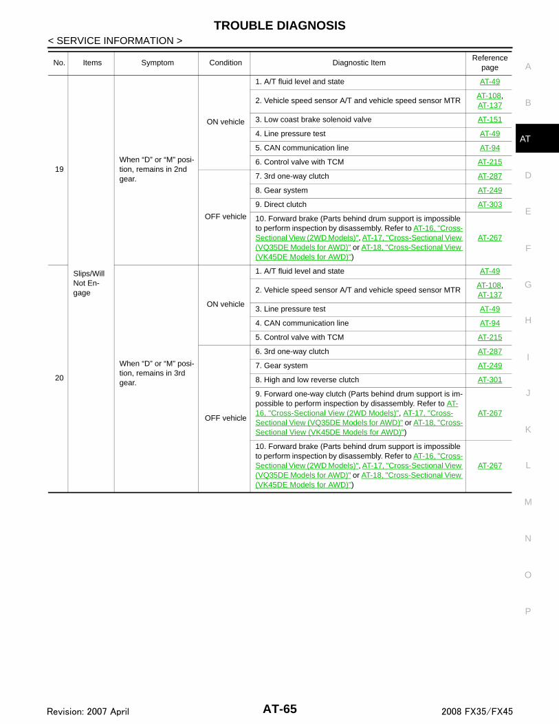
TROUBLE DIAGNOSIS
D
E
F
G
H
I
J
K
L
M
A
B
T
N
O
P
< SERVICE INFORMATION >
A
19
Slips/Will Not En-gage
When “D” or “M” posi-tion, remains in 2nd gear.
ON vehicle
1. A/T fluid level and state AT-49
2. Vehicle speed sensor A/T and vehicle speed sensor MTRAT-108, AT-137
3. Low coast brake solenoid valve AT-151
4. Line pressure test AT-49
5. CAN communication line AT-94
6. Control valve with TCM AT-215
OFF vehicle
7. 3rd one-way clutch AT-287
8. Gear system AT-249
9. Direct clutch AT-303
10. Forward brake (Parts behind drum support is impossible to perform inspection by disassembly. Refer to AT-16, "Cross-Sectional View (2WD Models)", AT-17, "Cross-Sectional View (VQ35DE Models for AWD)" or AT-18, "Cross-Sectional View (VK45DE Models for AWD)")
AT-267
20
When “D” or “M” posi-tion, remains in 3rd gear.
ON vehicle
1. A/T fluid level and state AT-49
2. Vehicle speed sensor A/T and vehicle speed sensor MTRAT-108, AT-137
3. Line pressure test AT-49
4. CAN communication line AT-94
5. Control valve with TCM AT-215
OFF vehicle
6. 3rd one-way clutch AT-287
7. Gear system AT-249
8. High and low reverse clutch AT-301
9. Forward one-way clutch (Parts behind drum support is im-possible to perform inspection by disassembly. Refer to AT-16, "Cross-Sectional View (2WD Models)", AT-17, "Cross-Sectional View (VQ35DE Models for AWD)" or AT-18, "Cross-Sectional View (VK45DE Models for AWD)")
AT-267
10. Forward brake (Parts behind drum support is impossible to perform inspection by disassembly. Refer to AT-16, "Cross-Sectional View (2WD Models)", AT-17, "Cross-Sectional View (VQ35DE Models for AWD)" or AT-18, "Cross-Sectional View (VK45DE Models for AWD)")
AT-267
No. Items Symptom Condition Diagnostic ItemReference
page
AT-65Revision: 2007 April 2008 FX35/FX45

TROUBLE DIAGNOSIS
< SERVICE INFORMATION >21
Slips/Will Not En-gage
When “D” or “M” posi-tion, remains in 4th gear.
ON vehicle
1. A/T fluid level and state AT-49
2. Vehicle speed sensor A/T and vehicle speed sensor MTRAT-108, AT-137
3. Input clutch solenoid valve AT-143
4. Direct clutch solenoid valve AT-147
5. High and low reverse clutch solenoid valve AT-149
6. Low coast brake solenoid valve AT-151
7. Front brake solenoid valve AT-145
8. Line pressure test AT-49
9. CAN communication line AT-94
10. Control valve with TCM AT-215
OFF vehicle
11. Input clutch AT-289
12. Gear system AT-249
13. High and low reverse clutch AT-301
14. Direct clutch AT-303
22When “D” or “M” posi-tion, remains in 5th gear.
ON vehicle
1. A/T fluid level and state AT-49
2. Vehicle speed sensor A/T and vehicle speed sensor MTRAT-108, AT-137
3. Front brake solenoid valve AT-145
4. Line pressure test AT-49
5. CAN communication line AT-94
6. Control valve with TCM AT-215
OFF vehicle
7. Front brake (brake band) AT-267
8. Input clutch AT-289
9. Gear system AT-249
10. High and low reverse clutch AT-301
No. Items Symptom Condition Diagnostic ItemReference
page
AT-66Revision: 2007 April 2008 FX35/FX45

TROUBLE DIAGNOSIS
D
E
F
G
H
I
J
K
L
M
A
B
T
N
O
P
< SERVICE INFORMATION >
A
23
Slips/Will Not En-gage
Vehicle cannot be started from D1.Refer to AT-180, "Ve-hicle Cannot Be Start-ed from D1".
ON vehicle
1. A/T fluid level and state AT-49
2. Accelerator pedal position sensor AT-130
3. Line pressure test AT-49
4. CAN communication line AT-94
5. Control valve with TCM AT-215
OFF vehicle
6. Torque converter AT-267
7. Oil pump assembly AT-285
8. 3rd one-way clutch AT-287
9. 1st one-way clutch AT-295
10. Gear system AT-249
11. Reverse brake AT-267
12. Forward one-way clutch (Parts behind drum support is im-possible to perform inspection by disassembly. Refer to AT-16, "Cross-Sectional View (2WD Models)", AT-17, "Cross-Sectional View (VQ35DE Models for AWD)" or AT-18, "Cross-Sectional View (VK45DE Models for AWD)")
AT-267
13. Forward brake (Parts behind drum support is impossible to perform inspection by disassembly. Refer to AT-16, "Cross-Sectional View (2WD Models)", AT-17, "Cross-Sectional View (VQ35DE Models for AWD)" or AT-18, "Cross-Sectional View (VK45DE Models for AWD)")
AT-267
24Does not lock-up.Refer to AT-190, "A/T Does Not Lock-up".
ON vehicle
1. A/T fluid level and state AT-49
2. Line pressure test AT-49
3. Engine speed signal AT-112
4. Turbine revolution sensor AT-106
5. Torque converter clutch solenoid valve AT-124
6. CAN communication line AT-94
7. Control valve with TCM AT-215
OFF vehicle8. Torque converter AT-267
9. Oil pump assembly AT-285
25
Does not hold lock-up condition.Refer to AT-192, "A/T Does Not Hold Lock-up Condition".
ON vehicle
1. A/T fluid level and state AT-49
2. Line pressure test AT-49
3. Engine speed signal AT-112
4. Turbine revolution sensor AT-106
5. Torque converter clutch solenoid valve AT-124
6. CAN communication line AT-94
7. Control valve with TCM AT-215
OFF vehicle8. Torque converter AT-267
9. Oil pump assembly AT-285
No. Items Symptom Condition Diagnostic ItemReference
page
AT-67Revision: 2007 April 2008 FX35/FX45

TROUBLE DIAGNOSIS
< SERVICE INFORMATION >26
Slips/Will Not En-gage
Lock-up is not re-leased.Refer to AT-194, "Lock-up Is Not Re-leased".
ON vehicle
1. A/T fluid level and state AT-49
2. Line pressure test AT-49
3. Engine speed signal AT-112
4. Turbine revolution sensor AT-106
5. Torque converter clutch solenoid valve AT-124
6. CAN communication line AT-94
7. Control valve with TCM AT-215
OFF vehicle8. Torque converter AT-267
9. Oil pump assembly AT-285
27
No shock at all or the clutch slips when vehi-cle changes speed D1 → D2 or M1 → M2.
ON vehicle
1. A/T fluid level and state AT-49
2. Vehicle speed sensor A/T and vehicle speed sensor MTRAT-108, AT-137
3. Direct clutch solenoid valve AT-147
4. CAN communication line AT-94
5. Line pressure test AT-49
6. Control valve with TCM AT-215
OFF vehicle
7. Torque converter AT-267
8. Oil pump assembly AT-285
9. 3rd one-way clutch AT-287
10. Gear system AT-249
11. Direct clutch AT-303
12. Forward brake (Parts behind drum support is impossible to perform inspection by disassembly. Refer to AT-16, "Cross-Sectional View (2WD Models)", AT-17, "Cross-Sectional View (VQ35DE Models for AWD)" or AT-18, "Cross-Sectional View (VK45DE Models for AWD)")
AT-267
No. Items Symptom Condition Diagnostic ItemReference
page
AT-68Revision: 2007 April 2008 FX35/FX45

TROUBLE DIAGNOSIS
D
E
F
G
H
I
J
K
L
M
A
B
T
N
O
P
< SERVICE INFORMATION >
A
28
Slips/Will Not En-gage
No shock at all or the clutch slips when vehi-cle changes speed D2 → D3 or M2 → M3.
ON vehicle
1. A/T fluid level and state AT-49
2. Vehicle speed sensor A/T and vehicle speed sensor MTRAT-108, AT-137
3. High and low reverse clutch solenoid valve AT-149
4. CAN communication line AT-94
5. Line pressure test AT-49
6. Control valve with TCM AT-215
OFF vehicle
7. Torque converter AT-267
8. Oil pump assembly AT-285
9. 3rd one-way clutch AT-287
10. Gear system AT-249
11. High and low reverse clutch AT-301
12. Forward one-way clutch (Parts behind drum support is im-possible to perform inspection by disassembly. Refer to AT-16, "Cross-Sectional View (2WD Models)", AT-17, "Cross-Sectional View (VQ35DE Models for AWD)" or AT-18, "Cross-Sectional View (VK45DE Models for AWD)")
AT-267
13. Forward brake (Parts behind drum support is impossible to perform inspection by disassembly. Refer to AT-16, "Cross-Sectional View (2WD Models)", AT-17, "Cross-Sectional View (VQ35DE Models for AWD)" or AT-18, "Cross-Sectional View (VK45DE Models for AWD)")
AT-267
29
No shock at all or the clutch slips when vehi-cle changes speed D3 → D4 or M3 → M4.
ON vehicle
1. A/T fluid level and state AT-49
2. Vehicle speed sensor A/T and vehicle speed sensor MTRAT-108, AT-137
3.Input clutch solenoid valve AT-143
4. Front brake solenoid valve AT-145
5. CAN communication line AT-94
6. Line pressure test AT-49
7. Control valve with TCM AT-215
OFF vehicle
8. Torque converter AT-267
9. Oil pump assembly AT-285
10. Input clutch AT-289
11. Gear system AT-249
12. High and low reverse clutch AT-301
13. Direct clutch AT-303
No. Items Symptom Condition Diagnostic ItemReference
page
AT-69Revision: 2007 April 2008 FX35/FX45

TROUBLE DIAGNOSIS
< SERVICE INFORMATION >30
Slips/Will Not En-gage
No shock at all or the clutch slips when vehi-cle changes speed D4 → D5 or M4 → M5.
ON vehicle
1. A/T fluid level and state AT-49
2. Vehicle speed sensor A/T and vehicle speed sensor MTRAT-108, AT-137
3. Front brake solenoid valve AT-145
4. Direct clutch solenoid valve AT-147
5. CAN communication line AT-94
6. Line pressure test AT-49
7. Control valve with TCM AT-215
OFF vehicle
8. Torque converter AT-267
9. Oil pump assembly AT-285
10. Front brake (brake band) AT-267
11. Input clutch AT-289
12. Gear system AT-249
13. High and low reverse clutch AT-301
31
When you press the accelerator pedal and shift speed D5 → D4 or M5 → M4 the engine idles or the A/T slips.
ON vehicle
1. A/T fluid level and state AT-49
2. Vehicle speed sensor A/T and vehicle speed sensor MTRAT-108, AT-137
3. Front brake solenoid valve AT-145
4. Direct clutch solenoid valve AT-147
5. CAN communication line AT-94
6. Line pressure test AT-49
7. Control valve with TCM AT-215
OFF vehicle
8. Torque converter AT-267
9. Oil pump assembly AT-285
10. Input clutch AT-289
11. Gear system AT-249
12. High and low reverse clutch AT-301
13. Direct clutch AT-303
No. Items Symptom Condition Diagnostic ItemReference
page
AT-70Revision: 2007 April 2008 FX35/FX45

TROUBLE DIAGNOSIS
D
E
F
G
H
I
J
K
L
M
A
B
T
N
O
P
< SERVICE INFORMATION >
A
32
Slips/Will Not En-gage
When pressing the ac-celerator pedal and shifting speed D4 → D3 or M4→ M3 the en-gine idles or the A/T slips.
ON vehicle
1. A/T fluid level and state AT-49
2. Vehicle speed sensor A/T and vehicle speed sensor MTRAT-108, AT-137
3. Input clutch solenoid valve AT-143
4. Front brake solenoid valve AT-145
5. CAN communication line AT-94
6. Line pressure test AT-49
7. Control valve with TCM AT-215
OFF vehicle
8. Torque converter AT-267
9. Oil pump assembly AT-285
10. 3rd one-way clutch AT-287
11. Gear system AT-249
12. High and low reverse clutch AT-301
13. Forward one-way clutch (Parts behind drum support is im-possible to perform inspection by disassembly. Refer to AT-16, "Cross-Sectional View (2WD Models)", AT-17, "Cross-Sectional View (VQ35DE Models for AWD)" or AT-18, "Cross-Sectional View (VK45DE Models for AWD)")
AT-267
14. Forward brake (Parts behind drum support is impossible to perform inspection by disassembly. Refer to AT-16, "Cross-Sectional View (2WD Models)", AT-17, "Cross-Sectional View (VQ35DE Models for AWD)" or AT-18, "Cross-Sectional View (VK45DE Models for AWD)")
AT-267
33
When pressing the ac-celerator pedal and shifting speed D3 → D2 or M3→ M2 the en-gine idles or the A/T slips.
ON vehicle
1. A/T fluid level and state AT-49
2. Vehicle speed sensor A/T and vehicle speed sensor MTRAT-108, AT-137
3. High and low reverse clutch solenoid valve AT-149
4.Direct clutch solenoid valve AT-147
5. CAN communication line AT-94
6. Line pressure test AT-49
7. Control valve with TCM AT-215
OFF vehicle
8. Torque converter AT-267
9. Oil pump assembly AT-285
10. 3rd one-way clutch AT-287
11. Gear system AT-249
12. Direct clutch AT-303
13. Forward brake (Parts behind drum support is impossible to perform inspection by disassembly. Refer to AT-16, "Cross-Sectional View (2WD Models)", AT-17, "Cross-Sectional View (VQ35DE Models for AWD)" or AT-18, "Cross-Sectional View (VK45DE Models for AWD)")
AT-267
No. Items Symptom Condition Diagnostic ItemReference
page
AT-71Revision: 2007 April 2008 FX35/FX45
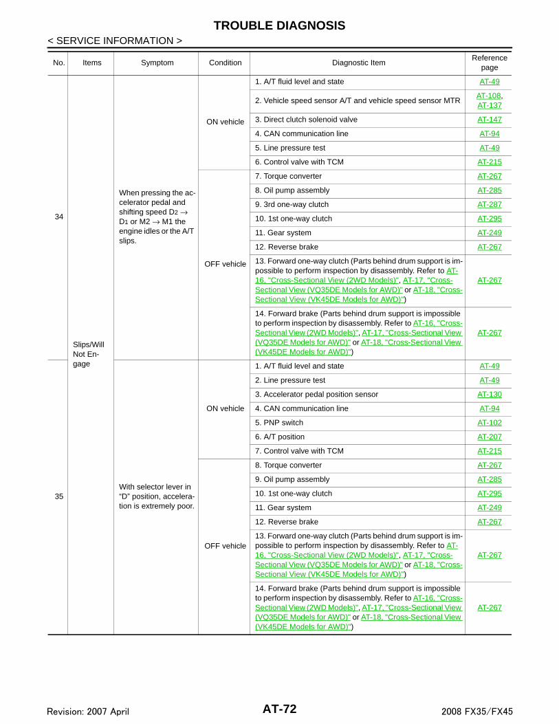
TROUBLE DIAGNOSIS
< SERVICE INFORMATION >34
Slips/Will Not En-gage
When pressing the ac-celerator pedal and shifting speed D2 → D1 or M2 → M1 the engine idles or the A/T slips.
ON vehicle
1. A/T fluid level and state AT-49
2. Vehicle speed sensor A/T and vehicle speed sensor MTRAT-108, AT-137
3. Direct clutch solenoid valve AT-147
4. CAN communication line AT-94
5. Line pressure test AT-49
6. Control valve with TCM AT-215
OFF vehicle
7. Torque converter AT-267
8. Oil pump assembly AT-285
9. 3rd one-way clutch AT-287
10. 1st one-way clutch AT-295
11. Gear system AT-249
12. Reverse brake AT-267
13. Forward one-way clutch (Parts behind drum support is im-possible to perform inspection by disassembly. Refer to AT-16, "Cross-Sectional View (2WD Models)", AT-17, "Cross-Sectional View (VQ35DE Models for AWD)" or AT-18, "Cross-Sectional View (VK45DE Models for AWD)")
AT-267
14. Forward brake (Parts behind drum support is impossible to perform inspection by disassembly. Refer to AT-16, "Cross-Sectional View (2WD Models)", AT-17, "Cross-Sectional View (VQ35DE Models for AWD)" or AT-18, "Cross-Sectional View (VK45DE Models for AWD)")
AT-267
35With selector lever in “D” position, accelera-tion is extremely poor.
ON vehicle
1. A/T fluid level and state AT-49
2. Line pressure test AT-49
3. Accelerator pedal position sensor AT-130
4. CAN communication line AT-94
5. PNP switch AT-102
6. A/T position AT-207
7. Control valve with TCM AT-215
OFF vehicle
8. Torque converter AT-267
9. Oil pump assembly AT-285
10. 1st one-way clutch AT-295
11. Gear system AT-249
12. Reverse brake AT-267
13. Forward one-way clutch (Parts behind drum support is im-possible to perform inspection by disassembly. Refer to AT-16, "Cross-Sectional View (2WD Models)", AT-17, "Cross-Sectional View (VQ35DE Models for AWD)" or AT-18, "Cross-Sectional View (VK45DE Models for AWD)")
AT-267
14. Forward brake (Parts behind drum support is impossible to perform inspection by disassembly. Refer to AT-16, "Cross-Sectional View (2WD Models)", AT-17, "Cross-Sectional View (VQ35DE Models for AWD)" or AT-18, "Cross-Sectional View (VK45DE Models for AWD)")
AT-267
No. Items Symptom Condition Diagnostic ItemReference
page
AT-72Revision: 2007 April 2008 FX35/FX45

TROUBLE DIAGNOSIS
D
E
F
G
H
I
J
K
L
M
A
B
T
N
O
P
< SERVICE INFORMATION >
A36
Slips/Will Not En-gage
With selector lever in “R” position, accelera-tion is extremely poor.
ON vehicle
1. A/T fluid level and state AT-49
2. Line pressure test AT-49
3. Accelerator pedal position sensor AT-130
4. High and low reverse clutch solenoid valve AT-149
5. CAN communication line AT-94
6. PNP switch AT-102
7. A/T position AT-207
8. Control valve with TCM AT-215
OFF vehicle
9. Gear system AT-249
10. Output shaft AT-267
11. Reverse brake AT-267
37
While starting off by accelerating in 1st, en-gine races or slippage occurs.
ON vehicle
1. A/T fluid level and state AT-49
2. Line pressure test AT-49
3. Accelerator pedal position sensor AT-130
4. CAN communication line AT-94
5. Control valve with TCM AT-215
OFF vehicle
6. Torque converter AT-267
7. Oil pump assembly AT-285
8. 3rd one-way clutch AT-287
9. 1st one-way clutch AT-295
10. Gear system AT-249
11. Reverse brake AT-267
12. Forward one-way clutch (Parts behind drum support is im-possible to perform inspection by disassembly. Refer to AT-16, "Cross-Sectional View (2WD Models)", AT-17, "Cross-Sectional View (VQ35DE Models for AWD)" or AT-18, "Cross-Sectional View (VK45DE Models for AWD)")
AT-267
13. Forward brake (Parts behind drum support is impossible to perform inspection by disassembly. Refer to AT-16, "Cross-Sectional View (2WD Models)", AT-17, "Cross-Sectional View (VQ35DE Models for AWD)" or AT-18, "Cross-Sectional View (VK45DE Models for AWD)")
AT-267
No. Items Symptom Condition Diagnostic ItemReference
page
AT-73Revision: 2007 April 2008 FX35/FX45

TROUBLE DIAGNOSIS
< SERVICE INFORMATION >38
Slips/Will Not En-gage
While accelerating in 2nd, engine races or slippage occurs.
ON vehicle
1. A/T fluid level and state AT-49
2. Line pressure test AT-49
3. Accelerator pedal position sensor AT-130
4. CAN communication line AT-94
5. Direct clutch solenoid valve AT-147
6. Control valve with TCM AT-215
OFF vehicle
7. Torque converter AT-267
8. Oil pump assembly AT-285
9. 3rd one-way clutch AT-287
10. Gear system AT-249
11. Direct clutch AT-303
12. Forward brake (Parts behind drum support is impossible to perform inspection by disassembly. Refer to AT-16, "Cross-Sectional View (2WD Models)", AT-17, "Cross-Sectional View (VQ35DE Models for AWD)" or AT-18, "Cross-Sectional View (VK45DE Models for AWD)")
AT-267
39While accelerating in 3rd, engine races or slippage occurs.
ON vehicle
1. A/T fluid level and state AT-49
2. Line pressure test AT-49
3. Accelerator pedal position sensor AT-130
4. CAN communication line AT-94
5. High and low reverse clutch solenoid valve AT-149
6. Control valve with TCM AT-215
OFF vehicle
7. Torque converter AT-267
8. Oil pump assembly AT-285
9. 3rd one-way clutch AT-287
10. Gear system AT-249
11. High and low reverse clutch AT-301
12. Forward one-way clutch (Parts behind drum support is im-possible to perform inspection by disassembly. Refer to AT-16, "Cross-Sectional View (2WD Models)", AT-17, "Cross-Sectional View (VQ35DE Models for AWD)" or AT-18, "Cross-Sectional View (VK45DE Models for AWD)")
AT-267
13. Forward brake (Parts behind drum support is impossible to perform inspection by disassembly. Refer to AT-16, "Cross-Sectional View (2WD Models)", AT-17, "Cross-Sectional View (VQ35DE Models for AWD)" or AT-18, "Cross-Sectional View (VK45DE Models for AWD)")
AT-267
No. Items Symptom Condition Diagnostic ItemReference
page
AT-74Revision: 2007 April 2008 FX35/FX45

TROUBLE DIAGNOSIS
D
E
F
G
H
I
J
K
L
M
A
B
T
N
O
P
< SERVICE INFORMATION >
A
40
Slips/Will Not En-gage
While accelerating in 4th, engine races or slippage occurs.
ON vehicle
1. A/T fluid level and state AT-49
2. Line pressure test AT-49
3. Accelerator pedal position sensor AT-130
4. CAN communication line AT-94
5. Input clutch solenoid valve AT-143
6. Control valve with TCM AT-215
OFF vehicle
7. Torque converter AT-267
8. Oil pump assembly AT-285
9. Input clutch AT-289
10. Gear system AT-249
11. High and low reverse clutch AT-301
12. Direct clutch AT-303
41While accelerating in 5th, engine races or slippage occurs.
ON vehicle
1. A/T fluid level and state AT-49
2. Line pressure test AT-49
3. Accelerator pedal position sensor AT-130
4. CAN communication line AT-94
5. Front brake solenoid valve AT-145
6. Control valve with TCM AT-215
OFF vehicle
7. Torque converter AT-267
8. Oil pump assembly AT-285
9. Front brake (brake band) AT-267
10. Input clutch AT-289
11. Gear system AT-249
12. High and low reverse clutch AT-301
42 Slips at lock-up.
ON vehicle
1. A/T fluid level and state AT-49
2. Line pressure test AT-49
3. Engine speed signal AT-112
4. Turbine revolution sensor AT-106
5. Torque converter clutch solenoid valve AT-124
6. CAN communication line AT-94
7. Control valve with TCM AT-215
OFF vehicle8. Torque converter AT-267
9. Oil pump assembly AT-285
No. Items Symptom Condition Diagnostic ItemReference
page
AT-75Revision: 2007 April 2008 FX35/FX45

TROUBLE DIAGNOSIS
< SERVICE INFORMATION >43
Slips/Will Not En-gage
No creep at all.Refer to AT-175, "Ve-hicle Does Not Creep Backward in "R" Posi-tion", AT-178, "Vehicle Does Not Creep For-ward in "D" Position"
ON vehicle
1. A/T fluid level and state AT-49
2. Line pressure test AT-49
3. Accelerator pedal position sensor AT-130
4. Direct clutch solenoid valve AT-147
5. PNP switch AT-102
6. CAN communication line AT-94
7. A/T position AT-207
8. Control valve with TCM AT-215
OFF vehicle
9. Torque converter AT-267
10. Oil pump assembly AT-285
11. 1st one-way clutch AT-295
12. Gear system AT-249
13. Reverse brake AT-267
14. Direct clutch AT-303
15. Forward one-way clutch (Parts behind drum support is im-possible to perform inspection by disassembly. Refer to AT-16, "Cross-Sectional View (2WD Models)", AT-17, "Cross-Sectional View (VQ35DE Models for AWD)" or AT-18, "Cross-Sectional View (VK45DE Models for AWD)")
AT-267
16. Forward brake (Parts behind drum support is impossible to perform inspection by disassembly. Refer to AT-16, "Cross-Sectional View (2WD Models)", AT-17, "Cross-Sectional View (VQ35DE Models for AWD)" or AT-18, "Cross-Sectional View (VK45DE Models for AWD)")
AT-267
44Vehicle cannot run in all positions.
ON vehicle
1. A/T fluid level and state AT-49
2. Line pressure test AT-49
3. PNP switch AT-102
4. A/T position AT-207
5. Control valve with TCM AT-215
OFF vehicle
6. Oil pump assembly AT-285
7. Gear system AT-249
8. Output shaft AT-267
No. Items Symptom Condition Diagnostic ItemReference
page
AT-76Revision: 2007 April 2008 FX35/FX45

TROUBLE DIAGNOSIS
D
E
F
G
H
I
J
K
L
M
A
B
T
N
O
P
< SERVICE INFORMATION >
A
45
Slips/Will Not En-gage
With selector lever in “D” position, driving is not possible.
ON vehicle
1. A/T fluid level and state AT-49
2. Line pressure test AT-49
3. PNP switch AT-102
4. A/T position AT-207
5. Control valve with TCM AT-215
OFF vehicle
6. Torque converter AT-267
7. Oil pump assembly AT-285
8. 1st one-way clutch AT-295
9. Gear system AT-249
10. Reverse brake AT-267
11. Forward one-way clutch (Parts behind drum support is im-possible to perform inspection by disassembly. Refer to AT-16, "Cross-Sectional View (2WD Models)", AT-17, "Cross-Sectional View (VQ35DE Models for AWD)" or AT-18, "Cross-Sectional View (VK45DE Models for AWD)")
AT-267
12. Forward brake (Parts behind drum support is impossible to perform inspection by disassembly. Refer to AT-16, "Cross-Sectional View (2WD Models)", AT-17, "Cross-Sectional View (VQ35DE Models for AWD)" or AT-18, "Cross-Sectional View (VK45DE Models for AWD)")
AT-267
46With selector lever in “R” position, driving is not possible.
ON vehicle
1. A/T fluid level and state AT-49
2. Line pressure test AT-49
3. PNP switch AT-102
4. A/T position AT-207
5. Control valve with TCM AT-215
OFF vehicle
6. Gear system AT-249
7. Output shaft AT-267
8. Reverse brake AT-267
47Does Not Change
Does not change M5 → M4.Refer to AT-196, "A/T Does Not Shift: 5th Gear → 4th Gear".
ON vehicle
1. PNP switch AT-102
2. A/T fluid level and state AT-49
3. A/T position AT-207
4. Manual mode switch AT-155
5. CAN communication line AT-94
6. Control valve with TCM AT-215
OFF vehicle 7. Front brake (brake band) AT-267
No. Items Symptom Condition Diagnostic ItemReference
page
AT-77Revision: 2007 April 2008 FX35/FX45

TROUBLE DIAGNOSIS
< SERVICE INFORMATION >48
Does Not Change
Does not change M4 → M3.Refer to AT-197, "A/T Does Not Shift: 4th Gear → 3rd Gear".
ON vehicle
1. PNP switch AT-102
2. A/T fluid level and state AT-49
3. A/T position AT-207
4. Manual mode switch AT-155
5. CAN communication line AT-94
6. Control valve with TCM AT-215
OFF vehicle7. Front brake (brake band) AT-267
8. Input clutch AT-289
49
Does not change M3 → M2.Refer to AT-199, "A/T Does Not Shift: 3rd Gear → 2nd Gear".
ON vehicle
1. PNP switch AT-102
2. A/T fluid level and state AT-49
3. A/T position AT-207
4. Manual mode switch AT-155
5. CAN communication line AT-94
6. Control valve with TCM AT-215
OFF vehicle
7. Front brake (brake band) AT-267
8. Input clutch AT-289
9. High and low reverse clutch AT-301
50
Does not change M2 → M1.Refer to AT-201, "A/T Does Not Shift: 2nd Gear → 1st Gear".
ON vehicle
1. PNP switch AT-102
2. A/T fluid level and state AT-49
3. A/T position AT-207
4. Manual mode switch AT-155
5. CAN communication line AT-94
6. Control valve with TCM AT-215
OFF vehicle
7. Input clutch AT-289
8. High and low reverse clutch AT-301
9. Direct clutch AT-303
51
Cannot be changed to manual mode.Refer to AT-195, "Can-not Be Changed to Manual Mode".
ON vehicle
1. Manual mode switch AT-155
2. Turbine revolution sensor AT-106
3. CAN communication line AT-94
52 OthersShift point is high in “D” position.
ON vehicle
1. Vehicle speed sensor A/T and vehicle speed sensor MTRAT-108, AT-137
2. Accelerator pedal position sensor AT-130
3. CAN communication line AT-94
4. ATF temperature sensor AT-132
5. Control valve with TCM AT-215
No. Items Symptom Condition Diagnostic ItemReference
page
AT-78Revision: 2007 April 2008 FX35/FX45

TROUBLE DIAGNOSIS
D
E
F
G
H
I
J
K
L
M
A
B
T
N
O
P
< SERVICE INFORMATION >
A
53
Others
Shift point is low in “D” position.
ON vehicle
1. Vehicle speed sensor A/T and vehicle speed sensor MTRAT-108, AT-137
2. Accelerator pedal position sensor AT-130
3. CAN communication line AT-94
4. Control valve with TCM AT-215
54Judder occurs during lock-up.
ON vehicle
1. A/T fluid level and state AT-49
2. Engine speed signal AT-112
3. Turbine revolution sensor AT-106
4. Vehicle speed sensor A/T and vehicle speed sensor MTRAT-108, AT-137
5. Accelerator pedal position sensor AT-130
6. CAN communication line AT-94
7. Torque converter clutch solenoid valve AT-124
8. Control valve with TCM AT-215
OFF vehicle 9. Torque converter AT-267
55Strange noise in “R” position.
ON vehicle
1. A/T fluid level and state AT-49
2. Engine speed signal AT-112
3. CAN communication line AT-94
4. Control valve with TCM AT-215
OFF vehicle
5. Torque converter AT-267
6. Oil pump assembly AT-285
7. Gear system AT-249
8. High and low reverse clutch AT-301
9. Reverse brake AT-267
56Strange noise in “N” position.
ON vehicle
1. A/T fluid level and state AT-49
2. Engine speed signal AT-112
3. CAN communication line AT-94
4. Control valve with TCM AT-215
OFF vehicle
5. Torque converter AT-267
6. Oil pump assembly AT-285
7. Gear system AT-249
No. Items Symptom Condition Diagnostic ItemReference
page
AT-79Revision: 2007 April 2008 FX35/FX45

TROUBLE DIAGNOSIS
< SERVICE INFORMATION >57
Others
Strange noise in “D” position.
ON vehicle
1. A/T fluid level and state AT-49
2. Engine speed signal AT-112
3. CAN communication line AT-94
4. Control valve with TCM AT-215
OFF vehicle
5. Torque converter AT-267
6. Oil pump assembly AT-285
7. Gear system AT-249
8. Forward brake (Parts behind drum support is impossible to perform inspection by disassembly. Refer to AT-16, "Cross-Sectional View (2WD Models)", AT-17, "Cross-Sectional View (VQ35DE Models for AWD)" or AT-18, "Cross-Sectional View (VK45DE Models for AWD)")
AT-267
58
Vehicle does not de-celerate by engine brake.Refer to AT-202, "Ve-hicle Does Not Decel-erate by Engine Brake".
ON vehicle
1. PNP switch AT-102
2. A/T fluid level and state AT-49
3. A/T position AT-207
4. Manual mode switch AT-155
5. CAN communication line AT-94
6. Control valve with TCM AT-215
OFF vehicle
7. Input clutch AT-289
8. High and low reverse clutch AT-301
9. Direct clutch AT-303
59Engine brake does not work M5 → M4.
ON vehicle
1. PNP switch AT-102
2. A/T fluid level and state AT-49
3. A/T position AT-207
4. Manual mode switch AT-155
5. CAN communication line AT-94
6. Control valve with TCM AT-215
OFF vehicle 7. Front brake (brake band) AT-267
60Engine brake does not work M4 → M3.
ON vehicle
1. PNP switch AT-102
2. A/T fluid level and state AT-49
3. A/T position AT-207
4. Manual mode switch AT-155
5. CAN communication line AT-94
6. Control valve with TCM AT-215
OFF vehicle7. Front brake (brake band) AT-267
8. Input clutch AT-289
No. Items Symptom Condition Diagnostic ItemReference
page
AT-80Revision: 2007 April 2008 FX35/FX45

TROUBLE DIAGNOSIS
D
E
F
G
H
I
J
K
L
M
A
B
T
N
O
P
< SERVICE INFORMATION >
A61
Others
Engine brake does not work M3 → M2.
ON vehicle
1. PNP switch AT-102
2. A/T fluid level and state AT-49
3. A/T position AT-207
4. Manual mode switch AT-155
5. CAN communication line AT-94
6. Control valve with TCM AT-215
OFF vehicle
7. Front brake (brake band) AT-267
8. Input clutch AT-289
9. High and low reverse clutch AT-301
62Engine brake does not work M2 → M1.
ON vehicle
1. PNP switch AT-102
2. A/T fluid level and state AT-49
3. A/T position AT-207
4. Manual mode switch AT-155
5. CAN communication line AT-94
6. Control valve with TCM AT-215
OFF vehicle
7. Input clutch AT-289
8. High and low reverse clutch AT-301
9. Direct clutch AT-303
63 Maximum speed low.
ON vehicle
1. A/T fluid level and state AT-49
2. Line pressure test AT-49
3. Accelerator pedal position sensor AT-130
4. CAN communication line AT-94
5. Direct clutch solenoid valve AT-147
6. Control valve with TCM AT-215
OFF vehicle
7. Torque converter AT-267
8. Oil pump assembly AT-285
9. Input clutch AT-289
10. Gear system AT-249
11. High and low reverse clutch AT-301
12. Direct clutch AT-303
13. Forward one-way clutch (Parts behind drum support is im-possible to perform inspection by disassembly. Refer to AT-16, "Cross-Sectional View (2WD Models)", AT-17, "Cross-Sectional View (VQ35DE Models for AWD)" or AT-18, "Cross-Sectional View (VK45DE Models for AWD)")
AT-267
14. Forward brake (Parts behind drum support is impossible to perform inspection by disassembly. Refer to AT-16, "Cross-Sectional View (2WD Models)", AT-17, "Cross-Sectional View (VQ35DE Models for AWD)" or AT-18, "Cross-Sectional View (VK45DE Models for AWD)")
AT-267
No. Items Symptom Condition Diagnostic ItemReference
page
AT-81Revision: 2007 April 2008 FX35/FX45

TROUBLE DIAGNOSIS
< SERVICE INFORMATION >64
Others
Extremely large creep.ON vehicle
1. Engine idle speed
EC-84 (for VQ35DE) or EC-661
(for VK45DE)
2. CAN communication line AT-94
OFF vehicle 3. Torque converter AT-267
65
With selector lever in “P” position, vehicle does not enter parking condition or, with se-lector lever in another position, parking con-dition is not cancelled.Refer to AT-171, "In "P" Position, Vehicle Moves When Pushed".
ON vehicle1. PNP switch AT-102
2. A/T position AT-207
OFF vehicle 3. Parking pawl components
AT-226(2WD models) or
AT-267 (AWD
models)
66Vehicle runs with A/T in “P” position.
ON vehicle
1. PNP switch AT-102
2. A/T fluid level and state AT-49
3. A/T position AT-207
4. Control valve with TCM AT-215
OFF vehicle5. Parking pawl components
AT-226(2WD models) or
AT-267 (AWD
models)
6. Gear system AT-249
67
Vehicle runs with A/T in “N” position.Refer to AT-172, "In "N" Position, Vehicle Moves".
ON vehicle
1. PNP switch AT-102
2. A/T fluid level and state AT-49
3. A/T position AT-207
4. Control valve with TCM AT-215
OFF vehicle
5. Input clutch AT-289
6. Gear system AT-249
7. Direct clutch AT-303
8. Reverse brake AT-267
9. Forward one-way clutch (Parts behind drum support is im-possible to perform inspection by disassembly. Refer to AT-16, "Cross-Sectional View (2WD Models)", AT-17, "Cross-Sectional View (VQ35DE Models for AWD)" or AT-18, "Cross-Sectional View (VK45DE Models for AWD)")
AT-267
10. Low coast brake (Parts behind drum support is impossible to perform inspection by disassembly. Refer to AT-16, "Cross-Sectional View (2WD Models)", AT-17, "Cross-Sectional View (VQ35DE Models for AWD)" or AT-18, "Cross-Sectional View (VK45DE Models for AWD)")
AT-267
No. Items Symptom Condition Diagnostic ItemReference
page
AT-82Revision: 2007 April 2008 FX35/FX45

TROUBLE DIAGNOSIS
D
E
F
G
H
I
J
K
L
M
A
B
T
N
O
P
< SERVICE INFORMATION >
A
TCM Input/Output Signal Reference Value INFOID:0000000001327162
A/T ASSEMBLY HARNESS CONNECTOR TERMINAL LAYOUT
TCM INSPECTION TABLE
68
Others
Engine does not start in “N” or “P” position.Refer to AT-170, "En-gine Cannot Be Start-ed in "P" or "N" Position".
ON vehicle
1. Ignition switch and starterPG-3, SC-
8
2. A/T position AT-207
3. PNP switch AT-102
69Engine starts in posi-tions other than “N” or “P”.
ON vehicle
1. Ignition switch and starterPG-3, SC-
8
2. A/T position AT-207
3. PNP switch AT-102
70 Engine stall.ON vehicle
1. A/T fluid level and state AT-49
2. Engine speed signal AT-112
3. Turbine revolution sensor AT-106
4. Torque converter clutch solenoid valve AT-124
5. CAN communication line AT-94
6. Control valve with TCM AT-215
OFF vehicle 7. Torque converter AT-267
71Engine stalls when se-lector lever shifted “N” → “D”, “R”.
ON vehicle
1. A/T fluid level and state AT-49
2. Engine speed signal AT-112
3. Turbine revolution sensor AT-106
4. Torque converter clutch solenoid valve AT-124
5. CAN communication line AT-94
6. Control valve with TCM AT-215
OFF vehicle 7. Torque converter AT-267
72
Engine speed does not return to idle.Refer to AT-194, "En-gine Speed Does Not Return to Idle".
ON vehicle
1. A/T fluid level and state AT-49
2. Direct clutch solenoid valve AT-147
3. Front brake solenoid valve AT-145
4. Accelerator pedal position sensor AT-130
5. Vehicle speed sensor A/T and vehicle speed sensor MTR AT-137
6. CAN communication line AT-94
7. Control valve with TCM AT-215
OFF vehicle8. Front brake (brake band) AT-267
9. Direct clutch AT-303
No. Items Symptom Condition Diagnostic ItemReference
page
SCIA1658E
AT-83Revision: 2007 April 2008 FX35/FX45
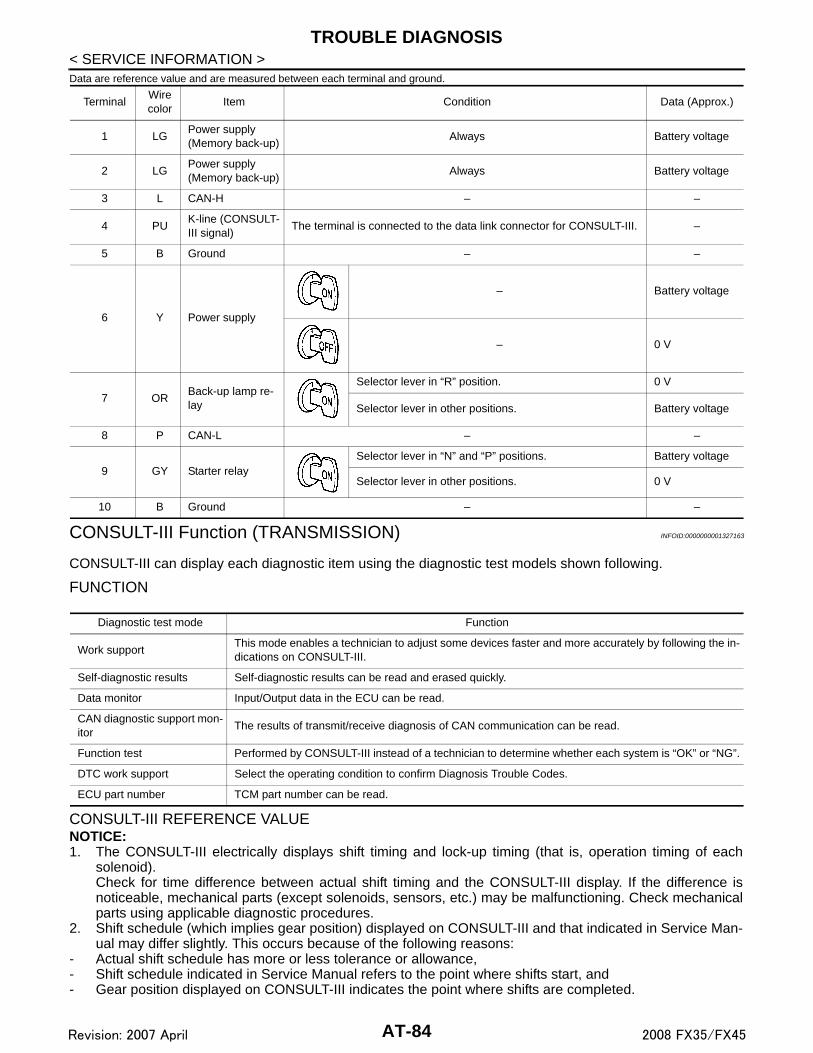
TROUBLE DIAGNOSIS
< SERVICE INFORMATION >Data are reference value and are measured between each terminal and ground.CONSULT-III Function (TRANSMISSION) INFOID:0000000001327163
CONSULT-III can display each diagnostic item using the diagnostic test models shown following.
FUNCTION
CONSULT-III REFERENCE VALUENOTICE:1. The CONSULT-III electrically displays shift timing and lock-up timing (that is, operation timing of each
solenoid).Check for time difference between actual shift timing and the CONSULT-III display. If the difference isnoticeable, mechanical parts (except solenoids, sensors, etc.) may be malfunctioning. Check mechanicalparts using applicable diagnostic procedures.
2. Shift schedule (which implies gear position) displayed on CONSULT-III and that indicated in Service Man-ual may differ slightly. This occurs because of the following reasons:
- Actual shift schedule has more or less tolerance or allowance,- Shift schedule indicated in Service Manual refers to the point where shifts start, and- Gear position displayed on CONSULT-III indicates the point where shifts are completed.
TerminalWire color
Item Condition Data (Approx.)
1 LGPower supply(Memory back-up)
Always Battery voltage
2 LGPower supply(Memory back-up)
Always Battery voltage
3 L CAN-H – –
4 PUK-line (CONSULT-III signal)
The terminal is connected to the data link connector for CONSULT-III. –
5 B Ground – –
6 Y Power supply
– Battery voltage
– 0 V
7 ORBack-up lamp re-lay
Selector lever in “R” position. 0 V
Selector lever in other positions. Battery voltage
8 P CAN-L – –
9 GY Starter relaySelector lever in “N” and “P” positions. Battery voltage
Selector lever in other positions. 0 V
10 B Ground – –
Diagnostic test mode Function
Work supportThis mode enables a technician to adjust some devices faster and more accurately by following the in-dications on CONSULT-III.
Self-diagnostic results Self-diagnostic results can be read and erased quickly.
Data monitor Input/Output data in the ECU can be read.
CAN diagnostic support mon-itor
The results of transmit/receive diagnosis of CAN communication can be read.
Function test Performed by CONSULT-III instead of a technician to determine whether each system is “OK” or “NG”.
DTC work support Select the operating condition to confirm Diagnosis Trouble Codes.
ECU part number TCM part number can be read.
AT-84Revision: 2007 April 2008 FX35/FX45

TROUBLE DIAGNOSIS
D
E
F
G
H
I
J
K
L
M
A
B
T
N
O
P
< SERVICE INFORMATION >
A
3. Display of solenoid valves on CONSULT-III changes at the start of shifting, while gear position is displayedupon completion of shifting (which is computed by TCM).
Item name Condition Display value (Approx.)
ATF TEMP SE 10°C (32°F) − 20°C (68°F) − 80°C (176°F)
3.3 − 2.7 − 0.9 V
ATF TEMP SE 2 3.3 − 2.5− 0.7 V
ATF TEMP 1 Ignition switch ONMeasured ATF temperature is dis-played.
TCC SOLENOID Lock-up is active 0.4 − 0.6 A
SLCT LVR POSI
Selector lever in “N” and “P” positions. N/P
Selector lever in “R” position. R
Selector lever in “D” position. D
VHCL/S SE-A/T During drivingApproximately matches the speedom-eter reading.
VEHICLE SPEED During drivingApproximately matches the speedom-eter reading.
ENGINE SPEED Engine runningClosely matches the tachometer read-ing.
LINE PRES SOL During driving 0.2 − 0.6 A
TURBINE REV During driving (lock-up ON)Approximately matches the engine speed.
VHCL/S SE-MTR During drivingApproximately matches the speedom-eter reading.
ATF PRES SW 2Low coast brake engaged. Refer to AT-18. ON
Low coast brake disengaged. Refer to AT-18. OFF
I/C SOLENOIDInput clutch disengaged. Refer to AT-18. 0.6 − 0.8 A
Input clutch engaged. Refer to AT-18. 0 − 0.05 A
FR/B SOLENOIDFront brake engaged. Refer to AT-18. 0.6 − 0.8 A
Front brake disengaged. Refer to AT-18. 0 − 0.05 A
D/C SOLENOIDDirect clutch disengaged. Refer to AT-18. 0.6 − 0.8 A
Direct clutch engaged. Refer to AT-18. 0 − 0.05 A
HLR/C SOLHigh and low reverse clutch disengaged. Refer to AT-18. 0.6 − 0.8 A
High and low reverse clutch engaged. Refer to AT-18. 0 − 0.05 A
ON OFF SOLLow coast brake engaged. Refer to AT-18. ON
Low coast brake disengaged. Refer to AT-18. OFF
MANU MODE SWManual shift gate position (neutral) ON
Other than the above OFF
NON M-MODE SWManual shift gate position OFF
Other than the above ON
UP SW LEVERSelector lever: + side ON
Other than the above OFF
DOWN SW LEVERSelector lever: - side ON
Other than the above OFF
STARTER RELAYSelector lever in “N” and “P” positions. ON
Selector lever in other positions. OFF
ACCELE POSIReleased accelerator pedal. 0.0/8
Fully depressed accelerator pedal. 8.0/8
AT-85Revision: 2007 April 2008 FX35/FX45

TROUBLE DIAGNOSIS
< SERVICE INFORMATION >SELF-DIAGNOSTIC RESULT MODEAfter performing “SELF-DIAGNOSTIC RESULT MODE”, place check marks for results on the AT-42, "How toPerform Trouble Diagnosis for Quick and Accurate Repair". Reference pages are provided following the items.
Display Items ListX: Applicable, —: Not applicable
CLSD THL POSReleased accelerator pedal. ON
Fully depressed accelerator pedal. OFF
W/O THL POSFully depressed accelerator pedal. ON
Released accelerator pedal. OFF
BRAKE SWDepressed brake pedal. ON.
Released brake pedal. OFF
GEAR During driving. 1,2,3,4,5,
Item name Condition Display value (Approx.)
Items (CONSULT-III screen terms)
Malfunction is detected when...
TCM self-di-agnosis
OBD-II (DTC)
Reference page
“TRANS-MISSION”
with CON-SULT-III
MIL indica-
tor lamp(*1), “ENGINE” with CON-SULT-III or
GST
CAN COMM CIR-CUIT
When TCM is not transmitting or receiving CAN communication sig-nal for 2 seconds or more.
U1000 U1000 AT-94
STARTER RELAY/CIRC
If this signal is ON other than in “P” or “N” position, this is judged to be a malfunction.(And if it is OFF in “P” or “N” position, this too is judged to be a mal-function.)
P0615 — AT-97
TCM TCM is malfunctioning. P0700 P0700 AT-101
PNP SW/CIRC• PNP switch 1-4 signals input with impossible pattern.• “P” position is detected from “N” position without any other posi-
tion being detected in between.P0705 P0705 AT-102
TURBINE REV S/CIRC
• TCM does not receive the proper voltage signal from the sensor.• TCM detects an irregularity only at position of 4th gear for turbine
revolution sensor 2.P0717 P0717 AT-106
VEH SPD SEN/CIR AT
• Signal from vehicle speed sensor A/T (Revolution sensor) not in-put due to cut line or the like.
• Unexpected signal input during running.• After ignition switch is turned ON, unexpected signal input from
vehicle speed sensor MTR before the vehicle starts moving.
P0720 P0720 AT-108
ENGINE SPEED SIG
TCM does not receive the CAN communication signal from the ECM.
P0725 P0725 AT-112
A/T 1ST GR FNCTN
A/T cannot shift to 1st gear. P0731 P0731 AT-114
A/T 2ND GR FNCTN
A/T cannot shift to 2nd gear. P0732 P0732 AT-116
A/T 3RD GR FNCTN
A/T cannot shift to 3rd gear. P0733 P0733 AT-118
A/T 4TH GR FNCTN
A/T cannot shift to 4th gear. P0734 P0734 AT-120
A/T 5TH GR FNCTN
A/T cannot shift to 5th gear. P0735 P0735 AT-122
TCC SOLENOID/CIRC
Normal voltage not applied to solenoid due to cut line, short, or the like.
P0740 P0740 AT-124
AT-86Revision: 2007 April 2008 FX35/FX45

TROUBLE DIAGNOSIS
D
E
F
G
H
I
J
K
L
M
A
B
T
N
O
P
< SERVICE INFORMATION >
A
*1: Refer to EC-71, "Malfunction Indicator Lamp (MIL)" (for VQ35DE engine) or EC-649, "Malfunction Indicator Lamp (MIL)" (for VK45DEengine.)
A/T TCC S/V FNCTN
• A/T cannot perform lock-up even if electrical circuit is good.• TCM detects as irregular by comparing difference value with slip
rotation.P0744 P0744(*2) AT-126
L/PRESS SOL/CIRC
• Normal voltage not applied to solenoid due to cut line, short, or the like.
• TCM detects as irregular by comparing target value with monitor value.
P0745 P0745 AT-128
TP SEN/CIRC A/TTCM does not receive the proper accelerator pedal position signals (input by CAN communication) from ECM.
P1705 P1705 AT-130
ATF TEMP SEN/CIRC
During running, the A/T fluid temperature sensor signal voltage is excessively high or low.
P1710 P0710 AT-132
VEH SPD SE/CIR-MTR
• Signal (CAN communication) from vehicle speed sensor MTR not input due to cut line or the like.
• Unexpected signal input during running.P1721 — AT-137
A/T INTERLOCKExcept during shift change, the gear position and ATF pressure switch states are monitored and comparative judgement made.
P1730 P1730 AT-139
A/T 1ST E/BRAK-ING
Each ATF pressure switch and solenoid current is monitored and if a pattern is detected having engine braking 1st gear other than in the M1 position, a malfunction is detected.
P1731 — AT-141
I/C SOLENOID/CIRC
• Normal voltage not applied to solenoid due to functional malfunc-tion, cut line, short, or the like.
• TCM detects as irregular by comparing target value with monitor value.
P1752 P1752 AT-143
FR/B SOLENOID/CIRC
• Normal voltage not applied to solenoid due to functional malfunc-tion, cut line, short, or the like.
• TCM detects as irregular by comparing target value with monitor value.
P1757 P1757 AT-145
D/C SOLENOID/CIRC
• Normal voltage not applied to solenoid due to cut line, short, or the like.
• TCM detects as irregular by comparing target value with monitor value.
P1762 P1762 AT-147
HLR/C SOL/CIRC
• Normal voltage not applied to solenoid due to functional malfunc-tion, cut line, short, or the like.
• TCM detects as irregular by comparing target value with monitor value.
P1767 P1767 AT-149
LC/B SOLENOID/CIRC
Normal voltage not applied to solenoid due to functional malfunction, cut line, short, or the like.
P1772 P1772 AT-151
LC/B SOLENOID FNCT
• TCM detects an improper voltage drop when it tries to operate the solenoid valve.
• Condition of ATF pressure switch 2 is different from monitor value, and relation between gear position and actual gear ratio is irregu-lar.
P1774 P1774(*2) AT-153
MANU MODE SW/CIRC
When an impossible pattern of switch signals is detected, a malfunc-tion is detected.
P1815 — AT-155
NO DTC IS DE-TECTED FUR-THER TESTING MAY BE RE-QUIRED
No NG item has been detected. X X —
Items (CONSULT-III screen terms)
Malfunction is detected when...
TCM self-di-agnosis
OBD-II (DTC)
Reference page
“TRANS-MISSION”
with CON-SULT-III
MIL indica-
tor lamp(*1), “ENGINE” with CON-SULT-III or
GST
AT-87Revision: 2007 April 2008 FX35/FX45

TROUBLE DIAGNOSIS
< SERVICE INFORMATION >*2: These malfunctions cannot be displayed MIL if another malfunction is assigned to MIL.DATA MONITOR MODE
Display Items List
X: Standard, —: Not applicable, : Option
Monitored item (Unit)
Select Monitor Item
RemarksECU IN-PUT SIG-
NALS
MAIN SIG-NALS
SELEC-TION FROM MENU
VHCL/S SE-A/T (km/h) X X Revolution sensor
VHCL/S SE-MTR (km/h) X —
ACCELE POSI (0.0/8) X — Accelerator pedal position signal
THROTTLE POSI (0.0/8) X X
Degree of opening for accelerator recognized by the TCMFor fail-safe operation, the specific value used for control is displayed.
CLSD THL POS (ON/OFF) X —Signal input with CAN communications
W/O THL POS (ON/OFF) X —
BRAKE SW (ON/OFF) X — Stop lamp switch
GEAR — XGear position recognized by the TCM updated after gear-shifting
ENGINE SPEED (rpm) X X
TURBINE REV (rpm) X X
OUTPUT REV (rpm) X X
GEAR RATIO — X
TC SLIP SPEED (rpm) — XDifference between engine speed and torque converter input shaft speed
F SUN GR REV (rpm) — —
F CARR GR REV (rpm) — —
ATF TEMP SE 1 (V) X —
ATF TEMP SE 2 (V) X —
ATF TEMP 1 (°C) — X
ATF TEMP 2 (°C) — X
BATTERY VOLT (V) X —
ATF PRES SW 1 (ON/OFF) X X (for FR/B solenoid)
ATF PRES SW 2 (ON/OFF) X X (for LC/B solenoid)
ATF PRES SW 3 (ON/OFF) X X (for I/C solenoid)
ATF PRES SW 5 (ON/OFF) X X (for D/C solenoid)
ATF PRES SW 6 (ON/OFF) X X (for HLR/C solenoid)
PNP SW 1 (ON/OFF) X —
PNP SW 2 (ON/OFF) X —
PNP SW 3 (ON/OFF) X —
PNP SW 4 (ON/OFF) X —
AT-88Revision: 2007 April 2008 FX35/FX45
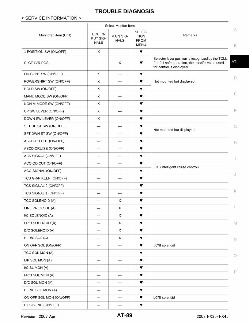
TROUBLE DIAGNOSIS
D
E
F
G
H
I
J
K
L
M
A
B
T
N
O
P
< SERVICE INFORMATION >
A
1 POSITION SW (ON/OFF) X —
SLCT LVR POSI — XSelector lever position is recognized by the TCM.For fail-safe operation, the specific value used for control is displayed.
OD CONT SW (ON/OFF) X —
Not mounted but displayed.POWERSHIFT SW (ON/OFF) X —
HOLD SW (ON/OFF) X —
MANU MODE SW (ON/OFF) X —
NON M-MODE SW (ON/OFF) X —
UP SW LEVER (ON/OFF) X —
DOWN SW LEVER (ON/OFF) X —
SFT UP ST SW (ON/OFF) — —Not mounted but displayed.
SFT DWN ST SW (ON/OFF) — —
ASCD-OD CUT (ON/OFF) — —
ASCD-CRUISE (ON/OFF) — —
ABS SIGNAL (ON/OFF) — —
ACC-OD CUT (ON/OFF) — —ICC (intelligent cruise control)
ACC-SIGNAL (ON/OFF) — —
TCS GR/P KEEP (ON/OFF) — —
TCS SIGNAL 2 (ON/OFF) — —
TCS SIGNAL 1 (ON/OFF) — —
TCC SOLENOID (A) — X
LINE PRES SOL (A) — X
I/C SOLENOID (A) — X
FR/B SOLENOID (A) — X
D/C SOLENOID (A) — X
HLR/C SOL (A) — X
ON OFF SOL (ON/OFF) — — LC/B solenoid
TCC SOL MON (A) — —
L/P SOL MON (A) — —
I/C SL MON (A) — —
FR/B SOL MON (A) — —
D/C SOL MON (A) — —
HLR/C SOL MON (A) — —
ON OFF SOL MON (ON/OFF) — — LC/B solenoid
P POSI IND (ON/OFF) — —
Monitored item (Unit)
Select Monitor Item
RemarksECU IN-PUT SIG-
NALS
MAIN SIG-NALS
SELEC-TION FROM MENU
AT-89Revision: 2007 April 2008 FX35/FX45

TROUBLE DIAGNOSIS
< SERVICE INFORMATION >R POSI IND (ON/OFF) — —
N POSI IND (ON/OFF) — —
D POSI IND (ON/OFF) — —
4TH POSI IND (ON/OFF) — —
3RD POSI IND (ON/OFF) — —
2ND POSI IND (ON/OFF) — —
1ST POSI IND (ON/OFF) — —
MANU MODE IND (ON/OFF) — —
POWER M LAMP (ON/OFF) — —
F-SAFE IND/L (ON/OFF) — —
ATF WARN LAMP (ON/OFF) — — Not mounted but displayed
BACK-UP LAMP (ON/OFF) — —
STARTER RELAY (ON/OFF) — —
PNP SW3 MON (ON/OFF) — —
C/V CLB ID1 — —
C/V CLB ID2 — —
C/V CLB ID3 — —
UNIT CLB ID1 — —
UNIT CLB ID2 — —
UNIT CLB ID3 — —
TRGT GR RATIO — —
TRGT PRES TCC (kPa) — —
TRGT PRES L/P (kPa) — —
TRGT PRES I/C (kPa) — —
TRGT PRE FR/B (kPa) — —
TRGT PRES D/C (kPa) — —
TRG PRE HLR/C (kPa) — —
SHIFT PATTERN — —
DRV CST JUDGE — —
START RLY MON — —
NEXT GR POSI — —
SHIFT MODE — —
MANU GR POSI — —
VEHICLE SPEED (km/h) — X Vehicle speed recognized by the TCM.
Monitored item (Unit)
Select Monitor Item
RemarksECU IN-PUT SIG-
NALS
MAIN SIG-NALS
SELEC-TION FROM MENU
AT-90Revision: 2007 April 2008 FX35/FX45

TROUBLE DIAGNOSIS
D
E
F
G
H
I
J
K
L
M
A
B
T
N
O
P
< SERVICE INFORMATION >
A
DTC WORK SUPPORT MODE
Display Items List
Diagnosis Procedure without CONSULT-III INFOID:0000000001327164
OBD-II SELF-DIAGNOSTIC PROCEDURE (WITH GST)Refer to EC-125, "Generic Scan Tool (GST) Function" (for VQ35DE) or EC-704, "Generic Scan Tool (GST)Function" (for VK45DE).
OBD-II SELF-DIAGNOSTIC PROCEDURE (NO TOOLS)Refer to EC-71, "Malfunction Indicator Lamp (MIL)" (for VQ35DE) or EC-649, "Malfunction Indicator Lamp(MIL)" (for VK45DE).
TCM SELF-DIAGNOSTIC PROCEDURE (NO TOOLS)
DescriptionWhen the ignition switch is turned ON, the indicator lamp lights up for 2 seconds. As a method for locating thesuspect circuit, when the self-diagnostics start signal is input, the memory for the malfunction location is outputand the A/T CHECK indicator lamp flashes to display the corresponding DTC.
Diagnostic Procedure
Voltage (V) — —Displays the value measured by the voltage probe.
Frequency (Hz) — —
The value measured by the pulse probe is dis-played.
DUTY-HI (high) (%) — —
DUTY-LOW (low) (%) — —
PLS WIDTH-HI (ms) — —
PLS WIDTH-LOW (ms) — —
Monitored item (Unit)
Select Monitor Item
RemarksECU IN-PUT SIG-
NALS
MAIN SIG-NALS
SELEC-TION FROM MENU
DTC work support item Description Check item
1ST GR FUNCTN P0731
Following items for “1st gear function” can be confirmed.• Self-diagnosis status (whether the diagnosis is being performed
or not)• Self-diagnostic results (OK or NG)
• Input clutch solenoid valve• Front brake solenoid valve• Direct clutch solenoid valve• High and low reverse clutch
solenoid valve• Each clutch• Hydraulic control circuit
2ND GR FUNCTN P0732
Following items for “2nd gear function” can be confirmed.• Self-diagnosis status (whether the diagnosis is being performed
or not)• Self-diagnostic results (OK or NG)
3RD GR FUNCTN P0733
Following items for “3rd gear function” can be confirmed.• Self-diagnosis status (whether the diagnosis is being performed
or not)• Self-diagnostic results (OK or NG)
4TH GR FUNCTN P0734
Following items for “4th gear function” can be confirmed.• Self-diagnosis status (whether the diagnosis is being performed
or not)• Self-diagnostic results (OK or NG)
5TH GR FUNCTN P0735
Following items for “5th gear function” can be confirmed.• Self-diagnosis status (whether the diagnosis is being performed
or not)• Self-diagnostic results (OK or NG)
AT-91Revision: 2007 April 2008 FX35/FX45
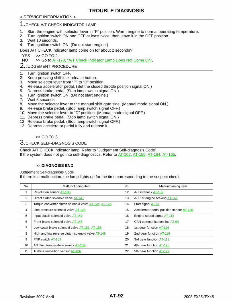
TROUBLE DIAGNOSIS
< SERVICE INFORMATION >1.CHECK A/T CHECK INDICATOR LAMP
1. Start the engine with selector lever in “P” position. Warm engine to normal operating temperature.2. Turn ignition switch ON and OFF at least twice, then leave it in the OFF position. 3. Wait 10 seconds.4. Turn ignition switch ON. (Do not start engine.)Does A/T CHECK indicator lamp come on for about 2 seconds?YES >> GO TO 2.NO >> Go to AT-170, "A/T Check Indicator Lamp Does Not Come On".
2.JUDGEMENT PROCEDURE
1. Turn ignition switch OFF.2. Keep pressing shift lock release button.3. Move selector lever from “P” to “D” position.4. Release accelerator pedal. (Set the closed throttle position signal ON.)5. Depress brake pedal. (Stop lamp switch signal ON.)6. Turn ignition switch ON. (Do not start engine.)7. Wait 3 seconds.8. Move the selector lever to the manual shift gate side. (Manual mode signal ON.)9. Release brake pedal. (Stop lamp switch signal OFF.)10. Move the selector lever to “D” position. (Manual mode signal OFF.)11. Depress brake pedal. (Stop lamp switch signal ON.)12. Release brake pedal. (Stop lamp switch signal OFF.)13. Depress accelerator pedal fully and release it.
>> GO TO 3.
3.CHECK SELF-DIAGNOSIS CODE
Check A/T CHECK indicator lamp. Refer to "Judgement Self-diagnosis Code".If the system does not go into self-diagnostics. Refer to AT-102, AT-155, AT-164, AT-165.
>> DIAGNOSIS END
Judgement Self-diagnosis CodeIf there is a malfunction, the lamp lights up for the time corresponding to the suspect circuit.
No. Malfunctioning item No. Malfunctioning item
1 Revolution sensor AT-108 12 A/T interlock AT-139
2 Direct clutch solenoid valve AT-147 13 A/T 1st engine braking AT-141
3 Torque converter clutch solenoid valve AT-124, AT-126 14 Start signal AT-97
4 Line pressure solenoid valve AT-128 15 Accelerator pedal position sensor AT-130
5 Input clutch solenoid valve AT-143 16 Engine speed signal AT-112
6 Front brake solenoid valve AT-145 17 CAN communication line AT-94
7 Low coast brake solenoid valve AT-151, AT-153 18 1st gear function AT-114
8 High and low reverse clutch solenoid valve AT-149 19 2nd gear function AT-116
9 PNP switch AT-102 20 3rd gear function AT-118
10 A/T fluid temperature sensor AT-132 21 4th gear function AT-120
11 Turbine revolution sensor AT-106 22 5th gear function AT-122
AT-92Revision: 2007 April 2008 FX35/FX45

TROUBLE DIAGNOSIS
D
E
F
G
H
I
J
K
L
M
A
B
T
N
O
P
< SERVICE INFORMATION >
A
Erase Self-diagnosis• In order to make it easier to find the cause of hard-to-duplicate malfunctions, malfunction information is
stored into the control unit as necessary during use by the user. This memory is not erased no matter howmany times the ignition switch is turned ON and OFF.
• However, this information is erased by turning ignition switch “OFF” after performing self-diagnostics or byerasing the memory using the CONSULT-III.
SCIA8153E
AT-93Revision: 2007 April 2008 FX35/FX45

DTC U1000 CAN COMMUNICATION LINE
< SERVICE INFORMATION >DTC U1000 CAN COMMUNICATION LINE
Description INFOID:0000000001327165
CAN (Controller Area Network) is a serial communication line for real time application. It is an on-vehicle mul-tiplex communication line with high data communication speed and excellent malfunction detection ability.Many electronic control units are equipped onto a vehicle, and each control unit shares information and linkswith other control units during operation (not independent). In CAN communication, control units are con-nected with 2 communication lines (CAN-H line, CAN-L line) allowing a high rate of information transmissionwith less wiring. Each control unit transmits/receives data but selectively reads required data only.
On Board Diagnosis Logic INFOID:0000000001327166
Diagnostic trouble code “U1000 CAN COMM CIRCUIT” with CONSULT-III or 17th judgement flicker withoutCONSULT-III is detected when TCM cannot communicate to other control units.
Possible Cause INFOID:0000000001327167
Harness or connectors(CAN communication line is open or shorted.)
DTC Confirmation Procedure INFOID:0000000001327168
NOTE:If “DTC Confirmation Procedure” has been previously performed, always turn ignition switch OFF andwait at least 10 seconds before performing the next test.After the repair, perform the following procedure to confirm the malfunction is eliminated.
WITH CONSULT-III1. Turn ignition switch ON. 2. Select “ECU INPUT SIGNALS” or “MAIN SIGNALS” in “DATA MONITOR” mode for “TRANSMISSION”
with CONSULT-III.3. Start engine and wait for at least 6 seconds.4. If DTC is detected, go to AT-96, "Diagnosis Procedure".
WITH GSTFollow the procedure “WITH CONSULT-III”.
AT-94Revision: 2007 April 2008 FX35/FX45

DTC U1000 CAN COMMUNICATION LINE
D
E
F
G
H
I
J
K
L
M
A
B
T
N
O
P
< SERVICE INFORMATION >
A
Wiring Diagram - AT - CAN INFOID:0000000001327169
TCWM0496E
AT-95Revision: 2007 April 2008 FX35/FX45

DTC U1000 CAN COMMUNICATION LINE
< SERVICE INFORMATION >TCM terminals and data are reference value. Measured between each terminal and ground.Diagnosis Procedure INFOID:0000000001327170
1.CHECK CAN COMMUNICATION CIRCUIT
With CONSULT-III1. Turn ignition switch ON and start engine.2. Select “SELF-DIAG RESULTS” mode for “TRANSMISSION” with CONSULT-III.Is the “U1000 CAN COMM CIRCUIT” indicated?YES >> Go to LAN section. Refer to LAN-43, "CAN System Specification Chart".NO >> INSPECTION END
TerminalWire color
Item Condition Data (Approx.)
3 L CAN-H – –
8 P CAN-L – –
AT-96Revision: 2007 April 2008 FX35/FX45

DTC P0615 START SIGNAL CIRCUIT
D
E
F
G
H
I
J
K
L
M
A
B
T
N
O
P
< SERVICE INFORMATION >
A
DTC P0615 START SIGNAL CIRCUIT
Description INFOID:0000000001327171
TCM prohibits cranking other than at “P” or “N” position.
CONSULT-III Reference Value in Data Monitor Mode INFOID:0000000001327172
On Board Diagnosis Logic INFOID:0000000001327173
Diagnostic trouble code “P0615 STARTER RELAY/CIRC” with CONSULT-III or 14th judgement flicker withoutCONSULT-III is detected when starter relay is switched ON other than at “P” or “N” position. (Or whenswitched OFF at “P” or “N” position).
Possible Cause INFOID:0000000001327174
• Harness or connectors(Starter relay and TCM circuit is open or shorted.)
• Starter relay circuit
DTC Confirmation Procedure INFOID:0000000001327175
CAUTION:Always drive vehicle at a safe speed.NOTE:If “DTC Confirmation Procedure” has been previously performed, always turn ignition switch OFF andwait at least 10 seconds before performing the next test.After the repair, perform the following procedure to confirm the malfunction is eliminated.
WITH CONSULT-III1. Turn ignition switch ON.2. Select “SELECTION FROM MENU” in “DATA MONITOR” mode for “TRANSMISSION” with CONSULT-III
and check monitor “STARTER RELAY” ON/OFF.3. Start engine.4. Drive vehicle for at least 2 consecutive seconds.5. If DTC is detected, go to AT-99, "Diagnosis Procedure".
Item name Condition Display value
STARTER RELAYSelector lever in “N” and “P” positions. ON
Selector lever in other positions. OFF
AT-97Revision: 2007 April 2008 FX35/FX45

DTC P0615 START SIGNAL CIRCUIT
< SERVICE INFORMATION >Wiring Diagram - AT - STSIG INFOID:0000000001327176
TCM terminals and data are reference value. Measured between each terminal and ground.TCWM0247E
TerminalWire color
Item Condition Data (Approx.)
9 GY Starter relaySelector lever in “N” and “P” positions. Battery voltage
Selector lever in other positions. 0 V
AT-98Revision: 2007 April 2008 FX35/FX45

DTC P0615 START SIGNAL CIRCUIT
D
E
F
G
H
I
J
K
L
M
A
B
T
N
O
P
< SERVICE INFORMATION >
A
Diagnosis Procedure INFOID:0000000001327177
1.CHECK STARTER RELAY
With CONSULT-III1. Turn ignition switch ON.2. Select “SELECTION FROM MENU” in “DATA MONITOR” mode for “TRANSMISSION” with CONSULT-III
and check monitor “STARTER RELAY” ON/OFF.
Without CONSULT-III1. Turn ignition switch ON.2. Check voltage between the IPDM E/R connector and ground.
OK or NGOK >> GO TO 5.NG >> GO TO 2.
2. CHECK HARNESS BETWEEN A/T ASSEMBLY HARNESS CONNECTOR AND IPDM E/R CONNECTOR
1. Turn ignition switch OFF.2. Disconnect A/T assembly harness connector and IPDM E/R connector.3. Check continuity between A/T assembly harness connector and
IPDM E/R connector.
4. If OK, check harness for short to ground and short to power.5. Reinstall any part removed.OK or NGOK >> GO TO 3.NG >> Repair open circuit or short to ground or short to power in harness or connectors.
3.CHECK TERMINAL CORD ASSEMBLY
1. Remove control valve with TCM. Refer to AT-215, "Control Valve with TCM and A/T Fluid TemperatureSensor 2".
2. Disconnect A/T assembly harness connector and TCM connector.
Item name Condition Display value
STARTER RELAYSelector lever in “N” and “P” positions. ON
Selector lever in other positions. OFF
Name Connector Terminal Shift position Voltage (Approx.)
Starter re-lay
E9 53 - Ground“N” and “P” Battery voltage
“R” and “D” 0 V
SCIA2103E
Item Connector Terminal Continuity
A/T assembly harness con-nector
F44 9 Yes
IPDM E/R connector E9 53
SCIA5439E
AT-99Revision: 2007 April 2008 FX35/FX45

DTC P0615 START SIGNAL CIRCUIT
< SERVICE INFORMATION >3. Check continuity between A/T assembly harness connector ter-minal and TCM connector terminal.
4. If OK, check harness for short to ground and short to power.5. Reinstall any part removed.OK or NGOK >> GO TO 4.NG >> Replace open circuit or short to ground and short to power in harness or connectors.
4.DETECT MALFUNCTIONING ITEM
Check the following.• Starter relay, Refer to SC-8.• IPDM E/R, Refer to PG-17.OK or NGOK >> Replace the control valve with TCM. Refer to AT-215, "Control Valve with TCM and A/T Fluid Tem-
perature Sensor 2".NG >> Repair or replace damaged parts.
5.CHECK DTC
Perform AT-97, "DTC Confirmation Procedure". OK or NGOK >> INSPECTION ENDNG >> GO TO 2.
Item Connector Terminal Continuity
A/T assembly harness con-nector
F44 9 Yes
TCM connector F502 8
SCIA5440E
AT-100Revision: 2007 April 2008 FX35/FX45

DTC P0700 TCM
D
E
F
G
H
I
J
K
L
M
A
B
T
N
O
P
< SERVICE INFORMATION >
A
DTC P0700 TCM
Description INFOID:0000000001327178
The TCM consists of a microcomputer and connectors for signal input and output and for power supply. TheTCM controls the A/T.
On Board Diagnosis Logic INFOID:0000000001327179
Diagnostic trouble code “P0700 TCM” with CONSULT-III is detected when TCM is malfunctioning.
Possible Cause INFOID:0000000001327180
TCM.
DTC Confirmation Procedure INFOID:0000000001327181
NOTE:If “DTC Confirmation Procedure” has been previously performed, always turn ignition switch OFF andwait at least 10 seconds before performing the next test.After the repair, perform the following procedure to confirm the malfunction is eliminated.
WITH CONSULT-III1. Turn ignition switch ON.2. Select “ECU INPUT SIGNALS” or “MAIN SIGNALS” in “DATA MONITOR” mode for “TRANSMISSION”
with CONSULT-III.3. Touch “START”.4. Start engine.5. Run engine for at least 2 consecutive seconds at idle speed.6. If DTC is detected, go to AT-101, "Diagnosis Procedure".
WITH GSTFollow the procedure “WITH CONSULT-III”.
Diagnosis Procedure INFOID:0000000001327182
1.CHECK DTC
With CONSULT-III1. Turn ignition switch ON.2. Select “SELF DIAG RESULTS” mode for “TRANSMISSION” with CONSULT-III.3. Touch “ERASE”.4. Turn ignition switch OFF and wait at least 10 seconds.5. Perform AT-101, "DTC Confirmation Procedure".Is the “P0700 TCM” displayed again?YES >> Replace the control valve with TCM. Refer to AT-215, "Control Valve with TCM and A/T Fluid Tem-
perature Sensor 2".NO >> INSPECTION END
AT-101Revision: 2007 April 2008 FX35/FX45

DTC P0705 PARK/NEUTRAL POSITION SWITCH
< SERVICE INFORMATION >DTC P0705 PARK/NEUTRAL POSITION SWITCH
Description INFOID:0000000001327183
• The PNP switch includes a transmission range switch.• The transmission range switch detects the selector lever position and sends a signal to the TCM.
CONSULT-III Reference Value in Data Monitor Mode INFOID:0000000001327184
On Board Diagnosis Logic INFOID:0000000001327185
Diagnostic trouble code “P0705 PNP SW/CIRC” with CONSULT-III or 9th judgement flicker without CON-SULT-III is detected under the following conditions.• When TCM does not receive the correct voltage signal from the PNP switches 1, 2, 3 and 4 based on the
gear position.• When no other position but “P” position is detected from “N” position.
Possible Cause INFOID:0000000001327186
• Harness or connectors(PNP switches 1, 2, 3 and 4 and TCM circuit is open or shorted.)
• PNP switches 1, 2, 3 and 4
DTC Confirmation Procedure INFOID:0000000001327187
CAUTION:Always drive vehicle at a safe speed.NOTE:If “DTC Confirmation Procedure” has been previously performed, always turn ignition switch OFF andwait at least 10 seconds before performing the next test.After the repair, perform the following procedure to confirm the malfunction is eliminated.
WITH CONSULT-III1. Turn ignition switch ON.2. Select “ECU INPUT SIGNALS” or “MAIN SIGNALS” in “DATA MONITOR” mode for “TRANSMISSION”
with CONSULT-III.3. Touch “START”.4. Start engine.5. Drive vehicle and maintain the following conditions for at least 2 consecutive seconds.
ACCELE POSI: More than 1.0/86. If DTC is detected, go to AT-103, "Diagnosis Procedure".
WITH GSTFollow the procedure “WITH CONSULT-III”.
Item name Condition Display value
SLCT LVR POSI
Selector lever in “N” and “P” positions. N/P
Selector lever in “R” position. R
Selector lever in “D” position. D
AT-102Revision: 2007 April 2008 FX35/FX45

DTC P0705 PARK/NEUTRAL POSITION SWITCH
D
E
F
G
H
I
J
K
L
M
A
B
T
N
O
P
< SERVICE INFORMATION >
A
Wiring Diagram - AT - PNP/SW INFOID:0000000001327188
Diagnosis Procedure INFOID:0000000001327189
1.CHECK PNP SW CIRCUIT
With CONSULT-III1. Turn ignition switch ON.
TCWM0248E
AT-103Revision: 2007 April 2008 FX35/FX45

DTC P0705 PARK/NEUTRAL POSITION SWITCH
< SERVICE INFORMATION >2. Select “SELECTION FROM MENU” in “DATA MONITOR” mode for “TRANSMISSION” with CONSULT-III.3. Check if correct selector lever position (N/P, R or D) is displayed as selector lever is moved into each posi-tion.
OK or NGOK >> GO TO 5.NG >> GO TO 2.
2.CHECK TCM POWER SUPPLY AND GROUND CIRCUIT
Check TCM power supply and ground circuit. Refer to AT-160.OK or NGOK >> GO TO 3.NG >> Repair or replace damaged parts.
3.DETECT MALFUNCTIONING ITEM
Check A/T assembly harness connector pin terminals for damage or loose connection with harness connector.OK or NGOK >> GO TO 4.NG >> Repair or replace damaged parts.
4.CHECK SUB-HARNESS
1. Remove control valve with TCM. Refer to AT-215, "Control Valve with TCM and A/T Fluid TemperatureSensor 2".
2. Disconnect park/neutral position switch connector and TCM connector.3. Check continuity between park/neutral position switch connector
terminals and TCM connector terminals.
4. If OK, check harness for short to ground and short to power.5. Reinstall any part removed.OK or NGOK >> Replace the control valve with TCM. Refer to AT-215, "Control Valve with TCM and A/T Fluid Tem-
perature Sensor 2".NG >> Replace open circuit or short to ground and short to power in harness or connectors.
5.CHECK DTC
Perform AT-102, "DTC Confirmation Procedure".OK or NG
Item name Condition Display value
SLCT LVR POSI
Selector lever in “N” and “P” positions. N/P
Selector lever in “R” position. R
Selector lever in “D” position. D
Item Connector Terminal Continuity
Park/neutral position switch connector
F505 1Yes
TCM connector F503 13
Park/neutral position switch connector
F505 2 Yes
TCM connector F503 11
Park/neutral position switch connector
F505 3Yes
TCM connector F503 12
Park/neutral position switch connector
F505 5Yes
TCM connector F503 14
SCIA5457E
AT-104Revision: 2007 April 2008 FX35/FX45

DTC P0705 PARK/NEUTRAL POSITION SWITCH
D
E
F
G
H
I
J
K
L
M
A
B
T
N
O
P
< SERVICE INFORMATION >
A
OK >> INSPECTION ENDNG >> GO TO 2.
AT-105Revision: 2007 April 2008 FX35/FX45

DTC P0717 TURBINE REVOLUTION SENSOR
< SERVICE INFORMATION >DTC P0717 TURBINE REVOLUTION SENSOR
Description INFOID:0000000001327190
The turbine revolution sensor detects input shaft rpm (revolutions per minute). It is located on the input side ofthe automatic transmission. Monitors revolution of sensor 1 and sensor 2 for non-standard conditions.
CONSULT-III Reference Value in Data Monitor Mode INFOID:0000000001327191
On Board Diagnosis Logic INFOID:0000000001327192
Diagnostic trouble code “P0717 TURBINE REV S/CIRC” with CONSULT-III or 11th judgement flicker withoutCONSULT-III is detected under the following conditions.• When TCM does not receive the proper voltage signal from the sensor.• When TCM detects an irregularity only at position of 4th gear for turbine revolution sensor 2.
Possible Cause INFOID:0000000001327193
• Harness or connectors(Sensor circuit is open or shorted.)
• Turbine revolution sensor 1 and/or 2
DTC Confirmation Procedure INFOID:0000000001327194
CAUTION:• Always drive vehicle at a safe speed.• Be careful not to rev engine into the red zone on the tachometer. NOTE:If “DTC Confirmation Procedure” has been previously performed, always turn ignition switch OFF andwait at least 10 seconds before performing the next test.After the repair, perform the following procedure to confirm the malfunction is eliminated.
WITH CONSULT-III1. Turn ignition switch ON.2. Select “SELECTION FROM MENU” in “DATA MONITOR” mode for “TRANSMISSION” with CONSULT-III
and check monitor “VHCL/S SE-A/T”, “ENGINE SPEED”, “ACCELE POSI”, “SLCT LVR POSI” and“GEAR”.
3. Touch “START”.4. Start engine and maintain the following conditions for at least 5 consecutive seconds.
VHCL/S SE-A/T: 40 km/h (25 MPH) or moreENGINE SPEED: 1,500 rpm or moreACCELE POSI: More than 0.5/8SLCT LVR POSI: “D” position GEAR (Turbine revolution sensor 1): “4” or “5” positionGEAR (Turbine revolution sensor 2): All positionsDriving location: Driving the vehicle uphill (increased engine load) will help maintain the drivingconditions required for this test.
5. If DTC is detected, go to AT-106, "Diagnosis Procedure".
WITH GSTFollow the procedure “WITH CONSULT-III”.
Diagnosis Procedure INFOID:0000000001327195
1.CHECK INPUT SIGNAL
With CONSULT-III1. Start engine.2. Select “ECU INPUT SIGNALS” in “DATA MONITOR” mode for “TRANSMISSION” with CONSULT-III.
Item name Condition Display value
TURBINE REV During driving (lock-up ON) Approximately matches the engine speed.
AT-106Revision: 2007 April 2008 FX35/FX45

DTC P0717 TURBINE REVOLUTION SENSOR
D
E
F
G
H
I
J
K
L
M
A
B
T
N
O
P
< SERVICE INFORMATION >
A
3. Vehicle start and read out the value of “TURBINE REV”.
OK or NGOK >> GO TO 4.NG >> GO TO 2.
2.CHECK TCM POWER SUPPLY AND GROUND CIRCUIT
Check TCM power supply and ground circuit. Refer to AT-160.OK or NGOK >> GO TO 3.NG >> Repair or replace damaged parts.
3.DETECT MALFUNCTIONING ITEM
Check A/T assembly harness connector pin terminals for damage or loose connection with harness connector.OK or NGOK >> Replace the control valve with TCM. Refer to AT-215, "Control Valve with TCM and A/T Fluid Tem-
perature Sensor 2".NG >> Repair or replace damaged parts.
4.CHECK DTC
Perform AT-106, "DTC Confirmation Procedure".OK or NGOK >> INSPECTION ENDNG >> GO TO 2.
Item name Condition Display value (rpm)
TURBINE REV During driving (lock-up ON) Approximately matches the engine speed.
AT-107Revision: 2007 April 2008 FX35/FX45

DTC P0720 VEHICLE SPEED SENSOR A/T (REVOLUTION SENSOR)
< SERVICE INFORMATION >DTC P0720 VEHICLE SPEED SENSOR A/T (REVOLUTION SENSOR)
Description INFOID:0000000001327196
The revolution sensor detects the revolution of the parking gear and emits a pulse signal. The pulse signal issent to the TCM which converts it into vehicle speed.
CONSULT-III Reference Value in Data Monitor Mode INFOID:0000000001327197
On Board Diagnosis Logic INFOID:0000000001327198
Diagnostic trouble code “P0720 VEH SPD SEN/CIR AT” with CONSULT-III or 1st judgement flicker withoutCONSULT-III is detected under the following conditions.• When TCM does not receive the proper voltage signal from the sensor.• After ignition switch is turned ON, irregular signal input from vehicle speed sensor MTR before the vehicle
starts moving.
Possible Cause INFOID:0000000001327199
• Harness or connectors(Sensor circuit is open or shorted.)
• Revolution sensor• Vehicle speed sensor MTR
DTC Confirmation Procedure INFOID:0000000001327200
CAUTION:• Always drive vehicle at a safe speed.• Be careful not to rev engine into the red zone on the tachometer.NOTE:If “DTC Confirmation Procedure” has been previously performed, always turn ignition switch OFF andwait at least 10 seconds before performing the next test.After the repair, perform the following procedure to confirm the malfunction is eliminated.
WITH CONSULT-III1. Turn ignition switch ON.2. Select “ECU INPUT SIGNALS” in “DATA MONITOR” mode for “TRANSMISSION” with CONSULT-III.3. Touch “START”.4. Drive vehicle and check for an increase of “VHCL/S SE-A/T” value in response to “VHCL/S SE-MTR”
value.If the check result is NG, go to AT-110, "Diagnosis Procedure".If the check result is OK, go to following step.
5. Select “SELECTION FROM MENU” in “DATA MONITOR” mode for “TRANSMISSION” with CONSULT-IIIand check monitor “VHCL/S SE-A/T”, “ACCELE POSI”, “ENGINE SPEED” and “SLCT LVR POSI”.
6. Start engine and maintain the following conditions for at least 5 consecutive seconds.VHCL/S SE-A/T: 30 km/h (19 MPH) or moreACCELE POSI: More than 1.0/8SLCT LVR POSI: “D” position Driving location: Driving the vehicle uphill (increased engine load) will help maintain the drivingconditions required for this test.If the check result is NG, go to AT-110, "Diagnosis Procedure".If the check result is OK, go to following step.
7. Maintain the following conditions for at least 5 consecutive seconds.ENGINE SPEED: 3,500 rpm or moreACCELE POSI: More than 1.0/8SLCT LVR POSI: “D” positionDriving location: Driving the vehicle uphill (increased engine load) will help maintain the drivingconditions required for this test.
Item name Condition Display value
VHCL/S SE-A/T During driving Approximately matches the speedometer reading.
AT-108Revision: 2007 April 2008 FX35/FX45

DTC P0720 VEHICLE SPEED SENSOR A/T (REVOLUTION SENSOR)
D
E
F
G
H
I
J
K
L
M
A
B
T
N
O
P
< SERVICE INFORMATION >
A
8. If DTC is detected, go to AT-110, "Diagnosis Procedure".
WITH GSTFollow the procedure “WITH CONSULT-III”.
Wiring Diagram - AT - VSSA/T INFOID:0000000001327201
TCWM0249E
AT-109Revision: 2007 April 2008 FX35/FX45

DTC P0720 VEHICLE SPEED SENSOR A/T (REVOLUTION SENSOR)
< SERVICE INFORMATION >Diagnosis Procedure INFOID:0000000001327202
1.CHECK INPUT SIGNAL
With CONSULT-III1. Turn ignition switch ON.2. Select “ECU INPUT SIGNALS” in “DATA MONITOR” mode for “TRANSMISSION” with CONSULT-III.3. Start engine.4. Read out the value of “VHCL/S SE-A/T” while driving.
Check the value changes according to driving speed.
OK or NGOK >> GO TO 6.NG >> GO TO 2.
2.CHECK TCM POWER SUPPLY AND GROUND CIRCUIT
Check TCM power supply and ground circuit. Refer to AT-160.OK or NGOK >> GO TO 3.NG >> Repair or replace damaged parts.
3.DETECT MALFUNCTIONING ITEM
Check A/T assembly harness connector pin terminals for damage or loose connection with harness connector.OK or NGOK >> GO TO 4.NG >> Repair or replace damaged parts.
4.CHECK SUB-HARNESS
1. Remove control valve with TCM. Refer to AT-215, "Control Valve with TCM and A/T Fluid TemperatureSensor 2".
2. Disconnect park/neutral position switch connector and TCM connector.3. Check continuity between park/neutral position switch connector
terminals and TCM connector terminals.
4. If OK, check harness for short to ground and short to power.5. Reinstall any part removed.OK or NGOK >> GO TO 5.NG >> Replace open circuit or short to ground and short to power in harness or connectors.
5.REPLACE THE REVOLUTION SENSOR AND CHECK DTC
1. Replace the revolution sensor. Refer to AT-233, "Revolution Sensor Component (2WD Models Only)"(2WD models) or AT-267, "Disassembly", AT-249, "Component" (AWD models).
Item name Condition Display value
VHCL/S SE-A/T During drivingApproximately matches the speedometer reading.
Item Connector Terminal Continuity
Park/neutral position switch connector
F505 8 Yes
TCM connector F503 20
Park/neutral position switch connector
F505 9Yes
TCM connector F503 17
Park/neutral position switch connector
F505 10Yes
TCM connector F503 16
SCIA5458E
AT-110Revision: 2007 April 2008 FX35/FX45

DTC P0720 VEHICLE SPEED SENSOR A/T (REVOLUTION SENSOR)
D
E
F
G
H
I
J
K
L
M
A
B
T
N
O
P
< SERVICE INFORMATION >
A
2. Perform AT-108, "DTC Confirmation Procedure".OK or NGOK >> INSPECTION ENDNG >> Replace the control valve with TCM. Refer to AT-215, "Control Valve with TCM and A/T Fluid Tem-
perature Sensor 2".
6.CHECK DTC
Perform AT-108, "DTC Confirmation Procedure".OK or NGOK >> INSPECTION ENDNG >> GO TO 2.
AT-111Revision: 2007 April 2008 FX35/FX45

DTC P0725 ENGINE SPEED SIGNAL
< SERVICE INFORMATION >DTC P0725 ENGINE SPEED SIGNAL
Description INFOID:0000000001327203
The engine speed signal is sent from the ECM to the TCM with CAN communication.
CONSULT-III Reference Value in Data Monitor Mode INFOID:0000000001327204
On Board Diagnosis Logic INFOID:0000000001327205
Diagnostic trouble code “P0725 ENGINE SPEED SIG” with CONSULT-III or 16th judgement flicker withoutCONSULT-III is detected when TCM does not receive the ignition signal from ECM during engine cranking orrunning.
Possible Cause INFOID:0000000001327206
Harness or connectors(ECM to TCM circuit is open or shorted.)
DTC Confirmation Procedure INFOID:0000000001327207
CAUTION:Always drive vehicle at a safe speed.NOTE:If “DTC Confirmation Procedure” has been previously performed, always turn ignition switch OFF andwait at least 10 seconds before performing the next test.After the repair, perform the following procedure to confirm the malfunction is eliminated.
WITH CONSULT-III1. Turn ignition switch ON.2. Select “SELECTION FROM MENU” in “DATA MONITOR” mode for “TRANSMISSION” with CONSULT-III
and check monitor “VHCL/S SE-A/T”, “ACCELE POSI” and “SLCT LVR POSI”.3. Touch “START”.4. Start engine and maintain the following conditions for at least 10 consecutive seconds.
VHCL/S SE-A/T: 10 km/h (6 MPH) or moreACCELE POSI: More than 1.0/8SLCT LVR POSI: “D” position
5. If DTC is detected, go to AT-112, "Diagnosis Procedure".
Diagnosis Procedure INFOID:0000000001327208
1.CHECK CAN COMMUNICATION LINE
With CONSULT-III• Perform the self-diagnosis.
Without CONSULT-III• Perform the self-diagnosis. Refer to AT-91, "Diagnosis Procedure without CONSULT-III".Is a malfunction in the CAN communication indicated in the results?YES >> Check CAN communication line. Refer to AT-94.NO >> GO TO 2.
2.CHECK DTC WITH TCM
With CONSULT-III1. Start engine.2. Select “ECU INPUT SIGNALS” in “DATA MONITOR” mode for “TRANSMISSION” with CONSULT-III.
Item name Condition Display value
ENGINE SPEED Engine running Closely matches the tachometer reading.
AT-112Revision: 2007 April 2008 FX35/FX45

DTC P0725 ENGINE SPEED SIGNAL
D
E
F
G
H
I
J
K
L
M
A
B
T
N
O
P
< SERVICE INFORMATION >
A
3. While monitoring engine speed, check for engine speed change corresponding to wide-open throttle posi-tion signal.
OK or NGOK >> GO TO 3.NG >> Check the ignition signal circuit. Refer to EC-569 (for VQ35DE) or EC-1166 (for VK45DE)
3.CHECK DTC
Perform AT-112, "DTC Confirmation Procedure".OK or NGOK >> INSPECTION ENDNG >> GO TO 4.
4.CHECK TCM POWER SUPPLY AND GROUND CIRCUIT
Check TCM power supply and ground circuit. Refer to AT-160.OK or NGOK >> GO TO 5.NG >> Repair or replace damaged parts.
5.DETECT MALFUNCTIONING ITEM
Check A/T assembly harness connector pin terminals for damage or loose connection with harness connector.OK or NGOK >> Replace the control valve with TCM. Refer to AT-215, "Control Valve with TCM and A/T Fluid Tem-
perature Sensor 2".NG >> Repair or replace damaged parts.
Item name Condition Display value
ENGINE SPEED Engine running Closely matches the tachometer reading.
AT-113Revision: 2007 April 2008 FX35/FX45

DTC P0731 A/T 1ST GEAR FUNCTION
< SERVICE INFORMATION >DTC P0731 A/T 1ST GEAR FUNCTION
Description INFOID:0000000001375112
This malfunction is detected when the A/T does not shift into 1st gear position as instructed by TCM. This isnot only caused by electrical malfunction (circuits open or shorted) but also by mechanical malfunction suchas control valve sticking, improper solenoid valve operation.
On Board Diagnosis Logic INFOID:0000000001375113
Diagnostic trouble code “P0731 A/T 1ST GR FNCTN” with CONSULT-III or 18th judgment flicker without CON-SULT-III is detected when TCM detects any inconsistency in the actual gear ratio.
Possible Cause INFOID:0000000001375114
• Harness or connectors (Solenoid circuits are open or shorted.)
• Input clutch solenoid valve• Front brake solenoid valve• Direct clutch solenoid valve• High and low reverse clutch solenoid valve• Each clutch• Hydraulic control circuit
DTC Confirmation Procedure INFOID:0000000001375115
CAUTION:Always drive vehicle at a safe speed.NOTE:If “DTC Confirmation Procedure” has been previously performed, always turn ignition switch OFF andwait at least 10 seconds before performing the next test.After the repair, perform the following procedure to confirm the malfunction is eliminated.
WITH CONSULT-III1. Start the engine and select “DATA MONITOR” mode for “TRANSMISSION” with CONSULT-III.2. Make sure that “ATF TEMP 1” is within the following range.
ATF TEMP 1: 20°C – 140°CIf out of range, drive vehicle to warm ATF or stop engine to cool ATF.
3. Select “1ST GR FNCTN P0731” of “DTC WORK SUPPORT” mode for “TRANSMISSION” with CON-SULT-III.
4. Drive vehicle and maintain the following conditions.VEHICLE SPEED: 10 km/h (6 MPH) or moreACCELE POSI: 0.6/8 or moreENGINE SPEED: TURBINE REV − 50 rpm or moreTURBINE REV: 300 rpm or moreGEAR: “1” positionMANU MODE SW: ON
5. Keep the current driving status for at least 5 consecutive seconds if CONSULT-III screen changes from“OUT OF CONDITION” to “TESTING”.CAUTION:If “TESTING” does not appear on CONSULT-III for a long time, select “SELF-DIAG RESULTS”. Incase a 1st trip DTC other than P0731 is shown, refer to “AT-84, "CONSULT-III Function (TRANSMIS-SION)"”.If “COMPLETED RESULT NG” is detected, go to AT-115, "Diagnosis Procedure".If “STOP VEHICLE” is detected, go to the following step.
6. Stop vehicle.7. Drive vehicle in “D” position allowing it to shift from 1st to 5th gear and check shift timing and shift shock.- Touch “OK” to complete the inspection when normally shifted from the 1st to 5th gear.- Touch “NG” when an unusual shift shock, etc. occurs in spite of shifting from the 1st to 5th gear. Go to AT-
49, "Inspections Before Trouble Diagnosis".- Perform AT-84, "CONSULT-III Function (TRANSMISSION)" when not shifted from the 1st to 5th gear.
(Neither “OK” nor “NG” are indicated.)
AT-114Revision: 2007 April 2008 FX35/FX45
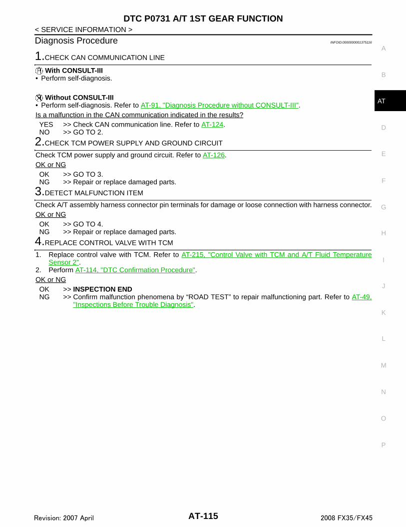
DTC P0731 A/T 1ST GEAR FUNCTION
D
E
F
G
H
I
J
K
L
M
A
B
T
N
O
P
< SERVICE INFORMATION >
A
Diagnosis Procedure INFOID:0000000001375116
1.CHECK CAN COMMUNICATION LINE
With CONSULT-III• Perform self-diagnosis.
Without CONSULT-III• Perform self-diagnosis. Refer to AT-91, "Diagnosis Procedure without CONSULT-III".Is a malfunction in the CAN communication indicated in the results?YES >> Check CAN communication line. Refer to AT-124.NO >> GO TO 2.
2.CHECK TCM POWER SUPPLY AND GROUND CIRCUIT
Check TCM power supply and ground circuit. Refer to AT-126.OK or NGOK >> GO TO 3.NG >> Repair or replace damaged parts.
3.DETECT MALFUNCTION ITEM
Check A/T assembly harness connector pin terminals for damage or loose connection with harness connector.OK or NGOK >> GO TO 4.NG >> Repair or replace damaged parts.
4.REPLACE CONTROL VALVE WITH TCM
1. Replace control valve with TCM. Refer to AT-215, "Control Valve with TCM and A/T Fluid TemperatureSensor 2".
2. Perform AT-114, "DTC Confirmation Procedure".OK or NGOK >> INSPECTION ENDNG >> Confirm malfunction phenomena by “ROAD TEST” to repair malfunctioning part. Refer to AT-49,
"Inspections Before Trouble Diagnosis".
AT-115Revision: 2007 April 2008 FX35/FX45

DTC P0732 A/T 2ND GEAR FUNCTION
< SERVICE INFORMATION >DTC P0732 A/T 2ND GEAR FUNCTION
Description INFOID:0000000001375117
This malfunction is detected when the A/T does not shift into 2nd gear position as instructed by TCM. This isnot only caused by electrical malfunction (circuits open or shorted) but also by mechanical malfunction suchas control valve sticking, improper solenoid valve operation.
On Board Diagnosis Logic INFOID:0000000001375118
Diagnostic trouble code “P0732 A/T 2ND GR FNCTN” with CONSULT-III or 19th judgment flicker withoutCONSULT-III is detected when TCM detects any inconsistency in the actual gear ratio.
Possible Cause INFOID:0000000001375119
• Harness or connectors (Solenoid circuits are open or shorted.)
• Input clutch solenoid valve• Front brake solenoid valve• Direct clutch solenoid valve• High and low reverse clutch solenoid valve• Each clutch• Hydraulic control circuit
DTC Confirmation Procedure INFOID:0000000001375120
CAUTION:Always drive vehicle at a safe speed.NOTE:If “DTC Confirmation Procedure” has been previously performed, always turn ignition switch OFF andwait at least 10 seconds before performing the next test.After the repair, perform the following procedure to confirm the malfunction is eliminated.
WITH CONSULT-III1. Start the engine and select “DATA MONITOR” mode for “TRANSMISSION” with CONSULT-III.2. Make sure that “ATF TEMP 1” is within the following range.
ATF TEMP 1: 20°C – 140°CIf out of range, drive vehicle to warm ATF or stop engine to cool ATF.
3. Select “2ND GR FNCTN P0732” of “DTC WORK SUPPORT” mode for “TRANSMISSION” with CON-SULT-III.
4. Drive vehicle and maintain the following conditions.VEHICLE SPEED: 10 km/h (6 MPH) or moreACCELE POSI: 0.6/8 or moreENGINE SPEED: TURBINE REV − 50 rpm or moreTURBINE REV: 300 rpm or moreGEAR: “2” positionMANU MODE SW: ON
5. Keep the current driving status for at least 5 consecutive seconds if CONSULT-III screen changes from“OUT OF CONDITION” to “TESTING”.CAUTION:If “TESTING” does not appear on CONSULT-III for a long time, select “SELF-DIAG RESULTS”. Incase a 1st trip DTC other than P0732 is shown, refer to “AT-84, "CONSULT-III Function (TRANSMIS-SION)"”.If “COMPLETED RESULT NG” is detected, go to AT-117, "Diagnosis Procedure".If “STOP VEHICLE” is detected, go to the following step.
6. Stop vehicle.7. Drive vehicle in “D” position allowing it to shift from 1st to 5th gear and check shift timing and shift shock.- Touch “OK” to complete the inspection when normally shifted from the 1st to 5th gear.- Touch “NG” when an unusual shift shock, etc. occurs in spite of shifting from the 1st to 5th gear. Go to AT-
49, "Inspections Before Trouble Diagnosis".- Perform AT-84, "CONSULT-III Function (TRANSMISSION)" when not shifted from the 1st to 5th gear.
(Neither “OK” nor “NG” are indicated.)
AT-116Revision: 2007 April 2008 FX35/FX45

DTC P0732 A/T 2ND GEAR FUNCTION
D
E
F
G
H
I
J
K
L
M
A
B
T
N
O
P
< SERVICE INFORMATION >
A
Diagnosis Procedure INFOID:0000000001375121
1.CHECK CAN COMMUNICATION LINE
With CONSULT-III• Perform self-diagnosis.
Without CONSULT-III• Perform self-diagnosis. Refer to AT-91, "Diagnosis Procedure without CONSULT-III".Is a malfunction in the CAN communication indicated in the results?YES >> Check CAN communication line. Refer to AT-94.NO >> GO TO 2.
2.CHECK TCM POWER SUPPLY AND GROUND CIRCUIT
Check TCM power supply and ground circuit. Refer to AT-160.OK or NGOK >> GO TO 3.NG >> Repair or replace damaged parts.
3.DETECT MALFUNCTION ITEM
Check A/T assembly harness connector pin terminals for damage or loose connection with harness connector.OK or NGOK >> GO TO 4.NG >> Repair or replace damaged parts.
4.REPLACE CONTROL VALVE WITH TCM
1. Replace control valve with TCM. Refer to AT-215, "Control Valve with TCM and A/T Fluid TemperatureSensor 2".
2. Perform AT-116, "DTC Confirmation Procedure".OK or NGOK >> INSPECTION ENDNG >> Confirm malfunction phenomena by “ROAD TEST” to repair malfunctioning part. Refer to AT-49,
"Inspections Before Trouble Diagnosis".
AT-117Revision: 2007 April 2008 FX35/FX45

DTC P0733 A/T 3RD GEAR FUNCTION
< SERVICE INFORMATION >DTC P0733 A/T 3RD GEAR FUNCTION
Description INFOID:0000000001375122
This malfunction is detected when the A/T does not shift into 3rd gear position as instructed by TCM. This isnot only caused by electrical malfunction (circuits open or shorted) but also by mechanical malfunction suchas control valve sticking, improper solenoid valve operation.
On Board Diagnosis Logic INFOID:0000000001375123
Diagnostic trouble code “P0733 A/T 3RD GR FNCTN” with CONSULT-III or 20th judgment flicker withoutCONSULT-III is detected when TCM detects any inconsistency in the actual gear ratio.
Possible Cause INFOID:0000000001375124
• Harness or connectors (Solenoid circuits are open or shorted.)
• Input clutch solenoid valve• Front brake solenoid valve• Direct clutch solenoid valve• High and low reverse clutch solenoid valve• Each clutch• Hydraulic control circuit
DTC Confirmation Procedure INFOID:0000000001375125
CAUTION:Always drive vehicle at a safe speed.NOTE:If “DTC Confirmation Procedure” has been previously performed, always turn ignition switch OFF andwait at least 10 seconds before performing the next test.After the repair, perform the following procedure to confirm the malfunction is eliminated.
WITH CONSULT-III1. Start the engine and select “DATA MONITOR” mode for “TRANSMISSION” with CONSULT-III.2. Make sure that “ATF TEMP 1” is within the following range.
ATF TEMP 1: 20°C – 140°CIf out of range, drive vehicle to warm ATF or stop engine to cool ATF.
3. Select “3RD GR FNCTN P0733” of “DTC WORK SUPPORT” mode for “TRANSMISSION” with CON-SULT-III.
4. Drive vehicle and maintain the following conditions.VEHICLE SPEED: 10 km/h (6 MPH) or moreACCELE POSI: 0.6/8 or moreENGINE SPEED: TURBINE REV − 50 rpm or moreTURBINE REV: 300 rpm or moreGEAR: “3” positionMANU MODE SW: ON
5. Keep the current driving status for at least 5 consecutive seconds if CONSULT-III screen changes from“OUT OF CONDITION” to “TESTING”.CAUTION:If “TESTING” does not appear on CONSULT-III for a long time, select “SELF-DIAG RESULTS”. Incase a 1st trip DTC other than P0732 is shown, refer to “AT-84, "CONSULT-III Function (TRANSMIS-SION)"”.If “COMPLETED RESULT NG” is detected, go to AT-119, "Diagnosis Procedure".If “STOP VEHICLE” is detected, go to the following step.
6. Stop vehicle.7. Drive vehicle in “D” position allowing it to shift from 1st to 5th gear and check shift timing and shift shock.- Touch “OK” to complete the inspection when normally shifted from the 1st to 5th gear.- Touch “NG” when an unusual shift shock, etc. occurs in spite of shifting from the 1st to 5th gear. Go to AT-
49, "Inspections Before Trouble Diagnosis".- Perform AT-84, "CONSULT-III Function (TRANSMISSION)" when not shifted from the 1st to 5th gear.
(Neither “OK” nor “NG” are indicated.)
AT-118Revision: 2007 April 2008 FX35/FX45

DTC P0733 A/T 3RD GEAR FUNCTION
D
E
F
G
H
I
J
K
L
M
A
B
T
N
O
P
< SERVICE INFORMATION >
A
Diagnosis Procedure INFOID:0000000001375126
1.CHECK CAN COMMUNICATION LINE
With CONSULT-III• Perform self-diagnosis.
Without CONSULT-III• Perform self-diagnosis. Refer to AT-91, "Diagnosis Procedure without CONSULT-III".Is a malfunction in the CAN communication indicated in the results?YES >> Check CAN communication line. Refer to AT-94.NO >> GO TO 2.
2.CHECK TCM POWER SUPPLY AND GROUND CIRCUIT
Check TCM power supply and ground circuit. Refer to AT-160.OK or NGOK >> GO TO 3.NG >> Repair or replace damaged parts.
3.DETECT MALFUNCTION ITEM
Check A/T assembly harness connector pin terminals for damage or loose connection with harness connector.OK or NGOK >> GO TO 4.NG >> Repair or replace damaged parts.
4.REPLACE CONTROL VALVE WITH TCM
1. Replace control valve with TCM. Refer to AT-215, "Control Valve with TCM and A/T Fluid TemperatureSensor 2".
2. Perform AT-119, "Diagnosis Procedure".OK or NGOK >> INSPECTION ENDNG >> Confirm malfunction phenomena by “ROAD TEST” to repair malfunctioning part. Refer to AT-49,
"Inspections Before Trouble Diagnosis".
AT-119Revision: 2007 April 2008 FX35/FX45

DTC P0734 A/T 4TH GEAR FUNCTION
< SERVICE INFORMATION >DTC P0734 A/T 4TH GEAR FUNCTION
Description INFOID:0000000001375127
This malfunction is detected when the A/T does not shift into 4th gear position as instructed by TCM. This isnot only caused by electrical malfunction (circuits open or shorted) but also by mechanical malfunction suchas control valve sticking, improper solenoid valve operation.
On Board Diagnosis Logic INFOID:0000000001375128
Diagnostic trouble code “P0734 A/T 4TH GR FNCTN” with CONSULT-III or 21st judgment flicker without CON-SULT-III is detected when TCM detects any inconsistency in the actual gear ratio.
Possible Cause INFOID:0000000001375129
• Harness or connectors (Solenoid circuits are open or shorted.)
• Input clutch solenoid valve• Front brake solenoid valve• Direct clutch solenoid valve• High and low reverse clutch solenoid valve• Each clutch• Hydraulic control circuit
DTC Confirmation Procedure INFOID:0000000001375130
CAUTION:Always drive vehicle at a safe speed.NOTE:If “DTC Confirmation Procedure” has been previously performed, always turn ignition switch OFF andwait at least 10 seconds before performing the next test.After the repair, perform the following procedure to confirm the malfunction is eliminated.
WITH CONSULT-III1. Start the engine and select “DATA MONITOR” mode for “TRANSMISSION” with CONSULT-III.2. Make sure that “ATF TEMP 1” is within the following range.
ATF TEMP 1: 20°C – 140°CIf out of range, drive vehicle to warm ATF or stop engine to cool ATF.
3. Select “4TH GR FNCTN P0734” of “DTC WORK SUPPORT” mode for “TRANSMISSION” with CON-SULT-III.
4. Drive vehicle and maintain the following conditions.VEHICLE SPEED: 10 km/h (6 MPH) or moreACCELE POSI: 0.6/8 or moreENGINE SPEED: TURBINE REV − 50 rpm or moreTURBINE REV: 300 rpm or moreGEAR: “4” positionMANU MODE SW: ON
5. Keep the current driving status for at least 5 consecutive seconds if CONSULT-III screen changes from“OUT OF CONDITION” to “TESTING”.CAUTION:If “TESTING” does not appear on CONSULT-III for a long time, select “SELF-DIAG RESULTS”. Incase a 1st trip DTC other than P0734 is shown, refer to “AT-84, "CONSULT-III Function (TRANSMIS-SION)"”.If “COMPLETED RESULT NG” is detected, go to AT-121, "Diagnosis Procedure".If “STOP VEHICLE” is detected, go to the following step.
6. Stop vehicle.7. Drive vehicle in “D” position allowing it to shift from 1st to 5th gear and check shift timing and shift shock.- Touch “OK” to complete the inspection when normally shifted from the 1st to 5th gear.- Touch “NG” when an unusual shift shock, etc. occurs in spite of shifting from the 1st to 5th gear. Go to AT-
49, "Inspections Before Trouble Diagnosis".- Perform AT-84, "CONSULT-III Function (TRANSMISSION)" when not shifted from the 1st to 5th gear.
(Neither “OK” nor “NG” are indicated.)
AT-120Revision: 2007 April 2008 FX35/FX45

DTC P0734 A/T 4TH GEAR FUNCTION
D
E
F
G
H
I
J
K
L
M
A
B
T
N
O
P
< SERVICE INFORMATION >
A
Diagnosis Procedure INFOID:0000000001375131
1.CHECK CAN COMMUNICATION LINE
With CONSULT-III• Perform self-diagnosis.
Without CONSULT-III• Perform self-diagnosis. Refer to AT-91, "Diagnosis Procedure without CONSULT-III".Is a malfunction in the CAN communication indicated in the results?YES >> Check CAN communication line. Refer to AT-94.NO >> GO TO 2.
2.CHECK TCM POWER SUPPLY AND GROUND CIRCUIT
Check TCM power supply and ground circuit. Refer to AT-160.OK or NGOK >> GO TO 3.NG >> Repair or replace damaged parts.
3.DETECT MALFUNCTION ITEM
Check A/T assembly harness connector pin terminals for damage or loose connection with harness connector.OK or NGOK >> GO TO 4.NG >> Repair or replace damaged parts.
4.REPLACE CONTROL VALVE WITH TCM
1. Replace control valve with TCM. Refer to AT-215, "Control Valve with TCM and A/T Fluid TemperatureSensor 2".
2. Perform AT-120, "DTC Confirmation Procedure".OK or NGOK >> INSPECTION ENDNG >> Confirm malfunction phenomena by “ROAD TEST” to repair malfunctioning part. Refer to AT-49,
"Inspections Before Trouble Diagnosis".
AT-121Revision: 2007 April 2008 FX35/FX45

DTC P0735 A/T 5TH GEAR FUNCTION
< SERVICE INFORMATION >DTC P0735 A/T 5TH GEAR FUNCTION
Description INFOID:0000000001375132
This malfunction is detected when the A/T does not shift into 5th gear position as instructed by TCM. This isnot only caused by electrical malfunction (circuits open or shorted) but also by mechanical malfunction suchas control valve sticking, improper solenoid valve operation.
On Board Diagnosis Logic INFOID:0000000001375133
Diagnostic trouble code “P0735 A/T 5TH GR FNCTN” with CONSULT-III or 22nd judgment flicker withoutCONSULT-III is detected when TCM detects any inconsistency in the actual gear ratio.
Possible Cause INFOID:0000000001375134
• Harness or connectors (Solenoid circuits are open or shorted.)
• Input clutch solenoid valve• Front brake solenoid valve• Direct clutch solenoid valve• High and low reverse clutch solenoid valve• Each clutch• Hydraulic control circuit
DTC Confirmation Procedure INFOID:0000000001375135
CAUTION:Always drive vehicle at a safe speed.NOTE:If “DTC Confirmation Procedure” has been previously performed, always turn ignition switch OFF andwait at least 10 seconds before performing the next test.After the repair, perform the following procedure to confirm the malfunction is eliminated.
WITH CONSULT-III1. Start the engine and select “DATA MONITOR” mode for “TRANSMISSION” with CONSULT-III.2. Make sure that “ATF TEMP 1” is within the following range.
ATF TEMP 1: 20°C – 140°CIf out of range, drive vehicle to warm ATF or stop engine to cool ATF.
3. Select “5TH GR FNCTN P0735” of “DTC WORK SUPPORT” mode for “TRANSMISSION” with CON-SULT-III.
4. Drive vehicle and maintain the following conditions.VEHICLE SPEED: 10 km/h (6 MPH) or moreACCELE POSI: 0.6/8 or moreENGINE SPEED: TURBINE REV − 50 rpm or moreTURBINE REV: 300 rpm or moreGEAR: “5” positionMANU MODE SW: ON
5. Keep the current driving status for at least 5 consecutive seconds if CONSULT-III screen changes from“OUT OF CONDITION” to “TESTING”.CAUTION:If “TESTING” does not appear on CONSULT-III for a long time, select “SELF-DIAG RESULTS”. Incase a 1st trip DTC other than P0735 is shown, refer to “AT-84, "CONSULT-III Function (TRANSMIS-SION)"”.If “COMPLETED RESULT NG” is detected, go to AT-123, "Diagnosis Procedure".If “STOP VEHICLE” is detected, go to the following step.
6. Stop vehicle.7. Drive vehicle in “D” position allowing it to shift from 1st to 5th gear and check shift timing and shift shock.- Touch “OK” to complete the inspection when normally shifted from the 1st to 5th gear.- Touch “NG” when an unusual shift shock, etc. occurs in spite of shifting from the 1st to 5th gear. Go to AT-
49, "Inspections Before Trouble Diagnosis".- Perform AT-84, "CONSULT-III Function (TRANSMISSION)" when not shifted from the 1st to 5th gear.
(Neither “OK” nor “NG” are indicated.)
AT-122Revision: 2007 April 2008 FX35/FX45

DTC P0735 A/T 5TH GEAR FUNCTION
D
E
F
G
H
I
J
K
L
M
A
B
T
N
O
P
< SERVICE INFORMATION >
A
Diagnosis Procedure INFOID:0000000001375136
1.CHECK CAN COMMUNICATION LINE
With CONSULT-III• Perform self-diagnosis.
Without CONSULT-III• Perform self-diagnosis. Refer to AT-91, "Diagnosis Procedure without CONSULT-III".Is a malfunction in the CAN communication indicated in the results?YES >> Check CAN communication line. Refer to AT-94.NO >> GO TO 2.
2.CHECK TCM POWER SUPPLY AND GROUND CIRCUIT
Check TCM power supply and ground circuit. Refer to AT-160.OK or NGOK >> GO TO 3.NG >> Repair or replace damaged parts.
3.DETECT MALFUNCTION ITEM
Check A/T assembly harness connector pin terminals for damage or loose connection with harness connector.OK or NGOK >> GO TO 4.NG >> Repair or replace damaged parts.
4.REPLACE CONTROL VALVE WITH TCM
1. Replace control valve with TCM. Refer to AT-215, "Control Valve with TCM and A/T Fluid TemperatureSensor 2".
2. Perform AT-122, "DTC Confirmation Procedure".OK or NGOK >> INSPECTION ENDNG >> Confirm malfunction phenomena by “ROAD TEST” to repair malfunctioning part. Refer to AT-49,
"Inspections Before Trouble Diagnosis".
AT-123Revision: 2007 April 2008 FX35/FX45

DTC P0740 TORQUE CONVERTER CLUTCH SOLENOID VALVE
< SERVICE INFORMATION >DTC P0740 TORQUE CONVERTER CLUTCH SOLENOID VALVE
Description INFOID:0000000001327209
• The torque converter clutch solenoid valve is activated, with the gear in D5, M3, M4 and M5 by the TCM inresponse to signals sent from the vehicle speed sensor and accelerator pedal position sensor (throttle posi-tion sensor). Torque converter clutch piston operation will then be controlled.
• Lock-up operation, however, is prohibited when A/T fluid temperature is too low.• When the accelerator pedal is depressed (less than 1.0/8) in lock-up condition, the engine speed should not
change abruptly. If there is a big jump in engine speed, there is no lock-up.
CONSULT-III Reference Value in Data Monitor Mode INFOID:0000000001327210
On Board Diagnosis Logic INFOID:0000000001327211
Diagnostic trouble code “P0740 TCC SOLENOID/CIRC” with CONSULT-III or 3rd judgement flicker withoutCONSULT-III is detected under the following conditions.• When TCM detects an improper voltage drop when it tries to operate the solenoid valve.• When TCM detects as irregular by comparing target value with monitor value.
Possible Cause INFOID:0000000001327212
• Torque converter clutch solenoid valve• Harness or connectors
(Solenoid circuit is open or shorted.)
DTC Confirmation Procedure INFOID:0000000001327213
CAUTION:Always drive vehicle at a safe speed.NOTE:If “DTC Confirmation Procedure” has been previously performed, always turn ignition switch “OFF”and wait at least 10 seconds before performing the next test.After the repair, perform the following procedure to confirm the malfunction is eliminated.
WITH CONSULT-III1. Turn ignition switch ON.2. Select “SELECTION FROM MENU” in “DATA MONITOR” mode for “TRANSMISSION” with CONSULT-III
and check monitor “VHCL/S SE-A/T”, “ACCELE POSI” and “SLCT LVR POSI”.3. Touch “START”.4. Start engine and maintain the following conditions for at least 5 consecutive seconds.
VHCL/S SE-A/T: 80 km/h (50 MPH) or moreACCELE POSI: 0.5/8 - 1.0/8SLCT LVR POSI: “D” position Driving location: Driving the vehicle uphill (increased engine load) will help maintain the drivingconditions required for this test.
5. If DTC is detected go to AT-124, "Diagnosis Procedure".
WITH GSTFollow the procedure “WITH CONSULT-III”.
Diagnosis Procedure INFOID:0000000001327214
1.CHECK INPUT SIGNAL
With CONSULT-III1. Turn ignition switch ON.
Item name Condition Display value (Approx.)
TCC SOLENOIDSlip lock-up is active 0.2 - 0.4 A
Lock-up is active 0.4 - 0.6 A
AT-124Revision: 2007 April 2008 FX35/FX45

DTC P0740 TORQUE CONVERTER CLUTCH SOLENOID VALVE
D
E
F
G
H
I
J
K
L
M
A
B
T
N
O
P
< SERVICE INFORMATION >
A
2. Select “MAIN SIGNALS” in “DATA MONITOR” mode for “TRANSMISSION” with CONSULT-III.3. Start engine.4. Read out the value of “TCC SOLENOID” while driving.
OK or NGOK >> GO TO 4.NG >> GO TO 2.
2.CHECK TCM POWER SUPPLY AND GROUND CIRCUIT
Check TCM power supply and ground circuit. Refer to AT-160.OK or NGOK >> GO TO 3.NG >> Repair or replace damaged parts.
3.DETECT MALFUNCTIONING ITEM
Check A/T assembly harness connector pin terminals for damage or loose connection with harness connector.OK or NGOK >> Replace the control valve with TCM. Refer to AT-215, "Control Valve with TCM and A/T Fluid Tem-
perature Sensor 2".NG >> Repair or replace damaged parts.
4.CHECK DTC
Perform AT-124, "DTC Confirmation Procedure".OK or NGOK >> INSPECTION ENDNG >> GO TO 2.
Item name Condition Display value (Approx.)
TCC SOLENOIDSlip lock-up is active 0.2 - 0.4 A
Lock-up is active 0.4 - 0.6 A
AT-125Revision: 2007 April 2008 FX35/FX45

DTC P0744 A/T TCC S/V FUNCTION (LOCK-UP)
< SERVICE INFORMATION >DTC P0744 A/T TCC S/V FUNCTION (LOCK-UP)
Description INFOID:0000000001327215
This malfunction is detected when the A/T does not shift into 5th gear position or the torque converter clutchdoes not lock-up as instructed by the TCM. This is not only caused by electrical malfunction (circuits open orshorted) but also by mechanical malfunction such as control valve sticking, improper solenoid valve operation,etc.
CONSULT-III Reference Value in Data Monitor Mode INFOID:0000000001327216
On Board Diagnosis Logic INFOID:0000000001327217
Diagnostic trouble code “P0744 A/T TCC S/V FNCTN” with CONSULT-III or 3rd judgement flicker withoutCONSULT-III is detected under the following conditions.• When A/T cannot perform lock-up even if electrical circuit is good.• When TCM detects as irregular by comparing difference value with slip rotation.
Possible Cause INFOID:0000000001327218
• Harness or connectors(Solenoid circuit is open or shorted.)
• Torque converter clutch solenoid valve• Hydraulic control circuit
DTC Confirmation Procedure INFOID:0000000001327219
CAUTION:Always drive vehicle at a safe speed.NOTE:If “DTC Confirmation Procedure” has been previously performed, always turn ignition switch OFF andwait at least 10 seconds before performing the next test.After the repair, perform the following procedure to confirm the malfunction is eliminated.
WITH CONSULT-III1. Start engine.2. Select “DATA MONITOR” mode for “TRANSMISSION” with CONSULT-III.3. Drive vehicle and maintain the following conditions for at least 30 consecutive seconds.
ACCELE POSI: More than 1.0/8SLCT LVR POSI: “D” position TCC SOLENOID: 0.4 - 0.6 AVEHICLE SPEED: 80 km/h (50 MPH) or moreDriving location: Driving the vehicle uphill (increased engine load) will help maintain the drivingconditions required for this test.
4. If DTC is detected, go to AT-126, "Diagnosis Procedure".
WITH GSTFollow the procedure “WITH CONSULT-III”.
Diagnosis Procedure INFOID:0000000001327220
1.CHECK INPUT SIGNAL
With CONSULT-III1. Turn ignition switch ON.2. Select “MAIN SIGNALS” in “DATA MONITOR” mode for “TRANSMISSION” with CONSULT-III.3. Start the engine.
Item name Condition Display value (Approx.)
TCC SOLENOIDSlip lock-up is active 0.2 - 0.4 A
Lock-up is active 0.4 - 0.6 A
AT-126Revision: 2007 April 2008 FX35/FX45

DTC P0744 A/T TCC S/V FUNCTION (LOCK-UP)
D
E
F
G
H
I
J
K
L
M
A
B
T
N
O
P
< SERVICE INFORMATION >
A
4. Read out the value of “TCC SOLENOID” while driving.
OK or NGOK >> GO TO 4.NG >> GO TO 2.
2.CHECK TCM POWER SUPPLY AND GROUND CIRCUIT
Check TCM power supply and ground circuit. Refer to AT-160.OK or NGOK >> GO TO 3.NG >> Repair or replace damaged parts.
3.DETECT MALFUNCTIONING ITEM
Check A/T assembly harness connector pin terminals for damage or loose connection with harness connector.OK or NGOK >> Replace the control valve with TCM. Refer to AT-215, "Control Valve with TCM and A/T Fluid Tem-
perature Sensor 2".NG >> Repair or replace damaged parts.
4.CHECK DTC
Perform AT-126, "DTC Confirmation Procedure".OK or NGOK >> INSPECTION ENDNG >> GO TO 2.
Item name Condition Display value (Approx.)
TCC SOLENOIDSlip lock-up is active 0.2 - 0.4 A
Lock-up is active 0.4 - 0.6 A
AT-127Revision: 2007 April 2008 FX35/FX45
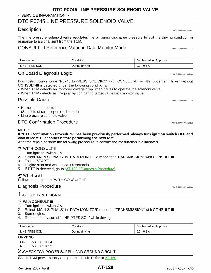
DTC P0745 LINE PRESSURE SOLENOID VALVE
< SERVICE INFORMATION >DTC P0745 LINE PRESSURE SOLENOID VALVE
Description INFOID:0000000001327221
The line pressure solenoid valve regulates the oil pump discharge pressure to suit the driving condition inresponse to a signal sent from the TCM.
CONSULT-III Reference Value in Data Monitor Mode INFOID:0000000001327222
On Board Diagnosis Logic INFOID:0000000001327223
Diagnostic trouble code “P0745 L/PRESS SOL/CIRC” with CONSULT-III or 4th judgement flicker withoutCONSULT-III is detected under the following conditions.• When TCM detects an improper voltage drop when it tries to operate the solenoid valve.• When TCM detects as irregular by comparing target value with monitor value.
Possible Cause INFOID:0000000001327224
• Harness or connectors(Solenoid circuit is open or shorted.)
• Line pressure solenoid valve
DTC Confirmation Procedure INFOID:0000000001327225
NOTE:If “DTC Confirmation Procedure” has been previously performed, always turn ignition switch OFF andwait at least 10 seconds before performing the next test.After the repair, perform the following procedure to confirm the malfunction is eliminated.
WITH CONSULT-III1. Turn ignition switch ON. 2. Select “MAIN SIGNALS” in “DATA MONITOR” mode for “TRANSMISSION” with CONSULT-III.3. Touch “START”.4. Engine start and wait at least 5 seconds.5. If DTC is detected, go to “AT-128, "Diagnosis Procedure".
WITH GSTFollow the procedure “WITH CONSULT-III”.
Diagnosis Procedure INFOID:0000000001327226
1.CHECK INPUT SIGNAL
With CONSULT-III1. Turn ignition switch ON.2. Select “MAIN SIGNALS” in “DATA MONITOR” mode for “TRANSMISSION” with CONSULT-III.3. Start engine.4. Read out the value of “LINE PRES SOL” while driving.
OK or NGOK >> GO TO 4.NG >> GO TO 2.
2.CHECK TCM POWER SUPPLY AND GROUND CIRCUIT
Check TCM power supply and ground circuit. Refer to AT-160.
Item name Condition Display value (Approx.)
LINE PRES SOL During driving 0.2 - 0.6 A
Item name Condition Display value (Approx.)
LINE PRES SOL During driving 0.2 - 0.6 A
AT-128Revision: 2007 April 2008 FX35/FX45

DTC P0745 LINE PRESSURE SOLENOID VALVE
D
E
F
G
H
I
J
K
L
M
A
B
T
N
O
P
< SERVICE INFORMATION >
A
OK or NGOK >> GO TO 3.NG >> Repair or replace damaged parts.
3.DETECT MALFUNCTIONING ITEM
Check A/T assembly harness connector pin terminals for damage or loose connection with harness connectorOK or NGOK >> Replace the control valve with TCM. Refer to AT-215, "Control Valve with TCM and A/T Fluid Tem-
perature Sensor 2".NG >> Repair or replace damaged parts.
4.CHECK DTC
Perform AT-128, "DTC Confirmation Procedure".OK or NGOK >> INSPECTION ENDNG >> GO TO 2.
AT-129Revision: 2007 April 2008 FX35/FX45

DTC P1705 THROTTLE POSITION SENSOR
< SERVICE INFORMATION >DTC P1705 THROTTLE POSITION SENSOR
Description INFOID:0000000001327227
Electric throttle control actuator consists of throttle control motor, accelerator pedal position sensor, throttleposition sensor, etc. The actuator sends a signal to the ECM, and ECM sends signals to TCM with CAN com-munication.
CONSULT-III Reference Value in Data Monitor Mode INFOID:0000000001327228
On Board Diagnosis Logic INFOID:0000000001327229
Diagnostic trouble code “P1705 TP SEN/CIRC A/T” with CONSULT-III or 15th judgement flicker without CON-SULT-III is detected when TCM does not receive the proper accelerator pedal position signals (input by CANcommunication) from ECM.
Possible Cause INFOID:0000000001327230
Harness or connectors(Sensor circuit is open or shorted.)
DTC Confirmation Procedure INFOID:0000000001327231
NOTE:If “DTC Confirmation Procedure” has been previously performed, always turn ignition switch OFF andwait at least 10 seconds before performing the next test.After the repair, perform the following procedure to confirm the malfunction is eliminated.
WITH CONSULT-III1. Turn ignition switch ON. 2. Select “ECU INPUT SIGNALS” in “DATA MONITOR” mode for “TRANSMISSION” with CONSULT-III.3. Touch “START”.4. Start engine and let it idle for 1 second.5. If DTC is detected, go to AT-130, "Diagnosis Procedure".
Diagnosis Procedure INFOID:0000000001327232
1.CHECK CAN COMMUNICATION LINE
With CONSULT-III• Perform the self-diagnosis.
Without CONSULT-III• Perform the self-diagnosis. Refer to AT-91, "Diagnosis Procedure without CONSULT-III".Is a malfunction in the CAN communication indicated in the results?YES >> Check CAN communication line. Refer to AT-94.NO >> GO TO 2.
2.CHECK DTC WITH TCM
With CONSULT-III1. Turn ignition switch ON.2. Select “ECU INPUT SIGNALS” in “DATA MONITOR” mode for “TRANSMISSION” with CONSULT-III.3. Depress accelerator pedal and read out the value of “ACCELE POSI”.
Item name Condition Display value (Approx.)
ACCELE POSIReleased accelerator pedal. 0.0/8
Fully depressed accelerator pedal. 8.0/8
AT-130Revision: 2007 April 2008 FX35/FX45

DTC P1705 THROTTLE POSITION SENSOR
D
E
F
G
H
I
J
K
L
M
A
B
T
N
O
P
< SERVICE INFORMATION >
A
4. Select “SELF-DIAG RESULTS” mode for “TRANSMISSION” with CONSULT-III. Refer to AT-84, "CON-SULT-III Function (TRANSMISSION)".
OK or NGOK >> GO TO 4.NG >> GO TO 3.
3.CHECK DTC WITH ECM
With CONSULT-III1. Turn ignition switch ON.2. Select “SELF-DIAG RESULTS” mode for “ENGINE” with CONSULT-III. Refer to EC-117, "CONSULT-III
Function (ENGINE)" (for VQ35DE) or EC-695, "CONSULT-III Function (ENGINE)" (for VK45DE).OK or NGOK >> GO TO 4.NG >> Check the DTC detected item. Refer to EC-117, "CONSULT-III Function (ENGINE)" (for
VQ35DE) or EC-695, "CONSULT-III Function (ENGINE)" (for VK45DE).• If CAN communication line is detected, go to AT-94.
4.CHECK DTC
Perform AT-130, "DTC Confirmation Procedure".OK or NGOK >> INSPECTION ENDNG >> GO TO 5.
5.CHECK TCM POWER SUPPLY AND GROUND CIRCUIT
Check TCM power supply and ground circuit. Refer to AT-160.OK or NGOK >> GO TO 6.NG >> Repair or replace damaged parts.
6.DETECT MALFUNCTIONING ITEM
Check A/T assembly harness connector pin terminals for damage or loose connection with harness connector.OK or NGOK >> Replace the control valve with TCM. Refer to AT-215, "Control Valve with TCM and A/T Fluid Tem-
perature Sensor 2".NG >> Repair or replace damaged parts.
Item name Condition Display value (Approx.)
ACCELE POSIReleased accelerator pedal. 0.0/8
Fully depressed accelerator pedal. 8.0/8
AT-131Revision: 2007 April 2008 FX35/FX45

DTC P1710 A/T FLUID TEMPERATURE SENSOR CIRCUIT
< SERVICE INFORMATION >DTC P1710 A/T FLUID TEMPERATURE SENSOR CIRCUIT
Description INFOID:0000000001327233
The A/T fluid temperature sensor detects the A/T fluid temperature and sends a signal to the TCM.
CONSULT-III Reference Value in Data Monitor Mode INFOID:0000000001327234
On Board Diagnosis Logic INFOID:0000000001327235
Diagnostic trouble code “P1710 (A/T), P0710 (ENGINE) ATF TEMP SEN/CIRC” with CONSULT-III or 10thjudgement flicker without CONSULT-III is detected when TCM receives an excessively low or high voltagefrom the sensor.
Possible Cause INFOID:0000000001327236
• Harness or connectors(Sensor circuit is open or shorted.)
• A/T fluid temperature sensors 1 and/or 2
DTC Confirmation Procedure INFOID:0000000001327237
CAUTION:Always drive vehicle at a safe speed.NOTE:If “DTC Confirmation Procedure” has been previously performed, always turn ignition switch OFF andwait at least 10 seconds before performing the next test.After the repair, perform the following procedure to confirm the malfunction is eliminated.
WITH CONSULT-III1. Turn ignition switch ON.2. Select “SELECTION FROM MENU” in “DATA MONITOR” mode for “TRANSMISSION” with CONSULT-III
and check monitor “VHCL/S SE-A/T”, “ACCELE POSI” and “SLCT LVR POSI”.3. Touch “START”.4. Start engine and maintain the following conditions for at least 10 minutes (Total). (It is not necessary to
maintain continuously.)VHCL/S SE-A/T: 10 km/h (6 MPH) or moreACCELE POSI: More than 1.0/8SLCT LVR POSI: “D” position
5. If DTC is detected, go to AT-133, "Diagnosis Procedure".
WITH GSTFollow the procedure “WITH CONSULT-III”.
Item name Condition °C (°F) Display value (Approx.)
ATF TEMP SE 10 (32) - 20 (68) - 80 (176)
3.3 - 2.7 - 0.9 V
ATF TEMP SE 2 3.3 - 2.5 - 0.7 V
AT-132Revision: 2007 April 2008 FX35/FX45

DTC P1710 A/T FLUID TEMPERATURE SENSOR CIRCUIT
D
E
F
G
H
I
J
K
L
M
A
B
T
N
O
P
< SERVICE INFORMATION >
A
Wiring Diagram - AT - FTS INFOID:0000000001327238
Diagnosis Procedure INFOID:0000000001327239
1.CHECK A/T FLUID TEMPERATURE SENSOR 1 SIGNAL
With CONSULT-III1. Start engine.
TCWM0251E
AT-133Revision: 2007 April 2008 FX35/FX45

DTC P1710 A/T FLUID TEMPERATURE SENSOR CIRCUIT
< SERVICE INFORMATION >2. Select “ECU INPUT SIGNALS” in “DATA MONITOR” mode for “TRANSMISSION” with CONSULT-III.3. Read out the value of “ATF TEMP SE 1”.OK or NGOK >> GO TO 2.NG >> GO TO 3.
2.CHECK A/T FLUID TEMPERATURE SENSOR 2 SIGNAL
With CONSULT-III1. Start engine.2. Select “ECU INPUT SIGNALS” in “DATA MONITOR” mode for “TRANSMISSION” with CONSULT-III.3. Read out the value of “ATF TEMP SE 2”.
OK or NGOK >> GO TO 8.NG >> GO TO 5.
3.CHECK A/T FLUID TEMPERATURE SENSOR 1
Check A/T fluid temperature sensor 1. Refer to AT-135, "Component Inspection".OK or NGOK >> GO TO 4.NG >> Replace the control valve with TCM. Refer to AT-215, "Control Valve with TCM and A/T Fluid Tem-
perature Sensor 2".
4.CHECK SUB-HARNESS
1. Disconnect park/neutral position switch connector and TCM connector.2. Check continuity between park/neutral position switch connector
terminals and TCM connector terminals.
3. If OK, check harness for short to ground and short to power.OK or NGOK >> GO TO 7.NG >> Replace open circuit or short to ground and short to power in harness or connectors.
5.CHECK A/T FLUID TEMPERATURE SENSOR 2
Check A/T fluid temperature sensor 2. Refer to AT-135, "Component Inspection".OK or NGOK >> GO TO 6.NG >> Replace the A/T fluid temperature sensor 2. Refer to AT-215, "Control Valve with TCM and A/T
Fluid Temperature Sensor 2".
6.CHECK TERMINAL CORD ASSEMBLY
1. Disconnect A/T fluid temperature sensor 2 connector and TCM connector.
Item name Condition °C (°F) Display value (Approx.)
ATF TEMP SE 1 0 (32) - 20 (68) - 80 (176) 3.3 - 2.7 - 0.9 V
Item name Condition °C (°F) Display value (Approx.)
ATF TEMP SE 2 0 (32) - 20 (68) - 80 (176) 3.3 - 2.5 - 0.7 V
Item Connector Terminal Continuity
Park/neutral position switch connector
F505 6Yes
TCM connector F503 19
Park/neutral position switch connector
F505 7Yes
TCM connector F503 18 SCIA5461E
AT-134Revision: 2007 April 2008 FX35/FX45

DTC P1710 A/T FLUID TEMPERATURE SENSOR CIRCUIT
D
E
F
G
H
I
J
K
L
M
A
B
T
N
O
P
< SERVICE INFORMATION >
A
2. Check continuity between A/T fluid temperature sensor 2 con-nector terminals and TCM connector terminals.
3. If OK, check harness for short to ground and short to power.OK or NGOK >> GO TO 7.NG >> Replace open circuit or short to ground and short to power in harness or connectors.
7.CHECK TCM POWER SUPPLY AND GROUND CIRCUIT
1. Check TCM power supply and ground circuit. Refer to AT-160.2. Reinstall any part removed.OK or NGOK >> Replace the control valve with TCM. Refer to AT-215, "Control Valve with TCM and A/T Fluid Tem-
perature Sensor 2".NG >> Repair or replace damaged parts.
8.CHECK DTC
Perform AT-132, "DTC Confirmation Procedure".OK or NGOK >> INSPECTION ENDNG >> GO TO 1.
Component Inspection INFOID:0000000001327240
A/T FLUID TEMPERATURE SENSOR 11. Remove control valve with TCM. Refer to AT-215, "Control Valve with TCM and A/T Fluid Temperature
Sensor 2".2. Check resistance between terminals.
3. If NG, replace the control valve with TCM. Refer to AT-215,"Control Valve with TCM and A/T Fluid Temperature Sensor 2".
A/T FLUID TEMPERATURE SENSOR 21. Remove A/T fluid temperature sensor 2. Refer to AT-215, "Control Valve with TCM and A/T Fluid Temper-
ature Sensor 2".
Item Connector Terminal Continuity
A/T fluid temperature sen-sor 2 connector
F507 1Yes
TCM connector F502 3
A/T fluid temperature sen-sor 2 connector
F507 2Yes
TCM connector F502 5 SCIA5462E
Name Connector TerminalTemperature
°C (°F)Resistance (Ap-
prox.)
A/T fluid temperature sensor 1
F505 6 - 7
0 (32) 15 kΩ
20 (68) 6.5 kΩ
80 (176) 0.9 kΩ
SCIA5463E
AT-135Revision: 2007 April 2008 FX35/FX45

DTC P1710 A/T FLUID TEMPERATURE SENSOR CIRCUIT
< SERVICE INFORMATION >2. Check resistance between terminals.3. If NG, replace the A/T fluid temperature sensor 2. Refer to AT-215, "Control Valve with TCM and A/T Fluid Temperature Sen-sor 2".
Name Connector TerminalTemperature
°C (°F)Resistance (Ap-
prox.)
A/T fluid temperature sensor 2
F507 1 - 2
0 (32) 10 kΩ
20 (68) 4 kΩ
80 (176) 0.5 kΩ
SCIA5271E
AT-136Revision: 2007 April 2008 FX35/FX45

DTC P1721 VEHICLE SPEED SENSOR MTR
D
E
F
G
H
I
J
K
L
M
A
B
T
N
O
P
< SERVICE INFORMATION >
A
DTC P1721 VEHICLE SPEED SENSOR MTR
Description INFOID:0000000001327241
The vehicle speed sensor-MTR signal is transmitted from unified meter and A/C amp. to TCM by CAN com-munication line. The signal functions as an auxiliary device to the revolution sensor when it is malfunctioning.The TCM will then use the vehicle speed sensor·MTR signal.
CONSULT-III Reference Value in Data Monitor Mode INFOID:0000000001327242
On Board Diagnosis Logic INFOID:0000000001327243
Diagnostic trouble code “P1721 VEH SPD SE/CIR-MTR” with CONSULT-III is detected when TCM does notreceive the proper vehicle speed sensor MTR signal (input by CAN communication) from combination meter.
Possible Cause INFOID:0000000001327244
Harness or connectors(Sensor circuit is open or shorted.)
DTC Confirmation Procedure INFOID:0000000001327245
CAUTION:Always drive vehicle at a safe speed.NOTE:If “DTC Confirmation Procedure” has been previously performed, always turn ignition switch OFF andwait at least 10 seconds before performing the next test.After the repair, perform the following procedure to confirm the malfunction is eliminated.
WITH CONSULT-III1. Turn ignition switch ON.2. Select “ECU INPUT SIGNALS” in “DATA MONITOR” mode for “TRANSMISSION” with CONSULT-III.3. Touch “START”.4. Start engine and maintain the following conditions for at least 5 consecutive seconds.
ACCELE POSI: 1.0/8 or lessVHCL/S SE-MTR: 30 km/h (17 MPH) or more
5. If DTC is detected, go to AT-137, "Diagnosis Procedure".
Diagnosis Procedure INFOID:0000000001327246
1.CHECK CAN COMMUNICATION LINE
With CONSULT-III• Perform the self-diagnosis.
Without CONSULT-III• Perform the self-diagnosis. Refer to AT-91, "Diagnosis Procedure without CONSULT-III".Is malfunction in the CAN communication indicated in the result?YES >> Check CAN communication line. Refer to AT-94.NO >> GO TO 2.
2.CHECK INPUT SIGNAL
With CONSULT-III1. Start engine.2. Select “ECU INPUT SIGNALS” in “DATA MONITOR” mode for “TRANSMISSION” with CONSULT-III.3. Drive vehicle and read out the value of “VHCL/S SE-MTR”.
Item name Condition Display value
VHCL/S SE-MTR During driving Approximately matches the speedometer reading.
AT-137Revision: 2007 April 2008 FX35/FX45

DTC P1721 VEHICLE SPEED SENSOR MTR
< SERVICE INFORMATION >OK or NGOK >> GO TO 4.NG >> GO TO 3.
3.CHECK COMBINATION METERS
Check combination meters. Refer to DI-15, "Trouble Diagnosis".OK or NGOK >> GO TO 4.NG >> Repair or replace damaged parts.
4.CHECK DTC
Perform AT-137, "DTC Confirmation Procedure".OK or NGOK >> INSPECTION ENDNG >> GO TO 5.
5.CHECK TCM POWER SUPPLY AND GROUND CIRCUIT
Check TCM power supply and ground circuit. Refer to AT-160.OK or NGOK >> GO TO 6.NG >> Repair or replace damaged parts.
6.DETECT MALFUNCTIONING ITEM
Check A/T assembly harness connector pin terminals for damage or loose connection with harness connector.OK or NGOK >> Replace the control valve with TCM. Refer to AT-215, "Control Valve with TCM and A/T Fluid Tem-
perature Sensor 2".NG >> Repair or replace damaged parts.
Item name Condition Display value
VHCL/S SE-MTR During driving Approximately matches the speedometer reading.
AT-138Revision: 2007 April 2008 FX35/FX45

DTC P1730 A/T INTERLOCK
D
E
F
G
H
I
J
K
L
M
A
B
T
N
O
P
< SERVICE INFORMATION >
A
DTC P1730 A/T INTERLOCK
Description INFOID:0000000001327247
Fail-safe function to detect interlock conditions.
On Board Diagnosis Logic INFOID:0000000001327248
Diagnostic trouble code “P1730 A/T INTERLOCK” with CONSULT-III or 12th judgement flicker without CON-SULT-III is detected when TCM does not receive the proper voltage signal from the sensor and switch.TCM monitors and compares gear position and conditions of each ATF pressure switch when gear is steady.
Possible Cause INFOID:0000000001327249
• Harness or connectors(Solenoid and switch circuit is open or shorted.)
• Low coast brake solenoid valve• ATF pressure switch 2
DTC Confirmation Procedure INFOID:0000000001327250
NOTE:If “DTC Confirmation Procedure” has been previously performed, always turn ignition switch OFF andwait at least 10 seconds before performing the next test.After the repair, perform the following procedure to confirm the malfunction is eliminated.
WITH CONSULT-III1. Turn ignition switch ON.2. Select “MAIN SIGNALS” in “DATA MONITOR” mode for “TRANSMISSION” with CONSULT-III.3. Touch “START”.4. Start engine.5. Drive vehicle and maintain the following conditions for at least 2 consecutive seconds.
SLCT LVR POSI: “D” position 6. If DTC is detected, go to AT-139, "Diagnosis Procedure".
WITH GSTFollow the procedure “WITH CONSULT-III”.
Judgement of A/T Interlock INFOID:0000000001327251
• When A/T Interlock is judged to be malfunctioning, the vehicle should be fixed in 2nd gear, and should be setin a condition in which it can travel.When one of the following fastening patterns is detected, the fail-safe function in correspondence with theindividual pattern should be performed.
NOTE:When the vehicle is driven fixed in 2nd gear, a turbine revolution sensor malfunction is displayed, butthis is not a turbine revolution sensor malfunction.• When interlock is detected at the 3rd gear or more, it is locked at the 2nd gear.
Diagnosis Procedure INFOID:0000000001327252
1.SELF-DIAGNOSIS
With CONSULT-III1. Drive vehicle.2. Stop vehicle and turn ignition switch OFF.3. Turn ignition switch ON.4. Select “SELF-DIAG RESULTS” mode for “TRANSMISSION” with CONSULT-III.
Without CONSULT-III1. Drive vehicle.2. Stop vehicle and turn ignition switch OFF.3. Turn ignition switch ON.
AT-139Revision: 2007 April 2008 FX35/FX45

DTC P1730 A/T INTERLOCK
< SERVICE INFORMATION >4. Perform self-diagnosis. Refer to AT-91, "Diagnosis Procedure without CONSULT-III". OK or NGOK >> GO TO 2.NG >> Check low coast brake solenoid valve circuit and function. Refer to AT-151, AT-153.2.CHECK DTC
Perform AT-139, "DTC Confirmation Procedure".OK or NGOK >> INSPECTION ENDNG >> GO TO 3.
3.CHECK TCM POWER SUPPLY AND GROUND CIRCUIT
Check TCM power supply and ground circuit. Refer to AT-160.OK or NGOK >> GO TO 4.NG >> Repair or replace damaged parts.
4.DETECT MALFUNCTIONING ITEM
Check A/T assembly harness connector pin terminals for damage or loose connection with harness connector.OK or NGOK >> Replace the control valve with TCM. Refer to AT-215, "Control Valve with TCM and A/T Fluid Tem-
perature Sensor 2".NG >> Repair or replace damaged parts.
AT-140Revision: 2007 April 2008 FX35/FX45

DTC P1731 A/T 1ST ENGINE BRAKING
D
E
F
G
H
I
J
K
L
M
A
B
T
N
O
P
< SERVICE INFORMATION >
A
DTC P1731 A/T 1ST ENGINE BRAKING
Description INFOID:0000000001327253
Fail-safe function to prevent sudden decrease in speed by engine brake other than at M1 position.
CONSULT-III Reference Value in Data Monitor Mode INFOID:0000000001327254
On Board Diagnosis Logic INFOID:0000000001327255
Diagnostic trouble code “P1731 A/T 1ST E/BRAKING” with CONSULT-III or 13th judgement flicker withoutCONSULT-III is detected under the following conditions.• When TCM does not receive the proper voltage signal from the sensor.• When TCM monitors each ATF pressure switch and solenoid monitor value, and detects as irregular when
engine brake of 1st gear acts other than at M1 position.
Possible Cause INFOID:0000000001327256
• Harness or connectors(Sensor circuit is open or shorted.)
• Low coast brake solenoid valve• ATF pressure switch 2
DTC Confirmation Procedure INFOID:0000000001327257
CAUTION:• Always drive vehicle at a safe speed.• Be careful not to rev engine into red zone on the tachometer.NOTE:If “DTC Confirmation Procedure” has been previously preformed, always turn ignition switch OFF andwait at least 10 seconds before performing the next test.After the repair, perform the following procedure to confirm the malfunction is eliminated.
WITH CONSULT-III1. Turn ignition switch ON.2. Select “SELECTION FROM MENU” in “DATA MONITOR” mode for “TRANSMISSION” with CONSULT-III
and check monitor “ENGINE SPEED”, “MANU MODE SW” and “GEAR”.3. Touch “START”.4. Start engine.5. Drive vehicle and maintain the following conditions for at least 2 consecutive seconds.
ENGINE SPEED: 1,200 rpmMANU MODE SW: ONGEAR: “1” position
6. If DTC is detected, go to AT-141, "Diagnosis Procedure".
Diagnosis Procedure INFOID:0000000001327258
1.CHECK INPUT SIGNALS
With CONSULT-III1. Start the engine.2. Select “SELECTION FROM MENU” in “DATA MONITOR” mode for “TRANSMISSION” with CONSULT-III.3. Drive vehicle in the “M” position (1st gear), and confirm the ON/OFF actuation of “ATF PRES SW 2” and
“ON OFF SOL”.
Item name Condition Display value
ON OFF SOLLow coast brake engaged. Refer to AT-18. ON
Low coast brake disengaged. Refer to AT-18. OFF
ATF PRES SW 2Low coast brake engaged. Refer to AT-18. ON
Low coast brake disengaged. Refer to AT-18. OFF
AT-141Revision: 2007 April 2008 FX35/FX45

DTC P1731 A/T 1ST ENGINE BRAKING
< SERVICE INFORMATION >OK or NGOK >> GO TO 4.NG >> GO TO 2.
2.CHECK TCM POWER SUPPLY AND GROUND CIRCUIT
Check TCM power supply and ground circuit. Refer to AT-160.OK or NGOK >> GO TO 3.NG >> Repair or replace damaged parts.
3.DETECT MALFUNCTIONING ITEM
Check A/T assembly harness connector pin terminals for damage or loose connection with harness connector.OK or NGOK >> Replace the control valve with TCM. Refer to AT-215, "Control Valve with TCM and A/T Fluid Tem-
perature Sensor 2".NG >> Repair or replace damaged parts.
4.CHECK DTC
Perform AT-141, "DTC Confirmation Procedure".OK or NGOK >> INSPECTION ENDNG >> GO TO 2.
Item name Condition Display value
ON OFF SOLLow coast brake engaged. Refer to AT-18. ON
Low coast brake disengaged. Refer to AT-18. OFF
ATF PRES SW 2Low coast brake engaged. Refer to AT-18. ON
Low coast brake disengaged. Refer to AT-18. OFF
AT-142Revision: 2007 April 2008 FX35/FX45

DTC P1752 INPUT CLUTCH SOLENOID VALVE
D
E
F
G
H
I
J
K
L
M
A
B
T
N
O
P
< SERVICE INFORMATION >
A
DTC P1752 INPUT CLUTCH SOLENOID VALVE
Description INFOID:0000000001327259
Input clutch solenoid valve is controlled by the TCM in response to signals sent from the PNP switch, vehiclespeed sensor and accelerator pedal position sensor (throttle position sensor). Gears will then be shifted to theoptimum position.
CONSULT-III Reference Value in Data Monitor Mode INFOID:0000000001327260
On Board Diagnosis Logic INFOID:0000000001327261
Diagnostic trouble code “P1752 I/C SOLENOID/CIRC” with CONSULT-III or 5th judgement flicker withoutCONSULT-III is detected under the following conditions.• When TCM detects an improper voltage drop when it tries to operate the solenoid valve.• When TCM detects as irregular by comparing target value with monitor value.
Possible Cause INFOID:0000000001327262
• Harness or connectors(Solenoid circuit is open or shorted.)
• Input clutch solenoid valve
DTC Confirmation Procedure INFOID:0000000001327263
CAUTION:Always drive vehicle at a safe speed.NOTE:If “DTC Confirmation Procedure” has been previously performed, always turn ignition switch OFF andwait at least 10 seconds before performing the next test.After the repair, perform the following procedure to confirm the malfunction is eliminated.
WITH CONSULT-III1. Turn ignition switch ON.2. Select “SELECTION FROM MENU” in “DATA MONITOR” mode for “TRANSMISSION” with CONSULT-III
and check monitor “ACCELE POSI”, “SLCT LVR POSI” and “GEAR”.3. Touch “START”.4. Start engine.5. Drive vehicle and maintain the following conditions for at least 5 consecutive seconds.
ACCELE POSI: 1.5/8 - 2.0/8SLCT LVR POSI: “D” position GEAR: “3” ⇒ “4” (I/C ON/OFF)Driving location: Driving the vehicle uphill (increased engine load) will help maintain the drivingconditions required for this test.
6. If DTC is detected go to AT-143, "Diagnosis Procedure".
WITH GSTFollow the procedure “WITH CONSULT-III”.
Diagnosis Procedure INFOID:0000000001327264
1.CHECK INPUT SIGNAL
With CONSULT-III1. Turn ignition switch ON.2. Select “MAIN SIGNALS” in “DATA MONITOR” mode for “TRANSMISSION” with CONSULT-III.3. Start the engine.
Item name Condition Display value (Approx.)
I/C SOLENOIDInput clutch disengaged. Refer to AT-18. 0.6 - 0.8 A
Input clutch engaged. Refer to AT-18. 0 - 0.05 A
AT-143Revision: 2007 April 2008 FX35/FX45

DTC P1752 INPUT CLUTCH SOLENOID VALVE
< SERVICE INFORMATION >4. Read out the value of “I/C SOLENOID” while driving.OK or NGOK >> GO TO 4.NG >> GO TO 2.
2.CHECK TCM POWER SUPPLY AND GROUND CIRCUIT
Check TCM power supply and ground circuit. Refer to AT-160.OK or NGOK >> GO TO 3.NG >> Repair or replace damaged parts.
3.DETECT MALFUNCTIONING ITEM
Check A/T assembly harness connector pin terminals for damage or loose connection with harness connector.OK or NGOK >> Replace the control valve with TCM. Refer to AT-215, "Control Valve with TCM and A/T Fluid Tem-
perature Sensor 2".NG >> Repair or replace damaged parts.
4.CHECK DTC
Perform AT-147, "DTC Confirmation Procedure".OK or NGOK >> INSPECTION ENDNG >> GO TO 2.
Item name Condition Display value(Approx.)
I/C SOLENOIDInput clutch disengaged. Refer to AT-18. 0.6 - 0.8 A
Input clutch engaged. Refer to AT-18. 0 - 0.05 A
AT-144Revision: 2007 April 2008 FX35/FX45
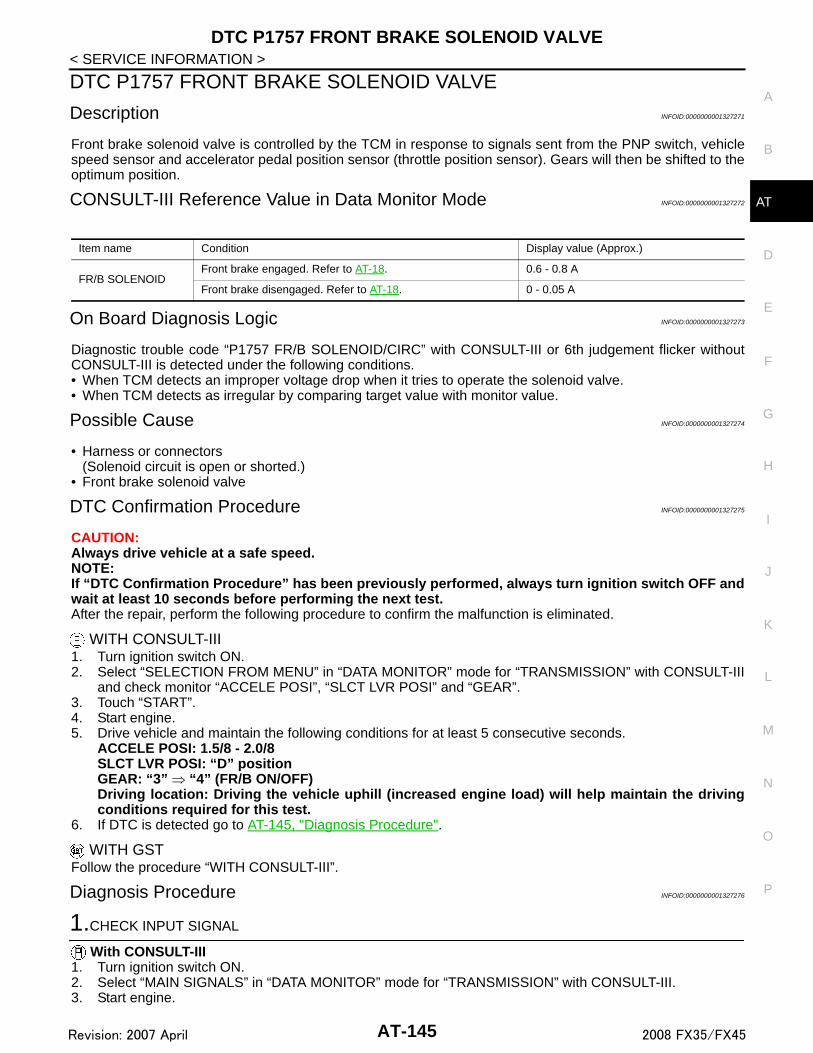
DTC P1757 FRONT BRAKE SOLENOID VALVE
D
E
F
G
H
I
J
K
L
M
A
B
T
N
O
P
< SERVICE INFORMATION >
A
DTC P1757 FRONT BRAKE SOLENOID VALVE
Description INFOID:0000000001327271
Front brake solenoid valve is controlled by the TCM in response to signals sent from the PNP switch, vehiclespeed sensor and accelerator pedal position sensor (throttle position sensor). Gears will then be shifted to theoptimum position.
CONSULT-III Reference Value in Data Monitor Mode INFOID:0000000001327272
On Board Diagnosis Logic INFOID:0000000001327273
Diagnostic trouble code “P1757 FR/B SOLENOID/CIRC” with CONSULT-III or 6th judgement flicker withoutCONSULT-III is detected under the following conditions.• When TCM detects an improper voltage drop when it tries to operate the solenoid valve.• When TCM detects as irregular by comparing target value with monitor value.
Possible Cause INFOID:0000000001327274
• Harness or connectors(Solenoid circuit is open or shorted.)
• Front brake solenoid valve
DTC Confirmation Procedure INFOID:0000000001327275
CAUTION:Always drive vehicle at a safe speed.NOTE:If “DTC Confirmation Procedure” has been previously performed, always turn ignition switch OFF andwait at least 10 seconds before performing the next test.After the repair, perform the following procedure to confirm the malfunction is eliminated.
WITH CONSULT-III1. Turn ignition switch ON.2. Select “SELECTION FROM MENU” in “DATA MONITOR” mode for “TRANSMISSION” with CONSULT-III
and check monitor “ACCELE POSI”, “SLCT LVR POSI” and “GEAR”.3. Touch “START”.4. Start engine.5. Drive vehicle and maintain the following conditions for at least 5 consecutive seconds.
ACCELE POSI: 1.5/8 - 2.0/8SLCT LVR POSI: “D” position GEAR: “3” ⇒ “4” (FR/B ON/OFF)Driving location: Driving the vehicle uphill (increased engine load) will help maintain the drivingconditions required for this test.
6. If DTC is detected go to AT-145, "Diagnosis Procedure".
WITH GSTFollow the procedure “WITH CONSULT-III”.
Diagnosis Procedure INFOID:0000000001327276
1.CHECK INPUT SIGNAL
With CONSULT-III1. Turn ignition switch ON.2. Select “MAIN SIGNALS” in “DATA MONITOR” mode for “TRANSMISSION” with CONSULT-III.3. Start engine.
Item name Condition Display value (Approx.)
FR/B SOLENOIDFront brake engaged. Refer to AT-18. 0.6 - 0.8 A
Front brake disengaged. Refer to AT-18. 0 - 0.05 A
AT-145Revision: 2007 April 2008 FX35/FX45

DTC P1757 FRONT BRAKE SOLENOID VALVE
< SERVICE INFORMATION >4. Read out the value of “FR/B SOLENOID” while driving.OK or NGOK >> GO TO 4.NG >> GO TO 2.
2.CHECK TCM POWER SUPPLY AND GROUND CIRCUIT
Check TCM power supply and ground circuit. Refer to AT-160.OK or NGOK >> GO TO 3.NG >> Repair or replace damaged parts.
3.DETECT MALFUNCTIONING ITEM
Check A/T assembly harness connector pin terminals for damage or loose connection with harness connector.OK or NGOK >> Replace the control valve with TCM. Refer to AT-215, "Control Valve with TCM and A/T Fluid Tem-
perature Sensor 2".NG >> Repair or replace damaged parts.
4.CHECK DTC
Perform AT-106, "DTC Confirmation Procedure".OK or NGOK >> INSPECTION ENDNG >> GO TO 2.
Item name Condition Display value (Approx.)
FR/B SOLENOIDFront brake engaged. Refer to AT-18. 0.6 - 0.8 A
Front brake disengaged. Refer to AT-18. 0 - 0.05 A
AT-146Revision: 2007 April 2008 FX35/FX45

DTC P1762 DIRECT CLUTCH SOLENOID VALVE
D
E
F
G
H
I
J
K
L
M
A
B
T
N
O
P
< SERVICE INFORMATION >
A
DTC P1762 DIRECT CLUTCH SOLENOID VALVE
Description INFOID:0000000001327283
Direct clutch solenoid valve is controlled by the TCM in response to signals sent from the PNP switch, vehiclespeed sensor and accelerator pedal position sensor (throttle position sensor). Gears will then be shifted to theoptimum position.
CONSULT-III Reference Value in Data Monitor Mode INFOID:0000000001327284
On Board Diagnosis Logic INFOID:0000000001327285
Diagnostic trouble code “P1762 D/C SOLENOID/CIRC” with CONSULT-III or 2nd judgement flicker withoutCONSULT-III is detected under the following conditions.• When TCM detects an improper voltage drop when it tries to operate the solenoid valve.• When TCM detects as irregular by comparing target value with monitor value.
Possible Cause INFOID:0000000001327286
• Harness or connectors(Solenoid circuit is open or shorted.)
• Direct clutch solenoid valve
DTC Confirmation Procedure INFOID:0000000001327287
CAUTION:Always drive vehicle at a safe speed.NOTE:If “DTC Confirmation Procedure” has been previously performed, always turn ignition switch OFF andwait at least 10 seconds before performing the next test.After the repair, perform the following procedure to confirm the malfunction is eliminated.
WITH CONSULT-III1. Turn ignition switch ON.2. Select “SELECTION FROM MENU” in “DATA MONITOR” mode for “TRANSMISSION” with CONSULT-III
and check monitor “ACCELE POSI”, “SLCT LVR POSI” and “GEAR”.3. Touch “START”.4. Start engine.5. Drive vehicle and maintain the following conditions for at least 5 consecutive seconds.
ACCELE POSI: 1.5/8 - 2.0/8SLCT LVR POSI: “D” position GEAR: “1” ⇒ “2” (D/C ON/OFF)Driving location: Driving the vehicle uphill (increased engine load) will help maintain the drivingconditions required for this test.
6. If DTC is detected, go to AT-147, "Diagnosis Procedure".
WITH GSTFollow the procedure “WITH CONSULT-III”.
Diagnosis Procedure INFOID:0000000001327288
1.CHECK INPUT SIGNAL
With CONSULT-III1. Turn ignition switch ON.2. Select “MAIN SIGNALS” in “DATA MONITOR” mode for “TRANSMISSION” with CONSULT-III.3. Start the engine.
Item name Condition Display value (Approx.)
D/C SOLENOIDDirect clutch disengaged. Refer to AT-18. 0.6 - 0.8 A
Direct clutch engaged. Refer to AT-18. 0 - 0.05 A
AT-147Revision: 2007 April 2008 FX35/FX45

DTC P1762 DIRECT CLUTCH SOLENOID VALVE
< SERVICE INFORMATION >4. Read out the value of “D/C SOLENOID” while driving.OK or NGOK >> GO TO 4.NG >> GO TO 2.
2.CHECK TCM POWER SUPPLY AND GROUND CIRCUIT
Check TCM power supply and ground circuit. Refer to AT-160.OK or NGOK >> GO TO 3.NG >> Repair or replace damaged parts.
3.DETECT MALFUNCTIONING ITEM
Check A/T assembly harness connector pin terminals for damage or loose connection with harness connector.OK or NGOK >> Replace the control valve with TCM. Refer to AT-215, "Control Valve with TCM and A/T Fluid Tem-
perature Sensor 2".NG >> Repair or replace damaged parts.
4.CHECK DTC
Perform AT-147, "DTC Confirmation Procedure".OK or NGOK >> INSPECTION ENDNG >> GO TO 2.
Item name Condition Display value (Approx.)
D/C SOLENOIDDirect clutch disengaged. Refer to AT-18. 0.6 - 0.8 A
Direct clutch engaged. Refer to AT-18. 0 - 0.05 A
AT-148Revision: 2007 April 2008 FX35/FX45

DTC P1767 HIGH AND LOW REVERSE CLUTCH SOLENOID VALVE
D
E
F
G
H
I
J
K
L
M
A
B
T
N
O
P
< SERVICE INFORMATION >
A
DTC P1767 HIGH AND LOW REVERSE CLUTCH SOLENOID VALVE
Description INFOID:0000000001327295
High and low reverse clutch solenoid valve is controlled by the TCM in response to signals sent from the PNPswitch, vehicle speed sensor and accelerator pedal position sensor (throttle position sensor). Gears will thenbe shifted to the optimum position.
CONSULT-III Reference Value in Data Monitor Mode INFOID:0000000001327296
On Board Diagnosis Logic INFOID:0000000001327297
Diagnostic trouble code “P1767 HLR/C SOL/CIRC” with CONSULT-III or 8th judgement flicker without CON-SULT-III is detected under the following conditions.• When TCM detects an improper voltage drop when it tries to operate the solenoid valve.• When TCM detects as irregular by comparing target value with monitor value.
Possible Cause INFOID:0000000001327298
• Harness or connectors(Solenoid circuit is open or shorted.)
• High and low reverse clutch solenoid valve
DTC Confirmation Procedure INFOID:0000000001327299
CAUTION:Always drive vehicle at a safe speed.NOTE:If “DTC Confirmation Procedure” has been previously performed, always turn ignition switch OFF andwait at least 10 seconds before performing the next test.After the repair, perform the following procedure to confirm the malfunction is eliminated.
WITH CONSULT-III1. Turn ignition switch ON.2. Select “SELECTION FROM MENU” in “DATA MONITOR” mode for “TRANSMISSION” with CONSULT-III
and check monitor “ACCELE POSI”, “SLCT LVR POSI” and “GEAR”.3. Touch “START”.4. Start engine.5. Drive vehicle and maintain the following conditions for at least 5 consecutive seconds.
ACCELE POSI: 1.5/8 - 2.0/8SLCT LVR POSI: “D” position GEAR: “2” ⇒ “3” (HLR/C ON/OFF)Driving location: Driving the vehicle uphill (increased engine load) will help maintain the drivingconditions required for this test.
6. If DTC is detected, go to AT-149, "Diagnosis Procedure".
WITH GSTFollow the procedure “WITH CONSULT-III”.
Diagnosis Procedure INFOID:0000000001327300
1.CHECK INPUT SIGNAL
With CONSULT-III1. Turn ignition switch ON.2. Select “MAIN SIGNALS” in “DATA MONITOR” mode for “TRANSMISSION” with CONSULT-III.3. Start the engine.
Item name Condition Display value (Approx.)
HLR/C SOLHigh and low reverse clutch disengaged. Refer to AT-18. 0.6 - 0.8 A
High and low reverse clutch engaged. Refer to AT-18. 0 - 0.05 A
AT-149Revision: 2007 April 2008 FX35/FX45

DTC P1767 HIGH AND LOW REVERSE CLUTCH SOLENOID VALVE
< SERVICE INFORMATION >4. Read out the value of “HLR/C SOLENOID” while driving.OK or NGOK >> GO TO 4.NG >> GO TO 2.
2.CHECK TCM POWER SUPPLY AND GROUND CIRCUIT
Check TCM power supply and ground circuit. Refer to AT-160.OK or NGOK >> GO TO 3.NG >> Repair or replace damaged parts.
3.DETECT MALFUNCTIONING ITEM
Check A/T assembly harness connector pin terminals for damage or loose connection with harness connector.OK or NGOK >> Replace the control valve with TCM. Refer to AT-215, "Control Valve with TCM and A/T Fluid Tem-
perature Sensor 2".NG >> Repair or replace damaged parts.
4.CHECK DTC
Perform AT-149, "DTC Confirmation Procedure".OK or NGOK >> INSPECTION ENDNG >> GO TO 2.
Item name Condition Display value(Approx.)
HLR/C SOLHigh and low reverse clutch disengaged. Refer to AT-18. 0.6 - 0.8 A
High and low reverse clutch engaged. Refer to AT-18. 0 - 0.05 A
AT-150Revision: 2007 April 2008 FX35/FX45

DTC P1772 LOW COAST BRAKE SOLENOID VALVE
D
E
F
G
H
I
J
K
L
M
A
B
T
N
O
P
< SERVICE INFORMATION >
A
DTC P1772 LOW COAST BRAKE SOLENOID VALVE
Description INFOID:0000000001327307
Low coast brake solenoid valve is turned ON or OFF by the TCM in response to signals sent from the PNPswitch, vehicle speed sensor and accelerator pedal position sensor (throttle position sensor). Gears will thenbe shifted to the optimum position.
CONSULT-III Reference Value in Data Monitor Mode INFOID:0000000001327308
On Board Diagnosis Logic INFOID:0000000001327309
Diagnostic trouble code “P1772 LC/B SOLENOID/CIRC” with CONSULT-III or 7th judgement flicker withoutCONSULT-III is detected when TCM detects an improper voltage drop when it tries to operate the solenoidvalve.
Possible Cause INFOID:0000000001327310
• Harness or connectors(Solenoid circuit is open or shorted.)
• Low coast brake solenoid valve
DTC Confirmation Procedure INFOID:0000000001327311
NOTE:If “DTC Confirmation Procedure” has been previously performed, always turn ignition switch OFF andwait at least 10 seconds before performing the next test.After the repair, perform the following procedure to confirm the malfunction is eliminated.
WITH CONSULT-III1. Turn ignition switch ON.2. Select “SELECTION FROM MENU” in “DATA MONITOR” mode for “TRANSMISSION” with CONSULT-III
and check monitor “MANU MODE SW” and “GEAR”.3. Touch “START”.4. Start engine.5. Drive vehicle and maintain the following conditions for at least 5 consecutive seconds.
MANU MODE SW: ONGEAR: “1” or “2” (LC/B ON/OFF)
6. If DTC is detected, go to AT-151, "Diagnosis Procedure".
WITH GSTFollow the procedure “WITH CONSULT-III”.
Diagnosis Procedure INFOID:0000000001327312
1.CHECK INPUT SIGNAL
With CONSULT-III1. Turn ignition switch ON.2. Select “SELECTION FROM MENU” in “DATA MONITOR” mode for “TRANSMISSION” with CONSULT-III.3. Start engine.4. Read out the value of “ON OFF SOL” while driving.
Item name Condition Display value
ON OFF SOLLow coast brake engaged. Refer to AT-18. ON
Low coast brake disengaged. Refer to AT-18. OFF
Item name Condition Display value
ON OFF SOLLow coast brake engaged. Refer to AT-18. ON
Low coast brake disengaged. Refer to AT-18. OFF
AT-151Revision: 2007 April 2008 FX35/FX45

DTC P1772 LOW COAST BRAKE SOLENOID VALVE
< SERVICE INFORMATION >OK or NGOK >> GO TO 4.NG >> GO TO 2.2.CHECK TCM POWER SUPPLY AND GROUND CIRCUIT
Check TCM power supply and ground circuit. Refer to AT-160.OK or NGOK >> GO TO 3.NG >> Repair or replace damaged parts.
3.DETECT MALFUNCTIONING ITEM
Check A/T assembly harness connector pin terminals for damage or loose connection with harness connector.OK or NGOK >> Replace the control valve with TCM. Refer to AT-215, "Control Valve with TCM and A/T Fluid Tem-
perature Sensor 2".NG >> Repair or replace damaged parts.
4.CHECK DTC
Perform AT-151, "DTC Confirmation Procedure".OK or NGOK >> INSPECTION ENDNG >> GO TO 2.
AT-152Revision: 2007 April 2008 FX35/FX45
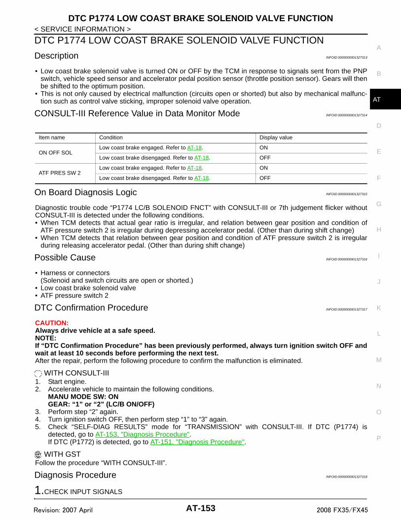
DTC P1774 LOW COAST BRAKE SOLENOID VALVE FUNCTION
D
E
F
G
H
I
J
K
L
M
A
B
T
N
O
P
< SERVICE INFORMATION >
A
DTC P1774 LOW COAST BRAKE SOLENOID VALVE FUNCTION
Description INFOID:0000000001327313
• Low coast brake solenoid valve is turned ON or OFF by the TCM in response to signals sent from the PNPswitch, vehicle speed sensor and accelerator pedal position sensor (throttle position sensor). Gears will thenbe shifted to the optimum position.
• This is not only caused by electrical malfunction (circuits open or shorted) but also by mechanical malfunc-tion such as control valve sticking, improper solenoid valve operation.
CONSULT-III Reference Value in Data Monitor Mode INFOID:0000000001327314
On Board Diagnosis Logic INFOID:0000000001327315
Diagnostic trouble code “P1774 LC/B SOLENOID FNCT” with CONSULT-III or 7th judgement flicker withoutCONSULT-III is detected under the following conditions.• When TCM detects that actual gear ratio is irregular, and relation between gear position and condition of
ATF pressure switch 2 is irregular during depressing accelerator pedal. (Other than during shift change)• When TCM detects that relation between gear position and condition of ATF pressure switch 2 is irregular
during releasing accelerator pedal. (Other than during shift change)
Possible Cause INFOID:0000000001327316
• Harness or connectors(Solenoid and switch circuits are open or shorted.)
• Low coast brake solenoid valve • ATF pressure switch 2
DTC Confirmation Procedure INFOID:0000000001327317
CAUTION:Always drive vehicle at a safe speed.NOTE:If “DTC Confirmation Procedure” has been previously performed, always turn ignition switch OFF andwait at least 10 seconds before performing the next test.After the repair, perform the following procedure to confirm the malfunction is eliminated.
WITH CONSULT-III1. Start engine.2. Accelerate vehicle to maintain the following conditions.
MANU MODE SW: ONGEAR: “1” or “2” (LC/B ON/OFF)
3. Perform step “2” again.4. Turn ignition switch OFF, then perform step “1” to “3” again.5. Check “SELF-DIAG RESULTS” mode for “TRANSMISSION” with CONSULT-III. If DTC (P1774) is
detected, go to AT-153, "Diagnosis Procedure".If DTC (P1772) is detected, go to AT-151, "Diagnosis Procedure".
WITH GSTFollow the procedure “WITH CONSULT-III”.
Diagnosis Procedure INFOID:0000000001327318
1.CHECK INPUT SIGNALS
Item name Condition Display value
ON OFF SOLLow coast brake engaged. Refer to AT-18. ON
Low coast brake disengaged. Refer to AT-18. OFF
ATF PRES SW 2Low coast brake engaged. Refer to AT-18. ON
Low coast brake disengaged. Refer to AT-18. OFF
AT-153Revision: 2007 April 2008 FX35/FX45

DTC P1774 LOW COAST BRAKE SOLENOID VALVE FUNCTION
< SERVICE INFORMATION >With CONSULT-III1. Start engine.2. Select “SELECTION FROM MENU” in “DATA MONITOR” mode for “TRANSMISSION” with CONSULT-III.3. Drive vehicle in the manual mode (1st or 2nd gear), and confirm the ON/OFF actuation of the “ATF PRES
SW 2” and “ON OFF SOL”.
OK or NGOK >> GO TO 4.NG >> GO TO 2.
2.CHECK TCM POWER SUPPLY AND GROUND CIRCUIT
Check TCM power supply and ground circuit. Refer to AT-160.OK or NGOK >> GO TO 3.NG >> Repair or replace damaged parts.
3.DETECT MALFUNCTIONING ITEM
Check A/T assembly harness connector pin terminals for damage or loose connection with harness connector.OK or NGOK >> Replace the control valve with TCM. Refer to AT-215, "Control Valve with TCM and A/T Fluid Tem-
perature Sensor 2".NG >> Repair or replace damaged parts.
4.CHECK DTC
Perform AT-153, "DTC Confirmation Procedure".OK or NGOK >> INSPECTION ENDNG >> GO TO 2.
Item name Condition Display value
ON OFF SOLLow coast brake engaged. Refer to AT-18. ON
Low coast brake disengaged. Refer to AT-18. OFF
ATF PRES SW 2Low coast brake engaged. Refer to AT-18. ON
Low coast brake disengaged. Refer to AT-18. OFF
AT-154Revision: 2007 April 2008 FX35/FX45

DTC P1815 MANUAL MODE SWITCH
D
E
F
G
H
I
J
K
L
M
A
B
T
N
O
P
< SERVICE INFORMATION >
A
DTC P1815 MANUAL MODE SWITCH
Description INFOID:0000000001327319
Manual mode switch is installed in A/T device. It sends manual mode switch, shift up and shift down switchsignals to TCM.TCM sends the switch signals to unified meter and A/C amp. by CAN communication line. Then manual modeswitch position is indicated on the A/T indicator. For inspection, refer to AT-166.
CONSULT-III Reference Value in Data Monitor Mode INFOID:0000000001327320
On Board Diagnosis Logic INFOID:0000000001327321
Diagnostic trouble code “P1815 MANU MODE SW/CIR” with CONSULT-IIII is detected when TCM monitorsManual mode, Non manual mode, Up or Down switch signal, and detects as irregular when impossible inputpattern occurs 1 second or more.
Possible Cause INFOID:0000000001327322
• Harness or connectors(These switches circuit is open or shorted.)
• Manual mode select switch (Into control device)• Manual mode position select switch (Into control device)
DTC Confirmation Procedure INFOID:0000000001327323
NOTE:If “DTC Confirmation Procedure” has been previously performed, always turn ignition switch OFF andwait at least 10 seconds before performing the next test.After the repair, perform the following procedure to confirm the malfunction is eliminated.
WITH CONSULT-III1. Turn ignition switch ON.2. Select “ECU INPUT SIGNALS” in “DATA MONITOR” mode for “TRANSMISSION” with CONSULT-III.3. Start engine.4. Drive vehicle and maintain the following conditions for at least 2 consecutive seconds.
MANU MODE SW: ON5. If DTC is detected, go to AT-158, "Diagnosis Procedure".
Item name Condition Display Value
MANU MODE SWManual shift gate position (neutral) ON
Other than the above OFF
NON M-MODE SWManual shift gate position OFF
Other than the above ON
UP SW LEVERselector lever: + side ON
Other than the above OFF
DOWN SW LEVERselector lever: - side ON
Other than the above OFF
AT-155Revision: 2007 April 2008 FX35/FX45

DTC P1815 MANUAL MODE SWITCH
< SERVICE INFORMATION >Wiring Diagram - AT - MMSW INFOID:0000000001327324
TCWM0498E
AT-156Revision: 2007 April 2008 FX35/FX45

DTC P1815 MANUAL MODE SWITCH
D
E
F
G
H
I
J
K
L
M
A
B
T
N
O
P
< SERVICE INFORMATION >
A
TCM terminals and data are reference value. Measured between each terminal and ground.TCWM0499E
TerminalWire color
Item Condition Data (Approx.)
3 L CAN-H – –
8 P CAN-L – –
AT-157Revision: 2007 April 2008 FX35/FX45

DTC P1815 MANUAL MODE SWITCH
< SERVICE INFORMATION >Diagnosis Procedure INFOID:0000000001327325
1.CHECK CAN COMMUNICATION LINE
Perform the self-diagnosis.Is a malfunction in the CAN communication indicated in the results?YES >> Check CAN communication line. Refer to AT-94.NO >> GO TO 2.
2.CHECK MANUAL MODE SWITCH CIRCUIT
With CONSULT-III1. Turn ignition switch ON.2. Select “ECU INPUT SIGNALS” in “DATA MONITOR” mode for “TRANSMISSION” with CONSULT-III.3. Read out ON/OFF switching action of “MANU MODE SW”, “NON M-MODE SW”, “UP SW LEVER”,
“DOWN SW LEVER”.
Without CONSULT-IIIDrive vehicle in the manual mode, and confirm that the actual gear position and the meter's indication of theposition mutually coincide when the selector lever is shifted to the “+ (up)” or “- (down)” side (1st ⇔ 5th gear).OK or NGOK >> GO TO 4.NG >> GO TO 3.
3.DETECT MALFUNCTIONING ITEM
Check the following.• Manual mode switch. Refer to AT-159, "Component Inspection".• Pin terminals for damage or loose connection with harness connector.• Open circuit or short to ground or short to power in harness or connector for A/T device (manual mode
switch).• Unified meter and A/C amp. Refer to DI-5.OK or NGOK >> GO TO 4.NG >> Repair or replace damaged parts.
4.CHECK DTC
Perform AT-155, "DTC Confirmation Procedure".OK or NGOK >> INSPECTION ENDNG >> GO TO 5.
9 GY Starter relaySelector lever in “N” and “P” positions. Battery voltage
Selector lever in other positions. 0 V
TerminalWire color
Item Condition Data (Approx.)
Item name Condition Display Value
MANU MODE SWManual shift gate position (neutral) ON
Other than the above OFF
NON M-MODE SWManual shift gate position OFF
Other than the above ON
UP SW LEVERselector lever: +side ON
Other than the above OFF
DOWN SW LEVERselector lever: -side ON
Other than the above OFF
AT-158Revision: 2007 April 2008 FX35/FX45

DTC P1815 MANUAL MODE SWITCH
D
E
F
G
H
I
J
K
L
M
A
B
T
N
O
P
< SERVICE INFORMATION >
A
5.CHECK TCM POWER SUPPLY AND GROUND CIRCUIT
Check TCM power supply and ground circuit. Refer to AT-160.OK or NGOK >> GO TO 6.NG >> Repair or replace damaged parts.
6.DETECT MALFUNCTIONING ITEM
Check A/T assembly harness connector pin terminals for damage or loose connection with harness connector.OK or NGOK >> Replace the control valve with TCM. Refer to AT-215, "Control Valve with TCM and A/T Fluid Tem-
perature Sensor 2".NG >> Repair or replace damaged parts.
Component Inspection INFOID:0000000001327326
MANUAL MODE SWITCHCheck continuity between terminals.
Item Position Connector Terminal Continuity
Manual mode select switch
Auto
M67
9 - 10
YesManual 6 - 9
Manual mode position select switch
UP 8 - 9
DOWN 7 - 9
SCIA2112E
AT-159Revision: 2007 April 2008 FX35/FX45

MAIN POWER SUPPLY AND GROUND CIRCUIT
< SERVICE INFORMATION >MAIN POWER SUPPLY AND GROUND CIRCUIT
Wiring Diagram - AT - MAIN INFOID:0000000001327351
TCWM0497E
AT-160Revision: 2007 April 2008 FX35/FX45
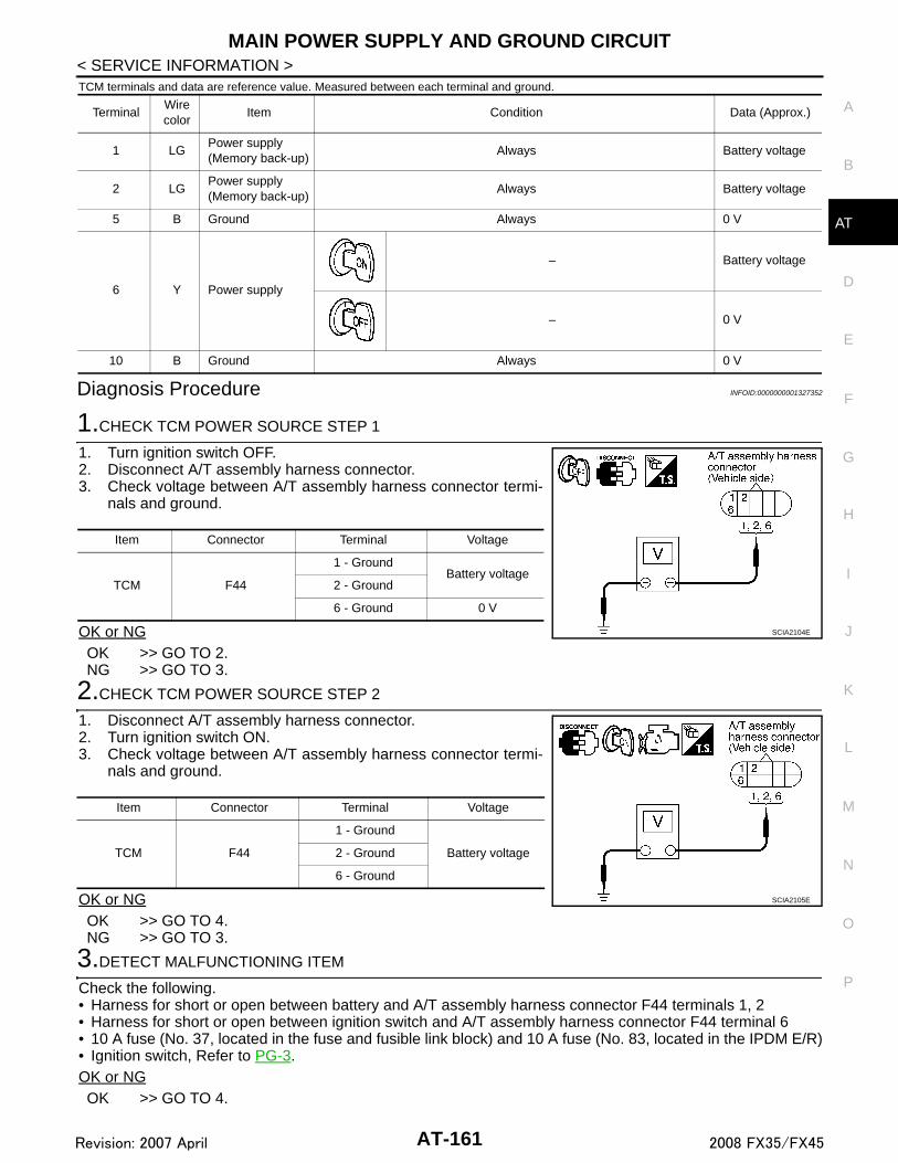
MAIN POWER SUPPLY AND GROUND CIRCUIT
D
E
F
G
H
I
J
K
L
M
A
B
T
N
O
P
< SERVICE INFORMATION >
A
TCM terminals and data are reference value. Measured between each terminal and ground.
Diagnosis Procedure INFOID:0000000001327352
1.CHECK TCM POWER SOURCE STEP 1
1. Turn ignition switch OFF.2. Disconnect A/T assembly harness connector.3. Check voltage between A/T assembly harness connector termi-
nals and ground.
OK or NGOK >> GO TO 2.NG >> GO TO 3.
2.CHECK TCM POWER SOURCE STEP 2
1. Disconnect A/T assembly harness connector.2. Turn ignition switch ON.3. Check voltage between A/T assembly harness connector termi-
nals and ground.
OK or NGOK >> GO TO 4.NG >> GO TO 3.
3.DETECT MALFUNCTIONING ITEM
Check the following.• Harness for short or open between battery and A/T assembly harness connector F44 terminals 1, 2• Harness for short or open between ignition switch and A/T assembly harness connector F44 terminal 6• 10 A fuse (No. 37, located in the fuse and fusible link block) and 10 A fuse (No. 83, located in the IPDM E/R)• Ignition switch, Refer to PG-3.OK or NGOK >> GO TO 4.
TerminalWire color
Item Condition Data (Approx.)
1 LGPower supply(Memory back-up)
Always Battery voltage
2 LGPower supply(Memory back-up)
Always Battery voltage
5 B Ground Always 0 V
6 Y Power supply
– Battery voltage
– 0 V
10 B Ground Always 0 V
Item Connector Terminal Voltage
TCM F44
1 - GroundBattery voltage
2 - Ground
6 - Ground 0 V
SCIA2104E
Item Connector Terminal Voltage
TCM F44
1 - Ground
Battery voltage2 - Ground
6 - Ground
SCIA2105E
AT-161Revision: 2007 April 2008 FX35/FX45
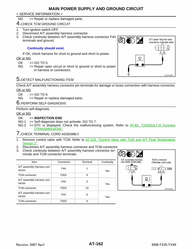
MAIN POWER SUPPLY AND GROUND CIRCUIT
< SERVICE INFORMATION >NG >> Repair or replace damaged parts.4.CHECK TCM GROUND CIRCUIT
1. Turn ignition switch OFF.2. Disconnect A/T assembly harness connector.3. Check continuity between A/T assembly harness connector F44
terminals and ground.
If OK, check harness for short to ground and short to power.OK or NGOK >> GO TO 5.NG >> Repair open circuit or short to ground or short to power
in harness or connectors.
5.DETECT MALFUNCTIONING ITEM
Check A/T assembly harness connector pin terminals for damage or loose connection with harness connector.OK or NGOK >> GO TO 6.NG >> Repair or replace damaged parts.
6.PERFORM SELF-DIAGNOSIS
Perform self-diagnosis.OK or NGOK >> INSPECTION ENDNG-1 >> Self-diagnosis does not activate: GO TO 7.NG-2 >> DTC is displayed: Check the malfunctioning system. Refer to AT-84, "CONSULT-III Function
(TRANSMISSION)".
7.CHECK TERMINAL CORD ASSEMBLY
1. Remove control valve with TCM. Refer to AT-215, "Control Valve with TCM and A/T Fluid TemperatureSensor 2".
2. Disconnect A/T assembly harness connector and TCM connector.3. Check continuity between A/T assembly harness connector ter-
minals and TCM connector terminals.
Continuity should exist.
SCIA2106E
Item Connector Terminal Continuity
A/T assembly harness con-nector
F44 1Yes
TCM connector F502 9
A/T assembly harness con-nector
F44 2Yes
TCM connector F502 10
A/T assembly harness con-nector
F44 6Yes
TCM connector F502 4
SCIA5464E
AT-162Revision: 2007 April 2008 FX35/FX45

MAIN POWER SUPPLY AND GROUND CIRCUIT
D
E
F
G
H
I
J
K
L
M
A
B
T
N
O
P
< SERVICE INFORMATION >
A
4. Check continuity between A/T assembly harness connector ter-minals and TCM connector terminals.
5. If OK, check harness for short to ground and short to power.OK or NGOK >> Replace the control valve with TCM. Refer to AT-215, "Control Valve with TCM and A/T Fluid Tem-
perature Sensor 2".NG >> Replace open circuit or short to ground and short to power in harness or connectors.
Item Connector Terminal Continuity
A/T assembly harness con-nector
F44 5Yes
TCM connector F504 21
A/T assembly harness con-nector
F44 10Yes
TCM connector F504 22 SCIA5465E
AT-163Revision: 2007 April 2008 FX35/FX45

CLOSED THROTTLE POSITION AND WIDE OPEN THROTTLE POSITION CIR-CUIT
< SERVICE INFORMATION >
CLOSED THROTTLE POSITION AND WIDE OPEN THROTTLE POSITIONCIRCUIT
CONSULT-III Reference Value in Data Monitor Mode INFOID:0000000001327353
Diagnosis Procedure INFOID:0000000001327354
1.CHECK CAN COMMUNICATION LINE
With CONSULT-III• Perform the self-diagnosis.
Without CONSULT-III• Perform the self-diagnosis. Refer to AT-91, "Diagnosis Procedure without CONSULT-III".Is a malfunction in the CAN communication indicated in the results?YES >> Check CAN communication line. Refer to AT-94.NO >> GO TO 2.
2.CHECK THROTTLE POSITION SIGNAL CIRCUIT
With CONSULT-III1. Turn ignition switch ON.2. Select “ECU INPUT SIGNALS” in “DATA MONITOR” mode for “TRANSMISSION” with CONSULT-III.3. Depress accelerator pedal and read out the value of “CLSD THL POS” and “W/O THL POS”.
OK or NGOK >> INSPECTION ENDNG >> Check the following items. If NG, repair or replace damaged parts.
• Perform the self-diagnosis for “ENGINE” with CONSULT-III. Refer to EC-117, "CONSULT-IIIFunction (ENGINE)"(for VQ35DE) or EC-695, "CONSULT-III Function (ENGINE)"(for VK45DE).
• Open circuit or short to ground or short to power in harness or connectors.• Pin terminals for damage or loose connection with harness connector.
Item name Condition Display value
CLSD THL POSReleased accelerator pedal. ON
Fully depressed accelerator pedal. OFF
W/O THL POSFully depressed accelerator pedal. ON
Released accelerator pedal. OFF
Accelerator Pedal OperationMonitor Item
CLSD THL POS W/O THL POS
Released ON OFF
Fully depressed OFF ON
AT-164Revision: 2007 April 2008 FX35/FX45

BRAKE SIGNAL CIRCUIT
D
E
F
G
H
I
J
K
L
M
A
B
T
N
O
P
< SERVICE INFORMATION >
A
BRAKE SIGNAL CIRCUIT
CONSULT-III Reference Value in Data Monitor Mode INFOID:0000000001327355
Diagnosis Procedure INFOID:0000000001327356
1.CHECK CAN COMMUNICATION LINE
With CONSULT-III• Perform the self-diagnosis.
Without CONSULT-III• Perform the self-diagnosis. Refer to AT-91, "Diagnosis Procedure without CONSULT-III".Is a malfunction in the CAN communication indicated in the results?YES >> Check CAN communication line. Refer to AT-94.NO >> GO TO 2.
2.CHECK STOP LAMP SWITCH CIRCUIT
With CONSULT-III1. Turn ignition switch ON.2. Select “ECU INPUT SIGNALS” in “DATA MONITOR” mode for “TRANSMISSION” with CONSULT-III.3. Read out ON/OFF switching action of the “BRAKE SW”.
OK or NGOK >> INSPECTION ENDNG >> GO TO 3.
3.CHECK STOP LAMP SWITCH
Check continuity between stop lamp switch harness connector E210terminals 1 and 2. Refer to AT-167, "Wiring Diagram - AT - NON-DTC".
Check stop lamp switch after adjusting brake pedal — refer toBR-5.OK or NGOK >> Check the following items. If NG, repair or replace damaged parts.
• Harness for short or open between battery and stop lamp switch.• Harness for short or open between stop lamp switch and unified meter and A/C amp.
NG >> Repair or replace the stop lamp switch.
Item name Condition Display value
BRAKE SWDepressed brake pedal. ON
Released brake pedal. OFF
Item name Condition Display value
BRAKE SWDepressed brake pedal. ON
Released brake pedal. OFF
Condition Continuity
When brake pedal is depressed Yes
When brake pedal is released No
SCIA2144E
AT-165Revision: 2007 April 2008 FX35/FX45

A/T INDICATOR CIRCUIT
< SERVICE INFORMATION >A/T INDICATOR CIRCUIT
Description INFOID:0000000001327357
TCM sends the switch signals to unified meter and A/C amp. by CAN communication line. Then manual modeswitch position is indicated on the A/T indicator.
CONSULT-III Reference Value in Data Monitor Mode INFOID:0000000001327358
Diagnosis Procedure INFOID:0000000001327359
1.CHECK INPUT SIGNALS
With CONSULT-III1. Start engine.2. Select “MAIN SIGNALS” in “DATA MONITOR” mode for “TRANSMISSION” with CONSULT-III and read
out the value of “GEAR”.3. Drive vehicle in the manual mode, and confirm that the actual gear position and the meter's indication of
the position mutually coincide when the selector lever is shifted to the “+ (up)” or “- (down)” side (1st ⇔ 5thgear).
OK or NGOK >> INSPECTION ENDNG >> Check the following.
A/T INDICATOR SYMPTOM CHART
Item name Condition Display value
GEAR During driving 1, 2, 3, 4, 5
Items Presumed Location of Trouble
The actual gear position does not change, or shifting into the man-ual mode is not possible (no gear shifting in the manual mode pos-sible).The A/T indicator is not indicated.
Manual mode switch • Refer to AT-155.A/T main system (Fail-safe function actuated)• Refer to AT-84, "CONSULT-III Function (TRANSMISSION)".
The actual gear position changes, but the A/T indicator is not indi-cated.
Perform the self-diagnosis function.• Refer to AT-84, "CONSULT-III Function (TRANSMISSION)".
The actual gear position and the indication on the A/T indicator do not coincide.
Perform the self-diagnosis function.• Refer to AT-84, "CONSULT-III Function (TRANSMISSION)".
Only a specific position or positions is/are not indicated on the A/T indicator.
Check the unified meter and A/C amp.• Refer to DI-5.
AT-166Revision: 2007 April 2008 FX35/FX45

TROUBLE DIAGNOSIS FOR SYMPTOMS
D
E
F
G
H
I
J
K
L
M
A
B
T
N
O
P
< SERVICE INFORMATION >
A
TROUBLE DIAGNOSIS FOR SYMPTOMS
Wiring Diagram - AT - NONDTC INFOID:0000000001327360
TCWM0500E
AT-167Revision: 2007 April 2008 FX35/FX45

TROUBLE DIAGNOSIS FOR SYMPTOMS
< SERVICE INFORMATION >TCWM0501E
AT-168Revision: 2007 April 2008 FX35/FX45

TROUBLE DIAGNOSIS FOR SYMPTOMS
D
E
F
G
H
I
J
K
L
M
A
B
T
N
O
P
< SERVICE INFORMATION >
A
TCM terminals and data are reference value. Measured between each terminal and ground.TCWM0502E
TerminalWire color
Item Condition Data (Approx.)
3 L CAN-H – –
4 PUK-line (CONSULT-III signal)
The terminal is connected to the data link connector for CONSULT-III. –
AT-169Revision: 2007 April 2008 FX35/FX45

TROUBLE DIAGNOSIS FOR SYMPTOMS
< SERVICE INFORMATION >A/T Check Indicator Lamp Does Not Come On INFOID:0000000001327361
SYMPTOM:A/T CHECK indicator lamp does not come on for about 2 seconds when turning ignition switch to“ON”.
DIAGNOSTIC PROCEDURE
1.CHECK CAN COMMUNICATION LINE
With CONSULT-III• Perform self-diagnosis.
Without CONSULT-III• Perform self-diagnosis. Refer to AT-91, "Diagnosis Procedure without CONSULT-III".Is a malfunction in the CAN communication indicated in the results?YES >> Check CAN communication line. Refer to AT-94.NO >> GO TO 2.
2.CHECK A/T CHECK INDICATOR LAMP CIRCUIT
Check the combination meter. Refer to DI-5.OK or NGOK >> GO TO 3NG >> Repair or replace damaged parts.
3.CHECK TCM POWER SUPPLY AND GROUND CIRCUIT
Check TCM power supply and ground circuit. Refer to AT-160.OK or NGOK >> INSPECTION ENDNG >> Repair or replace damaged parts.
Engine Cannot Be Started in "P" or "N" Position INFOID:0000000001327362
SYMPTOM:• Engine cannot be started with selector lever in “P” or “N” position.• Engine can be started with selector lever in “D”or “R” position.
DIAGNOSTIC PROCEDURE
1.CHECK PNP SWITCH CIRCUIT
With CONSULT-III• Perform self-diagnosis.
Without CONSULT-III• Perform self-diagnosis. Refer to AT-91, "Diagnosis Procedure without CONSULT-III".Do the self-diagnosis results indicate PNP switch?YES >> Check the malfunctioning system. Refer to AT-102.NO >> GO TO 2.
2.CHECK A/T POSITION
7 ORBack-up lamp re-lay
Selector lever in “R” position. 0 V
Selector lever in other positions. Battery voltage
8 P CAN-L – –
TerminalWire color
Item Condition Data (Approx.)
AT-170Revision: 2007 April 2008 FX35/FX45

TROUBLE DIAGNOSIS FOR SYMPTOMS
D
E
F
G
H
I
J
K
L
M
A
B
T
N
O
P
< SERVICE INFORMATION >
A
Check the A/T position. Refer to AT-207, "Checking of A/T Position".OK or NGOK >> GO TO 3.NG >> Adjust A/T position. Refer to AT-207, "Adjustment of A/T
Position".
3.CHECK STARTING SYSTEM
Check starting system. Refer to SC-8.OK or NGOK >> INSPECTION ENDNG >> Repair or replace damaged parts.
In "P" Position, Vehicle Moves When Pushed INFOID:0000000001327363
SYMPTOM:Even though the selector lever is set in the “P” position, the parking mechanism is not actuated,allowing the vehicle to be moved when it is pushed.
DIAGNOSTIC PROCEDURE
1.CHECK A/T POSITION
Check the A/T position. Refer to AT-207, "Checking of A/T Position".OK or NGOK >> GO TO 2.NG >> Adjust A/T position. Refer to AT-207, "Adjustment of A/T
Position".
2.CHECK PARKING COMPONENTS
Check parking components. Refer to AT-226, "Parking Component (2WD Models Only)" (2WD models) or AT-267, "Disassembly" (AWD models).OK or NGOK >> GO TO 3.NG >> Repair or replace damaged parts.
3.CHECK A/T FLUID CONDITION
1. Remove oil pan. Refer to AT-215, "Control Valve with TCM and A/T Fluid Temperature Sensor 2".2. Check A/T fluid condition. Refer to AT-49, "Inspections Before
Trouble Diagnosis".OK or NGOK >> INSPECTION ENDNG >> Check the malfunction items. If any items are damaged,
repair or replace damaged parts. Refer to AT-59, "Symp-tom Chart" (Symptom No.65).
SCIA2119E
SCIA2119E
SCIA5199E
AT-171Revision: 2007 April 2008 FX35/FX45

TROUBLE DIAGNOSIS FOR SYMPTOMS
< SERVICE INFORMATION >In "N" Position, Vehicle Moves INFOID:0000000001327364
SYMPTOM:Vehicle moves forward or backward when selecting “N” position.
DIAGNOSTIC PROCEDURE
1.CHECK PNP SWITCH CIRCUIT
With CONSULT-III• Perform self-diagnosis.
Without CONSULT-III• Perform self-diagnosis. Refer to AT-91, "Diagnosis Procedure without CONSULT-III".Do the self-diagnostic results indicate PNP switch?YES >> Check the malfunctioning system. Refer to AT-102.NO >> GO TO 2.
2.CHECK A/T POSITION
Check the A/T position. Refer to AT-207, "Checking of A/T Position".OK or NGOK >> GO TO 3.NG >> Adjust A/T position. Refer to AT-207, "Adjustment of A/T
Position".
3.CHECK A/T FLUID LEVEL
Check A/T fluid level. Refer to AT-11, "Checking A/T Fluid".OK or NGOK >> GO TO 4.NG >> Refill ATF.
4.CHECK A/T FLUID CONDITION
1. Remove oil pan. Refer to AT-215, "Control Valve with TCM and A/T Fluid Temperature Sensor 2".2. Check A/T fluid condition. Refer to AT-49, "Inspections Before
Trouble Diagnosis".OK or NGOK >> GO TO 5.NG >> Check the malfunction items. If any items are damaged,
repair or replace damaged parts. Refer to AT-59, "Symp-tom Chart" (Symptom No.67).
5.CHECK SYMPTOM
Check again. Refer to “CHECK AT IDLE”.
SCIA2119E
SAT638A
SCIA5199E
AT-172Revision: 2007 April 2008 FX35/FX45

TROUBLE DIAGNOSIS FOR SYMPTOMS
D
E
F
G
H
I
J
K
L
M
A
B
T
N
O
P
< SERVICE INFORMATION >
A
OK or NGOK >> INSPECTION ENDNG >> GO TO 6.
6.CHECK TCM
1. Check TCM input/output signals. Refer to AT-83, "TCM Input/Output Signal Reference Value".2. If NG, recheck A/T assembly harness connector terminals for damage or loose connection with harness
connector.OK or NGOK >> INSPECTION ENDNG >> Repair or replace damaged parts.
Large Shock ("N" to "D" Position) INFOID:0000000001327365
SYMPTOM:A noticeable shock occurs when the selector lever is shifted from “N” to “D” position.
DIAGNOSTIC PROCEDURE
1.CHECK SELF-DIAGNOSTIC RESULTS
With CONSULT-III• Perform self-diagnosis.
Without CONSULT-III• Perform self-diagnosis. Refer to AT-91, "Diagnosis Procedure without CONSULT-III".Is any malfunction detected by self-diagnostic results?YES >> Check the malfunctioning system. Refer to AT-84, "CONSULT-III Function (TRANSMISSION)",
AT-91, "Diagnosis Procedure without CONSULT-III".NO >> GO TO 2.
2.ENGINE IDLE SPEED
Check the engine idle speed. Refer to EC-84, "Idle Speed and Ignition Timing Check" (for VQ35DE) or EC-661, "Idle Speed and Ignition Timing Check" (for VK45DE).OK or NGOK >> GO TO 3.NG >> Adjust engine idle speed. Refer to EC-84, "Idle Speed and Ignition Timing Check" (for VQ35DE)
or EC-661, "Idle Speed and Ignition Timing Check" (for VK45DE).
3.CHECK A/T POSITION
Check the A/T position. Refer to AT-207, "Checking of A/T Position".OK or NGOK >> GO TO 4.NG >> Adjust A/T position. Refer to AT-207, "Adjustment of A/T
Position".
4.CHECK A/T FLUID LEVEL
SCIA2119E
AT-173Revision: 2007 April 2008 FX35/FX45

TROUBLE DIAGNOSIS FOR SYMPTOMS
< SERVICE INFORMATION >Check the A/T fluid level. Refer to AT-11, "Checking A/T Fluid".OK or NGOK >> GO TO 5.NG >> Refill ATF.5.CHECK LINE PRESSURE
Check line pressure at idle with selector lever in “D” position. Referto AT-49, "Inspections Before Trouble Diagnosis".OK or NGOK >> GO TO 8.NG-1 >> Line pressure high: GO TO 6.NG-2 >> Line pressure low: GO TO 7.
6.DETECT MALFUNCTIONING ITEM
1. Check control valve with TCM. Refer to AT-215, "Control Valve with TCM and A/T Fluid Temperature Sen-sor 2".
2. Disassemble A/T. Refer to AT-267.3. Check the following.- Oil pump assembly. Refer to AT-285, "Oil Pump".OK or NGOK >> GO TO 8.NG >> Repair or replace damaged parts.
7.DETECT MALFUNCTIONING ITEM
1. Check control valve with TCM. Refer to AT-215, "Control Valve with TCM and A/T Fluid Temperature Sen-sor 2".
2. Disassemble A/T. Refer to AT-267.3. Check the following.- Oil pump assembly. Refer to AT-285, "Oil Pump".- Power train system. Refer to AT-267.- Transmission case. Refer to AT-267.OK or NGOK >> GO TO 8.NG >> Repair or replace damaged parts.
8.CHECK A/T FLUID CONDITION
1. Remove oil pan. Refer to AT-215, "Control Valve with TCM and A/T Fluid Temperature Sensor 2".
SAT638A
SAT494G
AT-174Revision: 2007 April 2008 FX35/FX45

TROUBLE DIAGNOSIS FOR SYMPTOMS
D
E
F
G
H
I
J
K
L
M
A
B
T
N
O
P
< SERVICE INFORMATION >
A
2. Check A/T fluid condition. Refer to AT-49, "Inspections BeforeTrouble Diagnosis".
OK or NGOK >> GO TO 10.NG >> GO TO 9.
9.DETECT MALFUNCTIONING ITEM
Check the malfunction items. If any items are damaged, repair or replace damaged parts. Refer to AT-59,"Symptom Chart" (Symptom No.1).OK or NGOK >> GO TO 10.NG >> Repair or replace damaged parts.
10.CHECK SYMPTOM
Check again. Refer to “CHECK AT IDLE”.OK or NGOK >> INSPECTION ENDNG >> GO TO 11.
11.CHECK TCM
1. Check TCM input/output signals. Refer to AT-83, "TCM Input/Output Signal Reference Value".2. If NG, recheck A/T assembly harness connector terminals for damage or loose connection with harness
connector.OK or NGOK >> INSPECTION ENDNG >> Repair or replace damaged parts.
Vehicle Does Not Creep Backward in "R" Position INFOID:0000000001327366
SYMPTOM:The vehicle does not creep in the “R” position. Or an extreme lack of acceleration is observed.
DIAGNOSTIC PROCEDURE
1.CHECK SELF-DIAGNOSTIC RESULTS
With CONSULT-III• Perform self-diagnosis.
Without CONSULT-III• Perform self-diagnosis. Refer to AT-91, "Diagnosis Procedure without CONSULT-III".Is any malfunction detected by self-diagnostic results?YES >> Check the malfunctioning system. Refer to AT-84, "CONSULT-III Function (TRANSMISSION)",
AT-91, "Diagnosis Procedure without CONSULT-III".NO >> GO TO 2.
2.CHECK A/T POSITION
SCIA5199E
AT-175Revision: 2007 April 2008 FX35/FX45

TROUBLE DIAGNOSIS FOR SYMPTOMS
< SERVICE INFORMATION >Check the A/T position. Refer to AT-207, "Checking of A/T Position".OK or NGOK >> GO TO 3.NG >> Adjust A/T position. Refer to AT-207, "Adjustment of A/TPosition".
3.CHECK A/T FLUID LEVEL
Check A/T fluid level. Refer to AT-11, "Checking A/T Fluid".OK or NGOK >> GO TO 4.NG >> Refill ATF.
4.CHECK STALL TEST
Check stall revolution with selector lever in “M” and “R” positions.Refer to AT-49, "Inspections Before Trouble Diagnosis".OK or NGOK >> GO TO 6.OK in “M” position, NG in “R” position>>GO TO 5NG in both “M” and “R” positions>>GO TO 8.
5.DETECT MALFUNCTIONING ITEM
1. Disassemble A/T. Refer to AT-267.2. Check the following.- Reverse brake. Refer to AT-267.OK or NGOK >> GO TO 9.NG >> Repair or replace damaged parts.
6.CHECK LINE PRESSURE
Check the line pressure with the engine idling. Refer to AT-49,"Inspections Before Trouble Diagnosis".OK or NGOK >> GO TO 9.NG-1 >> Line pressure high: GO TO 7.NG-2 >> Line pressure low: GO TO 8.
SCIA2119E
SAT638A
SAT493G
SAT494G
AT-176Revision: 2007 April 2008 FX35/FX45
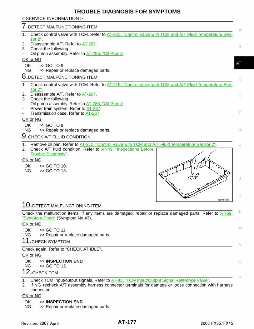
TROUBLE DIAGNOSIS FOR SYMPTOMS
D
E
F
G
H
I
J
K
L
M
A
B
T
N
O
P
< SERVICE INFORMATION >
A
7.DETECT MALFUNCTIONING ITEM
1. Check control valve with TCM. Refer to AT-215, "Control Valve with TCM and A/T Fluid Temperature Sen-sor 2".
2. Disassemble A/T. Refer to AT-267.3. Check the following.- Oil pump assembly. Refer to AT-285, "Oil Pump".OK or NGOK >> GO TO 9.NG >> Repair or replace damaged parts.
8.DETECT MALFUNCTIONING ITEM
1. Check control valve with TCM. Refer to AT-215, "Control Valve with TCM and A/T Fluid Temperature Sen-sor 2".
2. Disassemble A/T. Refer to AT-267.3. Check the following.- Oil pump assembly. Refer to AT-285, "Oil Pump".- Power train system. Refer to AT-267.- Transmission case. Refer to AT-267.OK or NGOK >> GO TO 9.NG >> Repair or replace damaged parts.
9.CHECK A/T FLUID CONDITION
1. Remove oil pan. Refer to AT-215, "Control Valve with TCM and A/T Fluid Temperature Sensor 2".2. Check A/T fluid condition. Refer to AT-49, "Inspections Before
Trouble Diagnosis".OK or NGOK >> GO TO 10.NG >> GO TO 13.
10.DETECT MALFUNCTIONING ITEM
Check the malfunction items. If any items are damaged, repair or replace damaged parts. Refer to AT-59,"Symptom Chart" (Symptom No.43).OK or NGOK >> GO TO 11.NG >> Repair or replace damaged parts.
11.CHECK SYMPTOM
Check again. Refer to “CHECK AT IDLE”.OK or NGOK >> INSPECTION ENDNG >> GO TO 12.
12.CHECK TCM
1. Check TCM input/output signals. Refer to AT-83, "TCM Input/Output Signal Reference Value".2. If NG, recheck A/T assembly harness connector terminals for damage or loose connection with harness
connector.OK or NGOK >> INSPECTION ENDNG >> Repair or replace damaged parts.
SCIA5199E
AT-177Revision: 2007 April 2008 FX35/FX45

TROUBLE DIAGNOSIS FOR SYMPTOMS
< SERVICE INFORMATION >13.DETECT MALFUNCTIONING ITEM
Check the malfunction items. If any items are damaged, repair or replace damaged parts. Refer to AT-59,"Symptom Chart" (Symptom No.43).OK or NGOK >> GO TO 11.NG >> Repair or replace damaged parts.
Vehicle Does Not Creep Forward in "D" Position INFOID:0000000001327367
SYMPTOM:Vehicle does not creep forward when selecting “D” position.
DIAGNOSTIC PROCEDURE
1.CHECK SELF-DIAGNOSTIC RESULTS
With CONSULT-III• Perform self-diagnosis.
Without CONSULT-III• Perform self-diagnosis. Refer to AT-91, "Diagnosis Procedure without CONSULT-III".Is any malfunction detected by self-diagnostic results?YES >> Check the malfunctioning system. Refer to AT-84, "CONSULT-III Function (TRANSMISSION)",
AT-91, "Diagnosis Procedure without CONSULT-III".NO >> GO TO 2.
2.CHECK A/T POSITION
Check the A/T position. Refer to AT-207, "Checking of A/T Position".OK or NGOK >> GO TO 3.NG >> Adjust A/T position. Refer to AT-207, "Adjustment of A/T
Position".
3.CHECK A/T FLUID LEVEL
Check A/T fluid level. Refer to AT-11, "Checking A/T Fluid".OK or NGOK >> GO TO 4.NG >> Refill ATF.
4.CHECK STALL TEST
SCIA2119E
SAT638A
AT-178Revision: 2007 April 2008 FX35/FX45

TROUBLE DIAGNOSIS FOR SYMPTOMS
D
E
F
G
H
I
J
K
L
M
A
B
T
N
O
P
< SERVICE INFORMATION >
A
Check stall revolution with selector lever in “D” position. Refer to AT-49, "Inspections Before Trouble Diagnosis".OK or NGOK >> GO TO 5.NG >> GO TO 7.
5.CHECK LINE PRESSURE
Check line pressure at idle with selector lever in “D” position. Referto AT-49, "Inspections Before Trouble Diagnosis".OK or NGOK >> GO TO 8.NG-1 >> Line pressure high: GO TO 6.NG-2 >> Line pressure low: GO TO 7.
6.DETECT MALFUNCTIONING ITEM
1. Check control valve with TCM. Refer to AT-215, "Control Valve with TCM and A/T Fluid Temperature Sen-sor 2".
2. Disassemble A/T. Refer to AT-267.3. Check the following.- Oil pump assembly. Refer to AT-285, "Oil Pump".OK or NGOK >> GO TO 8.NG >> Repair or replace damaged parts.
7.DETECT MALFUNCTIONING ITEM
1. Check control valve with TCM. Refer to AT-215, "Control Valve with TCM and A/T Fluid Temperature Sen-sor 2".
2. Disassemble A/T. Refer to AT-267.3. Check the following.- Oil pump assembly. Refer to AT-285, "Oil Pump".- Power train system. Refer to AT-267.- Transmission case. Refer to AT-267.OK or NGOK >> GO TO 8.NG >> Repair or replace damaged parts.
8.CHECK A/T FLUID CONDITION
1. Remove oil pan. Refer to AT-215, "Control Valve with TCM and A/T Fluid Temperature Sensor 2".
SAT493G
SAT494G
AT-179Revision: 2007 April 2008 FX35/FX45

TROUBLE DIAGNOSIS FOR SYMPTOMS
< SERVICE INFORMATION >2. Check A/T fluid condition. Refer to AT-49, "Inspections BeforeTrouble Diagnosis".OK or NGOK >> GO TO 9.NG >> GO TO 12.
9.DETECT MALFUNCTIONING ITEM
Check the malfunction items. If any items are damaged, repair or replace damaged parts. Refer to AT-59,"Symptom Chart" (Symptom No.43).OK or NGOK >> GO TO 10.NG >> Repair or replace damaged parts.
10.CHECK SYMPTOM
Check again. Refer to “CHECK AT IDLE”.OK or NGOK >> INSPECTION ENDNG >> GO TO 11.
11.CHECK TCM
1. Check TCM input/output signals. Refer to AT-83, "TCM Input/Output Signal Reference Value".2. If NG, recheck A/T assembly harness connector terminals for damage or loose connection with harness
connector.OK or NGOK >> INSPECTION ENDNG >> Repair or replace damaged parts.
12.DETECT MALFUNCTIONING ITEM
Check the malfunction items. If any items are damaged, repair or replace damaged parts. Refer to AT-59,"Symptom Chart" (Symptom No.43).OK or NGOK >> GO TO 10.NG >> Repair or replace damaged parts.
Vehicle Cannot Be Started from D1 INFOID:0000000001327368
SYMPTOM:Vehicle cannot be started from D1 on “Cruise Test - Part 1” and “Cruise Test - Part2”.
DIAGNOSTIC PROCEDURE
1.CONFIRM THE SYMPTOM
Check if vehicle creeps in “R” position.OK or NGOK >> GO TO 2.NG >> Refer to AT-175, "Vehicle Does Not Creep Backward in "R" Position".
2.CHECK SELF-DIAGNOSTIC RESULTS
With CONSULT-III• Perform self-diagnosis.
Without CONSULT-III
SCIA5199E
AT-180Revision: 2007 April 2008 FX35/FX45
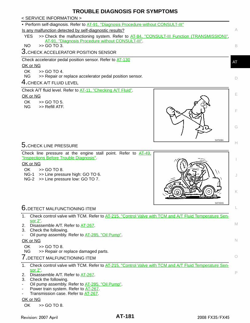
TROUBLE DIAGNOSIS FOR SYMPTOMS
D
E
F
G
H
I
J
K
L
M
A
B
T
N
O
P
< SERVICE INFORMATION >
A
• Perform self-diagnosis. Refer to AT-91, "Diagnosis Procedure without CONSULT-III"Is any malfunction detected by self-diagnostic results?YES >> Check the malfunctioning system. Refer to AT-84, "CONSULT-III Function (TRANSMISSION)",
AT-91, "Diagnosis Procedure without CONSULT-III".NO >> GO TO 3.
3.CHECK ACCELERATOR POSITION SENSOR
Check accelerator pedal position sensor. Refer to AT-130OK or NGOK >> GO TO 4.NG >> Repair or replace accelerator pedal position sensor.
4.CHECK A/T FLUID LEVEL
Check A/T fluid level. Refer to AT-11, "Checking A/T Fluid".OK or NGOK >> GO TO 5.NG >> Refill ATF.
5.CHECK LINE PRESSURE
Check line pressure at the engine stall point. Refer to AT-49,"Inspections Before Trouble Diagnosis".OK or NGOK >> GO TO 8.NG-1 >> Line pressure high: GO TO 6.NG-2 >> Line pressure low: GO TO 7.
6.DETECT MALFUNCTIONING ITEM
1. Check control valve with TCM. Refer to AT-215, "Control Valve with TCM and A/T Fluid Temperature Sen-sor 2".
2. Disassemble A/T. Refer to AT-267.3. Check the following.- Oil pump assembly. Refer to AT-285, "Oil Pump".OK or NGOK >> GO TO 8.NG >> Repair or replace damaged parts.
7.DETECT MALFUNCTIONING ITEM
1. Check control valve with TCM. Refer to AT-215, "Control Valve with TCM and A/T Fluid Temperature Sen-sor 2".
2. Disassemble A/T. Refer to AT-267.3. Check the following.- Oil pump assembly. Refer to AT-285, "Oil Pump".- Power train system. Refer to AT-267.- Transmission case. Refer to AT-267.OK or NGOK >> GO TO 8.
SAT638A
SAT494G
AT-181Revision: 2007 April 2008 FX35/FX45

TROUBLE DIAGNOSIS FOR SYMPTOMS
< SERVICE INFORMATION >NG >> Repair or replace damaged parts.8.CHECK A/T FLUID CONDITION
1. Remove oil pan. Refer to AT-215, "Control Valve with TCM and A/T Fluid Temperature Sensor 2".2. Check A/T fluid condition. Refer to AT-49, "Inspections Before
Trouble Diagnosis".OK or NGOK >> GO TO 9.NG >> GO TO 12.
9.DETECT MALFUNCTIONING ITEM
Check the malfunction items. If any items are damaged, repair or replace damaged parts. Refer to AT-59,"Symptom Chart" (Symptom No.23).OK or NGOK >> GO TO 10.NG >> Repair or replace damaged parts.
10.CHECK SYMPTOM
Check again. Refer to AT-53, "Road Test".OK or NGOK >> INSPECTION ENDNG >> GO TO 11.
11.CHECK TCM
1. Check TCM input/output signals. Refer to AT-83, "TCM Input/Output Signal Reference Value".2. If NG, recheck A/T assembly harness connector terminals for damage or loose connection with harness
connector.OK or NGOK >> INSPECTION ENDNG >> Repair or replace damaged parts.
12.DETECT MALFUNCTIONING ITEM
Check the malfunction items. If any items are damaged, repair or replace damaged parts. Refer to AT-59,"Symptom Chart" (Symptom No.23).OK or NGOK >> GO TO 10.NG >> Repair or replace damaged parts.
A/T Does Not Shift: D1→ D2 INFOID:0000000001327369
SYMPTOM:The vehicle does not shift-up from the D1 to D2 gear at the specified speed.
DIAGNOSTIC PROCEDURE
1.CONFIRM THE SYMPTOM
Check if vehicle creeps forward in “D” position and vehicle can be started from D1.
OK or NGOK >> GO TO 2.NG >> Refer to AT-178, "Vehicle Does Not Creep Forward in "D" Position", AT-180, "Vehicle Cannot Be
Started from D1".
2.CHECK SELF-DIAGNOSTIC RESULTS
SCIA5199E
AT-182Revision: 2007 April 2008 FX35/FX45

TROUBLE DIAGNOSIS FOR SYMPTOMS
D
E
F
G
H
I
J
K
L
M
A
B
T
N
O
P
< SERVICE INFORMATION >
A
With CONSULT-III• Perform self-diagnosis.
Without CONSULT-III• Perform self-diagnosis. Refer to AT-91, "Diagnosis Procedure without CONSULT-III".Is any malfunction detected by self-diagnostic results?YES >> Check the malfunctioning system. Refer to AT-84, "CONSULT-III Function (TRANSMISSION)",
AT-91, "Diagnosis Procedure without CONSULT-III".NO >> GO TO 3.
3.CHECK A/T FLUID LEVEL
Check A/T fluid level. Refer to AT-11, "Checking A/T Fluid".OK or NGOK >> GO TO 4.NG >> Refill ATF.
4.CHECK LINE PRESSURE
Check line pressure at the engine stall point. Refer to AT-49,"Inspections Before Trouble Diagnosis".OK or NGOK >> GO TO 7.NG-1 >> Line pressure high: GO TO 5.NG-2 >> Line pressure low: GO TO 6.
5.DETECT MALFUNCTIONING ITEM
1. Check control valve with TCM. Refer to AT-215, "Control Valve with TCM and A/T Fluid Temperature Sen-sor 2".
2. Disassemble A/T. Refer to AT-267.3. Check the following.- Oil pump assembly. Refer to AT-285, "Oil Pump".OK or NGOK >> GO TO 7.NG >> Repair or replace damaged parts.
6.DETECT MALFUNCTIONING ITEM
1. Check control valve with TCM. Refer to AT-215, "Control Valve with TCM and A/T Fluid Temperature Sen-sor 2".
2. Disassemble A/T. Refer to AT-267.3. Check the following.- Oil pump assembly. Refer to AT-285, "Oil Pump".- Power train system. Refer to AT-267.- Transmission case. Refer to AT-267.OK or NGOK >> GO TO 7.NG >> Repair or replace damaged parts.
SAT638A
SAT494G
AT-183Revision: 2007 April 2008 FX35/FX45

TROUBLE DIAGNOSIS FOR SYMPTOMS
< SERVICE INFORMATION >7.CHECK A/T FLUID CONDITION
1. Remove oil pan. Refer to AT-215, "Control Valve with TCM and A/T Fluid Temperature Sensor 2".2. Check A/T fluid condition. Refer to AT-49, "Inspections Before
Trouble Diagnosis".OK or NGOK >> GO TO 8.NG >> GO TO 11.
8.DETECT MALFUNCTIONING ITEM
Check the malfunction items. If any items are damaged, repair or replace damaged parts. Refer to AT-59,"Symptom Chart" (Symptom No.10).OK or NGOK >> GO TO 9.NG >> Repair or replace damaged parts.
9.CHECK SYMPTOM
Check again. Refer to AT-53, "Road Test".OK or NGOK >> INSPECTION ENDNG >> GO TO 10.
10.CHECK TCM
1. Check TCM input/output signals. Refer to AT-83, "TCM Input/Output Signal Reference Value".2. If NG, recheck A/T assembly harness connector terminals for damage or loose connection with harness
connector.OK or NGOK >> INSPECTION ENDNG >> Repair or replace damaged parts.
11.DETECT MALFUNCTIONING ITEM
Check the malfunction items. If any items are damaged, repair or replace damaged parts. Refer to AT-59,"Symptom Chart" (Symptom No.10).OK or NGOK >> GO TO 9.NG >> Repair or replace damaged parts.
A/T Does Not Shift: D2→ D3 INFOID:0000000001327370
SYMPTOM:The vehicle does not shift-up from D2 to D3 gear at the specified speed.
DIAGNOSTIC PROCEDURE
1.CONFIRM THE SYMPTOM
Check if vehicle creeps forward in “D” position and vehicle can be started from D1.
OK or NGOK >> GO TO 2.NG >> Refer to AT-178, "Vehicle Does Not Creep Forward in "D" Position", AT-180, "Vehicle Cannot Be
Started from D1".
2.CHECK SELF-DIAGNOSTIC RESULTS
SCIA5199E
AT-184Revision: 2007 April 2008 FX35/FX45

TROUBLE DIAGNOSIS FOR SYMPTOMS
D
E
F
G
H
I
J
K
L
M
A
B
T
N
O
P
< SERVICE INFORMATION >
A
With CONSULT-III• Perform self-diagnosis.
Without CONSULT-III• Perform self-diagnosis. Refer to AT-91, "Diagnosis Procedure without CONSULT-III".Is any malfunction detected by self-diagnostic results?YES >> Check the malfunctioning system. Refer to AT-84, "CONSULT-III Function (TRANSMISSION)",
AT-91, "Diagnosis Procedure without CONSULT-III".NO >> GO TO 3.
3.CHECK A/T FLUID LEVEL
Check A/T fluid level. Refer to AT-11, "Checking A/T Fluid".OK or NGOK >> GO TO 4.NG >> Refill ATF.
4.CHECK LINE PRESSURE
Check line pressure at the engine stall point. Refer to AT-49,"Inspections Before Trouble Diagnosis".OK or NGOK >> GO TO 7.NG-1 >> Line pressure high: GO TO 5.NG-2 >> Line pressure low: GO TO 6.
5.DETECT MALFUNCTIONING ITEM
1. Check control valve with TCM. Refer to AT-215, "Control Valve with TCM and A/T Fluid Temperature Sen-sor 2".
2. Disassemble A/T. Refer to AT-267.3. Check the following.- Oil pump assembly. Refer to AT-285, "Oil Pump".OK or NGOK >> GO TO 7.NG >> Repair or replace damaged parts.
6.DETECT MALFUNCTIONING ITEM
1. Check control valve with TCM. Refer to AT-215, "Control Valve with TCM and A/T Fluid Temperature Sen-sor 2".
2. Disassemble A/T. Refer to AT-267.3. Check the following.- Oil pump assembly. Refer to AT-285, "Oil Pump".- Power train system. Refer to AT-267.- Transmission case. Refer to AT-267.OK or NGOK >> GO TO 7.NG >> Repair or replace damaged parts.
SAT638A
SAT494G
AT-185Revision: 2007 April 2008 FX35/FX45

TROUBLE DIAGNOSIS FOR SYMPTOMS
< SERVICE INFORMATION >7.CHECK A/T FLUID CONDITION
1. Remove oil pan. Refer to AT-215, "Control Valve with TCM and A/T Fluid Temperature Sensor 2".2. Check A/T fluid condition. Refer to AT-49, "Inspections Before
Trouble Diagnosis".OK or NGOK >> GO TO 8.NG >> GO TO 11.
8.DETECT MALFUNCTIONING ITEM
Check the malfunction items. If any items are damaged, repair or replace damaged parts. Refer to AT-59,"Symptom Chart" (Symptom No.11).OK or NGOK >> GO TO 9.NG >> Repair or replace damaged parts.
9.CHECK SYMPTOM
Check again. Refer to AT-53, "Road Test".OK or NGOK >> INSPECTION ENDNG >> GO TO 10.
10.CHECK TCM
1. Check TCM input/output signals. Refer to AT-83, "TCM Input/Output Signal Reference Value".2. If NG, recheck A/T assembly harness connector terminals for damage or loose connection with harness
connector.OK or NGOK >> INSPECTION ENDNG >> Repair or replace damaged parts.
11.DETECT MALFUNCTIONING ITEM
Check the malfunction items. If any items are damaged, repair or replace damaged parts. Refer to AT-59,"Symptom Chart" (Symptom No.11).OK or NGOK >> GO TO 9.NG >> Repair or replace damaged parts.
A/T Does Not Shift: D3→ D4 INFOID:0000000001327371
SYMPTOM:The vehicle does not shift-up from the D3 to D4 gear at the specified speed.
DIAGNOSTIC PROCEDURE
1.CONFIRM THE SYMPTOM
Check if vehicle creeps forward in “D” position and vehicle can be started from D1.
OK or NGOK >> GO TO 2.NG >> Refer to AT-178, "Vehicle Does Not Creep Forward in "D" Position", AT-180, "Vehicle Cannot Be
Started from D1".
2.CHECK SELF-DIAGNOSTIC RESULTS
SCIA5199E
AT-186Revision: 2007 April 2008 FX35/FX45

TROUBLE DIAGNOSIS FOR SYMPTOMS
D
E
F
G
H
I
J
K
L
M
A
B
T
N
O
P
< SERVICE INFORMATION >
A
With CONSULT-III• Perform self-diagnosis.
Without CONSULT-III• Perform self-diagnosis. Refer to AT-91, "Diagnosis Procedure without CONSULT-III".Is any malfunction detected by self-diagnostic results?YES >> Check the malfunctioning system. Refer to AT-84, "CONSULT-III Function (TRANSMISSION)",
AT-91, "Diagnosis Procedure without CONSULT-III".NO >> GO TO 3.
3.CHECK A/T FLUID LEVEL
Check A/T fluid level. Refer to AT-11, "Checking A/T Fluid".OK or NGOK >> GO TO 4.NG >> Refill ATF.
4.CHECK LINE PRESSURE
Check line pressure at the engine stall point. Refer to AT-49,"Inspections Before Trouble Diagnosis".OK or NGOK >> GO TO 7.NG-1 >> Line pressure high: GO TO 5.NG-2 >> Line pressure low: GO TO 6.
5.DETECT MALFUNCTIONING ITEM
1. Check control valve with TCM. Refer to AT-215, "Control Valve with TCM and A/T Fluid Temperature Sen-sor 2".
2. Disassemble A/T. Refer to AT-267.3. Check the following.- Oil pump assembly. Refer to AT-285, "Oil Pump".OK or NGOK >> GO TO 7.NG >> Repair or replace damaged parts.
6.DETECT MALFUNCTIONING ITEM
1. Check control valve with TCM. Refer to AT-215, "Control Valve with TCM and A/T Fluid Temperature Sen-sor 2".
2. Disassemble A/T. Refer to AT-267.3. Check the following.- Oil pump assembly. Refer to AT-285, "Oil Pump".- Power train system. Refer to AT-267.- Transmission case. Refer to AT-267.OK or NGOK >> GO TO 7.NG >> Repair or replace damaged parts.
SAT638A
SAT494G
AT-187Revision: 2007 April 2008 FX35/FX45

TROUBLE DIAGNOSIS FOR SYMPTOMS
< SERVICE INFORMATION >7.CHECK A/T FLUID CONDITION
1. Remove oil pan. Refer to AT-215, "Control Valve with TCM and A/T Fluid Temperature Sensor 2".2. Check A/T fluid condition. Refer to AT-49, "Inspections Before
Trouble Diagnosis".OK or NGOK >> GO TO 8.NG >> GO TO 11.
8.DETECT MALFUNCTIONING ITEM
Check the malfunction items. If any items are damaged, repair or replace damaged parts. Refer to AT-59,"Symptom Chart" (Symptom No.12).OK or NGOK >> GO TO 9.NG >> Repair or replace damaged parts.
9.CHECK SYMPTOM
Check again. Refer to AT-53, "Road Test".OK or NGOK >> INSPECTION ENDNG >> GO TO 10.
10.CHECK TCM
1. Check TCM input/output signals. Refer to AT-83, "TCM Input/Output Signal Reference Value".2. If NG, recheck A/T assembly harness connector terminals for damage or loose connection with harness
connector.OK or NGOK >> INSPECTION ENDNG >> Repair or replace damaged parts.
11.DETECT MALFUNCTIONING ITEM
Check the malfunction items. If any items are damaged, repair or replace damaged parts. Refer to AT-59,"Symptom Chart" (Symptom No.12).OK or NGOK >> GO TO 9.NG >> Repair or replace damaged parts.
A/T Does Not Shift: D4→ D5 INFOID:0000000001327372
SYMPTOM:• The vehicle does not shift-up from the D4 to D5 gear at the specified speed.• The vehicle does not shift-up from the D4 to D5 gear unless A/T is warmed up.
DIAGNOSTIC PROCEDURE
1.CONFIRM THE SYMPTOM
Check if vehicle creeps forward in “D” position and vehicle can be started from D1.
OK or NGOK >> GO TO 2.NG >> Refer to AT-178, "Vehicle Does Not Creep Forward in "D" Position", AT-180, "Vehicle Cannot Be
Started from D1".
2.CHECK SELF-DIAGNOSTIC RESULTS
SCIA5199E
AT-188Revision: 2007 April 2008 FX35/FX45

TROUBLE DIAGNOSIS FOR SYMPTOMS
D
E
F
G
H
I
J
K
L
M
A
B
T
N
O
P
< SERVICE INFORMATION >
A
With CONSULT-III• Perform self-diagnosis.
Without CONSULT-III• Perform self-diagnosis. Refer to AT-91, "Diagnosis Procedure without CONSULT-III".Is any malfunction detected by self-diagnostic results?YES >> Check the malfunctioning system. Refer to AT-84, "CONSULT-III Function (TRANSMISSION)",
AT-91, "Diagnosis Procedure without CONSULT-III".NO >> GO TO 3.
3.CHECK A/T FLUID LEVEL
Check A/T fluid level. Refer to AT-11, "Checking A/T Fluid".OK or NGOK >> GO TO 4.NG >> Refill ATF.
4.CHECK LINE PRESSURE
Check line pressure at the engine stall point. Refer to AT-49,"Inspections Before Trouble Diagnosis".OK or NGOK >> GO TO 7.NG-1 >> Line pressure high: GO TO 5.NG-2 >> Line pressure low: GO TO 6.
5.DETECT MALFUNCTIONING ITEM
1. Check control valve with TCM. Refer to AT-215, "Control Valve with TCM and A/T Fluid Temperature Sen-sor 2".
2. Disassemble A/T. Refer to AT-267.3. Check the following.- Oil pump assembly. Refer to AT-285, "Oil Pump".OK or NGOK >> GO TO 7.NG >> Repair or replace damaged parts.
6.DETECT MALFUNCTIONING ITEM
1. Check control valve with TCM. Refer to AT-215, "Control Valve with TCM and A/T Fluid Temperature Sen-sor 2".
2. Disassemble A/T. Refer to AT-267.3. Check the following.- Oil pump assembly. Refer to AT-285, "Oil Pump".- Power train system. Refer to AT-267.- Transmission case. Refer to AT-267.OK or NGOK >> GO TO 7.NG >> Repair or replace damaged parts.
SAT638A
SAT494G
AT-189Revision: 2007 April 2008 FX35/FX45

TROUBLE DIAGNOSIS FOR SYMPTOMS
< SERVICE INFORMATION >7.CHECK A/T FLUID CONDITION
1. Remove oil pan. Refer to AT-215, "Control Valve with TCM and A/T Fluid Temperature Sensor 2".2. Check A/T fluid condition. Refer to AT-49, "Inspections Before
Trouble Diagnosis".OK or NGOK >> GO TO 8.NG >> GO TO 11.
8.DETECT MALFUNCTIONING ITEM
Check the malfunction items. If any items are damaged, repair or replace damaged parts. Refer to AT-59,"Symptom Chart" (Symptom No.13).OK or NGOK >> GO TO 9.NG >> Repair or replace damaged parts.
9.CHECK SYMPTOM
Check again. Refer to AT-53, "Road Test".OK or NGOK >> INSPECTION ENDNG >> GO TO 10.
10.CHECK TCM
1. Check TCM input/output signals. Refer to AT-83, "TCM Input/Output Signal Reference Value".2. If NG, recheck A/T assembly harness connector terminals for damage or loose connection with harness
connector.OK or NGOK >> INSPECTION ENDNG >> Repair or replace damaged parts.
11.DETECT MALFUNCTIONING ITEM
Check the malfunction items. If any items are damaged, repair or replace damaged parts. Refer to AT-59,"Symptom Chart" (Symptom No.13). OK or NGOK >> GO TO 9.NG >> Repair or replace damaged parts.
A/T Does Not Lock-up INFOID:0000000001327373
SYMPTOM:A/T does not lock-up at the specified speed.
DIAGNOSTIC PROCEDURE
1.CHECK SELF-DIAGNOSTIC RESULTS
With CONSULT-III• Perform self-diagnosis.
Without CONSULT-III• Perform self-diagnosis. Refer to AT-91, "Diagnosis Procedure without CONSULT-III".Is any malfunction detected by self-diagnostic results?
SCIA5199E
AT-190Revision: 2007 April 2008 FX35/FX45

TROUBLE DIAGNOSIS FOR SYMPTOMS
D
E
F
G
H
I
J
K
L
M
A
B
T
N
O
P
< SERVICE INFORMATION >
A
YES >> Check the malfunctioning system. Refer to AT-84, "CONSULT-III Function (TRANSMISSION)",AT-91, "Diagnosis Procedure without CONSULT-III".
NO >> GO TO 2.
2.CHECK A/T FLUID LEVEL
Check A/T fluid level. Refer to AT-11, "Checking A/T Fluid".OK or NGOK >> GO TO 3.NG >> Refill ATF.
3.CHECK LINE PRESSURE
Check line pressure at the engine stall point. Refer to AT-49,"Inspections Before Trouble Diagnosis".OK or NGOK >> GO TO 6.NG-1 >> Line pressure high: GO TO 4.NG-2 >> Line pressure low: GO TO 5.
4.DETECT MALFUNCTIONING ITEM
1. Check control valve with TCM. Refer to AT-215, "Control Valve with TCM and A/T Fluid Temperature Sen-sor 2".
2. Disassemble A/T. Refer to AT-267.3. Check the following.- Oil pump assembly. Refer to AT-285, "Oil Pump".OK or NGOK >> GO TO 6.NG >> Repair or replace damaged parts.
5.DETECT MALFUNCTIONING ITEM
1. Check control valve with TCM. Refer to AT-215, "Control Valve with TCM and A/T Fluid Temperature Sen-sor 2".
2. Disassemble A/T. Refer to AT-267.3. Check the following.- Oil pump assembly. Refer to AT-285, "Oil Pump".- Power train system. Refer to AT-267.- Transmission case. Refer to AT-267.OK or NGOK >> GO TO 6.NG >> Repair or replace damaged parts.
6.CHECK A/T FLUID CONDITION
1. Remove oil pan. Refer to AT-215, "Control Valve with TCM and A/T Fluid Temperature Sensor 2".
SAT638A
SAT494G
AT-191Revision: 2007 April 2008 FX35/FX45

TROUBLE DIAGNOSIS FOR SYMPTOMS
< SERVICE INFORMATION >2. Check A/T fluid condition. Refer to AT-49, "Inspections BeforeTrouble Diagnosis".OK or NGOK >> GO TO 7.NG >> GO TO 10.
7.DETECT MALFUNCTIONING ITEM
Check the malfunction items. If any items are damaged, repair or replace damaged parts. Refer to AT-59,"Symptom Chart" (Symptom No.24).OK or NGOK >> GO TO 8.NG >> Repair or replace damaged parts.
8.CHECK SYMPTOM
Check again. Refer to AT-53, "Road Test".OK or NGOK >> INSPECTION ENDNG >> GO TO 9.
9.CHECK TCM
1. Check TCM input/output signals. Refer to AT-83, "TCM Input/Output Signal Reference Value".2. If NG, recheck A/T assembly harness connector terminals for damage or loose connection with harness
connector.OK or NGOK >> INSPECTION ENDNG >> Repair or replace damaged parts.
10.DETECT MALFUNCTIONING ITEM
Check the malfunction items. If any items are damaged, repair or replace damaged parts. Refer to AT-59,"Symptom Chart" (Symptom No.24).OK or NGOK >> GO TO 8.NG >> Repair or replace damaged parts.
A/T Does Not Hold Lock-up Condition INFOID:0000000001327374
SYMPTOM:The lock-up condition cannot be maintained for more than 30 seconds.
DIAGNOSTIC PROCEDURE
1.CHECK SELF-DIAGNOSTIC RESULTS
With CONSULT-III• Perform self-diagnosis.
Without CONSULT-III• Perform self-diagnosis. Refer to AT-91, "Diagnosis Procedure without CONSULT-III".Is any malfunction detected by self-diagnostic results?YES >> Check the malfunctioning system. Refer to AT-84, "CONSULT-III Function (TRANSMISSION)",
AT-91, "Diagnosis Procedure without CONSULT-III".NO >> GO TO 2.
SCIA5199E
AT-192Revision: 2007 April 2008 FX35/FX45

TROUBLE DIAGNOSIS FOR SYMPTOMS
D
E
F
G
H
I
J
K
L
M
A
B
T
N
O
P
< SERVICE INFORMATION >
A
2.CHECK A/T FLUID LEVEL
Check A/T fluid level. Refer to AT-11, "Checking A/T Fluid".OK or NGOK >> GO TO 3.NG >> Refill ATF.
3.CHECK A/T FLUID CONDITION
1. Remove oil pan. Refer to AT-215, "Control Valve with TCM and A/T Fluid Temperature Sensor 2".2. Check A/T fluid condition. Refer to AT-49, "Inspections Before
Trouble Diagnosis".OK or NGOK >> GO TO 4.NG >> GO TO 7.
4.DETECT MALFUNCTIONING ITEM
Check the malfunction items. If any items are damaged, repair or replace damaged parts. Refer to AT-59,"Symptom Chart" (Symptom No.25).OK or NGOK >> GO TO 5.NG >> Repair or replace damaged parts.
5.CHECK SYMPTOM
Check again. Refer to AT-53, "Road Test".OK or NGOK >> INSPECTION ENDNG >> GO TO 6.
6.CHECK TCM
1. Check TCM input/output signals. Refer to AT-83, "TCM Input/Output Signal Reference Value".2. If NG, recheck A/T assembly harness connector terminals for damage or loose connection with harness
connector.OK or NGOK >> INSPECTION ENDNG >> Repair or replace damaged parts.
7.DETECT MALFUNCTIONING ITEM
Check the malfunction items. If any items are damaged, repair or replace damaged parts. Refer to AT-59,"Symptom Chart" (Symptom No.25).OK or NGOK >> GO TO 5.NG >> Repair or replace damaged parts.
SAT638A
SCIA5199E
AT-193Revision: 2007 April 2008 FX35/FX45

TROUBLE DIAGNOSIS FOR SYMPTOMS
< SERVICE INFORMATION >Lock-up Is Not Released INFOID:0000000001327375
SYMPTOM:The lock-up condition cannot be cancelled even after releasing the accelerator pedal.
DIAGNOSTIC PROCEDURE
1.CHECK SELF-DIAGNOSTIC RESULTS
With CONSULT-III• Perform self-diagnosis.
Without CONSULT-III• Perform self-diagnosis. Refer to AT-91, "Diagnosis Procedure without CONSULT-III".Is any malfunction detected by self-diagnostic results?YES >> Check the malfunctioning system. Refer to AT-84, "CONSULT-III Function (TRANSMISSION)",
AT-91, "Diagnosis Procedure without CONSULT-III".NO >> GO TO 2.
2.CHECK SYMPTOM
Check again. Refer to AT-53, "Road Test".OK or NGOK >> INSPECTION ENDNG >> GO TO 3.
3.CHECK TCM
1. Check TCM input/output signals. Refer to AT-83, "TCM Input/Output Signal Reference Value".2. If NG, recheck A/T assembly harness connector terminals for damage or loose connection with harness
connector.OK or NGOK >> INSPECTION ENDNG >> Repair or replace damaged parts.
Engine Speed Does Not Return to Idle INFOID:0000000001327376
SYMPTOM:When a shift-down is performed, the engine speed does not smoothly return to the idling speed.
DIAGNOSTIC PROCEDURE
1.CHECK A/T FLUID LEVEL
Check A/T fluid level. Refer to AT-11, "Checking A/T Fluid".OK or NGOK >> GO TO 2.NG >> Refill ATF.
2.CHECK SELF-DIAGNOSTIC RESULTS
With CONSULT-III• Perform self-diagnosis.
Without CONSULT-III• Perform self-diagnosis. Refer to AT-91, "Diagnosis Procedure without CONSULT-III".
SAT638A
AT-194Revision: 2007 April 2008 FX35/FX45

TROUBLE DIAGNOSIS FOR SYMPTOMS
D
E
F
G
H
I
J
K
L
M
A
B
T
N
O
P
< SERVICE INFORMATION >
A
Is any malfunction detected by self-diagnostic results?YES >> Check the malfunctioning system. Refer to AT-84, "CONSULT-III Function (TRANSMISSION)",
AT-91, "Diagnosis Procedure without CONSULT-III".NO >> GO TO 3.
3.CHECK A/T FLUID CONDITION
1. Remove oil pan. Refer to AT-215, "Control Valve with TCM and A/T Fluid Temperature Sensor 2".2. Check A/T fluid condition. Refer to AT-49, "Inspections Before
Trouble Diagnosis".OK or NGOK >> GO TO 4.NG >> GO TO 7.
4.DETECT MALFUNCTIONING ITEM
Check the malfunction items. If any items are damaged, repair or replace damaged parts. Refer to AT-59,"Symptom Chart" (Symptom No.72).OK or NGOK >> GO TO 5.NG >> Repair or replace damaged parts.
5.CHECK SYMPTOM
Check again. Refer to AT-53, "Road Test".OK or NGOK >> INSPECTION ENDNG >> GO TO 6.
6.CHECK TCM
1. Check TCM input/output signals. Refer to AT-83, "TCM Input/Output Signal Reference Value".2. If NG, recheck A/T assembly harness connector terminals for damage or loose connection with harness
connector.OK or NGOK >> INSPECTION ENDNG >> Repair or replace damaged parts.
7.DETECT MALFUNCTIONING ITEM
Check the malfunction items. If any items are damaged, repair or replace damaged parts. Refer to AT-59,"Symptom Chart" (Symptom No.72).OK or NGOK >> GO TO 5.NG >> Repair or replace damaged parts.
Cannot Be Changed to Manual Mode INFOID:0000000001327377
SYMPTOM:Does not change to manual mode when manual shift gate is used.
DIAGNOSTIC PROCEDURE
1.CHECK MANUAL MODE SWITCH
Check the manual mode switch. Refer to AT-155.OK or NGOK >> GO TO 2.
SCIA5199E
AT-195Revision: 2007 April 2008 FX35/FX45

TROUBLE DIAGNOSIS FOR SYMPTOMS
< SERVICE INFORMATION >NG >> Repair or replace damaged parts.2.CHECK SELF-DIAGNOSIS RESULTS
With CONSULT-III• Perform self-diagnosis.
Without CONSULT-III• Perform self-diagnosis. Refer to AT-91, "Diagnosis Procedure without CONSULT-III".Is any malfunction detected by self-diagnostic results?YES >> Check the malfunctioning system. Refer to AT-84, "CONSULT-III Function (TRANSMISSION)",
AT-91, "Diagnosis Procedure without CONSULT-III".NO >> INSPECTION END
A/T Does Not Shift: 5th Gear → 4th Gear INFOID:0000000001327378
SYMPTOM:When shifted from M5 to M4 position in manual mode, does not downshift from 5th to 4th gear.
DIAGNOSTIC PROCEDURE
1.CHECK SELF-DIAGNOSTIC RESULTS
With CONSULT-III• Perform self-diagnosis.
Without CONSULT-III• Perform self-diagnosis. Refer to AT-91, "Diagnosis Procedure without CONSULT-III".Is any malfunction detected by self-diagnostic results?YES >> Check the malfunctioning system. Refer to AT-84, "CONSULT-III Function (TRANSMISSION)",
AT-91, "Diagnosis Procedure without CONSULT-III".NO >> GO TO 2.
2.CHECK A/T FLUID LEVEL
Check A/T fluid level. Refer to AT-11, "Checking A/T Fluid".OK or NGOK >> GO TO 3.NG >> Refill ATF.
3.CHECK A/T POSITION
Check the A/T position. Refer to AT-207, "Checking of A/T Position".OK or NGOK >> GO TO 4.NG >> Adjust A/T position. Refer to AT-207, "Adjustment of A/T
Position".
4.CHECK MANUAL MODE SWITCH
SAT638A
SCIA2119E
AT-196Revision: 2007 April 2008 FX35/FX45

TROUBLE DIAGNOSIS FOR SYMPTOMS
D
E
F
G
H
I
J
K
L
M
A
B
T
N
O
P
< SERVICE INFORMATION >
A
Check the manual mode switch. Refer to AT-155.OK or NGOK >> GO TO 5.NG >> Repair or replace damaged parts.
5.CHECK A/T FLUID CONDITION
1. Remove oil pan. Refer to AT-215, "Control Valve with TCM and A/T Fluid Temperature Sensor 2".2. Check A/T fluid condition. Refer to AT-49, "Inspections Before
Trouble Diagnosis".OK or NGOK >> GO TO 6.NG >> GO TO 9.
6.DETECT MALFUNCTIONING ITEM
Check the malfunction items. If any items are damaged, repair or replace damaged parts. Refer to AT-59,"Symptom Chart" (Symptom No.47).OK or NGOK >> GO TO 7.NG >> Repair or replace damaged parts.
7.CHECK SYMPTOM
Check again. Refer to AT-53, "Road Test".OK or NGOK >> INSPECTION ENDNG >> GO TO 8.
8.CHECK TCM
1. Check TCM input/output signals. Refer to AT-83, "TCM Input/Output Signal Reference Value".2. If NG, recheck A/T assembly harness connector terminals for damage or loose connection with harness
connector.OK or NGOK >> INSPECTION ENDNG >> Repair or replace damaged parts.
9.DETECT MALFUNCTIONING ITEM
Check the malfunction items. If any items are damaged, repair or replace damaged parts. Refer to AT-59,"Symptom Chart" (Symptom No.47).OK or NGOK >> GO TO 7.NG >> Repair or replace damaged parts.
A/T Does Not Shift: 4th Gear → 3rd Gear INFOID:0000000001327379
SYMPTOM:When shifted from M4 to M3 position in manual mode, does not downshift from 4th to 3rd gear.
DIAGNOSTIC PROCEDURE
1.CHECK SELF-DIAGNOSTIC RESULTS
With CONSULT-III• Perform self-diagnosis.
SCIA5199E
AT-197Revision: 2007 April 2008 FX35/FX45

TROUBLE DIAGNOSIS FOR SYMPTOMS
< SERVICE INFORMATION >Without CONSULT-III• Perform self-diagnosis. Refer to AT-91, "Diagnosis Procedure without CONSULT-III".Is any malfunction detected by self-diagnostic results?YES >> Check the malfunctioning system. Refer to AT-84, "CONSULT-III Function (TRANSMISSION)",
AT-91, "Diagnosis Procedure without CONSULT-III".NO >> GO TO 2.
2.CHECK A/T FLUID LEVEL
Check A/T fluid level. Refer to AT-11, "Checking A/T Fluid".OK or NGOK >> GO TO 3.NG >> Refill ATF.
3.CHECK A/T POSITION
Check the A/T position. Refer to AT-207, "Checking of A/T Position".OK or NGOK >> GO TO 4.NG >> Adjust A/T position. Refer to AT-207, "Adjustment of A/T
Position".
4.CHECK MANUAL MODE SWITCH
Check the manual mode switch. Refer to AT-155.OK or NGOK >> GO TO 5.NG >> Repair or replace damaged parts.
5.CHECK A/T FLUID CONDITION
1. Remove oil pan. Refer to AT-215, "Control Valve with TCM and A/T Fluid Temperature Sensor 2".2. Check A/T fluid condition. Refer to AT-49, "Inspections Before
Trouble Diagnosis".OK or NGOK >> GO TO 6.NG >> GO TO 9.
6.DETECT MALFUNCTIONING ITEM
Check the malfunction items. If any items are damaged, repair or replace damaged parts. Refer to AT-59,"Symptom Chart" (Symptom No.48).OK or NGOK >> GO TO 7.
SAT638A
SCIA2119E
SCIA5199E
AT-198Revision: 2007 April 2008 FX35/FX45
TROUBLE DIAGNOSIS FOR SYMPTOMS
D
E
F
G
H
I
J
K
L
M
A
B
T
N
O
P
< SERVICE INFORMATION >
A
NG >> Repair or replace damaged parts.
7.CHECK SYMPTOM
Check again. Refer to AT-53, "Road Test".OK or NGOK >> INSPECTION ENDNG >> GO TO 8.
8.CHECK TCM
1. Check TCM input/output signals. Refer to AT-83, "TCM Input/Output Signal Reference Value".2. If NG, recheck A/T assembly harness connector terminals for damage or loose connection with harness
connector.OK or NGOK >> INSPECTION ENDNG >> Repair or replace damaged parts.
9.DETECT MALFUNCTIONING ITEM
Check the malfunction items. If any items are damaged, repair or replace damaged parts. Refer to AT-59,"Symptom Chart" (Symptom No.48).OK or NGOK >> GO TO 7.NG >> Repair or replace damaged parts.
A/T Does Not Shift: 3rd Gear → 2nd Gear INFOID:0000000001327380
SYMPTOM:When shifted from M3 to M2 position in manual mode, does not downshift from 3rd to 2nd gear.
DIAGNOSTIC PROCEDURE
1.CHECK SELF-DIAGNOSTIC RESULTS
With CONSULT-III• Perform self-diagnosis.
Without CONSULT-III• Perform self-diagnosis. Refer to AT-91, "Diagnosis Procedure without CONSULT-III".Is any malfunction detected by self-diagnostic results?YES >> Check the malfunctioning system. Refer to AT-84, "CONSULT-III Function (TRANSMISSION)",
AT-91, "Diagnosis Procedure without CONSULT-III".NO >> GO TO 2.
2.CHECK A/T FLUID LEVEL
Check A/T fluid level. Refer to AT-11, "Checking A/T Fluid".OK or NGOK >> GO TO 3.NG >> Refill ATF.
3.CHECK A/T POSITION
SAT638A
AT-199Revision: 2007 April 2008 FX35/FX45

TROUBLE DIAGNOSIS FOR SYMPTOMS
< SERVICE INFORMATION >Check the A/T position. Refer to AT-207, "Checking of A/T Position".OK or NGOK >> GO TO 4.NG >> Adjust A/T position. Refer to AT-207, "Adjustment of A/TPosition".
4.CHECK MANUAL MODE SWITCH
Check the manual mode switch. Refer to AT-155.OK or NGOK >> GO TO 5.NG >> Repair or replace damaged parts.
5.CHECK A/T FLUID CONDITION
1. Remove oil pan. Refer to AT-215, "Control Valve with TCM and A/T Fluid Temperature Sensor 2".2. Check A/T fluid condition. Refer to AT-49, "Inspections Before
Trouble Diagnosis".OK or NGOK >> GO TO 6.NG >> GO TO 9.
6.DETECT MALFUNCTIONING ITEM
Check the malfunction items. If any items are damaged, repair or replace damaged parts. Refer to AT-59,"Symptom Chart" (Symptom No.49).OK or NGOK >> GO TO 7.NG >> Repair or replace damaged parts.
7.CHECK SYMPTOM
Check again. Refer to AT-53, "Road Test".OK or NGOK >> INSPECTION ENDNG >> GO TO 8.
8.CHECK TCM
1. Check TCM input/output signals. Refer to AT-83, "TCM Input/Output Signal Reference Value".2. If NG, recheck A/T assembly harness connector terminals for damage or loose connection with harness
connector.OK or NGOK >> INSPECTION ENDNG >> Repair or replace damaged parts.
9.DETECT MALFUNCTIONING ITEM
Check the malfunction items. If any items are damaged, repair or replace damaged parts. Refer to AT-59,"Symptom Chart" (Symptom No.49).OK or NGOK >> GO TO 7.
SCIA2119E
SCIA5199E
AT-200Revision: 2007 April 2008 FX35/FX45

TROUBLE DIAGNOSIS FOR SYMPTOMS
D
E
F
G
H
I
J
K
L
M
A
B
T
N
O
P
< SERVICE INFORMATION >
A
NG >> Repair or replace damaged parts.
A/T Does Not Shift: 2nd Gear → 1st Gear INFOID:0000000001327381
SYMPTOM:When shifted from M2 to M1 position in manual mode, does not downshift from 2nd to 1st gear.
DIAGNOSTIC PROCEDURE
1.CHECK SELF-DIAGNOSTIC RESULTS
With CONSULT-III• Perform self-diagnosis.
Without CONSULT-III• Perform self-diagnosis. Refer to AT-91, "Diagnosis Procedure without CONSULT-III".Is any malfunction detected by self-diagnostic results?YES >> Check the malfunctioning system. Refer to AT-84, "CONSULT-III Function (TRANSMISSION)",
AT-91, "Diagnosis Procedure without CONSULT-III".NO >> GO TO 2.
2.CHECK A/T FLUID LEVEL
Check A/T fluid level. Refer to AT-11, "Checking A/T Fluid".OK or NGOK >> GO TO 3.NG >> Refill ATF.
3.CHECK A/T POSITION
Check the A/T position. Refer to AT-207, "Checking of A/T Position".OK or NGOK >> GO TO 4.NG >> Adjust A/T position. Refer to AT-207, "Adjustment of A/T
Position".
4.CHECK MANUAL MODE SWITCH
Check the manual mode switch. Refer to AT-155.OK or NGOK >> GO TO 5.NG >> Repair or replace damaged parts.
5.CHECK A/T FLUID CONDITION
1. Remove oil pan. Refer to AT-215, "Control Valve with TCM and A/T Fluid Temperature Sensor 2".
SAT638A
SCIA2119E
AT-201Revision: 2007 April 2008 FX35/FX45

TROUBLE DIAGNOSIS FOR SYMPTOMS
< SERVICE INFORMATION >2. Check A/T fluid condition. Refer to AT-49, "Inspections BeforeTrouble Diagnosis".OK or NGOK >> GO TO 6.NG >> GO TO 9.
6.DETECT MALFUNCTIONING ITEM
Check the malfunction items. If any items are damaged, repair or replace damaged parts. Refer to AT-59,"Symptom Chart" (Symptom No.50).OK or NGOK >> GO TO 7.NG >> Repair or replace damaged parts.
7.CHECK SYMPTOM
Check again. Refer to AT-53, "Road Test".OK or NGOK >> INSPECTION ENDNG >> GO TO 8.
8.CHECK TCM
1. Check TCM input/output signals. Refer to AT-83, "TCM Input/Output Signal Reference Value".2. If NG, recheck A/T assembly harness connector terminals for damage or loose connection with harness
connector.OK or NGOK >> INSPECTION ENDNG >> Repair or replace damaged parts.
9.DETECT MALFUNCTIONING ITEM
Check the malfunction items. If any items are damaged, repair or replace damaged parts. Refer to AT-59,"Symptom Chart" (Symptom No.50).OK or NGOK >> GO TO 7.NG >> Repair or replace damaged parts.
Vehicle Does Not Decelerate by Engine Brake INFOID:0000000001327382
SYMPTOM:No engine brake is applied when the gear is shifted from the 2nd to 1st gear.
DIAGNOSTIC PROCEDURE
1.CHECK SELF-DIAGNOSTIC RESULTS
With CONSULT-III• Perform self-diagnosis.
Without CONSULT-III• Perform self-diagnosis. Refer to AT-91, "Diagnosis Procedure without CONSULT-III".Is any malfunction detected by self-diagnostic results?YES >> Check the malfunctioning system. Refer to AT-84, "CONSULT-III Function (TRANSMISSION)",
AT-91, "Diagnosis Procedure without CONSULT-III".NO >> GO TO 2.
SCIA5199E
AT-202Revision: 2007 April 2008 FX35/FX45

TROUBLE DIAGNOSIS FOR SYMPTOMS
D
E
F
G
H
I
J
K
L
M
A
B
T
N
O
P
< SERVICE INFORMATION >
A
2.CHECK A/T FLUID LEVEL
Check A/T fluid level. Refer to AT-11, "Checking A/T Fluid".OK or NGOK >> GO TO 3.NG >> Refill ATF.
3.CHECK A/T POSITION
Check the A/T position. Refer to AT-207, "Checking of A/T Position".OK or NGOK >> GO TO 4.NG >> Adjust A/T position. Refer to AT-207, "Adjustment of A/T
Position".
4.CHECK MANUAL MODE SWITCH
Check the manual mode switch. Refer to AT-155.OK or NGOK >> GO TO 5.NG >> Repair or replace damaged parts.
5.CHECK A/T FLUID CONDITION
1. Remove oil pan. Refer to AT-215, "Control Valve with TCM and A/T Fluid Temperature Sensor 2".2. Check A/T fluid condition. Refer to AT-49, "Inspections Before
Trouble Diagnosis".OK or NGOK >> GO TO 6.NG >> GO TO 9.
6.DETECT MALFUNCTIONING ITEM
Check the malfunction items. If any items are damaged, repair or replace damaged parts. Refer to AT-59,"Symptom Chart" (Symptom No.58).OK or NGOK >> GO TO 7.NG >> Repair or replace damaged parts.
7.CHECK SYMPTOM
Check again. Refer to AT-53, "Road Test".OK or NGOK >> INSPECTION END
SAT638A
SCIA2119E
SCIA5199E
AT-203Revision: 2007 April 2008 FX35/FX45

TROUBLE DIAGNOSIS FOR SYMPTOMS
< SERVICE INFORMATION >NG >> GO TO 8.8.CHECK TCM
1. Check TCM input/output signals. Refer to AT-83, "TCM Input/Output Signal Reference Value".2. If NG, recheck A/T assembly harness connector terminals for damage or loose connection with harness
connector.OK or NGOK >> INSPECTION ENDNG >> Repair or replace damaged parts.
9.DETECT MALFUNCTIONING ITEM
Check the malfunction items. If any items are damaged, repair or replace damaged parts. Refer to AT-59,"Symptom Chart" (Symptom No.58).OK or NGOK >> GO TO 7.NG >> Repair or replace damaged parts.
AT-204Revision: 2007 April 2008 FX35/FX45

SHIFT CONTROL SYSTEM
D
E
F
G
H
I
J
K
L
M
A
B
T
N
O
P
< SERVICE INFORMATION >
A
SHIFT CONTROL SYSTEM
Control Device Removal and Installation INFOID:0000000001327383
REMOVALCAUTION:Make sure that parking brake is applied before removal/installation.1. Disconnect lower lever of control device and control rod.
1. Selector lever knob 2. Lock pin 3. Position indicator plate
4. A/T device harness connector 5. Snap pin 6. Conical washer
7. Plain washer 8. Busing 9. Collar
10. Control rod 11. Bracket 12. Dust cover
13. Dust cover plate 14. Shift lock solenoid and park position switch assembly
15. Control device assembly
16. Position lamp
Refer to GI section to make sure icons (symbol marks) in the figure. Refer to GI-8, "Component".
SCIA7753E
AT-205Revision: 2007 April 2008 FX35/FX45

SHIFT CONTROL SYSTEM
< SERVICE INFORMATION >2. Remove knob cover (1) below selector lever downward.3. Pull lock pin (2) out of selector lever knob (3).4. Remove selector lever knob (3).5. Remove A/T console finisher. Refer to IP-10, "Component PartsLocation".6. Remove center console. Refer to IP-10, "Component Parts
Location".7. Remove rear ventilator duct 2. Refer to ATC-116, "Removal and
Installation".
8. Remove key interlock cable (1) from control device. Refer to AT-212, "Removal and Installation".
9. Disconnect A/T device harness connector (2).10. Remove control device assembly.
INSTALLATIONInstall in reverse order of removal. Be careful of the following:• After installation is completed, adjust and check A/T position. Refer to AT-207, "Adjustment of A/T Position"
and AT-207, "Checking of A/T Position".
Control Rod Removal and Installation INFOID:0000000001327384
CONTROL ROD COMPONENTS
REMOVAL
SCIA7733E
SCIA7754E
1. Control device assembly 2. A/T assembly 3. Manual lever
4. Control rod 5. Lower lever
SCIA6589E
AT-206Revision: 2007 April 2008 FX35/FX45

SHIFT CONTROL SYSTEM
D
E
F
G
H
I
J
K
L
M
A
B
T
N
O
P
< SERVICE INFORMATION >
A
1. Disconnect lower lever of control device and control rod.2. Remove manual lever from A/T assembly.3. Remove control rod from vehicle.
INSTALLATIONInstall in reverse order of removal. Be careful of the following:• After installation is completed, adjust and check A/T position. Refer to AT-207, "Adjustment of A/T Position"
and AT-207, "Checking of A/T Position".
Adjustment of A/T Position INFOID:0000000001327385
1. Loosen nut of control rod.2. Place PNP switch and selector lever in “P” position.3. While pressing lower lever toward rear of vehicle (in “P” position
direction), tighten nut to the specified torque. Refer to AT-206,"Control Rod Removal and Installation".CAUTION:Do not push the bracket.
Checking of A/T Position INFOID:0000000001327386
1. Place selector lever in “P” position, and turn ignition switch ON.2. Check selector lever can be shifted to other than “P” position when brake pedal is depressed. Also check
selector lever can be shifted from “P” position only when brake pedal is depressed.3. Move the selector lever and check for excessive effort, sticking, noise or rattle.4. Check the selector lever stops at each position with the feel of engagement when it is moved through all
the positions. Check whether or not the actual position the selector lever is in matches the position shownby the shift position indicator and the transmission body.
5. The method of operating the lever to individual positions cor-rectly should be as shown in the figure.
6. When selector button is pressed in “P”, “R”, or “N” position with-out applying forward/backward force to selector lever, check but-ton operation for sticking.
7. Check the back-up lamps illuminate only when lever is placed inthe “R” position. Check the back-up lamps does not illuminatewhen selector lever is pushed against “R” position in the “P” or“N” position.
8. Check the engine can only be started with the selector lever inthe “P” and “N” positions. (With selector lever in the “P” position,engine can be started even when selector lever is moved for-ward and backward.)
9. Check transmission is locked completely in “P” position.10. When selector lever is set to manual shift gate, check manual mode is displayed on combination meter.
Shift selector lever to “+” and “-” sides, and check set shift position changes. (Only while a vehicle is oper-ating.)
SCIA5736E
SCIA2119E
SCIA7465E
AT-207Revision: 2007 April 2008 FX35/FX45

A/T SHIFT LOCK SYSTEM
< SERVICE INFORMATION >A/T SHIFT LOCK SYSTEM
Description INFOID:0000000001327387
• The mechanical key interlock mechanism also operates as a shift lock:With the ignition switch turned to ON, the selector lever cannot be shifted from “P” position to any other posi-tion unless the brake pedal is depressed.With the key removed, the selector lever cannot be shifted from “P” position to any other position.The key cannot be removed unless the selector lever is placed in “P” position.
• The shift lock and key interlock mechanisms are controlled by the ON-OFF operation of the shift lock sole-noid and by the operation of the rotator and slider located inside the key cylinder.
Shift Lock System Electrical Parts Location INFOID:0000000001327388
1. Stop lamp switch 2. Brake pedal 3. Key interlock cable
4. Shift lock solenoid
A. Center console assembly B. Shift lock release button C. Brake pedal, upper
D. Control device assembly E. Shift lock solenoid, reverse side F. Park position switch
SCIA8107E
AT-208Revision: 2007 April 2008 FX35/FX45
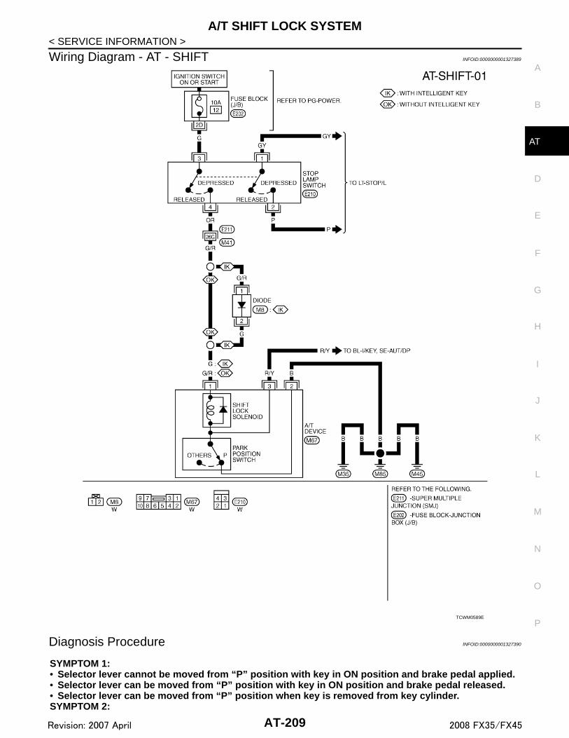
A/T SHIFT LOCK SYSTEM
D
E
F
G
H
I
J
K
L
M
A
B
T
N
O
P
< SERVICE INFORMATION >
A
Wiring Diagram - AT - SHIFT INFOID:0000000001327389
Diagnosis Procedure INFOID:0000000001327390
SYMPTOM 1:• Selector lever cannot be moved from “P” position with key in ON position and brake pedal applied.• Selector lever can be moved from “P” position with key in ON position and brake pedal released.• Selector lever can be moved from “P” position when key is removed from key cylinder.SYMPTOM 2:
TCWM0589E
AT-209Revision: 2007 April 2008 FX35/FX45

A/T SHIFT LOCK SYSTEM
< SERVICE INFORMATION >• Ignition key cannot be removed when selector lever is set to “P” position.• Ignition key can be removed when selector lever is set to any position except “P” position.1.CHECK KEY INTERLOCK CABLE
Check the key interlock cable for damage.OK or NGOK >> GO TO 2.NG >> Repair or replace key interlock cable. Refer to AT-212.
2.CHECK SELECTOR LEVER POSITION
Check the selector lever position for damage. Refer to AT-207, "Checking of A/T Position"OK or NGOK >> GO TO 3.NG >> Adjust A/T position. Refer to AT-207, "Adjustment of A/T Position".
3.CHECK SHIFT LOCK SOLENOID AND PARK POSITION SWITCH
1. Connect A/T device harness connector.2. Turn ignition switch ON.3. Selector lever is set in “P” position.4. Check operation.
OK or NGOK >> INSPECTION ENDNG >> GO TO 4.
4.CHECK POWER SOURCE
1. Turn ignition switch ON.2. Check the voltage between A/T device harness connector M67
terminal 1 and ground. Refer to AT-209, "Wiring Diagram - AT -SHIFT".
OK or NGOK >> GO TO 7.NG >> GO TO 5.
5.CHECK STOP LAMP SWITCH
1. Turn ignition switch OFF.2. Disconnect stop lamp switch harness connector.
Condition Brake pedal Operation
When ignition switch is turned to ON and selector lever is set in “P” position.
Depressed Yes
Released No
Condition Brake pedal Data (Approx.)
When ignition switch is turned to ON.
Depressed Battery voltage
Released 0 V
SCIA2122E
AT-210Revision: 2007 April 2008 FX35/FX45

A/T SHIFT LOCK SYSTEM
D
E
F
G
H
I
J
K
L
M
A
B
T
N
O
P
< SERVICE INFORMATION >
A
3. Check continuity between stop lamp switch harness connectorE210 terminals 3 and 4.
Check stop lamp switch after adjusting brake pedal — refer toBR-5.OK or NGOK >> GO TO 6.NG >> Repair or replace damaged parts.
6.DETECT MALFUNCTIONING ITEM
Check the following items. If any items are damaged, repair or replace damaged parts.• Harness for short or open between ignition switch and stop lamp switch harness connector E210 terminal 3.• Harness for short or open between stop lamp switch harness connector E210 terminal 4 and A/T device har-
ness connector M67 terminal 1.• 10 A fuse [No.12, located in the fuse block (J/B)].• Ignition switch, Refer to PG-3.OK or NGOK >> INSPECTION ENDNG >> Repair or replace damaged parts.
7.CHECK GROUND CIRCUIT
1. Turn ignition switch OFF.2. Disconnect A/T device harness connector.3. Check continuity between A/T device harness connector M67
terminal 2 and ground.
OK or NGOK >> Replace shift lock solenoid and park position switch
assembly.NG >> Repair open circuit in harness or connectors.
Condition Continuity
When brake pedal is depressed Yes
When brake pedal is released No
SCIA2126E
Continuity should exist.
SCIA2125E
AT-211Revision: 2007 April 2008 FX35/FX45
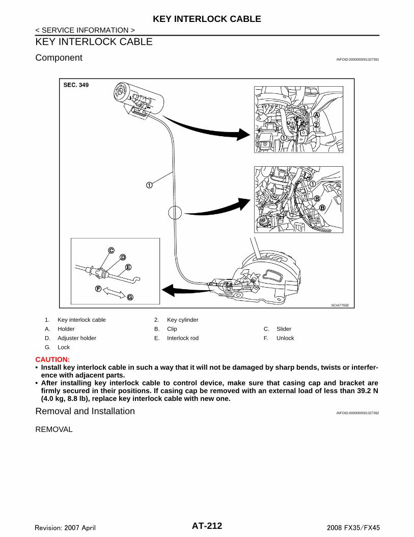
KEY INTERLOCK CABLE
< SERVICE INFORMATION >KEY INTERLOCK CABLE
Component INFOID:0000000001327391
CAUTION:• Install key interlock cable in such a way that it will not be damaged by sharp bends, twists or interfer-
ence with adjacent parts.• After installing key interlock cable to control device, make sure that casing cap and bracket are
firmly secured in their positions. If casing cap be removed with an external load of less than 39.2 N(4.0 kg, 8.8 lb), replace key interlock cable with new one.
Removal and Installation INFOID:0000000001327392
REMOVAL
1. Key interlock cable 2. Key cylinder
A. Holder B. Clip C. Slider
D. Adjuster holder E. Interlock rod F. Unlock
G. Lock
SCIA7755E
AT-212Revision: 2007 April 2008 FX35/FX45

KEY INTERLOCK CABLE
D
E
F
G
H
I
J
K
L
M
A
B
T
N
O
P
< SERVICE INFORMATION >
A
1. Unlock slider by squeezing lock tabs on slider from adjusterholder.
2. Remove casing cap from bracket of control device assemblyand remove interlock rod from adjuster holder.
3. Remove holder (A) from key cylinder (1) and remove key inter-lock cable (2).(B) : Clips
INSTALLATION1. Set key interlock cable (2) to key cylinder (1) and install holder
(A).2. Clamp key interlock cable (2) and fix to key interlock cable (2)
with clips (B).3. Turn ignition key to “LOCK” position.4. Set selector lever to “P” position.
SCIA1230E
SCIA7761E
SCIA7761E
AT-213Revision: 2007 April 2008 FX35/FX45

KEY INTERLOCK CABLE
< SERVICE INFORMATION >5. Insert interlock rod into adjuster holder.6. Install casing cap to bracket.7. Move slider in order to fix adjuster holder to interlock rod.
CAUTION:Do not touch adjacent parts of key interlock cable whenslider is being held.Insert slider into key interlock rod straightly.
SCIA1232E
AT-214Revision: 2007 April 2008 FX35/FX45

ON-VEHICLE SERVICE
D
E
F
G
H
I
J
K
L
M
A
B
T
N
O
P
< SERVICE INFORMATION >
A
ON-VEHICLE SERVICE
Control Valve with TCM and A/T Fluid Temperature Sensor 2 INFOID:0000000001327393
COMPONENTS
CONTROL VALVE WITH TCM ASSEMBLY REMOVAL AND INSTALLATION
Removal
1. Disconnect the battery cable from the negative terminal.2. Drain ATF through drain plug.3. Remove front cross bar. Refer to FSU-6, "Removal and Installation".4. Disconnect heated oxygen sensor 2 harness connector.5. Disconnect A/T assembly harness connector.
1. A/T 2. Snap ring 3. Sub-harness
4. Control valve with TCM 5. Bracket 6. A/T fluid temperature sensor 2
7. Oil pan gasket 8. Clip 9. Bracket (VK45DE)
10. Bracket (VK45DE) 11. Oil pan mounting bolt 12. Oil pan
13. Magnet 14. Drain plug 15. Drain plug gasket
16. Terminal cord assembly 17. O-ring
Refer to GI section to make sure icons (symbol marks) in the figure. Refer to GI-8, "Component".
SCIA8045E
AT-215Revision: 2007 April 2008 FX35/FX45

ON-VEHICLE SERVICE
< SERVICE INFORMATION >6. Remove snap ring from A/T assembly harness connector.7. Push A/T assembly harness connector.CAUTION:Be careful not to damage connector.
8. Remove bracket (1) (VK45DE), clips (2), oil pan (3) and oil pangasket.• : Vehicle front• : Bolt (22)• Drain plug (4)
9. Check foreign materials in oil pan to help determine causes ofmalfunction. If the ATF is very dark, smells burned, or containsforeign particles, the frictional material (clutches, band) mayneed replacement. A tacky film that will not wipe clean indicatesvarnish build up. Varnish can cause valves, servo, and clutchesto stick and can inhibit pump pressure.• If frictional material is detected, perform A/T fluid cooler
cleaning. Refer to AT-13, "A/T Fluid Cooler Cleaning".
10. Remove magnets from oil pan.
SCIA5021E
SCIA5022E
SCIA8128E
SCIA5199E
SCIA5200E
AT-216Revision: 2007 April 2008 FX35/FX45

ON-VEHICLE SERVICE
D
E
F
G
H
I
J
K
L
M
A
B
T
N
O
P
< SERVICE INFORMATION >
A
11. Disconnect A/T fluid temperature sensor 2 connector (1).CAUTION:Be careful not to damage connector.
12. Straighten terminal clips ( ) to free terminal cord assembly andA/T fluid temperature sensor 2 harness.
13. Disconnect revolution sensor connector.CAUTION:Be careful not to damage connector.
14. Straighten terminal clip to free revolution sensor harness.
15. Remove bolts A, B and C from control valve with TCM.• : Vehicle front
16. Remove control valve with TCM from transmission case.CAUTION:When removing, be careful with the manual valve notch andmanual plate height. Remove it vertically.
SCIA8069E
SCIA7524E
SCIA7525E
Bolt symbol Length mm (in) Number of bolts
A 42 (1.65) 5
B 55 (2.17) 6
C 40 (1.57) 1
SCIA8074E
SCIA5142E
AT-217Revision: 2007 April 2008 FX35/FX45

ON-VEHICLE SERVICE
< SERVICE INFORMATION >17. Remove A/T fluid temperature sensor 2 with bracket from con-trol valve with TCM.
18. Remove bracket from A/T fluid temperature sensor 2.
19. Remove O-ring from A/T assembly harness connector.
20. Disconnect TCM connectors.CAUTION:Be careful not to damage connectors.
SCIA5301E
SCIA5264E
SCIA5155E
SCIA5447E
AT-218Revision: 2007 April 2008 FX35/FX45

ON-VEHICLE SERVICE
D
E
F
G
H
I
J
K
L
M
A
B
T
N
O
P
< SERVICE INFORMATION >
A
21. Remove A/T assembly harness connector from control valvewith TCM using a flat-bladed screwdriver.
22. Disconnect TCM connector and park/neutral position switchconnector.CAUTION:Be careful not to damage connectors.
InstallationCAUTION:After completing installation, check A/T fluid leakage and A/F fluid level. Refer to AT-11, "Checking A/TFluid".1. Connect TCM connector and park/neutral position switch con-
nector.
2. Install A/T assembly harness connector from control valve withTCM.
SCIA5448E
SCIA5449E
SCIA5449E
SCIA5450E
AT-219Revision: 2007 April 2008 FX35/FX45

ON-VEHICLE SERVICE
< SERVICE INFORMATION >3. Connect TCM connectors.4. Install O-ring in A/T assembly harness connector.CAUTION:• Do not reuse O-ring.• Apply ATF to O-ring.
5. Install A/T fluid temperature sensor 2 to bracket.
6. Install A/T fluid temperature sensor 2 (with bracket) in controlvalve with TCM, and then tighten A/T fluid temperature sensor 2mounting bolt to the specified torque. Refer to "COMPO-NENTS".CAUTION:Adjust bolt hole of bracket to bolt hole of control valve withTCM.
7. Install control valve with TCM in transmission case.CAUTION:• Make sure that turbine revolution sensor securely installs
turbine revolution sensor hole.• Hang down revolution sensor harness toward outside so
as not to disturb installation of control valve with TCM.• Adjust A/T assembly harness connector of control valve
with TCM to terminal hole of transmission case.
SCIA5447E
SCIA5155E
SCIA5264E
SCIA5301E
SCIA5034E
AT-220Revision: 2007 April 2008 FX35/FX45

ON-VEHICLE SERVICE
D
E
F
G
H
I
J
K
L
M
A
B
T
N
O
P
< SERVICE INFORMATION >
A
• Assemble it so that manual valve cutout is engaged withmanual plate projection.
8. Install bolts A, B and C in control valve with TCM.• : Vehicle front
9. Tighten bolt 1, 2 and 3 temporarily to prevent dislocation. Afterthat tighten them in order (1 → 2 → 3), and then tighten otherbolts to the specified torque. Refer to "COMPONENTS".• : Vehicle front
10. Connect A/T fluid temperature sensor 2 connector (1).11. Securely fasten terminal cord assembly and A/T fluid tempera-
ture sensor 2 harness with terminal clips ( ).
SCIA5142E
Bolt symbol Length mm (in) Number of bolts
A 42 (1.65) 5
B 55 (2.17) 6
C 40 (1.57) 1
SCIA8074E
SCIA8075E
SCIA8069E
AT-221Revision: 2007 April 2008 FX35/FX45

ON-VEHICLE SERVICE
< SERVICE INFORMATION >12. Connect revolution sensor connector.13. Securely fasten revolution sensor harness with terminal clip.
14. Install magnets in oil pan.
15. Install oil pan to transmission case.a. Install oil pan gasket to oil pan.
CAUTION:• Do not reuse oil pan gasket.• Install it in the direction to align hole positions.• Completely remove all moisture, oil and old gasket, etc. from oil pan gasket mounting surface.
b. Install oil pan (3) (with oil pan gasket), clips (2) and brackets (1)(VK45DE) to transmission case.• : Vehicle front • : Bolt (22)CAUTION:• Install it so that drain plug (4) comes to the position as
shown in the figure.• Be careful not to pinch harnesses.• Completely remove all moisture, oil and old gasket, etc.
from oil pan mounting surface.
SCIA7524E
SCIA7525E
SCIA5200E
SCIA8128E
AT-222Revision: 2007 April 2008 FX35/FX45

ON-VEHICLE SERVICE
D
E
F
G
H
I
J
K
L
M
A
B
T
N
O
P
< SERVICE INFORMATION >
A
c. Tighten oil pan mounting bolts to the specified torque in numeri-cal order shown in the figure after temporarily tightening them.Refer to "COMPONENTS".CAUTION:Do not reuse oil pan mounting bolts.
16. Install drain plug to oil pan, and then tighten drain plug to thespecified torque. Refer to "COMPONENTS".CAUTION:Do not reuse drain plug gasket.
17. Pull up A/T assembly harness connector.CAUTION:Be careful not to damage connector.
18. Install snap ring to A/T assembly harness connector.19. Connect A/T assembly harness connector.20. Connect heated oxygen sensor 2 harness connector.21. Install front cross bar. Refer to FSU-6, "Removal and Installa-
tion".22. Pour ATF into A/T assembly. Refer to AT-11, "Changing A/T
Fluid".23. Connect the battery cable to the negative terminal.
A/T FLUID TEMPERATURE SENSOR 2 REMOVAL AND INSTALLATION
Removal
1. Disconnect the battery cable from the negative terminal.2. Remove front cross bar. Refer to FSU-6, "Removal and Installation".3. Disconnect heated oxygen sensor 2 harness connector.4. Drain ATF through drain plug.5. Remove bracket (1) (VK45DE), clips (2), oil pan (3) and oil pan
gasket.• : Vehicle front• : Bolt (22)• Drain plug (4)
SCIA4113E
SCIA5038E
SCIA5039E
SCIA8128E
AT-223Revision: 2007 April 2008 FX35/FX45

ON-VEHICLE SERVICE
< SERVICE INFORMATION >6. Check foreign materials in oil pan to help determine causes ofmalfunction. If the ATF is very dark, smells burned, or containsforeign particles, the frictional material (clutches, band) mayneed replacement. A tacky film that will not wipe clean indicatesvarnish build up. Varnish can cause valves, servo, and clutchesto stick and can inhibit pump pressure.• If frictional material is detected, perform A/T fluid cooler
cleaning. Refer to AT-13, "A/T Fluid Cooler Cleaning".
7. Disconnect A/T fluid temperature sensor 2 connector (1).CAUTION:Be careful not to damage connector.
8. Straighten terminal clip ( ) to free A/T fluid temperature sensor2 harness.
9. Remove A/T fluid temperature sensor 2 with bracket from con-trol valve with TCM.
10. Remove bracket from A/T fluid temperature sensor 2.
InstallationCAUTION:After completing installation, check A/T fluid leakage and A/F fluid level. Refer to AT-11, "Checking A/TFluid".
SCIA5199E
SCIA8076E
SCIA5302E
SCIA5264E
AT-224Revision: 2007 April 2008 FX35/FX45

ON-VEHICLE SERVICE
D
E
F
G
H
I
J
K
L
M
A
B
T
N
O
P
< SERVICE INFORMATION >
A
1. Install A/T fluid temperature sensor 2 to bracket.
2. Install A/T fluid temperature sensor 2 (with bracket) in controlvalve with TCM, and then tighten A/T fluid temperature sensor 2mounting bolt to the specified torque. Refer to "COMPO-NENTS".
3. Connect A/T fluid temperature sensor 2 connector (1).4. Securely fasten A/T fluid temperature sensor 2 harness with ter-
minal clip ( ).
5. Install oil pan to transmission case.a. Install oil pan gasket to oil pan.
CAUTION:• Do not reuse oil pan gasket.• Install it in the direction to align hole positions.• Completely remove all moisture, oil and old gasket, etc. from oil pan mounting surface.
b. Install oil pan (3) (with oil pan gasket), clips (2) and brackets (1)(VK45DE) to transmission case.• : Vehicle front• : Bolt (22)CAUTION:• Install it so that drain plug (4) comes to the position as
shown in the figure.• Be careful not to pinch harnesses.• Completely remove all moisture, oil and old gasket, etc.
from oil pan mounting surface.
SCIA5264E
SCIA5302E
SCIA8076E
SCIA8128E
AT-225Revision: 2007 April 2008 FX35/FX45

ON-VEHICLE SERVICE
< SERVICE INFORMATION >c. Tighten oil pan mounting bolts to the specified torque in numeri-cal order shown in the figure after temporarily tightening them.Refer to "COMPONENTS".CAUTION:Do not reuse oil pan mounting bolts.
6. Install drain plug to oil pan, and then tighten drain plug to thespecified torque. Refer to "COMPONENTS".CAUTION:Do not reuse drain plug gasket.
7. Connect heated oxygen sensor 2 harness connector.8. Install front cross bar. Refer to FSU-6, "Removal and Installa-
tion".9. Pour ATF into A/T assembly. Refer to AT-11, "Changing A/T Fluid".10. Connect the battery cable to the negative terminal.
Parking Component (2WD Models Only) INFOID:0000000001327394
COMPONENTS
REMOVAL
SCIA4113E
1. Rear oil seal 2. Rear extension 3. Parking actuator support
4. Parking pawl 5. Return spring 6. Pawl shaft
7. Self-sealing bolt 8. Seal ring 9. Parking gear
10. Output shaft 11. Bearing race 12. Needle bearing
Refer to GI section to make sure icons (symbol marks) in the figure. Refer to GI-8, "Component".
However, refer to the following symbol for others.
* : Apply Genuine Anaerobic Liquid Gasket or equivalent. Refer to GI-44, "Recommended Chemical Product and Sealant".
SCIA7433E
AT-226Revision: 2007 April 2008 FX35/FX45

ON-VEHICLE SERVICE
D
E
F
G
H
I
J
K
L
M
A
B
T
N
O
P
< SERVICE INFORMATION >
A
1. Drain ATF through drain plug.2. Remove exhaust front tube and center muffler with power tool. Refer to EX-3, "Component".3. Remove rear propeller shaft. Refer to PR-9, "Removal and Installation".4. Remove control rod. Refer to AT-206, "Control Rod Removal and Installation".5. Support A/T assembly with a transmission jack.
CAUTION:When setting transmission jack, be careful not to allow it to collide against the drain plug.
6. Remove rear engine mounting member with power tool. Refer to AT-241, "Removal and Installation (2WDModels)".
7. Remove engine mounting insulator (rear). Refer to AT-241, "Removal and Installation (2WD Models)".8. Remove tightening bolts for rear extension assembly and trans-
mission case.
9. Tap rear extension assembly with soft hammer.
10. Remove rear extension assembly from transmission case. (Withneedle bearing.)
11. Remove bearing race from output shaft.
SCIA6941E
SCIA3432E
SCIA3431E
SCIA5245E
AT-227Revision: 2007 April 2008 FX35/FX45

ON-VEHICLE SERVICE
< SERVICE INFORMATION >12. Remove output shaft from transmission case by rotating left/right.
13. Remove parking gear from output shaft.
14. Remove seal rings from output shaft.
15. Remove needle bearing from rear extension.
16. Remove parking actuator support from rear extension.
SCIA5246E
SCIA5247E
SCIA5209E
SCIA6021E
SCIA3423E
AT-228Revision: 2007 April 2008 FX35/FX45

ON-VEHICLE SERVICE
D
E
F
G
H
I
J
K
L
M
A
B
T
N
O
P
< SERVICE INFORMATION >
A
17. Remove parking pawl (with return spring) and pawl shaft fromrear extension.
18. Remove return spring from parking pawl.
19. Remove rear oil seal from rear extension.CAUTION:Be careful not to scratch rear extension.
INSPECTION• If the contact surface on parking actuator support, parking pawl,
etc. has excessive wear, abrasion, bend, or any other damage,replace the components.
SCIA3424E
SCIA2445E
SCIA3524E
SCIA5143E
AT-229Revision: 2007 April 2008 FX35/FX45

ON-VEHICLE SERVICE
< SERVICE INFORMATION >INSTALLATIONCAUTION:After completing installation, check A/T position, A/T fluid leakage and A/F fluid level. Refer to AT-207,"Checking of A/T Position", AT-11, "Checking A/T Fluid".1. As shown in the figure, use a drift to drive rear oil seal into the
rear extension until it is flush.CAUTION:• Do not reuse rear oil seal.• Apply ATF to rear oil seal.
2. Install return spring to parking pawl.
3. Install parking pawl (with return spring) and pawl shaft to rearextension.
SCIA5144E
SCIA5311E
SCIA2445E
SCIA3424E
AT-230Revision: 2007 April 2008 FX35/FX45

ON-VEHICLE SERVICE
D
E
F
G
H
I
J
K
L
M
A
B
T
N
O
P
< SERVICE INFORMATION >
A
4. Install parking actuator support to rear extension.
5. Install needle bearing to rear extension.CAUTION:• Take care with the direction of needle bearing. Refer to
AT-264, "Location of Adjusting Shims, Needle Bearings,Thrust Washers and Snap Rings".
• Apply petroleum jelly to needle bearing.
6. Install seal rings in output shaft.CAUTION:• Do not reuse seal rings.• Apply petroleum jelly to seal rings.
7. Install parking gear to output shaft
8. Install output shaft to transmission case.
SCIA3423E
SCIA6021E
SCIA5209E
SCIA5247E
SCIA5246E
AT-231Revision: 2007 April 2008 FX35/FX45
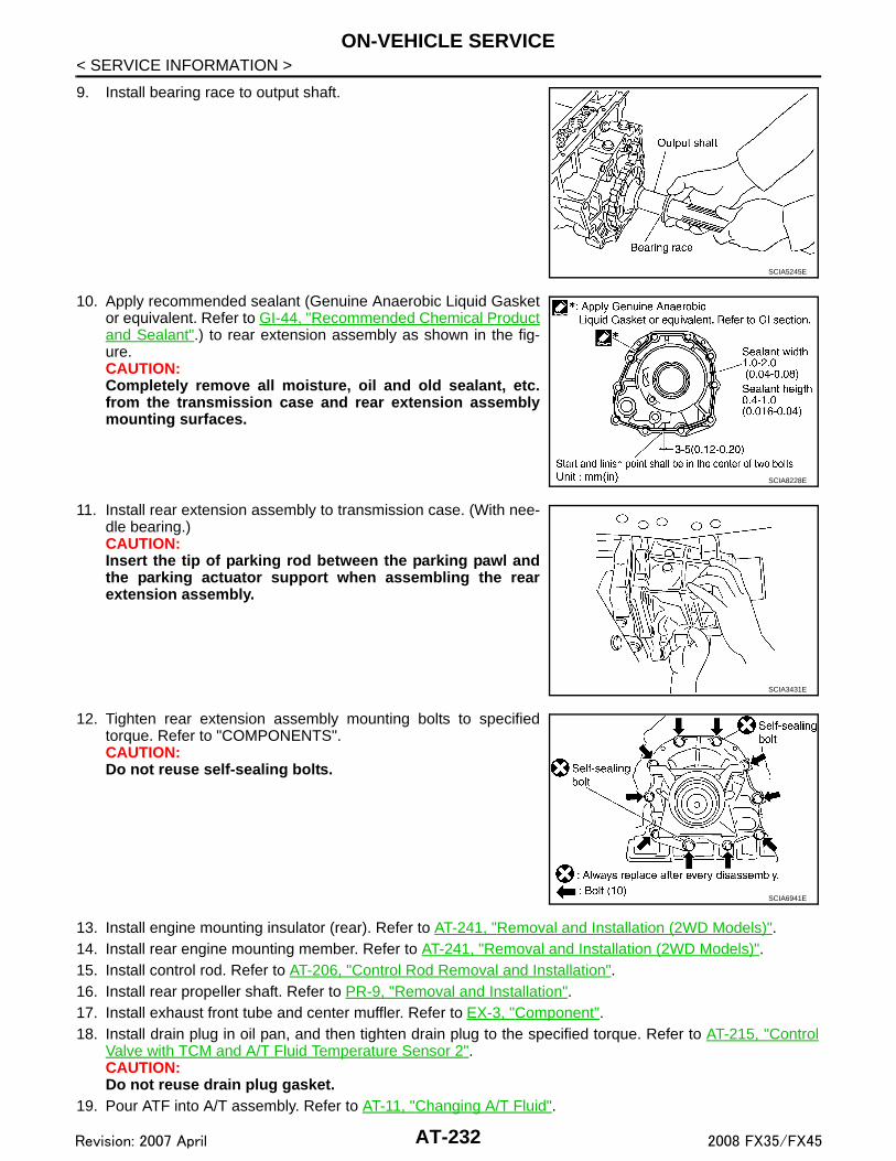
ON-VEHICLE SERVICE
< SERVICE INFORMATION >9. Install bearing race to output shaft.
10. Apply recommended sealant (Genuine Anaerobic Liquid Gasketor equivalent. Refer to GI-44, "Recommended Chemical Productand Sealant".) to rear extension assembly as shown in the fig-ure.CAUTION:Completely remove all moisture, oil and old sealant, etc.from the transmission case and rear extension assemblymounting surfaces.
11. Install rear extension assembly to transmission case. (With nee-dle bearing.)CAUTION:Insert the tip of parking rod between the parking pawl andthe parking actuator support when assembling the rearextension assembly.
12. Tighten rear extension assembly mounting bolts to specifiedtorque. Refer to "COMPONENTS".CAUTION:Do not reuse self-sealing bolts.
13. Install engine mounting insulator (rear). Refer to AT-241, "Removal and Installation (2WD Models)".14. Install rear engine mounting member. Refer to AT-241, "Removal and Installation (2WD Models)".15. Install control rod. Refer to AT-206, "Control Rod Removal and Installation".16. Install rear propeller shaft. Refer to PR-9, "Removal and Installation".17. Install exhaust front tube and center muffler. Refer to EX-3, "Component".18. Install drain plug in oil pan, and then tighten drain plug to the specified torque. Refer to AT-215, "Control
Valve with TCM and A/T Fluid Temperature Sensor 2".CAUTION:Do not reuse drain plug gasket.
19. Pour ATF into A/T assembly. Refer to AT-11, "Changing A/T Fluid".
SCIA5245E
SCIA8228E
SCIA3431E
SCIA6941E
AT-232Revision: 2007 April 2008 FX35/FX45

ON-VEHICLE SERVICE
D
E
F
G
H
I
J
K
L
M
A
B
T
N
O
P
< SERVICE INFORMATION >
A
Rear Oil Seal INFOID:0000000001327395
REMOVAL1. Remove center muffler with power tool. Refer to EX-3, "Compo-
nent".2. Remove rear propeller shaft. Refer to PR-9, "Removal and
Installation".3. Remove front propeller shaft (AWD models). Refer to PR-4,
"Removal and Installation".4. Remove transfer assembly from A/T assembly (AWD models).
Refer to TF-40, "Removal and Installation".5. Remove rear oil seal using a flat-bladed screwdriver.
CAUTION:Be careful not to scratch rear extension assembly (2WDmodels) or adapter case assembly (AWD models).
INSTALLATIONCAUTION:After completing installation, check A/T fluid leakage and A/T fluid level. Refer to AT-11, "Checking A/TFluid".1. As shown in the figure, use the drift to drive rear oil seal into rear
extension assembly (2WD models) or adapter case assembly(AWD models) until it is flush.CAUTION:• Do not reuse rear oil seal.• Apply ATF to rear oil seal.
2. Install transfer assembly to A/T assembly (AWD models). Referto TF-40, "Removal and Installation".
3. Install front propeller shaft (AWD models). Refer to PR-4,"Removal and Installation".
4. Install rear propeller shaft. Refer to PR-9, "Removal and Installa-tion".
5. Install center muffler. Refer to EX-3, "Component".
Revolution Sensor Component (2WD Models Only) INFOID:0000000001327396
COMPONENTS
SCIA5410E
SCIA5411E
AT-233Revision: 2007 April 2008 FX35/FX45

ON-VEHICLE SERVICE
< SERVICE INFORMATION >REMOVAL1. Disconnect the battery cable from the negative terminal.2. Drain ATF through drain plug.3. Remove front cross bar. Refer to FSU-6, "Removal and Installation".4. Remove exhaust front tube and center muffler with power tool. Refer to EX-3, "Component".5. Remove rear propeller shaft. Refer to PR-9, "Removal and Installation".6. Remove control rod. Refer to AT-206, "Control Rod Removal and Installation".7. Remove clips (1), oil pan (2) and oil pan gasket.
• : Vehicle front• : Bolt (22)• Drain plug (3)
1. Rear extension 2. A/T 3. Oil pan gasket
4. Clip 5. Oil pan mounting bolt 6. Oil pan
7. Drain plug 8. Drain plug gasket 9. Revolution sensor
10. Self-sealing bolt
Refer to GI section to make sure icons (symbol marks) in the figure. Refer to GI-8, "Component".
However, refer to the following symbol for others.
* : Apply Genuine Anaerobic Liquid Gasket or equivalent. Refer to GI-44, "Recommended Chemical Product and Sealant"
SCIA8043E
SCIA8117E
AT-234Revision: 2007 April 2008 FX35/FX45

ON-VEHICLE SERVICE
D
E
F
G
H
I
J
K
L
M
A
B
T
N
O
P
< SERVICE INFORMATION >
A
8. Check foreign materials in oil pan to help determine causes ofmalfunction. If the ATF is very dark, smells burned, or containsforeign particles, the frictional material (clutches, band) mayneed replacement. A tacky film that will not wipe clean indicatesvarnish build up. Varnish can cause valves, servo, and clutchesto stick and can inhibit pump pressure.• If frictional material is detected, perform A/T fluid cooler
cleaning. Refer to AT-13, "A/T Fluid Cooler Cleaning".9. Support A/T assembly with a transmission jack.
CAUTION:When setting transmission jack, place wooden blocks toprevent from damaging control valve with TCM and trans-mission case.
10. Remove rear engine mounting member with power tool. Refer to AT-241, "Removal and Installation (2WDModels)".
11. Remove tightening bolts for rear extension assembly and trans-mission case.
12. Tap rear extension assembly with soft hammer.
13. Remove rear extension assembly from transmission case. (Withneedle bearing.)
SCIA5199E
SCIA6941E
SCIA3432E
SCIA3431E
AT-235Revision: 2007 April 2008 FX35/FX45

ON-VEHICLE SERVICE
< SERVICE INFORMATION >14. Disconnect revolution sensor connector.CAUTION:Be careful not to damage connector
15. Straighten terminal clip to free revolution sensor harness.
16. Remove revolution sensor from transmission case.CAUTION:• Do not subject it to impact by dropping or hitting it.• Do not disassemble.• Do not allow metal filings, etc. to get on the sensor's front
edge magnetic area.• Do not place in an area affected by magnetism.
INSTALLATIONCAUTION:After completing installation, check A/T position, A/T fluid leakage and A/F fluid level. Refer to AT-207,"Checking of A/T Position", AT-11, "Checking A/T Fluid".1. Install revolution sensor in transmission case, and then tighten
revolution sensor mounting bolt to the specified torque. Refer to"COMPONENTS".CAUTION:• Do not subject it to impact by dropping or hitting it.• Do not disassemble.• Do not allow metal filings, etc. to get on the sensor's front
edge magnetic area.• Do not place in an area affected by magnetism.
SCIA7524E
SCIA7525E
SCIA3997E
SCIA3997E
AT-236Revision: 2007 April 2008 FX35/FX45

ON-VEHICLE SERVICE
D
E
F
G
H
I
J
K
L
M
A
B
T
N
O
P
< SERVICE INFORMATION >
A
2. Connect revolution sensor connector.
3. Securely fasten revolution sensor harness with clip.
4. Apply recommended sealant (Genuine Anaerobic Liquid Gasketor equivalent. Refer to GI-44, "Recommended Chemical Productand Sealant".) to rear extension assembly as shown in the fig-ure.CAUTION:Completely remove all moisture, oil and old sealant, etc.from transmission case and rear extension assemblymounting surfaces.
5. Install rear extension assembly to transmission case. (With nee-dle bearing.)CAUTION:Insert the tip of parking rod between the parking pole andthe parking actuator support when assembling the rearextension assembly.
6. Tighten rear extension assembly mounting bolts to specifiedtorque. Refer to "COMPONENTS".CAUTION:Do not reuse self-sealing bolts.
7. Install rear engine mounting member. Refer to AT-241,"Removal and Installation (2WD Models)".
8. Install oil pan to transmission case.a. Install oil pan gasket to oil pan.
CAUTION:• Do not reuse oil pan gasket.• Install it in the direction to align hole positions.
SCIA7524E
SCIA7525E
SCIA8228E
SCIA3431E
SCIA6941E
AT-237Revision: 2007 April 2008 FX35/FX45

ON-VEHICLE SERVICE
< SERVICE INFORMATION >• Completely remove all moisture, oil and old gasket, etc. from oil pan mounting surface.b. Install oil pan (2) (with oil pan gasket) and clips (1) to transmis-
sion case.• : Vehicle front• : Bolt (22)CAUTION:• Install it so that drain plug (3) comes to the position as
shown in the figure.• Be careful not to pinch harnesses.• Completely remove all moisture, oil and old gasket, etc.
from oil pan mounting surface.
c. Tighten oil pan mounting bolts to the specified torque in numeri-cal order shown in the figure after temporarily tightening them.Refer to "COMPONENTS".CAUTION:Do not reuse oil pan mounting bolts.
9. Install drain plug to oil pan, and then tighten drain plug to thespecified torque. Refer to "COMPONENTS".CAUTION:Do not reuse drain plug gasket.
10. Install control rod. Refer to AT-206, "Control Rod Removal andInstallation".
11. Install rear propeller shaft. Refer to PR-9, "Removal and Installa-tion".
12. Install exhaust front tube and center muffler. Refer to EX-3, "Component".13. Install front cross bar. Refer to FSU-6, "Removal and Installation".14. Pour ATF into A/T assembly. Refer to AT-11, "Changing A/T Fluid".15. Connect the battery cable to the negative terminal.
SCIA8117E
SCIA4113E
AT-238Revision: 2007 April 2008 FX35/FX45

AIR BREATHER HOSE
D
E
F
G
H
I
J
K
L
M
A
B
T
N
O
P
< SERVICE INFORMATION >
A
AIR BREATHER HOSE
Removal and Installation INFOID:0000000001327397
VQ35DE ENGINE MODELRefer to the figure below for air breather hose removal and installation procedure.
CAUTION:• When installing an air breather hose, be careful not to be crushed or blocked by folding or bending
the hose.• When inserting a hose to the transmission tube, be sure to insert it fully until its end reaches the
tube bend R portion.
VK45DE ENGINE MODEL
SCIA2151E
AT-239Revision: 2007 April 2008 FX35/FX45

AIR BREATHER HOSE
< SERVICE INFORMATION >Refer to the figure below for air breather hose removal and installation procedure.CAUTION:• When installing an air breather hose, be careful not to be crushed or blocked by folding or bending
the hose.• When inserting a hose to the transmission tube, be sure to insert it fully until its end reaches the
tube bend R portion.
SCIA2152E
AT-240Revision: 2007 April 2008 FX35/FX45

TRANSMISSION ASSEMBLY
D
E
F
G
H
I
J
K
L
M
A
B
T
N
O
P
< SERVICE INFORMATION >
A
TRANSMISSION ASSEMBLY
Removal and Installation (2WD Models) INFOID:0000000001327398
COMPONENTS
REMOVALCAUTION:• When removing the A/T assembly from engine, first remove the crankshaft position sensor (POS)
from the A/T assembly.• Be careful not to damage sensor edge.1. Disconnect the battery cable from the negative terminal.2. Remove engine cover.3. Remove A/T fluid level gauge.4. Remove engine under cover with power tool.5. Remove front cross bar. Refer to FSU-6, "Removal and Installation"6. Remove exhaust front tube and center muffler with power tool. Refer to EX-3, "Component".7. Remove three way catalyst. Refer to EM-26, "Removal and Installation".8. Remove rear propeller shaft. Refer to PR-9, "Removal and Installation".9. Remove control rod. Refer to AT-206, "Control Rod Removal and Installation".
1. A/T fluid charging pipe 2. O-ring 3. Engine mounting insulator (rear)
4. Rear engine mounting member 5. Copper washer 6. Fluid cooler tube
7. Bracket 8. A/T assembly 9. A/T fluid level gauge
SCIA6379E
AT-241Revision: 2007 April 2008 FX35/FX45

TRANSMISSION ASSEMBLY
< SERVICE INFORMATION >10. Remove crankshaft position sensor (POS) from A/T assembly.CAUTION:• Do not subject it to impact by dropping or hitting it.• Do not disassemble.• Do not allow metal filings, etc. to get on the sensor's front
edge magnetic area.• Do not place in an area affected by magnetism.
11. Remove starter motor. Refer to SC-14, "Removal and Installa-tion [VQ35DE Engine Models (2WD)]".
12. Remove fluid cooler tube.13. Remove rear plate cover. Refer to EM-30, "Removal and Instal-
lation (2WD Models)".14. Remove rear cover plate. Refer to EM-30, "Removal and Installation (2WD Models)".15. Turn crankshaft, and remove the four tightening bolts for drive
plate and torque converter.CAUTION:When turning crankshaft, turn it clockwise as viewed fromthe front of the engine.
16. Support A/T assembly with a transmission jack.CAUTION:When setting the transmission jack, be careful not to allowit to collide against the drain plug.
17. Remove rear engine mounting member with power tool.18. Remove engine mounting insulator (rear).19. Remove air breather hose. Refer to AT-239, "Removal and Installation".20. Disconnect A/T assembly harness connector.21. Remove A/T fluid charging pipe from A/T assembly.22. Remove O-ring from A/T fluid charging pipe.23. Plug up openings such as the A/T fluid charging pipe hole, etc.24. Remove bolts fixing A/T assembly to engine assembly with power tool.25. Remove A/T assembly from vehicle with a transmission jack.
• Secure torque converter to prevent it from dropping.• Secure A/T assembly to a transmission jack.
INSPECTION
Installation and Inspection of Torque Converter• After inserting a torque converter to a A/T, be sure to check dis-
tance “A” to ensure it is within the reference value limit.
SCIA2155E
SCIA2288E
SCIA0499E
Distance “A” : 25.0 mm (0.98 in) or more
SAT017B
AT-242Revision: 2007 April 2008 FX35/FX45

TRANSMISSION ASSEMBLY
D
E
F
G
H
I
J
K
L
M
A
B
T
N
O
P
< SERVICE INFORMATION >
A
INSTALLATIONInstall the removed parts in the reverse order of the removal, while paying attention to the following work.• When installing A/T assembly to the engine assembly, attach the
fixing bolts in accordance with the following standard.
• Align the positions of tightening bolts for drive plate with those ofthe torque converter, and temporarily tighten the bolts. Then,tighten the bolts with the specified torque. Refer to "COMPO-NENTS".
CAUTION:• Do not reuse O-ring and copper washers.• When turning crankshaft, turn it clockwise as viewed from the
front of the engine.• When tightening the tightening bolts for the torque converter
after fixing the crankshaft pulley bolts, be sure to confirm thetightening torque of the crankshaft pulley mounting bolts.Refer to EM-65, "Removal and Installation".
• After converter is installed to drive plate, rotate crankshaft several turns and check to be sure thattransmission rotates freely without binding.
• Install crankshaft position sensor (POS). Refer to EM-30, "Removal and Installation (2WD Models)".• After completing installation, check A/T fluid leakage, A/T fluid level, and the A/T positions of A/T. Refer to
AT-11, "Checking A/T Fluid", AT-207, "Checking of A/T Position".
Removal and Installation (AWD Models) INFOID:0000000001327399
COMPONENTS (FOR VQ35DE)
Bolt No. 1 2 3 4
Number of bolts 1 5 2 2
Bolt length
“ ”mm (in)55 (2.17) 65 (2.56) 65 (2.56) 35 (1.38)
Tightening torqueN·m (kg-m, ft-lb)
75(7.7, 55)
55(5.6, 41)
47(4.8, 35)
SCIA3949E
SCIA2288E
AT-243Revision: 2007 April 2008 FX35/FX45
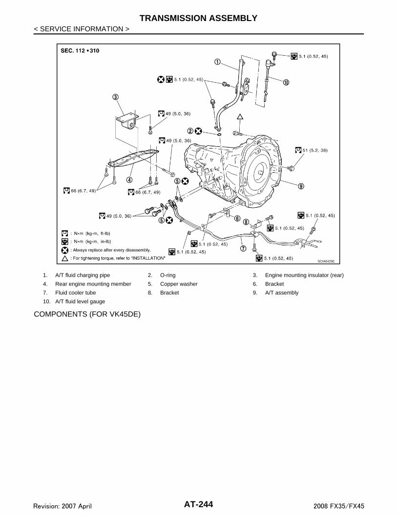
TRANSMISSION ASSEMBLY
< SERVICE INFORMATION >COMPONENTS (FOR VK45DE)
1. A/T fluid charging pipe 2. O-ring 3. Engine mounting insulator (rear)
4. Rear engine mounting member 5. Copper washer 6. Bracket
7. Fluid cooler tube 8. Bracket 9. A/T assembly
10. A/T fluid level gauge
SCIA6425E
AT-244Revision: 2007 April 2008 FX35/FX45

TRANSMISSION ASSEMBLY
D
E
F
G
H
I
J
K
L
M
A
B
T
N
O
P
< SERVICE INFORMATION >
A
REMOVALCAUTION:• When removing the A/T assembly from engine, first remove the crankshaft position sensor (POS)
from the A/T assembly.• Be careful not to damage sensor edge.1. Disconnect the battery cable from the negative terminal.2. Remove engine cover.3. Remove A/T fluid level gauge.4. Remove engine under cover with power tool.5. Remove front cross bar. Refer to FSU-6, "Removal and Installation".6. Remove exhaust front tube and center muffler with power tool. Refer to EX-3, "Component".7. Remove three way catalyst. Refer to EM-179, "Removal and Installation".8. Remove front propeller shaft. Refer to PR-4, "Removal and Installation".9. Remove rear propeller shaft. Refer to PR-9, "Removal and Installation".10. Remove control rod. Refer to AT-206, "Control Rod Removal and Installation".
1. A/T fluid charging pipe 2. O-ring 3. Engine mounting insulator (rear)
4. Rear engine mounting member 5. Copper washer 6. Bracket
7. Fluid cooler tube 8. Bracket 9. Bracket
10. Bracket 11. A/T assembly 12. A/T fluid level gauge
SCIA6426E
AT-245Revision: 2007 April 2008 FX35/FX45

TRANSMISSION ASSEMBLY
< SERVICE INFORMATION >11. Remove crankshaft position sensor (POS) from A/T assembly.CAUTION:• Do not subject it to impact by dropping or hitting it.• Do not disassemble.• Do not allow metal filings, etc., to get on the sensor's front
edge magnetic area.• Do not place in an area affected by magnetism.
12. Remove starter motor. Refer to SC-15, "Removal and Installa-tion [VQ35DE Engine Models (AWD)]" (for VQ35DE) or SC-13,"Removal and Installation (VK45DE Engine Models)" (forVK45DE).
13. Disconnect fluid cooler tube from A/T assembly.
14. Remove rear plate cover. Refer to EM-36, "Removal and Instal-lation (AWD Models)" (for VQ35DE) or EM-183, "Removal andInstallation" (for VK45DE).
15. Turn crankshaft, and remove the four tightening bolts for driveplate and torque converter.CAUTION:When turning crankshaft, turn it clockwise as viewed fromthe front of the engine.
16. Remove dynamic damper (for VQ35DE). Refer to EM-117,"Removal and Installation (AWD Models)".
17. Support A/T assembly with a transmission jack.CAUTION:When setting the transmission jack, be careful not to allowit to collide against the drain plug.
18. Remove rear engine mounting member with power tool.19. Remove engine mounting insulator (rear).20. Tilt the A/T assembly slightly to keep the clearance between
body and A/T assembly, and then disconnect air breather hosefrom A/T fluid charging pipe. Refer to AT-239, "Removal andInstallation".
21. Disconnect A/T assembly harness connector and transfer assembly harness connector.22. Remove A/T fluid charging pipe.23. Remove O-ring from A/T fluid charging pipe.24. Plug up openings such as the A/T fluid charging pipe hole, etc.25. Remove bolts fixing transmission assembly to engine with power tool.
SCIA2011E
SCIA5326E
SCIA2010E
SCIA2202E
AT-246Revision: 2007 April 2008 FX35/FX45

TRANSMISSION ASSEMBLY
D
E
F
G
H
I
J
K
L
M
A
B
T
N
O
P
< SERVICE INFORMATION >
A
26. Remove A/T assembly with transfer from vehicle.• Secure torque converter to prevent it from dropping.• Secure A/T assembly to a jack.
27. Remove transfer from A/T assembly. Refer to TF-40, "Removaland Installation".
INSPECTION
Installation and Inspection of Torque Converter• After inserting a torque converter to a A/T, be sure to check dis-
tance “A” to ensure it is within the reference value limit.
INSTALLATIONInstall the removed parts in the reverse order of the removal, while paying attention to the following work.• When installing A/T assembly to the engine assembly, attach the fixing bolts in accordance with the following
standard.For VQ35DE models
For VK45DE models
*1 : No.2 bolt also secures A/T fluid charging pipe and washer.
*2 : No.4 bolt also secures bracket.
(A) : A/T to engine
SCIA2203E
Distance “A”VQ35DE models : 25.0 mm (0.98 in) or moreVK45DE models : 22.0 mm (0.87 in) or more
SAT017B
Bolt No. 1 2 3 4
Number of bolts 1 5 2 1
Bolt length
“ ”mm (in)55 (2.17) 65 (2.56) 35 (1.38) 40 (1.57)
Tightening torqueN·m (kg-m, ft-lb)
75(7.7, 55)
47(4.8, 35)
34(3.5, 25)
SCIA4600E
Bolt No. 1 2*1 3 4*2
Number of bolts 4 1 4 1
Bolt length mm (in) 70 (2.76) 70 (2.76) 65 (2.56) 70 (2.76)
Tightening torqueN·m (kg-m, ft-lb)
113(12, 83)
74.0(7.5, 55)
113(12,83)
SCIA7756E
AT-247Revision: 2007 April 2008 FX35/FX45

TRANSMISSION ASSEMBLY
< SERVICE INFORMATION >• Align the positions of tightening bolts for drive plate with those ofthe torque converter, and temporarily tighten the bolts. Then,tighten the bolts with the specified torque. Refer to "COMPO-NENTS (FOR VQ35DE)" or "COMPONENTS (FOR VK45DE)".
CAUTION:• Do not reuse O-ring and copper washers.• When turning crankshaft, turn it clockwise as viewed from the
front of the engine.• When tightening the tightening bolts for the torque converter
after fixing the crankshaft pulley bolts, be sure to confirm thetightening torque of the crankshaft pulley mounting bolts.Refer to EM-65, "Removal and Installation" (for VQ35DE) orEM-200, "Removal and Installation" (for VK45DE)
• After converter is installed to drive plate, rotate crankshaft several turns and check to be sure thattransmission rotates freely without binding.
• Install crankshaft position sensor (POS). Refer to EM-35, "Component (AWD Models)" (for VQ35DE) or EM-183, "Component" (for VK45DE).
• After completing installation, check A/T fluid leakage, A/T fluid level, and the positions of A/T. Refer to AT-11,"Checking A/T Fluid", AT-207, "Checking of A/T Position".
SCIA2010E
AT-248Revision: 2007 April 2008 FX35/FX45

OVERHAUL
D
E
F
G
H
I
J
K
L
M
A
B
T
N
O
P
< SERVICE INFORMATION >
A
OVERHAUL
Component INFOID:0000000001327400
VQ35DE models
SCIA8098E
1. O-ring 2. Oil pump cover 3. O-ring
4. Oil pump housing 5. Self-sealing bolt 6. Torque converter
7. Converter housing 8. Oil pump housing oil seal 9. Bearing race
AT-249Revision: 2007 April 2008 FX35/FX45

OVERHAUL
< SERVICE INFORMATION >10. Needle bearing 11. O-ring 12. Front carrier assembly
13. Snap ring 14. Front sun gear 15. 3rd one-way clutch
16. Snap ring 17. Bearing race 18. Needle bearing
19. Seal ring 20. Input clutch assembly 21. Needle bearing
22. Rear internal gear 23. Brake band 24. Mid carrier assembly
25. Needle bearing 26. Bearing race 27. Rear carrier assembly
28. Needle bearing 29. Mid sun gear 30. Seal ring
31. Rear sun gear 32. 1st one-way clutch 33. Snap ring
34. Needle bearing 35. High and low reverse clutch hub 36. Snap ring
37. Bearing race 38. Needle bearing
Refer to GI section to make sure icons (symbol marks) in the figure. Refer to GI-8, "Component".
However, refer to the following symbol for others.
: Apply Genuine RTV silicone sealant or equivalent. Refer to GI-44, "Recommended Chemical Product and Sealant".
AT-250Revision: 2007 April 2008 FX35/FX45

OVERHAUL
D
E
F
G
H
I
J
K
L
M
A
B
T
N
O
P
< SERVICE INFORMATION >
A
VK45DE models
SCIA7984E
1. O-ring 2. Oil pump cover 3. O-ring
4. Oil pump housing 5. Self-sealing bolt 6. Torque converter
7. Converter housing 8. Oil pump housing oil seal 9. Bearing race
10. Needle bearing 11. O-ring 12. Front carrier assembly
13. Needle bearing 14. Snap ring 15. Front sun gear
16. 3rd one-way clutch 17. Snap ring 18. Bearing race
19. Needle bearing 20. Seal ring 21. Input clutch assembly
AT-251Revision: 2007 April 2008 FX35/FX45

OVERHAUL
< SERVICE INFORMATION >22. Needle bearing 23. Rear internal gear 24. Brake band
25. Mid carrier assembly 26. Needle bearing 27. Bearing race
28. Rear carrier assembly 29. Needle bearing 30. Mid sun gear
31. Seal ring 32. Rear sun gear 33. 1st one-way clutch
34. Snap ring 35. Needle bearing 36. High and low reverse clutch hub
37. Snap ring 38. Bearing race 39. Needle bearing
Refer to GI section to make sure icons (symbol marks) in the figure. Refer to GI-8, "Component".
However, refer to the following symbols for others.
: Apply Genuine RTV silicone sealant or equivalent. Refer to GI-44, "Recommended Chemical Product and Sealant".
AT-252Revision: 2007 April 2008 FX35/FX45
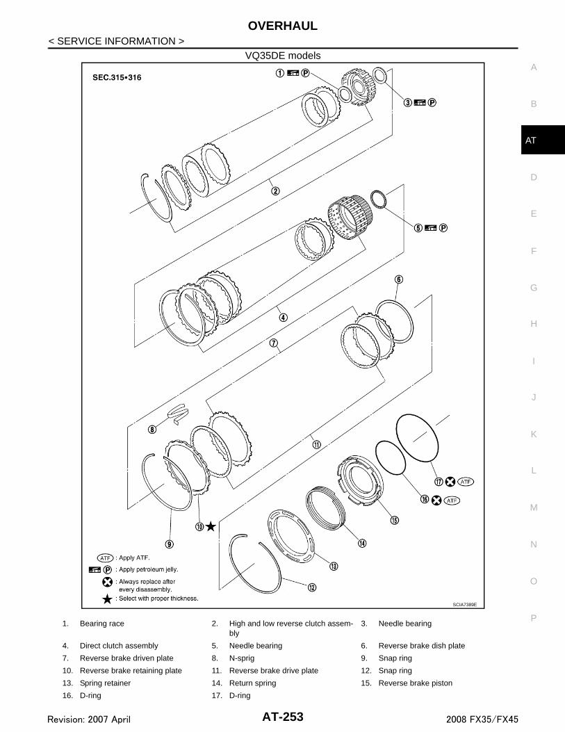
OVERHAUL
D
E
F
G
H
I
J
K
L
M
A
B
T
N
O
P
< SERVICE INFORMATION >
A
VQ35DE models
SCIA7389E
1. Bearing race 2. High and low reverse clutch assem-bly
3. Needle bearing
4. Direct clutch assembly 5. Needle bearing 6. Reverse brake dish plate
7. Reverse brake driven plate 8. N-sprig 9. Snap ring
10. Reverse brake retaining plate 11. Reverse brake drive plate 12. Snap ring
13. Spring retainer 14. Return spring 15. Reverse brake piston
16. D-ring 17. D-ring
AT-253Revision: 2007 April 2008 FX35/FX45

OVERHAUL
< SERVICE INFORMATION >VK45DE models
SCIA6982E
1. Bearing race 2. High and low reverse clutch assembly 3. Needle bearing
4. Direct clutch assembly 5. Needle bearing 6. Reverse brake dish plate
7. Reverse brake dish plate 8. Reverse brake driven plate 9. N-spring
10. Snap ring 11. Reverse brake retaining plate 12. Reverse brake drive plate
13. Snap ring 14. Spring retainer 15. Return spring
16. Reverse brake piston 17. D-ring 18. D-ring
Refer to GI section to make sure icons (symbol marks) in the figure. Refer to GI-8, "Component".
AT-254Revision: 2007 April 2008 FX35/FX45

OVERHAUL
D
E
F
G
H
I
J
K
L
M
A
B
T
N
O
P
< SERVICE INFORMATION >
A
2WD models
SCIA8099E
1. Rear oil seal 2. Self-sealing bolt 3. Rear extension
4. Parking actuator support 5. Return spring 6. Parking pawl
7. Pawl shaft 8. Seal ring 9. Needle bearing
10. Revolution sensor 11. Parking gear 12. Output shaft
13. Bearing race 14. Needle bearing 15. Manual plate
16. Parking rod 17. Manual shaft oil seal 18. Manual shaft
19. O-ring 20. Band servo anchor end pin 21. Detent spring
AT-255Revision: 2007 April 2008 FX35/FX45

OVERHAUL
< SERVICE INFORMATION >22. Spacer 23. Seal ring 24. Snap ring
25. Return spring 26. O-ring 27. Servo assembly
28. Snap ring 29. Sub-harness 30. Control valve with TCM
31. Bracket 32. A/T fluid temperature sensor 2 33. Clip
34. Oil pan mounting bolt 35. Oil pan 36. Magnet
37. Drain plug 38. Drain plug gasket 39. Oil pan gasket
40. Terminal cord assembly 41. O-ring 42. Retaining pin
43. Transmission case
Refer to GI section to make sure icons (symbol marks) in the figure. Refer to GI-8, "Component".
However, refer to the following symbol for others.
* : Apply Genuine Anaerobic Liquid Gasket or equivalent. Refer to GI-44, "Recommended Chemical Product and Sealant".
AT-256Revision: 2007 April 2008 FX35/FX45

OVERHAUL
D
E
F
G
H
I
J
K
L
M
A
B
T
N
O
P
< SERVICE INFORMATION >
A
VQ35DE models for AWD
SCIA8100E
1. Rear oil seal 2. Bracket 3. Adapter case
4. Parking actuator support 5. Return spring 6. Parking pawl
7. Pawl shaft 8. Self-sealing bolt 9. Seal ring
10. Needle bearing 11. Gasket 12. Revolution sensor
13. Parking gear 14. Output shaft 15. Bearing race
16. Needle bearing 17. Manual plate 18. Parking rod
19. Manual shaft oil seal 20. Manual shaft 21. O-ring
AT-257Revision: 2007 April 2008 FX35/FX45

OVERHAUL
< SERVICE INFORMATION >22. Band servo anchor end pin 23. Detent spring 24. Spacer
25. Seal ring 26. Snap ring 27. Return spring
28. O-ring 29. Servo assembly 30. Snap ring
31. Sub-harness 32. Control valve with TCM 33. Bracket
34. A/T fluid temperature sensor 2 35. Clip 36. Oil pan mounting bolt
37. Oil pan 38. Magnet 39. Drain plug
40. Drain plug gasket 41. Oil pan gasket 42. Terminal cord assembly
43. O-ring 44. Retaining pin 45. Transmission case
Refer to GI section to make sure icons (symbol marks) in the figure. Refer to GI-8, "Component".
AT-258Revision: 2007 April 2008 FX35/FX45

OVERHAUL
D
E
F
G
H
I
J
K
L
M
A
B
T
N
O
P
< SERVICE INFORMATION >
A
VK45DE models for 4WD
SCIA8101E
1. Rear oil seal 2. Self-sealing bolt 3. Bracket
4. Adapter case 5. Parking actuator support 6. Parking pawl
7. Return spring 8. Pawl shaft 9. Seal ring
10. Needle bearing 11. Gasket 12. Revolution sensor
13. Parking gear 14. Output shaft 15. Bearing race
16. Needle bearing 17. Manual plate 18. Parking rod
19. Manual shaft oil seal 20. Manual shaft 21. O-ring
AT-259Revision: 2007 April 2008 FX35/FX45

OVERHAUL
< SERVICE INFORMATION >22. Band servo anchor end pin 23. Detent spring 24. Spacer
25. Seal ring 26. Snap ring 27. Return spring
28. O-ring 29. Servo assembly 30. Snap ring
31. Sub-harness 32. Control valve with TCM 33. Bracket
34. A/T fluid temperature sensor 2 35. Clip 36. Bracket
37. Bracket 38. Oil pan mounting bolt 39. Oil pan
40. Magnet 41. Drain plug 42. Drain plug gasket
43. Oil pan gasket 44. Terminal cord assembly 45. O-ring
46. Retaining pin 47. Transmission case
Refer to GI section to make sure icons (symbol marks) in the figure. Refer to GI-8, "Component".
AT-260Revision: 2007 April 2008 FX35/FX45

OVERHAUL
D
E
F
G
H
I
J
K
L
M
A
B
T
N
O
P
< SERVICE INFORMATION >
A
Oil Channel INFOID:0000000001327401
2WD models
SCIA6387E
AT-261Revision: 2007 April 2008 FX35/FX45

OVERHAUL
< SERVICE INFORMATION >VQ35DE models for AWD
SCIA6487E
AT-262Revision: 2007 April 2008 FX35/FX45

OVERHAUL
D
E
F
G
H
I
J
K
L
M
A
B
T
N
O
P
< SERVICE INFORMATION >
A
VK45DE models for AWD
SCIA5189E
AT-263Revision: 2007 April 2008 FX35/FX45

OVERHAUL
< SERVICE INFORMATION >Location of Adjusting Shims, Needle Bearings, Thrust Washers and Snap RingsINFOID:0000000001327402
2WD models
SCIA6535E
AT-264Revision: 2007 April 2008 FX35/FX45

OVERHAUL
D
E
F
G
H
I
J
K
L
M
A
B
T
N
O
P
< SERVICE INFORMATION >
A
VQ35DE models for AWD
SCIA6488E
AT-265Revision: 2007 April 2008 FX35/FX45

OVERHAUL
< SERVICE INFORMATION >VK45DE models for AWD
SCIA7223E
AT-266Revision: 2007 April 2008 FX35/FX45

DISASSEMBLY
D
E
F
G
H
I
J
K
L
M
A
B
T
N
O
P
< SERVICE INFORMATION >
A
DISASSEMBLY
Disassembly INFOID:0000000001327403
CAUTION:Do not disassemble parts behind drum support. Refer to AT-16, "Cross-Sectional View (2WD Models)",AT-17, "Cross-Sectional View (VQ35DE Models for AWD)" or AT-18, "Cross-Sectional View (VK45DEModels for AWD)".1. Drain ATF through drain plug.2. Remove torque converter by holding it firmly and turning while
pulling straight out.
3. Check torque converter one-way clutch using check tool asshown in the figure.
a. Insert check tool into the groove of bearing support built intoone-way clutch outer race.
b. When fixing bearing support with check tool, rotate one-wayclutch spline using screwdriver.
c. Make sure that inner race rotates clockwise only. If not, replacetorque converter assembly.
4. Remove tightening bolts (1) for converter housing and transmis-sion case.• : Bolt (8)• Self-sealing bolts (2)
5. Remove converter housing from transmission case.CAUTION:Be careful not to scratch converter housing.
SCIA5010E
SCIA3171E
SCIA7985E
AT-267Revision: 2007 April 2008 FX35/FX45

DISASSEMBLY
< SERVICE INFORMATION >6. Remove O-ring from input clutch assembly.7. Remove tightening bolts for oil pump assembly and transmis-sion case.
8. Attach the sliding hammers to oil pump assembly and extract itevenly from transmission case.CAUTION:• Fully tighten sliding hammer screw.• Make sure that bearing race is installed to the oil pump
assembly edge surface.
9. Remove O-ring from oil pump assembly.
SCIA5011E
SCIA2300E
SCIA5474E
SCIA5172E
AT-268Revision: 2007 April 2008 FX35/FX45

DISASSEMBLY
D
E
F
G
H
I
J
K
L
M
A
B
T
N
O
P
< SERVICE INFORMATION >
A
10. Remove bearing race from oil pump assembly.
11. Remove needle bearing from front sun gear.
12. Remove front sun gear assembly from front carrier assembly.NOTE:Remove front sun gear by rotating left/right.
13. Remove seal rings from input clutch assembly.
14. Remove front carrier assembly from rear carrier assembly. (Withinput clutch assembly and rear internal gear.)CAUTION:Be careful to remove it with needle bearing.
SCIA5252E
SCIA2808E
SCIA5014E
SCIA2470E
SCIA5015E
AT-269Revision: 2007 April 2008 FX35/FX45

DISASSEMBLY
< SERVICE INFORMATION >15. Loosen lock nut and remove band servo anchor end pin fromtransmission case.
16. Remove brake band from transmission case.
• To prevent brake linings from cracking or peeling, do notstretch the flexible band unnecessarily. When removingthe brake band, always secure it with a clip as shown inthe figure at right.Leave the clip in position after removing the brake band.
• Check brake band facing for damage, cracks, wear orburns.
17. Remove mid carrier assembly and rear carrier assembly as aunit.
18. Remove mid carrier assembly from rear carrier assembly.
SCIA6512E
SCIA2580E
SAT655
SCIA5017E
SCIA5697E
AT-270Revision: 2007 April 2008 FX35/FX45
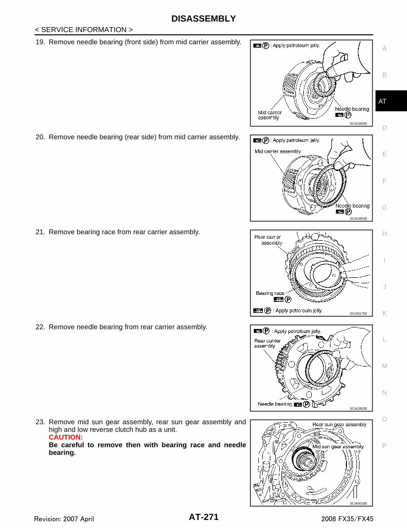
DISASSEMBLY
D
E
F
G
H
I
J
K
L
M
A
B
T
N
O
P
< SERVICE INFORMATION >
A
19. Remove needle bearing (front side) from mid carrier assembly.
20. Remove needle bearing (rear side) from mid carrier assembly.
21. Remove bearing race from rear carrier assembly.
22. Remove needle bearing from rear carrier assembly.
23. Remove mid sun gear assembly, rear sun gear assembly andhigh and low reverse clutch hub as a unit.CAUTION:Be careful to remove then with bearing race and needlebearing.
SCIA2805E
SCIA2804E
SCIA5175E
SCIA2803E
SCIA5018E
AT-271Revision: 2007 April 2008 FX35/FX45

DISASSEMBLY
< SERVICE INFORMATION >24. Remove high and low reverse clutch assembly from direct clutchassembly.CAUTION:Make sure that needle bearing is installed to the high andlow reverse clutch assembly edge surface.
25. Remove direct clutch assembly from reverse brake.
26. Remove needle bearing from drum support.
27. Remove snap ring from A/T assembly harness connector.
28. Push A/T assembly harness connector.CAUTION:Be careful not to damage connector.
SCIA2306E
SCIA5019E
SCIA5198E
SCIA5021E
SCIA5022E
AT-272Revision: 2007 April 2008 FX35/FX45

DISASSEMBLY
D
E
F
G
H
I
J
K
L
M
A
B
T
N
O
P
< SERVICE INFORMATION >
A
29. Remove bracket (1) (VK45DE), clips (2), oil pan (3) and oil pangasket.• : Vehicle front• : Bolt (22)• Drain plug (4)
30. Check foreign materials in oil pan to help determine causes ofmalfunction. If the ATF is very dark, smells burned, or containsforeign particles, the frictional material (clutches, band) mayneed replacement. A tacky film that will not wipe clean indicatesvarnish build up. Varnish can cause valves, servo, and clutchesto stick and can inhibit pump pressure.• If frictional material is detected, perform A/T fluid cooler
cleaning. Refer to AT-13, "A/T Fluid Cooler Cleaning".
31. Remove magnets from oil pan.
32. Disconnect A/T fluid temperature sensor 2 connector (1).CAUTION:Be careful not to damage connector.
33. Straighten terminal clips ( ) to free terminal cord assembly andA/T fluid temperature sensor 2 harness.
34. Disconnect revolution sensor connector.CAUTION:Be careful not to damage connector.
SCIA8128E
SCIA5199E
SCIA5200E
SCIA8069E
SCIA7524E
AT-273Revision: 2007 April 2008 FX35/FX45

DISASSEMBLY
< SERVICE INFORMATION >35. Straighten terminal clip to free revolution sensor harness.
36. Remove bolts A, B and C from control valve with TCM.• : Front
37. Remove control valve with TCM from transmission case.CAUTION:When removing, be careful with the manual valve notch andmanual plate height. Remove it vertically.
38. Remove A/T fluid temperature sensor 2 with bracket from con-trol valve with TCM.
39. Remove bracket from A/T fluid temperature sensor 2.
SCIA7526E
Bolt symbol Length mm (in) Number of bolts
A 42 (1.65) 5
B 55 (2.17) 6
C 40 (1.57) 1
SCIA8077E
SCIA5260E
SCIA5301E
SCIA5264E
AT-274Revision: 2007 April 2008 FX35/FX45

DISASSEMBLY
D
E
F
G
H
I
J
K
L
M
A
B
T
N
O
P
< SERVICE INFORMATION >
A
40. Remove O-ring from A/T assembly harness connector.
41. Disconnect TCM connectors.CAUTION:Be careful not to damage connectors.
42. Remove A/T assembly harness connector from control valvewith TCM using a flat-bladed screwdriver.
43. Disconnect TCM connector and park/neutral position switchconnector.CAUTION:Be careful not to damage connectors.
44. Remove rear extension assembly (2WD models) or adapter case assembly (AWD models) according tothe following procedures.
a. 2WD models
SCIA5155E
SCIA5447E
SCIA5448E
SCIA5449E
AT-275Revision: 2007 April 2008 FX35/FX45

DISASSEMBLY
< SERVICE INFORMATION >i. Remove tightening bolts for rear extension assembly and trans-mission case.
ii. Tap rear extension assembly with soft hammer.
iii. Remove rear extension assembly from transmission case. (Withneedle bearing.)
b. AWD modelsi. Remove tightening bolts (1) for adapter case assembly and
transmission case. [With bracket (2).]: Bolt (10)
• Self-sealing bolts (3)
SCIA6941E
SCIA5028E
SCIA5029E
SCIA7210E
AT-276Revision: 2007 April 2008 FX35/FX45

DISASSEMBLY
D
E
F
G
H
I
J
K
L
M
A
B
T
N
O
P
< SERVICE INFORMATION >
A
ii. Tap adapter case assembly with soft hammer.
iii. Remove adapter case assembly from transmission case. (Withneedle bearing)
iv. Remove gasket from transmission case.
45. Remove bearing race from output shaft.
46. Remove output shaft from transmission case by rotating left/right.
SCIA5201E
SCIA5186E
SCIA5231E
SCIA5245E
SCIA5030E
AT-277Revision: 2007 April 2008 FX35/FX45

DISASSEMBLY
< SERVICE INFORMATION >47. Remove parking gear from output shaft.
48. Remove seal rings from output shaft.
49. Remove needle bearing from transmission case.
50. Remove revolution sensor from transmission case.CAUTION:• Do not subject it to impact by dropping or hitting it.• Do not disassemble.• Do not allow metal filings, etc. to get on the sensor's front
edge magnetic area.• Do not place in an area affected by magnetism.
51. Remove reverse brake snap ring (fixing plate) using 2 flat-bladed screwdrivers.NOTE:Press out snap ring from the transmission case oil pan side gapusing a flat-bladed screwdriver, and remove it using anotherscrewdriver.
52. Remove reverse brake retaining plate from transmission case.• Check facing for burns, cracks or damage. If necessary,
replace the plate.
SCIA5247E
SCIA5209E
SCIA5031E
SCIA2320E
SCIA5032E
AT-278Revision: 2007 April 2008 FX35/FX45

DISASSEMBLY
D
E
F
G
H
I
J
K
L
M
A
B
T
N
O
P
< SERVICE INFORMATION >
A
53. Remove N-spring from transmission case.
54. Remove reverse brake drive plates, driven plates and dish platefrom transmission case.• Check facing for burns, cracks or damage. If necessary,
replace the plate.
55. Remove snap ring (fixing spring retainer) using a flat-bladedscrewdriver.
56. Remove spring retainer and return spring from transmissioncase.
57. Remove seal rings from drum support.
SCIA5214E
SCIA2322E
SCIA2323E
SCIA2324E
SCIA3333E
AT-279Revision: 2007 April 2008 FX35/FX45
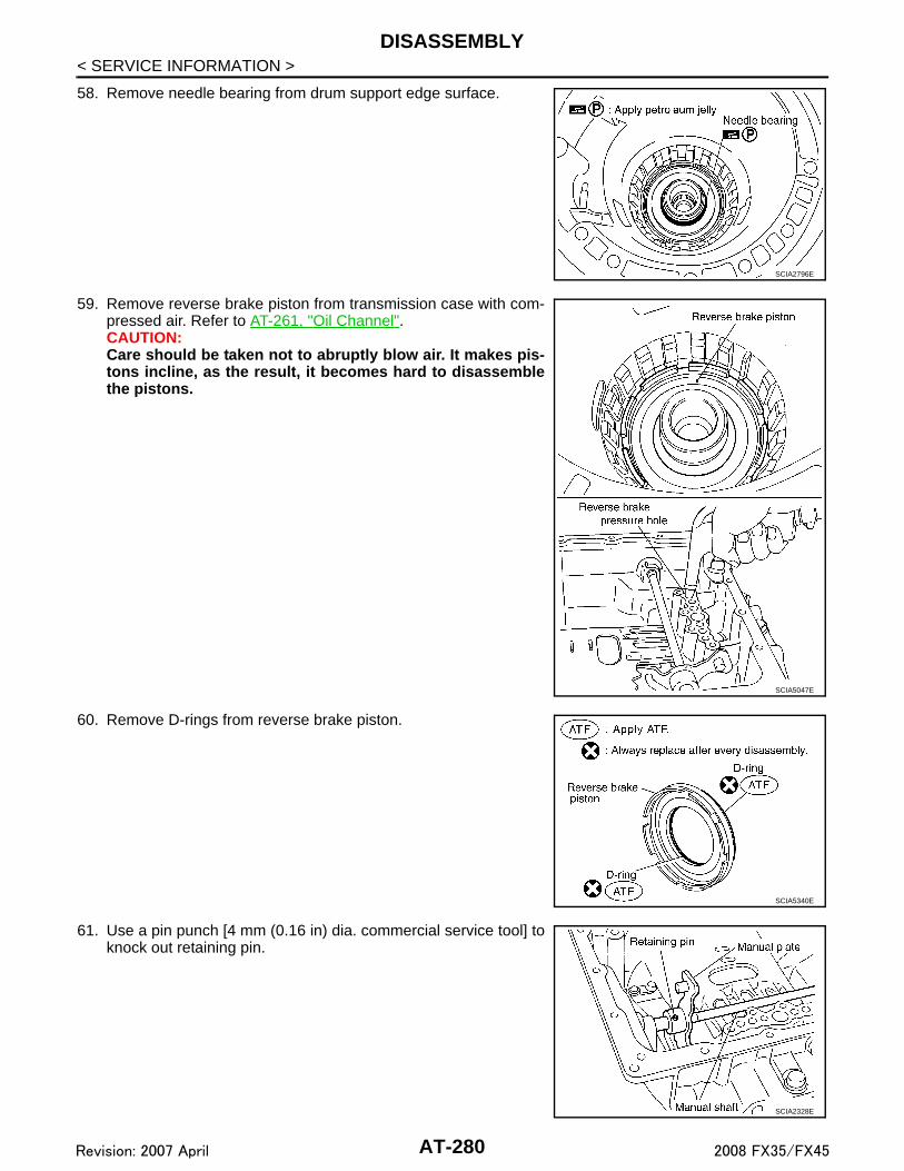
DISASSEMBLY
< SERVICE INFORMATION >58. Remove needle bearing from drum support edge surface.
59. Remove reverse brake piston from transmission case with com-pressed air. Refer to AT-261, "Oil Channel".CAUTION:Care should be taken not to abruptly blow air. It makes pis-tons incline, as the result, it becomes hard to disassemblethe pistons.
60. Remove D-rings from reverse brake piston.
61. Use a pin punch [4 mm (0.16 in) dia. commercial service tool] toknock out retaining pin.
SCIA2796E
SCIA5047E
SCIA5340E
SCIA2328E
AT-280Revision: 2007 April 2008 FX35/FX45

DISASSEMBLY
D
E
F
G
H
I
J
K
L
M
A
B
T
N
O
P
< SERVICE INFORMATION >
A
62. Remove manual shaft retaining pin with pair of nippers.
63. Remove manual plate (with parking rod) from manual shaft.
64. Remove parking rod from manual plate.
65. Remove manual shaft from transmission case.
66. Remove manual shaft oil seals using a flat-bladed screwdriver.CAUTION:Be careful not to scratch transmission case.
SCIA2329E
SCIA5715E
SCIA5220E
SCIA5716E
SCIA2331E
AT-281Revision: 2007 April 2008 FX35/FX45

DISASSEMBLY
< SERVICE INFORMATION >67. Remove detent spring and spacer from transmission case.
68. Using pair of snap ring pliers, remove snap ring from transmis-sion case.
69. Remove servo assembly (with return spring) from transmissioncase.
70. Remove return spring from servo assembly.
71. Remove O-rings from servo assembly.
SCIA5248E
SCIA2333E
SCIA5679E
SCIA5717E
SCIA5719E
AT-282Revision: 2007 April 2008 FX35/FX45

DISASSEMBLY
D
E
F
G
H
I
J
K
L
M
A
B
T
N
O
P
< SERVICE INFORMATION >
A
72. Remove needle bearing from rear extension (2WD models) oradapter case (AWD models).
73. Remove parking actuator support from rear extension (2WDmodels) or adapter case (AWD models).
74. Remove parking pawl (with return spring) and pawl shaft fromrear extension (2WD models) or adapter case (AWD models).
75. Remove return spring from parking pawl.• VQ35DE models
SCIA5221E
SCIA3423E
SCIA3424E
SCIA2445E
AT-283Revision: 2007 April 2008 FX35/FX45

DISASSEMBLY
< SERVICE INFORMATION >• VK45DE models- Return spring (1)- Parking pawl (2)
76. Remove rear oil seal from rear extension (2WD models) oradapter case (AWD models).CAUTION:Be careful not to scratch rear extension (2WD models) oradapter case (AWD models).
SCIA6180J
SCIA5481E
AT-284Revision: 2007 April 2008 FX35/FX45

REPAIR FOR COMPONENT PARTS
D
E
F
G
H
I
J
K
L
M
A
B
T
N
O
P
< SERVICE INFORMATION >
A
REPAIR FOR COMPONENT PARTS
Oil Pump INFOID:0000000001327404
COMPONENTS
DISASSEMBLY1. Remove oil pump housing from oil pump cover.
2. Remove oil pump housing oil seal using a flat-bladed screw-driver.CAUTION:Be careful not to scratch oil pump housing.
1. O-ring 2. Oil pump cover 3. O-ring
4. Oil pump housing 5. Oil pump housing oil seal
SCIA5227E
SCIA5228E
SCIA2840E
AT-285Revision: 2007 April 2008 FX35/FX45

REPAIR FOR COMPONENT PARTS
< SERVICE INFORMATION >3. Remove O-ring from oil pump housing.4. Remove O-ring from oil pump cover.
ASSEMBLY1. Install O-ring to oil pump cover.
CAUTION:• Do not reuse O-ring.• Apply ATF to O-ring.
2. Install O-ring to oil pump housing.CAUTION:• Do not reuse O-ring.• Apply ATF to O-ring.
SCIA2841E
SCIA5230E
SCIA5230E
SCIA2841E
AT-286Revision: 2007 April 2008 FX35/FX45

REPAIR FOR COMPONENT PARTS
D
E
F
G
H
I
J
K
L
M
A
B
T
N
O
P
< SERVICE INFORMATION >
A
3. Using the drift, install oil pump housing oil seal to the oil pumphousing until it is flush.CAUTION:• Do not reuse oil pump housing oil seal.• Apply ATF to oil pump housing oil seal.
4. Install oil pump housing to oil pump cover.5. Tighten bolts to the specified torque in numerical order shown in
the figure after temporarily tightening them. Refer to "COMPO-NENTS".
Front Sun Gear, 3rd One-Way Clutch INFOID:0000000001327405
COMPONENTS
DISASSEMBLY
SCIA5313E
SCIA6388E
1. Front sun gear 2. 3rd one-way clutch 3. Snap ring
SCIA3114E
AT-287Revision: 2007 April 2008 FX35/FX45

REPAIR FOR COMPONENT PARTS
< SERVICE INFORMATION >1. Using a flat-bladed screwdriver, remove snap ring from front sungear.
2. Remove 3rd one-way clutch from front sun gear.
INSPECTION
3rd One-way Clutch• Check frictional surface for wear or damage.
CAUTION:If necessary, replace the 3rd one-way clutch.
Front Sun Gear Snap Ring• Check for deformation, fatigue or damage.
CAUTION:If necessary, replace the snap ring.
Front Sun Gear• Check for deformation, fatigue or damage.
CAUTION:If necessary, replace the front sun gear.
ASSEMBLY1. Install 3rd one-way clutch in front sun gear.
CAUTION:Apply ATF to 3rd one-way clutch.
SCIA3110E
SCIA3111E
SCIA3111E
AT-288Revision: 2007 April 2008 FX35/FX45

REPAIR FOR COMPONENT PARTS
D
E
F
G
H
I
J
K
L
M
A
B
T
N
O
P
< SERVICE INFORMATION >
A
2. Using a flat-bladed screwdriver, install snap ring in front sungear.
3. Check operation of 3rd one-way clutch.a. Hold oil pump assembly and turn front sun gear.b. Check 3rd one-way clutch for correct locking and unlocking
directions.CAUTION:If not as shown in the figure, check installation direction of3rd one-way clutch.
Front Carrier, Input Clutch, Rear Internal Gear INFOID:0000000001327406
COMPONENTS
SCIA3110E
SCIA3131E
AT-289Revision: 2007 April 2008 FX35/FX45

REPAIR FOR COMPONENT PARTS
< SERVICE INFORMATION >VQ35DE models
SCIA5426E
1. Seal ring 2. O-ring 3. Needle bearing
4. Bearing race 5. Front carrier assembly 6. Snap ring
7. Snap ring 8. Retaining plate 9. Driven plate
10. Input clutch drum 11. Drive plate 12. Rear internal gear
AT-290Revision: 2007 April 2008 FX35/FX45

REPAIR FOR COMPONENT PARTS
D
E
F
G
H
I
J
K
L
M
A
B
T
N
O
P
< SERVICE INFORMATION >
A
VK45DE models
DISASSEMBLY
SCIA7070E
1. Seal ring 2. O-ring 3. Needle bearing
4. Bearing race 5. Front carrier assembly 6. Needle bearing
7. Snap ring 8. Snap ring 9. Retaining plate
10. Driven plate 11. Input clutch drum 12. Drive plate
13. Rear internal gear
Refer to GI section to make sure icons (symbol marks) in the figure. Refer to GI-8, "Component".
AT-291Revision: 2007 April 2008 FX35/FX45

REPAIR FOR COMPONENT PARTS
< SERVICE INFORMATION >1. Compress snap ring using 2 flat-bladed screwdrivers.2. Remove front carrier assembly and input clutch assembly fromrear internal gear.3. Remove front carrier assembly from input clutch assembly.
a. Remove bearing race from front carrier assembly.
b. Remove needle bearing from front carrier assembly. (VK45DEmodels)
c. Remove snap ring from front carrier assembly.CAUTION:Do not expand snap ring excessively.
4. Disassemble input clutch assembly.a. Remove O-ring and seal rings from input clutch assembly.
SCIA5339E
SCIA2847E
SCIA5233E
SCIA5476E
SCIA5235E
AT-292Revision: 2007 April 2008 FX35/FX45

REPAIR FOR COMPONENT PARTS
D
E
F
G
H
I
J
K
L
M
A
B
T
N
O
P
< SERVICE INFORMATION >
A
b. Remove needle bearing from input clutch assembly.
c. Using a flat-bladed screwdriver, remove snap ring from inputclutch drum.
d. Remove drive plates, driven plates and retaining plate from inputclutch drum.
INSPECTION
Front Carrier Snap Ring• Check for deformation, fatigue or damage.
CAUTION:If necessary, replace the snap ring.
Input Clutch Snap Ring• Check for deformation, fatigue or damage.
CAUTION:If necessary, replace the input clutch assembly.
Input Clutch Drum• Check for deformation, fatigue or damage or burns.
CAUTION:If necessary, replace the input clutch assembly.
Input Clutch Drive Plates• Check facing for burns, cracks or damage.
CAUTION:If necessary, replace the input clutch assembly.
Input Clutch Retaining Plates and Driven Plates• Check facing for burns, cracks or damage.
CAUTION:If necessary, replace the input clutch assembly.
Front Carrier• Check for deformation, fatigue or damage.
CAUTION:If necessary, replace the front carrier assembly.
Rear Internal Gear• Check for deformation, fatigue or damage.
CAUTION:If necessary, replace the rear internal gear assembly.
ASSEMBLY1. Install input clutch.
SCIA2853E
SCIA2864E
AT-293Revision: 2007 April 2008 FX35/FX45

REPAIR FOR COMPONENT PARTS
< SERVICE INFORMATION >a. Install drive plates, driven plates and retaining plate in inputclutch drum.• Snap ring (1)• Retaining plate (2)• Drive plate (3)• Driven plate (4)• Drive plate/Driven plate: 7/7CAUTION:Take care with order of plates.
b. Using a flat-bladed screwdriver, install snap ring in input clutchdrum.
c. Install needle bearing in input clutch assembly.CAUTION:• Take care with the direction of needle bearing. Refer AT-
264, "Location of Adjusting Shims, Needle Bearings,Thrust Washers and Snap Rings".
• Apply petroleum jelly to needle bearing.
d. Install O-ring and seal rings in input clutch assembly.CAUTION:• Do not reuse O-ring and seal rings.• Apply ATF to O-ring.• Apply petroleum jelly to seal rings.
2. Install front carrier assembly.a. Install snap ring to front carrier assembly.
CAUTION:Do not expand snap ring excessively.
SCIA7133E
SCIA2864E
SCIA2853E
SCIA5235E
SCIA5476E
AT-294Revision: 2007 April 2008 FX35/FX45

REPAIR FOR COMPONENT PARTS
D
E
F
G
H
I
J
K
L
M
A
B
T
N
O
P
< SERVICE INFORMATION >
A
b. Install needle bearing in front carrier assembly. (VK45DE mod-els)CAUTION:• Take care with the direction of needle bearing. Refer to
AT-264, "Location of Adjusting Shims, Needle Bearings,Thrust Washers and Snap Rings".
• Apply petroleum jelly to needle bearing.
c. Install bearing race in front carrier assembly.CAUTION:Apply petroleum jelly to bearing race.
d. Install front carrier assembly to input clutch assembly.
3. Compress snap ring using 2 flat-bladed screwdrivers.4. Install front carrier assembly and input clutch assembly to rear
internal gear.
Mid Sun Gear, Rear Sun Gear, High and Low Reverse Clutch Hub INFOID:0000000001327407
COMPONENTS
VQ35DE models
SCIA5233E
SCIA2847E
SCIA5339E
SCIA2851E
AT-295Revision: 2007 April 2008 FX35/FX45

REPAIR FOR COMPONENT PARTS
< SERVICE INFORMATION >VK45DE models
DISASSEMBLY1. Remove needle bearing and bearing races from high and low reverse clutch hub.
• VQ35DE models
• VK45DE models
1. Needle bearing 2. Bearing race 3. Snap ring
4. High and low reverse clutch hub 5. Needle bearing 6. Snap ring
7. 1st one-way clutch 8. Rear sun gear 9. Seal ring
10. Mid sun gear
SCIA7072E
1. Needle bearing 2. Bearing race 3. Snap ring
4. High and low reverse clutch hub 5. Needle bearing 6. Snap ring
7. 1st one-way clutch 8. Rear sun gear 9. Seal ring
10. Mid sun gear
Refer to GI section to make sure icons (symbol marks) in the figure. Refer to GI-8, "Component".
SCIA2854E
SCIA5238E
AT-296Revision: 2007 April 2008 FX35/FX45

REPAIR FOR COMPONENT PARTS
D
E
F
G
H
I
J
K
L
M
A
B
T
N
O
P
< SERVICE INFORMATION >
A
2. Using pair of snap ring pliers, remove snap ring from mid sungear assembly.CAUTION:Do not expand snap ring excessively.
3. Remove high and low reverse clutch hub from mid sun gearassembly.
a. Remove needle bearing from high and low reverse clutch hub.
4. Remove rear sun gear assembly from mid sun gear assembly.
SCIA2855E
SCIA2856E
SCIA2857E
SCIA2858E
AT-297Revision: 2007 April 2008 FX35/FX45
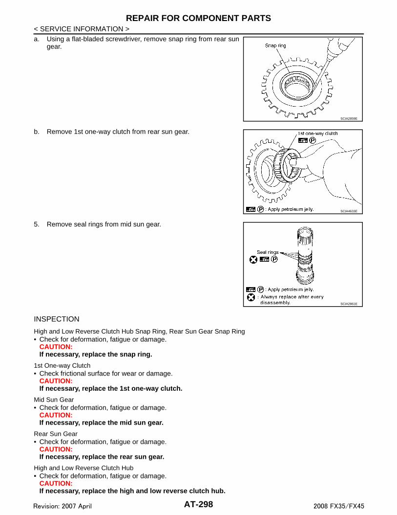
REPAIR FOR COMPONENT PARTS
< SERVICE INFORMATION >a. Using a flat-bladed screwdriver, remove snap ring from rear sungear.
b. Remove 1st one-way clutch from rear sun gear.
5. Remove seal rings from mid sun gear.
INSPECTION
High and Low Reverse Clutch Hub Snap Ring, Rear Sun Gear Snap Ring• Check for deformation, fatigue or damage.
CAUTION:If necessary, replace the snap ring.
1st One-way Clutch• Check frictional surface for wear or damage.
CAUTION:If necessary, replace the 1st one-way clutch.
Mid Sun Gear• Check for deformation, fatigue or damage.
CAUTION:If necessary, replace the mid sun gear.
Rear Sun Gear• Check for deformation, fatigue or damage.
CAUTION:If necessary, replace the rear sun gear.
High and Low Reverse Clutch Hub• Check for deformation, fatigue or damage.
CAUTION:If necessary, replace the high and low reverse clutch hub.
SCIA2859E
SCIA4633E
SCIA2861E
AT-298Revision: 2007 April 2008 FX35/FX45

REPAIR FOR COMPONENT PARTS
D
E
F
G
H
I
J
K
L
M
A
B
T
N
O
P
< SERVICE INFORMATION >
A
ASSEMBLY1. Install seal rings to mid sun gear.
CAUTION:• Do not reuse seal rings.• Apply petroleum jelly to seal rings.
2. Install 1st one-way clutch to rear sun gear.CAUTION:Apply petroleum jelly to 1st one-way clutch.
3. Using a flat-bladed screwdriver, install snap ring to rear sungear.
4. Install rear sun gear assembly to mid sun gear assembly.
SCIA2861E
SCIA4633E
SCIA2859E
SCIA2858E
AT-299Revision: 2007 April 2008 FX35/FX45

REPAIR FOR COMPONENT PARTS
< SERVICE INFORMATION >5. Install needle bearing to high and low reverse clutch hub.CAUTION:• Take care with the direction of needle bearing. Refer to
AT-264, "Location of Adjusting Shims, Needle Bearings,Thrust Washers and Snap Rings".
• Apply petroleum jelly to needle bearing.
6. Install high and low reverse clutch hub to mid sun gear assem-bly.
7. Using pair of snap ring pliers, install snap ring to mid sun gearassembly.CAUTION:Do not expand snap ring excessively.
8. Check operation of 1st one-way clutch.a. Hold mid sun gear and turn rear sun gear.b. Check 1st one-way clutch for correct locking and unlocking
directions.CAUTION:If not as shown in the figure, check installation direction of1st one-way clutch.
9. Install needle bearing and bearing races to high and low reverse clutch hub.CAUTION:• Take care with the direction of needle bearing . Refer to AT-264, "Location of Adjusting Shims,
Needle Bearings, Thrust Washers and Snap Rings".•Apply petroleum jelly to needle bearing and bearing races.
SCIA2857E
SCIA2856E
SCIA2855E
SCIA3132E
AT-300Revision: 2007 April 2008 FX35/FX45

REPAIR FOR COMPONENT PARTS
D
E
F
G
H
I
J
K
L
M
A
B
T
N
O
P
< SERVICE INFORMATION >
A
• VQ35DE models
• VK45DE models
High and Low Reverse Clutch INFOID:0000000001327408
COMPONENTS
VQ35DE models
SCIA2854E
SCIA5238E
SCIA5223E
1. High and low reverse clutch drum 2. Driven plate 3. Retaining plate
4. Snap ring 5. Drive plate 6. Bearing race
AT-301Revision: 2007 April 2008 FX35/FX45

REPAIR FOR COMPONENT PARTS
< SERVICE INFORMATION >VK45DE models
DISASSEMBLY1. Remove bearing race from high and low reverse clutch drum.
2. Using a flat-bladed screwdriver, remove snap ring from high andlow reverse clutch drum.
3. Remove drive plates, driven plates and retaining plate from highand low reverse clutch drum.
INSPECTION• Check the following, and replace high and low reverse clutch assembly if necessary.
High and Low Reverse Clutch Snap Ring• Check for deformation, fatigue or damage.
High and Low Reverse Clutch Drive Plates• Check facing for burns, cracks or damage.
High and Low Reverse Clutch Retaining Plates and Driven Plates• Check facing for burns, cracks or damage.
ASSEMBLY1. Install drive plates, driven plates and retaining plate in high and low reverse clutch drum.
SCIA5224E
1. High and low reverse clutch drum 2. Driven plate 3. Retaining plate
4. Snap ring 5. Drive plate 6. Bearing race
SCIA5215E
SCIA2868E
AT-302Revision: 2007 April 2008 FX35/FX45

REPAIR FOR COMPONENT PARTS
D
E
F
G
H
I
J
K
L
M
A
B
T
N
O
P
< SERVICE INFORMATION >
A
CAUTION:Take care with order of plates.
2. Using a flat-bladed screwdriver, install snap ring in high and lowreverse clutch drum.
3. Install bearing race to high and low reverse clutch drum.CAUTION:• Take care with the direction of needle bearing. Refer to
AT-264, "Location of Adjusting Shims, Needle Bearings,Thrust Washers and Snap Rings".
• Apply petroleum jelly to bearing race.
Direct Clutch INFOID:0000000001327409
COMPONENTS
VQ35DE models
SCIA2868E
SCIA5215E
SCIA7128E
1. Direct clutch drum 2. Driven plate 3. Retaining plate
4. Snap ring 5. Drive plate
AT-303Revision: 2007 April 2008 FX35/FX45

REPAIR FOR COMPONENT PARTS
< SERVICE INFORMATION >VK45DE models
DISASSEMBLY1. Using a flat-bladed screwdriver, remove snap ring from direct
clutch drum.2. Remove drive plates, driven plates, retaining plate and dish
plate* from direct clutch drum.*: VK45DE models
INSPECTION• Check the following, and replace direct clutch assembly if necessary.
Direct Clutch Snap Ring• Check for deformation, fatigue or damage.
Direct Clutch Drive Plates• Check facing for burns, cracks or damage.
Direct Clutch Retaining Plates, Driven Plates and Dish Plate*• Check facing for burns, cracks or damage.
*: VK45DE models
ASSEMBLY1. Install drive plates, driven plates, retaining plate and dish plate* in direct clutch drum.
*: VK45DE modelsCAUTION:Take care with order of plates.
SCIA6983E
1. Direct clutch drum 2. Driven plate 3. Retaining plate
4. Snap ring 5. Drive plate 6. Dish plate
SCIA2868E
AT-304Revision: 2007 April 2008 FX35/FX45
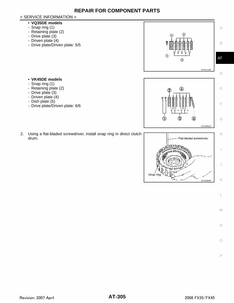
REPAIR FOR COMPONENT PARTS
D
E
F
G
H
I
J
K
L
M
A
B
T
N
O
P
< SERVICE INFORMATION >
A
• VQ35DE models- Snap ring (1)- Retaining plate (2)- Drive plate (3)- Driven plate (4)- Drive plate/Driven plate: 5/5
• VK45DE models- Snap ring (1)- Retaining plate (2)- Drive plate (3)- Driven plate (4)- Dish plate (5)- Drive plate/Driven plate: 6/6
2. Using a flat-bladed screwdriver, install snap ring in direct clutchdrum.
SCIA7134E
SCIA6951E
SCIA2868E
AT-305Revision: 2007 April 2008 FX35/FX45

ASSEMBLY
< SERVICE INFORMATION >ASSEMBLY
Assembly (1) INFOID:0000000001327410
1. As shown in the figure, use a drift [commercial service tool: 22mm (0.87 in) dia.] to drive manual shaft oil seals into the trans-mission case until it is flush.CAUTION:• Do not reuse manual shaft oil seals.• Apply ATF to manual shaft oil seals.
2. Install detent spring and spacer in transmission case, and thentighten detent spring and spacer mounting bolt to the specifiedtorque. Refer to AT-249, "Component".
3. Install manual shaft to transmission case.
4. Install parking rod to manual plate.
SCIA5259E
SCIA5248E
SCIA5716E
SCIA5220E
AT-306Revision: 2007 April 2008 FX35/FX45

ASSEMBLY
D
E
F
G
H
I
J
K
L
M
A
B
T
N
O
P
< SERVICE INFORMATION >
A
5. Install manual plate (with parking rod) to manual shaft.
6. Install retaining pin into the manual plate and manual shaft.a. Fit pinhole of the manual plate to pinhole of the manual shaft with a pin punch.b. Use a hammer to tap the retaining pin into the manual plate.
CAUTION:• Do not reuse retaining pin.• Drive retaining pin to 2±0.5 mm (0.08±0.020 in) over the
manual plate.
7. Install retaining pin into the transmission case and manual shaft.a. Fit pinhole of the transmission case to pinhole of the manual shaft with a pin punch.b. Use a hammer to tap the retaining pin into the transmission
case.CAUTION:• Do not reuse retaining pin.• Drive retaining pin to 5±1 mm (0.20±0.04 in) over the trans-
mission case.
8. Install O-rings to servo assembly.CAUTION:• Do not reuse O-rings.• Apply petroleum jelly to O-rings.
SCIA5715E
SCIA5297E
SCIA2427E
SCIA5719E
AT-307Revision: 2007 April 2008 FX35/FX45

ASSEMBLY
< SERVICE INFORMATION >9. Install return spring to servo assembly.10. Install servo assembly in transmission case.
11. Using pair of snap ring pliers, install snap ring to transmissioncase.
12. Install D-rings in reverse brake piston.CAUTION:• Do not reuse D-rings.• Apply ATF to D-rings.
13. Install reverse brake piston in transmission case.
SCIA5717E
SCIA5679E
SCIA2333E
SCIA5340E
SCIA2325E
AT-308Revision: 2007 April 2008 FX35/FX45

ASSEMBLY
D
E
F
G
H
I
J
K
L
M
A
B
T
N
O
P
< SERVICE INFORMATION >
A
14. Install needle bearing to drum support edge surface.CAUTION:• Take care with the direction of needle bearing. Refer to
AT-264, "Location of Adjusting Shims, Needle Bearings,Thrust Washers and Snap Rings".
• Apply petroleum jelly to needle bearing.
15. Install seal rings to drum support.CAUTION:• Do not reuse seal rings.• Apply petroleum jelly to seal rings.
16. Install spring retainer and return spring in transmission case.
17. Set the SST on spring retainer and install snap ring (fixing springretainer) in transmission case while compressing return spring.CAUTION:Securely assemble them using a flat-bladed screwdriver sothat snap ring tension is slightly weak.
SCIA2796E
SCIA3333E
SCIA2324E
SCIA5877E
AT-309Revision: 2007 April 2008 FX35/FX45

ASSEMBLY
< SERVICE INFORMATION >18. Install reverse brake drive plates, driven plates and dish plates in transmission case.CAUTION:Take care with order of plates.• VQ35DE models
• VK45DE models- Snap ring (1)- Retaining plate (2)- Drive plate (3)- Driven plate (4)- Dish plate (5)- Drive plate/Driven plate: 6/6
SCIA5250E
SCIA6949E
AT-310Revision: 2007 April 2008 FX35/FX45

ASSEMBLY
D
E
F
G
H
I
J
K
L
M
A
B
T
N
O
P
< SERVICE INFORMATION >
A
19. Assemble N-spring.20. Install reverse brake retaining plate in transmission case.
21. Install snap ring in transmission case.
22. Measure clearance between retaining plate and snap ring. If notwithin specified clearance, select proper retaining plate. Refer to“Parts Information” for retaining plate.
23. Install needle bearing to transmission case.CAUTION:• Take care with the direction of needle bearing. Refer to
AT-264, "Location of Adjusting Shims, Needle Bearings,Thrust Washers and Snap Rings".
• Apply petroleum jelly to needle bearing.
SCIA5249E
SCIA2439E
Specified clearance “A”Standard : 0.7 - 1.1 mm (0.028 - 0.043 in)
SCIA3129E
SCIA5031E
AT-311Revision: 2007 April 2008 FX35/FX45

ASSEMBLY
< SERVICE INFORMATION >24. Install revolution sensor to transmission case, and then tightenrevolution sensor mounting bolt to the specified torque. Refer toAT-249, "Component".CAUTION:• Do not subject it to impact by dropping or hitting it.• Do not disassemble.• Do not allow metal filings, etc. to get on the sensor's front
edge magnetic area.• Do not place in an area affected by magnetism.
25. As shown in the figure, use the drift to drive rear oil seal into therear extension (2WD models) or adapter case (AWD models)until it is flush.CAUTION:• Do not reuse rear oil seal.• Apply ATF to rear oil seal.
26. Install return spring to parking pawl.• VQ35DE models
SCIA2320E
SCIA5477E
SCIA2445E
AT-312Revision: 2007 April 2008 FX35/FX45

ASSEMBLY
D
E
F
G
H
I
J
K
L
M
A
B
T
N
O
P
< SERVICE INFORMATION >
A
• VK45DE models- Return spring (1)- Parking pawl (2)
27. Install parking pawl (with return spring) and pawl shaft to rearextension (2WD models) or adapter case (AWD models).
28. Install parking actuator support to rear extension (2WD models)or adapter case (AWD models).
29. Install needle bearing to rear extension (2WD models) oradapter case (AWD models).CAUTION:• Take care with the direction of needle bearing. Refer to
AT-264, "Location of Adjusting Shims, Needle Bearings,Thrust Washers and Snap Rings".
• Apply petroleum jelly to needle bearing.
30. Install seal rings to output shaft.CAUTION:• Do not reuse seal rings.• Apply petroleum jelly to seal rings.
SCIA6180J
SCIA3424E
SCIA3423E
SCIA5221E
SCIA5209E
AT-313Revision: 2007 April 2008 FX35/FX45

ASSEMBLY
< SERVICE INFORMATION >31. Install parking gear to output shaft.
32. Install output shaft in transmission case.CAUTION:Be careful not to mistake front for rear because both sideslooks similar. (Thinner end is front side.)
33. Install bearing race to output shaft.
34. Install rear extension assembly (2WD models) or adapter case assembly (AWD models) according to thefollowing procedures.
a. 2WD modelsi. Apply recommended sealant (Genuine Anaerobic Liquid Gasket
or equivalent. Refer to GI-44, "Recommended Chemical Productand Sealant".) to rear extension assembly as shown in the fig-ure.CAUTION:Completely remove all moisture, oil and old sealant, etc.from the transmission case and rear extension assemblymounting surfaces.
SCIA5247E
SCIA5030E
SCIA5245E
SCIA8228E
AT-314Revision: 2007 April 2008 FX35/FX45

ASSEMBLY
D
E
F
G
H
I
J
K
L
M
A
B
T
N
O
P
< SERVICE INFORMATION >
A
ii. Install rear extension assembly to transmission case.CAUTION:Insert the tip of parking rod between the parking pawl andthe parking actuator support when assembling the rearextension assembly.
iii. Tighten rear extension assembly mounting bolts to specifiedtorque. Refer to AT-249, "Component".CAUTION:Do not reuse self-sealing bolts.
b. AWD modelsi. Install gasket onto transmission case.
CAUTION:• Do not reuse gasket.• Completely remove all moisture, oil and old gasket, etc.
from the transmission case and adapter case assemblymounting surfaces.
ii. Install adapter case assembly to transmission case.CAUTION:Insert the tip of parking rod between the parking pawl andthe parking actuator support when assembling the rearextension assembly.
SCIA5029E
SCIA6941E
SCIA5231E
SCIA5186E
AT-315Revision: 2007 April 2008 FX35/FX45

ASSEMBLY
< SERVICE INFORMATION >iii. Tighten adapter case assembly mounting bolts (1) to specifiedtorque. [With bracket (2).] Refer to AT-249, "Component".: Bolt (10)
CAUTION:Do not reuse self-sealing bolts (3).Refer to GI section to mark sure icons (symbol marks) in the fig-ure. Refer to GI-8, "Component".
35. Install needle bearing in drum support.CAUTION:• Take care with the direction of needle bearing. Refer to
AT-264, "Location of Adjusting Shims, Needle Bearings,Thrust Washers and Snap Rings".
• Apply petroleum jelly to needle bearing.
36. Install direct clutch assembly in reverse brake.CAUTION:Make sure that drum support edge surface and direct clutchinner boss edge surface come to almost same place.
37. Install high and low reverse clutch assembly in direct clutch.
SCIA7210E
SCIA5198E
SCIA5019E
SCIA2306E
AT-316Revision: 2007 April 2008 FX35/FX45

ASSEMBLY
D
E
F
G
H
I
J
K
L
M
A
B
T
N
O
P
< SERVICE INFORMATION >
A
38. Using a flat-bladed screwdriver, align drive plate.
39. Install high and low reverse clutch hub, mid sun gear assemblyand rear sun gear assembly as a unit.
CAUTION:Check that portion “A” of high and low reverse clutch drumprotrudes approximately 2 mm (0.08 in) beyond portion “B”of rear sun gear.
40. Install needle bearing in rear carrier assembly.CAUTION:• Take care with the direction of needle bearing. Refer to
AT-264, "Location of Adjusting Shims, Needle Bearings,Thrust Washers and Snap Rings".
• Apply petroleum jelly to needle bearing.
SCIA3169E
SCIA5018E
SCIA3130E
SCIA2803E
AT-317Revision: 2007 April 2008 FX35/FX45

ASSEMBLY
< SERVICE INFORMATION >41. Install bearing race in rear carrier assembly.CAUTION:Apply petroleum jelly to bearing race.
42. Install rear carrier assembly in direct clutch drum.
43. Install needle bearing (rear side) to mid carrier assembly.CAUTION:• Take care with the direction of needle bearing. Refer to
AT-264, "Location of Adjusting Shims, Needle Bearings,Thrust Washers and Snap Rings".
• Apply petroleum jelly to needle bearing.
44. Install needle bearing (front side) to mid carrier assembly.CAUTION:• Take care with the direction of needle bearing. Refer to
AT-264, "Location of Adjusting Shims, Needle Bearings,Thrust Washers and Snap Rings".
• Apply petroleum jelly to needle bearing.
45. Install mid carrier assembly in rear carrier assembly.
SCIA5175E
SCIA2462E
SCIA2804E
SCIA2805E
SCIA5017E
AT-318Revision: 2007 April 2008 FX35/FX45

ASSEMBLY
D
E
F
G
H
I
J
K
L
M
A
B
T
N
O
P
< SERVICE INFORMATION >
A
46. Install front carrier assembly, input clutch assembly and rearinternal gear as a unit.
47. Install seal rings in input clutch assembly.CAUTION:• Do not reuse seal rings.• Apply petroleum jelly to seal rings.
48. Install band servo anchor end pin and lock nut in transmissioncase.CAUTION:Do not reuse band servo anchor end pin.
49. Install brake band in transmission case.CAUTION:Assemble it so that identification to avoid incorrect installa-tion faces servo side.
50. Install front sun gear to front carrier assembly.CAUTION:Apply ATF to front sun gear bearing and 3rd one-way clutchend bearing.
SCIA5015E
SCIA2470E
SCIA6512E
SCIA5498E
SCIA5014E
AT-319Revision: 2007 April 2008 FX35/FX45

ASSEMBLY
< SERVICE INFORMATION >51. Install needle bearing to front sun gear.CAUTION:• Take care with the direction of needle bearing. Refer to
AT-264, "Location of Adjusting Shims, Needle Bearings,Thrust Washers and Snap Rings".
• Apply petroleum jelly to needle bearing.
52. Adjust brake band tilting using clips so that brake band contactsfront sun gear drum evenly.
53. Adjust brake band.a. Loosen lock nut.b. Tighten band servo anchor end pin to the specified torque.
c. Back of band servo anchor end pin three turns.d. Holding band servo anchor end pin, tighten lock nut to the spec-
ified torque. Refer to AT-249, "Component".
Adjustment INFOID:0000000001327411
TOTAL END PLAY• Measure clearance between front sun gear and bearing race for oil
pump cover.• Select proper thickness of bearing race so that end play is within
specifications.
SCIA2808E
SCIA5033E
: 5.0 N·m (0.51 kg-m, 44 in-lb)
SCIA5498E
SCIA2810E
AT-320Revision: 2007 April 2008 FX35/FX45

ASSEMBLY
D
E
F
G
H
I
J
K
L
M
A
B
T
N
O
P
< SERVICE INFORMATION >
A
1. Measure dimensions “K” and “L” and then calculate dimension“J”.
a. Measure dimension “K”.
b. Measure dimension “L”.c. Calculate dimension “J”.
2. Measure dimensions “M1” and “M2” and then calculate dimen-sion “M”.
a. Place bearing race and needle bearing on oil pump assembly.
SCIA7073E
SCIA7074E
“J” : Distance between oil pump fitting surface of transmission case and needle bearing mating surface of front sun gear.J = K – L
SCIA5352E
SCIA3125E
SCIA3124E
AT-321Revision: 2007 April 2008 FX35/FX45

ASSEMBLY
< SERVICE INFORMATION >b. Measure dimension “M1”.
c. Measure dimension “M2”.
d. Calculate dimension “M”.
3. Adjust total end play “T1”.
• Select proper thickness of bearing race so that total end playis within specifications. Refer to “Parts Information” for bearingrace selection.
SCIA3126E
SCIA3127E
“M” : Distance between transmission case fitting surface of oil pump and needle bearing on oil pump.M = M1 – M2
SCIA3125E
T1 = J – MTotal end play “T1”
: 0.25 - 0.55 mm (0.0098 - 0.0217 in)
SCIA2810E
AT-322Revision: 2007 April 2008 FX35/FX45

ASSEMBLY
D
E
F
G
H
I
J
K
L
M
A
B
T
N
O
P
< SERVICE INFORMATION >
A
Assembly (2) INFOID:0000000001327412
1. Install O-ring to oil pump assembly.CAUTION:• Do not reuse O-ring.• Apply ATF to O-ring.
2. Install bearing race to oil pump assembly.CAUTION:Apply petroleum jelly to bearing race.
3. Install oil pump assembly in transmission case.CAUTION:Apply ATF to oil pump bearing.
4. Apply recommended sealant (Genuine RTV Silicone Sealant orequivalent. Refer to GI-44, "Recommended Chemical Productand Sealant".) to oil pump assembly as shown in the figure.CAUTION:Completely remove all moisture, oil and old sealant, etc.From the oil pump mounting bolts and oil pump mountingbolt mounting surfaces.
SCIA5172E
SCIA6529E
SCIA2811E
SCIA5321E
AT-323Revision: 2007 April 2008 FX35/FX45

ASSEMBLY
< SERVICE INFORMATION >5. Tighten oil pump mounting bolts to specified torque. Refer to AT-249, "Component".CAUTION:Apply ATF to oil pump bushing.
6. Install O-ring to input clutch assembly.CAUTION:• Do not reuse O-ring.• Apply ATF to O-ring.
7. Install converter housing to transmission case, and then tightenconverter housing mounting bolts (1) to the specified torque.Refer to AT-249, "Component".• : Bolt (8)CAUTION:Do not reuse self-sealing bolt (2).
8. Make sure that brake band does not close turbine revolutionsensor hole.
9. Install control valve with TCM.a. Connect TCM connector and park/neutral position switch con-
nector.
SCIA2300E
SCIA5011E
SCIA7985E
SCIA5034E
SCIA5449E
AT-324Revision: 2007 April 2008 FX35/FX45

ASSEMBLY
D
E
F
G
H
I
J
K
L
M
A
B
T
N
O
P
< SERVICE INFORMATION >
A
b. Install A/T assembly harness connector from control valve withTCM.
c. Connect TCM connectors.
d. Install O-ring to A/T assembly harness connector.CAUTION:• Do not reuse O-ring.• Apply ATF to O-ring.
e. Install A/T fluid temperature sensor 2 to bracket.
f. Install A/T fluid temperature sensor 2 (with bracket) in controlvalve with TCM, and then tighten A/T fluid temperature sensor 2mounting bolts to the specified torque. Refer to AT-249, "Com-ponent".CAUTION:Adjust bolt hole of bracket to bolt hole of control valve.
SCIA5450E
SCIA5447E
SCIA5155E
SCIA5264E
SCIA5301E
AT-325Revision: 2007 April 2008 FX35/FX45
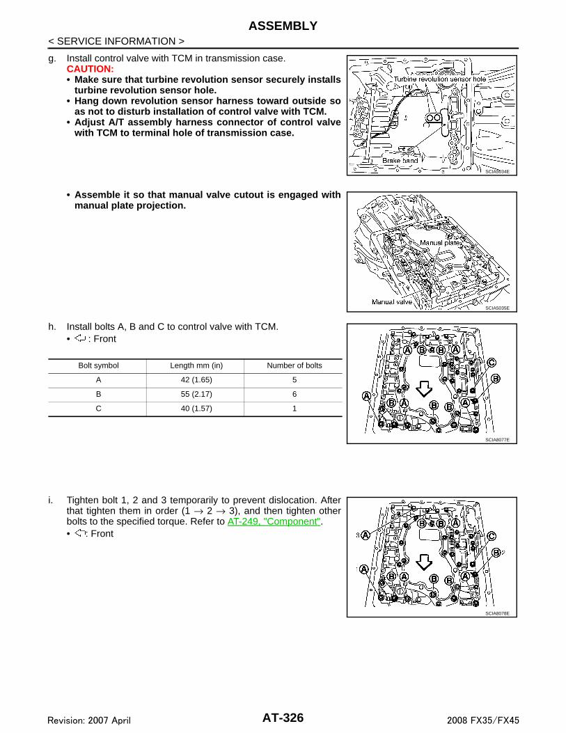
ASSEMBLY
< SERVICE INFORMATION >g. Install control valve with TCM in transmission case.CAUTION:• Make sure that turbine revolution sensor securely installs
turbine revolution sensor hole.• Hang down revolution sensor harness toward outside so
as not to disturb installation of control valve with TCM.• Adjust A/T assembly harness connector of control valve
with TCM to terminal hole of transmission case.
• Assemble it so that manual valve cutout is engaged withmanual plate projection.
h. Install bolts A, B and C to control valve with TCM.• : Front
i. Tighten bolt 1, 2 and 3 temporarily to prevent dislocation. Afterthat tighten them in order (1 → 2 → 3), and then tighten otherbolts to the specified torque. Refer to AT-249, "Component".• : Front
SCIA5034E
SCIA5035E
Bolt symbol Length mm (in) Number of bolts
A 42 (1.65) 5
B 55 (2.17) 6
C 40 (1.57) 1
SCIA8077E
SCIA8078E
AT-326Revision: 2007 April 2008 FX35/FX45

ASSEMBLY
D
E
F
G
H
I
J
K
L
M
A
B
T
N
O
P
< SERVICE INFORMATION >
A
10. Connect A/T fluid temperature sensor 2 connector (1).11. Securely fasten terminal cord assembly and A/T fluid tempera-
ture sensor 2 harness with terminal clips ( ).
12. Connect revolution sensor connector.
13. Securely fasten revolution sensor 2 harness with terminal clip.
14. Pull down A/T assembly harness connector.CAUTION:Be careful not to damage connector.
15. Install snap ring to A/T assembly harness connector.
SCIA8069E
SCIA7524E
SCIA7526E
SCIA5299E
SCIA5300E
AT-327Revision: 2007 April 2008 FX35/FX45

ASSEMBLY
< SERVICE INFORMATION >16. Install magnets in oil pan.
17. Install oil pan to transmission case.a. Install oil pan gasket to transmission case.
CAUTION:• Do not reuse oil pan gasket.• Install it in the direction to align hole positions.• Complete remove all moisture, oil and old gasket, etc. from oil pan gasket mounting surface.
b. Install oil pan (3) (with oil pan gasket), clips (2) and brackets (1)(VK45DE) to transmission case.• : Vehicle front• : Bolt (22)CAUTION:• Install it so that drain plug (4) comes to the position as
shown in the figure.• Be careful not to pinch harnesses.• Completely remove all moisture, oil and old gasket, etc.
from oil pan gasket mounting surface.
c. Tighten oil pan mounting bolts to the specified torque in numeri-cal order shown in the figure after temporarily tightening them.Refer to AT-249, "Component".CAUTION:Do not reuse oil pan mounting bolts.
18. Install drain plug to oil pan, and then tighten drain plug mountingbolts to the specified torque. Refer to AT-249, "Component".CAUTION:Do not reuse drain plug gasket.
19. Install torque converter.a. Pour ATF into torque converter.
• Approximately 2 liter (2-1/8 US qt, 1-3/4 Imp qt) of ATF isrequired for a new torque converter.
• When reusing old torque converter, add the same amountof ATF as was drained.
SCIA5200E
SCIA8128E
SCIA4113E
SAT428DA
AT-328Revision: 2007 April 2008 FX35/FX45

ASSEMBLY
D
E
F
G
H
I
J
K
L
M
A
B
T
N
O
P
< SERVICE INFORMATION >
A
b. Install torque converter while aligning notches of torque con-verter with notches of oil pump.CAUTION:Install torque converter while rotating it.
c. Measure distance “A” to check that torque converter is in properposition.
SCIA5010E
Distance “A”VQ35DE models : 25.0 mm (0.98 in) or moreVK45DE models : 22.0 mm (0.87 in) or more
SAT017B
AT-329Revision: 2007 April 2008 FX35/FX45
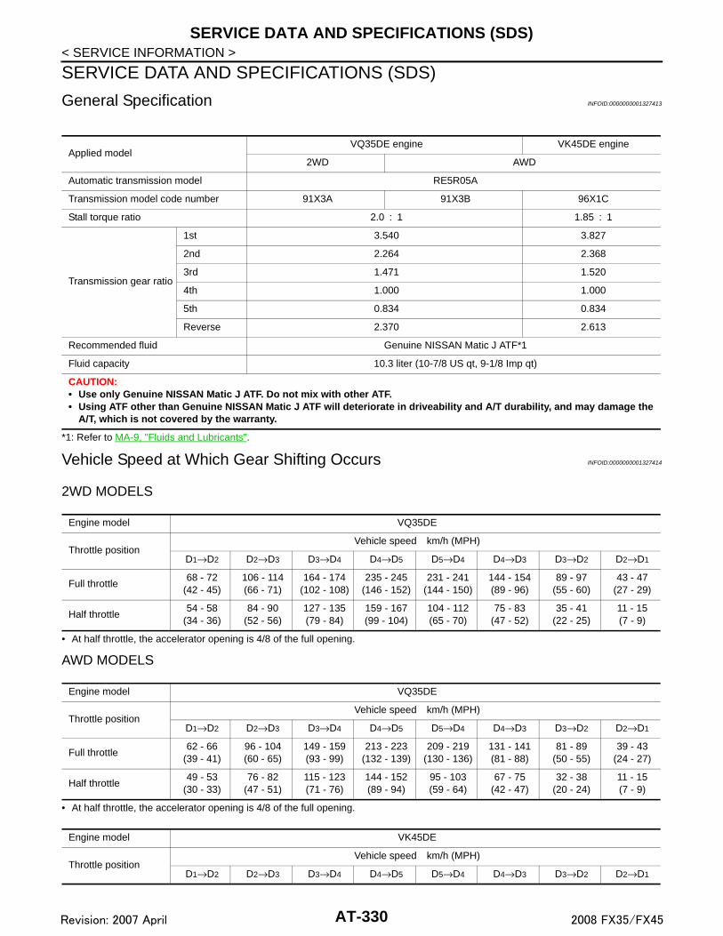
SERVICE DATA AND SPECIFICATIONS (SDS)
< SERVICE INFORMATION >SERVICE DATA AND SPECIFICATIONS (SDS)
General Specification INFOID:0000000001327413
*1: Refer to MA-9, "Fluids and Lubricants".
Vehicle Speed at Which Gear Shifting Occurs INFOID:0000000001327414
2WD MODELS
• At half throttle, the accelerator opening is 4/8 of the full opening.
AWD MODELS
• At half throttle, the accelerator opening is 4/8 of the full opening.
Applied modelVQ35DE engine VK45DE engine
2WD AWD
Automatic transmission model RE5R05A
Transmission model code number 91X3A 91X3B 96X1C
Stall torque ratio 2.0 : 1 1.85 : 1
Transmission gear ratio
1st 3.540 3.827
2nd 2.264 2.368
3rd 1.471 1.520
4th 1.000 1.000
5th 0.834 0.834
Reverse 2.370 2.613
Recommended fluid Genuine NISSAN Matic J ATF*1
Fluid capacity 10.3 liter (10-7/8 US qt, 9-1/8 Imp qt)
CAUTION:• Use only Genuine NISSAN Matic J ATF. Do not mix with other ATF.• Using ATF other than Genuine NISSAN Matic J ATF will deteriorate in driveability and A/T durability, and may damage the
A/T, which is not covered by the warranty.
Engine model VQ35DE
Throttle positionVehicle speed km/h (MPH)
D1→D2 D2→D3 D3→D4 D4→D5 D5→D4 D4→D3 D3→D2 D2→D1
Full throttle 68 - 72
(42 - 45)106 - 114(66 - 71)
164 - 174(102 - 108)
235 - 245(146 - 152)
231 - 241(144 - 150)
144 - 154(89 - 96)
89 - 97(55 - 60)
43 - 47(27 - 29)
Half throttle 54 - 58
(34 - 36)84 - 90
(52 - 56)127 - 135(79 - 84)
159 - 167(99 - 104)
104 - 112(65 - 70)
75 - 83(47 - 52)
35 - 41(22 - 25)
11 - 15(7 - 9)
Engine model VQ35DE
Throttle positionVehicle speed km/h (MPH)
D1→D2 D2→D3 D3→D4 D4→D5 D5→D4 D4→D3 D3→D2 D2→D1
Full throttle 62 - 66
(39 - 41)96 - 104(60 - 65)
149 - 159(93 - 99)
213 - 223(132 - 139)
209 - 219(130 - 136)
131 - 141(81 - 88)
81 - 89(50 - 55)
39 - 43(24 - 27)
Half throttle 49 - 53
(30 - 33)76 - 82
(47 - 51)115 - 123(71 - 76)
144 - 152(89 - 94)
95 - 103(59 - 64)
67 - 75(42 - 47)
32 - 38(20 - 24)
11 - 15(7 - 9)
Engine model VK45DE
Throttle positionVehicle speed km/h (MPH)
D1→D2 D2→D3 D3→D4 D4→D5 D5→D4 D4→D3 D3→D2 D2→D1
AT-330Revision: 2007 April 2008 FX35/FX45

SERVICE DATA AND SPECIFICATIONS (SDS)
D
E
F
G
H
I
J
K
L
M
A
B
T
N
O
P
< SERVICE INFORMATION >
A
• At half throttle, the accelerator opening is 4/8 of the full opening.
Vehicle Speed at Which Lock-up Occurs/Releases INFOID:0000000001327415
2WD MODELS
• At closed throttle, the accelerator opening is less than 1/8 condition. (Closed throttle position signal: OFF)
• At half throttle, the accelerator opening is 4/8 of the full opening.
AWD MODELS
• At closed throttle, the accelerator opening is less than 1/8 condition. (Closed throttle position signal: OFF)
• At half throttle, the accelerator opening is 4/8 of the full opening.
• At closed throttle, the accelerator opening is less than 1/8 condition. (Closed throttle position signal: OFF)
• At half throttle, the accelerator opening is 4/8 of the full opening.
Stall Speed INFOID:0000000001327416
Line Pressure INFOID:0000000001327417
Full throttle 59 - 63
(37 - 39)95 - 103(59 - 64)
147 - 157(92 - 98)
219 - 229(137 - 143)
215 - 225(134 - 141)
130 - 140(81 - 88)
82 - 90(51 - 56)
35 - 39(22 - 24)
Half throttle 48 - 52
(30 - 33)78 - 84
(48 - 52)122 - 130(76 - 81)
154 - 162(96 - 101)
122 - 130(76 - 81)
68 - 76(42 - 47)
40 - 46(25 - 29)
9 - 13(6 - 8)
Engine model VQ35DE
Throttle positionVehicle speed km/h (MPH)
Lock-up ON Lock-up OFF
Closed throttle 65 - 73 (40 - 45) 62 - 70 (39 - 43)
Half throttle 196 - 204 (122 - 127) 153 - 161 (95 - 100)
Engine model VQ35DE
Throttle positionVehicle speed km/h (MPH)
Lock-up ON Lock-up OFF
Closed throttle 59 - 67 (37 - 42) 56 - 64 (35 - 40)
Half throttle 178 - 186 (111 - 116) 139 - 147 (86 - 91)
Engine model VK45DE
Throttle positionVehicle speed km/h (MPH)
Lock-up ON Lock-up OFF
Closed throttle 66 - 74 (41 - 46) 53 - 61 (33 - 38)
Half throttle 191 - 199 (119 - 124) 145 - 153 (90 - 95)
Engine model VQ35DE VK45DE
Stall speed 2,650 - 2,950 rpm 2,260 - 2,560 rpm
Engine speedLine pressure kPa (kg/cm2, psi)
“R” position “D” and “M” positions
At idle speed 425 - 465 (4.3 - 4.7, 62 - 67) 379 - 428 (3.9 - 4.4, 55 - 62)
At stall speed 1,605 - 1,950 (16.4 - 19.9, 233 - 283) 1,310 - 1,500 (13.4 - 15.3, 190 - 218)
AT-331Revision: 2007 April 2008 FX35/FX45

SERVICE DATA AND SPECIFICATIONS (SDS)
< SERVICE INFORMATION >A/T Fluid Temperature Sensor INFOID:0000000001327418
Turbine Revolution Sensor INFOID:0000000001327419
Vehicle Speed Sensor A/T (Revolution Sensor) INFOID:0000000001327420
Reverse Brake INFOID:0000000001327421
Total End Play INFOID:0000000001327422
Name Condition CONSULT-III “DATA MONITOR” (Approx.) Resistance (Approx.)
A/T fluid temperature sensor 1
0°C (32°F) 3.3 V 15 kΩ
20°C (68°F) 2.7 V 6.5 kΩ
80°C (176°F) 0.9 V 0.9 kΩ
A/T fluid temperature sensor 2
0°C (32°F) 3.3 V 10 kΩ
20°C (68°F) 2.5 V 4 kΩ
80°C (176°F) 0.7 V 0.5 kΩ
Name Condition Data (Approx.)
Turbine revolution sensor 1When running at 50 km/h (31 MPH) in 4th speed with the closed throttle po-sition signal OFF.
1.3 kHz
Turbine revolution sensor 2When moving at 20 km/h (12 MPH) in 1st speed with the closed throttle po-sition signal OFF.
Name Condition Data (Approx.)
Revolution sensor When moving at 20 km/h (12 MPH). 185 Hz
Model code number 91X3A, 91X3B 96X1C
Number of drive plates 6
Number of driven plates 6
Clearance mm (in) Standard 0.7 - 1.1 (0.028 - 0.043)
Total end play mm (in) 0.25 - 0.55 (0.0098 - 0.0217)
AT-332Revision: 2007 April 2008 FX35/FX45


