307-01-Automatic Transaxle-Transmission - 5R55S...
29
Transmission SECTION 307-01: Automatic Transaxle/Transmission — 5R55S 2009 Mustang Workshop Manual DISASSEMBLY Procedure revision date: 06/30/2009 Special Tool(s) Compressor, Servo Cover 307-402 Handle, Torque Converter 307-091 (T81P-7902-C) Holding Fixture, Transmission 307-003 (T57L-500-B) Remover, Input Shaft Oil Seal 308-375 Remover, Output Flange 307-523 Remover, Torque Converter Fluid Seal 307-309 (T94P-77001-BH) Remover, Transmission Fluid Pump 307-397 Slide Hammer 100-001 (T50T-100-A)
Transcript of 307-01-Automatic Transaxle-Transmission - 5R55S...

Transmission
SECTION 307-01: Automatic Transaxle/Transmission — 5R55S 2009 Mustang Workshop Manual DISASSEMBLY Procedure revision date: 06/30/2009
Special Tool(s)
Compressor, Servo Cover 307-402
Handle, Torque Converter 307-091 (T81P-7902-C)
Holding Fixture, Transmission 307-003 (T57L-500-B)
Remover, Input Shaft Oil Seal 308-375
Remover, Output Flange 307-523
Remover, Torque Converter Fluid Seal 307-309 (T94P-77001-BH)
Remover, Transmission Fluid Pump 307-397
Slide Hammer 100-001 (T50T-100-A)

1. NOTE: Tag and identify all parts for reassembly.
Place the transmission on a bench.
2. WARNING: Secure the torque converter in the transmission during removal or installation. The torque converter is heavy and may result in injury if it falls out of the transmission. Failure to follow this instruction may result in serious personal injury.
NOTE: If not installing a new torque converter, leave the adapter plate screwed to the torque converter.
Using the Torque Converter Handles, remove the torque converter and adapter plate as an assembly.
3. If the vehicle is equipped, and installation of a new or remanufactured torque converter is necessary, remove the torque converter adapter plate.
4. If the adapter plate has been removed, use the Torque Converter Handles to remove the torque converter.

5. Remove the input shaft.
6. Using the Transmission Holding Fixture, install the transmission on to the bench with the torque converter housing facing up.
7. Remove the transmission sensors.

8. Remove the Transmission Range (TR) sensor.
9. Remove and discard the output shaft flange nut.
10. Using the Output Flange Remover, remove the output shaft flange.
11. Using the Torque Converter Fluid Seal Remover and Slide Hammer, remove the extension housing seal.
12. NOTE: The parking pawl, parking pawl return spring and parking pawl shaft may fall out during removal of the extension housing.
Remove the extension housing.
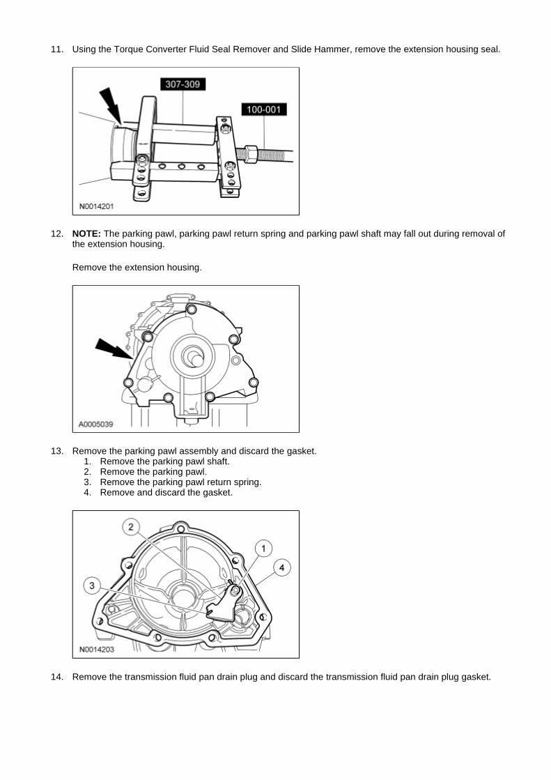
13. Remove the parking pawl assembly and discard the gasket. 1. Remove the parking pawl shaft. 2. Remove the parking pawl. 3. Remove the parking pawl return spring. 4. Remove and discard the gasket.
14. Remove the transmission fluid pan drain plug and discard the transmission fluid pan drain plug gasket.
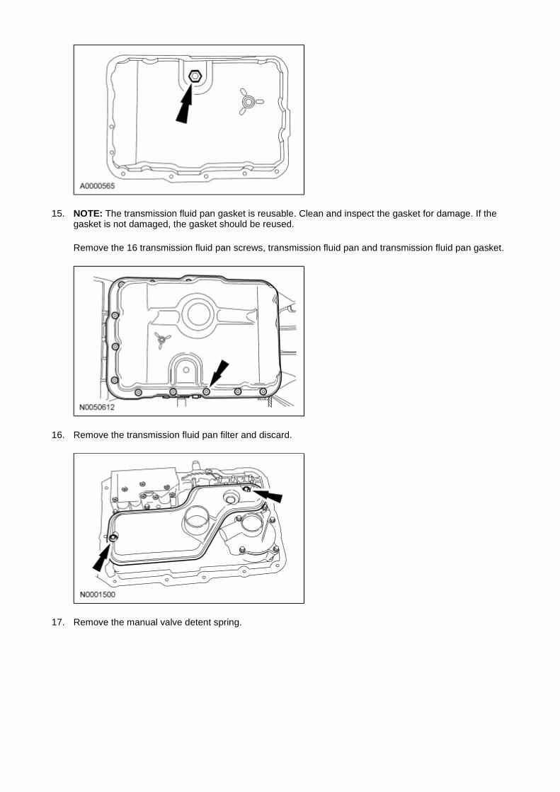
15. NOTE: The transmission fluid pan gasket is reusable. Clean and inspect the gasket for damage. If the gasket is not damaged, the gasket should be reused.
Remove the 16 transmission fluid pan screws, transmission fluid pan and transmission fluid pan gasket.
16. Remove the transmission fluid pan filter and discard.
17. Remove the manual valve detent spring.
18. WARNING: Follow the specified procedure when using the tool to remove the servo cover. The servo and servo cover are under high spring force and can separate forcefully, which may result in serious personal injury.
Remove the reverse servo assembly.
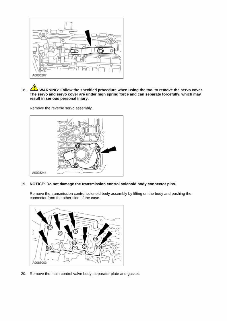
19. NOTICE: Do not damage the transmission control solenoid body connector pins.
Remove the transmission control solenoid body assembly by lifting on the body and pushing the connector from the other side of the case.
20. Remove the main control valve body, separator plate and gasket.
21. Using the Input Shaft Oil Seal Remover and Slide Hammer, remove the front fluid pump seal.
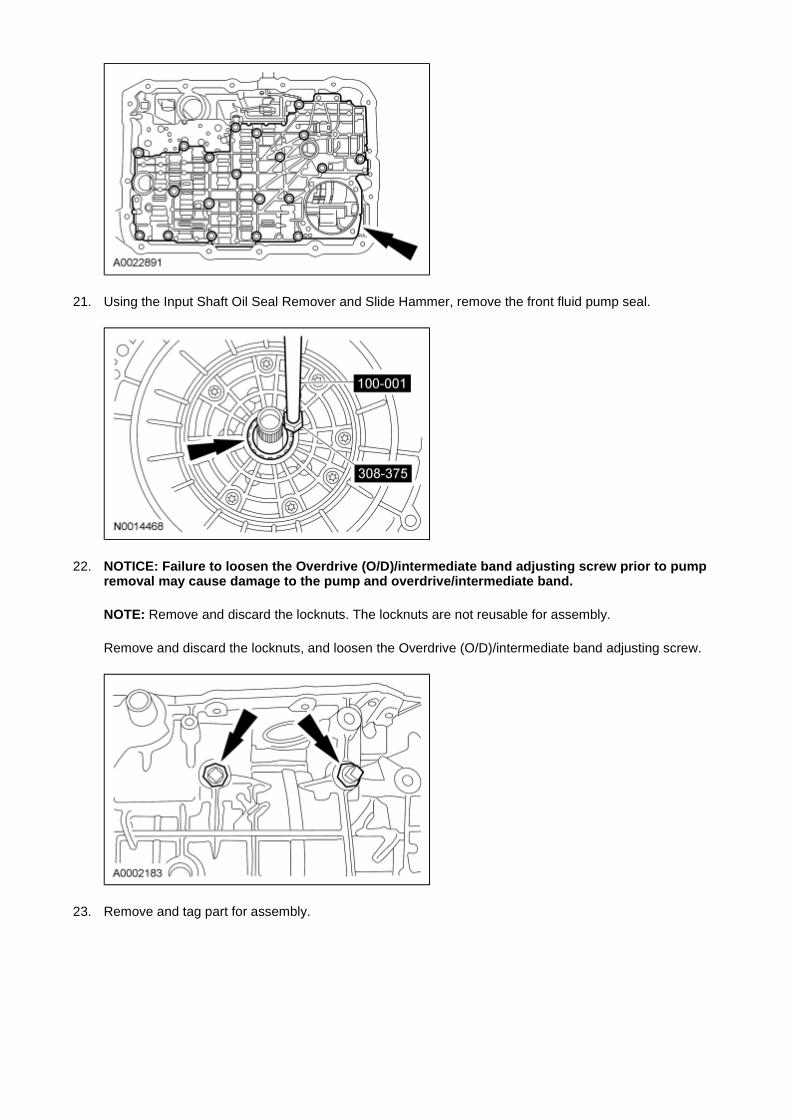
22. NOTICE: Failure to loosen the Overdrive (O/D)/intermediate band adjusting screw prior to pump removal may cause damage to the pump and overdrive/intermediate band.
NOTE: Remove and discard the locknuts. The locknuts are not reusable for assembly.
Remove and discard the locknuts, and loosen the Overdrive (O/D)/intermediate band adjusting screw.
23. Remove and tag part for assembly.
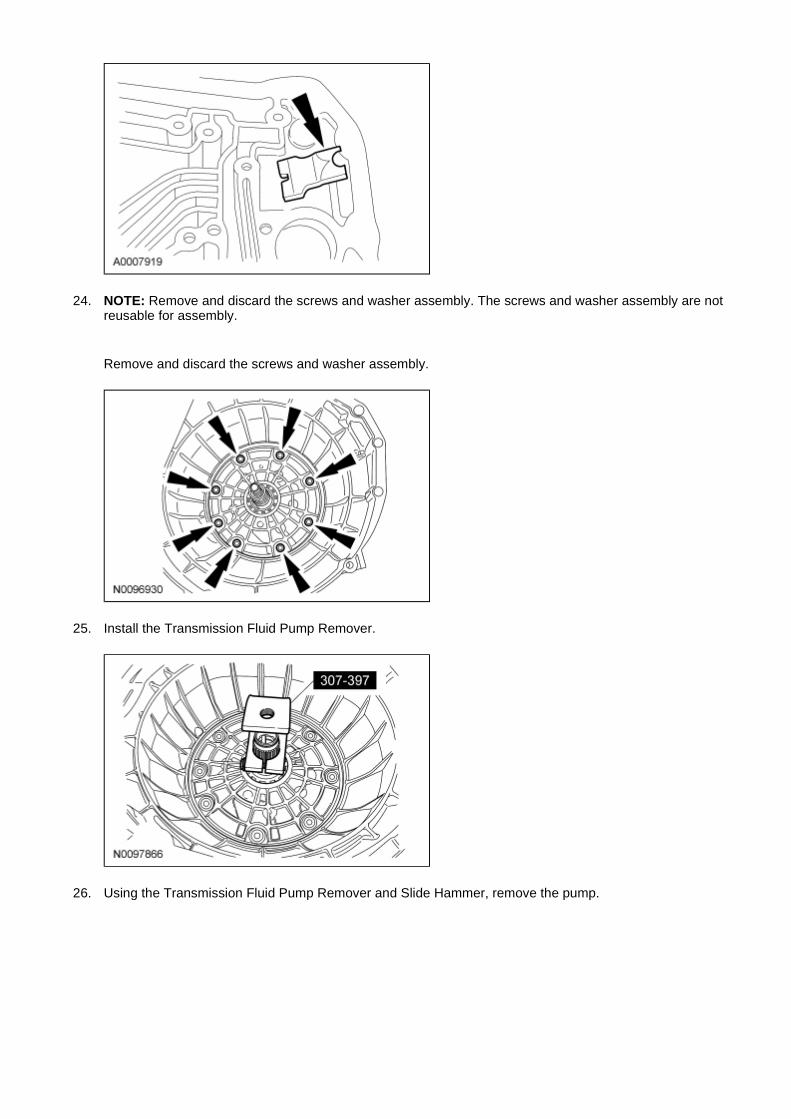
24. NOTE: Remove and discard the screws and washer assembly. The screws and washer assembly are not reusable for assembly.
Remove and discard the screws and washer assembly.
25. Install the Transmission Fluid Pump Remover.
26. Using the Transmission Fluid Pump Remover and Slide Hammer, remove the pump.

27. WARNING: Follow the specified procedure when using the tool to remove the servo cover. The servo and servo cover are under high spring force and can separate forcefully, which may result in serious personal injury.
Using the Servo Cover Compressor, remove the intermediate servo cover retaining ring.
28. Remove the intermediate band servo piston and spring.
29. After removing the intermediate band servo piston and spring, inspect the transmission case servo bore for excessive wear. If excessive wear or damage to the transmission case is evident, repair the transmission case servo bore using the servo bore repair kit.
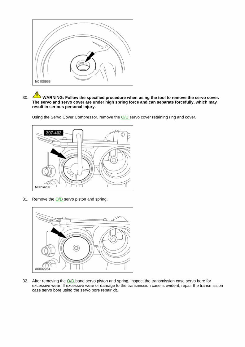
30. WARNING: Follow the specified procedure when using the tool to remove the servo cover. The servo and servo cover are under high spring force and can separate forcefully, which may result in serious personal injury.
Using the Servo Cover Compressor, remove the O/D servo cover retaining ring and cover.
31. Remove the O/D servo piston and spring.
32. After removing the O/D band servo piston and spring, inspect the transmission case servo bore for excessive wear. If excessive wear or damage to the transmission case is evident, repair the transmission case servo bore using the servo bore repair kit.
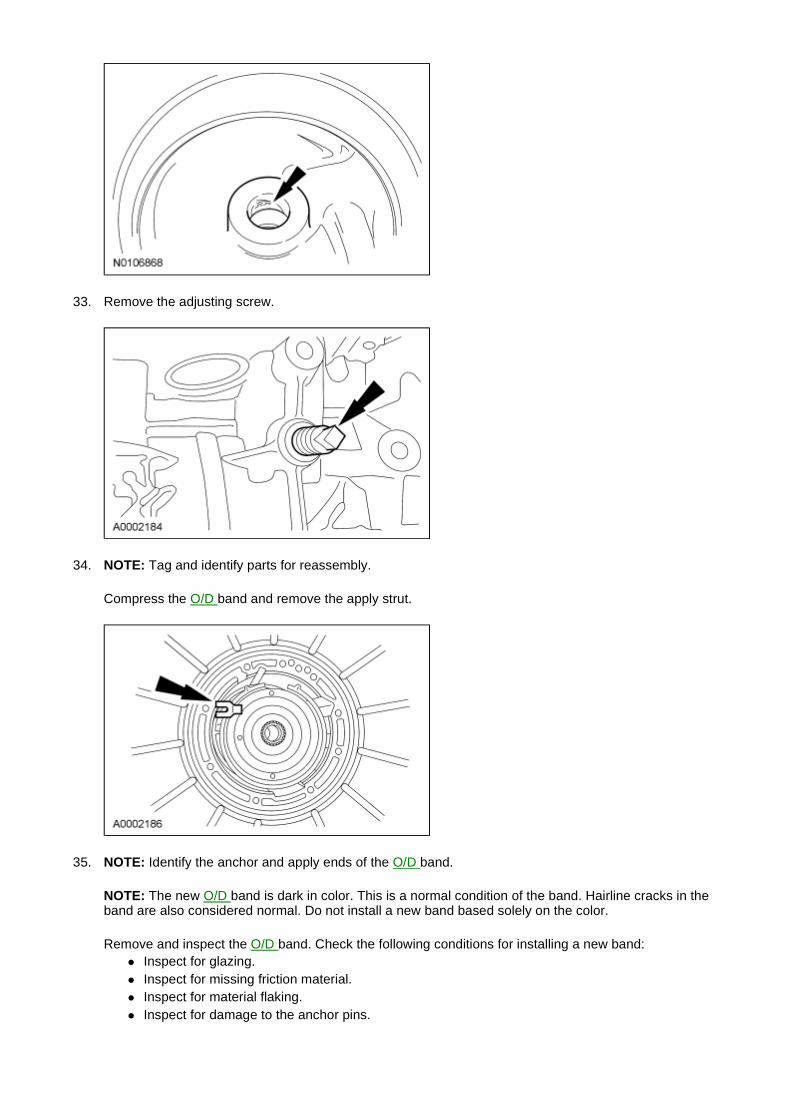
33. Remove the adjusting screw.
34. NOTE: Tag and identify parts for reassembly.
Compress the O/D band and remove the apply strut.
35. NOTE: Identify the anchor and apply ends of the O/D band.
NOTE: The new O/D band is dark in color. This is a normal condition of the band. Hairline cracks in the band are also considered normal. Do not install a new band based solely on the color.
Remove and inspect the O/D band. Check the following conditions for installing a new band: � Inspect for glazing. � Inspect for missing friction material. � Inspect for material flaking. � Inspect for damage to the anchor pins.
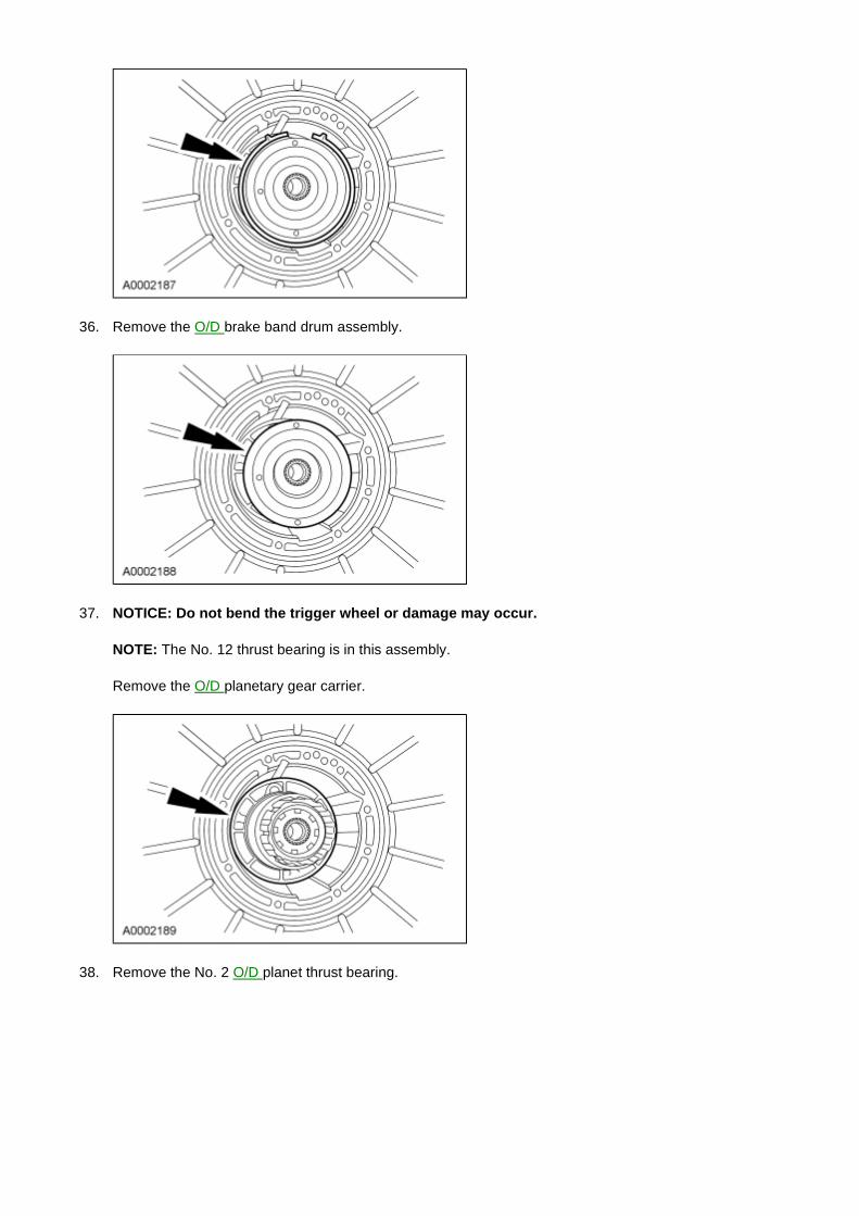
36. Remove the O/D brake band drum assembly.
37. NOTICE: Do not bend the trigger wheel or damage may occur.
NOTE: The No. 12 thrust bearing is in this assembly.
Remove the O/D planetary gear carrier.
38. Remove the No. 2 O/D planet thrust bearing.
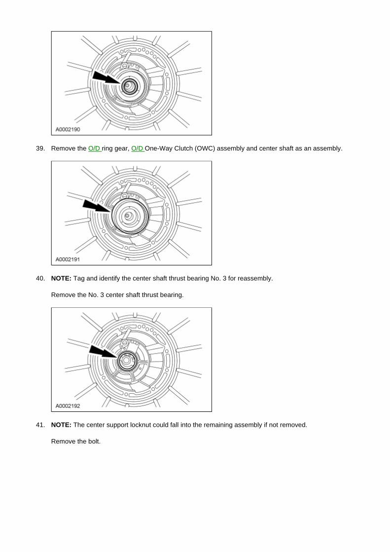
39. Remove the O/D ring gear, O/D One-Way Clutch (OWC) assembly and center shaft as an assembly.
40. NOTE: Tag and identify the center shaft thrust bearing No. 3 for reassembly.
Remove the No. 3 center shaft thrust bearing.
41. NOTE: The center support locknut could fall into the remaining assembly if not removed.
Remove the bolt.

42. Remove the locknut and cage.
43. Remove the center support retaining ring.
44. NOTE: The center support is repaired as an assembly. Any damage requires installing a new component.
NOTE: When removing the center support, pull evenly around the center support web.
Remove the center support.

45. Inspect the center support assembly for wear or damage. 1. Inspect the thrust surfaces for wear or damage. 2. Inspect the center support sealing surface. 3. Inspect the fluid passage for blockage or damage.
46. Inspect the seal rings for damage.
47. Inspect the bearing for missing rollers or damage.

48. Inspect the direct clutch feed hole for blockage or damage. 1. Rotate the center support bearing to locate the direct clutch feed hole. 2. Inspect the direct clutch feed hole for blockage or damage.
49. NOTE: Tag and identify the No. 4 intermediate clutch drum thrust bearing.
Remove the intermediate brake drum thrust bearing (No. 4).
50. Remove, tag and identify the band anchor strut for assembly.
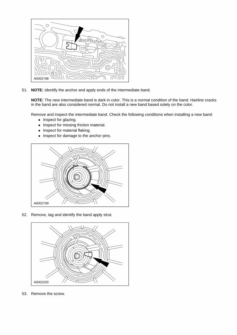
51. NOTE: Identify the anchor and apply ends of the intermediate band.
NOTE: The new intermediate band is dark in color. This is a normal condition of the band. Hairline cracks in the band are also considered normal. Do not install a new band based solely on the color.
Remove and inspect the intermediate band. Check the following conditions when installing a new band: � Inspect for glazing. � Inspect for missing friction material. � Inspect for material flaking. � Inspect for damage to the anchor pins.
52. Remove, tag and identify the band apply strut.
53. Remove the screw.

54. NOTE: The No. 5 forward clutch cylinder thrust bearing may come out with the intermediate brake and direct clutch drum.
Remove the direct clutch drum.
55. Remove the No. 5 forward clutch cylinder thrust bearing, tag and identify.
56. NOTE: The No. 6A thrust bearing may come out with the cylinder. Tag and identify for reassembly.
Remove the forward clutch cylinder.
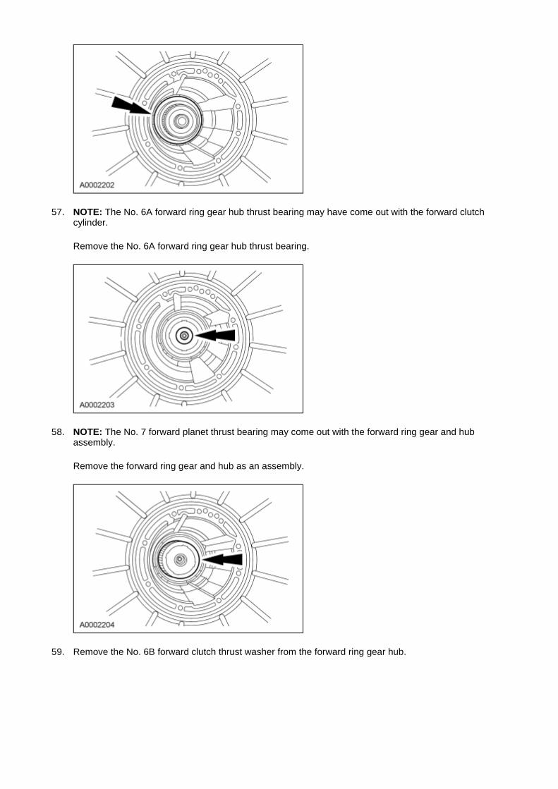
57. NOTE: The No. 6A forward ring gear hub thrust bearing may have come out with the forward clutch cylinder.
Remove the No. 6A forward ring gear hub thrust bearing.
58. NOTE: The No. 7 forward planet thrust bearing may come out with the forward ring gear and hub assembly.
Remove the forward ring gear and hub as an assembly.
59. Remove the No. 6B forward clutch thrust washer from the forward ring gear hub.
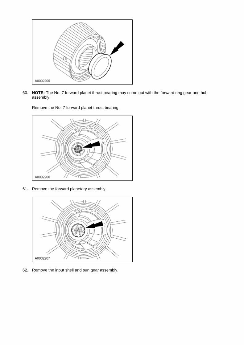
60. NOTE: The No. 7 forward planet thrust bearing may come out with the forward ring gear and hub assembly.
Remove the No. 7 forward planet thrust bearing.
61. Remove the forward planetary assembly.
62. Remove the input shell and sun gear assembly.
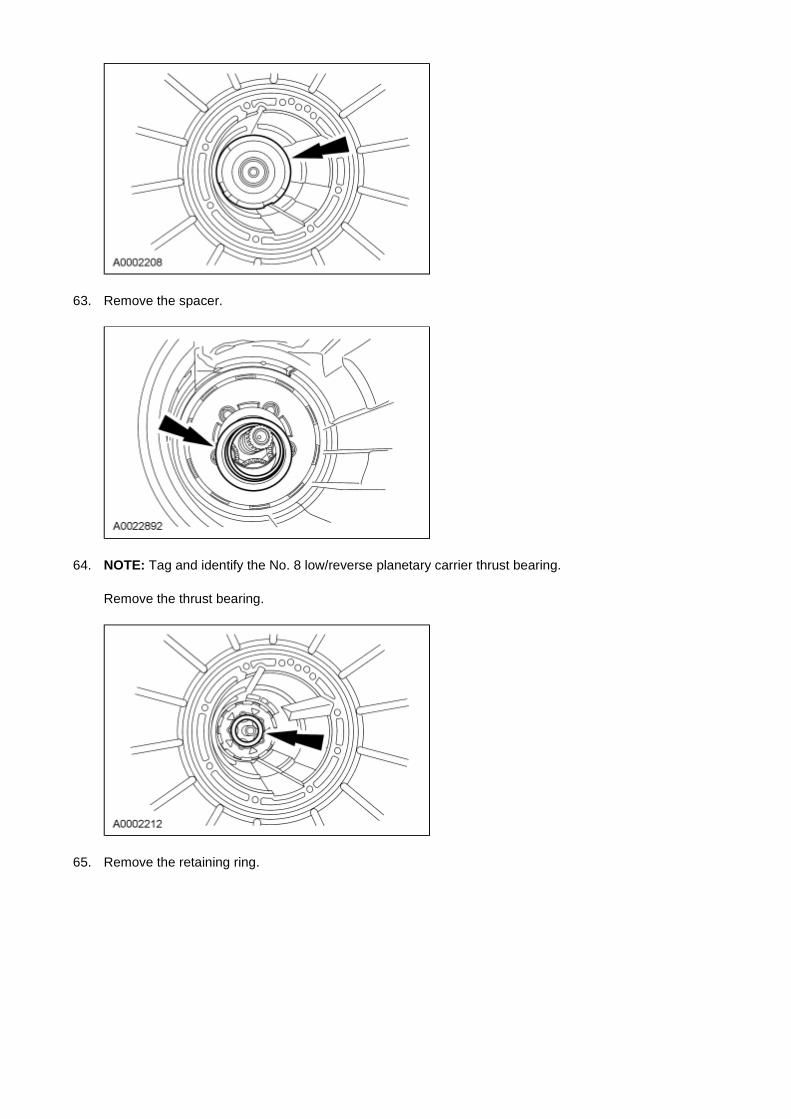
63. Remove the spacer.
64. NOTE: Tag and identify the No. 8 low/reverse planetary carrier thrust bearing.
Remove the thrust bearing.
65. Remove the retaining ring.
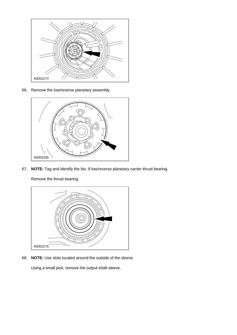
66. Remove the low/reverse planetary assembly.
67. NOTE: Tag and identify the No. 9 low/reverse planetary carrier thrust bearing.
Remove the thrust bearing.
68. NOTE: Use slots located around the outside of the sleeve.
Using a small pick, remove the output shaft sleeve.

69. WARNING: Hold onto the output shaft so it does not fall out after removing the snap ring. Failure to follow this instruction may result in serious personal injury.
NOTICE: Discard the output shaft retaining ring. A new retaining ring must be used for assembly, otherwise transmission damage can occur.
While holding the output shaft, remove and discard the output shaft retaining ring.
70. Remove the output shaft ring gear and hub.
71. Remove the No. 10 low/intermediate sun gear bearing.
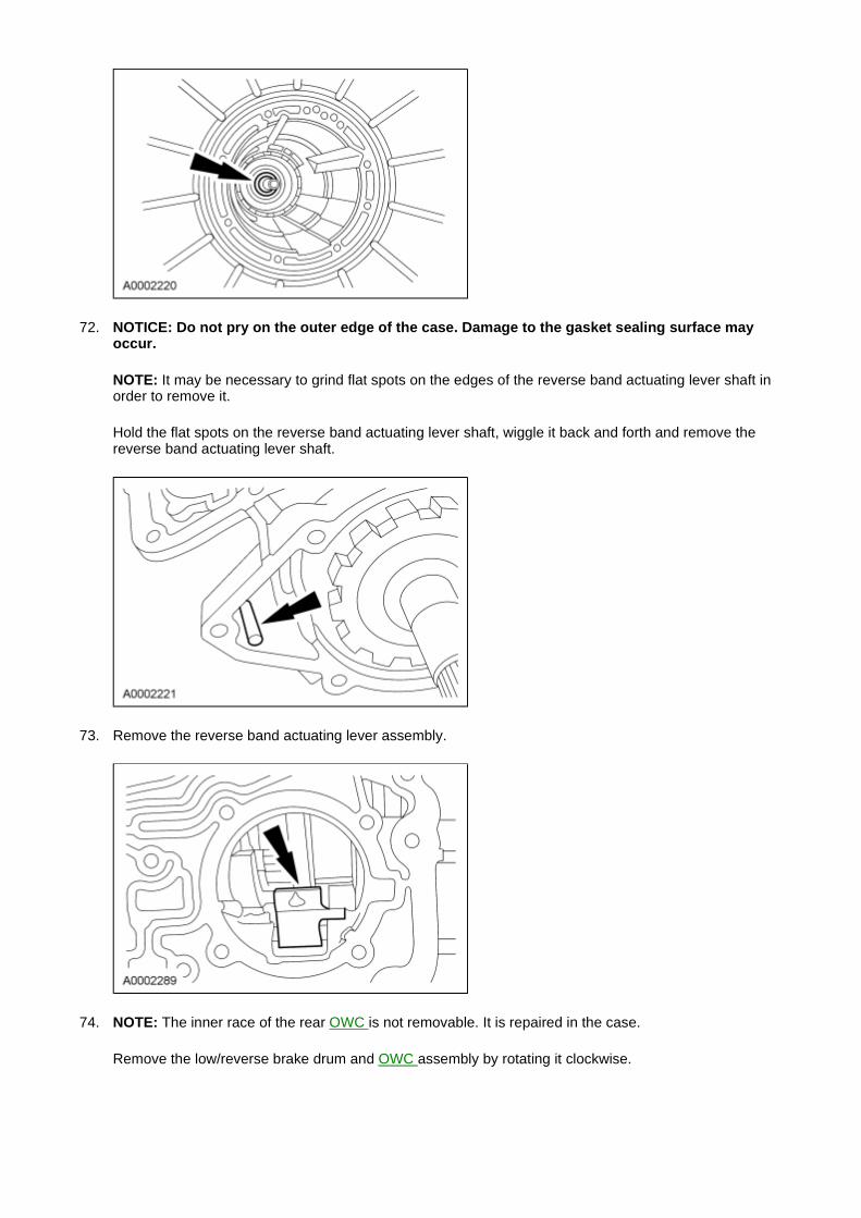
72. NOTICE: Do not pry on the outer edge of the case. Damage to the gasket sealing surface may occur.
NOTE: It may be necessary to grind flat spots on the edges of the reverse band actuating lever shaft in order to remove it.
Hold the flat spots on the reverse band actuating lever shaft, wiggle it back and forth and remove the reverse band actuating lever shaft.
73. Remove the reverse band actuating lever assembly.
74. NOTE: The inner race of the rear OWC is not removable. It is repaired in the case.
Remove the low/reverse brake drum and OWC assembly by rotating it clockwise.
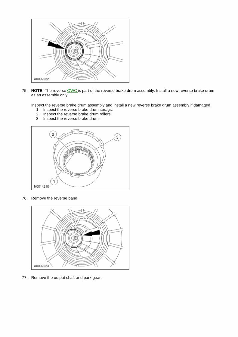
75. NOTE: The reverse OWC is part of the reverse brake drum assembly. Install a new reverse brake drum as an assembly only.
Inspect the reverse brake drum assembly and install a new reverse brake drum assembly if damaged. 1. Inspect the reverse brake drum sprags. 2. Inspect the reverse brake drum rollers. 3. Inspect the reverse brake drum.
76. Remove the reverse band.
77. Remove the output shaft and park gear.
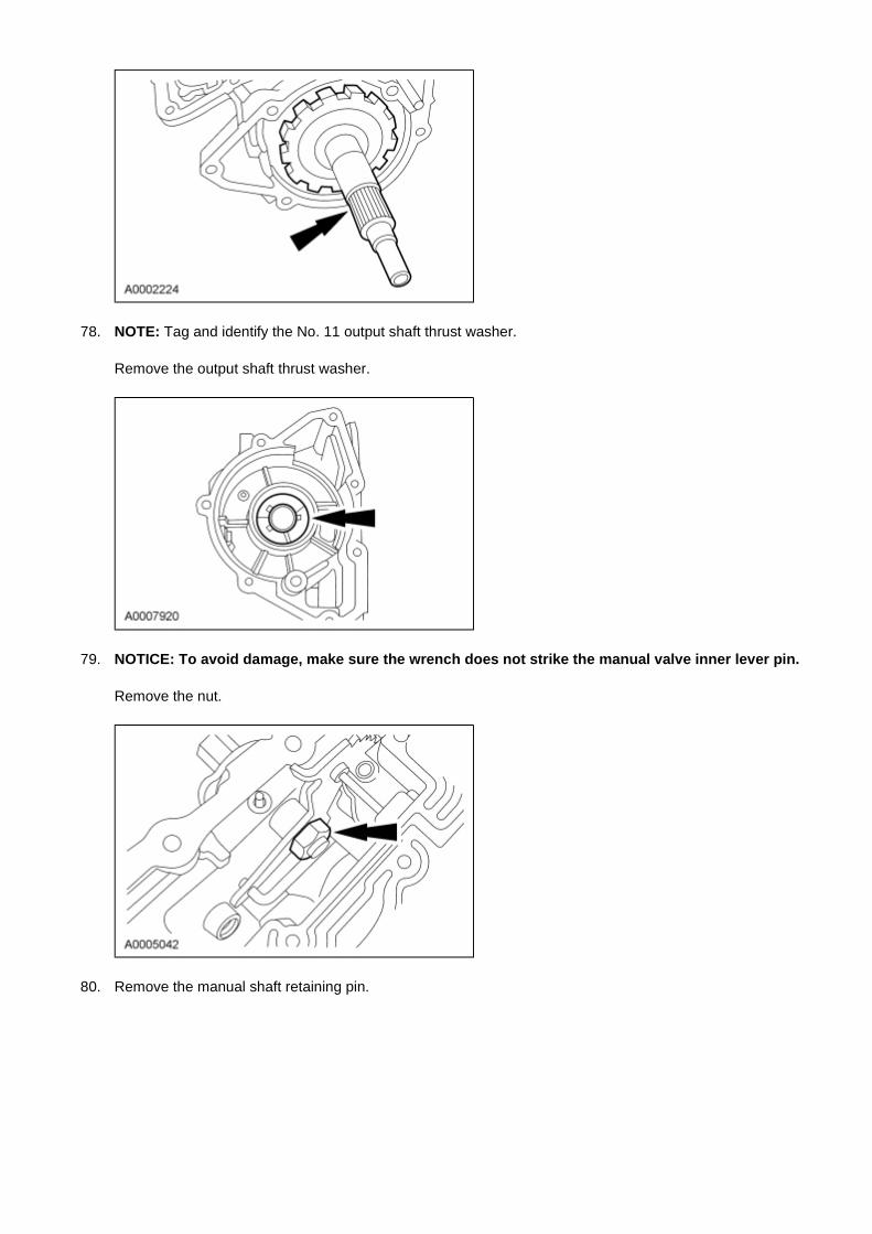
78. NOTE: Tag and identify the No. 11 output shaft thrust washer.
Remove the output shaft thrust washer.
79. NOTICE: To avoid damage, make sure the wrench does not strike the manual valve inner lever pin.
Remove the nut.
80. Remove the manual shaft retaining pin.
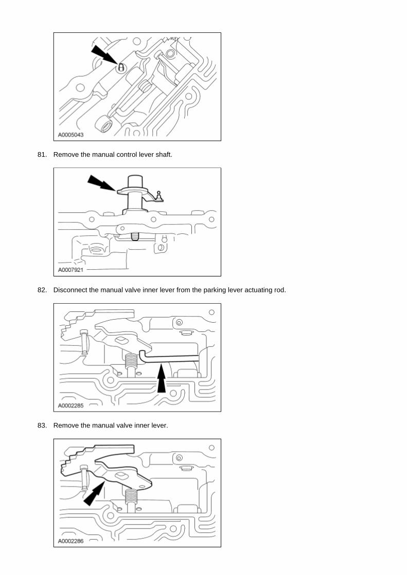
81. Remove the manual control lever shaft.
82. Disconnect the manual valve inner lever from the parking lever actuating rod.
83. Remove the manual valve inner lever.
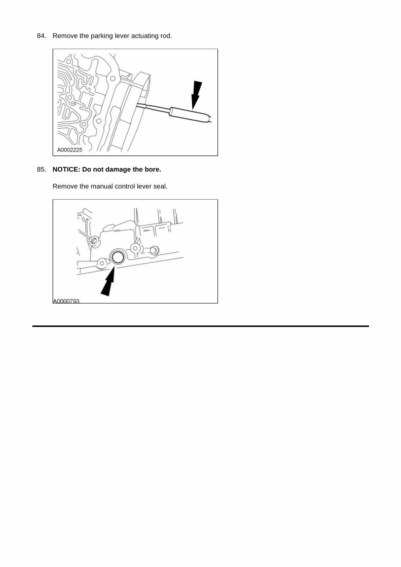
84. Remove the parking lever actuating rod.
85. NOTICE: Do not damage the bore.
Remove the manual control lever seal.


![Automatic Transaxle (Service) [Gf4ax-El]](https://static.fdocuments.net/doc/165x107/55cf8547550346484b8c4943/automatic-transaxle-service-gf4ax-el.jpg)