Transitioning the tactical Marine Corps to IPv6 · PDF fileTransitioning the tactical Marine...
52
Calhoun: The NPS Institutional Archive Theses and Dissertations Thesis Collection 2011-09 Transitioning the tactical Marine Corps to IPv6 Fodera, Christopher M. Monterey, California. Naval Postgraduate School http://hdl.handle.net/10945/5602
Transcript of Transitioning the tactical Marine Corps to IPv6 · PDF fileTransitioning the tactical Marine...
Calhoun: The NPS Institutional Archive
Theses and Dissertations Thesis Collection
2011-09
Transitioning the tactical Marine Corps to IPv6
Fodera, Christopher M.
Monterey, California. Naval Postgraduate School
http://hdl.handle.net/10945/5602
NAVAL
POSTGRADUATE SCHOOL
MONTEREY, CALIFORNIA
THESIS
Approved for public release; distribution is unlimited
TRANSITIONING THE TACTICAL MARINE CORPS TO IPv6
by
Christopher M. Fodera
September 2011
Thesis Advisor: Alex Bordetsky Second Reader: David Cabrera

THIS PAGE INTENTIONALLY LEFT BLANK
i
REPORT DOCUMENTATION PAGE Form Approved OMB No. 0704–0188Public reporting burden for this collection of information is estimated to average 1 hour per response, including the time for reviewing instruction, searching existing data sources, gathering and maintaining the data needed, and completing and reviewing the collection of information. Send comments regarding this burden estimate or any other aspect of this collection of information, including suggestions for reducing this burden, to Washington headquarters Services, Directorate for Information Operations and Reports, 1215 Jefferson Davis Highway, Suite 1204, Arlington, VA 22202–4302, and to the Office of Management and Budget, Paperwork Reduction Project (0704–0188) Washington DC 20503. 1. AGENCY USE ONLY (Leave blank)
2. REPORT DATE September 2011
3. REPORT TYPE AND DATES COVERED Master’s Thesis
4. TITLE AND SUBTITLE: Transitioning the Tactical Marine Corps to IPv6 5. FUNDING NUMBERS
6. AUTHOR: Christopher M. Fodera
7. PERFORMING ORGANIZATION NAME(S) AND ADDRESS(ES)Naval Postgraduate School Monterey, CA 93943–5000
8. PERFORMING ORGANIZATION REPORT NUMBER
9. SPONSORING /MONITORING AGENCY NAME(S) AND ADDRESS(ES)N/A
10. SPONSORING/MONITORING AGENCY REPORT NUMBER
11. SUPPLEMENTARY NOTES The views expressed in this thesis are those of the author and do not reflect the official policy or position of the Department of Defense or the U.S. Government. IRB Protocol Number: NA. 12a. DISTRIBUTION / AVAILABILITY STATEMENT Approved for public release; distribution is unlimited
12b. DISTRIBUTION CODE
13. ABSTRACT (maximum 200 words) As communication in tactical arenas continues to trend from serial to Internet Protocol (IP) based, the necessity for tactical programs of record to embrace IP communications becomes more and more imperative. While many Marine Corps tactical communications programs of record already recognize this trend and its significance, some are affected more heavily than others.
Numerous advantages exist for transitioning from Internet Protocol version 4 to Internet Protocol version 6, and a top-down transition makes most sense for deployed and deploying units; the Data Distribution System-Modular is the system best suited to take on this role. The Naval Postgraduate School’s Center for Network Innovation and Experimentation (CENETIX) and Tactical Network Topology (TNT) field experimentation program, along with the Marine Corps Tactical Systems Support Activity (MCTSSA), can take on this task of transitioning the Tactical Marine Corps to IPv6; the commonality of the Defense Research Engineering Network (DREN) will allow for collaboration and testing that will greatly benefit our war fighters. 14. SUBJECT TERMS: IPv6, Transition, DDS-M, Tactical Networking 15. NUMBER OF
PAGES 51
16. PRICE CODE
17. SECURITY CLASSIFICATION OF REPORT
Unclassified
18. SECURITY CLASSIFICATION OF THIS PAGE
Unclassified
19. SECURITY CLASSIFICATION OF ABSTRACT
Unclassified
20. LIMITATION OF ABSTRACT
UU NSN 7540–01–280–5500 Standard Form 298 (Rev. 8–98) Prescribed by ANSI Std. Z39.18

ii
THIS PAGE INTENTIONALLY LEFT BLANK
iii
Approved for public release; distribution is unlimited
TRANSITIONING THE TACTICAL MARINE CORPS TO IPv6
Christopher M. Fodera Captain, United States Marine Corps
B.S., United States Naval Academy, 2002
Submitted in partial fulfillment of the requirements for the degree of
MASTER OF SCIENCE IN INFORMATION TECHNOLOGY MANAGEMENT
from the
NAVAL POSTGRADUATE SCHOOL September 2011
Author: Christopher M. Fodera
Approved by: Dr. Alex Bordetsky Thesis Advisor
CWO4 David Cabrera, USMC Second Reader
Dr. Dan Boger Chair, Department of Information Sciences

iv
THIS PAGE INTENTIONALLY LEFT BLANK
v
ABSTRACT
As communication in tactical arenas continues to trend from serial to Internet
Protocol (IP) based, the necessity for tactical programs of record to embrace IP
communications becomes more and more imperative. While many Marine Corps
tactical communications programs of record already recognize this trend and its
significance, some are affected more heavily than others.
Numerous advantages exist for transitioning from Internet Protocol version
4 to Internet Protocol version 6, and a top-down transition makes most sense for
deployed and deploying units; the Data Distribution System-Modular is the
system best suited to take on this role.
The Naval Postgraduate School’s Center for Network Innovation and
Experimentation (CENETIX) and Tactical Network Topology (TNT) field
experimentation program, along with the Marine Corps Tactical Systems Support
Activity (MCTSSA), can take on this task of transitioning the Tactical Marine
Corps to IPv6; the commonality of the Defense Research Engineering Network
(DREN) will allow for collaboration and testing that will greatly benefit our war
fighters.

vi
THIS PAGE INTENTIONALLY LEFT BLANK
vii
TABLE OF CONTENTS
I. INTRODUCTION ............................................................................................. 1 A. BACKGROUND ................................................................................... 1
1. The DDS-M ................................................................................ 1 2. The Protocols Compared ........................................................ 3
B. PURPOSE OF STUDY ......................................................................... 4 C. TEST OBJECTIVES ............................................................................. 5 D. TEST SCOPE ....................................................................................... 5 E. TEST CONSTRAINTS ......................................................................... 5
II. TEST ENVIRONMENT.................................................................................... 7 A. TEST LOCATION ................................................................................. 7 B. TEST CONFIGURATION ..................................................................... 7 C. PARTICIPATING SYSTEMS ............................................................... 8
1. System Under Test .................................................................. 9 2. Other Participating Systems ................................................. 10
a. VSAT-L ......................................................................... 10 b. DREN ............................................................................ 10
3. Simulation/Stimulation Tools ............................................... 11 a. Spirent .......................................................................... 11 b. Ixia ................................................................................ 11 c. BreakingPoint .............................................................. 12
4. Data Collection/Analysis Tools ............................................ 13 a. NetScout ...................................................................... 13 b. WireShark .................................................................... 13 c. Riverbed Cascade Pilot .............................................. 13
D. PHYSICAL TEST ENVIRONMENT LAYOUT .................................... 14 E. SECURITY ......................................................................................... 15 F. DETAILED TEST ARCHITECTURE .................................................. 16
III. TEST DESIGN .............................................................................................. 17 A. OVERALL TEST APPROACH ........................................................... 17 B. PLANNED TESTS .............................................................................. 18
1. Phase 1: Performance ........................................................... 19 a. Scenario 1 .................................................................... 20 b. Scenario 2 .................................................................... 21 c. Scenario 3 .................................................................... 21
2. Phase 2: Conformance .......................................................... 26 3. Phase 3: Security ................................................................... 26 4. Phase 4: Interoperability ....................................................... 26
C. EVALUATION CRITERIA .................................................................. 27 D. PROBLEM REPORTING ................................................................... 27 E. SUSPENSION CRITERIA AND RESUMPTION REQUIREMENTS ... 28 F. TEST SCHEDULE .............................................................................. 28

viii
IV. CONCLUSION AND RECOMMENDATIONS ............................................... 29 A. FUTURE WORK AT MCTSSA ........................................................... 29
1. The Foundation has been Laid ............................................. 29 2. The Need for an IPv6 Lead .................................................... 29
BIBLIOGRAPHY ..................................................................................................... 31
INITIAL DISTRIBUTION LIST ................................................................................. 33
ix
LIST OF FIGURES
Figure 1. DDS-M .................................................................................................. 2 Figure 2. IPv4 and IPv6 Headers Compared ....................................................... 4 Figure 3. High Level Test Diagram ...................................................................... 7 Figure 4. Physical Test Environment Layout ..................................................... 15 Figure 5. Network Diagram ................................................................................ 16

x
THIS PAGE INTENTIONALLY LEFT BLANK
xi
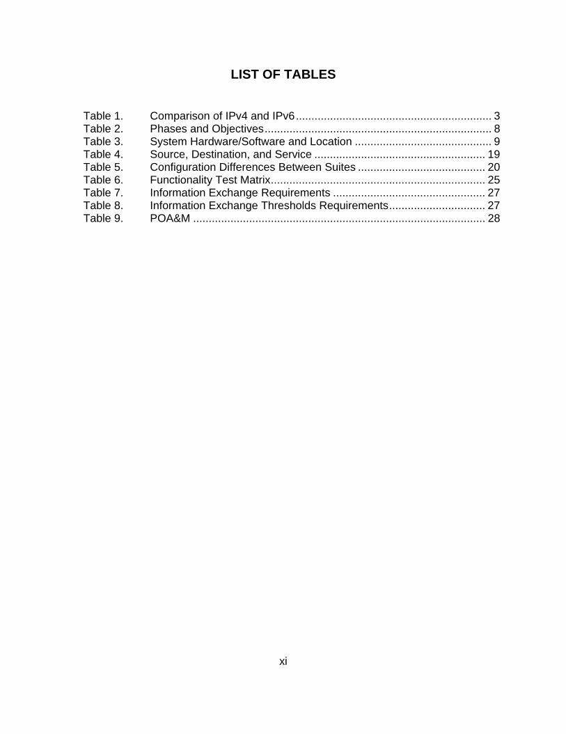
LIST OF TABLES
Table 1. Comparison of IPv4 and IPv6 ............................................................... 3 Table 2. Phases and Objectives ......................................................................... 8 Table 3. System Hardware/Software and Location ............................................ 9 Table 4. Source, Destination, and Service ....................................................... 19 Table 5. Configuration Differences Between Suites ......................................... 20 Table 6. Functionality Test Matrix ..................................................................... 25 Table 7. Information Exchange Requirements ................................................. 27 Table 8. Information Exchange Thresholds Requirements ............................... 27 Table 9. POA&M .............................................................................................. 28

xii
THIS PAGE INTENTIONALLY LEFT BLANK
xiii
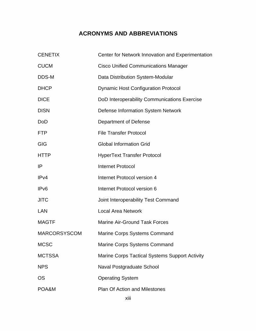
ACRONYMS AND ABBREVIATIONS
CENETIX Center for Network Innovation and Experimentation
CUCM Cisco Unified Communications Manager
DDS-M Data Distribution System-Modular
DHCP Dynamic Host Configuration Protocol
DICE DoD Interoperability Communications Exercise
DISN Defense Information System Network
DoD Department of Defense
FTP File Transfer Protocol
GIG Global Information Grid
HTTP HyperText Transfer Protocol
IP Internet Protocol
IPv4 Internet Protocol version 4
IPv6 Internet Protocol version 6
JITC Joint Interoperability Test Command
LAN Local Area Network
MAGTF Marine Air-Ground Task Forces
MARCORSYSCOM Marine Corps Systems Command
MCSC Marine Corps Systems Command
MCTSSA Marine Corps Tactical Systems Support Activity
NPS Naval Postgraduate School
OS Operating System
POA&M Plan Of Action and Milestones
xiv
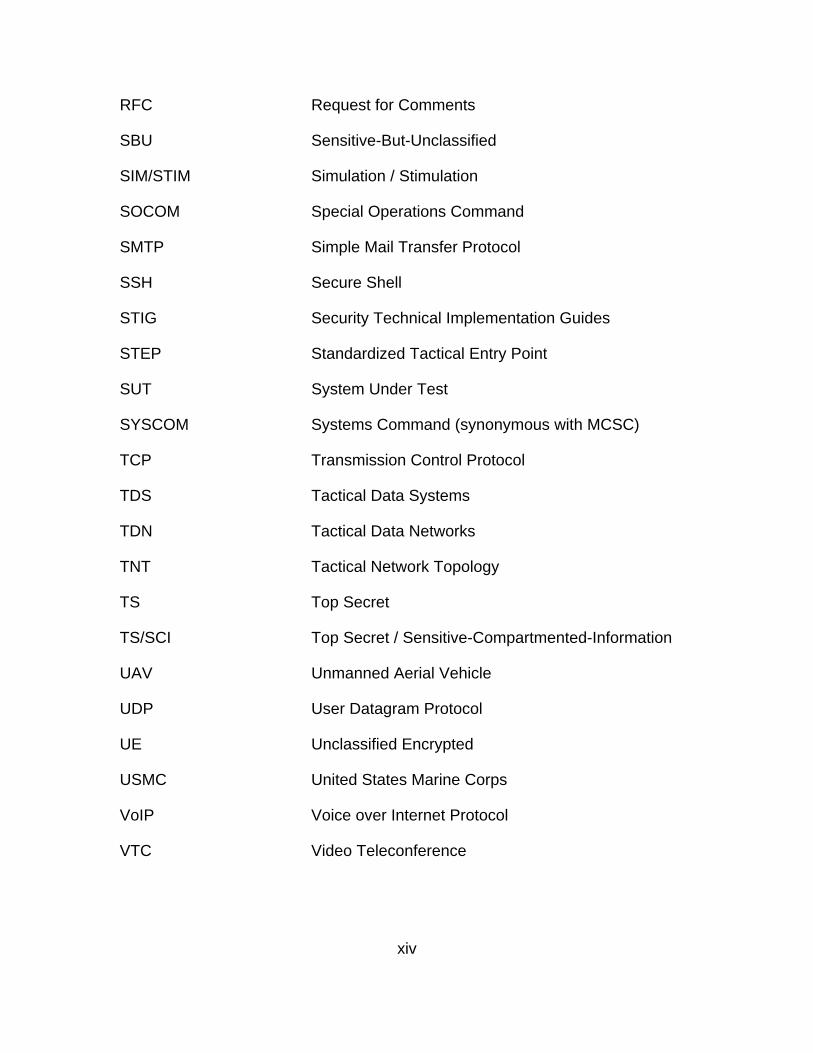
RFC Request for Comments
SBU Sensitive-But-Unclassified
SIM/STIM Simulation / Stimulation
SOCOM Special Operations Command
SMTP Simple Mail Transfer Protocol
SSH Secure Shell
STIG Security Technical Implementation Guides
STEP Standardized Tactical Entry Point
SUT System Under Test
SYSCOM Systems Command (synonymous with MCSC)
TCP Transmission Control Protocol
TDS Tactical Data Systems
TDN Tactical Data Networks
TNT Tactical Network Topology
TS Top Secret
TS/SCI Top Secret / Sensitive-Compartmented-Information
UAV Unmanned Aerial Vehicle
UDP User Datagram Protocol
UE Unclassified Encrypted
USMC United States Marine Corps
VoIP Voice over Internet Protocol
VTC Video Teleconference

xv
ACKNOWLEDGMENTS
To my wife, Andrea, thank you for your constant support and never-ending
patience. Your love for our wonderful children and me is inspirational; being with
you all is the most important thing in my life.
Dave Cabrera’s constructive criticism and general wealth of knowledge
made him an easy pick as a second reader. I learned to trust Dave implicitly
while deployed and like always, he has never steered my wrong. Paul Nyenhuis
has been invaluable in the vision and scope of this effort. I would also like to
thank Doctor Alex Bordetsky for his vision on this thesis.

xvi
THIS PAGE INTENTIONALLY LEFT BLANK
1
I. INTRODUCTION
A. BACKGROUND
1. The DDS-M
The Tactical Data Networks (TDN) Project Officer at Marine Corps
Systems Command (MCSC) identified the need for interoperability assessments
on the Data Distribution System-Modular (DDS-M). The results of these
assessments will determine the extent of joint interoperability for the DDS-M
when transitioning from Internet Protocol version 4 (IPv4) to Internet Protocol
version 6 (IPv6).
The DDS-M was previously tested for interoperability by Joint
Interoperability Test Command (JITC), but IPv6 testing was not completed.
Specific protocols tested include: HTTP, FTP, SMTP, VoIP, and VTC IPv6
requirements. Follow-on participation will allow additional IPv6 testing to continue
and address previously identified shortfalls.
The Marine Corps deploys Marine Air-Ground Task Forces (MAGTFs)
throughout the world to fulfill operational requirements, often in joint/combined
operating environments. During these deployments, MAGTFs require access to
strategic, theater, and tactical communications networks and information systems
that support functional capabilities for command, control, communications,
administration, logistics and intelligence. TDN DDS is the data communications
backbone for the MAGTF augmenting and extending Defense Information
System Network (DISN) services.
The DDS-M was developed to support the MAGTF command and control
communications mission objectives. It was designed to provide Internet Protocol
(IP) based data routing, information processing and storage, as well as network
extension capabilities for deployed Marine Corps forces. The DDS-M features a
flexible and modular Local Area Network (LAN) capability to provide services to
the Marine Corps Tactical Data Systems (TDS) and other DDS-M systems. The
2
DDS-M can function as the file server supporting typical LAN services such as
file sharing and electronic mail. A DDS-M suite also has the switching,
processing, and storage capacity, along with the flexibility to support operations
at a single security level.
A DDS-M suite can operate from the Sensitive-But-Unclassified (SBU) up
to the Top Secret (TS)/Sensitive-Compartmented-Information (SCI) level and will
contain an integral Inline Network Encryption (INE) device to support tunneling.
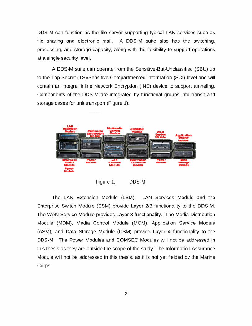
Components of the DDS-M are integrated by functional groups into transit and
storage cases for unit transport (Figure 1).
Figure 1. DDS-M
The LAN Extension Module (LSM), LAN Services Module and the
Enterprise Switch Module (ESM) provide Layer 2/3 functionality to the DDS-M.
The WAN Service Module provides Layer 3 functionality. The Media Distribution
Module (MDM), Media Control Module (MCM), Application Service Module
(ASM), and Data Storage Module (DSM) provide Layer 4 functionality to the
DDS-M. The Power Modules and COMSEC Modules will not be addressed in
this thesis as they are outside the scope of the study. The Information Assurance
Module will not be addressed in this thesis, as it is not yet fielded by the Marine
Corps.
3
2. The Protocols Compared
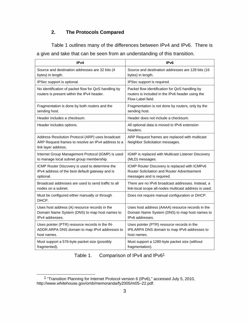
Table 1 outlines many of the differences between IPv4 and IPv6. There is
a give and take that can be seen from an understanding of this transition.
IPv4 IPv6
Source and destination addresses are 32 bits (4 bytes) in length.
Source and destination addresses are 128 bits (16 bytes) in length.
IPSec support is optional. IPSec support is required.
No identification of packet flow for QoS handling by routers is present within the IPv4 header.
Packet flow identification for QoS handling by routers is included in the IPv6 header using the Flow Label field.
Fragmentation is done by both routers and the sending host.
Fragmentation is not done by routers, only by the sending host.
Header includes a checksum. Header does not include a checksum.
Header includes options. All optional data is moved to IPv6 extension headers.
Address Resolution Protocol (ARP) uses broadcast ARP Request frames to resolve an IPv4 address to a link layer address.
ARP Request frames are replaced with multicast Neighbor Solicitation messages.
Internet Group Management Protocol (IGMP) is used to manage local subnet group membership.
IGMP is replaced with Multicast Listener Discovery (MLD) messages.
ICMP Router Discovery is used to determine the IPv4 address of the best default gateway and is optional.
ICMP Router Discovery is replaced with ICMPv6 Router Solicitation and Router Advertisement messages and is required.
Broadcast addresses are used to send traffic to all nodes on a subnet.
There are no IPv6 broadcast addresses. Instead, a link-local scope all-nodes multicast address is used.
Must be configured either manually or through DHCP.
Does not require manual configuration or DHCP.
Uses host address (A) resource records in the Domain Name System (DNS) to map host names to IPv4 addresses.
Uses host address (AAAA) resource records in the Domain Name System (DNS) to map host names to IPv6 addresses.
Uses pointer (PTR) resource records in the IN-ADDR.ARPA DNS domain to map IPv4 addresses to host names.
Uses pointer (PTR) resource records in the IP6.ARPA DNS domain to map IPv6 addresses to host names.
Must support a 576-byte packet size (possibly fragmented).
Must support a 1280-byte packet size (without fragmentation).
Table 1. Comparison of IPv4 and IPv61
1 “Transition Planning for Internet Protocol version 6 (IPv6),” accessed July 5, 2010,
http://www.whitehouse.gov/omb/memoranda/fy2005/m05–22.pdf.
4
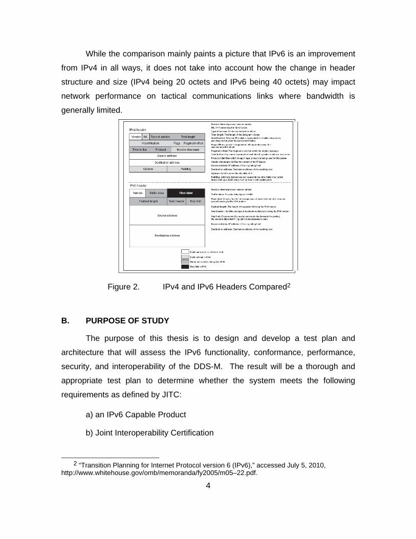
While the comparison mainly paints a picture that IPv6 is an improvement
from IPv4 in all ways, it does not take into account how the change in header
structure and size (IPv4 being 20 octets and IPv6 being 40 octets) may impact
network performance on tactical communications links where bandwidth is
generally limited.
Figure 2. IPv4 and IPv6 Headers Compared2
B. PURPOSE OF STUDY
The purpose of this thesis is to design and develop a test plan and
architecture that will assess the IPv6 functionality, conformance, performance,
security, and interoperability of the DDS-M. The result will be a thorough and
appropriate test plan to determine whether the system meets the following
requirements as defined by JITC:
a) an IPv6 Capable Product
b) Joint Interoperability Certification
2 “Transition Planning for Internet Protocol version 6 (IPv6),” accessed July 5, 2010,
http://www.whitehouse.gov/omb/memoranda/fy2005/m05–22.pdf.
5
C. TEST OBJECTIVES
The objectives of the test will be to verify/demonstrate the interoperability
of DDS-M in a Joint Environment when transitioned from IPv4 to IPv6 in the
following areas:
1. IPv6 functionality
2. IPv6 conformance
3. IPv6 performance
4. IPv6 security
D. TEST SCOPE
The testing will encompass various aspects of the system and
components. The system is comprised of multiple components that fall into
different IPv6 Product Classes, as defined in the DoD IPv6 Standard Profiles for
IPv6 Capable Products version 6.0. Each of these product classes have unique
mandatory and optional requirements and will be evaluated separately. The test
will be an iterative process to accurately evaluate both the individual components
and the system in its entirety.
The test is divided into four phases. The focus of Phase 1 is to assess
functionality and performance of IPv6 applications, services, transport and
routing. This phase will test three network scenarios; IPv4, dual-stack, and IPv6
native. The focus of Phase 2 is to assess conformance of individual system
components. Phase 3 will assess security aspects of IPv6 products. Phase 4 is
interoperability testing; during this phase, information exchanges for voice, video,
and data will be assessed in unclassified and unclassified encrypted networks.
E. TEST CONSTRAINTS
The test will be conducted on a closed network between MCTSSA and
JITC; thus, there will be no connection to the Internet or any other networks.
MCTSSA must rely on JITC’s ability to emulate the required network and

6
services expected for IPv6 testing. Specific tests that cannot be supported will
be executed in the IPv6 lab at MCTSSA. Areas untested will be deferred to later
events.
7
II. TEST ENVIRONMENT
A. TEST LOCATION
The IPv6 test will take place at MCTSSA aboard Camp Pendleton,
California, with Defense Research Engineering Network (DREN) or Satellite
connectivity to JITC’s simulated Standardized Tactical Entry Point (STEP) at Fort
Huachuca, Arizona. Aboard MCTSSA, the systems under test will be located in
Bldg-31357 lab and in the Communications (Comm) Node shelter, located on the
south side of Bldg-31357. Transmission systems will be located in the lot north
of Bldg-313059.
B. TEST CONFIGURATION
The IPv6 test will be conducted as part of Department of Defense (DoD)
Interoperability Communications Exercise (DICE) and participating systems will
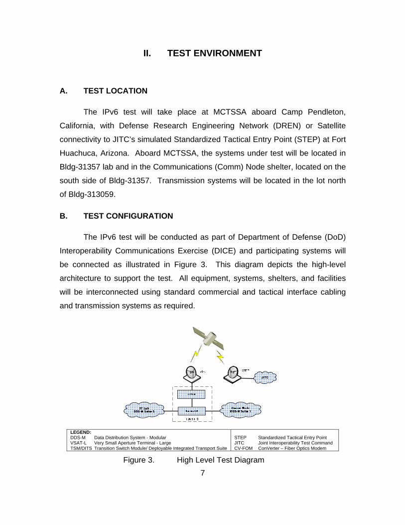
be connected as illustrated in Figure 3. This diagram depicts the high-level
architecture to support the test. All equipment, systems, shelters, and facilities
will be interconnected using standard commercial and tactical interface cabling
and transmission systems as required.
LEGEND: DDS-M Data Distribution System - Modular VSAT-L Very Small Aperture Terminal - Large TSM/DITS Transition Switch Module/ Deployable Integrated Transport Suite
STEP Standardized Tactical Entry Point JITC Joint Interoperability Test Command CV-FOM ConVerter – Fiber Optics Modem
Figure 3. High Level Test Diagram
8
The two suites (1 and 2) depicted in Figure 3 will be configured uniquely to
support the different scenarios and phases of testing in order to reduce the
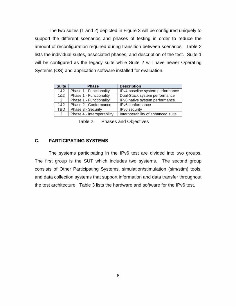
amount of reconfiguration required during transition between scenarios. Table 2
lists the individual suites, associated phases, and description of the test. Suite 1
will be configured as the legacy suite while Suite 2 will have newer Operating
Systems (OS) and application software installed for evaluation.
Suite Phase Description 1&2 Phase 1 - Functionality IPv4 baseline system performance 1&2 Phase 1 - Functionality Dual-Stack system performance
2 Phase 1 - Functionality IPv6 native system performance 1&2 Phase 2 - Conformance IPv6 conformance TBD Phase 3 - Security IPv6 security
2 Phase 4 - Interoperability Interoperability of enhanced suite
Table 2. Phases and Objectives
C. PARTICIPATING SYSTEMS
The systems participating in the IPv6 test are divided into two groups.
The first group is the SUT which includes two systems. The second group
consists of Other Participating Systems, simulation/stimulation (sim/stim) tools,
and data collection systems that support information and data transfer throughout
the test architecture. Table 3 lists the hardware and software for the IPv6 test.
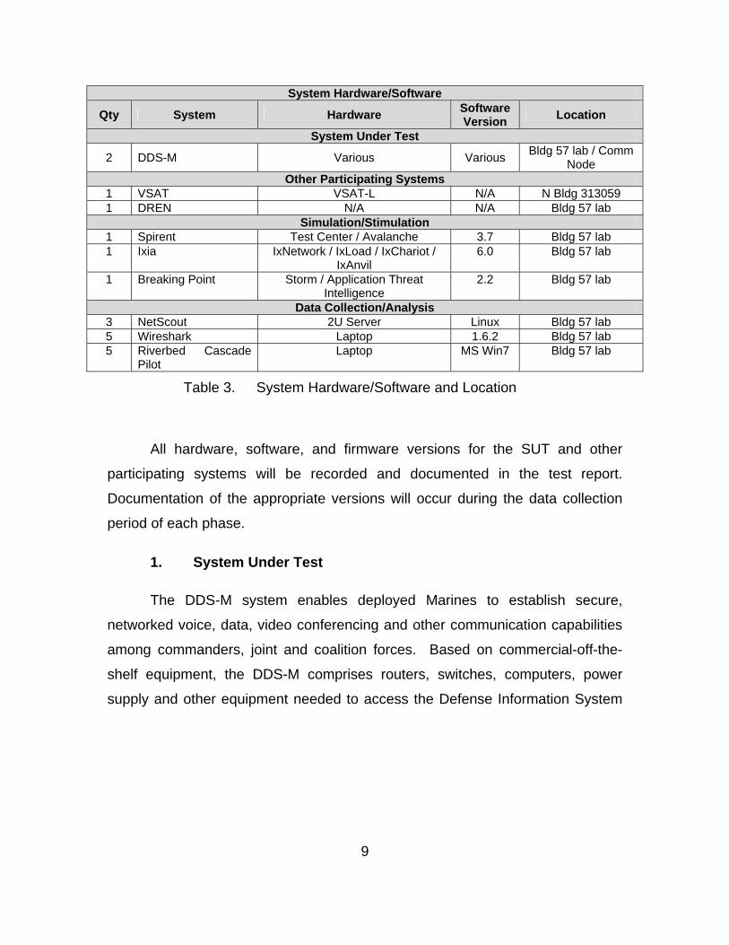
9
System Hardware/Software
Qty System Hardware Software Version
Location
System Under Test
2 DDS-M Various Various Bldg 57 lab / Comm
Node Other Participating Systems
1 VSAT VSAT-L N/A N Bldg 313059 1 DREN N/A N/A Bldg 57 lab
Simulation/Stimulation 1 Spirent Test Center / Avalanche 3.7 Bldg 57 lab 1 Ixia IxNetwork / IxLoad / IxChariot /
IxAnvil 6.0 Bldg 57 lab
1 Breaking Point Storm / Application Threat Intelligence
2.2 Bldg 57 lab
Data Collection/Analysis 3 NetScout 2U Server Linux Bldg 57 lab 5 Wireshark Laptop 1.6.2 Bldg 57 lab 5 Riverbed Cascade
Pilot Laptop MS Win7 Bldg 57 lab
Table 3. System Hardware/Software and Location
All hardware, software, and firmware versions for the SUT and other
participating systems will be recorded and documented in the test report.
Documentation of the appropriate versions will occur during the data collection
period of each phase.
1. System Under Test
The DDS-M system enables deployed Marines to establish secure,
networked voice, data, video conferencing and other communication capabilities
among commanders, joint and coalition forces. Based on commercial-off-the-
shelf equipment, the DDS-M comprises routers, switches, computers, power
supply and other equipment needed to access the Defense Information System
10
Network (DISN), Secret Internet Protocol Router Network (SIPRNet) and Non-
secure Internet Protocol Router Network (NIPRNet), as well as coalition and
joint-forces networks.3
2. Other Participating Systems
a. VSAT-L
The purpose of the SWAN-D/VSAT is to enable USMC intra-theater
communications; to allow forward deployed elements to “break” the terrestrial
line-of-sight tether and extend their operations farther from their higher echelon
command or to enable operations in terrain not conducive to Line-of-sight (LOS)
operations.4
b. DREN
The Defense Research and Engineering Network (DREN) is DoD’s
recognized research and engineering network. The DREN is a robust, high-
capacity, low-latency nation-wide network that provides connectivity between and
among the HPCMP’s geographically dispersed High Performance Computing
(HPC) user sites, HPC Centers, and other networks. The DREN provides digital,
imaging, video, and audio data transfer services between defined service
delivery points (SDPs). SDPs are specified in terms of WAN bandwidth access,
supported network protocols [Multi Protocol Label Switching, Internet Protocol
(IP), Asynchronous Transfer Mode (ATM)], and local connection interfaces.
3 “General Dynamics Awarded $130 Million Contract to Produce Tactical Data Network
Systems for the U.S. Marine Corps,” accessed Aug 6, 2011, http://www.gdc4s.com/news/detail.cfm?prid=285.
4 “2010 SWAN Fact Sheet,” accessed Aug 6, 2011, http://www.marcorsyscom.usmc.mil/sites/cins/Fact%20Books/NSC/SATCOM/2010%20SWAN%20Fact%20Sheet.pdf.
11
DREN currently supports both IP version 4 (IPv4) and IP version 6 (IPv6) at
bandwidths from DS-3 (45 Mbps) at user sites up to OC-48c (2.488Gbps) at
selected HPC Centers.5
3. Simulation/Stimulation Tools
a. Spirent
Spirent’s Test Center is an application of high scale, realistic traffic
ensures that networks and components are evaluated accurately and proven to
perform as services scale.6 Avalanche is a line rate, 1 Gbps and 10Gbps Layer
4–7 multi-protocol stateful traffic performance solution that is capable multi
10Gbps of stateful application traffic generation.7
b. Ixia
IxNetwork is designed to test network infrastructure, capacity,
scalability, and convergence providing rapid isolation of network issues, service
modeling at Internet scale, carrier class scaling, and accurate convergence
measurement.8
IxLoad is a scalable solution for testing converged multiplay
services, application delivery platforms, and security devices and systems.
IxLoad emulates data, voice, and video subscribers and associated protocols to
ensure quality of experience (QoE). IxLoad also applies malware and distributed
denial of service (DDoS) attacks for security effectiveness and accuracy testing.9
5 “Defense Research and Engineering Network Definition,” accessed Aug 6, 2011,
http://www.hpcmo.hpc.mil/Htdocs/DREN/dren-def.html.
6 “Spirent Test Center,” accessed Aug 6, 2011, http://www.spirent.com/Solutions-Directory/Spirent-TestCenter.aspx.
7 “Avalanche,” accessed Aug 6, 2011, http://www.spirent.com/Solutions-Directory/Avalanche.aspx.
8 “IxNetwork for Network Topology Testing and Traffic Analysis,” accessed Aug 6, 2011, http://www.ixiacom.com/products/ixnetwork/index.php.
9 “IxLoad: Overview,” accessed Aug 6, 2011, http://www.ixiacom.com/products/ixload/index.php.
12
IxChariot is Ixia’s network assessment tool for troubleshooting
networks and applications; it allows for simulation of real-world applications to
predict device and system performance under realistic load conditions.10 IxANVL
(Automated Network Validation Library) is Ixia’s solution for automated
network/protocol validation.11
c. BreakingPoint
The BreakingPoint Storm produces high-performance traffic from
hundreds of real-world applications, load from millions of users, and
comprehensive security coverage that includes thousands of current attacks and
malware, as well as obfuscation and evasion techniques. The product features
built-in automation to:
Produce a standardized Resiliency Score™ to measure network
and data center performance, security, and stability
Measure the performance of massive virtualized infrastructures in
the face of peak user load and attack
Validate the accuracy and performance of Lawful Intercept and
Data Loss Prevention systems12
The BreakingPoint Application and Threat Intelligence (ATI)
program provides comprehensive application protocols and attacks, as well as
feature updates and responsive service and support with access to the very
latest cybersecurity updates.13
10 “ IxChariot,” accessed Aug 6, 2011,
http://www.ixchariot.com/products/datasheets/ixchariot.html.
11 “IxANVL - Automated Network Validation Library,” accessed Aug 6, 2011, http://www.ixiacom.com/products/ixanvl/index.php.
12 “BreakingPoint Storm,” accessed Aug 6, 2011, http://www.breakingpointsystems.com/cyber-tomography-products/breakingpoint-storm-ctm/.
13 “BreakingPoint Application and Threat Intelligence,” accessed Aug 6, 2011, http://www.breakingpointsystems.com/cyber-tomography-products/breakingpoint-service-and-support/.
13
4. Data Collection/Analysis Tools
a. NetScout
Stored packet data is directly accessed with unrestricted mining
without requiring an external server. The InfiniStream Console provides a
streamlined view to vital data for troubleshooting high-priority issues.14
Providing granular visibility into the most complex and demanding
network environments, nGenius Performance Manager leverages robust and
pervasive packet flow data collected by a comprehensive family of nGenius
intelligent data sources. Deployed across the network, nGenius intelligent data
sources capture and analyze real-time IP traffic flows. nGenius Performance
Manager also leverages NetFlow and sFlow data from deployed network devices
to provide broader insight at key network aggregation points.15
b. WireShark
Wireshark is the world’s foremost network protocol analyzer. It lets
you capture and interactively browse the traffic running on a computer network. It
is the de facto (and often de jure) standard across many industries and
educational institutions.16
c. Riverbed Cascade Pilot
Cascade Pilot is a powerful packet analysis console that
seamlessly integrates with Wireshark, Cascade Shark and Riverbed Steelhead
for a fully distributed, easy to manage packet capture solution for assistance in
14 “InfiniStream Consol,” accessed Aug 6, 2011,
http://www.netscout.com/products/service_provider/nSAS/sniffer_analysis/Pages/InfiniStream_Console.aspx.
15 “nGenius Performance Manager,” accessed Aug 6, 2011, http://www.netscout.com/products/enterprise/nSAS/ngenius_analysis/Pages/nGenius_Performance_Manager.aspx.
16 “About Wireshark,” accessed Aug 6, 2011, http://www.wireshark.org/about.html.

14
network troubleshooting. Fully integrated with Wireshark, Cascade Pilot uses an
intuitive graphical user interface that maximizes user productivity by rapidly
isolating the specific packets needed to diagnose and troubleshoot complex
performance issues.17
D. PHYSICAL TEST ENVIRONMENT LAYOUT
Figure 4 depicts the test lab locations and layouts for the IPv6 test
environment. The IPv6 test will be conducted inside the lab within building 31357
and inside an enclosed shelter on the south side of building 31357 at MCTSSA.
External connectivity to JITC (Ft. Huachuca) will be established via the VSAT-L,
located in the lot north of building 313059.
17 “Cascade Pilot Software,” accessed Aug 6, 2011,
http://www.riverbed.com/us/products/cascade/cascade _pilot.php.
15
C
AB
BLDG31357
LAB
KEY
A – DDS-M Suite 2B – IPv6 LabC – DDS-M Suite 1D – VSAT-L
D
Figure 4. Physical Test Environment Layout
E. SECURITY
IA scans of the systems under test will be conducted before testing
begins. The IA process will confirm the system test configurations are consistent
with the local approval authority’s IA policies and DoD Security Technical
Information Guide (STIG) for connecting. When connecting to JITC, the results
will be uploaded to the DICE portal. The JITC Designated Approving Authority is
responsible for ensuring the system follows DoD-required IA policies.
16
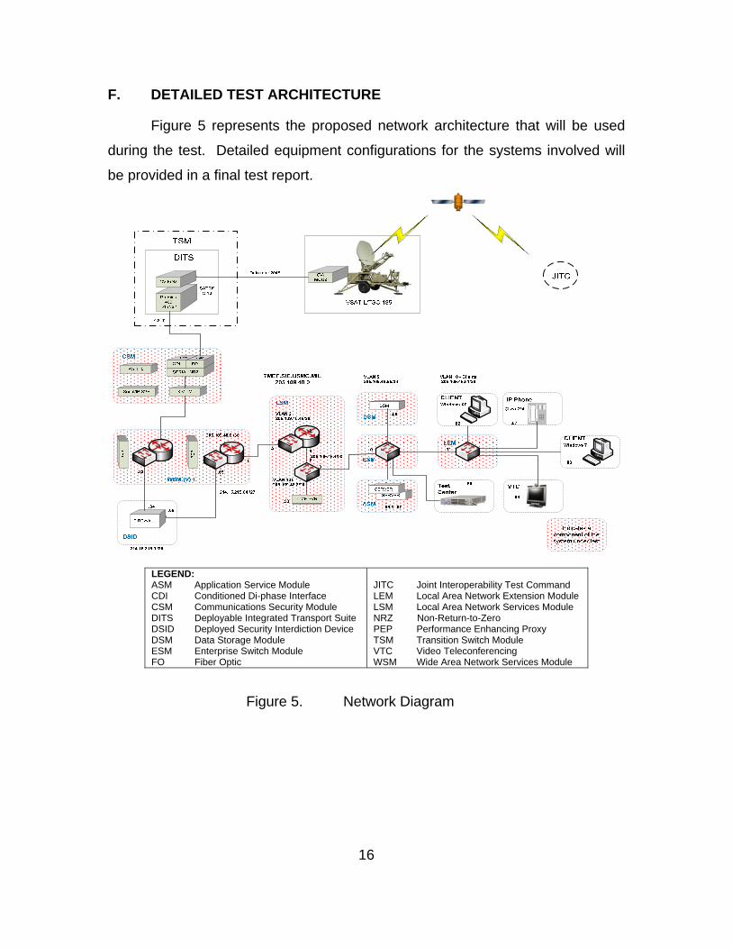
F. DETAILED TEST ARCHITECTURE
Figure 5 represents the proposed network architecture that will be used
during the test. Detailed equipment configurations for the systems involved will
be provided in a final test report.
Figure 5. Network Diagram
LEGEND: ASM Application Service Module CDI Conditioned Di-phase Interface CSM Communications Security Module DITS Deployable Integrated Transport Suite DSID Deployed Security Interdiction Device DSM Data Storage Module ESM Enterprise Switch Module FO Fiber Optic
JITC Joint Interoperability Test Command LEM Local Area Network Extension Module LSM Local Area Network Services Module NRZ Non-Return-to-Zero PEP Performance Enhancing Proxy TSM Transition Switch Module VTC Video Teleconferencing WSM Wide Area Network Services Module
17
III. TEST DESIGN
A. OVERALL TEST APPROACH
The system will be tested using a logical and systematic evaluation
sequence. This approach allows flexibility during testing and attempts to provide
a complete picture of the current IPv6 status of the system. The goal of this test
is to assess and report the present level of functionality (from the user
perspective), the degree of conformance to the standards, comparative
performance measurements, security posture, and interoperability with Joint and
USMC Programs of Record. It is expected that the system will require multiple
iterations of testing in order to meet full compliance. However, since this
approach is designed to be sequential, follow-on tests of individual system
components may not require full regression testing.
The testing approach begins by confirming the individual system
components and network devices provide IPv6 functionality. This functionality is
divided into two categories, limited and basic. For the purposes of this
document, the following definitions are provided:
a. Limited functionality: the component or network device is capable of
assigning an IPv6 address to the Network Interface Card (NIC), can
successfully connect to the network, and can communicate (both
dual-stack and IPv6 native) with other devices on the network.
b. Basic functionality: the application or service is able to function and
communicate (both dual-stack and IPv6 native) with other devices
on the network. During the functionality testing, the associated
ports and protocols used to communicate will be identified and
recorded.
The second area of testing is conformance. Conformance testing will be
conducted on individual system components as stand-alone devices. Since
system components will fall into multiple product classes, they must be evaluated
18
separately, but could be grouped together for testing. The system components
will be tested against the appropriate product class requirements defined in the
DoD IPv6 Standard Profiles for IPv6 Capable Products Version 6.0.
The third area of testing is performance. Performance testing will be
conducted on servers and network devices. The results will provide a basis for
comparison between the network implementations (IPv4, dual-stack, and IPv6).
Examples of the performance metrics to be recorded and analyzed include:
application response time, transactions per second, packet loss, latency, jitter,
and throughput. These metrics will be maintained for future analysis or
comparison during subsequent testing.
The fourth area of testing is security. Host system, server, switch and
router security testing is included in the conformance testing, since the IPv6
security feature requirements are currently defined for each of the product
classes. Information Assurance (IA) devices have unique requirements defined
and will not be included at this time.
The final area of testing is interoperability. Interoperability testing includes
both internal (MAGTF) and external (Joint). Functional testing of the
application(s), service(s), transport, and routing provides the basis for internal
interoperability. Joint interoperability will expand the functional testing by
evaluating interfaces with joint applications, services, transport, and routing.
For this test, one suite will be configured as a legacy (fielded) system and
the second will be configured as an enhanced suite. Examples of the differences
on the enhanced suite include, but are not limited to: servers running Windows
Server 2008 and Exchange 2010 installations and routers/switches upgraded to
newer Cisco Internetwork Operating System (IOS).
B. PLANNED TESTS
The test will be conducted in phases as described in the following
paragraphs. Phase 1 will focus on functionality, performance and
interoperability. During this phase of testing, interoperability of voice, video, and
19
data transmissions between end devices will be evaluated. Functionality and
interoperability testing will include client-to-server, server-to-server, and
SIM/STIM communications as listed in Table 4. Phase 2 will be conformance
testing of individual system components. Phase 3 will be detailed/scheduled at a
later time to assess the security devices within the system. Phase 4 will focus on
joint interoperability. This phase can be combined as part of Phase 1 or
scheduled as a separate phase, to support JITC testing.
Source Destination Service Workstation 1 (local) Workstation 2 (remote) VTC, Ping, Trace-route, Email Workstation 2 (remote) Workstation 1 (local) VTC, Ping, Trace-route, Email Workstation 1 (local) Server 2 (remote) HTTP, HTTPS, SSH, FTP, FTPS Workstation 2 (remote) Server 1 (local) HTTP, HTTPS, SSH, FTP, FTPS Server 1 (local) Server 2 (remote) Mail, VoIP Server 2 (remote) Server 1 (local) Mail, VoIP SIM/STIM 1 (local) SIM/STIM 2 (remote) RFC 2544, Network Loading & Layer 4–
7 SIM/STIM 2 (remote) SIM/STIM 1 (local) RFC 2544, Network Loading & Layer 4–
7
Table 4. Source, Destination, and Service
1. Phase 1: Performance
Phase 1 testing will be divided into three different network scenarios (IPv4,
dual-stack, and IPv6 native). For each scenario, the complete set of test
procedures will be executed on both suites of equipment. Table 5 depicts the
Cisco Internetwork Operating Systems (IOSes) on the 3845 Routers and 3750G
Switches as well as the Operating Systems (OSes) on the servers. Suite 1 is
configured as is currently fielded to Marines using the system in tactical
environments. Known issues exist with the IOS version and OSes; they are not
IPv6 capable. Suite 2 is configured as the engineers at MCTSSA and SYSCOM
have deemed to be the best-case scenario for deployment of the DDS-M.
20
Network Scenario SUITE 1 SUITE 2
Scenario 1: IPv4 Router: 12.4(15)T13, w/ AdvEntServices
Switch: 12.2(50)SE4, w/ IP Services
Servers: Windows Server 2003
Exchange: Microsoft Exchange 2003
Router: 12.4(15)T14, w/ AdvEntServices
Switch: 12.4(50)SE4, w/ IP Services
Servers: Windows Server 2008
Exchange: Microsoft Exchange 2010
Scenario 2: Dual Stack
Scenario 3: IPv6 Native
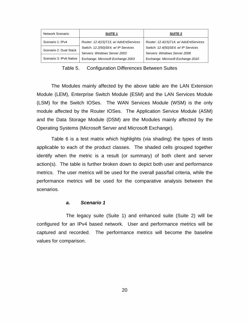
Table 5. Configuration Differences Between Suites
The Modules mainly affected by the above table are the LAN Extension
Module (LEM), Enterprise Switch Module (ESM) and the LAN Services Module
(LSM) for the Switch IOSes. The WAN Services Module (WSM) is the only
module affected by the Router IOSes. The Application Service Module (ASM)
and the Data Storage Module (DSM) are the Modules mainly affected by the
Operating Systems (Microsoft Server and Microsoft Exchange).
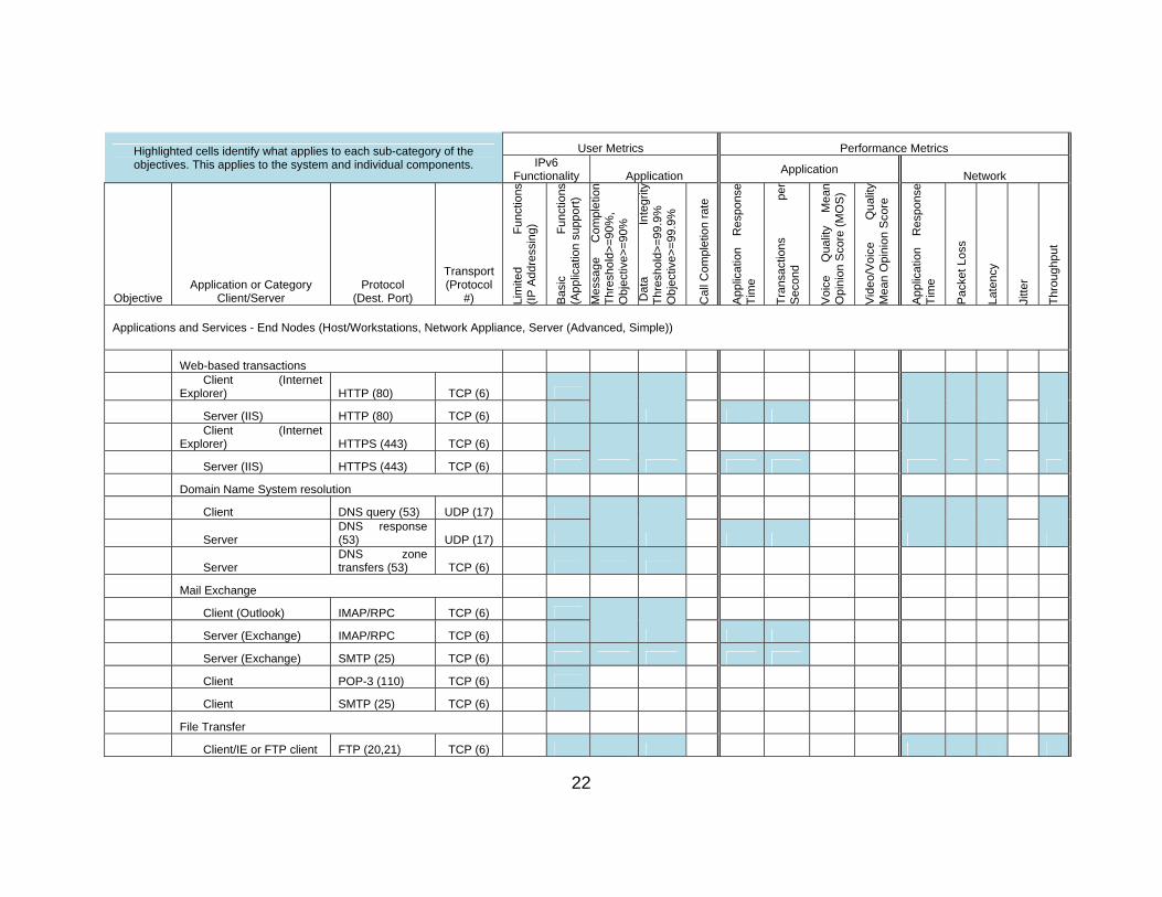
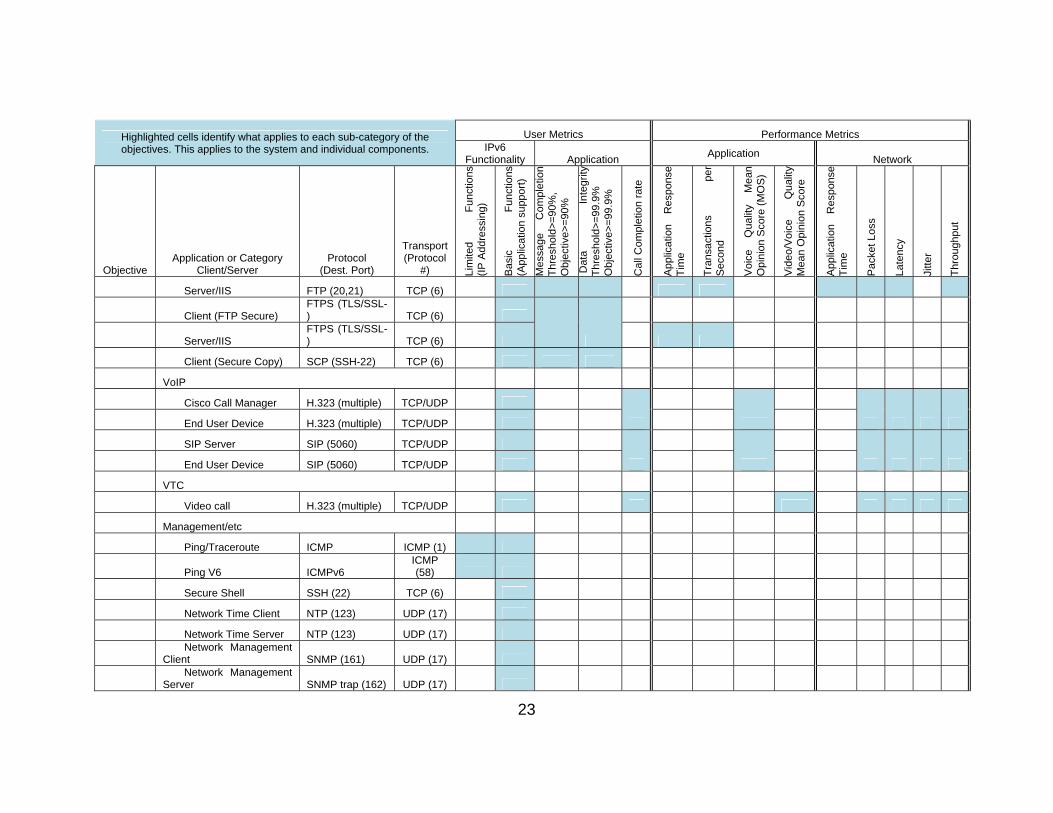
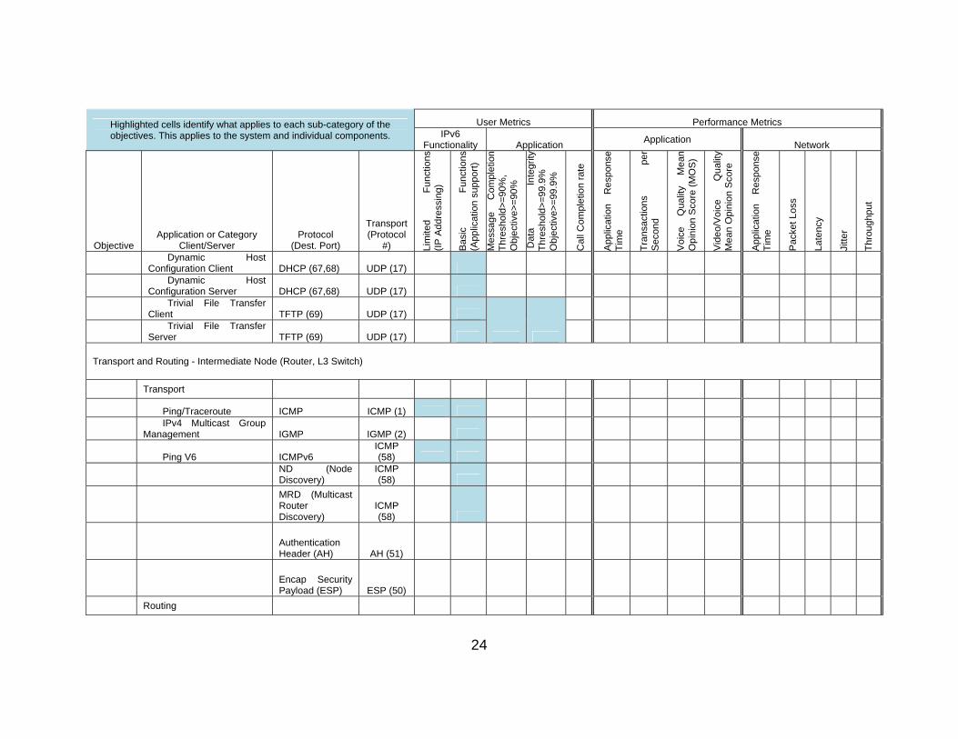
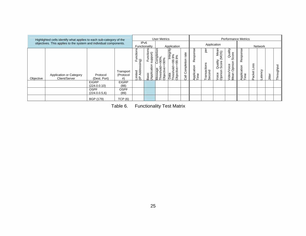
Table 6 is a test matrix which highlights (via shading) the types of tests
applicable to each of the product classes. The shaded cells grouped together
identify when the metric is a result (or summary) of both client and server
action(s). The table is further broken down to depict both user and performance
metrics. The user metrics will be used for the overall pass/fail criteria, while the
performance metrics will be used for the comparative analysis between the
scenarios.
a. Scenario 1
The legacy suite (Suite 1) and enhanced suite (Suite 2) will be
configured for an IPv4 based network. User and performance metrics will be
captured and recorded. The performance metrics will become the baseline
values for comparison.
21
b. Scenario 2
The systems and network devices will be re-configured for dual-
stack operations (IPv4 and IPv6 protocols enabled). The user and performance
metrics will be captured, recorded, analyzed and compared against the baseline
results for Scenario 1.
c. Scenario 3
The systems and network devices will be re-configured for IPv6
native operations (IPv6 enabled and IPv4 disabled). The user and performance
metrics will be captured, recorded, analyzed and compared against the results
for Scenarios 1 and 2.
22
Highlighted cells identify what applies to each sub-category of the objectives. This applies to the system and individual components.
User Metrics Performance Metrics IPv6
Functionality Application Application
Network
Objective Application or Category
Client/Server Protocol
(Dest. Port)
Transport (Protocol
#) Lim
ited
Fu
nctio
ns
(IP
Add
ress
ing)
Bas
ic
Fun
ctio
ns
(App
licat
ion
supp
ort)
Mes
sage
C
ompl
etio
n T
hres
hold
>=
90%
, O
bjec
tive>
=90
%
Dat
a In
tegr
ity
Thr
esho
ld>
=99
.9%
O
bjec
tive>
=99
.9%
Cal
l Com
plet
ion
rate
App
licat
ion
Res
pons
e T
ime
Tra
nsac
tions
pe
r S
econ
d
Voi
ce
Qua
lity
Mea
n O
pini
on S
core
(M
OS
)
Vid
eo/V
oice
Q
ualit
y M
ean
Opi
nion
Sco
re
App
licat
ion
Res
pons
e T
ime
Pac
ket L
oss
Late
ncy
Jitt
e r
Thr
oug
hput
Applications and Services - End Nodes (Host/Workstations, Network Appliance, Server (Advanced, Simple))
Web-based transactions
Client (Internet
Explorer) HTTP (80) TCP (6)
Server (IIS) HTTP (80) TCP (6)
Client (Internet
Explorer) HTTPS (443) TCP (6)
Server (IIS) HTTPS (443) TCP (6)
Domain Name System resolution
Client DNS query (53) UDP (17)
Server DNS response (53) UDP (17)
Server DNS zone transfers (53) TCP (6)
Mail Exchange
Client (Outlook) IMAP/RPC TCP (6)
Server (Exchange) IMAP/RPC TCP (6)
Server (Exchange) SMTP (25) TCP (6)
Client POP-3 (110) TCP (6)
Client SMTP (25) TCP (6)
File Transfer
Client/IE or FTP client FTP (20,21) TCP (6)
23
Highlighted cells identify what applies to each sub-category of the objectives. This applies to the system and individual components.
User Metrics Performance Metrics IPv6
Functionality Application Application
Network
Objective Application or Category
Client/Server Protocol
(Dest. Port)
Transport (Protocol
#) Lim
ited
Fu
nctio
ns
(IP
Add
ress
ing)
Bas
ic
Fun
ctio
ns
(App
licat
ion
supp
ort)
Mes
sage
C
ompl
etio
n T
hres
hold
>=
90%
, O
bjec
tive>
=90
%
Dat
a In
tegr
ity
Thr
esho
ld>
=99
.9%
O
bjec
tive>
=99
.9%
Cal
l Com
plet
ion
rate
App
licat
ion
Res
pons
e T
ime
Tra
nsac
tions
pe
r S
econ
d
Voi
ce
Qua
lity
Mea
n O
pini
on S
core
(M
OS
)
Vid
eo/V
oice
Q
ualit
y M
ean
Opi
nion
Sco
re
App
licat
ion
Res
pons
e T
ime
Pac
ket L
oss
Late
ncy
Jitt
e r
Thr
oug
hput
Server/IIS FTP (20,21) TCP (6)
Client (FTP Secure) FTPS (TLS/SSL- ) TCP (6)
Server/IIS FTPS (TLS/SSL- ) TCP (6)
Client (Secure Copy) SCP (SSH-22) TCP (6)
VoIP
Cisco Call Manager H.323 (multiple) TCP/UDP
End User Device H.323 (multiple) TCP/UDP
SIP Server SIP (5060) TCP/UDP
End User Device SIP (5060) TCP/UDP
VTC
Video call H.323 (multiple) TCP/UDP
Management/etc
Ping/Traceroute ICMP ICMP (1)
Ping V6 ICMPv6 ICMP (58)
Secure Shell SSH (22) TCP (6)
Network Time Client NTP (123) UDP (17)
Network Time Server NTP (123) UDP (17)
Network Management
Client SNMP (161) UDP (17)
Network Management
Server SNMP trap (162) UDP (17)
24
Highlighted cells identify what applies to each sub-category of the objectives. This applies to the system and individual components.
User Metrics Performance Metrics IPv6
Functionality Application Application
Network
Objective Application or Category
Client/Server Protocol
(Dest. Port)
Transport (Protocol
#) Lim
ited
Fu
nctio
ns
(IP
Add
ress
ing)
Bas
ic
Fun
ctio
ns
(App
licat
ion
supp
ort)
Mes
sage
C
ompl
etio
n T
hres
hold
>=
90%
, O
bjec
tive>
=90
%
Dat
a In
tegr
ity
Thr
esho
ld>
=99
.9%
O
bjec
tive>
=99
.9%
Cal
l Com
plet
ion
rate
App
licat
ion
Res
pons
e T
ime
Tra
nsac
tions
pe
r S
econ
d
Voi
ce
Qua
lity
Mea
n O
pini
on S
core
(M
OS
)
Vid
eo/V
oice
Q
ualit
y M
ean
Opi
nion
Sco
re
App
licat
ion
Res
pons
e T
ime
Pac
ket L
oss
Late
ncy
Jitt
e r
Thr
oug
hput
Dynamic Host
Configuration Client DHCP (67,68) UDP (17)
Dynamic Host
Configuration Server DHCP (67,68) UDP (17)
Trivial File Transfer
Client TFTP (69) UDP (17)
Trivial File Transfer
Server TFTP (69) UDP (17)
Transport and Routing - Intermediate Node (Router, L3 Switch)
Transport
Ping/Traceroute ICMP ICMP (1)
IPv4 Multicast Group
Management IGMP IGMP (2)
Ping V6 ICMPv6 ICMP (58)
ND (Node Discovery)
ICMP (58)
MRD (Multicast Router Discovery)
ICMP (58)
Authentication Header (AH) AH (51)
Encap Security Payload (ESP) ESP (50)
Routing
25
Highlighted cells identify what applies to each sub-category of the objectives. This applies to the system and individual components.
User Metrics Performance Metrics IPv6
Functionality Application Application
Network
Objective Application or Category
Client/Server Protocol
(Dest. Port)
Transport (Protocol
#) Lim
ited
Fu
nctio
ns
(IP
Add
ress
ing)
Bas
ic
Fun
ctio
ns
(App
licat
ion
supp
ort)
Mes
sage
C
ompl
etio
n T
hres
hold
>=
90%
, O
bjec
tive>
=90
%
Dat
a In
tegr
ity
Thr
esho
ld>
=99
.9%
O
bjec
tive>
=99
.9%
Cal
l Com
plet
ion
rate
App
licat
ion
Res
pons
e T
ime
Tra
nsac
tions
pe
r S
econ
d
Voi
ce
Qua
lity
Mea
n O
pini
on S
core
(M
OS
)
Vid
eo/V
oice
Q
ualit
y M
ean
Opi
nion
Sco
re
App
licat
ion
Res
pons
e T
ime
Pac
ket L
oss
Late
ncy
Jitt
e r
Thr
oug
hput
EIGRP (224.0.0.10)
EIGRP (88)
OSPF (224.0.0.5,6)
OSPF (89)
BGP (179) TCP (6)
Table 6. Functionality Test Matrix
26
2. Phase 2: Conformance
Phase 2 testing will be stand-alone conformance testing of the individual
system components. The system is comprised of both end nodes and network
devices. These components are categorized in different Product Classes and
have unique conformance test requirements. These test requirements can be
found in the DDS-M Test Procedures at MCTSSA (MCTSSA IPv6 Test
Procedures) and are an excerpt from Section 3 of the DoD IPv6 Standard
Profiles for IPv6 Capable Products Version 6.0. The Spirent Test Center and Ixia
Conformance applications will be used to evaluate the component against the
applicable RFCs and standards.
Each individual module of the DDS-M will be tested by itself against the
Conformance applications of the test tools being used. The configurations of the
Suites will remain the same from Phase 1 (Suite1=Legacy and
Suite2=Enhanced).
3. Phase 3: Security
Phase 3 testing will be security testing of the security or IA devices within
the system. This phase will be scheduled at a later time, as the requirements are
still evolving.
4. Phase 4: Interoperability
Phase 4 testing will be interoperability testing of the system. This will
include both internal (MAGTF) and external (Joint) interoperability.
Interoperability testing can be scheduled as part of Phase 1 or as a separate
phase to support unique JITC testing requirements. JITC normally tests voice,
video and data exchanges between USMC and Joint systems. For the purpose
of this thesis, Interoperability will be tested alongside Phase 1. JITC has test
scripts that emulate OSI Layers 2–4 on Joint Systems and those will be used for
the Interoperability Phase.
27
C. EVALUATION CRITERIA
The evaluation criteria for each test case or requirement is provided in the
Internet Protocol version 6 Test Procedures (MCTSSA IPv6 Test Procedures).
Each requirement will be evaluated with either Pass (P) or Fail (F). “Pass”
indicates the requirement was met. “Fail” indicates the requirement was not met.
The user metrics and interoperability test results will be evaluated against DoD
specifications identified in Tables 7 and 8, provided by JITC.
IE #
Name Producer/
Sender ID
Consumer/ Recipient
ID Critical
Interface Ref (See Table 4–
4)
Criteria
Threshold Objective
1 Unclassified
Data Server
1 Workstation
1 Yes I1
> 90% Transmitted, > 99.9% Data Integrity
> 90% Transmitted, > 99.9% Data Integrity
LEGEND: I Interface ID Identification
IE Information Exchange Ref Reference
Table 7. Information Exchange Requirements
I # Interface Version Critical KIPCriteria
Threshold Objective
I1 Switch/Router Port Yes N/A> 90% Transmitted, > 99.9% Data Integrity
> 90% Transmitted, > 99.9% Data Integrity
LEGEND: I Interface KIP Key Interface Profile
Table 8. Information Exchange Thresholds Requirements
D. PROBLEM REPORTING
All incidents, anomalies, problems, or failures observed during the test will
be reported via a Trouble Incidence Report (TIR) and recorded in a daily test log.
Information from the Daily Test Logs will be combined into a Master Test Log
28
upon completion of the event. The notes from the test logs, TIRs and collected
data will be used for problem analysis. The result of the analysis will be reported
in the final test report. All generated TIRs will be archived in the MCTSSA
Configuration Management library.
E. SUSPENSION CRITERIA AND RESUMPTION REQUIREMENTS
No suspension criteria or resumption requirements have been established.
Individual test cases may require suspension, resumption, or possibly
termination. The decision to suspend or resume testing will be made by the Test
Director and Team Lead.
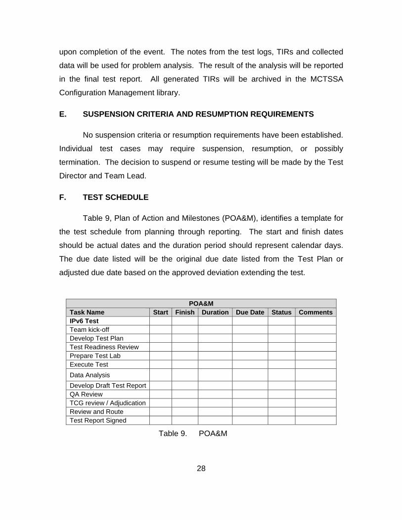
F. TEST SCHEDULE
Table 9, Plan of Action and Milestones (POA&M), identifies a template for
the test schedule from planning through reporting. The start and finish dates
should be actual dates and the duration period should represent calendar days.
The due date listed will be the original due date listed from the Test Plan or
adjusted due date based on the approved deviation extending the test.
POA&M Task Name Start Finish Duration Due Date Status CommentsIPv6 Test Team kick-off Develop Test Plan Test Readiness Review Prepare Test Lab Execute Test
Data Analysis
Develop Draft Test Report QA Review TCG review / Adjudication Review and Route Test Report Signed
Table 9. POA&M
29
IV. CONCLUSION AND RECOMMENDATIONS
A. FUTURE WORK AT MCTSSA
1. The Foundation has been Laid
Once the DDS-M completes testing, all other tactical programs of record
will be tested behind (while attached to) the DDS-M. Preliminary tests indicate
that the DDS-M will have no issues with passing the Dual Stacked portions of the
requirements in the USMC IPv6 Transition Plan, so a lab has been built that will
emulate the DDS-M at MCTSSA.
The test plan laid out goes into great detail for functionality and
performance testing Layers 2–4 of the OSI Model on the DDS-M. Further
research needs to be conducted into the area of IPv6 Security; the focus of this
thesis is on performance, conformance, and interoperability, but Security should
not be neglected in follow on work(s).
2. The Need for an IPv6 Lead
A need exists at MCTSSA to lead this efforts. Headquarters Marine Corps
is pushing this effort, but the Programs of Record rely on MCTSSA to perform the
appropriate testing for this transition. The ideal individual to occupy this billet will
meet the below requirements:
Marine Corps Captain
Information Technology Management and/or a Computer Science
Masters Degree
Communications Officer (0602) Military Occupation Specialty
Deployed and/or Combat Experience

30
THIS PAGE INTENTIONALLY LEFT BLANK

31
BIBLIOGRAPHY
Desmeules, R. Cisco Self-Study: Implementing Cisco IPv6 Networks. Indiana: Cisco Press, 2007.
DISR IPv6 Standards Technical Working Group. “DoD IPv6 Standard Profiles for IPv6 Capable Products Version 6.0.” Washington, DC: Department of Defense, 2011.
DoD Chief Information Officer Memorandum. “Internet Protocol Version 6 (IPv6) Interim Transition Guidance.” Washington, DC: Department of Defense, 2003.
DoD IPv6 Transition Office. “DoD Chief Information Officer (CIO) Memorandum, IPv6.” Washington, DC: Department of Defense, 2003.
Government Accounting Office (GAO). “Internet Protocol Version 6: Federal Agencies Need to Plan for Transition and Manage Security Risks.” Last modified May, 2005. http://www.gao.gov/new.items/d05471.pdf.
Grossetete, P., C. Popoviciu, and F. Wettling. Global IPv6 Strategies: From Business Analysis to Operational Planning. Indiana: Cisco Press, 2008.
Hagen, S. IPv6 Essentials, 2nd ed. California: O’Reilly, 2006.
Headquarters Marine Corps Command, Control, Communications, and Computers Plans and Policy Division. “United States Marine Corps Internet Protocol Version 6 (IPv6) Transition Plan. Unclassified - For Official Use Only.” Washington, DC: Department of Defense, 2008.
Joint Requirements Oversight Council. “Global Information Grid (GIG) Mission Area Initial Capabilities Document (MA ICD), JROCM 202–02.” Washington, DC: Department of Defense, 2004.
MCTSSA. “Internet Protocol version 6 Test Procedures.” Washington, DC: Department of Defense, 2011.
Office of Management and Budget. “Memorandum 05–22. SUBJECT: Transition Planning for Internet Protocol version 6 (IPv6).” Last modified August 2, 2005. http://www.whitehouse.gov/omb/memoranda/fy2005/m05–22.pdf.
Popoviciu, C., E. Levy-Abegnoli, and P. Grossetete. Deploying IPv6 Networks. Indiana: Cisco Press, 2006.

32
QinetiQ-NA. “Recommended Approach for USMC Tactical IPv6 Implementation: Prepared for MCSC Product Group 12 by QinetiQ-NA.” Restricted Document. Washington, DC: Department of Defense, 2008.
33
INITIAL DISTRIBUTION LIST
1. Defense Technical Information Center Ft. Belvoir, Virginia
2. Dudley Knox Library Naval Postgraduate School Monterey, California