TRANSFER SYSTEM LTE - Montech · TRANSFER SYSTEM LTE The single-belt transfer system from Montech...
52
TRANSFER SYSTEM LTE more than technology
-
Upload
vuongtuong -
Category
Documents
-
view
217 -
download
2
Transcript of TRANSFER SYSTEM LTE - Montech · TRANSFER SYSTEM LTE The single-belt transfer system from Montech...

TRANSFER SYSTEM LTE
more than technology

CUSTOMIZED SOLUTIONS
Assembly Watch industry Electronics industry Construction industry
Mechanical engineering Printing industryPlastics industry
Automotive
Automotive suppliers
Automotive suppliers Solar industry
Automotive suppliers
Medical industry
Airport industry
Medical industry
Automotive
Mechanical engineering
Electronics industry
Airport industry

3LTE 02/2013
TRANSFER SYSTEM LTE
The single-belt transfer system from Montech is an asynchro-
nous transfer system whose function is to automatically
guide workpieces through the necessary workstations accord-
ing to their asssembly sequence.
The workpieces to be processed are attached to standardized
workpiece holders made of high-strength plastic and are
carried on single-belt conveyors.
The modular system makes it possible to implement the
automation process step-by-step. Subsequent modifications
can be made with minimum expenditure.
PRODUCT DESCRIPTION 3
TECHNICAL DATA 5
WORKPIECE HOLDER WTE 8
CONVEYOR TB/TBD 11
BYPASS CONVEYOR BPBE 16
BELT COUPLING BKE 18
BELT FABRICATION 20
CONVEYORS COMPONENTS 22
CURVES KFE/KBEA 27
ROTARY DIVERTERS UR-180° 31
BYPASS BPEA/BPE 37
TRANSFER GATE WEE 40
INDEXING DEVICE IVE/IVEB 42
POSITIONING UNIT PVE 46
ACCESSORIES 49
Modifications may be made without notice.

4 02/2013 LTE
Typical application criteria are:
• assembly automation and logistics
• system arrangement «inline» and/or «offline»
• repeatability ± 0.05 mm
• four workpiece holders: 80 x 80, 115 x 115, 160 x 160 and
225 x 225 mm
To ensure a high degree of flexibility, we recommend the use of
the profile system Quick-Set as a substructure. It is based on a
dovetail clamping principle, requires no drilling or pinning, and
can be used universally.
TRANSFER SYSTEM LTE - PRODUCT DESCRIPTION

5LTE 02/2013
TRANSFER SYSTEM LTE - TECHNICAL DATA
Ambient temperature +10 to +40 °C
Rel. humidity < 95% (without condensation)
Air purity normal workshop atmosphere
Noise level [dBA] < 70
Gear motor
voltage/frequency 3×230 V/ 50/60 Hz (r)
3×400 V/ 50/60 Hz (å)
frequency converter 1×230 V/ 50 Hz
category of protection IP55
type of switching delta/star (factory state)
nominal rating [W] 180
winding with 3 temperature contacts
rated current [A] delta: 1.2
[A] star: 0.7
Repeatability
WTE in IVE/IVEB/PVE [mm] ± 0.05
Workpiece holder WTE sizes 80× 80 mm (weight: 170 g)
115×115 mm (weight: 360 g)
160×160 mm (weight: 690 g)
225×225 mm (weight: 1660 g)
Max. weight WTE 80, 115, 160 (with load) [kg] 2.5
Max. weight WTE 225 (with load) [kg] 5
Max. torque on WTE in IVE/IVEB [Nm] 5
Max. pressure on WTE in IVE/IVEB [N] 120
Max. pressure on WTE in PVE* [N/mm2] 15
Operating pressure [bar] 5–6
Operating medium air, oiled or unoiled, filtered to 5 µm, dew point < 6 °C
Material workpiece holder WTE polyethyleneterephtalat PET, black
Material lateral guide polyethylene PE, black, antistatic
Belt type (recommended) ENI-5EE, antistatic; manufacturer Habasit
* this force is dependent on the material of the workpiece support (polyethyleneterephtalat) and is therefore statedin N/mm2.

6 02/2013 LTE
MAXIMUM TORQUE POSITIONING UNIT PVE
WTE 80´80
Center 4.0 Nm
0 to 30 mm 3.5 Nm
30 to 60 mm 3.0 Nm
WTE 115´115
Center 6.0 Nm
0 to 40 mm 4.5 Nm
40 to 80 mm 3.0 Nm
WTE 160´160
Center 6.5 Nm
0 to 60 mm 5.5 Nm
60 to 120 mm 5.0 Nm
60
80
80
30
40
80
115
115
60
120
160
160
225
225
180
90
WTE 225´225
Center 7.0 Nm
0 to 90 mm 6.0 Nm
90 to 180 mm 5.5 Nm

7LTE 02/2013
Changeover times (with belt type ENI-5EE)
Times indicated refer to the time for setting and setting back the curve with drive, or the transfer gate, or thebypass with drive, plus the transit time of the workpiece holder.For the curve and the bypass BPE without drive, the time indicated refer the time for setting and setting back plusthe transit time of the workpiece holder.
Speed 7.7 m/min 9.7 m/min 12.3 m/min 14.9 m/min 18.7 m/min
Indexing device IVE/ IVEB
IVE/ IVEB-105 0.70 0.55 0.45 0.40 0.35
IVE/IVEB-140 0.95 0.80 0.65 0.55 0.50
IVE/IVEB-185 1.30 1.05 0.85 0.70 0.60
IVE/IVEB-250 1.75 1.40 1.15 0.95 0.75
Positioning unit PVE
PVE-105 0.70 0.55 0.45 0.40 0.35
PVE-140 0.95 0.80 0.65 0.55 0.50
PVE-185 1.30 1.05 0.85 0.70 0.60
PVE-250 1.75 1.40 1.15 0.95 0.75
Movable curve with drive KBEA
KBEA-105 3.7 3.2 2.6 2.2 1.9
KBEA-140 4.7 3.9 3.3 2.8 2.5
KBEA-185 5.7 4.7 3.9 3.5 2.9
KBEA-250 6.8 5.6 4.5 3.8 3.1
Movable curve without drive KBE
KBE-105 2.9 2.3 1.9 1.6 1.4
KBE-140 3.6 2.9 2.5 2.2 1.8
KBE-185 4.7 3.9 3.0 2.6 2.2
KBE-250 6.2 5.0 4.0 3.4 2.7
Transfer gate WEE
WEE-105 3.4 2.7 2.3 2.1 1.7
WEE-140 4.1 3.4 2.8 2.5 2.2
WEE-185 5.8 4.7 3.9 3.5 2.8
Bypass with drive BPEA
BPEA-105 5.3 4.4 3.6 3.0 2.5
BPEA-140 6.3 5.1 4.0 3.5 2.8
BPEA-185 6.8 5.8 4.5 3.9 3.2
BPEA-250 8.8 7.2 5.9 5.0 4.2
Bypass without drive BPE
BPE-105 – – 2.8 2.4 1.9
BPE-140 – – 4.1 3.6 3.0
BPE-185 – – 4.3 3.6 2.9
BPE-250 – – 5.8 4.8 4.0
TRANSFER SYSTEM LTE - TECHNICAL DATA

8 02/2013 LTE
The workpiece holder WTE made from high-strength plastic is available in
four standard sizes: 80×80, 115×115, 160×160 and 225×225 mm.
Depending on the design of the pallet transfer system and the preferred
direction of transport, version A or mirrored version B is used. The permis-
sible total weight of each workpiece holder, including workpiece receiver
and product, is 2.5 kg.
PRODUCT DESCRIPTION WORKPIECE HOLDER WTE

9LTE 02/2013
7
A
B
C
10
D
4
F
E
1G Ø 8
10
20
H
3
WORKPIECE HOLDER WTE - DIMENSIONS
Type WTE 80´80 WTE 115´115 WTE 160´160 WTE 225´225
for TB-105 for TB-140 for TB-185 for TB-250
A 80 115 160 225
B 40 57.5 80 112.5
C 17 25 45 25
D 80 115 160 225
E 19 19 19 19
F 24 24 24 24
G 30 57 72 77
H 55 90 135 200
Ref. No.
Version A 49609 49610 49611 56307
Version B 49639 49638 49636 56306
CAD Data

10 02/2013 LTE
WORKPIECE HOLDER WTE - DIMENSIONS
Version B
115×115 mmVersion A
160×160 mmVersion A
225×225 mmVersion A
80×80 mmVersion A
115×115 mmVersion B
160×160 mmVersion B
225×225 mmVersion B
80×80 mmVersion B
Version A

11LTE 02/2013
CONVEYOR TB - PRODUCT DESCRIPTION
The conveyor both modular and proven in design forms the
basis of the transfer system. Chassis widths of 105, 140, 185
and 250 mm are used for the respective workpiece holders.
The conveyors are driven by a 3×230/400 V central spur gear
drive. Belt speeds can be varied simply and economically
between 7.5 and 19.9 m/min using conversion kits.
The construction is precise, stable and durable. All steel parts
are nickel plated or made from non-corroding materials;
deflecting rollers are stainless, and the drive rollers are
coated with vulcanized rubber.

12 02/2013 LTE
CONVEYOR SINGLE-BELT WITH DRIVE HORIZONTAL TB - DIMENSIONS
Type TB-105 TB-140 TB-185 TB-250
A chassis [mm] 105 140 185 250
B conveyor width ±0.5 mm [mm] 33–83 68–118 113–163 178–228
C gliding plate [mm] 84 119 164 229
X belt width [mm] 75 90 135 200
L total length horizontal drive min. 385 mm – max. 3 m
(at certain conditions may even longer bands are allowed))
min. 90
33139
205
111.
5L
256
40
14
1
min. 90
Ø 30
Ø30
60 60
max. 282
max
.16
7
max
.20
7
46
A
13
Ø 124US362/B141
336 9
9
2.55.5
11
9
416
12
40
14
7.5
1
X
B
C
0.25 0.25
A
11.75
A
A
A–A
left rightDirection of travel
Configurator CAD Data

13LTE 02/2013
CONVEYOR SINGLE-BELT WITH DRIVE VERTICAL TB - DIMENSIONS
Type TB-105 TB-140 TB-185 TB-250
A chassis [mm] 105 140 185 250
B conveyor width ±0.5 mm [mm] 33–83 68–118 113–163 178–228
C gliding plate [mm] 84 119 164 229
X belt width [mm] 75 90 135 200
L total length vertical drive min. 324 mm – max. 3 m
(at certain conditions may even longer bands are allowed))
L2
41
3378
144
Ø 30Ø
30
min. 90min. 90
155.5
60 60
40
27
0
max
.34
7
max
.30
7
A46
Ø 124US362/B141
336 13 9
9
2.55.5
11
9
416
12
40
14
7.5
1
X
B
C
A
0.250.25 11.75
A
A
A–A
Direction of travelleft right
Configurator CAD Data

14 02/2013 LTE
min. 90
33139
205
111.
5L
256
40
max
.16
7
Ø30
max
.20
7
141
min. 90
Ø 30
max. 282
60 60
99
Ø 124US362/B141
46
A
336 13
2.55.5
11
9
416
12
40
14
7.5
1
B
C
A
0.25
25 16 16D 25
0.25
A–A
11.75
A
A
left rightDirection of travel
CONVEYOR DUAL-BELT WITH DRIVE HORIZONTAL TBD - DIMENSIONS
Type TB-105 TB-140 TB-185 TB-250
A chassis [mm] 105 140 185 250
B conveyor width ±0.5 mm [mm] 55–83 90–118 135–163 200–228
C gliding plate [mm] 84 119 164 229B
D belt distance [mm] 23 58 103 168
L total length horizontal drive min. 385 mm – max. 3 m
(at certain conditions may even longer bands are allowed))
Configurator CAD Data

15LTE 02/2013
Type TB-105 TB-140 TB-185 TB-250
A chassis [mm] 105 140 185 250
B conveyor width ±0.5 mm [mm] 55–83 90–118 135–163 200–228
C gliding plate [mm] 84 119 164 229B
D belt distance [mm] 23 58 103 168
L total length verticalal drive min. 324 mm – max. 3 m
(at certain conditions may even longer bands are allowed))
L
40
Ø30
Ø 303378
144
min. 90 min. 90
241
270
max
.307
max
.347
155.5
60 60
9
Ø 124US362/B141
9
A46
366 13
2.55.5
11
9
416
12
40
14
7.5
1
B
C
A
0.25
25 16 16D 25
0.25
A–A
11.75
A
A
left rightDirection of travel
CONVEYOR DUAL-BELT WITH DRIVE VERTICAL TBD - DIMENSIONS
Configurator CAD Data

16 02/2013 LTE
PRODUCT DESCRIPTION BYPASS CONVEYORS BPBE
The bypass belt permits the installation of two parallel con-
veying sections with only one drive unit. The distance
between the two conveyor belts is 12 mm. Consequently,
the inward and outward transfer elements (see catalog, pages
37 to 39) can be installed in the bypass belt for construction
of a bypass.

17LTE 02/2013
BYPASS CONVEYORS BPBE SINGLE-BELT WITH GLIDING PLATE - DIMENSIONS
AA
124
6
9
C
X
A
B
10.5
0.25
(4)1
6 96
11
2.5 5.5
1
0.25
C
X
B
1
1412
40
A
10.5
12
12 12
min. 90
33139
205
111.
5L
256
40
14
1
min. 90
Ø 30
Ø30
60 60
max. 282
max
.16
7
max
.20
7
Ø 124US362/B141
9
13
A – A
A
A
Type BPBE-105 BPBE-140 BPBE-185 BPBE-250
A chassis [mm] 105 140 185 250
B conveyor width ±0.5 mm [mm] 81 116 161 226
C gliding plate [mm] 84 119 164 229
X belt width [mm] 75 90 135 200
L total length horizontal drive min. 385 mm /
max. 10 m – belts over 10 m long on request
CAD Data

18 02/2013 LTE
PRODUCT DESCRIPTION BELT COUPLING BKE
0.25 0.25
A
B
D25 16 16 25
40
14
112.5 5.5(4
)16 9
12
6 1
10.5 CB
A
115.52.5
6916
(4)
0.25
1240
14
0.25X
C10.5
1
The belt coupling BKE is used for coupling a double-
belt conveyor TBD to a single-belt conveyor TBE, for
example for use as a positioning unit PVE (see
page 46). Force transmission from conveyor to con-
veyor is by means of a synchronous belt drive. Conse-
quently, no second conveyor drive is required.
At the same time, the belt coupling BKE is also used
for special applications, e.g. in conveyors in hot zones
if it is not possible to use a drive at the given tempera-
tures.
Type A [mm] B ± 0.5 mm C [mm] X [mm]
TBE-105 105 81 84 75
TBE-140 140 116 119 90
TBE-185 185 161 164 135
TBE-250 250 226 229 200
Type A [mm] B ± 0.5 mm C [mm] D [mm]
TBE-105 105 81 84 23
TBE-140 140 116 119 58
TBE-185 185 161 164 103
TBE-250 250 226 229 168

19LTE 02/2013
L = min. 225 / max. 2000
60 100
37
100
7
L
Ø 30
14111
1.5
min. 90
40
37
7
Ø 40 Ø 40
min. 105
90
90
Ø 30
105 105
105105
46
A
13
Ø 124US362/B141
33
6
99
60
46
A
13
Ø 124US362/B141
33
6
99
256
256
BELT COUPLING BKE WITH GLIDING PLATE - DIMENSIONS
Belt coupling TBD/TBE(double belt ª single belt)
Belt coupling TBE/TBE(single belt ª single belt)
CAD Data

20 02/2013 LTE
Structure of our code: 15/0135/09085/1
TB-center drive Belt definition: TB-185, L= 4450 mm, with 1×deflecting roller Ø 30 mm,
belt type ENI-5EE
according to formula on page 21: G = (2 × L + 237 mm) = 9137 mm
Belt definition 15/0135/09137/1
LIST OF BELT CODES
CALCULATION EXAMPLES
Connection code (see code below)
Belt length (always 5-digit)
Belt width (always 4-digit)
Belt number (see code below)
No. Belt designation Connection code Supplier
15 ENI-5EE 1 / 3 / 4 Habasit
Connection code 1 = endless flexproof
Connection code 2 = endless thermofix
Connection code 3 = open beveled
Connection code 4 = cut square
Prefere connection code 1 or 2!
Version 1 You order the belt yourself from the manufacturer in the table below.You determine the belt length using the formula at the bottom of page 20.
Version 2 Montech procures the belt for you according to the list of belt codes below
CONVEYORS LTE BELT FABRICATION
Manufacturer’s design. ENI-5EE
Thickness [mm] 1.2
Dimensions [kg/m2] 1.2
Min. drum Ø [mm] R41)
k1% [N/mm] 5
kzul. [N/mm] 8
Operating temp.
cont. [°C] –30/80
Operating temp.
briefly [°C] –30/100
Field of use Mo, El
Method of transport
horizontal X
buffering X
rejection of goods X
inclined
Surface struc-
of conveying side tured
Cleats no
Color of conveying side black
Antistatic yes
Suitable for food no
1) Nose bar radius
k1% Required force for 1% elongation
kperm. Maximum permissible force
Mo Mounting systems, general
El Electronics industry (electrically conductive)

21LTE 02/2013
L
Lc
LG
CONVEYORS LTE CALCULATION FORMULAS FOR CHASSIS, GLIDING PLATE AND BELT LENGTHS
LLc
LG
Drives horizontal Drives vertical
Calculation of chassis length Drives horizontal/vertical
Chassis length Lc = L – 120 mm
Calculation of gliding plate
Gliding plate length LG = L – 121 mm
Calculation of belt length
TB with 2 deflection rollers Ø 30 mm G = (2 × L) + 237 mm
TB with additional tensioning station Gs = G + 280 mm
Belt coupling Drives horizontal vertical
Calculation of chassis length
Chassis length LC = LTB-BKE – 110 mm LC = LBKE – 140 mm
Calculation of gliding plate
Gliding plate length LG = LTB-BKE – 111 mm LG = LBKE – 141 mm
Calculation of belt length
TB with 2 deflection rollers GTB-BKE = (2 × LTB-BKE) + 242 mm GBKE = [(2 × LBKE) + 32 mm] × 0.994
(1 x Ø 30 mm / 1 x Ø 40 mm)
LL
Lc
L
Lc
L
TB-BKE BKE
GG
Ø30
Ø30
Ø40
Ø40
Configurator

22 02/2013 LTE
CONVEYORS TB - COMPONENTS
LTE spur gear motors Ref. No.
US362/B141 (v=7.7–18.7 mm/min) 521112
Intermediate ring (flange) 44774
Sprocket set for motor type US362/B141 Ref. No.
v [m/min]
z=12/Ø12 7.7 58657
z=15/Ø12 9.7 44980
z=19/Ø12 12.3 44981
z=23/Ø12 14.9 44982
z=29/Ø12 18.7 58658
Motor support for vertical drive Ref. No.
TB-105 to TB-250 62530

23LTE 02/2013
TB chassis for gliding plate Ref. No.
TB-105 L=....* 58787/....*
TB-140 L=....* 58788/....*
TB-185 L=....* 58789/....*
TB-250 L=....* 58790/....*
* customer-specific in mm, max. 3000 mm
CONVEYORS SINGLE-BELT TB - COMPONENTS
TB conveyor Ø30 end with deflection
roller, single-belt Ref. No.
TB-105 56990
TB-140 56991
TB-185 56992
TB-250 56993
TB drive unit horizontal, single-belt Ref. No.
TB-105 58687
TB-140 59272
TB-185 59273
TB-250 59274
TB drive unit vertical, single-belt Ref. No.
TB-105 58688
TB-140 59280
TB-185 59281
TB-250 59282

24 02/2013 LTE
CONVEYORS DUAL-BELT TBD - COMPONENTS
Gliding plate stainless Ref. No.
TB-105 L=.... (till max. 1500 mm)* 58791/0084/....*
TB-140 L=.... (till max. 1500 mm)* 58791/0119/....*
TB-185 L=.... (till max. 1500 mm)* 58791/0164/....*
TB-250 L=.... (till max. 2000 mm)* 58791/0229/....*
* customer-specific in mm, multiple plates possible
When ordering chassis for gliding plate and glide platewithout assembly, the gliding plate is attached only percustomer’s request.
TBD Conveyor Ø30 end with deflection rollers, dual-belt
TBD-105 56994
TBD-140 56995
TBD-185 56996
TBD-250 56997
TBD drive unit horizontal, dual-belt Ref. No.
TBD-105 58697
TBD-140 59275
TBD-185 59276
TBD-250 59277
TBD drive unit vertical, dual-belt Ref. No.
TBD-105 58719
TBD-140 59283
TBD-185 59284
TBD-250 59285

25LTE 02/2013
BYPASS CONVEYORS BPBE - COMPONENTS
BPBE conveyor end with deflection roller Ref. No.
TB-105 56990
TB-140 56991
TB-185 56992
TB-250 56993
Chassis binder BPBE Ref. No.
BPBE 55145
BPBE drive unit horizontal Ref. No.
TB-105 62298
TB-140 62302
TB-185 62440
TB-250 62445

26 02/2013 LTE
BELT COUPLING BKE - COMPONENTS
BKE conveyor end with deflection
rollers, dual-belt Ref. No.
TBD-105 55211
TBD-140 55212
TBD-185 55213
TBD-250 56297
BKE belt coupling single-belt Ref. No.
TB-105 55396
TB-140 55397
TB-185 55398
TB-250 56299
BKE conveyor end with deflection
roller, single-belt Ref. No.
TB-105 55208
TB-140 55209
TB-185 55210
TB-250 56298
BKE belt coupling dual-belt Ref. No.
TBD-105 55399
TBD-140 55400
TBD-185 55401
TBD-250 56296

27LTE 02/2013
PRODUCT DESCRIPTION FIXED CURVE 90º KFE
The kit for fixed curve 90° KFE can simply screwed onto the
conveyor profile.
A finger protection device between the conveyors is also
installed manually; it ensures optimum operational safety. In
only a few minutes, the 90° connection can be installed.
The fixed curve allows queing while within the curve. This
keeps the control system simple and saves costs as there is
no need for stoppers in front of the curves.
As an alternative to two fixed curves, with 180° deflections,
the rotary diverter UR-180 can be used.

28 02/2013 LTE
FIXED CURVE 90° KFE - DIMENSIONS VERSION E
FIXED CURVE 90° KFE - DIMENSIONS VERSION M
D
C
B
9.814
A
28.5
28.5
14 C
B
A
Type KFE-105 zu TB-105 KFE-140 zu TB-140 KFE-185 zu TB 185 KFE-250 zu TB-250
A chassis [mm] 105 140 185 250
B [mm] 178 253 335 468
C [mm] 150 190 230 250
D [mm] 215 250 295 360
Ref. No.
Version E 49617 49618 49619 56312
Version M 49634 49633 49632 56313
CAD Data

29LTE 02/2013
PRODUCT DESCRIPTION MOVABLE CURVE 90º KBEA/KBE
The movable curve 90° KBE can be used for inward and
outward transfer in a bypass. Just like the fixed curve, the
movable curve can be integrated into an existing transfer
system in a later phase.
At the inward end, stoppers are necessary (not included in
the scope of delivery, see options).
All further technical data of the movable curve 90°, like load-
ing of the WTs, correspond to the data on page 7.
Safety instructions
The operating pressure for the cylinder on the movable curve
may be not more than two bar. Otherwise, there is a danger
of injury.
KBE with drive
KBE without drive

30 02/2013 LTE
H
D
CAB
609
1A
E
F
G
16 D
C A
E
F
16
B
60 91
105
H
G
40 14
11
3.3
11.5
13.4
40
3.3
25.4
46 14
11
11.5
H
G
16
B
60
23
9.7
A
D
C
A
E
F
H
G
609
1
A
120
A
16
B
D
C
E
F
Type KBEA/KBE-105 KBEA/KBE-140 KBEA/KBE-185 KBEA/KBE-250
for TB-105 for TB-140 for TB 185 for TB-250
A [mm] 105 140 185 250
B [mm] 43.8 51.7 57.1 56.3
C [mm] 79 117.5 133 144.8
D [mm] 58 100.9 116.4 221
E [mm] 22 51.3 76.9 93.8
F [mm] 58 117.5 133 221
G [mm] 83.5 93.5 108.5 160.5
H [mm] 152.3 200.2 245.6 316.7
Installation left Installation right
Installation left Installation right
MOVABLE CURVE 90° WITH DRIVE KBEA
Ref. No.
KBEA 54506 54629 54613 56011
KBE 54610 54612 54614 56375
MOVABLE CURVE 90° WITHOUT DRIVE KBE

31LTE 02/2013
PRODUCT DESCRIPTION ROTARY DIVERTER UR-180°
The rotary diverter UR-180° is employed in transport systems
for diverting the workpiece holder from the forwards strand
to the reverse strand or from the reverse strand to the
forward strand.
The distance between the forward and reverse strands is
determined as 210 mm by the diverter type UR-1/180° to UR-
4/180° and cannot be changed.
The UR-180° consists of a flexible turntable, driven by an
electric motor, which is diverted by 90° downwards by
deflecting rollers. This design results in optimal space condi-
tions for the mechanical connection to the incoming and
outgoing conveyor belts. The gearing is protected against
overloading by a slip clutch mechanism.
To avoid queues on the diverter, the workpiece holders are
separated (by a definite distance) prior to diversion. The
minimum diversion time is 1.4 s per workpiece holder, this
corresponds to the shortest possible cycle time of an installa-
tion of this kind.

32 02/2013 LTE
Belt speed of 50 Hz
size 1 (TB/TBD 105),
diversion radius 157.7 mm [m/min] 14.6
size 2 (TB/TBD 140),
diversion radius 175.0 mm [m/min] 16.2
size 3 (TB/TBD 185),
diversion radius 197.5 mm [m/min] 18.3
Speed tolerance ± 10%
Perm. mass of WT when conveying [kg] 5.0
Voltage / frequency 3 x 400/230 V, 50/60 Hz
Rated currents 3 x 400 V, 50 Hz, 0.4 A
3 x 230 V 50 Hz, 0.7 A
Degree of protection of motor IP 54
Noise level [dBA] < 50
Weight size 1 [kg] 16.6
size 2 [kg] 18.3
size 3 [kg] 20.8
Material lateral guide polythene PE, black, antistatic
deflecting roller steel
turntable steel
replacement belt TT-04 (Manufacturer Ammeraal Beltech AG)
Criteria for use
Ambient temperature +10 to +40 °C
Rel. humidity < 95% (without condensation)
Relative humidity variation ± 10%
Air purity normal workshop atmosphere
ROTARY DIVERTERS UR-180° - TECHNICAL DATA
Important restrictions:– No moisture or fluids of any kind– No loose parts, waste or debris– No direct UV radiation– No temperature above the ambient value
A rotary diverter 180 ° for TB-250, WTE 225×225 can be realized with 2× fixed curve KFE .See example page 34

33LTE 02/2013
ROTARY DIVERTERS UR-180° - DIMENSIONS
A A
E
G
F
Ø1
22
.2 95
.1
7279
291
320
54
76 C
B
13 D
Type UR-1 for TB-105 UR-2 for TB-140 UR-3 for TB 185
WTE 80´80 WTE 115´115 WTE 160´160
A [mm] 105 140 185
B [mm] 286 321 366
C [mm] 97 101 101
D [mm] 146.2 182.2 200.2
E [mm] 420 490 580
F [mm] 224.5 218.5 209.5
G [mm] 195 230 275
for Quick-Set attachment
Ref. No.
56214 56280 56281
CAD Data

34 02/2013 LTE
SAMPLES FOR A ROTARY DIVERTER 180° WITH TB-250
A rotary diverter UR-180 for the TB-250 (WT 225 x 225) can be realized in
accordance with this dimension. Detailed data on Fixed curve (KFE)
see page 27 ff.
If the distance between the belts is smaller than 441 mm, the curved shape
must be adapted accordingly (custom curves) and the drive is arranged
vertically. For questions, we will help you.
210
TB
-25
0
710
729
TB-250
460
min
. 9
41
min
. 9
60
min
. 4
41
TB
-25
0
TB-250
min
. 6
91
KFE-250(56312)

35LTE 02/2013
SEQUENCE OF MOVEMENTS OF UR-180°
Start
Z1 back
Z1 forwards
noyes
WT forwards WT-Anschlag, N1 occupied,
Queue monitor S1 free
WT stop back,
Start delay for T
Delay for T expired
Delay for T expired
Sequence of movements of,
Start delay for T
noyes
noyes
No queueing on the rotary diverter.
Z1
S1 N1Single-belt
Basic position: Z1 forwards
Z1 = WT stop (pneumatic cylinder)
N1 = Proximity switch
S1 = Queue monitor

36 02/2013 LTE
MN
K
H
80
±2
0
184
LP-66-40/TP-66-40
LP-66-40
EV-3-40
EV-3-40
GFLP-66-40/GFTP-66-40
L =
H –
115
Type UR-1 UR-2 UR-3
WTE 80´80 WTE 115´115 WTE 160´160
K [mm] 97 101 101
M [mm] 326 361 406
N [mm] 260 295 390
H min.550 mm / max. 2000 mm
FLOOR STAND UR-180° DIMENSIONS
J K 111
285
J
290
K 47
LL
TP-16-40EV-3-40
EV-3-40
SP-64E-40
TP-16-40
LP-66-40/TP-66-40
EV-3-40
EV-3-40
330
330
1616
168
6420
40
8
4.5
±0
.1
Ø 4.5
Ø8
SP-64E-40
TABLE STAND UR-180° DIMENSIONS
Type UR-1 UR-2 UR-3
WTE 80 x 80 WTE 115 x 115 WTE 160 x 160
J [mm] 195 230 275
K [mm] 97 101 101
L [mm] 171 135 117
Table top
37LTE 02/2013
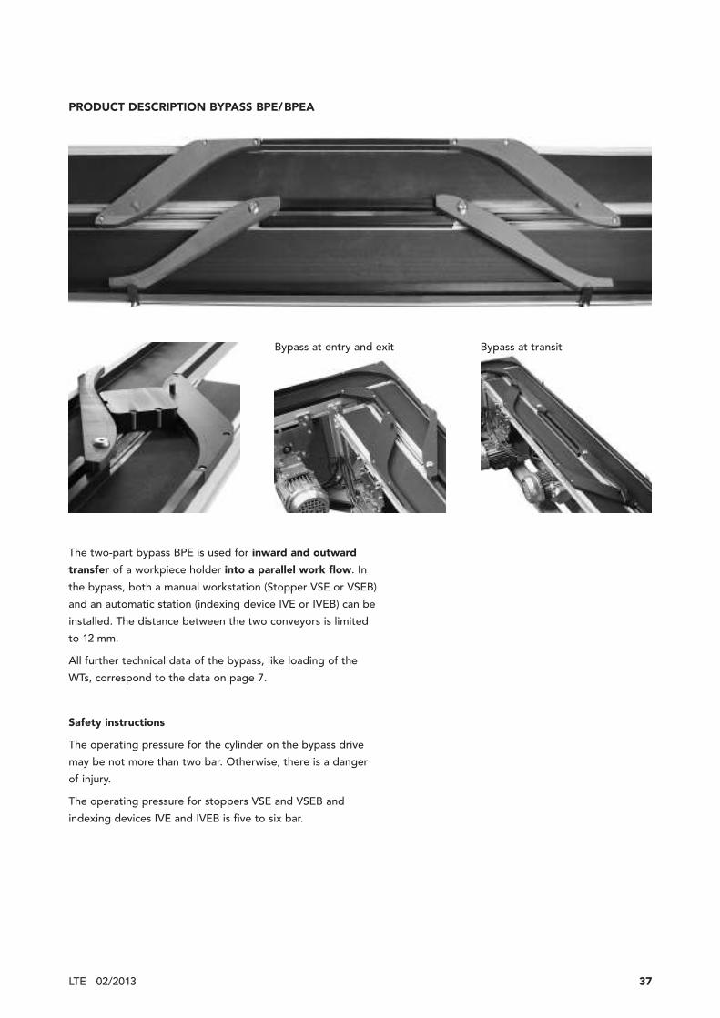
PRODUCT DESCRIPTION BYPASS BPE/BPEA
The two-part bypass BPE is used for inward and outward
transfer of a workpiece holder into a parallel work flow. In
the bypass, both a manual workstation (Stopper VSE or VSEB)
and an automatic station (indexing device IVE or IVEB) can be
installed. The distance between the two conveyors is limited
to 12 mm.
All further technical data of the bypass, like loading of the
WTs, correspond to the data on page 7.
Safety instructions
The operating pressure for the cylinder on the bypass drive
may be not more than two bar. Otherwise, there is a danger
of injury.
The operating pressure for stoppers VSE and VSEB and
indexing devices IVE and IVEB is five to six bar.
Bypass at entry and exit Bypass at transit

38 02/2013 LTE
BYPASS LEFT BPE/BPEA - DIMENSIONS
3.5
F11
.5
65
4014
16
E
D
A
12
A
B
12
F
C
Type BPE/BPEA-105 BPE/BPEA-140 BPE/BPEA-185 BPE/BPEA-250
for TB-105 for TB-140 for TB 185 for TB-250
A [mm] 105 140 185 250
B [mm] 332 317 426 669.6
C [mm] 3 28 9 10
D [mm] 245 215 246 340
E [mm] 290 245 307 490
F [mm] 111 146 191 256
Typ Ref. No.
Bypass left without drive for TB-105, BPE 54564
Bypass left with drive for TB-105, BPEA 54632
Bypass left without drive for TB-140, BPE 54568
Bypass left with drive for TB-140, BPEA 54567
Bypass left without drive for TB-185, BPE 54572
Bypass left with drive for TB-185, BPEA 54571
Bypass left without drive for TB-250, BPE 56361
Bypass left with drive for TB-250, BPEA 56359
CAD Data

39LTE 02/2013
Typ Ref. No.
Bypass right without drive for TB-105, BPE 54494
Bypass right with drive for TB-105, BPEA 54493
Bypass right without drive for TB-140, BPE 54566
Bypass right with drive for TB-140, BPEA 54565
Bypass right without drive for TB-185, BPE 54570
Bypass right with drive for TB-185, BPEA 54569
Bypass right without drive for TB-250, BPE 56360
Bypass right with drive for TB-250, BPEA 56358
BYPASS RIGHT BPE / BPEA - DIMENSIONS
B
E
D
12 26
F
30
54
F
65 3.5
40 14
11.5
C
AA
12
Type BPE/BPEA-105 BPE/BPEA-140 BPE/BPEA-185 BPE/BPEA-250
for TB-105 for TB-140 for TB 185 for TB-250
A [mm] 105 140 185 250
B [mm] 332 317 426 669.6
C [mm] 3 28 9 10
D [mm] 245 215 246 340
E [mm] 290 245 307 490
F [mm] 111 146 191 256
CAD Data

40 02/2013 LTE
PRODUCT DESCRIPTION TRANSFER GATE WEE
The transfer gate WEE is used to distribute workpiece hold-
ers from one conveyor to two conveyors (inward transfer
gate) or from two conveyors to one conveyor (outward trans-
fer gate).
At the inward end, stoppers are used (not included in the
scope of delivery, see options).
All further technical data of the transfer gate, like loading of
the WTs, correspond to the data on page 7.
Safety instructions
The operating pressure for the cylinder on the transfer gate
may be not more than two bar. Otherwise, there is a danger
of injury.

41LTE 02/2013
TRANSFER GATE WEE - DIMENSIONS
25.6
14 40 46
11
3.3
B A B
C
BA
D
16
E
179.7
E
Type WEE-105 for TB-105 WEE-140 for TB-140 WEE-185 for TB 185
A chassis [mm] 105 140 185
B [mm] 58 117.5 133
C [mm] 52.5 70 92.5
D [mm] 43.3 66.1 92.1
E [mm] 52 67.9 67.9
Ref. No.
54789 54790 54791
CAD Data

42 02/2013 LTE
PRODUCT DESCRIPTION INDEXING DEVICE IVE
The indexing device IVE is used for assembly and process
tasks which require excellent workpiece positioning accuracy.
In the indexing device, the workpiece holder WTE is posi-
tioned with a repeatability of ± 0.05 mm and lifted slightly
to reduce conveyor belt wear.
At a maximum belt speed of 19.9 m/min, change-over time is
0.35 seconds with the smallest work-piece holder.
Since installation requires no additional drilling or milling on
the chassis, the position of the indexing device can easily be
adjusted even in a later phase.

43LTE 02/2013
INDEXING DEVICE IVE - DIMENSIONS
E
11.5
63.4
–64.6
15.7 A
43.1
–44.3
73.4
–74.6
BC
min
.D
55
63
Type IVE for TB-105 IVE for TB-140 IVE for TB 185 IVE for TB-250
A chassis [mm] 105 140 185 250
B [mm] 34 51.5 74 106.5
C [mm] 49 66.5 89 121
D [mm] 113 148 193 258
E [mm] 80 115 160 225
Ref. No.
All widths 49613
CAD Data

44 02/2013 LTE
PRODUCT DESCRIPTION INDEXING DEVICE IVEB
The indexing device IVEB is specially designed for use in the
bypass BPE. The stoppers acting from above take into
account the minimum distance of only 12 mm between the
two conveyor belts.

45LTE 02/2013
INDEXING DEVICE IVEB - DIMENSIONS
D
B
34
29
C m
in.
F
E
29
169
7
101.
7–
103
.7 49.
7
36
0–
11
AA 12
11.5
63
.4–
64
.6G
Type IVEB for TB-105 IVEB for TB-140 IVEB for TB 185 IVEB for TB-250
A chassis [mm] 105 140 185 250
B [mm] 34 51.5 74 106.5
C [mm] 49 66.5 89 121
D [mm] 149 184 229 294
E [mm] 106 150.5 198 315.5
F [mm] 25 32.5 35 87.5
G [mm] 80 115 160 225
Ref. No.
Indexing device for bypass IVEB right 54492
Indexing device for bypass IVEB left 54633
Indexing device IVEB right
Indexing device IVEB left
Indexing device IVEB left
Indexing device IVEB right
CAD Data

46 02/2013 LTE
PRODUCT DESCRIPTION POSITIONING UNIT PVE
Positioning unit PVE is used when application of a high force
to the workpiece has to be realized in addition to high posi-
tioning accuracy in assembly and processing operations (press
and screw operations).
PThe repeatability accuracy is ± 0.05 mm.
During positioning, the workpiece support WTE rests on the
anvil, which must be supported from below (not connected to
the chassis). The belt is lowered in the positioning device.
The maximum permissible prsessure is 14 N/mm2.

47LTE 02/2013
POSITIONING UNIT PVE - DIMENSIONS
63
.4–6
4.6
73
.4–7
4.6
11.5 A
E
D
C m
in.
G
H
30
30
F
B
40
14.5
163
0
15.7
35
63
1.2
N m
in.
40
Type PVE-105 for TB-105 PVE-140 for TB-140 PVE-185 for TB 185 PVE-250 for TB-250
A chassis [mm] 105 140 185 250
B [mm] 34 51.5 74 106.5
C [mm] 49 66.5 89 121
D [mm] 113 148 193 258
E [mm] 106 150.5 198 315.5
F [mm] 25 32.5 35 87.5
G [mm] 80 115 160 225
H [mm] 40 57.5 80 112.5
I [mm] 103 138 183 248
J [mm] 39 74 119 184
K [mm] 100 115 160 225
L [mm] 70 85 130 87.5
M [mm] 51.5 69 91.5 124
N [mm] 240 302 372 522
M
K
15L
=I
32 J
12
Ø 9
3.5
M6M6
8
Ref. No..
55131 55132 55133 56507
CAD Data

48 02/2013 LTE
POSITIONING UNIT PVE INFORMATION FOR THE DESIGNER
X N Y
L
L
L
YX P
L
X N Y
L
c
c
BKE
BKE
R3
T
SR5
A
Z Z
Z – Z
Conveyor without gliding plateLc see calculation formula for chassis
Conveyor with gliding plateLc see calculation formula for chassisN see page 47 (type of chassis without
gliding plate)X customer-specific lengthY customer-specific length
Conveyor with gliding plateLc see calculation formula for chassisP project-specific length for PVE in series
(type of chassis without gliding plate)X customer-specific lengthY customer-specific length
Belt coupling without gliding plateLBKE see calculation formula for chassis
Belt coupling with gliding plateLBKE see calculation formula for chassisN see page 47 (type of chassis without
gliding plate)X customer-specific lengthY customer-specific length
Specification for the milled edge
Specification for the gliding plate
Type TB-105 TB-140 TB-185 TB-250
A 105 140 185 250
S 77 112 157 222
T 125 140 185 250
CAD Data

49LTE 02/2013
7434.5
16.2
63
30
9
Ø8
4633
3346
14.529 6
36
93
9.5
Ø8
Stopper VSE Ref. No.
Stopper VSEB Ref. No.
Holder for proximity switch HNEB Ref. No.
TRANSFER SYSTEM LTE ACCESSORIES
VSEB right 54601
VSEB left 54581
45
M8x1
Proximity switch pluggable (sensing distance 4 mm) Ref. No.
M8 x1 508845
49612
max. radial force F = 135 N at 5 bar
Stroke 10
Stopper left
max. radial force F = 125 N at 5 bar
Stopper right
Stroke 10
Ø 8.5
8.6
3
76
0–1
116
M8 x1 54634

50 02/2013 LTE
TRANSFER SYSTEM LTE ACCESSORIES
Ø3
.5
22
M8
x1
2000
M8 x1 508848
With one-side angled socket for proximity switch 3-pin,
highly flexible, screwable M8 x 1
5 m 504929
10 m 507529
Proximity switch (sensing distance 2 mm) Ref. No.
Cable Ref. No.
14
0.250.25 11.7511.75
L = 2000 mm 49897
Lateral guide black, antistatic Ref. No.
More accessories under section conveyors accessories.

51LTE 02/2013

more than technology
MONTECH AG
Gewerbestrasse 12
CH-4552 Derendingen
Fon +41 32 681 55 00
Fax +41 32 682 19 77
www.montech.com