
OPERATING INSTRUCTIONS LTE COMPONENTS - … · OPERATING INSTRUCTIONS LTE COMPONENTS ... Operating...
158
OPERATING INSTRUCTIONS LTE COMPONENTS Single-belt Transfer System BA-100056 English Edition 12/2007
Transcript of OPERATING INSTRUCTIONS LTE COMPONENTS - … · OPERATING INSTRUCTIONS LTE COMPONENTS ... Operating...

OPERATING INSTRUCTIONS
LTE COMPONENTS
Single-belt Transfer System
BA-100056 English Edition 12/2007

Operating Instructions Single-belt Transfer System LTE®
1
Table of Contents
1. Important Information__________________________________________________________ 9 1.1. Manufacturer's Declaration ______________________________________________________ 9 1.2. Product Description and Use_____________________________________________________ 9 1.3. Factors Reducing Service Life ____________________________________________________ 9 1.4. Safety Instructions______________________________________________________________ 9 1.5. Additional Information __________________________________________________________ 9 1.6. Application Scope of the Operating Instructions __________________________________ 11 1.7. Technical Data ________________________________________________________________ 11 1.8. Safety Instructions_____________________________________________________________ 11
2. Workpiece Holder WTE________________________________________________________ 12 2.1. Exploded Views / Spare Parts Lists ______________________________________________ 12 2.1.1. Workpiece holder WTE, version A and B _________________________________________ 12 2.1.2. Spare parts list, version A and B ________________________________________________ 12
3. Conveyor TB/TBD_____________________________________________________________ 13 3.1. Technical data TB/TBD/BPBE ___________________________________________________ 13 3.1.1. Mechanical setup _____________________________________________________________ 13 3.1.2. Electrical connections__________________________________________________________ 14 3.1.3. Direction of travel of the conveyor belt __________________________________________ 15 3.1.4. Setting the required pretension of the conveyor belt ______________________________ 15 3.1.5. Moving the drive unit on the chassis_____________________________________________ 16 3.1.6. Tracking of the conveyor belt___________________________________________________ 16 3.1.7. Changing the conveyor speed __________________________________________________ 18 3.1.8. Procedure for changing the chain sprocket _______________________________________ 19 3.1.9. Procedure for changing the gear motor__________________________________________ 19 3.1.10. Technical data of the conveyor belt _____________________________________________ 20 3.1.11. Replacing an endless belt ______________________________________________________ 20 3.1.12. Replacing belts by “welding” their ends _________________________________________ 20 3.2. Maintenance __________________________________________________________________ 20 3.2.1. Repairs ______________________________________________________________________ 21 3.2.2. Replacing the self-aligning ball bearings / drive rollers _____________________________ 21

Operating Instructions Single-belt Transfer System LTE®
2
3.3. Exploded Views / Spare Parts Lists ______________________________________________ 22 3.3.1. TB / TBD conveyor with horizontal drive unit _____________________________________ 22 3.3.2. Spare parts list TB / TBD with horizontal drive unit________________________________ 23 3.3.3. Conveyor TB / TBD with vertical drive unit _______________________________________ 24 3.3.4. Spare parts list TB / TBD with vertical drive unit __________________________________ 25 3.3.5. TB conveyor end with diverter roller, single-belt __________________________________ 26 3.3.6. Spare parts list TB conveyor end with diverter roller, single-belt ____________________ 26 3.3.7. TBD conveyor end with diverter rollers, twin-belt _________________________________ 27 3.3.8. Spare parts list TBD conveyor end with diverter roller, twin-belt____________________ 27 3.3.9. Motor support for vertical drive ________________________________________________ 28 3.3.10. Spare parts list motor support for vertical drive (56531) ___________________________ 28 3.3.11. TB / TBD with horizontal drive unit______________________________________________ 29 3.3.12. Spare parts list TB / TBD with horizontal drive unit________________________________ 29 3.3.13. TB / TBD with vertical drive unit ________________________________________________ 30 3.3.14. Spare parts list TB / TBD with vertical drive unit __________________________________ 30 3.3.15. Side covers TB / TBD horizontal ________________________________________________ 31 3.3.16. Spare parts list side covers TB / TBD horizontal (54888) ___________________________ 31 3.3.17. Side covers TB / TBD vertical___________________________________________________ 32 3.3.18. Spare parts list side covers TB / TBD vertical (54889)______________________________ 32 3.3.19. Side cover long, pre-assembled ________________________________________________ 33 3.3.20. Spare parts list side cover long, horizontal (44873)/ vertical (44875) _________________ 33 3.3.21. Side cover short, pre-assembled________________________________________________ 34 3.3.22. Spare parts list side cover long, horizontal (44874)/ vertical (44876) _________________ 34 3.3.23. TB diverter roller drive ________________________________________________________ 35 3.3.24. Spare parts list TB diverter roller drive __________________________________________ 35 3.3.25. TBD diverter roller drive _______________________________________________________ 36 3.3.26. Spare parts list TBD diverter roller drive _________________________________________ 36
4. Bypass Conveyor BPBE _______________________________________________________ 37 4.1. Technical Data BPBE __________________________________________________________ 37 4.1.1. Setting the required pretension of the conveyor belt______________________________ 37 4.2. Exploded Views / Spare Parts Lists ______________________________________________ 38 4.2.1. Bypass conveyor BPBE with horizontal drive unit _________________________________ 38 4.2.2. Spare parts list BPBE horizontal with drive unit ___________________________________ 39 4.2.3. BPBE drive unit horizontal _____________________________________________________ 40

Operating Instructions Single-belt Transfer System LTE®
3
4.2.4. Spare parts list BPBE drive unit horizontal________________________________________ 40 4.2.5. BPBE side cover ______________________________________________________________ 41 4.2.6. Spare parts list side BPBE covers (56943) ________________________________________ 42 4.2.7. Side cover long, for bypass, pre-assembled ______________________________________ 43 4.2.8. Spare parts list side cover long (55141) __________________________________________ 43 4.2.9. Side cover short to bypass, pre-assembled _______________________________________ 44 4.2.10. Spare parts list side cover short (55142)__________________________________________ 44 4.2.11. Side cover right, pre-assembled ________________________________________________ 45 4.2.12. Spare parts list side cover right (55143) __________________________________________ 45 4.2.13. Side cover left, pre-assembled__________________________________________________ 46 4.2.14. Spare parts list side cover left (55144) ___________________________________________ 46 4.2.15. BPBE diverter rollers drive _____________________________________________________ 47 4.2.16. Spare parts list BPBE diverter rollers drive _______________________________________ 47
5. Conveyor Coupling BKE _______________________________________________________ 48 5.1. Commissioning________________________________________________________________ 48 5.1.1. Setting the required pretension of the conveyor belt ______________________________ 48 5.1.2. Tracking of the conveyor belt___________________________________________________ 49 5.2. Conveyor Belt_________________________________________________________________ 49 5.2.1. Technical data of the conveyor belt _____________________________________________ 49 5.2.2. Replacing an endless belt on the coupling conveyor _______________________________ 49 5.2.3. Replacing belts by “welding” their ends _________________________________________ 49 5.3. Maintenance / Repairs _________________________________________________________ 50 5.3.1. Replacing the synchronous belt _________________________________________________ 50 5.3.2. Replacing the drive rollers on the traction conveyor _______________________________ 51 5.3.3. Replacing the drive rollers on the single-belt coupling conveyor ____________________ 52 5.3.4. Replacing the drive rollers on the twin-belt coupling conveyor______________________ 53 5.4. Maintenance __________________________________________________________________ 54 5.5. Repairs_______________________________________________________________________ 54 5.6. Exploded Views / Spare Parts Lists ______________________________________________ 55 5.6.1. Conveyor coupling TB/TB and TB/TBD___________________________________________ 55 5.6.2. Spare parts list conveyor coupling TB/TB and TB/TBD _____________________________ 55 5.6.3. BKE conveyor end with diverter roller, single-belt _________________________________ 56 5.6.4. Spare parts list BKE conveyor end TB/TB with diverter roller, single-belt_____________ 56 5.6.5. BKE conveyor end with diverter roller, twin belt __________________________________ 57
Operating Instructions Single-belt Transfer System LTE®
4
5.6.6. Spare parts list BKE conveyor end TBD/TB with diverter roller, twin-belt ____________ 57 5.6.7. Conveyor coupling for TB/TB___________________________________________________ 58 5.6.8. Spare parts list conveyor coupling for TB/TB with diverter roller, single-belt _________ 59 5.6.9. Conveyor coupling for TBD/TB _________________________________________________ 60 5.6.10. Spare parts list conveyor coupling for TBD/TB with diverter roller, twin-belt _________ 61 5.6.11. End piece left for TB/TBD______________________________________________________ 62 5.6.12. Spare parts list end piece left for TB/TBD (55188) ________________________________ 62 5.6.13. End piece right for TB/TBD ____________________________________________________ 63 5.6.14. Spare parts list end piece right for TB/TBD (55189) _______________________________ 63 5.6.15. End piece right for BKE________________________________________________________ 64 5.6.16. Spare parts list end piece right for BKE (55190) __________________________________ 64 5.6.17. End piece left for BKE _________________________________________________________ 65 5.6.18. Spare parts list end piece left for BKE (55191)____________________________________ 65
6. Fixed Curve 90° KFE__________________________________________________________ 66 6.1. Use__________________________________________________________________________ 66 6.2. Commissioning _______________________________________________________________ 66 6.2.1. Curve fixed 90° KFE 105, 140, 185 and 250, version M ____________________________ 66 6.2.2. Curve fixed 90° KFE 105, 140, 185 and 250, version E _____________________________ 68 6.3. Exploded Views / Spare Parts Lists ______________________________________________ 70 6.3.1. Fixed curve 90° KFE 105, 140, 185, and 250, version M____________________________ 70 6.3.2. Spare parts list fixed curve KFE, version M_______________________________________ 70 6.3.3. Fixed curve 90° KFE 105, 140, 185, and 250, version E ____________________________ 71 6.3.4. Spare parts list fixed curve KFE, version E _______________________________________ 71 6.3.5. Connection 90° for KFE, version M______________________________________________ 72 6.3.6. Spare parts list connection 90° for KFE, version M (49628) _________________________ 72 6.3.7. Connection 90° for KFE, version E ______________________________________________ 73 6.3.8. Spare parts list connection 90° for KFE, version E_________________________________ 73
7. Movable Curve 90° KBEA/KBE ________________________________________________ 74 7.1. Use__________________________________________________________________________ 74 7.2. Technical Data ________________________________________________________________ 74 7.2.1. Changeover times ____________________________________________________________ 74 7.3. Commissioning _______________________________________________________________ 75 7.3.1. Setup of curve with drive (outward transfer) and the necessary accessories __________ 75
Operating Instructions Single-belt Transfer System LTE®
5
7.3.2. Setup of curve without drive (inward transfer) and the necessary accessories _________ 76 7.3.3. Checking and setting the drive unit _____________________________________________ 77 7.3.4. Checking and setting the bearings ______________________________________________ 78 7.3.5. Flowchart for curve with drive (outward transfer)__________________________________ 79 7.3.6. Flowchart for curve with drive (inward transfer) ___________________________________ 81 7.4. Maintenance and Repairs_______________________________________________________ 83 7.4.1. Replacing the drive cylinder ____________________________________________________ 83 7.4.2. Replacing the drive unit________________________________________________________ 84 7.4.3. Checking and setting the swivel angle ___________________________________________ 85 7.5. Exploded Views / Spare Parts Lists ______________________________________________ 87 7.5.1. Movable curve with drive ______________________________________________________ 87 7.5.2. Spare parts list movable curve with drive_________________________________________ 88 7.5.3. Movable curve without drive ___________________________________________________ 89 7.5.4. Spare parts list movable curve without drive _____________________________________ 90 7.5.5. Drive for curve________________________________________________________________ 91 7.5.6. Spare parts list drive for curve (54502) ___________________________________________ 92 7.5.7. Bearing mount for curve _______________________________________________________ 93 7.5.8. Spare parts list bearing mount for curve (54531) __________________________________ 93 7.5.9. Stop for movable curve and bypass _____________________________________________ 94 7.5.10. Spare parts list stop for movable curve and bypass (54630) ________________________ 94
8. Rotary Diverter UR-180°_______________________________________________________ 95 8.1. Use __________________________________________________________________________ 95 8.2. Safety Instructions_____________________________________________________________ 95 8.3. Commissioning________________________________________________________________ 95 8.3.1. Electrical connections__________________________________________________________ 95 8.3.2. Flowchart for UR (key) _________________________________________________________ 96 8.4. Maintenance and Repairs_______________________________________________________ 98 8.4.1. Replacing the conveyor disc ____________________________________________________ 98 8.4.2. Replacing the diverter rollers ___________________________________________________ 99 8.4.3. Replacing the spur wheel back-geared motor____________________________________ 100 8.4.4. Replacing the sliding hub _____________________________________________________ 101 8.4.5. Adjusting the sliding hub______________________________________________________ 101 8.5. Exploded Views / Spare Parts Lists _____________________________________________ 102 8.5.1. Rotary diverter 180° __________________________________________________________ 102

Operating Instructions Single-belt Transfer System LTE®
6
8.5.2. Spare parts list rotary diverter 90° _____________________________________________ 103
9. Bypass BPEA/BPE ___________________________________________________________ 105 9.1. Use_________________________________________________________________________ 105 9.2. Technical Data _______________________________________________________________ 105 9.2.1. Changeover times ___________________________________________________________ 105 9.3. Commissioning ______________________________________________________________ 106 9.3.1. Setup of bypass with drive (inward transfer) and the necessary accessories _________ 106 9.3.2. Setup of bypass without drive (outward transfer) and the necessary accessories_____ 107 9.3.3. Settings Bypass with drive right and left ________________________________________ 108 9.3.4. Flowchart for bypass with drive (outward transfer) _______________________________ 109 9.3.5. Flowchart for bypass without drive (inward transfer) _____________________________ 111 9.3.6. Flowchart for bypass with drive (inward transfer) ________________________________ 113 9.4. Maintenance and Repairs _____________________________________________________ 115 9.4.1. Replacing the drive cylinder___________________________________________________ 115 9.4.2. Checking and setting the swivel angle__________________________________________ 116 9.4.3. Replacing the drive unit ______________________________________________________ 117 9.5. Exploded Views / Spare Parts Lists _____________________________________________ 118 9.5.1. Bypass with drive ____________________________________________________________ 118 9.5.2. Spare parts list bypass right and left with drive _________________________________ 119 9.5.3. Bypass without drive _________________________________________________________ 120 9.5.4. Spare parts list bypass right and left without drive _______________________________ 121 9.5.5. Drive for bypass _____________________________________________________________ 122 9.5.6. Spare parts list drive for bypass (54486) ________________________________________ 123 9.5.7. Bearing for bypass ___________________________________________________________ 124 9.5.8. Spare parts list bearing for bypass (54496)______________________________________ 124 9.5.9. Spare parts list stop for bypass (54630)_________________________________________ 124
10. Transfer Gate WEE __________________________________________________________ 125 10.1. Use_________________________________________________________________________ 125 10.2. Technical Data _______________________________________________________________ 125 10.2.1. Changeover times ___________________________________________________________ 125 10.3. Commissioning ______________________________________________________________ 125 10.3.1. Setup of inward transfer gate WEE and the necessary accessories _________________ 125 10.3.2. Setup of outward transfer gate WEE and the necessary accessories________________ 126
Operating Instructions Single-belt Transfer System LTE®
7
10.3.3. Checking and setting the drive unit ____________________________________________ 127 10.3.4. Flowchart for transfer gate (inward transfer)_____________________________________ 128 10.3.5. Flowchart for transfer gate (outward transfer) ___________________________________ 130 10.4. Maintenance and Repairs______________________________________________________ 132 10.4.1. Replacing the drive cylinder ___________________________________________________ 132 10.4.2. Replacing the drive unit_______________________________________________________ 132 10.4.3. Checking and setting the swivel angle __________________________________________ 133 10.5. Exploded Views / Spare Parts Lists _____________________________________________ 134 10.5.1. Transfer gate ________________________________________________________________ 134 10.5.2. Spare parts list transfer gate __________________________________________________ 135 10.5.3. Spare parts list drive for transfer gate (54502) ___________________________________ 135
11. Indexing Device IVE and IVEB_________________________________________________136 11.1. Use _________________________________________________________________________ 136 11.2. Commissioning_______________________________________________________________ 136 11.2.1. Assembling and setting the indexing device IVEB ________________________________ 136 11.2.2. Installation and setting of indexing device IVE ___________________________________ 141 11.2.3. Flowchart for indexing device IVEB/IVE _________________________________________ 141 11.3. Exploded Views / Spare Parts Lists _____________________________________________ 143 11.3.1. Indexing device IVE __________________________________________________________ 143 11.3.2. Spare parts list indexing device IVE (49613) _____________________________________ 143 11.3.3. Indexing device IVEB right and left _____________________________________________ 144 11.3.4. Spare parts list indexing device IVEB right (54492) _______________________________ 144 11.3.5. Spare parts list indexing device IVEB left (54633) ________________________________ 145
12. Positioning Device PVE_______________________________________________________146 12.1. Use _________________________________________________________________________ 146 12.2. Technical Data _______________________________________________________________ 146 12.2.1. Maximum torque_____________________________________________________________ 146 12.3. Commissioning_______________________________________________________________ 148 12.3.1. Mounting and setting positioning device PVE ___________________________________ 148 12.3.2. Flowchart for positioning device PVE ___________________________________________ 152 12.4. Exploded Views / Spare Parts Lists _____________________________________________ 154 12.4.1. Positioning device PVE _______________________________________________________ 154 12.4.2. Spare parts list positioning device PVE _________________________________________ 154

Operating Instructions Single-belt Transfer System LTE®
8
12.4.3. Support with belt stroke cylinder ______________________________________________ 155 12.4.4. Spare parts list support with belt stroke cylinder ________________________________ 155
13. Environmental Friendliness and Disposal ______________________________________ 156

Operating Instructions Single-belt Transfer System LTE®
9
1. Important Information
Conveyors as component assemblies are not subject to the EU Declaration of Conformity (pursuant to MRL Appendix II)
EU Declaration of Conformity (pursuant to MRL Appendix II)
1.1. Manufacturer's Declaration
Regulations and standards considered: – Machine Directive 89/392/EEC, 91/368/EEC, – Low Voltage Directive 73/23/EEC, EMC Directive 89/336/EEC, EN 50081-2, EN 50082-2, 91/236/EEC and 92/31/EEC Manufacturer: Montech AG, Gewerbestrasse 12 CH–4552 Derendingen Tel. +41 32 681 55 00, Fax +41 32 682 19 77
1.2. Product Description and Use
The single-belt transfer system is used for the transport of workpiece holders (WTE) in the assembly industry. The single-belt transfer system used the Montech conveyor (TB) as a basis. Under no circumstances must the product-specific ratings listed on the name plate be exceeded.
1.3. Factors Reducing Service Life
– Direct light from UV lamps – Queuing when carrying sharp-edged work pieces. – Operation in air containing smoke, dust, vapor, or solvents.
1.4. Safety Instructions
The safety instructions, in particular those relating to electrical connections, must be followed in all phases of commissioning, operation and during maintenance and service work. Failure to follow these instructions is considered a misuse of the transport system and its components. Operating a conveyor in an explosive atmosphere (flammable gases, vapors, or dust) can result in their combustion and shall be avoided. Never perform service or setting work on your own. In all cases, there must be a second person present who can shut of the main power and administer first aid, if necessary. Moving the electromechanical drive unit on the chassis, as well as removing the mechanical safety guards must ONLY be performed when the conveyor is disconnected from the main power supply.
1.5. Additional Information
These operating instructions are designed to ensure the safe and proper installation of the single-belt transfer system. If you need information in an individual case, please contact the manufacturer.

Operating Instructions Single-belt Transfer System LTE®
10
Additional information, e.g. on mounting the lateral guides, etc., can be found in the TB Assembly Instructions. These documents are available from our home page, www.montech.com. Additional copies can be provided free-of-charge. When ordering operating instructions, always include the series number or the order number. This document is available from our home page, www.montech.com. Description Nameplate Conveyors
Description Nameplate Other Components Item number Product name Serial number Montech AG Senior Management
U. D .Wagner / C. Wullschleger
ENI-5EE

Operating Instructions Single-belt Transfer System LTE®
11
1.6. Application Scope of the Operating Instructions
We always adapt our products to the state-of-the-art and new findings from practical applications. Therefore, the operating instructions are updated to match the product modifications. Each operating instruction has an item number, e.g., BA-100056. The item number and edition are on the cover sheet.
1.7. Technical Data
Ambient temperature [°C] 10 – 40
Relative air humidity 5% - 85% (without formation of condensation)
Air purity level normal shop air
Sound pressure level [dBA] < 70
Positioning accuracy WTE in IVE and IVEB [mm] ±0.05
Workpiece carrier sizes WTE [mm]
80x80 (weight 170g) 115x115 (weight 360g) 160x160 (weight 690g) 225x225 (weight 1660g)
Max. weight WTE with load:
For WTE 80x80/115x115/160x160 [kg] 2.5
For WTE 225x225 [kg] 5
Max. torque on WTE in IVE and IVEB [Nm] 5 (at 18m/min)
Max. force of pressure on WTE in IVE and IVEB [N] 120
Operating pressure [Nm] See Safety Instructions
Operating medium 5µM m filtered, oiled or unoiled air, due point < 6°C
Material of workpiece holder WTE Polyethylenterephthalate PET, black
Material of lateral guides Polyethylene PE, black, antistatic
Recommended belt type ENI-5EE, black, antistatic, manufacturer Habasit
1.8. Safety Instructions
The operating pressure for the movable curve, transfer gate, and the bypass must not exceed
2 bar! Otherwise, there is a risk of injuries. Operating pressure for stoppers VSE and VSEB, indexing devices IVE and IVEB is 5-6 bar. According to EN 1050
Operating Instructions Single-belt Transfer System LTE®
12
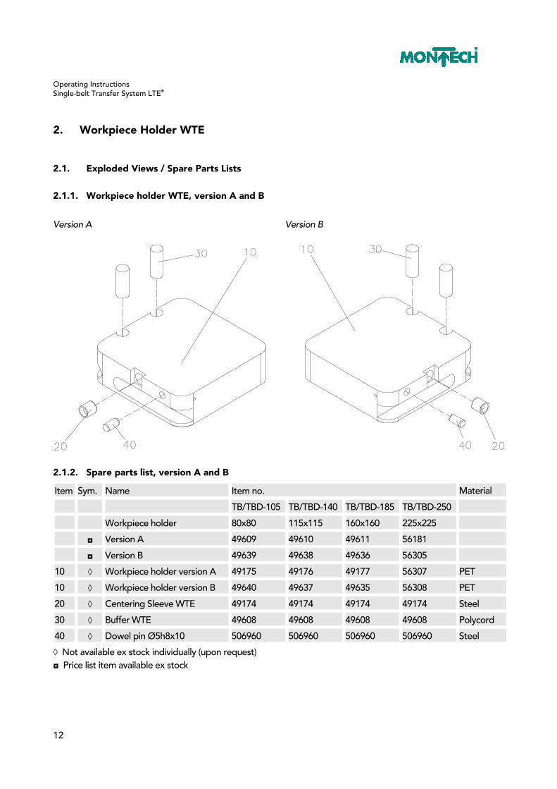
2. Workpiece Holder WTE
2.1. Exploded Views / Spare Parts Lists
2.1.1. Workpiece holder WTE, version A and B
Version A Version B
2.1.2. Spare parts list, version A and B
Item Sym. Name Item no. Material
TB/TBD-105 TB/TBD-140 TB/TBD-185 TB/TBD-250
Workpiece holder 80x80 115x115 160x160 225x225
◘ Version A 49609 49610 49611 56181
◘ Version B 49639 49638 49636 56305
10 ◊ Workpiece holder version A 49175 49176 49177 56307 PET
10 ◊ Workpiece holder version B 49640 49637 49635 56308 PET
20 ◊ Centering Sleeve WTE 49174 49174 49174 49174 Steel
30 ◊ Buffer WTE 49608 49608 49608 49608 Polycord
40 ◊ Dowel pin Ø5h8x10 506960 506960 506960 506960 Steel
◊ Not available ex stock individually (upon request) ◘ Price list item available ex stock

Operating Instructions Single-belt Transfer System LTE®
13
3. Conveyor TB/TBD
3.1. Technical data TB/TBD/BPBE
3.1.1. Mechanical setup
The conveyors are shipped in lengths of up to 3 m. If the total length of a conveyor exceeds the maximum transportation length of 3 m, the components must be reassembled as follows. Chassis length (total, in mm) L � 3000 Lateral guide
Chassis
3000 < L � 6000 Lateral guide Chassis
6000 < L � 9000 Lateral guide Chassis
9000 < L � 12000 Lateral guide Chassis
Svar variable length of lateral guides, min. = 500 mm, max. = 2000 mm Cvar variable chassis length, Cvar max. = 3000 - 60, or 3000 - (2x60) mm
D chassis joint - take apart here for transport (tab connection) Secure the tab connections marked “D” prior to commissioning. The conveyor must be supported at these locations. The drive unit should be mounted near the discharge end of the conveyor. Applications where the drive unit has to be positioned on the infeed side, e.g. because of a lack of space and especially where high loads occur during queuing, should be referred to Montech for evaluation.
Operating Instructions Single-belt Transfer System LTE®
14
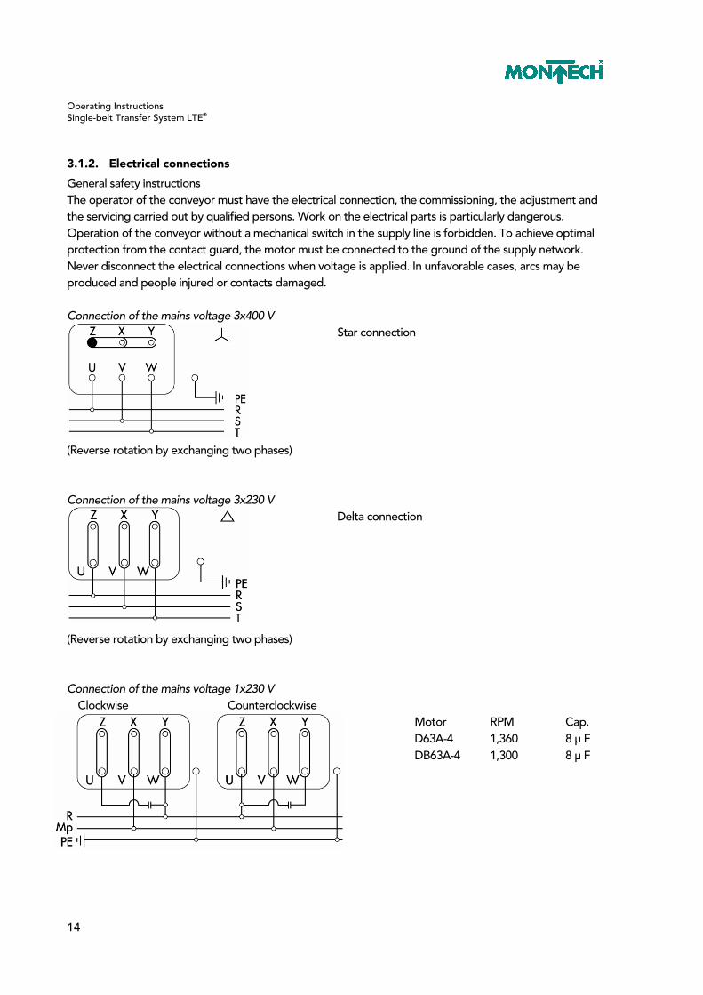
3.1.2. Electrical connections
General safety instructions The operator of the conveyor must have the electrical connection, the commissioning, the adjustment and the servicing carried out by qualified persons. Work on the electrical parts is particularly dangerous. Operation of the conveyor without a mechanical switch in the supply line is forbidden. To achieve optimal protection from the contact guard, the motor must be connected to the ground of the supply network. Never disconnect the electrical connections when voltage is applied. In unfavorable cases, arcs may be produced and people injured or contacts damaged. Connection of the mains voltage 3x400 V
Star connection
(Reverse rotation by exchanging two phases) Connection of the mains voltage 3x230 V
Delta connection
(Reverse rotation by exchanging two phases) Connection of the mains voltage 1x230 V
Clockwise Counterclockwise Motor RPM Cap. D63A-4 1,360 8 µ F DB63A-4 1,300 8 µ F

Operating Instructions Single-belt Transfer System LTE®
15
3.1.3. Direction of travel of the conveyor belt
For belt type SNI-5E , the direction of travel is of no significance. Flexproof weld seam
3.1.4. Setting the required pretension of the conveyor belt
The correct pretension for a conveyor belt is shown on the nameplate attached to the drive unit. For example: 1.2% After the belt has been mounted, two measuring marks (M) must be attached to the top of the belt in the untensioned state in such a way that they have a spacing (L) of e.g. 500 or 1000 mm. When the two tensioning screws (30) are uniformly tightened, the two measuring marks (M) move apart up to the dimension (L) which corresponds to the required pretension. Example for calculating the belt pretension
1.2%verfund1000mmLBei lose ==
(%)100
vLLL necloose
loosetaut ∗+=
mm1012%2.1%100
mm1000mm1000Ltaut =∗+=

Operating Instructions Single-belt Transfer System LTE®
16
3.1.5. Moving the drive unit on the chassis
Procedure: – Switch off the motor. – Loosen screws “250” on the side cover short “20” and the screws on side cover long “10”. – Move the drive unit in the desired position and tighten the four screws “250” on both side covers. Should the belt no longer run centered on the diverter rollers, it should be aligned as explained in section “Tracking of the conveyor belt.”
3.1.6. Tracking of the conveyor belt
The belt must always run centrally over the diverter rollers or nose-bars and drive rollers. Under no circumstances must the edges of the belt project over the ends of the rollers. The position of the belt running over the diverter rollers and nose-bars can be corrected by tightening or slackening the special screws “280” while the belt is running.
Operating Instructions Single-belt Transfer System LTE®
17
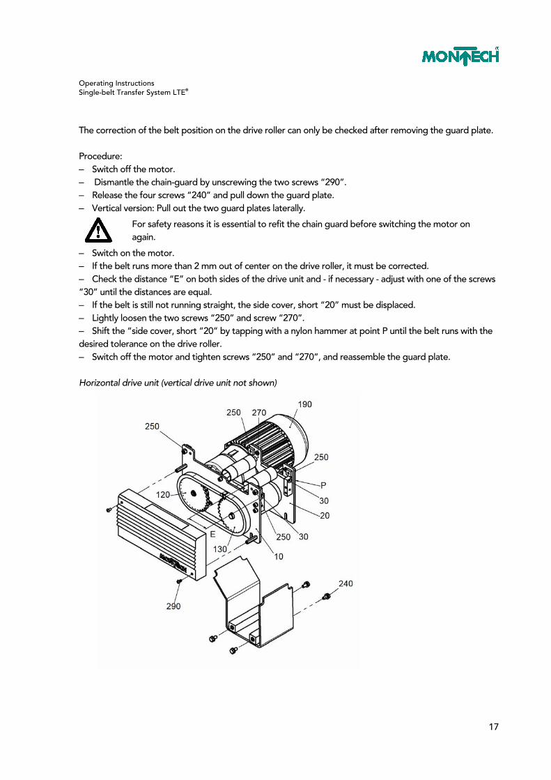
The correction of the belt position on the drive roller can only be checked after removing the guard plate. Procedure: – Switch off the motor. – Dismantle the chain-guard by unscrewing the two screws “290”. – Release the four screws “240” and pull down the guard plate. – Vertical version: Pull out the two guard plates laterally. For safety reasons it is essential to refit the chain guard before switching the motor on
again.
– Switch on the motor. – If the belt runs more than 2 mm out of center on the drive roller, it must be corrected. – Check the distance “E” on both sides of the drive unit and - if necessary - adjust with one of the screws “30” until the distances are equal. – If the belt is still not running straight, the side cover, short “20” must be displaced. – Lightly loosen the two screws “250” and screw “270”. – Shift the “side cover, short “20” by tapping with a nylon hammer at point P until the belt runs with the desired tolerance on the drive roller. – Switch off the motor and tighten screws “250” and “270”, and reassemble the guard plate. Horizontal drive unit (vertical drive unit not shown)

Operating Instructions Single-belt Transfer System LTE®
18
3.1.7. Changing the conveyor speed
The conveying speed can be altered by exchanging the driving sprocket “120” and/or by replacing the gear motor “190.” Chain sprocket “130” must not be changed. Conversion parts for changing the conveyor speed
Motor Gearbox Sprocket
Number of teeth Conveyor speed (m/min.)
Motor type Reduction gear
Z1 Item 120
Z2 Item 130
7.5 G80F / 4D63A-4 18.87:1 15 29
9.5 G80F / 4D63A-4 18.87:1 19 29
11.5 G80F / 4D63A-4 18.87:1 23 29
14.5 G80F / 4D63A-4 18.87:1 29 29
19.9 G80F / 4DB63A-4 7.1:1 15 29
The motors are equipped with heat monitors (130°C).

Operating Instructions Single-belt Transfer System LTE®
19
3.1.8. Procedure for changing the chain sprocket
– Switch off motor and disconnect from mains voltage. – Remove the chain guard by unscrewing the two screws “290”. – To slacken the chain, release the 4 screws “230”. – Open the spring-link “220”. – Release screws “300”. – Pull sprocket “120” off the gear-shaft. – Push the new sprocket “120” onto the gear shaft and align the teeth of “120” and “130” with each other. – Tighten screws “300”. – Fit the chain corresponding to the sprocket combination to “120” and “130”. – Tension the chain by shifting the gear motor and lightly tighten the 4 screws “230”. – The chain has the right tension when the upper strand sags by 1-2 mm when pressed down. – Tighten the 4 screws “230” and fit the chain guard “140”.
3.1.9. Procedure for changing the gear motor
The procedure is the same as for changing the sprocket, except that after removing the driving sprocket “120”, the gear motor is changed. Gearbox type SG-80 is fitted to the “side cover, long” with 4 flange sockets “440”.

Operating Instructions Single-belt Transfer System LTE®
20
3.1.10. Technical data of the conveyor belt
Data pertinent to the conveyor and belt is found on the nameplate attached to the drive unit and must be taken into consideration when ordering replacement belts.
3.1.11. Replacing an endless belt
The installation of endless belts is recommended when the conveyor is easily accessible or when the equipment needed for “welding” prepared end belts is not available. In particular, electrically or pneumatically supplied consumers mounted on the conveyor chassis side opposite to the chain drive, as well as floor stands and table stands, must be removed to replace an endless belt. Procedure: – Switch off motor and disconnect from mains voltage. – Slacken the conveyor belt by alternately loosening the two screws “30”. – Remove the chain guard by removing the two screws “290”. – Loosen 4 screws “240” and pull out guard plate in a downward direction. – Vertical version: Pull out the two guard plates laterally . – Unscrew all remaining screws in the side cover, short “20”; it can be removed and the belt replaced. – Reassemble the drive unit in the reverse order. – For pre-tensioning the belt see the section on “Setting the necessary pretension of the belt”. – To ensure that the belt runs straight, see the section on “Tracking of the conveyor belt”.
3.1.12. Replacing belts by “welding” their ends
Pulling in new belts and “welding” their ends is the preferred method of belt replacement where accessibility to previous operations is severely restricted. A prerequisite for this method of assembly is the availability of belt welding equipment. Exact instructions for the “welding operation” can be obtained when ordering the new belts. Procedure: – Switch off motor and disconnect from mains voltage. – Slacken the conveyor belt by alternately loosening the two screws “30”. – Sever the defective belt and join one end of the old belt to the end of the new belt (e.g. with adhesive tape). – Slowly pulling the old belt automatically pulls the new one through the system. – “Weld” the ends of the new belt according to the manufacturer’s instructions. – For pre-tensioning the belt see the section on “Setting the required pretension of the conveyor belt”. – To ensure that the belt runs straight, see the section on “Tracking of the conveyor belt”.
3.2. Maintenance
Belt conveyors are maintenance free when they are employed in accordance with their purpose and are not exposed to any factors likely to shorten the useful life. The purpose and the factors likely to shorten life are listed in the declaration of conformity. When the belts are exposed to the action of dust, oily air, foreign matter such as metal chips from machine tools, etc., we recommend that they should be regularly cleaned, e.g. once a week, with pure gasoline.

Operating Instructions Single-belt Transfer System LTE®
21
3.2.1. Repairs
The operating instructions contain the necessary spare parts lists and exploded drawings for repairs to the mechanical part of the conveyor. The safety instructions must also be followed. Repairs to the electrical part may be carried out only by the supplier. It is essential to follow the safety instructions for electrical disconnection of components from the mains or from the motor and for subsequent reinstallation.
3.2.2. Replacing the self-aligning ball bearings / drive rollers
When replacing the self-aligning ball bearing “50” or the drive roller “250,” the inner ring and the bearing seat on the drive roller must first be degreased and then adhesively bonded with Loctite 641 or Ergo 4401 (shaft-hub joint). It is essential to allow the adhesive to harden for 24 hours.

Operating Instructions Single-belt Transfer System LTE®
22
3.3. Exploded Views / Spare Parts Lists
3.3.1. TB / TBD conveyor with horizontal drive unit

Operating Instructions Single-belt Transfer System LTE®
23
3.3.2. Spare parts list TB / TBD with horizontal drive unit
Item Name Item no.
TB/TBD-105 TB/TBD-140 TB/TBD-185 TB/TBD-250
10 Chassis aluminum with sliding plate
55388/…. 55389/…. 55390/…. 55391/….
Sliding plate sendzimir-galvanized
54869/0084/…. 54869/0119/…. 54869/0164/…. 54869/0229/….
Sliding plate stainless 54868/0084/…. 54868/0119/…. 54868/0164/…. 54868/0229/….
20 Conveyor end with diverter roller, single-belt
56990 56991 56992 56993
20 Conveyor end with diverter roller, twin-belt
56994 56995 56996 56997
40 Horizontal drive unit single-belt
54332 57996 57997 57998
40 Horizontal drive unit twin-belt
54334 58004 58005 58006
50 G80F/D63A-4 / 18.87:1 510003 510003 510003 510003
50 G80F/DB63A-4 / 7.1:1 510004 510004 510004 510004
60 Sprocket set for gearbox G80F v=7.5/19.9 m/min, z=15
44980 44980 44980 44980
60 Sprocket set for gearbox G80F v=9.5/25.2 m/min, z=19
44981 44981 44981 44981
60 Sprocket set for gearbox G80F v=11.5/30.5 m/min, z=23
44982 44982 44982 44982
60 Sprocket set for gearbox G80F v=14.5/38.4 m/min, z=29
44983 44983 44983 44983
Operating Instructions Single-belt Transfer System LTE®
24
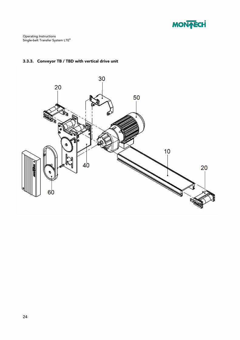
3.3.3. Conveyor TB / TBD with vertical drive unit

Operating Instructions Single-belt Transfer System LTE®
25
3.3.4. Spare parts list TB / TBD with vertical drive unit
Item Name Item no.
TB/TBD-105 TB/TBD-140 TB/TBD-185 TB/TBD-250
10 Chassis aluminum with sliding plate
55388/…. 55389/…. 55390/…. 55391/….
Sliding plate sendzimir-galvanized 54869/0084/…. 54869/0119/…. 54869/0164/…. 54869/0229/….
Sliding plate stainless 54868/0084/…. 54868/0119/…. 54868/0164/…. 54868/0229/….
20 Conveyor end with diverter roller, single-belt
56990 56991 56992 56993
20 Conveyor end with diverter roller, twin-belt
56994 56995 56996 56997
30 Motor support Vertical drive unit
56531 56531 56531 56531
40 Vertical drive unit single-belt
54333 58001 58002 58003
40 Vertical drive unit twin-belt
54335 58007 58008 58009
50 G80F/D63A-4 / 18.87:1 510003 510003 510003 510003
50 G80F/DB63A-4 / 7.1:1 510004 510004 510004 510004
60 Sprocket set for gearbox G80F v=7.5/19.9 m/min, z=15
44980 44980 44980 44980
60 Sprocket set for gearbox G80F v=9.5/25.2 m/min, z=19
44981 44981 44981 44981
60 Sprocket set for gearbox G80F v=11.5/30.5 m/min, z=23
44982 44982 44982 44982
60 Sprocket set for gearbox G80F v=14.5/38.4 m/min, z=29
44983 44983 44983 44983

Operating Instructions Single-belt Transfer System LTE®
26
3.3.5. TB conveyor end with diverter roller, single-belt
3.3.6. Spare parts list TB conveyor end with diverter roller, single-belt
Item Sym. Name Item no. Material
TB-105 TB-140 TB-185 TB-250
◘ Conveyor end, complete 56990 56991 56992 56993 Various
10 ◊ Conveyor end 56918 56917 56916 56915 Aluminum
20 ● Diverter roller, complete 56958 56959 56960 56961 Steel
30 ◘ Conveyor-conveyor elem.,
complete 36546
36546 36546 36546 Steel
● These are wearing parts and available ex stock. ◊ Not available ex stock individually (upon request) ◘ Price list item available ex stock

Operating Instructions Single-belt Transfer System LTE®
27
3.3.7. TBD conveyor end with diverter rollers, twin-belt
3.3.8. Spare parts list TBD conveyor end with diverter roller, twin-belt
Item Sym. Name Item no. Material
TBD-105 TBD-140 TBD-185 TBD-250
◘ Conveyor end, complete 56994 56995 56996 56997 Various
10 ◊ Conveyor end 56918 56917 56916 56915 Aluminum
20 ● Diverter roller, complete 56962 56963 56964 56965 Steel
30 ◘ Conveyor-conveyor elem.,
complete 36546
36546 36546 36546 Steel
● These are wearing parts and available ex stock. ◊ Not available ex stock individually (upon request) ◘ Price list item available ex stock

Operating Instructions Single-belt Transfer System LTE®
28
3.3.9. Motor support for vertical drive
3.3.10. Spare parts list motor support for vertical drive (56531)
Item Sym. Name Item no. Material
TB/TBD-105 - 250
10 ◊ Motor support 56342 Steel
20 ◊ Hex screws M6x12 504386 Steel
30 ◊ Ribbed washer M6. 505255 Steel
40 ◊ Washer M6 504388 Steel
50 ◊ Hex screws M5x12 504351 Steel
60 ◊ Ribbed washer M5. 502365 Steel
70 ◊ Washer M5 504343 Steel
80 ◊ Hex nut M5x0.8d 504903 Steel
◊ Not available ex stock individually (upon request)
Operating Instructions Single-belt Transfer System LTE®
29
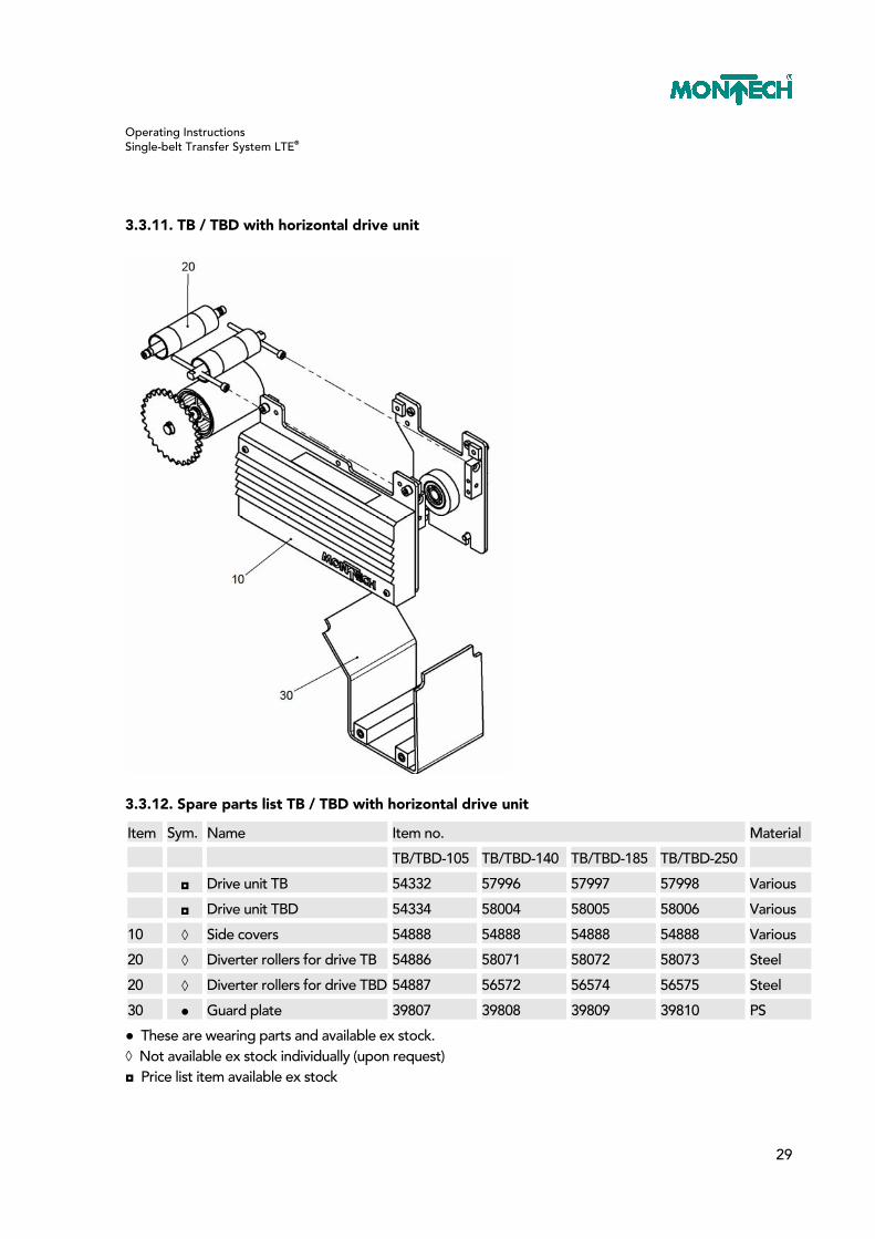
3.3.11. TB / TBD with horizontal drive unit
3.3.12. Spare parts list TB / TBD with horizontal drive unit
Item Sym. Name Item no. Material
TB/TBD-105 TB/TBD-140 TB/TBD-185 TB/TBD-250
◘ Drive unit TB 54332 57996 57997 57998 Various
◘ Drive unit TBD 54334 58004 58005 58006 Various
10 ◊ Side covers 54888 54888 54888 54888 Various
20 ◊ Diverter rollers for drive TB 54886 58071 58072 58073 Steel
20 ◊ Diverter rollers for drive TBD 54887 56572 56574 56575 Steel
30 ● Guard plate 39807 39808 39809 39810 PS
● These are wearing parts and available ex stock. ◊ Not available ex stock individually (upon request) ◘ Price list item available ex stock

Operating Instructions Single-belt Transfer System LTE®
30
3.3.13. TB / TBD with vertical drive unit
3.3.14. Spare parts list TB / TBD with vertical drive unit
Item Sym. Name Item no. Material
TB/TBD-105 TB/TBD-140 TB/TBD-185 TB/TBD-250
◘ Drive unit TB 54333 58001 58002 58003 Various
◘ Drive unit TBD 54335 58007 58008 58009 Various
10 ◊ Side covers 54889 54889 54889 54889 Various
20 ◊ Diverter rollers for drive
TB 54886 58071 58072 58073 Steel
20 ◊ Diverter rollers for drive
TBD 54887 56572 56574 56575 Steel
30 ● Guard plate 55308 58076 58077 58078 PS
● These are wearing parts and available ex stock. ◊ Not available ex stock individually (upon request) ◘ Price list item available ex stock

Operating Instructions Single-belt Transfer System LTE®
31
3.3.15. Side covers TB / TBD horizontal
3.3.16. Spare parts list side covers TB / TBD horizontal (54888)
Item Sym. Name Item no. Material
TB / TBD horizontal
10 ◊ Side cover long, pre-assembled 44873 Steel
20 ◊ Side cover short, pre-assembled 44874 Steel
30 ● Chain guard 45566 Steel
40 ◊ Machine elements 54320 Various
40/10 ◘ T-nut, square 21913 Steel
40/20 ◊ Spacer M4x30 501488 Steel
40/30 ◊ Oval head screw M4x8 504376 Steel
40/40 ◊ Cheese head screws M6x12 504644 Steel
40/50 ◊ Ribbed washer M6 505255 Steel
40/60 ◊ Hex screws M6x12 504386 Steel
40/70 ◊ Washer M6 504388 Steel
● These are wearing parts and available ex stock. ◊ Not available ex stock individually (upon request) ◘ Price list item available ex stock

Operating Instructions Single-belt Transfer System LTE®
32
3.3.17. Side covers TB / TBD vertical
3.3.18. Spare parts list side covers TB / TBD vertical (54889)
Item Sym. Name Item no. Material
TB / TBD - vertical
10 ◊ Side cover long, pre-assembled 44875 Steel
20 ◊ Side cover short, pre-assembled 44876 Steel
30 ● Chain guard 45566 Steel
40 ◊ Machine elements 54321 Various
40/10 ◘ T-nut, square 21913 Steel
40/20 ◊ Spacer M4x30 501488 Steel
40/30 ◊ Oval head screw M4x8 504376 Steel
40/40 ◊ Cheese head screws M6x12 504644 Steel
40/50 ◊ Ribbed washer M6 505255 Steel
40/60 ◊ Hex screws M5x12 504351 Steel
40/70 ◊ Washer M5 504343 Steel
● These are wearing parts and available ex stock. ◊ Not available ex stock individually (upon request) ◘ Price list item available ex stock

Operating Instructions Single-belt Transfer System LTE®
33
3.3.19. Side cover long, pre-assembled
3.3.20. Spare parts list side cover long, horizontal (44873)/ vertical (44875)
Item Sym. Name Item no. Material
horizontal vertical
10 ◊ Side cover, long 44763 44788 Steel
20 ◊ Pressure pad 44789 44789 Steel
30 ● Centering ring 38374 38374 Aluminum
40 ◊ Guide screw 21629 21629 Steel
100 ● Self-aligning bearing 503611 503611 Steel
110 ◊ Cheese head screws
M5x16 503785 503785 Steel
120 ◊ Cheese head screws
M3x12 504371 504371 Steel
130 ◊ Lock washer M3 504374 504374 Steel
140 ◊ Lock washer M5 504345 504345 Steel
● These are wearing parts and available ex stock. ◊ Not available ex stock individually (upon request)

Operating Instructions Single-belt Transfer System LTE®
34
3.3.21. Side cover short, pre-assembled
3.3.22. Spare parts list side cover long, horizontal (44874)/ vertical (44876)
Item Sym. Name Item no. Material
horizontal vertical
10 ◊ Side cover, short 44764 44787 Steel
20 ◊ Pressure pad 44789 44789 Steel
30 ● Centering ring 38374 38374 Aluminum
40 ◊ Guide screw 21629 21629 Steel
100 ● Self-aligning bearing 503611 503611 Steel
110 ◊ Cheese head screws
M5x16 503785 503785 Steel
120 ◊ Cheese head screws
M3x12 504371 504371 Steel
130 ◊ Lock washer M3 504374 504374 Steel
140 ◊ Lock washer M5 504345 504345 Steel
● These are wearing parts and available ex stock. ◊ Not available ex stock individually (upon request)
Operating Instructions Single-belt Transfer System LTE®
35
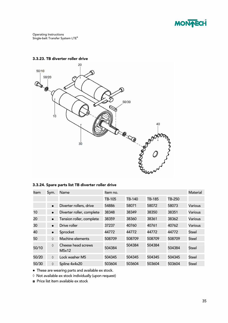
3.3.23. TB diverter roller drive
3.3.24. Spare parts list TB diverter roller drive
Item Sym. Name Item no. Material
TB-105 TB-140 TB-185 TB-250
● Diverter rollers, drive 54886 58071 58072 58073 Various
10 ● Diverter roller, complete 38348 38349 38350 38351 Various
20 ● Tension roller, complete 38359 38360 38361 38362 Various
30 ● Drive roller 37237 40760 40761 40762 Various
40 ● Sprocket 44772 44772 44772 44772 Steel
50 ◊ Machine elements 508709 508709 508709 508709 Steel
50/10 ◊ Cheese head screws
M5x12 504384
504384 504384 504384 Steel
50/20 ◊ Lock washer M5 504345 504345 504345 504345 Steel
50/30 ◊ Spline 4x4x20 503604 503604 503604 503604 Steel
● These are wearing parts and available ex stock. ◊ Not available ex stock individually (upon request) ◘ Price list item available ex stock

Operating Instructions Single-belt Transfer System LTE®
36
3.3.25. TBD diverter roller drive
3.3.26. Spare parts list TBD diverter roller drive
Item Sym. Name Item no. Material
TBD-105 TBD-140 TBD-185 TBD-250
● Diverter rollers, drive 54887 56572 56574 56575 Various
10 ● Diverter roller, complete 55219 55220 55221 55222 Various
20 ● Tension roller, complete 55223 55224 55225 55226 Various
30 ● Drive roller 37237 40760 40761 40762 Various
40 ● Sprocket 44772 44772 44772 44772 Steel
50 ◊ Machine elements 508709 508709 508709 508709 Steel
50/10 ◊ Cheese head screws M5x12 504384 504384 504384 504384 Steel
50/20 ◊ Lock washer M5 504345 504345 504345 504345 Steel
50/30 ◊ Spline 4x4x20 503604 503604 503604 503604 Steel
● These are wearing parts and available ex stock. ◊ Not available ex stock individually (upon request) ◘ Price list item available ex stock

Operating Instructions Single-belt Transfer System LTE®
37
4. Bypass Conveyor BPBE
4.1. Technical Data BPBE
For missing data see chapter on Conveyor.
4.1.1. Setting the required pretension of the conveyor belt
The correct pretension for a conveyor belt is shown on the nameplate attached to the drive unit. For example: 1.2% After the belt has been mounted, two measuring marks (M) must be attached to the top of the belt in the untensioned state in such a way that they have a spacing (L) of e.g. 500 or 1000 mm. When the two tensioning screws (30) are uniformly tightened, the two measuring marks (M) move apart up to the dimension (L) which corresponds to the required pretension. Example for calculating the belt pretension
%2.1vandmm1000LWhen necloose ==
mm1012%2.1%100
mm1000mm1000Ltaut =∗+=
(%)100
vLLL necloose
loosetaut ∗+=
Operating Instructions Single-belt Transfer System LTE®
38
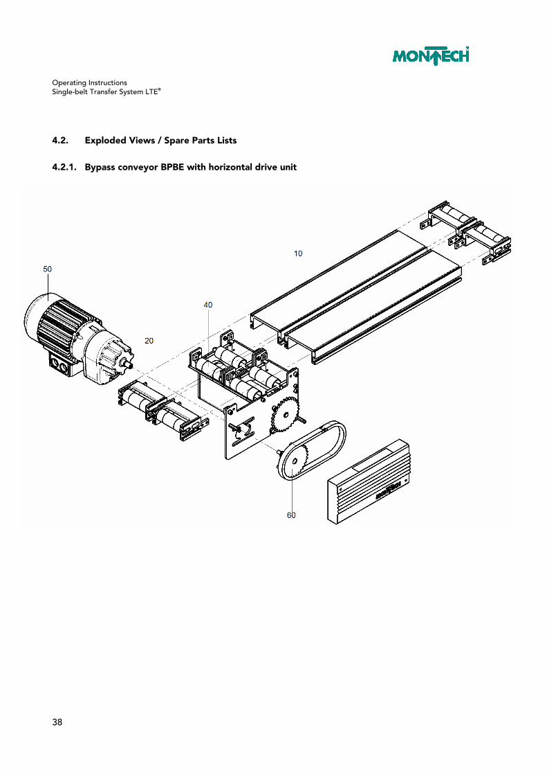
4.2. Exploded Views / Spare Parts Lists
4.2.1. Bypass conveyor BPBE with horizontal drive unit

Operating Instructions Single-belt Transfer System LTE®
39
4.2.2. Spare parts list BPBE horizontal with drive unit
Item Name Item no.
TB-105 TB-140 TB-185 TB-250
10 Chassis aluminum with sliding plate
55388/…. 55389/…. 55390/…. 55391/….
Sliding plate sendzimir-galvanized
54869/0084/…. 54869/0119/…. 54869/0164/…. 54869/0229/….
Sliding plate stainless 54868/0084/…. 54868/0119/…. 54868/0164/…. 54868/0229/….
20 Conveyor end with diverter roller, single-belt
56990 56991 56992 56993
40 Horizontal drive unit single-belt
56907 56908 56909 56910
50 G80F/D63A-4 / 18.87:1 510003 510003 510003 510003
50 G80F/DB63A-4 / 7.1:1 510004 510004 510004 510004
60 Sprocket set for gearbox G80F v=7.5/19.9 m/min, z=15
44980 44980 44980 44980
60 Sprocket set for gearbox G80F v=9.5/25.2 m/min, z=19
44981 44981 44981 44981
60 Sprocket set for gearbox G80F v=11.5/30.5 m/min, z=23
44982 44982 44982 44982
60 Sprocket set for gearbox G80F v=14.5/38.4 m/min, z=29
44983 44983 44983 44983

Operating Instructions Single-belt Transfer System LTE®
40
4.2.3. BPBE drive unit horizontal
4.2.4. Spare parts list BPBE drive unit horizontal
Item Sym. Name Item no. Material
TB-105 TB-140 TB-185 TB-250
◘ BPBE drive unit 56907 56908 56909 56910 Various
10 ◊ Side covers 56943 56943 56943 56943 Steel
20 ◊ Diverter rollers for drive 56911 56912 56913 56914 Steel
30 ● Guard plate 55054 55055 55056 56304 PS
● These are wearing parts and available ex stock. ◊ Not available ex stock individually (upon request) ◘ Price list item available ex stock

Operating Instructions Single-belt Transfer System LTE®
41
4.2.5. BPBE side cover

Operating Instructions Single-belt Transfer System LTE®
42
4.2.6. Spare parts list side BPBE covers (56943)
Item Sym. Name Item no. Material
TB / TBD - vertical
10 ◊ Side cover long, for bypass, pre-assembled 55141 Steel
20 ◊ Side cover short, for bypass, pre-assembled 55142 Steel
30 ◊ Side cover right, pre-assembled 55143 Steel
40 ◊ Side cover left, pre-assembled 55144 Steel
50 ● Chain guard 45566 ABS
60 ◊ Machine elements 57214 Various
60/10 ◘ T-nut, square 21913 Steel
60/20 ◊ Spacer M4x30 501488 Steel
60/30 ◊ Oval head screw M4x8 504376 Steel
60/40 ◊ Cheese head screws M6x12 504644 Steel
60/50 ◊ Ribbed washer M6 505255 Steel
60/60 ◊ Hex screws M6x12 504386 Steel
60/70 ◊ Washer M6 504388 Steel
60/80 ◊ Countersunk screw M6x12 504372 Steel
60/90 ◊ Countersunk screw M5x12 504373 Steel
● These are wearing parts and available ex stock. ◊ Not available ex stock individually (upon request) ◘ Price list item available ex stock

Operating Instructions Single-belt Transfer System LTE®
43
4.2.7. Side cover long, for bypass, pre-assembled
4.2.8. Spare parts list side cover long (55141)
Item Sym. Name Item no. Material
10 ◊ Side cover long, for bypass 55059 Steel
20 ● Bearing ring 55048 Aluminum
30 ◊ Pressure pad 44789 Steel
40 ◊ Guide screw 21629 Steel
100 ● Self-aligning bearing 507049 Steel
110 ◊ Pan head screws M6x12 504644 Steel
120 ◊ Cheese head screws M5x16 503785 Steel
130 ◊ Ribbed washer M6 505255 Steel
140 ◊ Ribbed washer M5 505254 Steel
● These are wearing parts and available ex stock. ◊ Not available ex stock individually (upon request)

Operating Instructions Single-belt Transfer System LTE®
44
4.2.9. Side cover short to bypass, pre-assembled
4.2.10. Spare parts list side cover short (55142)
Item Sym. Name Item no. Material
10 ◊ Side cover, short for bypass 55060 Steel
20 ● Bearing ring 55048 Aluminum
30 ◊ Pressure pad 44789 Steel
40 ◊ Guide screw 21629 Steel
100 ● Self-aligning bearing 507049 Steel
110 ◊ Cheese head screws M6x12 504644 Steel
120 ◊ Cheese head screws M5x16 503785 Steel
130 ◊ Ribbed washer M6 505255 Steel
140 ◊ Ribbed washer M5 505254 Steel
● These are wearing parts and available ex stock. ◊ Not available ex stock individually (upon request)

Operating Instructions Single-belt Transfer System LTE®
45
4.2.11. Side cover right, pre-assembled
4.2.12. Spare parts list side cover right (55143)
Item Sym. Name Item no. Material
10 ◊ Side cover, right 55050 Steel
20 ◊ Pressure pad 44789 Steel
30 ◊ Guide screw 21629 Steel
40 ◊ Countersunk screw M5x16 504564 Steel
◊ Not available ex stock individually (upon request)

Operating Instructions Single-belt Transfer System LTE®
46
4.2.13. Side cover left, pre-assembled
4.2.14. Spare parts list side cover left (55144)
Item Sym. Name Item no. Material
10 ◊ Side cover, left 55049 Steel
20 ◊ Pressure pad 44789 Steel
30 ◊ Guide screw 21629 Steel
40 ◊ Countersunk screw M5x16 504564 Steel
◊ Not available ex stock individually (upon request)

Operating Instructions Single-belt Transfer System LTE®
47
4.2.15. BPBE diverter rollers drive
4.2.16. Spare parts list BPBE diverter rollers drive
Item Sym. Name Item no. Material
TB-105 TB-140 TB-185 TB-250
◘ Diverter rollers, drive 56911 56912 56913 56914 Various
10 ● Diverter roller, complete 38348 38349 38350 38351 Various
20 ● Tension roller, complete 38359 38360 38361 38362 Various
30 ● Drive roller 55051 55052 55053 56294 Various
40 ● Sprocket 44772 44772 44772 44772 Steel
50 ◊ Machine elements 508709 508709 508709 508709 Steel
50/10 ◊ Cheese head screws
M5x12 504384
504384 504384 504384 Steel
50/20 ◊ Lock washer M5 504345 504345 504345 504345 Steel
50/30 ◊ Spline 4x4x20 503604 503604 503604 503604 Steel
● These are wearing parts and available ex stock. ◊ Not available ex stock individually (upon request) ◘ Price list item available ex stock

Operating Instructions Single-belt Transfer System LTE®
48
5. Conveyor Coupling BKE
5.1. Commissioning
5.1.1. Setting the required pretension of the conveyor belt
The correct pretension for a conveyor belt is shown on the nameplate attached to the chassis. For example: 0.6% After the belt has been mounted, two measuring marks (M) must be attached to the top of the belt in the untensioned state in such a way that they have a spacing (L) of e.g. 500 or 1000 mm. When the two tensioning screws (70) are uniformly tightened, the two measuring marks (M) move apart up to the dimension (L) which corresponds to the required pretension. Setting the required pretension of the conveyor belt
(%)100
vLLL necloose
loosetaut ∗+=
mm1012%2.1%100
mm1000mm1000Ltaut =∗+=
%2.1vandmm1000LWhen necloose ==

Operating Instructions Single-belt Transfer System LTE®
49
5.1.2. Tracking of the conveyor belt
The belt must always run centrally over the diverter roller and the drive roller. Under no circumstances must the edges of the belt project over the ends of the rollers. The position of the belt running over the diverter rollers can be corrected by tightening or slackening the hex screws (70) while the belt is running.
5.2. Conveyor Belt
5.2.1. Technical data of the conveyor belt
Data pertinent to the conveyor and belt is found on the nameplate attached to the chassis and must be taken into consideration when ordering replacement belts.
5.2.2. Replacing an endless belt on the coupling conveyor
The installation of endless belts is recommended when the coupling conveyor is easily accessible or when the equipment needed for “welding” prepared end belts is not available. In particular, electrically or pneumatically supplied consumers mounted on the conveyor chassis side opposite to the synchronous belt drive, as well as floor stands and table stands, must be removed to replace an endless belt. Procedure: – Switch off the motor of the traction conveyor and disconnect from mains voltage. – Slacken the conveyor belt by alternately loosening the two screws “70”. – Remove the countersunk screws (160); remove WTE support (80). – Unscrew the two countersunk screws (140) that secure the end piece to the chassis and remove the end piece (20). – The belt can now be changed. – Reassemble the conveyor coupling in the reverse order. – For pre-tensioning the belt see the section on “Setting the required pretension of the conveyor belt”. – To ensure that the belt runs straight, see the section on “Tracking of the conveyor belt”.
5.2.3. Replacing belts by “welding” their ends
Pulling in new belts and “welding” their ends is the preferred method of belt replacement where accessibility to previous operations is severely restricted. A prerequisite for this method of assembly is the availability of belt welding equipment.

Operating Instructions Single-belt Transfer System LTE®
50
Exact instructions for the “welding operation” can be obtained when ordering the new belts. Procedure: – Switch off the motor of the traction conveyor and disconnect from mains voltage. – Slacken the conveyor belt by alternately loosening the two screws (70). – Sever the defective belt and join one end of the old belt to the end of the new belt (e.g. with adhesive tape). – Slowly pulling the old belt automatically pulls the new one through the system. – “Weld” the ends of the new belt according to the manufacturer’s instructions. – For pre-tensioning the belt see the section on “Setting the required pretension of the conveyor belt”. – To ensure that the belt runs straight, see the section on “Tracking of the conveyor belt”.
5.3. Maintenance / Repairs
5.3.1. Replacing the synchronous belt
– Switch off the motor of the traction conveyor and disconnect from mains voltage. – Remove the casing (110) by unscrewing the two pan head screws (140). – Loosen countersunk screw (160) and remove together with washer (190). – Pull off toothed lock washer (80) from the drive roller (50). – Replace synchronous belt (210). – Assemble in the reverse order. – The countersunk screw (160) must be secured with Loctite # 234.

Operating Instructions Single-belt Transfer System LTE®
51
5.3.2. Replacing the drive rollers on the traction conveyor
– Switch off the motor of the traction conveyor and disconnect from mains voltage. – Remove the casing (100) by unscrewing the two pan head screws (130). – Loosen countersunk screw (150) and remove together with washer (180). – Pull off toothed lock washer (70) and sleeve (90) from the drive roller (50). – Remove synchronous belt (200). – Remove splines (120). – Remove the two countersunk screws (160); remove WTE support (80). – Slackening the traction conveyor belt. – Unscrew the two countersunk screws (140) that secure the end piece (30) to the chassis and remove the end piece (30). – Remove drive rollers (50). – When replacing the self-aligning ball bearing (210) or the drive roller (50) the inner ring and the bearing seat on the drive roller must first be degreased and then adhesively bonded with Loctite 641 (shaft-hub joint). It is essential to allow the adhesive to harden for 24 hours. – Assemble in the reverse order. – The countersunk screw (160) must be secured with Loctite # 234.
Operating Instructions Single-belt Transfer System LTE®
52
5.3.3. Replacing the drive rollers on the single-belt coupling conveyor
– Switch off the motor of the traction conveyor and disconnect from mains voltage. – Remove the casing (100) by unscrewing the two pan head screws (130). – Loosen countersunk screw (150) and remove together with washer (180). – Pull off toothed lock washer (70) and sleeve (90) from the drive roller (50). – Remove synchronous belt (210). – Loosen setscrew (170). – Pull off toothed lock washer (60) from the drive roller (50). – Remove splines (120). – Remove the two countersunk screws (160); remove WTE support (80). – Slacken the coupling conveyor belt by alternately loosening the two screws (70). – Unscrew the two countersunk screws (140) that secure the end piece (20) to the chassis and remove the end piece (20). – Remove drive rollers (50). – When replacing the self-aligning ball bearing (210) or the drive roller (50) the inner ring and the bearing seat on the drive roller must first be degreased and then adhesively bonded with Loctite 641 (shaft-hub joint). It is essential to allow the adhesive to harden for 24 hours. – Assemble in the reverse order. – The countersunk screw (160) must be secured with Loctite #234.
Operating Instructions Single-belt Transfer System LTE®
53
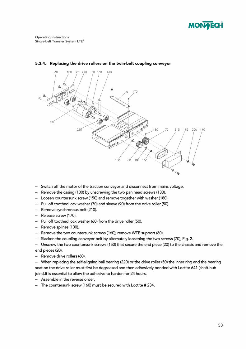
5.3.4. Replacing the drive rollers on the twin-belt coupling conveyor
– Switch off the motor of the traction conveyor and disconnect from mains voltage. – Remove the casing (100) by unscrewing the two pan head screws (130). – Loosen countersunk screw (150) and remove together with washer (180). – Pull off toothed lock washer (70) and sleeve (90) from the drive roller (50). – Remove synchronous belt (210). – Release screw (170). – Pull off toothed lock washer (60) from the drive roller (50). – Remove splines (130). – Remove the two countersunk screws (160); remove WTE support (80). – Slacken the coupling conveyor belt by alternately loosening the two screws (70), Fig. 2. – Unscrew the two countersunk screws (150) that secure the end piece (20) to the chassis and remove the end pieces (20). – Remove drive rollers (60). – When replacing the self-aligning ball bearing (220) or the drive roller (50) the inner ring and the bearing seat on the drive roller must first be degreased and then adhesively bonded with Loctite 641 (shaft-hub joint).It is essential to allow the adhesive to harden for 24 hours. – Assemble in the reverse order. – The countersunk screw (160) must be secured with Loctite # 234.

Operating Instructions Single-belt Transfer System LTE®
54
5.4. Maintenance
Belt conveyors are maintenance free when they are employed in accordance with their purpose and are not exposed to any factors likely to shorten the useful life. The purpose and the factors likely to shorten life are listed in the declaration of conformity. When the belts are exposed to the action of dust, oily air, foreign matter such as metal chips from machine tools, etc., we recommend that they should be regularly cleaned, e.g. once a week, with pure gasoline.
5.5. Repairs
The operating instructions contain the necessary spare parts lists and exploded drawings for repairs to the mechanical part of the conveyor. The safety instructions must also be followed. Repairs to the electrical part may be carried out only by the supplier. It is essential to follow the safety instructions for electrical disconnection of components from the mains or from the motor and for subsequent reinstallation.

Operating Instructions Single-belt Transfer System LTE®
55
5.6. Exploded Views / Spare Parts Lists
5.6.1. Conveyor coupling TB/TB and TB/TBD
5.6.2. Spare parts list conveyor coupling TB/TB and TB/TBD
Item Name Item no.
TB/TBD-105 TB/TBD-140 TB/TBD-185 TB/TBD-250
10 Chassis aluminum with sliding plate
55388/…. 55389/…. 55390/…. 55391/….
Sliding plate sendzimir-galvanized
54869/0084/…. 54869/0119/…. 54869/0164/…. 54869/0229/….
Sliding plate stainless 54868/0084/…. 54868/0119/…. 54868/0164/…. 54868/0229/….
20 Conveyor end to BKE TB/TB with diverter roller, single-belt
55208 55209 55210 55298
20 Conveyor end to BKE TB/TBD with diverter roller, twin-belt
55211 55212 55213 55297
30 Conveyor coupling for TB/TB 55396 55397 55398 56299
30 Conveyor coupling for TB/TBD 55399 55400 55401 56296

Operating Instructions Single-belt Transfer System LTE®
56
5.6.3. BKE conveyor end with diverter roller, single-belt
5.6.4. Spare parts list BKE conveyor end TB/TB with diverter roller, single-belt
Item Sym. Name Item no. Material
TB-105 TB-140 TB-185 TB-250
◘ Conveyor end, complete 55208 55209 55210 56298 Various
10 ◊ Conveyor end 55134 55135 55136 56129 Aluminum
20 ◘ Conveyor-conveyor elem.,
complete 36546
36546 36546 36546 Steel
30 ● Diverter roller, complete 57370 57373 57374 57375 Steel
● These are wearing parts and available ex stock. ◊ Not available ex stock individually (upon request) ◘ Price list item available ex stock
Operating Instructions Single-belt Transfer System LTE®
57
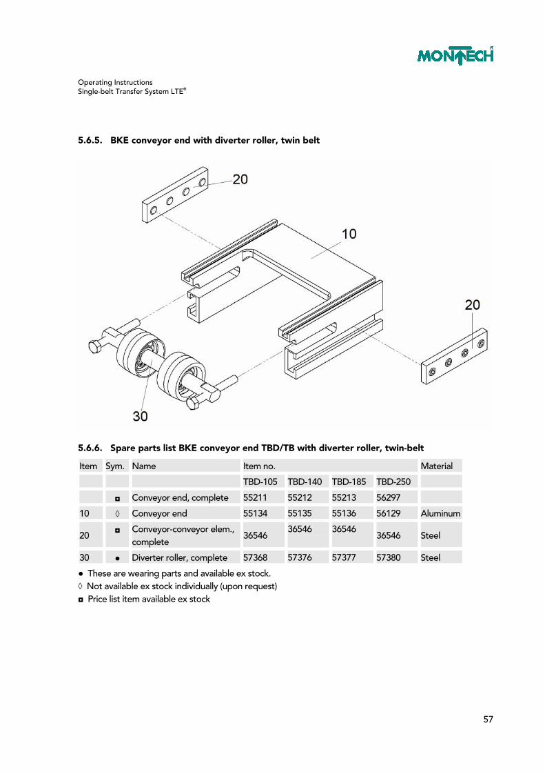
5.6.5. BKE conveyor end with diverter roller, twin belt
5.6.6. Spare parts list BKE conveyor end TBD/TB with diverter roller, twin-belt
Item Sym. Name Item no. Material
TBD-105 TBD-140 TBD-185 TBD-250
◘ Conveyor end, complete 55211 55212 55213 56297
10 ◊ Conveyor end 55134 55135 55136 56129 Aluminum
20 ◘ Conveyor-conveyor elem.,
complete 36546
36546 36546 36546 Steel
30 ● Diverter roller, complete 57368 57376 57377 57380 Steel
● These are wearing parts and available ex stock. ◊ Not available ex stock individually (upon request) ◘ Price list item available ex stock

Operating Instructions Single-belt Transfer System LTE®
58
5.6.7. Conveyor coupling for TB/TB

Operating Instructions Single-belt Transfer System LTE®
59
5.6.8. Spare parts list conveyor coupling for TB/TB with diverter roller, single-belt
Item Sym. Name Item no. Material
TB-105 TB-140 TB-185 TB-250
◘ Conveyor coupling,
complete 55396 55397 55398 56299 Various
10 ◊ End piece right for BKE 55190 55190 55190 55190 Various
20 ◊ End piece left for BKE 55191 55191 55191 55191 Various
30 ◊ End piece left for TB 55188 55188 55188 55188 Various
40 ◊ End piece right for TB 55189 55189 55189 55189 Various
50 ● Drive roller for BKE 55125 55126 55127 56127 Steel
60 ● Toothed lock washer
5MR-21S 55137 55137 55137 55137 Aluminum
70 ● Toothed lock washer
5MR-21S 55138 55138 55138 55138 Aluminum
80 ◊ WT support 55118 55119 55120 56128 Steel
90 ◊ Sleeve 55140 55140 55140 55140 Steel
100 ◊ Casing 55139 55139 55139 55139 Steel
110 ● Synchronous belt
5MR-200-15 508454 508454 508454 508454 Plastics
120 ◊ Machine elements 55330 55330 55330 55330 Steel
120/130 ◊ Spline 3x3x18 508453 508453 508453 508453 Steel
120/140 ◊ Countersunk screw M5x10 504901 504901 504901 504901 Steel
120/150 ◊ Countersunk screw M4x8 505322 505322 505322 505322 Steel
120/160 ◊ Setscrew M3x6 501886 501886 501886 501886 Steel
120/170 ◊ Setscrew washer M5 504381 504381 504381 504381 Steel
● These are wearing parts and available ex stock. ◊ Not available ex stock individually (upon request) ◘ Price list item available ex stock

Operating Instructions Single-belt Transfer System LTE®
60
5.6.9. Conveyor coupling for TBD/TB
Operating Instructions Single-belt Transfer System LTE®
61
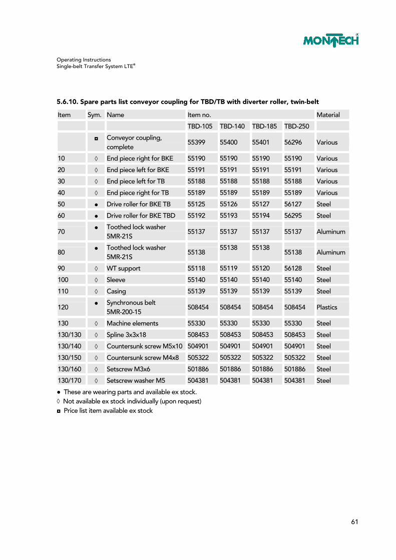
5.6.10. Spare parts list conveyor coupling for TBD/TB with diverter roller, twin-belt
Item Sym. Name Item no. Material
TBD-105 TBD-140 TBD-185 TBD-250
◘ Conveyor coupling,
complete 55399 55400 55401 56296 Various
10 ◊ End piece right for BKE 55190 55190 55190 55190 Various
20 ◊ End piece left for BKE 55191 55191 55191 55191 Various
30 ◊ End piece left for TB 55188 55188 55188 55188 Various
40 ◊ End piece right for TB 55189 55189 55189 55189 Various
50 ● Drive roller for BKE TB 55125 55126 55127 56127 Steel
60 ● Drive roller for BKE TBD 55192 55193 55194 56295 Steel
70 ● Toothed lock washer
5MR-21S 55137 55137 55137 55137 Aluminum
80 ● Toothed lock washer
5MR-21S 55138
55138 55138 55138 Aluminum
90 ◊ WT support 55118 55119 55120 56128 Steel
100 ◊ Sleeve 55140 55140 55140 55140 Steel
110 ◊ Casing 55139 55139 55139 55139 Steel
120 ● Synchronous belt
5MR-200-15 508454 508454 508454 508454 Plastics
130 ◊ Machine elements 55330 55330 55330 55330 Steel
130/130 ◊ Spline 3x3x18 508453 508453 508453 508453 Steel
130/140 ◊ Countersunk screw M5x10 504901 504901 504901 504901 Steel
130/150 ◊ Countersunk screw M4x8 505322 505322 505322 505322 Steel
130/160 ◊ Setscrew M3x6 501886 501886 501886 501886 Steel
130/170 ◊ Setscrew washer M5 504381 504381 504381 504381 Steel
● These are wearing parts and available ex stock. ◊ Not available ex stock individually (upon request) ◘ Price list item available ex stock
Operating Instructions Single-belt Transfer System LTE®
62
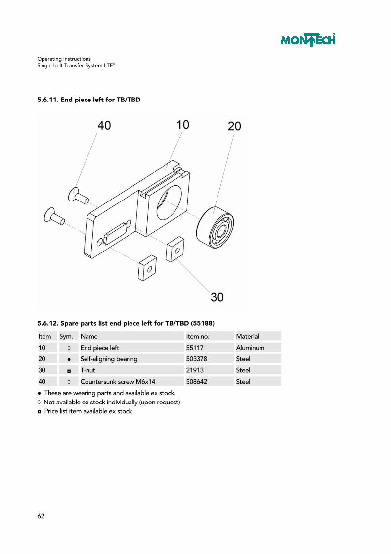
5.6.11. End piece left for TB/TBD
5.6.12. Spare parts list end piece left for TB/TBD (55188)
Item Sym. Name Item no. Material
10 ◊ End piece left 55117 Aluminum
20 ● Self-aligning bearing 503378 Steel
30 ◘ T-nut 21913 Steel
40 ◊ Countersunk screw M6x14 508642 Steel
● These are wearing parts and available ex stock. ◊ Not available ex stock individually (upon request) ◘ Price list item available ex stock

Operating Instructions Single-belt Transfer System LTE®
63
5.6.13. End piece right for TB/TBD
5.6.14. Spare parts list end piece right for TB/TBD (55189)
Item Sym. Name Item no. Material
10 ◊ End piece right 55114 Aluminum
20 ● Self-aligning bearing 503378 Steel
30 ◘ T-nut 21913 Steel
40 ◊ Countersunk screw M6x14 508642 Steel
50 ◊ Cheese head screws M6x16 505486 Steel
60 ◊ Ribbed washer M6 Steel
● These are wearing parts and available ex stock. ◊ Not available ex stock individually (upon request) ◘ Price list item available ex stock

Operating Instructions Single-belt Transfer System LTE®
64
5.6.15. End piece right for BKE
5.6.16. Spare parts list end piece right for BKE (55190)
Item Sym. Name Item no. Material
10 ◊ End piece right 55115 Aluminum
20 ● Self-aligning bearing 503378 Steel
30 ◊ Cheese head pin ø5x10 502047 Steel
40 ◘ T-nut 21913 Steel
50 ◊ Countersunk screw M6x14 508642 Steel
60 ◊ Cheese head screws M6x16 505486 Steel
70 ◊ Ribbed washer M6 505255 Steel
● These are wearing parts and available ex stock. ◊ Not available ex stock individually (upon request) ◘ Price list item available ex stock

Operating Instructions Single-belt Transfer System LTE®
65
5.6.17. End piece left for BKE
5.6.18. Spare parts list end piece left for BKE (55191)
Item Sym. Name Item no. Material
10 ◊ End piece left 55116 Aluminum
20 ● Self-aligning bearing 503378 Steel
30 ◊ Cylindrical pin ø5x10 502047 Steel
40 ◘ T-nut 21913 Steel
50 ◊ Countersunk screw M6x14 508642 Steel
● These are wearing parts and available ex stock. ◊ Not available ex stock individually (upon request) ◘ Price list item available ex stock

Operating Instructions Single-belt Transfer System LTE®
66
6. Fixed Curve 90° KFE
6.1. Use
To divert a workpiece holder WTE by 90° at the belt end (version E) or in any other place of the conveyor (version M).
6.2. Commissioning
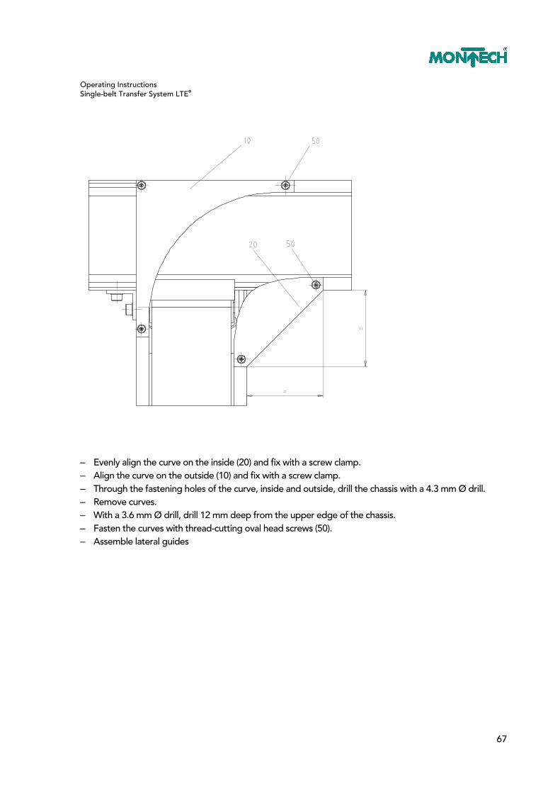
6.2.1. Curve fixed 90° KFE 105, 140, 185 and 250, version M
– Specify position of the conveyor, dimension X. – Mount fastening bracket (40). – Center and snap on finger protection device (30).
Operating Instructions Single-belt Transfer System LTE®
67
– Evenly align the curve on the inside (20) and fix with a screw clamp. – Align the curve on the outside (10) and fix with a screw clamp. – Through the fastening holes of the curve, inside and outside, drill the chassis with a 4.3 mm Ø drill. – Remove curves. – With a 3.6 mm Ø drill, drill 12 mm deep from the upper edge of the chassis. – Fasten the curves with thread-cutting oval head screws (50). – Assemble lateral guides

Operating Instructions Single-belt Transfer System LTE®
68
6.2.2. Curve fixed 90° KFE 105, 140, 185 and 250, version E
– Insert special T-nut (10) into the T-slot of the chassis so it is flush. – Screw in and tighten setscrew (90). – Connect the two chassis with the chassis binder (20). – For reinforcement, screw on brackets (40).

Operating Instructions Single-belt Transfer System LTE®
69
– Center and snap on finger protection device (30) – Evenly (=) align the inside curve (20) and fix with a screw clamp. – Align the curve on the outside (10) and fix with a screw clamp. – Through the fastening holes of the curve, inside and outside, drill the chassis with a 4.3 mm Ø drill. – Remove curves. – With a 3.6 mm Ø drill, drill 12 mm deep from the upper edge of the chassis. – Fasten the curves with thread-cutting oval head screws (50). – Assemble lateral guides

Operating Instructions Single-belt Transfer System LTE®
70
6.3. Exploded Views / Spare Parts Lists
6.3.1. Fixed curve 90° KFE 105, 140, 185, and 250, version M
6.3.2. Spare parts list fixed curve KFE, version M
Item Sym. Name Item no. Material
TB-105 TB-140 TB-185 TB-250
◘ Fixed curve 49634 49633 49632 56313 Various
10 ● Curve, outside 49479 49486 49489 56013 PE
20 ● Curve, inside 49485 49488 49490 56012 PE
30 ● Finger protection device 49641 49642 49643 56314 PE
40 ◊ Connection 90° (pair) 49628 49628 49628 49628 Steel
50 ◊ Thread-forming
oval head screw M4x20 508972 508972 508972 508972 Steel
● These are wearing parts and available ex stock. ◊ Not available ex stock individually (upon request) ◘ Price list item available ex stock

Operating Instructions Single-belt Transfer System LTE®
71
6.3.3. Fixed curve 90° KFE 105, 140, 185, and 250, version E
6.3.4. Spare parts list fixed curve KFE, version E
Item Sym. Name Item no. Material
TB-105 TB-140 TB-185 TB-250
◘ Fixed curve 49617 49618 49619 56312 Various
10 ● Curve, outside 49479 49486 49489 56013 PE
20 ● Curve, inside 49485 49488 49490 56012 PE
30 ● Finger protection device 49641 49642 49643 56314 PE
40 ◊ Connection 90° 49393 49394 49395 56311 Steel
50 ◊ Thread-forming
oval head screw M4x20 508972 508972 508972 508972 Steel
● These are wearing parts and available ex stock. ◊ Not available ex stock individually (upon request) ◘ Price list item available ex stock

Operating Instructions Single-belt Transfer System LTE®
72
6.3.5. Connection 90° for KFE, version M
6.3.6. Spare parts list connection 90° for KFE, version M (49628)
Item Sym. Name Item no. Material
10 ◘ T-nut 21913 Steel
20 ◊ Fastening bracket 54547 Steel
30 ◊ Cheese head screw M6x12 504644 PE
40 ◊ Ribbed washer M6 505255 Steel
◊ Not available ex stock individually (upon request) ◘ Price list item available ex stock

Operating Instructions Single-belt Transfer System LTE®
73
6.3.7. Connection 90° for KFE, version E
6.3.8. Spare parts list connection 90° for KFE, version E
Item Sym. Name TB-105 TB-140 TB-185 TB-250 Material
◘ Item no. 49393 49394 49395 56311
10 ◊ Special T-nut 49322 49322 49322 49322 Steel
20 ◊ Connection plate 90° 49323 49324 49325 56310 Steel
30 ◘ T-nut 21913 21913 21913 21913 Steel
40 ◊ Fastening bracket 54547 54547 54547 54547 Steel
50 ◊ Cheese head screw M5x10 506396 506396 506396 506396 Steel
60 ◊ Ribbed washer M5 505254 505254 505254 505254 Steel
70 ◊ Cheese head screw M6x12 504644 504644 504644 504644 Steel
80 ◊ Ribbed washer M6 505255 505255 505255 505255 Steel
90 ◊ Setscrew M6x8 505116 505116 505116 505116 Steel
● These are wearing parts and available ex stock. ◊ Not available ex stock individually (upon request) ◘ Price list item available ex stock
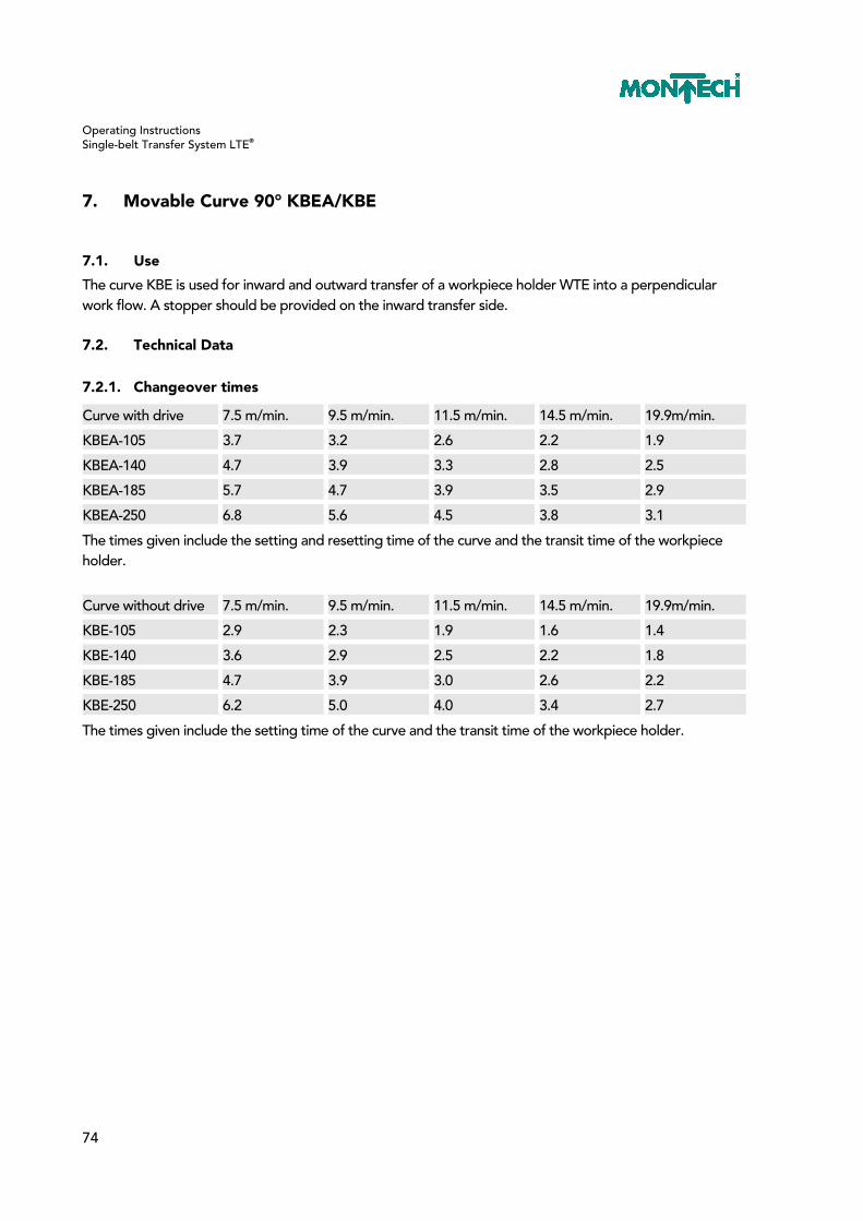
Operating Instructions Single-belt Transfer System LTE®
74
7. Movable Curve 90° KBEA/KBE
7.1. Use
The curve KBE is used for inward and outward transfer of a workpiece holder WTE into a perpendicular work flow. A stopper should be provided on the inward transfer side.
7.2. Technical Data
7.2.1. Changeover times
Curve with drive 7.5 m/min. 9.5 m/min. 11.5 m/min. 14.5 m/min. 19.9m/min.
KBEA-105 3.7 3.2 2.6 2.2 1.9
KBEA-140 4.7 3.9 3.3 2.8 2.5
KBEA-185 5.7 4.7 3.9 3.5 2.9
KBEA-250 6.8 5.6 4.5 3.8 3.1
The times given include the setting and resetting time of the curve and the transit time of the workpiece holder.
Curve without drive 7.5 m/min. 9.5 m/min. 11.5 m/min. 14.5 m/min. 19.9m/min.
KBE-105 2.9 2.3 1.9 1.6 1.4
KBE-140 3.6 2.9 2.5 2.2 1.8
KBE-185 4.7 3.9 3.0 2.6 2.2
KBE-250 6.2 5.0 4.0 3.4 2.7
The times given include the setting time of the curve and the transit time of the workpiece holder.
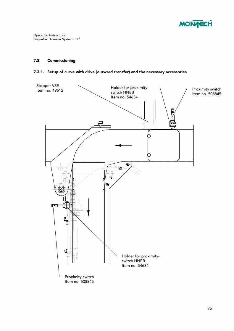
Operating Instructions Single-belt Transfer System LTE®
75
7.3. Commissioning
7.3.1. Setup of curve with drive (outward transfer) and the necessary accessories
Proximity switch Item no. 508845
Stopper VSE Item no. 49612
Holder for proximity-switch HNEB Item no. 54634
Holder for proximity-switch HNEB Item no. 54634
Proximity switch Item no. 508845

Operating Instructions Single-belt Transfer System LTE®
76
7.3.2. Setup of curve without drive (inward transfer) and the necessary accessories
Stopper VSE Item no. 49612
Holder for proximity-switch HNEB Item no. 54634
Proximity switch Item no. 508845
Holder for proximity-switch HNEB Item no. 54634
Proximity switch Item no. 508845
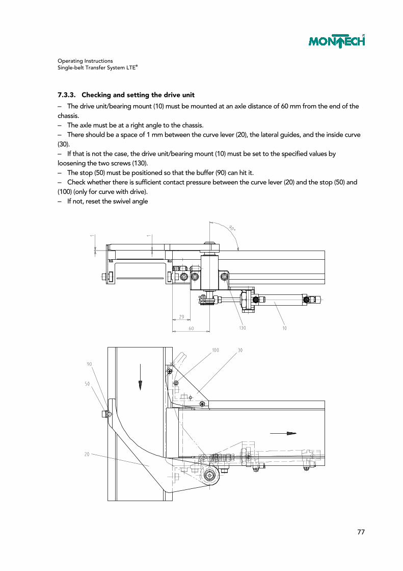
Operating Instructions Single-belt Transfer System LTE®
77
7.3.3. Checking and setting the drive unit
– The drive unit/bearing mount (10) must be mounted at an axle distance of 60 mm from the end of the chassis. – The axle must be at a right angle to the chassis. – There should be a space of 1 mm between the curve lever (20), the lateral guides, and the inside curve (30). – If that is not the case, the drive unit/bearing mount (10) must be set to the specified values by loosening the two screws (130). – The stop (50) must be positioned so that the buffer (90) can hit it. – Check whether there is sufficient contact pressure between the curve lever (20) and the stop (50) and (100) (only for curve with drive). – If not, reset the swivel angle

Operating Instructions Single-belt Transfer System LTE®
78
7.3.4. Checking and setting the bearings

Operating Instructions Single-belt Transfer System LTE®
79
7.3.5. Flowchart for curve with drive (outward transfer)
straight
Z1 Cylinder, double-acting Stopper
Z2 Cylinder, double-acting Drive unit
N1 Proximity switch Presence
N2 Proximity switch Presence/ queue monitoring
N3 Proximity switch Drive unit cylinder OFF
N4 Proximity switch Drive unit cylinder ON
N5 Proximity switch Stopper cylinder ON
N6 Proximity switch Stopper cylinder OFF
N7 Proximity switch Presence/ queue monitoring
queuing
outw
ard

Operating Instructions Single-belt Transfer System LTE®
80
Start
Z1 OFF
N6 assigned
Z2 OFF
noyes
N3 assigned
N2 unassigned
N7 unassigned
outwardtransfer
N1 assigned
no
noyes
yes
outwardtransfer
T expired
N5 assigned
N2 unassigned
Z1 OFF
T delay time
Z1 ON
N6 assignedno
no
no
no
no
yes
yes
yes
yes
yes
yes
yes
no
N1 assigned
T expired
N5 assigned
N7 unassigned
Z1 OFF
T delay time
Z1 ON
N6 assignedno
no
no
no
no
yes
yes
yes
yes
yes
yes
N4 assigned
Z2 ON
no
yesstraight
yes
no
no
noyes
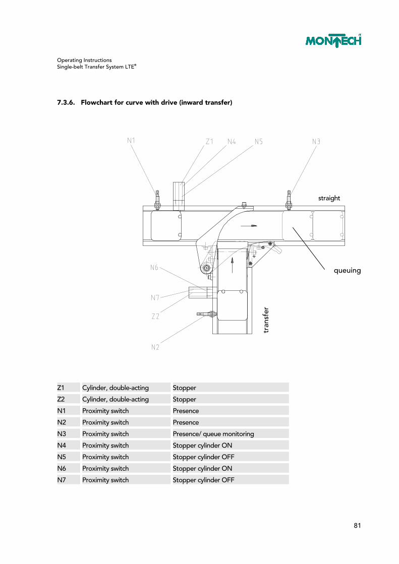
Operating Instructions Single-belt Transfer System LTE®
81
7.3.6. Flowchart for curve with drive (inward transfer)
straight
Z1 Cylinder, double-acting Stopper
Z2 Cylinder, double-acting Stopper
N1 Proximity switch Presence
N2 Proximity switch Presence
N3 Proximity switch Presence/ queue monitoring
N4 Proximity switch Stopper cylinder ON
N5 Proximity switch Stopper cylinder OFF
N6 Proximity switch Stopper cylinder ON
N7 Proximity switch Stopper cylinder OFF
tran
sfer
queuing
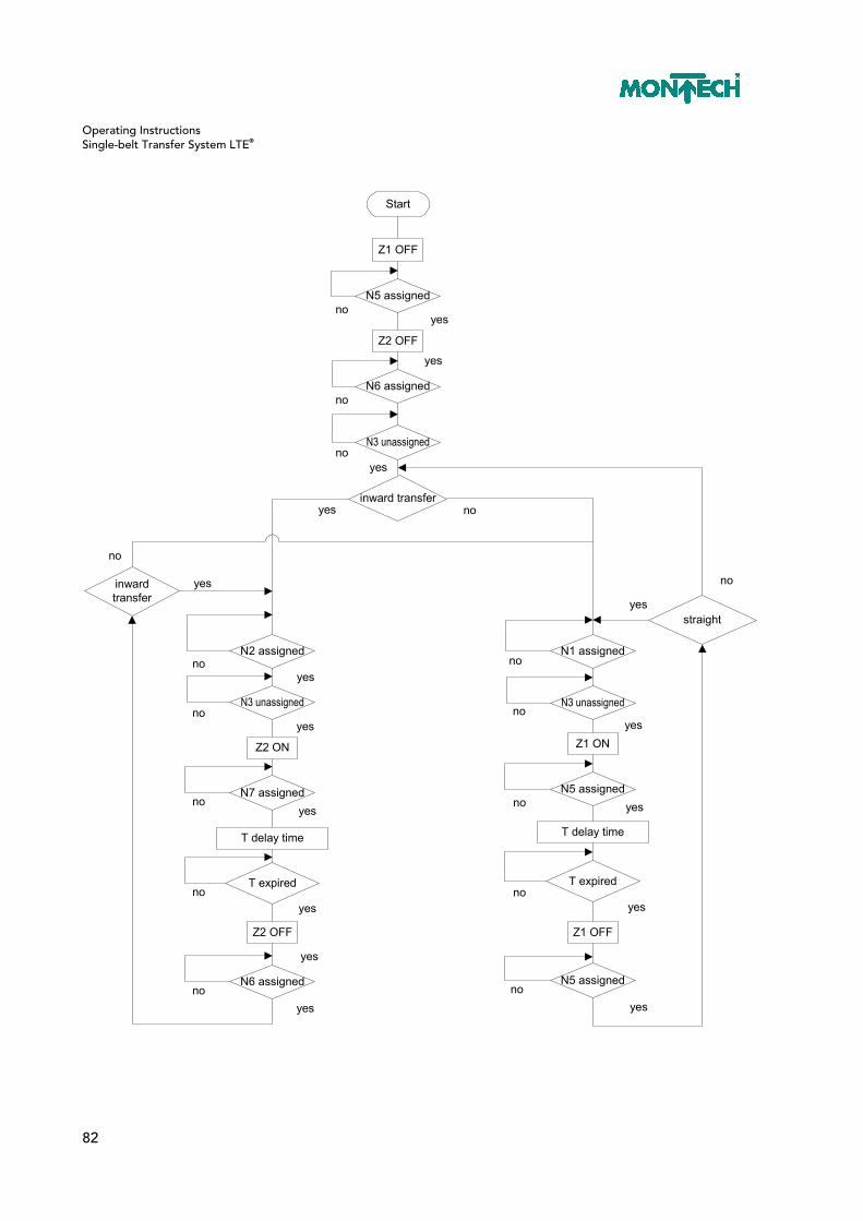
Operating Instructions Single-belt Transfer System LTE®
82
Start
Z1 OFF
N5 assigned
Z2 OFF
noyes
N6 assigned
N3 unassigned
inward transfer
N2 assigned
no
no
yes
yes
inwardtransfer
T expired
N7 assigned
N3 unassigned
Z2 OFF
T delay time
Z2 ON
N6 assignedno
no
no
no
no
yes
yes
yes
yes
yes
yes
yes
no
N3 unassigned
T expired
N5 assigned
Z1 OFF
T delay time
Z1 ON
N5 assignedno
no
no
no
yes
yes
yes
yes
N1 assignedno
yesstraight
yes no
no

Operating Instructions Single-belt Transfer System LTE®
83
7.4. Maintenance and Repairs
7.4.1. Replacing the drive cylinder
– Turn off system. – Bleed compressed air system. – Remove drive by loosening the two screws (130) (see next page). – Remove the two pneumatic hoses from the exhaust air valve (90). – Release clip (70/2) and pull down out of the fork end (70/1). – Remove the two setscrews with shank (110). – Remove cylinder (80/1). – Remove the fork end (70/1) and the hex nuts (80/2) and (80/3), disassemble ring (30) from the defective cylinder and mount on the new cylinder. Care must be taken to screw the fork end back to its original size. – Assemble in the reverse order – Check swivel angles and reset, if necessary

Operating Instructions Single-belt Transfer System LTE®
84
7.4.2. Replacing the drive unit
– Turn off system. – Bleed compressed air system. – Loosen countersunk screw (140) and washer (170) and remove. – Pull curve lever (20) up and out. – Remove pad (40). – Remove the two screws (130) and remove. – Replace drive unit (10). – Assemble in the reverse order. – Check swivel angles and reset, if necessary.

Operating Instructions Single-belt Transfer System LTE®
85
7.4.3. Checking and setting the swivel angle
– Extend cylinder. – The curve lever (20) must be on position 1. – Check if the curve lever applies noticeable pressure to the stop (50). – If yes, continue with point 16; if not, continue with point 5. – Turn off system. – Bleed compressed air system. – Release clip (70/2) and pull down out of the fork end (70/1). – Swivel cylinder (80/1) out. – Loosen hex nut (80/3). – Loosen fork end approx. ½ turn – Tighten hex nut (80/3). – Swivel cylinder (80/1) in. – Mount clip (70/2). – Turn on system. – Perform steps 1 to 3. – Retract cylinder. – The curve lever (20) must be on position 2. – Check if the curve lever applies noticeable pressure to the stop (100). – If not, the procedure is the same as starting with point 6; except in point 10, the fork end must be screwed in ½ turn.

Operating Instructions Single-belt Transfer System LTE®
86

Operating Instructions Single-belt Transfer System LTE®
87
7.5. Exploded Views / Spare Parts Lists
7.5.1. Movable curve with drive
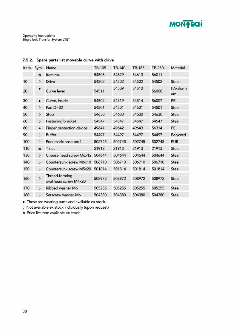
Operating Instructions Single-belt Transfer System LTE®
88
7.5.2. Spare parts list movable curve with drive
Item Sym. Name TB-105 TB-140 TB-185 TB-250 Material
◘ Item no. 54506 54629 54613 56011
10 ◊ Drive 54502 54502 54502 54502 Steel
20 ●
Curve lever 54511 54509 54510
56008 PA/aluminum
30 ● Curve, inside 54504 54519 54514 56007 PE
40 ◊ Pad D=32 54501 54501 54501 54501 Steel
50 ◊ Stop 54630 54630 54630 54630 Steel
60 ◊ Fastening bracket 54547 54547 54547 54547 Steel
80 ● Finger protection device 49641 49642 49643 56314 PE
90 ◊ Buffer 54497 54497 54497 54497 Polycord
100 ◊ Pneumatic hose ø6/4 502745 502745 502745 502745 PUR
110 ◘ T-nut 21913 21913 21913 21913 Steel
130 ◊ Cheese head screw M6x12 504644 504644 504644 504644 Steel
140 ◊ Countersunk screw M6x10 506710 506710 506710 506710 Steel
150 ◊ Countersunk screw M5x20 501814 501814 501814 501814 Steel
160 ◊ Thread-forming oval head screw M4x20
508972 508972 508972 508972 Steel
170 ◊ Ribbed washer M6 505255 505255 505255 505255 Steel
180 ◊ Setscrew washer M6 504380 504380 504380 504380 Steel
● These are wearing parts and available ex stock. ◊ Not available ex stock individually (upon request) ◘ Price list item available ex stock

Operating Instructions Single-belt Transfer System LTE®
89
7.5.3. Movable curve without drive

Operating Instructions Single-belt Transfer System LTE®
90
7.5.4. Spare parts list movable curve without drive
Item Sym. Name TB-105 TB-140 TB-185 TB-250 Material
◘ Item no. 54610 54612 54614 56375
10 ◊ Bearing 54531 54531 54531 54531 Steel
20 ●
Curve lever 54511 54509 54510
56008 PA/aluminum
30 ● Curve, inside 54504 54519 54514 56007 PE
40 ◊ Pad D=32 54501 54501 54501 54501 Steel
50 ◊ Stop 54630 54630 54630 54630 Steel
60 ◊ Fastening bracket 54549 54549 54549 54549 Steel
70 ◊ Fastening bracket left 54548 54548 54548 54548 Steel
80 ● Finger protection device 49641 49642 49643 56314 PE
90 ◊ Buffer 54497 54497 54497 54497 Polycord
100 ◊ Pneumatic hose ø6/4 502745 502745 502745 502745 PUR
110 ◘ T-nut 21913 21913 21913 21913 Steel
130 ◊ Cheese head screw M6x12 504644 504644 504644 504644 Steel
140 ◊ Countersunk screw M6x10 506710 506710 506710 506710 Steel
150 ◊ Countersunk screw M5x20 501814 501814 501814 501814 Steel
160 ◊ Thread-forming oval head screw M4x20
508972 508972 508972 508972 Steel
170 ◊ Ribbed washer M6 505255 505255 505255 505255 Steel
180 ◊ Setscrew washer M6 504380 504380 504380 504380 Steel
● These are wearing parts and available ex stock. ◊ Not available ex stock individually (upon request) ◘ Price list item available ex stock

Operating Instructions Single-belt Transfer System LTE®
91
7.5.5. Drive for curve

Operating Instructions Single-belt Transfer System LTE®
92
7.5.6. Spare parts list drive for curve (54502)
Item Sym. Name Item no. Material
10 ◊ Console for drive 56374 Steel
20 ◊ Shaft for drive 56372 Steel
30 ◊ Ring for drive 54500 Steel
40 ◊ Lever 54488 Steel
50 ● Deep groove ball bearing 520036 Steel
60 ◊ Sliding bearing with collar 508361 Steel
70 ● Fork end SG-M6 503616 Steel
80 ● ISO cylinder CD85N16-40B SMC 508373 Steel
90 ◊ Ex air valve fitting M5 505023 Steel
100 ◊ Countersunk screws M5x10 504901 Steel
110 ◊ Setscrew with shank M5x12 508375 Steel
130 ◊ Setscrew washer M5 504381 Steel
140 ◊ Retaining ring ø10 502448 Steel
150 ◊ Warning sign 54792 Steel
● These are wearing parts and available ex stock. ◊ Not available ex stock individually (upon request)
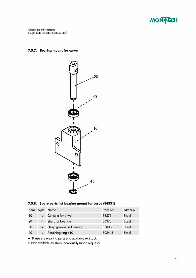
Operating Instructions Single-belt Transfer System LTE®
93
7.5.7. Bearing mount for curve
7.5.8. Spare parts list bearing mount for curve (54531)
Item Sym. Name Item no. Material
10 ◊ Console for drive 56371 Steel
20 ◊ Shaft for bearing 56373 Steel
30 ● Deep groove ball bearing 520036 Steel
40 ◊ Retaining ring ø10 502448 Steel
● These are wearing parts and available ex stock. ◊ Not available ex stock individually (upon request)

Operating Instructions Single-belt Transfer System LTE®
94
7.5.9. Stop for movable curve and bypass
7.5.10. Spare parts list stop for movable curve and bypass (54630)
Item Sym. Name Item no. Material
10 ◊ Stop 54631 Steel
20 ◘ T-nut 21913 Steel
30 ◊ Cheese head screw M6x12 504644 Steel
40 ◊ Lock washer M6 504744 Steel
◊ Not available ex stock individually (upon request) ◘ Price list item available ex stock
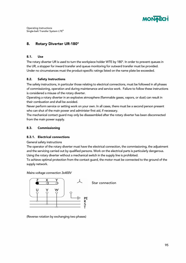
Operating Instructions Single-belt Transfer System LTE®
95
8. Rotary Diverter UR-180°
8.1. Use
The rotary diverter UR is used to turn the workpiece holder WTE by 180°. In order to prevent queues in the UR, a stopper for inward transfer and queue monitoring for outward transfer must be provided. Under no circumstances must the product-specific ratings listed on the name plate be exceeded.
8.2. Safety Instructions
The safety instructions, in particular those relating to electrical connections, must be followed in all phases of commissioning, operation and during maintenance and service work. Failure to follow these instructions is considered a misuse of the rotary diverter. Operating a rotary diverter in an explosive atmosphere (flammable gases, vapors, or dust) can result in their combustion and shall be avoided. Never perform service or setting work on your own. In all cases, there must be a second person present who can shut of the main power and administer first aid, if necessary. The mechanical contact guard may only be disassembled after the rotary diverter has been disconnected from the main power supply.
8.3. Commissioning
8.3.1. Electrical connections
General safety instructions The operator of the rotary diverter must have the electrical connection, the commissioning, the adjustment and the servicing carried out by qualified persons. Work on the electrical parts is particularly dangerous. Using the rotary diverter without a mechanical switch in the supply line is prohibited. To achieve optimal protection from the contact guard, the motor must be connected to the ground of the supply network. Mains voltage connection 3x400V (Reverse rotation by exchanging two phases)
Star connection
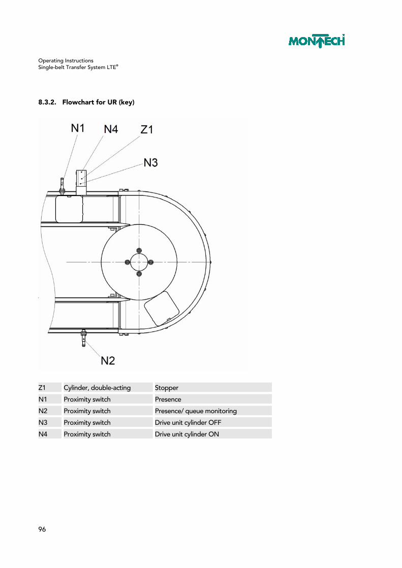
Operating Instructions Single-belt Transfer System LTE®
96
8.3.2. Flowchart for UR (key)
Z1 Cylinder, double-acting Stopper
N1 Proximity switch Presence
N2 Proximity switch Presence/ queue monitoring
N3 Proximity switch Drive unit cylinder OFF
N4 Proximity switch Drive unit cylinder ON

Operating Instructions Single-belt Transfer System LTE®
97
Start
Z1 OFF
N3 occupiedno
yes
N1 occupied
N4 occupiedno
no
yes
no
yes
N3 occupied
yes
N2 free
Delay timeT1 for Z1
=0
yes
Z1 ON
END OFPROGR.
yes
no
Z1 OFF
END
yes
no
no
yes
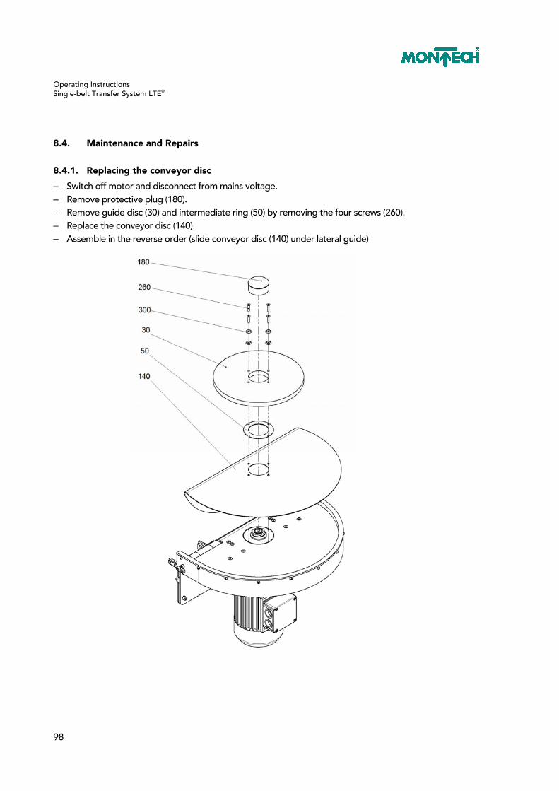
Operating Instructions Single-belt Transfer System LTE®
98
8.4. Maintenance and Repairs
8.4.1. Replacing the conveyor disc
– Switch off motor and disconnect from mains voltage. – Remove protective plug (180). – Remove guide disc (30) and intermediate ring (50) by removing the four screws (260). – Replace the conveyor disc (140). – Assemble in the reverse order (slide conveyor disc (140) under lateral guide)
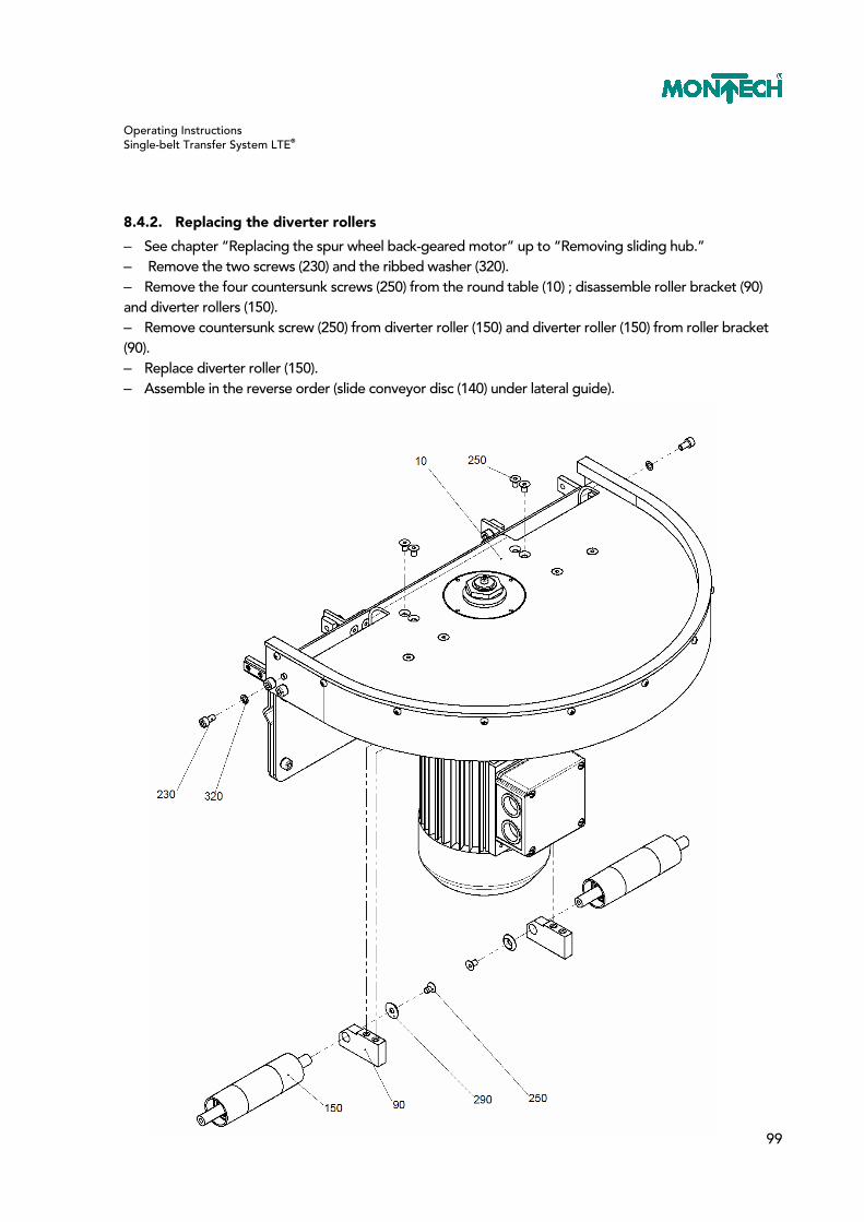
Operating Instructions Single-belt Transfer System LTE®
99
8.4.2. Replacing the diverter rollers
– See chapter “Replacing the spur wheel back-geared motor” up to “Removing sliding hub.” – Remove the two screws (230) and the ribbed washer (320). – Remove the four countersunk screws (250) from the round table (10) ; disassemble roller bracket (90) and diverter rollers (150). – Remove countersunk screw (250) from diverter roller (150) and diverter roller (150) from roller bracket (90). – Replace diverter roller (150). – Assemble in the reverse order (slide conveyor disc (140) under lateral guide).
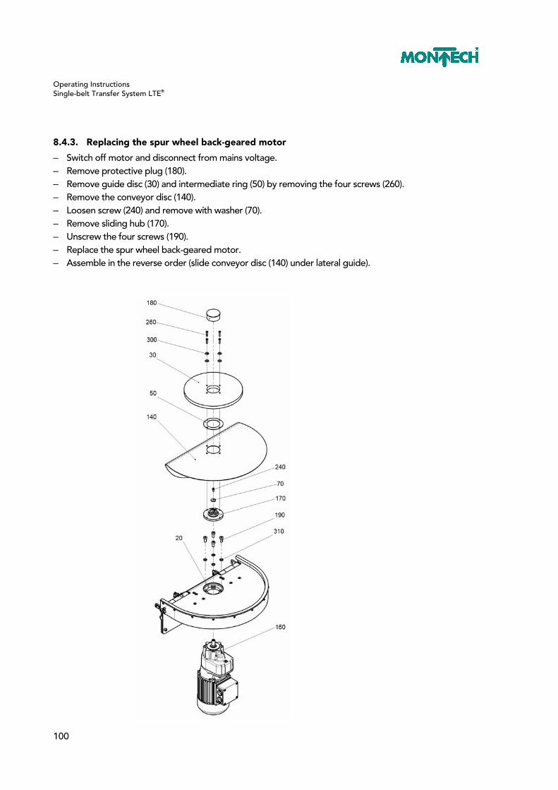
Operating Instructions Single-belt Transfer System LTE®
100
8.4.3. Replacing the spur wheel back-geared motor
– Switch off motor and disconnect from mains voltage. – Remove protective plug (180). – Remove guide disc (30) and intermediate ring (50) by removing the four screws (260). – Remove the conveyor disc (140). – Loosen screw (240) and remove with washer (70). – Remove sliding hub (170). – Unscrew the four screws (190). – Replace the spur wheel back-geared motor. – Assemble in the reverse order (slide conveyor disc (140) under lateral guide).

Operating Instructions Single-belt Transfer System LTE®
101
8.4.4. Replacing the sliding hub
– See chapter “Replacing the spur wheel back-geared motor” up to “Removing sliding hub.” – Replace the sliding hub. – Assemble in the reverse order (slide conveyor disc (140) under lateral guide).
8.4.5. Adjusting the sliding hub
– See chapter “Replacing the spur wheel back-geared motor” up to “Removing sliding hub.” – Check the idle torque. If lever L=500 mm, the leverage force is
UR-1 UR-2 UR-3 UR-4
8-10N 9-11N 10-12N 13-16N
– Set test torque: Loosen guard panel; tighten nut until a lever force of L=500mm is measured at the lever (see table below). When measuring, lock the ventilator wheel of the motor.
UR-1 UR-2 UR-3 UR-4
29N 32N 36N 49N
– Once the test torque has been set, secure the nut with the guard panel. – Assemble in the reverse order.
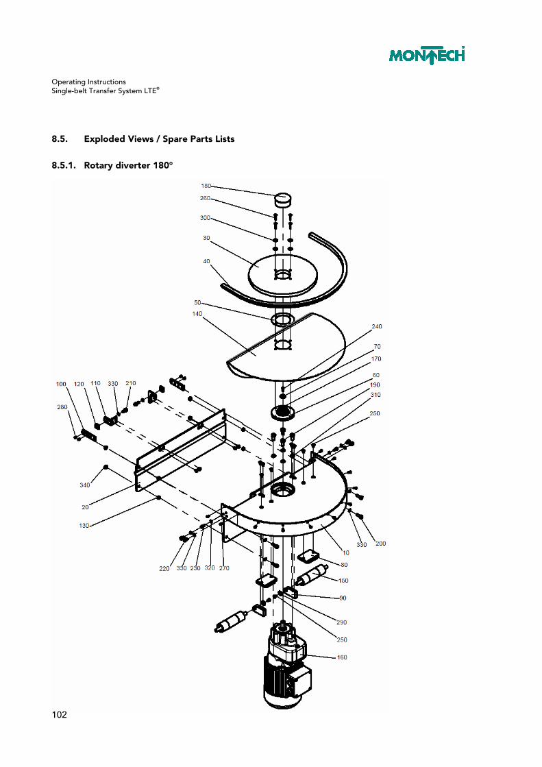
Operating Instructions Single-belt Transfer System LTE®
102
8.5. Exploded Views / Spare Parts Lists
8.5.1. Rotary diverter 180°

Operating Instructions Single-belt Transfer System LTE®
103
8.5.2. Spare parts list rotary diverter 90°
Item Sym. Name TB-105 TB-140 TB-185 TB-250 Material
◘ Item no. 56214 56280 56281 56282
10 ◊ Round table 56204 56230 56232 56243 Steel
20 ◊ Guide panel 56206 56219 56220 56221 Steel
30 ◊ Guide disc 56197 56236 56237 56238 PE
40 ● Lateral guide 56338 56340 56339 56227 PE
50 ◊ Intermediate ring 56198 56198 56198 56198 Steel
60 ◊ Friction plate 56201 56201 56201 56201 Steel
70 ◊ Washer 56196 56196 56196 56196 Steel
80 ◊ Adapter 56199 56199 56199 56199 Aluminum
90 ◊ Roller bracket 56211 56211 56211 56211 Steel
100 ◊ Connection tab 40496 40496 40496 40496 Steel
110 ◊ Angle 56200 56200 56200 56200 Steel
120 ◘ T-nut 21913 21913 21913 21913 Steel
130 ◊ Spacer 40598 40598 40598 40598 Steel
140 ● Conveyor disc 42885 42886 42832 56228 TT-04/XVT-2286
150 ● Diverter roller, complete 38349 38349 38350 38351 Steel
160 ● Gear motor G80F 510002 510002 510002 510002 Various
170 ● Sliding hub RT40.2 508808 508808 508808 508808 Steel
180 ◊ Protective plug TL-4-500 504705 504705 504705 504705 PE
190 ◊ Cheese head screws
M8x16 501781 501781 501781 501781 Steel
200 ◊ Cheese head screws
M6x18 504383 504383 504383 504383 Steel
210 ◊ Cheese head screws
M6x12 504644 504644 504644 504644 Steel
220 ◊ Cheese head screws M6x8 505183 505183 505183 505183 Steel
230 ◊ Cheese head screws
M5x10 506181 506181 506181 506181 Steel
240 ◊ Cheese head screws
M4x16 505328 505328 505328 505328 Steel
250 ◊ Countersunk screw M5x8 504340 504340 504340 504340 Steel
260 ◊ Countersunk screw M4x25 501803 501803 501803 501803 Steel
270 ◊ PT screw 503531 503531 503531 503531 Steel
280 ◊ Setscrew M6x6 504377 504377 504377 504377 Steel

Operating Instructions Single-belt Transfer System LTE®
104
290 ◊ Setscrew washer M5 504381 504381 504381 504381 Steel
300 ◊ Setscrew washer M4 502438 502438 502438 502438 Steel
310 ◊ Ribbed washer M8 502367 502367 502367 502367 Steel
320 ◊ Ribbed washer M5 505254 505254 505254 505254 Steel
330 ◊ Ribbed washer M6 505255 505255 505255 505255 Steel
340 ◊ Hex nut M6x0.8d 504757 504757 504757 504757 Steel
● These are wearing parts and available ex stock. ◊ Not available ex stock individually (upon request) ◘ Price list item available ex stock
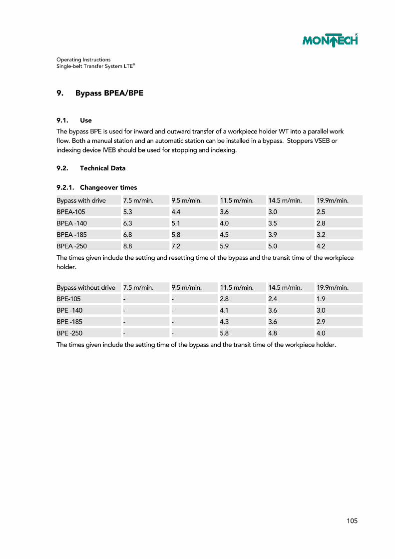
Operating Instructions Single-belt Transfer System LTE®
105
9. Bypass BPEA/BPE
9.1. Use
The bypass BPE is used for inward and outward transfer of a workpiece holder WT into a parallel work flow. Both a manual station and an automatic station can be installed in a bypass. Stoppers VSEB or indexing device IVEB should be used for stopping and indexing.
9.2. Technical Data
9.2.1. Changeover times
Bypass with drive 7.5 m/min. 9.5 m/min. 11.5 m/min. 14.5 m/min. 19.9m/min.
BPEA-105 5.3 4.4 3.6 3.0 2.5
BPEA -140 6.3 5.1 4.0 3.5 2.8
BPEA -185 6.8 5.8 4.5 3.9 3.2
BPEA -250 8.8 7.2 5.9 5.0 4.2
The times given include the setting and resetting time of the bypass and the transit time of the workpiece holder.
Bypass without drive 7.5 m/min. 9.5 m/min. 11.5 m/min. 14.5 m/min. 19.9m/min.
BPE-105 - - 2.8 2.4 1.9
BPE -140 - - 4.1 3.6 3.0
BPE -185 - - 4.3 3.6 2.9
BPE -250 - - 5.8 4.8 4.0
The times given include the setting time of the bypass and the transit time of the workpiece holder.

Operating Instructions Single-belt Transfer System LTE®
106
9.3. Commissioning
9.3.1. Setup of bypass with drive (inward transfer) and the necessary accessories
Bypass belt Endless belt
Bracket for proximity switch HNEB Item no. 54634
Proximity switch Item no. 508845
Stopper VSE Item no. 49612
Queue monitoring

Operating Instructions Single-belt Transfer System LTE®
107
9.3.2. Setup of bypass without drive (outward transfer) and the necessary accessories
Bypass belt Endless belt
Bracket for proximity switch HNEB Item no. 54634
Proximity switch Item no. 508848
Bracket for proximity switchHNEB Item no. 54634
Proximity switch Item no. 508845
Stopper VSE Item no. 49612
Stopper VSEB with air connection left Item no. 54581
Queue monitoring

Operating Instructions Single-belt Transfer System LTE®
108
9.3.3. Settings Bypass with drive right and left
Endless belt Bypass belt Endless belt Bypass belt Bypass with right drive and left drive Endless belt Bypass belt Endless belt Bypass belt
These settings also apply to bypass without drive left and right.
The chassis binder must be mounted so that the bypass conveyor is 0.5 mm lower than the endless belt. Caution: Make sure installation position is correct!
The support for bypass must be set to the same height as the belt of the endless belt.
Support
Chassis binder
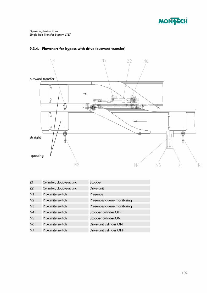
Operating Instructions Single-belt Transfer System LTE®
109
9.3.4. Flowchart for bypass with drive (outward transfer)
outward transfer straight
Z1 Cylinder, double-acting Stopper
Z2 Cylinder, double-acting Drive unit
N1 Proximity switch Presence
N2 Proximity switch Presence/ queue monitoring
N3 Proximity switch Presence/ queue monitoring
N4 Proximity switch Stopper cylinder OFF
N5 Proximity switch Stopper cylinder ON
N6 Proximity switch Drive unit cylinder ON
N7 Proximity switch Drive unit cylinder OFF
queuing

Operating Instructions Single-belt Transfer System LTE®
110
Start
Z1 OFF
N4 assigned
Z2 ON
noyes
N6 assigned
N1 unassigned
outwardtransfer
N1 assigned
no
no
yes
yes
outwardtransfer
T expired
N5 assigned
N3 unassigned
Z1 OFF
T delay time
Z1 ON
N4 assignedno
no
no
no
no
yes
yes
yes
yes
yes
yes
yes
no
N1 assigned
T expired
N5 assigned
N2 unassigned
Z1 OFF
T delay time
Z1 ON
N4 assignedno
no
no
no
no
yes
yes
yes
yes
yes
yes
N7 assigned
Z2 OFF
no
yesstraight
yes
no
no
noyes
N2 unassigned
no
N3 unassigned
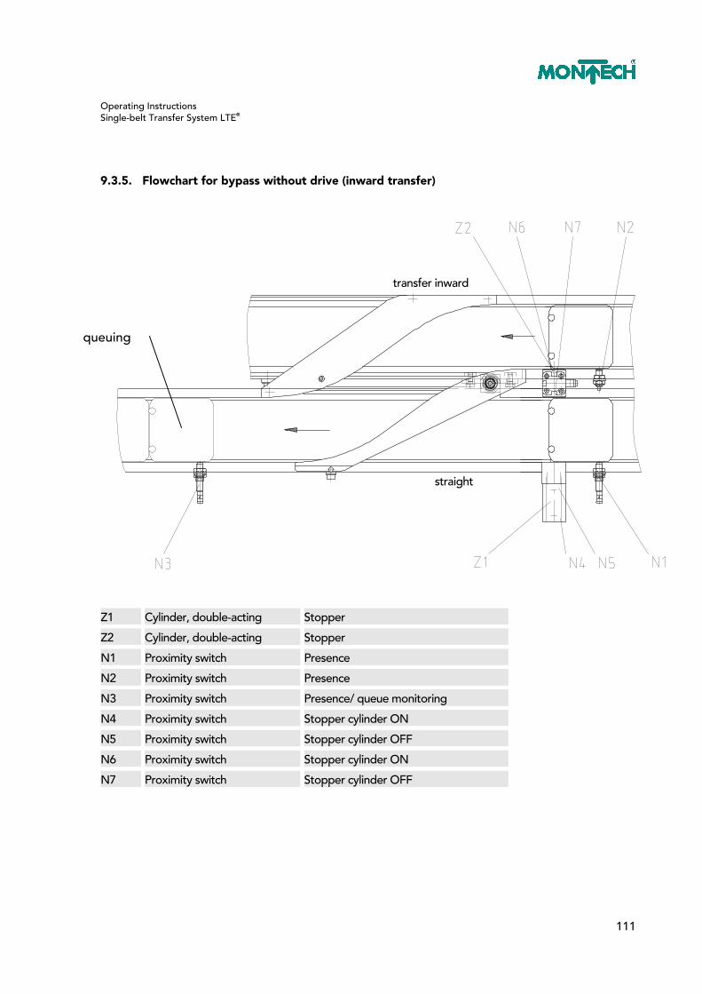
Operating Instructions Single-belt Transfer System LTE®
111
9.3.5. Flowchart for bypass without drive (inward transfer)
transfer inward straight
Z1 Cylinder, double-acting Stopper
Z2 Cylinder, double-acting Stopper
N1 Proximity switch Presence
N2 Proximity switch Presence
N3 Proximity switch Presence/ queue monitoring
N4 Proximity switch Stopper cylinder ON
N5 Proximity switch Stopper cylinder OFF
N6 Proximity switch Stopper cylinder ON
N7 Proximity switch Stopper cylinder OFF
queuing

Operating Instructions Single-belt Transfer System LTE®
112
Start
Z1 OFF
N5 assignedno
yes
N2 unassigned
N3 unassigned
inward transfer
N2 assigned
no
inwardtransfer
T expired
N6 assigned
N3 unassigned
Z2 OFF
T delay time
Z2 ON
N7 assignedno
no
no
no
no
yes
yes
yes
yes
yes
yes
yes
no
N1 assigned
T expired
N4 assigned
N3 unassigned
Z1 OFF
T delay time
Z1 EIN
N5 assignedno
no
no
no
no
yes
yes
yes
yes
yes
yes
yesstraight
yes
no
no
noyes
Z2 OFF
N7 assigned
N1 unassigned
no
no
yes
yes
yes

Operating Instructions Single-belt Transfer System LTE®
113
9.3.6. Flowchart for bypass with drive (inward transfer)
transfer inward straight
Z1 Cylinder, double-acting Stopper
Z2 Cylinder, double-acting Stopper
Z3 Cylinder, double-acting Drive unit
N1 Proximity switch Presence
N2 Proximity switch Presence
N3 Proximity switch Presence/ queue monitoring
N4 Proximity switch Stopper cylinder ON
N5 Proximity switch Stopper cylinder OFF
N6 Proximity switch Stopper cylinder ON
N7 Proximity switch Stopper cylinder OFF
N8 Proximity switch Drive unit cylinder OFF
N9 Proximity switch Drive unit cylinder ON
queuing

Operating Instructions Single-belt Transfer System LTE®
114
Start
Z1 OFF
N5 assigned
Z3 ON
no
yes
N2 unassigned
N9 assigned
N3 unassigned
inward transfer
N2 assigned
no
no
yes
yes
inwardtransfer
T expired
N6 assigned
N3 unassigned
Z2 OFF
T delay time
Z2 ON
N7 assignedno
no
no
no
no
yes
yes
yes
yes
yes
yes
yes
no
N1 assigned
T expired
N4 assigned
N3 unassigned
Z1 OFF
T delay time
Z1 ON
N5 assignedno
no
no
no
no
yes
yes
yes
yes
yes
yes
N8 assigned
Z3 OFF
no
yesstraight
yes
no
no
noyes
Z2 OFF
N7 assigned
N1 unassigned
no
noyes
yes

Operating Instructions Single-belt Transfer System LTE®
115
9.4. Maintenance and Repairs
9.4.1. Replacing the drive cylinder
– Turn off system. – Bleed compressed air system. – Remove the two pneumatic hoses (150) from the exhaust air valve (110). – Release clip (90/2) and pull down out of the fork end (90/1). – Swivel cylinder (100/1) out. – Remove retaining ring (170). – Remove cylinder (100/1). – Remove the fork end (90/1) and exhaust air valve (110) from the defective cylinder and mount on the new cylinder. Care must be taken to screw the fork end back to its original size. – Assemble in the reverse order. – Check swivel angles and reset, if necessary.

Operating Instructions Single-belt Transfer System LTE®
116
9.4.2. Checking and setting the swivel angle
– Extend cylinder. – The curve lever for bypass (60) must be on position 2. – Check if the curve lever for bypass applies noticeable pressure to the stop (40). – If yes, continue with point 16; if not, continue with point 5. – Turn off system. – Bleed compressed air system. – Release clip (90/2) and pull down out of the fork end (90/1). – Swivel cylinder (100/1) out. – Loosen hex nut (100/2). – Loosen fork end approx. ½ turn. – Tighten hex nut (100/2). – Swivel cylinder (100/1) in. – Mount clip (90/2). – Turn on system. – Perform steps 1 to 3. – Retract cylinder. – The curve lever for bypass (60) must be on position 1. – Check if the curve lever for bypass applies noticeable pressure to the stop (30). – If not, the procedure is the same as starting with point 6; except in point 10, the fork end must be screwed in ½ turn.
Schwenkwinkel = swivel angles

Operating Instructions Single-belt Transfer System LTE®
117
9.4.3. Replacing the drive unit
– Turn off system. – Bleed compressed air system. – Loosen countersunk screw (120) and washer (140) and remove. – Pull curve lever up and out. – Remove pad (70). – Loosen and remove the three screws (130). – Remove curve for bypass (50). – Loosen the two hex screws (40) and slide sideways out of the chassis binder (20). – Remove endless belt so that the hex screws (30) can be unscrewed. – Mark the position of the drive unit on the bearing and its angle. (This is to circumvent aligning the drive unit.) – Unscrew the four hex screws (30). – Replace drive unit (10) and reinstall in the location marked. – Assemble in the reverse order. – Check swivel angles and reset, if necessary.

Operating Instructions Single-belt Transfer System LTE®
118
9.5. Exploded Views / Spare Parts Lists
9.5.1. Bypass with drive

Operating Instructions Single-belt Transfer System LTE®
119
9.5.2. Spare parts list bypass right and left with drive
Item Sym. Name Item no. Material
TB-105 TB-140 TB-185 TB-250
◘ Bypass right 54493 54565 54569 56358 Various
◘ Bypass left 54632 54567 54571 56359 Various
10 ◊ Drive 54486 54486 54486 54486 Various
20 ◊ Chassis binder 54607 54607 54607 54607 Various
30 ◊ Stop 54630 54630 54630 54630 Steel
40 ◊ Pneumatic hose ø6/4 502745 502745 502745 502745 PU
50 ● Curve right 54490 54523 54526 56290 PE
50 ● Curve left 54489 54522 54525 56288 PE
60 ● Curve lever right 54491 54521 54524 56438 PA/aluminum
60 ● Curve lever left 54491 54521 54524 56289 PA/aluminum
70 ◊ Pad D=25 54484 54484 54484 54484 Steel
80 ◊ Support 54487 54529 54530 - Steel
90 ◊ Buffer 54497 54497 54497 54497 PUR
100 ◘ T-nut 21913 21913 21913 - Steel
110 ◊ Hex screw with ribs M6x10
508376 508376 508376 - Steel
120 ◊ Countersunk screw M6x10 506710 506710 506710 506710 Steel
130 ◊ Countersunk screw M5x20 501814 501814 501814 501814 Steel
140 ◊ Thread-forming oval head screw M4x20
508972 508972 508972 508972 Steel
150 ◊ Setscrew washer M6 504380 504380 504380 504380 Steel
● These are wearing parts and available ex stock. ◊ Not available ex stock individually (upon request) ◘ Price list item available ex stock

Operating Instructions Single-belt Transfer System LTE®
120
9.5.3. Bypass without drive

Operating Instructions Single-belt Transfer System LTE®
121
9.5.4. Spare parts list bypass right and left without drive
Item Sym. Name Item no. Material
TB-105 TB-140 TB-185 TB-250
◘ Bypass right 54494 54566 54570 56360 Various
◘ Bypass left 54564 54568 54572 56361 Various
10 ◊ Bearing 54496 54496 54496 54496 Various
20 ◊ Chassis binder 54607 54607 54607 54607 Various
30 ◊ Stop 54630 54630 54630 54630 Steel
40 ◊ Pneumatic hose ø6/4 502745 502745 502745 502745 PU
50 ● Curve right 54490 54523 54526 56290 PE
50 ● Curve left 54489 54522 54525 56288 PE
60 ● Curve lever right 54491 54521 54524 56438 PA/aluminum
60 ● Curve lever left 54491 54521 54524 56289 PA/aluminum
70 ◊ Pad D=25 54484 54484 54484 54484 Steel
80 ◊ Support 54487 54529 54530 - Steel
90 ◊ Buffer 54497 54497 54497 54497 PUR
100 ◘ T-nut 21913 21913 21913 - Steel
110 ◊ Hex screw with ribs M6x10
508376 508376 508376 - Steel
120 ◊ Countersunk screw M6x10 506710 506710 506710 506710 Steel
130 ◊ Countersunk screw M5x20 501814 501814 501814 501814 Steel
140 ◊ Thread-forming oval head screw M4x20
508972 508972 508972 508972 Steel
150 ◊ Setscrew washer M6 504380 504380 504380 504380 Steel
● These are wearing parts and available ex stock. ◊ Not available ex stock individually (upon request) ◘ Price list item available ex stock

Operating Instructions Single-belt Transfer System LTE®
122
9.5.5. Drive for bypass

Operating Instructions Single-belt Transfer System LTE®
123
9.5.6. Spare parts list drive for bypass (54486)
Item Sym. Name Item no. Material
10 ◊ Holder 56366 Steel
20 ◊ Shaft 56367 Steel
30 ◊ Angle 54483 Steel
40 ◊ Peg 54485 Steel
50 ◊ Lever 54488 Steel
60 ◘ T-nut 21913 Steel
70 ● Deep groove ball bearing 520036 Steel
80 ● Fork end SG-M6 503616 Steel
90 ● ISO cylinder CD85N16-40B SMC 508373 Steel
100 ◊ Ex air valve fitting M5 505023 Steel
110 ◊ Hex screw M6x12 508372 Steel
120 ◊ Countersunk screw M5x10 504901 Steel
130 ◊ Setscrew washer M5 504381 Steel
150 ◊ Retaining ring ø10 502448 Steel
160 ◊ Retaining ring ø6 502444 Steel
170 ◊ Warning sign 54792 Steel
● These are wearing parts and available ex stock. ◊ Not available ex stock individually (upon request) ◘ Price list item available ex stock
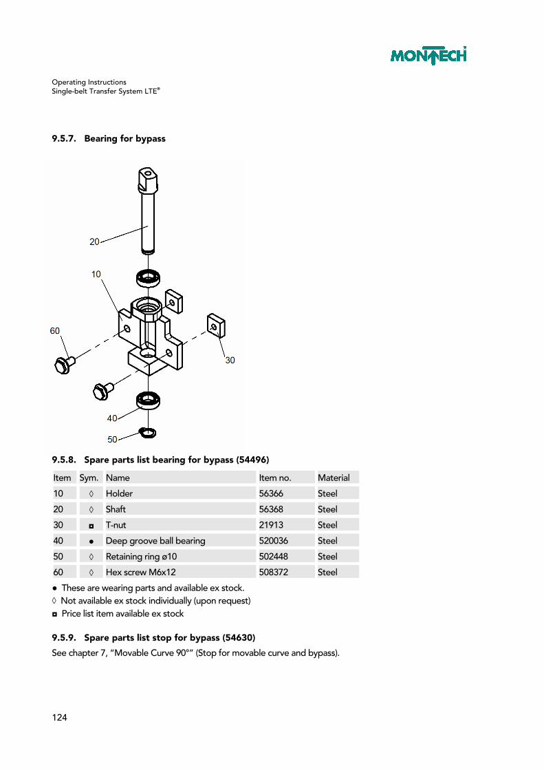
Operating Instructions Single-belt Transfer System LTE®
124
9.5.7. Bearing for bypass
9.5.8. Spare parts list bearing for bypass (54496)
Item Sym. Name Item no. Material
10 ◊ Holder 56366 Steel
20 ◊ Shaft 56368 Steel
30 ◘ T-nut 21913 Steel
40 ● Deep groove ball bearing 520036 Steel
50 ◊ Retaining ring ø10 502448 Steel
60 ◊ Hex screw M6x12 508372 Steel
● These are wearing parts and available ex stock. ◊ Not available ex stock individually (upon request) ◘ Price list item available ex stock
9.5.9. Spare parts list stop for bypass (54630)
See chapter 7, “Movable Curve 90°” (Stop for movable curve and bypass).
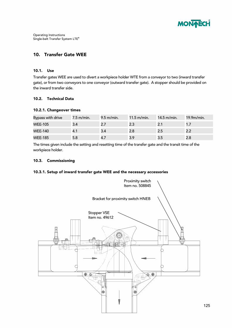
Operating Instructions Single-belt Transfer System LTE®
125
10. Transfer Gate WEE
10.1. Use
Transfer gates WEE are used to divert a workpiece holder WTE from a conveyor to two (inward transfer gate), or from two conveyors to one conveyor (outward transfer gate). A stopper should be provided on the inward transfer side.
10.2. Technical Data
10.2.1. Changeover times
Bypass with drive 7.5 m/min. 9.5 m/min. 11.5 m/min. 14.5 m/min. 19.9m/min.
WEE-105 3.4 2.7 2.3 2.1 1.7
WEE-140 4.1 3.4 2.8 2.5 2.2
WEE-185 5.8 4.7 3.9 3.5 2.8
The times given include the setting and resetting time of the transfer gate and the transit time of the workpiece holder.
10.3. Commissioning
10.3.1. Setup of inward transfer gate WEE and the necessary accessories
Stopper VSE Item no. 49612
Bracket for proximity switch HNEB
Proximity switch Item no. 508845

Operating Instructions Single-belt Transfer System LTE®
126
10.3.2. Setup of outward transfer gate WEE and the necessary accessories
Stopper VSE Item no. 49612
Bracket for proximity switch HNEB Item no. 54634
Proximity switch Item no. 508845

Operating Instructions Single-belt Transfer System LTE®
127
10.3.3. Checking and setting the drive unit
– The drive unit (10) must be installed centered (=) to the incoming chassis. – The axle must be at a right angle to the chassis. – Between the transfer gate (20), the lateral guides, and the inside curve (30) should be a space of 1 mm. – If that is not the case, the drive unit (10) must be set to the specified values by loosening the two screws (100). – Check if the transfer gate (20) applies noticeable pressure to the stop (70), both on the left and right sides. – If not, reset the swivel angle.
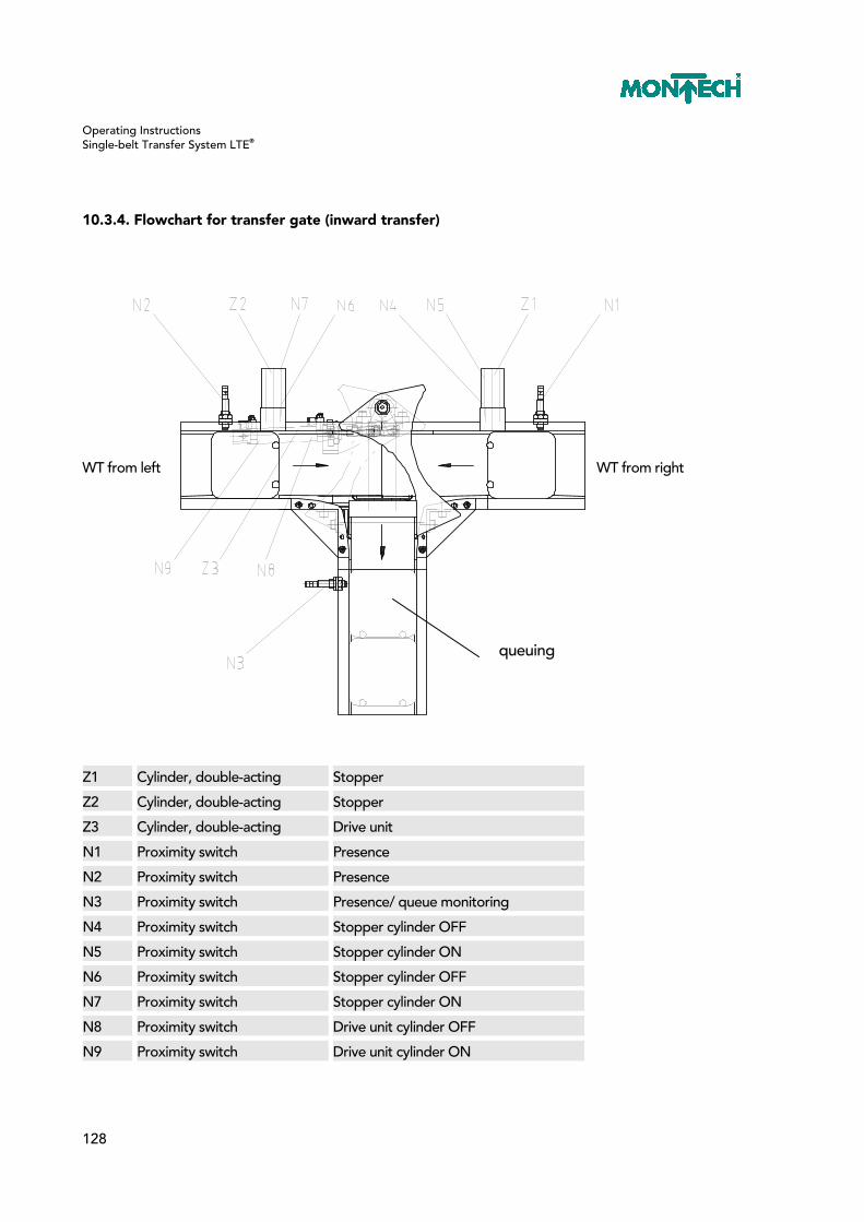
Operating Instructions Single-belt Transfer System LTE®
128
10.3.4. Flowchart for transfer gate (inward transfer)
WT from left WT from right
Z1 Cylinder, double-acting Stopper
Z2 Cylinder, double-acting Stopper
Z3 Cylinder, double-acting Drive unit
N1 Proximity switch Presence
N2 Proximity switch Presence
N3 Proximity switch Presence/ queue monitoring
N4 Proximity switch Stopper cylinder OFF
N5 Proximity switch Stopper cylinder ON
N6 Proximity switch Stopper cylinder OFF
N7 Proximity switch Stopper cylinder ON
N8 Proximity switch Drive unit cylinder OFF
N9 Proximity switch Drive unit cylinder ON
queuing

Operating Instructions Single-belt Transfer System LTE®
129
Start
Z1 OFF
N4 assigned
Z2 OFF
noyes
N6 assigned
N3 unassigned
WT from left
N2 assigned
no
no
yes
yes
WT from left
T expired
N7 assigned
N3 unassigned
Z2 OFF
T delay time
Z2 ON
N6 assignedno
no
no
no
no
yes
yes
yes
yes
yes
yes
yes
no
N1 assigned
T expired
N5 assigned
N3 unassigned
Z1 OFF
T delay time
Z1 ON
N4 assignedno
no
no
no
no
yes
yes
yes
yes
yes
yes
N9 assigned
Z3 ON
no
yesWT from right
yes
no
no
Z3 OFF
N8 assigned

Operating Instructions Single-belt Transfer System LTE®
130
10.3.5. Flowchart for transfer gate (outward transfer)
WT to the left WT to the right
Z1 Cylinder, double-acting Stopper
Z2 Cylinder, double-acting Drive unit
N1 Proximity switch Presence
N2 Proximity switch Presence/ queue monitoring
N3 Proximity switch Presence/ queue monitoring
N4 Proximity switch Stopper cylinder OFF
N5 Proximity switch Stopper cylinder ON
N6 Proximity switch Drive unit cylinder OFF
N7 Proximity switch Drive unit cylinder ON
queuing
queuing

Operating Instructions Single-belt Transfer System LTE®
131
Start
Z1 OFF
N4 assigned
Z2 OFF
no
yes
N2 unassigned
N6 assigned
N3 unassigned
WT to left
N1 assigned
no
no
yes
yes
WT to left
T expired
N5 assigned
N3 unassigned
Z1 OFF
T delay time
Z1 ON
N4 assignedno
no
no
no
no
yes
yes
yes
yes
yes
yes
yes
no
N1 assigned
T expired
N5 assigned
N2 unassigned
Z1 OFF
T delay time
Z1 ON
N4 assignedno
no
no
no
no
yes
yes
yes
yes
yes
yes
N7 assigned
Z2 ON
no
yesWT to right
yes
no
no
noyes

Operating Instructions Single-belt Transfer System LTE®
132
10.4. Maintenance and Repairs
10.4.1. Replacing the drive cylinder
See chapter 7, “Movable Curve 90°
10.4.2. Replacing the drive unit
– Turn off system. – Bleed compressed air system. – Loosen countersunk screw (110) and remove together with washer (140). – Pull transfer gate (20) up and out. – Remove pad (40). – Loosen the two screws (130) and remove. – Replace drive unit (10). – Assemble in the reverse order. – Check swivel angles and reset, if necessary.
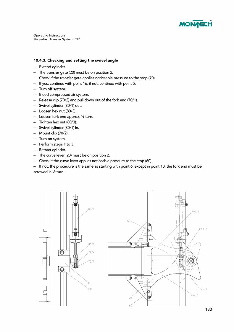
Operating Instructions Single-belt Transfer System LTE®
133
10.4.3. Checking and setting the swivel angle
– Extend cylinder. – The transfer gate (20) must be on position 2. – Check if the transfer gate applies noticeable pressure to the stop (70). – If yes, continue with point 16; if not, continue with point 5. – Turn off system. – Bleed compressed air system. – Release clip (70/2) and pull down out of the fork end (70/1). – Swivel cylinder (80/1) out. – Loosen hex nut (80/3). – Loosen fork end approx. ½ turn. – Tighten hex nut (80/3). – Swivel cylinder (80/1) in. – Mount clip (70/2). – Turn on system. – Perform steps 1 to 3. – Retract cylinder. – The curve lever (20) must be on position 2. – Check if the curve lever applies noticeable pressure to the stop (60). – If not, the procedure is the same as starting with point 6; except in point 10, the fork end must be screwed in ½ turn.

Operating Instructions Single-belt Transfer System LTE®
134
10.5. Exploded Views / Spare Parts Lists
10.5.1. Transfer gate

Operating Instructions Single-belt Transfer System LTE®
135
10.5.2. Spare parts list transfer gate
Item Sym. Name Item no. Material
TB-105 TB-140 TB-185
◘ Transfer gate 54789 54790 54791 Various
10 ◊ Drive 54502 54502 54502 Various
20 ● Transfer gate 54515 54516 54517 PA.
30 ● Transfer gate 54518 54512 54520 PE
40 ◊ Pad D=32 54501 54501 54501 Steel
50 ◊ Fastening bracket 54547 54547 54547 Steel
60 ● Finger protection device 49641 49642 49643 PE
70 ◊ Pneumatic hose ø6/4 502745 502745 502745 PU
80 ◘ T-nut 21913 21913 21913 Steel
100 ◊ Cheese head screws M6x12 504644 504644 504644 Steel
110 ◊ Countersunk screw M6x10 506710 506710 506710 Steel
120 ◊ Thread-forming Oval head screws M4x20
508972 508972 508972 Steel
130 ◊ Ribbed washer M6 505255 505255 505255 Steel
140 ◊ Setscrew washer M6 504380 504380 504380 Steel
150 ◊ Countersunk screw M5x20 501814 501814 501814 Steel
● These are wearing parts and available ex stock. ◊ Not available ex stock individually (upon request) ◘ Price list item available ex stock
10.5.3. Spare parts list drive for transfer gate (54502)
See chapter 7, “Movable Curve 90°” (spare parts list drive for curve)
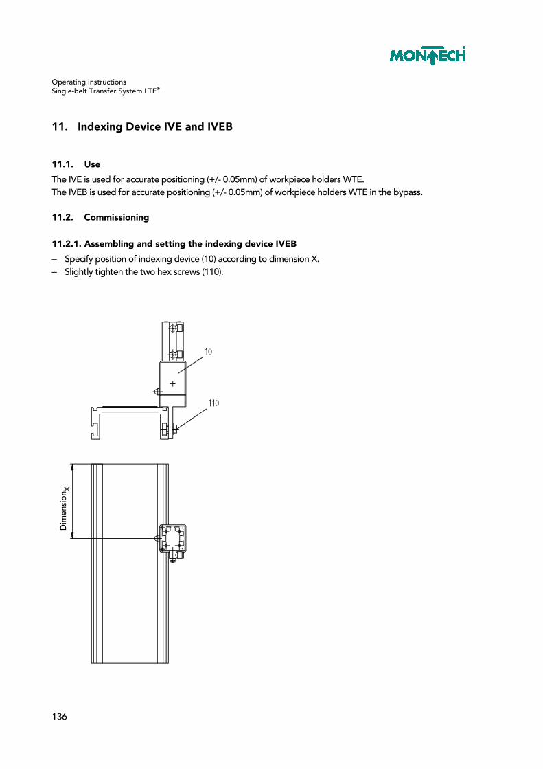
Operating Instructions Single-belt Transfer System LTE®
136
11. Indexing Device IVE and IVEB
11.1. Use
The IVE is used for accurate positioning (+/- 0.05mm) of workpiece holders WTE. The IVEB is used for accurate positioning (+/- 0.05mm) of workpiece holders WTE in the bypass.
11.2. Commissioning
11.2.1. Assembling and setting the indexing device IVEB
– Specify position of indexing device (10) according to dimension X. – Slightly tighten the two hex screws (110).
Dim
ensi
on

Operating Instructions Single-belt Transfer System LTE®
137
– Place a 0.2-0.3 mm thick feeler gauge strip on the belt. – Place WTE on the feeler gauge strip and - using the positioning sleeve in the WTE - align with the indexing stopper (10). – Mount pressure pad IVE (40) and slightly tighten Allen screws (50). – Center pressure pad IVE (40) relative to WTE. – Remove feeler gauge strip. – Use a feeler gauge between belt and WTE to check if the WTE is positioned horizontally. – Align WTE with adjustment screws (60/120). – Tighten fastening screws (50/110) with a torque of MA=6Nm.

Operating Instructions Single-belt Transfer System LTE®
138
– Mount left stopper (30) and lightly tighten the two hex screws (110). – The stopper (30) must be aligned so that a 0.1-0.3 mm play remains between the WTE recess and the stopper lock in an indexed WTE. – Tighten fastening screws (110).

Operating Instructions Single-belt Transfer System LTE®
139
– Mount right stopper (20) and lightly tighten the two hex screws (110). – The stopper (20) must be aligned so that a play of at least 2 mm remains between the indexed WTE and the following WTE. – Tighten fastening screws (110). – Connect compressed air system with maximum 6 bar

Operating Instructions Single-belt Transfer System LTE®
140
– Screw on the two brackets for proximity switch HNEB (70), item no. 49629, using hex screw (90). – Mount proximity switch (80), item no. 508377, in bracket for proximity switch. – Align proximity switch with engagement pin in WTE. – The switching distance should be set to 0.5-1 mm to the WTE .
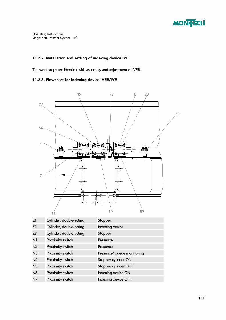
Operating Instructions Single-belt Transfer System LTE®
141
11.2.2. Installation and setting of indexing device IVE
The work steps are identical with assembly and adjustment of IVEB.
11.2.3. Flowchart for indexing device IVEB/IVE
Z1 Cylinder, double-acting Stopper
Z2 Cylinder, double-acting Indexing device
Z3 Cylinder, double-acting Stopper
N1 Proximity switch Presence
N2 Proximity switch Presence
N3 Proximity switch Presence/ queue monitoring
N4 Proximity switch Stopper cylinder ON
N5 Proximity switch Stopper cylinder OFF
N6 Proximity switch Indexing device ON
N7 Proximity switch Indexing device OFF

Operating Instructions Single-belt Transfer System LTE®
142
Start
Z1 OFF
N5 assigned
Z2 ON
noyes
N6 assigned
N1 unassigned
N2 assigned
no
no
yes
yes
T2 expired
N3 unassigned
N7 assigned
T2 delay time
Z2 OFF
no
no
no
no
no
yes
yes
yes
yes
yes
yes
no
N4 assigned
N9 assigned
Z1 ON
Z3 OFF
N5 assigned
N2 unassigned
no
no
no
no
no
yes
yes
yes
yes
yes
yes
N3 unassigned
Z2 ON
noyes
no
Z3 ON
N8 assigned
N2 unassigned
yes
N6 assigned
Z1 OFF
Z3 ON
N9 assigned
N8 assigned
no
yes
yes
N1 assigned
Z3 OFF
no
N2 assignedno
yes
T1 delay time
T1 expired
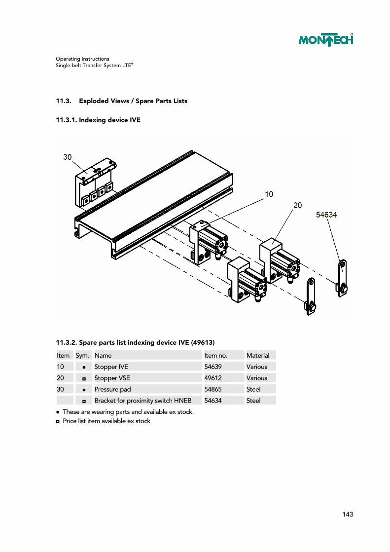
Operating Instructions Single-belt Transfer System LTE®
143
11.3. Exploded Views / Spare Parts Lists
11.3.1. Indexing device IVE
11.3.2. Spare parts list indexing device IVE (49613)
Item Sym. Name Item no. Material
10 ● Stopper IVE 54639 Various
20 ◘ Stopper VSE 49612 Various
30 ● Pressure pad 54865 Steel
◘ Bracket for proximity switch HNEB 54634 Steel
● These are wearing parts and available ex stock. ◘ Price list item available ex stock

Operating Instructions Single-belt Transfer System LTE®
144
11.3.3. Indexing device IVEB right and left
11.3.4. Spare parts list indexing device IVEB right (54492)
Item Sym. Name Item no. Material
10 ● Indexing device IEB right 54582 Various
20 ◘ Stopper VSEB right 54601 Various
30 ◘ Stopper VSEB left 54581 Various
40 ● Pressure pad 54865 Steel
◘ Bracket for proximity switch HNEB 54634 Steel
● These are wearing parts and available ex stock. ◘ Price list item available ex stock
Operating Instructions Single-belt Transfer System LTE®
145
11.3.5. Spare parts list indexing device IVEB left (54633)
Item Sym. Name Item no. Material
10 ● Indexing device IEB left 54602 Various
20 ◘ Stopper VSEB left 54581 Various
30 ◘ Stopper VSEB right 54601 Various
40 ● Pressure pad 54865 Steel
◘ Bracket for proximity switch HNEB 54634 Steel
● These are wearing parts and available ex stock. ◘ Price list item available ex stock

Operating Instructions Single-belt Transfer System LTE®
146
12. Positioning Device PVE
12.1. Use
The PVE is used for accurate positioning (+/- 0.05mm) of workpiece holders WTE, which are supported from below for press-in operations.
12.2. Technical Data
12.2.1. Maximum torque
WTE 80x80 Center 4Nm Diamete 0 to 30 3.5Nm 30 to 60 3Nm WTE 115x115 Center 6Nm Diameter 0 to 40 4.5Nm 40 to 80 3Nm

Operating Instructions Single-belt Transfer System LTE®
147
WTE 160x160 Center 6.5Nm Diameter 0 to 60 5.5Nm 60 to 120 5Nm WTE 225x225 Center 7Nm Diameter 0 to 90 6Nm 90 to 180 5.5Nm
Operating Instructions Single-belt Transfer System LTE®
148
12.3. Commissioning
12.3.1. Mounting and setting positioning device PVE
– Insert support with belt stroke cylinder (10) in chassis. – Support position (10) from below. – Align support (10) centered to recess. – Center the stoppers (20) against the recess in the chassis. – Slightly tighten the two screws (60).
Abstützung = Support

Operating Instructions Single-belt Transfer System LTE®
149
– Retract the two belt stroke cylinders (150) so that the belt is free. – Place WTE on the support and - using the positioning sleeve in the WTE - align with the stopper (20). – Mount pressure pad PVE (30) and align centrically with WTE; slightly tighten screws (70). – Use the stopper (20) to index the WTE. – Use a feeler gauge between support (10) and WTE to check if the WTE makes contact with the support (10). – Align WTE with adjustment screws (80/90). Tighten fastening screws (60/70) with a torque of MA=6Nm.

Operating Instructions Single-belt Transfer System LTE®
150
– Mount left stopper (40) and lightly tighten the two screws (100). – The stopper (40) must be aligned so that a 0.1-0.3 mm play remains between the WTE recess and the stopper lock in an indexed WTE. – Tighten fastening screws (100) with a torque of MA=6Nm. – Mount right stopper (50) and lightly tighten the two screws (110). – The stopper (50) must be aligned so that a play of at least 2 mm remains between the indexed WTE and the following WTE. – Tighten fastening screws (110). – Connect compressed air system with maximum 6 bar.
Operating Instructions Single-belt Transfer System LTE®
151
– Screw on the two brackets for proximity switch HNEB (120), item no. 54634, using screw (140). – Mount proximity switch (130), item no. 508845, in bracket for proximity switch. – Align proximity switch to engagement pin in WTE. – The distance should be set to 0.5-1 mm to the WTE.

Operating Instructions Single-belt Transfer System LTE®
152
12.3.2. Flowchart for positioning device PVE
Z1 Cylinder, double-acting Stopper
Z2 Cylinder, double-acting Indexing device
Z3 Cylinder, double-acting Stopper
Z4 Cylinder, double-acting Belt stroke cylinder
Z5 Cylinder, double-acting Belt stroke cylinder
N1 Proximity switch Presence before PVE
N2 Proximity switch Presence in PVE
N3 Proximity switch Presence/ queue monitoring
N4 Proximity switch Stopper cylinder ON
N5 Proximity switch Stopper cylinder OFF
N6 Proximity switch Indexing device ON
N7 Proximity switch Indexing device OFF
N8 Proximity switch Stopper cylinder ON
N9 Proximity switch Stopper cylinder OFF

Operating Instructions Single-belt Transfer System LTE®
153
Start
Z1 OFF
N4 occupied
Z2 ON
noyes
N7 occupied
N1 occupiedno
no
yes
N7 occupied
N3 free
no
no
no
yes
yes
yesno
N6 occupied
Z4/Z5OFF
Z2 OFF
N4 occupiedno
noyes
yes
yes
Z1 ON
Z3 OFF
N8 occupied
N2 occupied
yes
N5 occupied
Z4/Z5OFF
Z2 ON
PROCESSING
Z1 OFF
END OFPROGR.
yes
no
Delay timeT2 for Z3
=0
no
yes
N8 occupied
N9 occupied
Z3 OFF
Z3 ON
yes
yes
no
no
Z4/Z5ON
END OFPROCES.
Delay timeT1 for Z1
=0
yes
no
END
yes
yes
nono

Operating Instructions Single-belt Transfer System LTE®
154
12.4. Exploded Views / Spare Parts Lists
12.4.1. Positioning device PVE
12.4.2. Spare parts list positioning device PVE
Item Sym. Name Item no. Material
TBD-105 TBD-140 TBD-185 TBD-250
◘ Positioning device PVE 55131 55132 55133 56507 Various
10 ◘ Stopper VSE 49612 49612 49612 49612 Various
20 ● Stopper IVE 54639 54639 54639 54639 Various
30 ● Pressure pad 55183 55159 55184 56309 Steel
40 ◊ Support with belt stroke cylinder 55185 55186 55187 56308 Various
◘ Proximity switch HNEB 54634 54634 54634 54634 Steel
● These are wearing parts and available ex stock. ◘ Price list item available ex stock

Operating Instructions Single-belt Transfer System LTE®
155
12.4.3. Support with belt stroke cylinder
12.4.4. Spare parts list support with belt stroke cylinder
Item Sym. Name Item no. Material
TBD-105 TBD-140 TBD-185 TBD-250
◘ Support with belt stroke cylinder 55185 55186 55187 56308 Various
10 ◊ Support 55111 55112 55113 56120 Steel
20 ● Belt stroke cylinder 55110 55110 55110 55110 Various
30 ◊ Cheese head screws M5x20 504799 504799 504799 504799 Steel
40 ◊ Ribbed washer M5 505254 505254 505254 505254 Steel
● These are wearing parts and available ex stock. ◊ Not available ex stock individually (upon request) ◘ Price list item available ex stock

Operating Instructions Single-belt Transfer System LTE®
156
13. Environmental Friendliness and Disposal
Raw materials used – Aluminum – Steel – Copper – PUR Polyurethane – ABS Acrylonitrile Butadiene Styrene copolymer – PS Polystyrol – HDPE Polyethylene – PVC Polyvinyl chloride – PET Polyethylene terephthalate – Gear lubricant, V < 4.02m/min. = soda soap Calypsol D 6024 – Gear lubricant, V > 5.26m/min. = Syntheso D 460 EP Surface treatment – Anodizing of aluminum – Electroless nickel-plating of steel Forming processes – Aluminum extrusion – Non-cutting machining of aluminum, steel, polyurethane and deep-drawing of Polystyrene – Injection molding of ABS – Steel laser-cutting Emissions during operation None Disposal Conveyors and their accessories that can no longer be used should not be recycled as entire units, but disassembled and then recycled according to the material types used. The material type of each component is listed in the spare parts lists. Material that cannot be recycled must be disposed of in the appropriate manner. Care should be taken to dispose of gear lubricants separately.

Betriebsanleitung Längstransfersystem LTE®
157
13. Umweltverträglichkeit und Entsorgung
Verwendete Rohmaterialien � Aluminium � Stahl � Kupfer � PUR Polyurethan � ABS Acrylnitril-Butadien-Styrol-Copolymer � PS Polystyrol � HDPE Polyethylen � PVC Polyvinylchlorid � PET Polyethylenterephtalat � Getriebeschmiermittel, V < 4.02m/min. = Natriumseifenfett Calypsol D 6024 � Getriebeschmiermittel, V > 5.26m/min. = Syntheso D 460 EP Oberflächenveredelung � Anodisieren von Aluminium � Stromloses vernickeln von Stahl Formgebungsprozesse � Profilpressen von Aluminium � Spanende Bearbeitung von Alu, Stahl, Polystyrol, Polyurethan und Tiefziehen von Polystyrol � Spritzguss aus ABS � LASER-schneiden von Stahl Emissionen während des Betriebes Keine Entsorgung Nicht mehr verwendbare Transportbänder und ihr Zubehör sollen nicht als ganze Einheiten, sondern demontiert in Einzelteile, nach Materialart rezykliert werden. Die Materialart jedes Einzelteils ist in den Ersatzteillisten aufgeführt. Nicht rezyklierbares Material soll artgerecht entsorgt werden. Speziell zu beachten ist die separate Entsorgung des Getriebeschmiermittels.