
TR 123 909 - V4.0.0 - Digital cellular telecommunications ... · ETSI TR 123 909 V4.0.0 ... 7.5.1.4...
62
ETSI TR 123 909 V4.0.0 (2001-03) Technical Report Digital cellular telecommunications system (Phase 2+) (GSM); Universal Mobile Telecommunications System (UMTS); Technical Report on the Gateway Location Register (3GPP TR 23.909 version 4.0.0 Release 4) GLOBAL SYSTEM FOR MOBILE COMMUNICATIONS R
Transcript of TR 123 909 - V4.0.0 - Digital cellular telecommunications ... · ETSI TR 123 909 V4.0.0 ... 7.5.1.4...
ETSI TR 123 909 V4.0.0 (2001-03)Technical Report
Digital cellular telecommunications system (Phase 2+) (GSM);Universal Mobile Telecommunications System (UMTS);
Technical Report on the Gateway Location Register(3GPP TR 23.909 version 4.0.0 Release 4)
GLOBAL SYSTEM FORMOBILE COMMUNICATIONS
R

1
ETSI
ETSI TR 123 909 V4.0.0 (2001-03)3GPP TR 23.909 version 4.0.0 Release 4
ReferenceRTR/TSGN-0423909Uv4
KeywordsGSM, UMTS
ETSI
650 Route des LuciolesF-06921 Sophia Antipolis Cedex - FRANCE
Tel.: +33 4 92 94 42 00 Fax: +33 4 93 65 47 16
Siret N° 348 623 562 00017 - NAF 742 CAssociation à but non lucratif enregistrée à laSous-Préfecture de Grasse (06) N° 7803/88
Important notice
Individual copies of the present document can be downloaded from:http://www.etsi.org
The present document may be made available in more than one electronic version or in print. In any case of existing orperceived difference in contents between such versions, the reference version is the Portable Document Format (PDF).
In case of dispute, the reference shall be the printing on ETSI printers of the PDF version kept on a specific network drivewithin ETSI Secretariat.
Users of the present document should be aware that the document may be subject to revision or change of status.Information on the current status of this and other ETSI documents is available at http://www.etsi.org/tb/status/
If you find errors in the present document, send your comment to:[email protected]
Copyright Notification
No part may be reproduced except as authorized by written permission.The copyright and the foregoing restriction extend to reproduction in all media.
© European Telecommunications Standards Institute 2001.
All rights reserved.

2
ETSI
ETSI TR 123 909 V4.0.0 (2001-03)3GPP TR 23.909 version 4.0.0 Release 4
Intellectual Property RightsIPRs essential or potentially essential to the present document may have been declared to ETSI. The informationpertaining to these essential IPRs, if any, is publicly available for ETSI members and non-members, and can be foundin ETSI SR 000 314: "Intellectual Property Rights (IPRs); Essential, or potentially Essential, IPRs notified to ETSI inrespect of ETSI standards", which is available from the ETSI Secretariat. Latest updates are available on the ETSI Webserver (http://www.etsi.org/ipr).
Pursuant to the ETSI IPR Policy, no investigation, including IPR searches, has been carried out by ETSI. No guaranteecan be given as to the existence of other IPRs not referenced in ETSI SR 000 314 (or the updates on the ETSI Webserver) which are, or may be, or may become, essential to the present document.
ForewordThis Technical Report (TR) has been produced by the ETSI 3rd Generation Partnership Project (3GPP).
The present document may refer to technical specifications or reports using their 3GPP identities, UMTS identities orGSM identities. These should be interpreted as being references to the corresponding ETSI deliverables.
The cross reference between GSM, UMTS, 3GPP and ETSI identities can be found under www.etsi.org/key .

ETSI
ETSI TR 123 909 V4.0.0 (2001-03) 33GPP TR 23.909 version 4.0.0 Release 4
Contents
Foreword............................................................................................................................................................ 5
1 Scope ....................................................................................................................................................... 6
2 References ............................................................................................................................................... 6
3 Definitions and abbreviations.................................................................................................................. 6 3.1 Definitions ..........................................................................................................................................................6 3.2 Abbreviations .....................................................................................................................................................6
4 Introduction ............................................................................................................................................. 7
5 Roaming Scenarios.................................................................................................................................. 7 5.1 Relationship between GLR and HLR.................................................................................................................7 5.2 Relationship between GLR and VLR.................................................................................................................7
6 Logical Network Model .......................................................................................................................... 8 6.1 GLR....................................................................................................................................................................8 6.2 Intermediate MSC ..............................................................................................................................................9 6.3 Intermediate GSN...............................................................................................................................................9 6.4 Gate Node...........................................................................................................................................................9
7 Functional Description ............................................................................................................................ 9 7.1 Generic Functions...............................................................................................................................................9 7.1.1 Message Relay Functions .............................................................................................................................9 7.1.2 Address Conversion Function.....................................................................................................................10 7.1.3 Subscriber Information Caching Function ..................................................................................................10 7.1.4 Subscriber Information Cancellation Function ...........................................................................................10 7.1.5 HLR emulation Function ............................................................................................................................10 7.1.6 Location Updating Screening Function ......................................................................................................10 7.1.7 Location Updating Screening Function ......................................................................................................10 7.2 Circuit Switched Service ..................................................................................................................................11 7.2.1 Location Update Procedure.........................................................................................................................11 7.2.1.1 First Location Updating ........................................................................................................................11 7.2.1.2 Second and further Location Updating..................................................................................................12 7.2.1.3 Cancel Location ....................................................................................................................................12 7.2.1.4 Rate adaptation in the IWF....................................................................................................................13 7.2.1.5 Handling of unsupported service...........................................................................................................16 7.2.1.6 Address Conversion ..............................................................................................................................19 7.2.2 Routing Information Interrogation Procedure.............................................................................................19 7.2.3 Procedure for GSM/UMTS Message Delivery ...........................................................................................20 7.2.3.1 Transparent message Relay (type a)......................................................................................................20 7.2.3.2 Message delivery using MSC Number (type b) ....................................................................................20 7.2.3.3 Location Updating Screening (type c)...................................................................................................21 7.3 Packet Switched Service...................................................................................................................................22 7.3.1 Address Conversion Function.....................................................................................................................22 7.3.2 GPRS Attach Procedure involving GLR.....................................................................................................23 7.3.2.1 New SGSN served by GLR, old SGSN served by HLR .......................................................................23 7.3.2.2 New SGSN and old SGSN served by the same GLR............................................................................25 7.3.3 Authentication of Subscriber ......................................................................................................................26 7.3.4 Inter SGSN Routeing Area Update.............................................................................................................27 7.3.5 PDP Context Activation Procedure.............................................................................................................29 7.3.5.1 Successful Network-Requested PDP Context Activation Procedure with GLR ...................................30 7.3.5.2 Unsuccessful Network-Requested PDP Context Activation Procedure with GLR ...............................32 7.3.5.3 Synchronisation of the MNRG Flag......................................................................................................34 7.3.5.3.1 Case 1 - MNRG Flag in GLR is Reset.............................................................................................34 7.3.5.3.2 Case 2 - MNRG Flag is Set .............................................................................................................34 7.4 Common Procedures ........................................................................................................................................35 7.4.1 Authentication Information Retrieval Procedure ........................................................................................35 7.4.2 Purge MS ....................................................................................................................................................35

ETSI
ETSI TR 123 909 V4.0.0 (2001-03) 43GPP TR 23.909 version 4.0.0 Release 4
7.4.3 Restart .........................................................................................................................................................36 7.4.3.1 HLR Restart ..........................................................................................................................................36 7.4.3.2 VLR Restart ..........................................................................................................................................36 7.4.3.2.1 VLR Restart Procedure....................................................................................................................36 7.4.3.3 GLR Restart ..........................................................................................................................................37 7.4.3.3.1 GLR Restart Procedure....................................................................................................................38 7.4.3.4 SGSN Restart ........................................................................................................................................39 7.4.3.5 Restoration Indicator .............................................................................................................................39 7.5 Short Message Service .....................................................................................................................................39 7.5.1 Short Message Service Mobile Terminated ................................................................................................39 7.5.1.1 SMS MT over MSC (successful) ..........................................................................................................40 7.5.1.2 SMS MT over SGSN (successful).........................................................................................................41 7.5.1.3 SMS MT over both MSC and SGSN (attempt over MSC successes) ...................................................41 7.5.1.4 SMS MT over both MSC and SGSN (both attempts fail) .....................................................................42 7.5.2 SMS Alert Procedure initiated by Update Location or Update GPRS Location.........................................44 7.5.3 Alternatives for SMS Support Without the IM-MSC entity .......................................................................44 7.5.3.1 Alternative 1..........................................................................................................................................45 7.5.3.2 Alternative 2..........................................................................................................................................45 7.6 Subscriber and Equipment Trace......................................................................................................................45 7.7 Impact of GLR on CAMEL..............................................................................................................................45 7.8 Interaction With CCBS.....................................................................................................................................46 7.9 Location Service (LCS) ....................................................................................................................................47
8 Mobile terminating Location Request Subscriber Information ............................................................. 47 8.1 Information for HLR emulation .......................................................................................................................48 8.2 Information for address and identity conversion ..............................................................................................48 8.3 Information for Location updating Screening ..................................................................................................48 8.4 Other Information.............................................................................................................................................49 8.5 IMSI Record in GLR........................................................................................................................................50
9 Percentage reduction of Inter-PLMN MAP traffic................................................................................ 52 9.1 Case 1: A businessman visits a large city.........................................................................................................52 9.1.1 Case 1a: The subscriber arrives at the destination ......................................................................................53 9.1.2 Case 1b:The subscriber has already registered as a roaming subscriber.....................................................54 9.2 Case 2: A tourist visits a large city for shopping..............................................................................................54 9.2.1 Case 2a: The subscriber arrives at the destination ......................................................................................55 9.2.2 Case 2b: The subscriber has already registered as a roaming subscriber....................................................55 9.3 Location Update ...............................................................................................................................................56
10 Interworking with existing GSM networks ........................................................................................... 57
11 Impact on GSM Release 99 Specifications ........................................................................................... 57
12 Advantages of the GLR......................................................................................................................... 58 12.1 Optimisation of MAP Traffic ...........................................................................................................................58 12.2 Interworking With GSM...................................................................................................................................58
13 Drawbacks of the GLR.......................................................................................................................... 58 13.1 Application level analysis of signalling............................................................................................................58 13.2 Reliability Issues ..............................................................................................................................................59 13.2.1 Reliability requirements..............................................................................................................................59 13.2.2 Effect on overall system reliability .............................................................................................................59 13.3 Upgrading of GLR capabilities.........................................................................................................................59 13.4 Handling of unsupported services ....................................................................................................................59 13.5 VLR Location Based Services..........................................................................................................................59
14 Open Issues............................................................................................................................................ 59 14.1 Additional signalling load on HLR restart........................................................................................................59
Annex A: Change history ..................................................................................................................... 60

ETSI
ETSI TR 123 909 V4.0.0 (2001-03) 53GPP TR 23.909 version 4.0.0 Release 4
Foreword This Technical Report (TR) has been produced by the 3rd Generation Partnership Project (3GPP).
The contents of the present document are subject to continuing work within the TSG and may change following formal TSG approval. Should the TSG modify the contents of the present document, it will be re-released by the TSG with an identifying change of release date and an increase in version number as follows:
Version x.y.z
where:
x the first digit:
1 presented to TSG for information;
2 presented to TSG for approval;
3 or greater indicates TSG approved document under change control.
y the second digit is incremented for all changes of substance, i.e. technical enhancements, corrections, updates, etc.
z the third digit is incremented when editorial only changes have been incorporated in the document.

ETSI
ETSI TR 123 909 V4.0.0 (2001-03) 63GPP TR 23.909 version 4.0.0 Release 4
1 Scope The present document describes the use of a Gateway Location Register within the UMTS Core Network as a means of reducing the amount of MAP signalling traffic associated with location management carried over inter-PLMN links for roaming users.
One of the requirements of the present document is to describe a network architecture where the presence of a GLR within a UMTS PLMN is not visible to either a second generation PLMN (i.e. GSM release 98 or earlier) or a 3G PLMN (i.e. GSM Release 99 or later). So the objective of this report is that changes to GSM specified interfaces or procedures will not be needed in order to:
- integrate a GLR into a UMTS PLMN;
- allow interworking between a GLR-enabled UMTS network and a GSM or UMTS network without a GLR.
The present document will be restricted to the study of the case where the GLR supports one VPLMN only. A separate TR will be required if support of multiple VPLMNs by the GLR is to be studied.
The present document will study support of multiple HPLMNs by the GLR.
2 References The following documents contain provisions which, through reference in this text, constitute provisions of the present document.
• References are either specific (identified by date of publication, edition number, version number, etc.) or non-specific.
• For a specific reference, subsequent revisions do not apply.
• For a non-specific reference, the latest version applies. In the case of a reference to a 3GPP document (including a GSM document), a non-specific reference implicitly refers to the latest version of that document in the same Release as the present document.
[1] GSM 01.04: "Digital cellular telecommunications system (Phase 2+); Abbreviations and acronyms".
3 Definitions and abbreviations
3.1 Definitions Gateway Location Register: This entity handles location management of roaming subscriber in visited network without involving HLR.
Intermediate MSC: This entity is used as serving MSC towards home network and relay some messages between serving MSC and home network.
3.2 Abbreviations GLR Gateway Location Register IM-MSC Intermediate MSC

ETSI
ETSI TR 123 909 V4.0.0 (2001-03) 73GPP TR 23.909 version 4.0.0 Release 4
4 Introduction UMTS will build on the success of GSM and is likely to become even more widespread. IMT-2000 networks based on GSM evolution are planned for Europe, Japan, USA and Korea. Coupled with steadily increasing rates of international travel for business and leisure, this means a significant increase in the number of roaming users needing to be supported. This will lead to increased signalling traffic on "short -haul" and "long-haul" international links. The introduction of CAMEL Phase 3 for UMTS will add CAP signalling to these international links, leading to a further signalling load increase over present day levels.
The GLR (Gateway Location Register) is a node between the VLR and the HLR, which may be used to optimise the handling of subscriber profile data across network boundaries. The GLR is functionally part of the roaming subscriber’s Home Environment. When a subscriber is roaming the GLR plays the role of the HLR towards the VLR in the visited network, and the role of the VLR towards the HLR in the home network. The GLR handles any location change between different VLR service areas in the visited network without involving the HLR. The GLR is an optional entity within the VPLMN operator’s network.
5 Roaming Scenarios Figure 1 shows that the GLR is deployed at the edge of visited network. It contains roamer’s subscriber profile and location information, and handles mobility management within the visited network.
The subscriber information is downloaded from HLR to GLR at the first location update procedure under the GLR. Using the information, GLR handles Update Location message from VLR as if it is the HLR of the subscriber at second and further location updating procedures. GLR enables the procedure invisible from the home network so that this hierarchical location management can reduce the inter-network signalling for the location management.
The GLR keeps the information until receiving Cancel Location message from HLR.
5.1 Relationship between GLR and HLR A GLR interacts with multiple HLRs, which will be located in different PLMNs. The relationship between the GLR and the HLR is the same as that between the VLR and the HLR.
The implication of supporting multiple HPLMNs is that the GLR will need to store a large amount of profile data.
5.2 Relationship between GLR and VLR A GLR interacts with multiple VLRs. For the purposes of this Technical Report, the GLR supports only one VPLMN. The support of multiple VPLMNs by the GLR is outside the scope of this Technical Report.
However, it is an assumption of this report that the proposed GLR architecture must not prevent future expansion to support multiple VPLMNs.
ETSI
ETSI TR 123 909 V4.0.0 (2001-03) 83GPP TR 23.909 version 4.0.0 Release 4
HLRHPLMN A HLR
GLR
VLR/SGSNVLR/SGSN
VPLMN a
HPLMN B HLR
GLR
VLR/SGSNVLR/SGSN
VPLMN b
HPLMN C
Figure 1: Possible Location of GLR
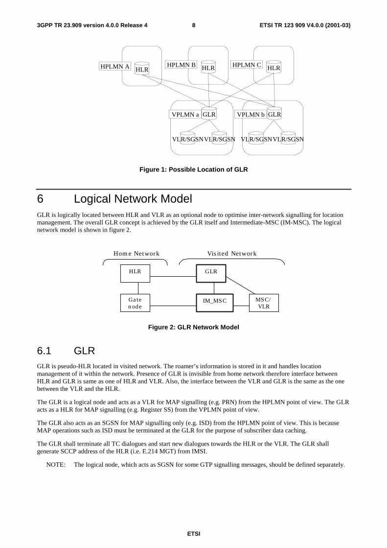
6 Logical Network Model GLR is logically located between HLR and VLR as an optional node to optimise inter-network signalling for location management. The overall GLR concept is achieved by the GLR itself and Intermediate-MSC (IM-MSC). The logical network model is shown in figure 2.
HLR
Gatenode
GLR
MSC/VLR
Home Network Visited Network
IM_MSC
Figure 2: GLR Network Model
6.1 GLR GLR is pseudo-HLR located in visited network. The roamer’s information is stored in it and handles location management of it within the network. Presence of GLR is invisible from home network therefore interface between HLR and GLR is same as one of HLR and VLR. Also, the interface between the VLR and GLR is the same as the one between the VLR and the HLR.
The GLR is a logical node and acts as a VLR for MAP signalling (e.g. PRN) from the HPLMN point of view. The GLR acts as a HLR for MAP signalling (e.g. Register SS) from the VPLMN point of view.
The GLR also acts as an SGSN for MAP signalling only (e.g. ISD) from the HPLMN point of view. This is because MAP operations such as ISD must be terminated at the GLR for the purpose of subscriber data caching.
The GLR shall terminate all TC dialogues and start new dialogues towards the HLR or the VLR. The GLR shall generate SCCP address of the HLR (i.e. E.214 MGT) from IMSI.
NOTE: The logical node, which acts as SGSN for some GTP signalling messages, should be defined separately.

ETSI
ETSI TR 123 909 V4.0.0 (2001-03) 93GPP TR 23.909 version 4.0.0 Release 4
6.2 Intermediate MSC The Intermediate MSC (IM-MSC) is the logical node, which represent MSCs in the visited network. Some service features use the MSC Number stored in the HLR directly to deliver message from a certain node in home network (e.g. SMS-GMSC) to serving MSC in visited network. In such case, the message is firstly distributed to representative MSC (i.e., IM-MSC) and it relays it to actual serving MSC interrogating routing information to GLR.
- The Intermediate MSC (IM-MSC) is a logical node and represents the VMSC in the GLR equipped VPLMN.
- The IM-MSC acts as the VMSC for the HPLMN in the same way that the GLR acts as a VLR for HPLMN. The IM-MSC terminates MAP signalling from the HPLMN towards the VMSC and forwards the signal to the actual VMSC.
- The IM-MSC has an address interrogation function with which it is able to obtain the actual VMSC Number from the GLR.
- The IM-MSC is implemented in the same physical node as the one in which the GLR is implemented.
- Whether the new entity IM-MSC should be defined is for further study.
- The GLR alters the VMSC Number to the IM-MSC Number within an Update Location message.
- The IM-MSC Number is the E.164 Number assigned to the IM-MSC.
- The interrogation function of the IM-MSC is similar to that in the SMS-GMSC.
6.3 Intermediate GSN The Intermediate GSN (IM-GSN) is a logical node and represents the SGSN for some GTP signalling termination in a GLR equipped VPLMN.
The IM-GSN acts as an SGSN for only some GTP signalling messages (i.e. PDU_Notification request/response, PDU_Notification_reject request/response) from the HPLMN. The IM-GSN terminates these GTP signalling messages from the HPLMN towards SGSN and forwards the signal to the actual SGSN. The IM-GSN has an address interrogation function with which it is able to request the actual SGSN address from the GLR.
Apart from the case described above (i.e. PDU_Notification request/response, PDU_Notification_reject request/response), all other GTP signalling should be handled directly between the SGSN and the GGSN.
NOTE: MAP signalling towards the SGSN is NOT terminated at the IM-GSN. Instead it is terminated at the GLR.
6.4 Gate Node The Gate Node in figure 2 represents, either a GMSC, GGSN, GMLC or SMS-GMSC.
7 Functional Description
7.1 Generic Functions GLR is composed of several functions listed below.
7.1.1 Message Relay Functions
This function is used for the exchange of MAP operation between HLR and VLR via GLR. If a message is received from VLR(/HLR), the GLR identifies the relevant HLR(/VLR) using appropriate logic.

ETSI
ETSI TR 123 909 V4.0.0 (2001-03) 103GPP TR 23.909 version 4.0.0 Release 4
7.1.2 Address Conversion Function
In case of first location updating procedure under the GLR, Update Location message is passed to HLR replacing the VLR number and MSC Number into GLR Number and IM-MSC Number so that the HLR can identify the appropriate GLR and IM-MSC.
The Address Conversion function is in the GLR. Address conversion is performed by the GLR when the GLR receives the first Update Location message initiated by a roaming subscriber from a VLR towards the subscriber’s HLR. The GLR will convert visited node addresses as follows:
- VLR Number converts to E.164 Number of GLR or GLR Number.
- MSC Number converts to E164 Number of IM-MSC or IM-MSC Number.
- SGSN Number converts to E164 Number of GLR or GLR Number.
- SGSN Address converts to IP address of IM-GSN or IM-GSN Address.
According to this scheme, the actual visited node addresses would be stored only in the GLR. The GLR can hide second and further UL messages towards the HLR. Consequently inter-PLMN signalling will be reduced.
The GLR will also convert the HLR Number into its own GLR Number in messages (i.e. Update Location.ack, Update Gprs Location.ack, Reset, Restore Data.ack) from the HLR towards the VLR.
7.1.3 Subscriber Information Caching Function
This function is to store the subscriber’s information, which is obtained from HLR during location updating procedure. When the HLR send Insert Subscriber Data message to VLR via GLR for the first location update, the subscriber information is also stored in GLR and kept until it receives Cancel Location message from HLR. The stored information is used for HLR emulation Function.
7.1.4 Subscriber Information Cancellation Function
This function is to delete subscriber information stored in GLR and also in VLR as requested from HLR.
7.1.5 HLR emulation Function
This function is to handle the location management procedure only within the visited network. When it is decided that the request of location update can be handled at the GLR without involving HLR by Location Updating Screening Function, this function is invoked and GLR acts like the HLR of the subscriber.
7.1.6 Location Updating Screening Function
This function is used to judge, whether requested location updating is necessary to be indicated to HLR or not. This function is, for example, used such case that service logic in HLR is invoked when receiving the Update Location message from VLR. This function is detailed in section 8.3
7.1.7 Location Updating Screening Function
This function is used to provide routing information to the Intermediate MSC and the Intermediate GSN.
An Address Interrogation function is located within the IM-MSC, IM-GSN and GLR. The
IM-MSC, IM-GSN and GLR need the actual visited node address when they need to forward messages to the actual visited node. The IM-MSC and IM-GSN interrogate the GLR to obtain these actual visited node addresses. The GLR holds the actual visited node address internally.

ETSI
ETSI TR 123 909 V4.0.0 (2001-03) 113GPP TR 23.909 version 4.0.0 Release 4
7.2 Circuit Switched Service
7.2.1 Location Update Procedure
In case of first location updating procedure in the network, this procedure is handled by HLR and VLR via GLR. For the second and further location updating, HLR is no longer involved with the procedure. The distinction of those two cases is controlled by GLR so that HLR and VLR is not necessary to be conscious of the difference.
7.2.1.1 First Location Updating
The first location updating procedure in a network is illustrated in figure 3. Each step is explained in the following list.
GLR HLR
1. Update Location1. Update Location
2. Insert SubscriberData2. Insert Subscriber
Data
2. Insert SubscriberData ack 2. Insert Subscriber
Data ack
3. Update Location ack
3. Update Location ack
Visited NW Home NW
VLR
Figure 3: First Location Updating Procedure in the Network
Procedure:
1) When the GLR receives Update Location message from a VLR and does not hold the subscriber’s information for the user (i.e. at first location update to the GLR), the GLR stores the VLR Number and serving MSC Number included in the received message and sends Update Location message to the HLR with the GLR Number as VLR Number, and IM-MSC Number as MSCNumber.
2) The HLR stores the GLR Number and IM-MSC Numberfrom received message as respectively VLR Number and serving MSCNumber. Thereafter the HLR initiates insert subscriber data procedure and cancel location procedure. When the GLR receives Insert Subscriber Data message from the HLR, the GLR stores the subscriber’s information in the message and transport it to the VLR.
3) After these procedures, the HLR replies to Update Location message from the GLR, and the GLR transports the response to the VLR.

ETSI
ETSI TR 123 909 V4.0.0 (2001-03) 123GPP TR 23.909 version 4.0.0 Release 4
7.2.1.2 Second and further Location Updating
The second and further location updating procedure in the network is illustrated in figure 4. Each step is explained in the following list.
GLR HLR
1. Update Location
3. Insert SubscriberData
3. Insert SubscriberData ack
4. Update Location ack
Visited NW Home NW
VLRNEW
2. Cancel Location
2. Cancel Location ack
VLROLD
Figure 4: Second and further Location Updating Procedure in the Network
Procedure:
1) When the GLR receives Update Location message from newly visited VLR and holds the subscriber information for the user(i.e. at second or further location update to the GLR), the GLR stores the new VLR Number and new serving MSC Number included in the received message.
2) Thereafter the GLR initiates insert subscriber data procedure and cancel location procedure.
3) After these procedures, the GLR replies to Update Location message from the VLR.
7.2.1.3 Cancel Location
The cancel location procedure in the network when MS leave the network is illustrated in figure 5. Each step is explained in the following list.

ETSI
ETSI TR 123 909 V4.0.0 (2001-03) 133GPP TR 23.909 version 4.0.0 Release 4
GLR HLR
1. Update Location
3. Insert SubscriberData
3. Insert SubscriberData ack
4. Update Location ack
Visited NW Home NW
2. Cancel Location
2. Cancel Location ack
VLRNEWVLROLD
2. Cancel Location
2. Cancel Location ack
Figure 5: Cancel Location Procedure in the Network
Procedure:
1) When the HLR receives Update Location message from newly visited VLR after the MS left the network with the GLR, the HLR initiates cancel location procedure to the GLR.
2) The GLR receives Cancel Location message from the HLR and transport to the previously visited VLR. When the GLR receives the response, the GLR transports it to the HLR and restores the roamer’s subscriber profile and location information.
3) The HLR initiates insert subscriber data procedure to the newly visited VLR.
4) After the procedure, the HLR returns the response of Update Location message to the newly visited VLR.
7.2.1.4 Rate adaptation in the IWF
In GSM if a mobile subscriber has a regional subscription, the HLR shall store information on restricted areas, composed of up to ten Zones per subscriber. On updating the VLR or the SGSN, the HLR identifies the VPLMN by the VLR or SGSN number and transfers the relevant Zone Code List to the VLR or SGSN. The VLR (or SGSN) derives from the Zone Code list those MSC location areas (or SGSN routing areas) that are allowed and those areas that are not allowed.
If a subscriber roams into an MSC or SGSN area that is restricted, then the cause value “location area not allowed” is signalled towards the mobile station. The HLR sets “the MSC area restricted flag” or “the SGSN area restricted flag”, (refer to figure 6 in the case of circuit switched mode). These two flags contribute to the “MS Not Reachable” state for handling of mobile terminating traffic (i.e. mobile terminated call and mobile terminated SMS and so on) in the HLR.

ETSI
ETSI TR 123 909 V4.0.0 (2001-03) 143GPP TR 23.909 version 4.0.0 Release 4
HLR
1. Update Location
2. Insert Subscriber Data(Zone Code List)
3. Insert Subscriber Data ack(MSC area restricted)
4. Update Location ack
Visited NW
VLR
Aware of wholeMSC area restricted
Home NW
“the MSC area restricted flag” is set
Figure 6: Regional Restriction Procedure in GSM
When the GLR is introduced then, during second and subsequent location updating, there is no interaction between the GLR and the HLR. However, the following procedure can be used to provide the regional restriction service.
On the first location update in the network, the GLR stores the Zone Code List sent by the HLR in the Insert Subscriber Data message. On the second and subsequent location updates the GLR sends its stored Zone Code list to the VLR or SGSN, (refer to figure 7 in the case of circuit switched mode).
When the GLR receives the Insert Subscriber Data Acknowledge message indicating “MSC area restricted” or “SGSN area restricted”, the GLR initiates the location updating procedure toward the HLR. Then the HLR sets “the MSC area restricted” flag or “the SGSN area restricted” flag and the location registration for the user is rejected. These flags contribute to the “MS Not Reachable” state for handling of terminating traffic (mobile terminated call and mobile terminated SMS and so on) in the HLR.
The GLR will have to perform some transaction level processing on message 7 (i.e. Insert Subscriber Data ack) from the VLR. Subsequently, when the GLR sends message 10 (i.e. Insert Subscriber Data ack) to the HLR, the message format will have to match that of message 9 (Insert Subscriber Data) from the HLR.

ETSI
ETSI TR 123 909 V4.0.0 (2001-03) 153GPP TR 23.909 version 4.0.0 Release 4
GLR HLR
1. Update Location2. Update Location
3. Insert Subscriber Data(Zone Code List)
Second andFurtherLocationUpdating
12. Update Location ack
Visited NW Home NW
Store Zone Code List
4. Insert Subscriber Data(Zone Code List)
Aware of whole newMSC area restricted
VLROLD VLRNEW
5. Update Location
6. Insert Subscriber Data(Zone Code List)
7. Insert Subscriber Data ack(MSC area restricted)
“the MSC area restricted flag” is set
First LocationUpdating
. Update Location
9. Insert Subscriber Data
10. Insert Subscriber Data ack(MSC area restricted)
11. Update Location ack
Identifies restricted andDecides to initiate UL
Figure 7: Regional Restriction Procedure (MS Enters a restricted Area)
Later, when the user returns to an MSC area that is not restricted due to regional subscription (see figure 8 in the case of circuit switched mode), the GLR:
- identifies the need to notify the HLR to clear “the MSC area restricted flag” or “the SGSN area restricted flag”.
- initiates the location updating procedure toward the HLR.
The GLR will have to perform some transaction level processing on message 3 (i.e. Insert Subscriber Data ack) from the VLR. Subsequently, when the GLR sends message 6 (i.e. Insert Subscriber Data ack) to the HLR, the message format will have to match that of message 5 (Insert Subscriber Data) from the HLR.

ETSI
ETSI TR 123 909 V4.0.0 (2001-03) 163GPP TR 23.909 version 4.0.0 Release 4
GLR HLR
8. Update Location ack
Visited NW Home NW
Aware of Not wholenew MSC area
restricted
VLROLD VLRNEW
1. Update Location
2. Insert Subscriber Data(Zone Code List)
3. Insert Subscriber Data ack
“the MSC area restricted flag” is cleared
4. Update Location
5. Insert Subscriber Data
6. Insert Subscriber Data ack
7. Update Location ack
Identifies No more restrictedand Decides to initiate UL
The Regional Restriction Procedure was initiated on location updatingIn the previously visited VLR
Figure 8: Regional Restriction Procedure (MS leaves the restricted area)
7.2.1.5 Handling of unsupported service
In GSM on location updating if the newly visited VLR or SGSN does not support the full set of services described in the Subscriber Data, the VLR or SGSN would indicate this situation to the HLR by sending the Insert Subscriber Data Acknowledge.(refer to figure 9 for the circuit switched case). The HLR would then take some appropriate action (e.g. the HLR could initiate service substitution or roaming restriction etc.). If the HLR decides on service substitution, a new service profile is sent to the VLR within the Update Location Ack message. The decisions made by the HLR on service substitution are not subject to standardisation.

ETSI
ETSI TR 123 909 V4.0.0 (2001-03) 173GPP TR 23.909 version 4.0.0 Release 4
HLR
1. Update Location
2. Insert Subscriber Data
3. Insert Subscriber Data ackService Not Supported
4. Update Location ack ORUpdate Location error
Visited NW
VLR
Can’t SupportThe Full Set of
SubscribedServices
Home NW
Some appropriateReaction
Figure 9: Procedure of unsupported service handling in GSM
In order to introduce the GLR into this scenario, the GLR must meet the following requirements regarding the VPLMN that it serves:
- The GLR must support the highest MAP protocol version that is supported by any of the VLRs within the VPLMN.
- In order to avoid the GLR imposing a limit on the service capabilities of the VPLMN, the GLR has to support the highest capability level, as seen by the HLR, of all the VLRs within the VPLMN. Hence whenever the capability of a served VLR is increased, the capability of the GLR has to be increased to match.
When the GLR is introduced then, during second and subsequent location updating, there is no interaction between the GLR and the HLR. However, the proposed procedure, which follows, can be used to handle the case where the VLR does not support the full set of services required by the HLR.
This procedure will also be followed in the case of VLR restart, if the VLR does not support all the services requested by the HLR. This allows the HLR rules for service substitution to be followed during VLR restart.
See figure 10. When the GLR receives the Insert Subscriber Data Acknowledge message indicating “Service Not Supported”, it initiates the location updating procedure toward the HLR. The HLR takes some appropriate reaction (e.g. initiates service substitution or roaming restriction etc.) and determines whether to accept the location updating request or not for the user. The HLR generates a new profile (i.e. the profile after service substitution), which must be forwarded by the GLR to the VLR. The GLR must also maintain a copy of the actual service profile for the subscriber (i.e. the profile before service substitution).
The GLR will have to perform some transaction level processing on message 3 (i.e. Insert Subscriber Data ack) from the VLR. Subsequently, when the GLR sends message 6 (i.e. Insert Subscriber Data ack) to the HLR, the message format will have to match that of message 5 (Insert Subscriber Data) from the HLR.

ETSI
ETSI TR 123 909 V4.0.0 (2001-03) 183GPP TR 23.909 version 4.0.0 Release 4
GLR HLR
Visited NW Home NW
Can’t SupportThe Full Set of
SubscribedServices
VLR
1. Update Location
2. Insert Subscriber Data
3. Insert Subscriber Data ack(Service Not Supported)
Some appropriateaction
4. Update Location
5. Insert Subscriber Data
7. Update Location ack ORUpdate Location error
Identifies unsupported andDecides to initiate UL
6. Insert Subscriber Data ack(Service Not Supported)
8. Update Location ack ORUpdate Location error
Figure 10: MS Arrives at VLR That Cannot Handle all Services)
When the user roams from a VLR area with restricted service support into a VLR area where the VLR can support the full set of subscribed services, the GLR must:
- Identify that the new VLR can support the actual service profile required by the HLR, i.e. the profile before service substitution.
- notify the HLR to take the appropriate reaction to restore services. Therefore, the GLR initiates the location updating procedure towards the HLR. (refer to figure 11 in the case of circuit switched mode).
The GLR will have to perform some transaction level processing on message 3 (i.e. Insert Subscriber Data ack) from the VLR. Subsequently, when the GLR sends message 6 (i.e. Insert Subscriber Data ack) to the HLR, the message format will have to match that of message 5 (Insert Subscriber Data) from the HLR.

ETSI
ETSI TR 123 909 V4.0.0 (2001-03) 193GPP TR 23.909 version 4.0.0 Release 4
GLR HLR
Visited NW Home NW
Can SupportThe Full Set of
SubscribedServices
VLR
1. Update Location
2. Insert Subscriber Data
3. Insert Subscriber Data ack
Some appropriateaction
4. Update Location
5. Insert Subscriber Data
7. Update Location ack
Identifies the full set ofsubscribed service
ssupported and Decides to
6. Insert Subscriber Data ack
8. Update Location
The Procedure for Unsupported Service handling was initiatedOn location updating in the previously visited VLR
Figure 11: MS Arrives at VLR That Handles all Services
7.2.1.6 Address Conversion
The Address Conversion function in the GLR is performed when the GLR receives the first Update Location message from the MSC/VLR, initiated by a roaming subscriber. The GLR will convert the visited node address as follows:
- VLR Number is converted to the GLR Number
- MSC Number is converted to the IM-MSC Number
Note that when the GLR receives the first Location Update message, it must then create a mobile Global Title from the IMSI. This mobile Global title will be used as an SCCP address in order to route this first Location Update message on to the HLR.
The address conversion function in the GLR is performed also when the GLR receives any messages which include the HLR Number from the HLR. The GLR will modify the HLR Number as follows.
a) HLR Number is converted to the GLR Number.
7.2.2 Routing Information Interrogation Procedure
The Routing Information Interrogation procedure is illustrated in figure 12. Each step is explained in the following list.

ETSI
ETSI TR 123 909 V4.0.0 (2001-03) 203GPP TR 23.909 version 4.0.0 Release 4
VLR GLR HLR
2. Provide RoamingNumber2. Provide Roaming
Number
2. Provide RoamingNumber ack 2. Provide Roaming
Number ack
Visited NW Home NW
GMSC
1. Send Routing Info
3. Send Routing Infoack
Figure 12: Routing Information Interrogation Procedure
Procedure:
1) When the HLR receives Send Routing Info message from the GMSC, the HLR sends Provide Roaming Number message to the GLR Number stored as VLR Number in order to interrogate the roaming subscriber’s routing information.
2) The GLR transports the received message to the VLR. When the GLR receives the response with routing information for the user from the VLR, it transports to the HLR.
3) Thereafter the HLR notifies GMSC of the roaming subscriber’s routing information by the response of Send Routing Info message.
7.2.3 Procedure for GSM/UMTS Message Delivery
The necessary functionality for the GLR to support the transfer of MAP messages between the HLR and VLR is categorised as follows:
a) to relay messages transparently between HLR and VLR;
b) to support messages that directly uses the MSC Number stored in the HLR, and
c) to support messages that require a location update request to the HLR to invoke service logic.
7.2.3.1 Transparent message Relay (type a)
This describes the case where the GLR does not modify or interact with the MAP messages it relays between the HLR and VLR.
7.2.3.2 Message delivery using MSC Number (type b)
Some HLR originated messages use the MSC Number stored in the HLR for the direct delivery of that message to the VMSC. However, because of the GLR involvement, the VMSC Number stored in the HLR is not updated as the roaming subscriber changes Location Areas. Therefore the VMSC Number held in the HLR may no longer be valid.
To solve this situation, the IM-MSC is introduced into the visited network. The GLR modifies the Update Location messages to ensure that it is the IM-MSC Number that is stored in the HLR instead of the visited MSCNumber. On receiving a type (b) message from the HLR, it is the function of the IM-MSC to request the VMSC Number from the GLR and then forward the message to the VMSC.
The procedure is illustrated in figure 13.

ETSI
ETSI TR 123 909 V4.0.0 (2001-03) 213GPP TR 23.909 version 4.0.0 Release 4
GLR HLR
2. Service invocation3. ServingMSC
Address Request
3. ServingMSCAddress Request
Visited NW Home NW
Gateway
1. Send Routing Infofor Service
1. Send RoutingInfo for Service ack
IM_MSCMSC
2. Service invocation
Figure 13: Delivery using MSC Number
NOTE: Operations in figure 13 are described in generic manner. They will be replaced by appropriate operations according to the situation.
Procedure:
1) When the HLR is interrogated from the Gateway about routing information for the user, the HLR returns a response with the IM-MSC Number held as serving MSC Number at first location update.
2) The Gateway sends the invocation message to the IM-MSC using the IM-MSC Number obtained from the HLR.
3) IM_MSC interrogates the GLR for the serving MSC Number (by specifying the IMSI/LMSI that was included in the invocation message from the Gateway).
4) After obtaining the serving MSCNumber, the IM-MSC sends the invocation message to the MSC.
As an example of this type of message delivery, consider the LCS (Location Service) shown in the ANNEX.
7.2.3.3 Location Updating Screening (type c)
This procedure is required for the cases where the location updating procedure will trigger service logic in the HLR. To support this category of service, the GLR needs to selectively screen the location updating procedure from the HLR. As an example, consider the GSM Location Service (LCS), which is illustrated in section 7.9.
The procedure is illustrated in figure 14.

ETSI
ETSI TR 123 909 V4.0.0 (2001-03) 223GPP TR 23.909 version 4.0.0 Release 4
VLR GLR HLR
1. Update Location1. Update Location
2. Insert SubscriberData2. Insert Subscriber
Data
2. Insert SubscriberData ack 2. Insert Subscriber
Data ack
3. Update Location ack
3. Update Location ack
Visited NW Home NW
Figure 14: Location Updating Screening
7.3 Packet Switched Service If GLR is introduced in Packet Service and manages mobility in visited network, the HLR cannot know the newest SGSN. To solve this problem, Intermediate GSN like IM-MSC would be needed.
The IM-GSN does not relay user data. The function of the IM-GSN is to relay the following messages between the GGSN and the GLR:
- PDU_Notification_Request.
- PDU_Notification_Response.
- PDU_Notification_Reject_Request.
- PDU_Notification_Reject_Response.
Another distinction between the GLR and IM-GSN entities is that the GLR terminates the MAP protocol (i.e. SS7 based) only. The IM-GSN terminates the MAP protocol and the GTP protocol (i.e. IP/UDP based).
7.3.1 Address Conversion Function
The Address Conversion function in the GLR is performed when the GLR receives the first Update GPRS Location message from the SGSN, initiated by a roaming subscriber. The GLR will convert the visited node address as follows:
- SGSN Number converts to the GLR Number.
- SGSN Address converts to the IM-GSN Address.
Note that when the GLR receives the first Location Update message, it must then create a mobile Global Title from the IMSI. This mobile Global Title will be used as an SCCP address in order to route this first Location Update message on to the HLR.
The address conversion function in the GLR is performed also when the GLR receives any messages which include the HLR Number from the HLR. The GLR will modify the HLR Number as follows.
- HLR Number converts to the GLR Number.

ETSI
ETSI TR 123 909 V4.0.0 (2001-03) 233GPP TR 23.909 version 4.0.0 Release 4
7.3.2 GPRS Attach Procedure involving GLR
Two cases are described in this section:
- the new SGSN is within a VPLMN served by the GLR. The old SGSN interfaces to the HLR directly.
- the new SGSN and old SGSN are within a VPLMN served by the same GLR.
7.3.2.1 New SGSN served by GLR, old SGSN served by HLR
6d. Insert Subscriber Data
6c. Cancel Location Ack
6b. Cancel Location
3. Identity Response
2. Identification Response
2. Identification Request
1. Attach Request
5. IMEI Check
3. Identity Request
4. Authentication
6a. Update Location
6f. Update Location Ack
6e. Insert Subscriber Data Ack
MS BSS new SGSN old SGSN GGSN HLREIR
9. Attach Complete
8. Attach Accept
GLR
Figure 15: GPRS Attach Procedure involving GLR (new SGSN is under the GLR. Old SGSN interfaces the HLR directly)
1) The MS initiates the attach procedure by the transmission of an Attach Request (IMSI or P-TMSI and old RAI, Classmark, CKSN, Attach Type, DRX Parameters, old P-TMSI Signature) message to the SGSN. IMSI shall be included if the MS does not have a valid P-TMSI available. If the MS has a valid P-TMSI, then P-TMSI and the old RAI associated with P-TMSI shall be included. Classmark contains the MS’s GPRS multislot capabilities and supported GPRS ciphering algorithms in addition to the existing classmark parameters defined in GSM 04.08. Attach Type indicates which type of attach that is to be performed, i.e., GPRS attach only, GPRS Attach while already IMSI attached, or combined GPRS / IMSI attach. DRX Parameters indicates whether the MS uses discontinuous reception or not. If the MS uses discontinuous reception, then DRX Parameters also indicate when the MS is in a non-sleep mode able to receive paging requests and channel assignments. If the MS uses P-TMSI for identifying itself and if it has also stored its old P-TMSI Signature, then the MS shall include the old P-TMSI Signature in the Attach Request message.

ETSI
ETSI TR 123 909 V4.0.0 (2001-03) 243GPP TR 23.909 version 4.0.0 Release 4
2) If the MS identifies itself with P-TMSI and the SGSN has changed since detach, the new SGSN sends an Identification Request (P-TMSI, old RAI, old P-TMSI Signature) to the old SGSN to request the IMSI. The old SGSN responds with Identification Response (IMSI, Authentication Triplets). If the MS is not known in the old SGSN, the old SGSN responds with an appropriate error cause. The old SGSN also validates the old P-TMSI Signature and responds with an appropriate error cause if it does not match the value stored in the old SGSN.
3) If the MS is unknown in both the old and new SGSN, the SGSN sends an Identity Request (Identity Type = IMSI) to the MS. The MS responds with Identity Response (IMSI).
4) The authentication functions are defined in the subclause "Security Function". If no MM context for the MS exists anywhere in the network, then authentication is mandatory. Ciphering procedures are described in subclause "Security Function". If P-TMSI allocation is going to be done, and if ciphering is supported by the network, ciphering mode shall be set.
5) The equipment checking functions are defined in the subclause "Identity Check Procedures". Equipment checking is optional.
6) If the SGSN number has changed since the GPRS detach, or if it is the very first attach, then the SGSN informs the HLR via GLR:
a) The SGSN sends an Update Location (SGSN Number, SGSN Address, IMSI) to the GLR. Then the GLR sends an Update Location (GLR Number, IM-GSN address, IMSI) to the HLR Note that, GLR Number and IM-GSN address should respectively be set in SGSN Number parameter and SGSN address parameters in the actual MAP operation.
b) The HLR sends Cancel Location (IMSI, Cancellation Type) to the old SGSN with Cancellation Type set to Update Procedure.
c) The old SGSN acknowledges with Cancel Location Ack (IMSI). If there are any ongoing procedures for that MS, the old SGSN shall wait until these procedures are finished before removing the MM and PDP contexts.
d) The HLR sends Insert Subscriber Data (IMSI, GPRS subscription data) to the GLR. The GLR sends Insert Subscriber Data (IMSI, GPRS subscription data) to the new SGSN.
e) The new SGSN validates the MS’s presence in the (new) RA. If due to regional subscription restrictions the MS is not allowed to attach in the RA, the SGSN rejects the Attach Request with an appropriate cause, and may return an Insert Subscriber Data Ack (IMSI, SGSN Area Restricted) message to the GLR. The GLR then transfers the SGSN area restricted indication to the HLR within the Insert Subscriber Data Ack message. Note that some modification at the application level might be needed here to maintain compatibility with the message format of (6d).. If subscription checking fails for other reasons, the SGSN rejects the Attach Request with an appropriate cause and returns an Insert Subscriber Data Ack (IMSI, Cause) message to the GLR, which the GLR transfers to the HLR within the Insert Subscriber Data Ack message. Note that some modification at the application level might be needed here to maintain compatibility with the message format of (6d).. If all checks are successful then the SGSN constructs an MM context for the MS and returns an Insert Subscriber Data Ack (IMSI) message to the GLR, which the GLR transfers to the HLR.
f) The HLR acknowledges the Update Location message by sending an Update Location Ack to the GLR and the GLR send it to the SGSN after the cancelling of old MM context and insertion of new MM context are finished. If the Update Location is rejected by the HLR, the SGSN rejects the Attach Request from the MS with an appropriate cause.
8) The SGSN selects Radio Priority SMS, and sends an Attach Accept (P-TMSI, VLR TMSI, P-TMSI Signature, Radio Priority SMS) message to the MS. P-TMSI is included if the SGSN allocates a new P-TMSI.
9) If P-TMSI or VLR TMSI was changed, the MS acknowledges the received TMSI(s) with Attach Complete (P-TMSI, VLR TMSI).
If the Attach Request cannot be accepted, the SGSN returns an Attach Reject (IMSI, Cause) message to the MS.

ETSI
ETSI TR 123 909 V4.0.0 (2001-03) 253GPP TR 23.909 version 4.0.0 Release 4
7.3.2.2 New SGSN and old SGSN served by the same GLR
6d. Insert Subscriber Data
6c. Cancel Location Ack
6b. Cancel Location
3. Identity Response
2. Identification Response
2. Identification Request
1. Attach Request
5. IMEI Check
3. Identity Request
4. Authentication
6a. Update Location
6f. Update Location Ack
6e. Insert Subscriber Data Ack
MS BSS new SGSN old SGSN GGSN HLREIR
9. Attach Complete
8. Attach Accept
GLR
Figure 16: GPRS Attach Procedure involving GLR (new SGSN and old SGSN are under in the same GLR.)
1) The MS initiates the attach procedure by the transmission of an Attach Request (IMSI or P-TMSI and old RAI, Classmark, CKSN, Attach Type, DRX Parameters, old P-TMSI Signature) message to the SGSN. IMSI shall be included if the MS does not have a valid P-TMSI available. If the MS has a valid P-TMSI, then P-TMSI and the old RAI associated with P-TMSI shall be included. Classmark contains the MS’s GPRS multislot capabilities and supported GPRS ciphering algorithms in addition to the existing classmark parameters defined in GSM 04.08. Attach Type indicates which type of attach that is to be performed, i.e., GPRS attach only, GPRS Attach while already IMSI attached, or combined GPRS / IMSI attach. DRX Parameters indicates whether the MS uses discontinuous reception or not. If the MS uses discontinuous reception, then DRX Parameters also indicate when the MS is in a non-sleep mode able to receive paging requests and channel assignments. If the MS uses P-TMSI for identifying itself and if it has also stored its old P-TMSI Signature, then the MS shall include the old P-TMSI Signature in the Attach Request message.
2) If the MS identifies itself with P-TMSI and the SGSN has changed since detach, the new SGSN sends an Identification Request (P-TMSI, old RAI, old P-TMSI Signature) to the old SGSN to request the IMSI. The old SGSN responds with Identification Response (IMSI, Authentication Triplets). If the MS is not known in the old SGSN, the old SGSN responds with an appropriate error cause. The old SGSN also validates the old P-TMSI Signature and responds with an appropriate error cause if it does not match the value stored in the old SGSN.
3) If the MS is unknown in both the old and new SGSN, the SGSN sends an Identity Request (Identity Type = IMSI) to the MS. The MS responds with Identity Response (IMSI).

ETSI
ETSI TR 123 909 V4.0.0 (2001-03) 263GPP TR 23.909 version 4.0.0 Release 4
4) The authentication functions are defined in the subclause "Security Function". If no MM context for the MS exists anywhere in the network, then authentication is mandatory. Ciphering procedures are described in subclause "Security Function". If P-TMSI allocation is going to be done, and if ciphering is supported by the network, ciphering mode shall be set.
5) The equipment checking functions are defined in the subclause "Identity Check Procedures". Equipment checking is optional.
6) If the SGSN number has changed since the GPRS detach, or if it is the very first attach, then the SGSN informs the GLR:
a) The SGSN sends an Update Location (SGSN Number, SGSN Address, IMSI) to the GLR.
b) The GLR sends Cancel Location (IMSI, Cancellation Type) to the old SGSN with Cancellation Type set to Update Procedure.
c) The old SGSN acknowledges with Cancel Location Ack (IMSI). If there are any ongoing procedures for that MS, the old SGSN shall wait until these procedures are finished before removing the MM and PDP contexts.
d) The GLR sends Insert Subscriber Data (IMSI, GPRS subscription data) to the new SGSN.
e) The new SGSN validates the MS’s presence in the (new) RA. If due to regional subscription restrictions the MS is not allowed to attach in the RA, the SGSN rejects the Attach Request with an appropriate cause, and may return an Insert Subscriber Data Ack (IMSI, SGSN Area Restricted) message to the GLR. If subscription checking fails for other reasons, the SGSN rejects the Attach Request with an appropriate cause and returns an Insert Subscriber Data Ack (IMSI, Cause) message to the GLR. If all checks are successful then the SGSN constructs an MM context for the MS and returns an Insert Subscriber Data Ack (IMSI) message to the GLR.
[NOTE: The procedures for the regional subscription restriction and service checking are for further study]
f) The GLR acknowledges the Update Location message by sending an Update Location Ack to the SGSN after the cancelling of old MM context and insertion of new MM context are finished. If the Update Location is rejected by the GLR, the SGSN rejects the Attach Request from the MS with an appropriate cause.
[NOTE: It is for further study whether GLR can reject the Update Location or not.]
8) The SGSN selects Radio Priority SMS, and sends an Attach Accept (P-TMSI, VLR TMSI, P-TMSI Signature, Radio Priority SMS) message to the MS. P-TMSI is included if the SGSN allocates a new P-TMSI.
9) If P-TMSI or VLR TMSI was changed, the MS acknowledges the received TMSI(s) with Attach Complete (P-TMSI, VLR TMSI).
If the Attach Request cannot be accepted, the SGSN returns an Attach Reject (IMSI, Cause) message to the MS.
7.3.3 Authentication of Subscriber
Authentication procedures already defined in GSM shall be used, with the distinction that the procedures are executed from the SGSN. Additionally, the authentication procedure performs the selection of the ciphering algorithm and the synchronisation for the start of ciphering. Authentication triplets are stored in the SGSN. The MSC/VLR shall not authenticate the MS via the SGSN upon IMSI attach, nor location update, but may authenticate the MS during CS connection establishment. Security-related network functions are described in GSM 03.20.
The Authentication procedure is illustrated in figure 17. Each step is explained in the following list.

ETSI
ETSI TR 123 909 V4.0.0 (2001-03) 273GPP TR 23.909 version 4.0.0 Release 4
n
1. Send Authentication Info
2. Authentication Request
1. Send Authentication Info Ack
2. Authentication Response
MS BSS GLRSGSN HLR
Figure 17: Authentication Procedure
1) If the SGSN does not have previously stored authentication triplets, a Send Authentication Info (IMSI) is sent to the GLR, which the GLR sends to the HLR without modification at the application layer. The HLR responds with Send Authentication Info Ack (Authentication Triplets). Each Authentication Triplet includes RAND, SRES and Kc.
2) The SGSN sends Authentication Request (RAND, CKSN, Ciphering Algorithm). The MS responds with Authentication Response (SRES).
The MS starts ciphering after sending the Authentication Response message. The SGSN starts ciphering when a valid Authentication Response is received from the MS.
7.3.4 Inter SGSN Routeing Area Update
The Inter SGSN Routeing Area Update procedure is illustrated in figure 18. Each step is explained in the following list.
MS BSS new SGSN GLRGGSNold SGSN
2. SGSN Context Response
3. Security Functions
1. Routeing Area Update Request
2. SGSN Context Request
6. Update PDP Context Request
6. Update PDP Context Response
7. Update Location
10. Update Location Ack
11. Routeing Area Update Accept
8. Cancel Location
8. Cancel Location Ack
9. Insert Subscriber Data Ack
9. Insert Subscriber Data
12. Routeing Area Update Complete
5. Forward Packets
4. SGSN Context Acknowledge
HLR
Figure 18: Inter SGSN Routeing Area Update Procedure

ETSI
ETSI TR 123 909 V4.0.0 (2001-03) 283GPP TR 23.909 version 4.0.0 Release 4
1) The MS sends a Routeing Area Update Request (old RAI, old P-TMSI Signature, Update Type) to the new SGSN. Update Type shall indicate RA update or periodic RA update. The BSS shall add the Cell Global Identity including the RAC and LAC of the cell where the message was received before passing the message to the SGSN.
2) The new SGSN sends SGSN Context Request (old RAI, TLLI, old P-TMSI Signature, New SGSN Address) to the old SGSN to get the MM and PDP contexts for the MS. The old SGSN validates the old P-TMSI Signature and responds with an appropriate error cause if it does not match the value stored in the old SGSN. This should initiate the security functions in the new SGSN. If the security functions authenticate the MS correctly, the new SGSN shall send an SGSN Context Request (old RAI, TLLI, MS Validated, New SGSN Address) message to the old SGSN. MS Validated indicates that the new SGSN has authenticated the MS. If the old P-TMSI Signature was valid or if the new SGSN indicates that it has authenticated the MS, the old SGSN responds with SGSN Context Response (MM Context, PDP Contexts, LLC Ack). If the MS is not known in the old SGSN, the old SGSN responds with an appropriate error cause. The old SGSN stores New SGSN Address, to allow the old SGSN to forward data packets to the new SGSN. LLC Ack contains the acknowledgements for each LLC connection used by the MS. Each PDP Context includes the GTP sequence number for the next downlink N-PDU to be sent to the MS and the GTP sequence number for the next uplink N-PDU to be tunnelled to the GGSN. The old SGSN starts a timer and stops the transmission of N-PDUs to the MS.
3) Security functions may be executed. These procedures are defined in subclause "Security Function". Ciphering mode shall be set if ciphering is supported.
4) The new SGSN sends an SGSN Context Acknowledge message to the old SGSN. This informs the old SGSN that the new SGSN is ready to receive data packets belonging to the activated PDP contexts. The old SGSN marks in its context that the MSC/VLR association and the information in the GGSNs and the GLR are invalid. This triggers the MSC/VLR, the GGSNs, and the GLR to be updated if the MS initiates a routeing area update procedure back to the old SGSN before completing the ongoing routeing area update procedure. If the security functions do not authenticate the MS correctly, then the routing area update shall be rejected, and the new SGSN shall send a reject indication to the old SGSN. The old SGSN shall continue as if the SGSN Context Request was never received.
5) The old SGSN duplicates the buffered N-PDUs and starts tunnelling them to the new SGSN. Additional N-PDUs received from the GGSN before the timer described in step 2 expires are also duplicated and tunnelled to the new SGSN. N-PDUs that were already sent to the MS in acknowledged mode and that are not yet acknowledged by the MS are tunnelled together with the number of the LLC frame that transferred the last segment of the N-PDU. No N-PDUs shall be forwarded to the new SGSN after expiry of the timer described in step 2.
6) The new SGSN sends Update PDP Context Request (new SGSN Address, TID, QoS Negotiated) to the GGSNs concerned. The GGSNs update their PDP context fields and return Update PDP Context Response (TID).
7) The new SGSN informs the GLR of the change of SGSN by sending Update Location (SGSN Number, SGSN Address, IMSI) to the GLR.
8) The GLR sends Cancel Location (IMSI, Cancellation Type) to the old SGSN with Cancellation Type set to Update Procedure. If the timer described in step 2 is not running, then the old SGSN removes the MM and PDP contexts. Otherwise, the contexts are removed only when the timer expires. This allows the old SGSN to complete the forwarding of N-PDUs. It also ensures that the MM and PDP contexts are kept in the old SGSN in case the MS initiates another inter SGSN routeing area update before completing the ongoing routeing area update to the new SGSN. The old SGSN acknowledges with Cancel Location Ack (IMSI).
9) The GLR sends Insert Subscriber Data (IMSI, GPRS subscription data) to the new SGSN. The new SGSN validates the MS’s presence in the (new) RA. If due to regional subscription restrictions the MS is not allowed to be attached in the RA, the SGSN rejects the Routeing Area Update Request with an appropriate cause, and may return an Insert Subscriber Data Ack (IMSI, SGSN Area Restricted) message to the GLR. If all checks are successful then the SGSN constructs an MM context for the MS and returns an Insert Subscriber Data Ack (IMSI) message to the GLR.
10) The GLR acknowledges the Update Location by sending Update Location Ack (IMSI) to the new SGSN.

ETSI
ETSI TR 123 909 V4.0.0 (2001-03) 293GPP TR 23.909 version 4.0.0 Release 4
11) The new SGSN validates the MS’s presence in the new RA. If due to roaming restrictions the MS is not allowed to be attached in the SGSN, or if subscription checking fails, then the new SGSN rejects the routeing area update with an appropriate cause. If all checks are successful then the new SGSN constructs MM and PDP contexts for the MS. A logical link is established between the new SGSN and the MS. The new SGSN responds to the MS with Routeing Area Update Accept (P-TMSI, LLC Ack, P-TMSI Signature). LLC Ack contains the acknowledgements for each LLC connection used by the MS, thereby confirming all mobile-originated N-PDUs successfully transferred before the start of the update procedure.
12) The MS acknowledges the new P-TMSI with a Routeing Area Update Complete (P-TMSI, LLC Ack). LLC Ack contains the acknowledgements for each LLC connection used by the MS, thereby confirming all mobile-terminated N-PDUs successfully transferred before the start of the update procedure. If LLC Ack confirms reception of N-PDUs that were forwarded from the old SGSN, then these N-PDUs shall be discarded by the new SGSN. LLC and SNDCP in the MS are reset.
In the case of a rejected routeing area update operation, due to regional subscription or roaming restrictions, the new SGSN shall not construct an MM context. A reject shall be returned to the MS with an appropriate cause. The MS shall not re-attempt a routeing area update to that RA. The RAI value shall be deleted when the MS is powered-up.
If the SGSN is unable to update the PDP context in one or more GGSNs, then the SGSN shall deactivate the corresponding PDP contexts as described in subclause "PDP Context Deactivation Initiated by SGSN Procedure". This shall not cause the SGSN to reject the routeing area update.
If the timer described in step 2 expires and no Cancel Location (IMSI) was received from the GLR, then the old SGSN shall stop forwarding N-PDUs to the new SGSN.
If the routeing area update procedure fails a maximum allowable number of times, or if the SGSN returns a Routeing Area Update Reject (Cause) message, the MS shall enter IDLE state.
7.3.5 PDP Context Activation Procedure
The PDP Context Activation procedure is illustrated in figure 19. Each step is explained in the following list.
GGSN
4. Activate PDP Context Accept
3. Create PDP Context Response
3. Create PDP Context Request
1. Activate PDP Context Request
SGSNMS
2. Security Functions
Figure 19: PDP Context Activation Procedure
1) The MS sends an Activate PDP Context Request (NSAPI, TI, PDP Type, PDP Address, Access Point Name, QoS Requested, PDP Configuration Options) message to the SGSN. The MS shall use PDP Address to indicate whether it requires the use of a static PDP address or whether it requires the use of a dynamic PDP address. The MS shall leave PDP Address empty to request a dynamic PDP address. The MS may use Access Point Name to select a reference point to a certain external network. Access Point Name is a logical name referring to the external packet data network that the subscriber wishes to connect to. QoS Requested indicates the desired QoS profile. PDP Configuration Options may be used to request optional PDP parameters from the GGSN (see GSM 09.60). PDP Configuration Options is sent transparently through the SGSN.
2) Security functions may be executed. These procedures are defined in subclause "Security Function".
3) The SGSN validates the Activate PDP Context Request using PDP Type (optional), PDP Address (optional), and Access Point Name (optional) provided by the MS and the PDP context subscription records. The validation criteria, the APN selection criteria, and the mapping from APN to a GGSN are described in annex A.
If no GGSN address can be derived or if the SGSN has determined that the Activate PDP Context Request is not valid according to the rules described in annex A, then the SGSN rejects the PDP context activation request.

ETSI
ETSI TR 123 909 V4.0.0 (2001-03) 303GPP TR 23.909 version 4.0.0 Release 4
If a GGSN address can be derived, the SGSN creates a TID for the requested PDP context by combining the IMSI stored in the MM context with the NSAPI received from the MS. If the MS requests a dynamic address, then the SGSN lets a GGSN allocate the dynamic address. The SGSN may restrict the requested QoS attributes given its capabilities, the current load, and the subscribed QoS profile. The SGSN sends a Create PDP Context Request (PDP Type, PDP Address, Access Point Name, QoS Negotiated, TID, Selection Mode, PDP Configuration Options) message to the affected GGSN. Access Point Name shall be the APN Network Identifier of the APN selected according to the procedure described in annex A. PDP Address shall be empty if a dynamic address is requested. The GGSN may use Access Point Name to find an external network. Selection Mode indicates whether a subscribed APN was selected, or whether a non-subscribed APN sent by MS or a non-subscribed APN chosen by SGSN was selected. Selection Mode is set according to annex A. The GGSN may use Selection Mode when deciding whether to accept or reject the PDP context activation. For example, if an APN requires subscription, then the GGSN is configured to accept only the PDP context activation that requests a subscribed APN as indicated by the SGSN with Selection Mode. The GGSN creates a new entry in its PDP context table and generates a Charging Id. The new entry allows the GGSN to route PDP PDUs between the SGSN and the external PDP network, and to start charging. The GGSN may further restrict QoS Negotiated given its capabilities and the current load. The GGSN then returns a Create PDP Context Response (TID, PDP Address, BB Protocol, Reordering Required, PDP Configuration Options, QoS Negotiated, Charging Id, Cause) message to the SGSN. PDP Address is included if the GGSN allocated a PDP address. BB Protocol indicates whether TCP or UDP shall be used to transport user data on the backbone network between the SGSN and GGSN. Reordering Required indicates whether the SGSN shall reorder N-PDUs before delivering the N-PDUs to the MS. PDP Configuration Options contain optional PDP parameters that the GGSN may transfer to the MS. These optional PDP parameters may be requested by the MS in the Activate PDP Context Request message, or may be sent unsolicited by the GGSN. PDP Configuration Options is sent transparently through the SGSN. The Create PDP Context messages are sent over the GPRS backbone network.
If QoS Negotiated received from the SGSN is incompatible with the PDP context being activated (e.g., the reliability class is insufficient to support the PDP type), then the GGSN rejects the Create PDP Context Request message. The compatible QoS profiles are configured by the GGSN operator.
4) The SGSN inserts the NSAPI along with the GGSN address in its PDP context. If the MS has requested a dynamic address, the PDP address received from the GGSN is inserted in the PDP context. The SGSN selects Radio Priority based on QoS Negotiated, and returns an Activate PDP Context Accept (PDP Type, PDP Address, TI, QoS Negotiated, Radio Priority, PDP Configuration Options) message to the MS. The SGSN is now able to route PDP PDUs between the GGSN and the MS, and to start charging.
7.3.5.1 Successful Network-Requested PDP Context Activation Procedure with GLR
The Successful Network-Requested PDP Context Activation procedure is illustrated in . Each step is explained in the following list.

ETSI
ETSI TR 123 909 V4.0.0 (2001-03) 313GPP TR 23.909 version 4.0.0 Release 4
MS SGSN IM-GSN
3. PDU Notification Request
GLR
3. Send Routeing Info for GPRS
3. Send Routeing Info for GPRS Ack
4. Request PDP Context Activation
5. PDP Context Activation procedure
3. PDU Notification Response
GGSNHLR
1. PDP PDU
2. Send Routeing Info for GPRS
2. Send Routeing Info for GPRS Ack
3. PDU Notification Request
3. PDU Notification Response
Figure 20: Successful Network-Requested PDP Context Activation Procedure
1) When receiving a PDP PDU the GGSN determines if the Network-Requested PDP Context Activation procedure has to be initiated. The GGSN may store subsequent PDUs received for the same PDP address.
2) The GGSN may send a Send Routeing Information for GPRS (IMSI) message to the HLR. If the HLR determines that the request can be served, it returns a Send Routeing Information for GPRS Ack (IMSI, SGSN Address, Mobile Station Not Reachable Reason) message to the GGSN. The SGSN Address parameter includes actually the value of the IM-GSN Address. The Mobile Station Not Reachable Reason parameter is included if the MNRG flag is set in the HLR. The Mobile Station Not Reachable Reason parameter indicates the reason for the setting of the MNRG flag as stored in the MNRR record (see GSM 03.40). If the MNRR record indicates a reason other than ’No Paging Response’, the HLR shall include the GGSN number in the GGSN-list of the subscriber.
If the HLR determines that the request cannot be served (e.g., IMSI unknown in HLR), the HLR shall send a Send Routeing Information for GPRS Ack (IMSI, MAP Error Cause) message. Map Error Cause indicates the reason for the negative response.
3) If the SGSN address is present and either Mobile Station Not Reachable Reason is not present or Mobile Station Not Reachable Reason indicates ’No Paging Response’, the GGSN shall send a PDU Notification Request (IMSI, PDP Type, PDP Address) message to the IM-GSN indicated by the HLR. Otherwise, the GGSN shall set the MNRG flag for that MS. The IM-GSN sends a Send Routeing Information for GPRS (IMSI) message to the GLR. If the GLR determines that the request can be served, it returns a Send Routeing Information for GPRS Ack (IMSI, SGSN Address, Mobile Station Not Reachable Reason) message to the IM-GSN. If the SGSN address is present and either Mobile Station Not Reachable Reason is not present or Mobile Station Not Reachable Reason indicates ’No Paging Response’, the IM-GSN shall send a PDU Notification Request (IMSI, PDP Type, PDP Address) message to the SGSN indicated by the GLR. The SGSN returns a PDU Notification Response (Cause) message to the GGSN via the IM-GSN in order to acknowledge that it shall request the MS to activate the PDP context indicated with PDP Address.
4) The SGSN sends a Request PDP Context Activation (TI, PDP Type, PDP Address) message to request the MS to activate the indicated PDP context.
5) The PDP context is activated with the PDP Context Activation procedure (see subclause "PDP Context Activation Procedure").

ETSI
ETSI TR 123 909 V4.0.0 (2001-03) 323GPP TR 23.909 version 4.0.0 Release 4
7.3.5.2 Unsuccessful Network-Requested PDP Context Activation Procedure with GLR
If the PDP context requested by the GGSN cannot be established, the SGSN sends a PDU Notification Response (Cause) or a PDU Notification Reject Request (IMSI, PDP Type, PDP Address, Cause) message to the GGSN depending on if the context activation fails before or after the SGSN has sent a Request PDP Context Activation message to the MS. Cause indicates the reason why the PDP context could not be established:
- ’IMSI Not Known’. The SGSN has no MM context for that IMSI (Cause in PDU Notification Response).
- ’MS GPRS Detached’. The MM state of the MS is IDLE (Cause in PDU Notification Response).
- ’MS Not GPRS Responding’. The MS is GPRS-attached to the SGSN but the MS does not respond. This may be due to the lack of a response to a GPRS Paging Request, due to an Abnormal RLC condition, or due to no Activate PDP Context Request message received within a certain time after the Request PDP Context Activation message was delivered to the MS (Cause in PDU Notification Reject Request).
- ’MS Refuses’. The MS refuses explicitly the network-requested PDP context (Cause in PDU Notification Reject Request).
When receiving the PDU Notification Response or the PDU Notification Reject Request message the GGSN may reject or discard the PDP PDU depending on the PDP type.
After an unsuccessful Network-Requested PDP Context Activation procedure the network may perform some actions to prevent unnecessary enquires to the HLR. The actions taken depend on the cause of the delivery failure.
- If the MS is not reachable or if the MS refuses the PDP PDU (Cause value ’MS Not GPRS Responding’ or ’MS Refuses’), then the SGSN shall not change the setting of MNRG for this MS. The GGSN may refuse any PDP PDU for that PDP address during a certain period. The GGSN may store the SGSN address during a certain period and send subsequent PDU Notification Request messages to that SGSN via IM-GSN.
- If the MS is GPRS-detached or if the IMSI is not known in the SGSN (Cause value ’MS GPRS Detached’ or ’IMSI Not Known’), then the SGSN, the GGSN, and the HLR may perform the Protection and Mobile User Activity procedures.
The Protection procedure is illustrated in figure 21. Each step is explained in the following list.
IM-GSN HLR GGSN
1. PDU Notification Response
3. Send Routeing Info for GPRS
3. Send Routeing Info for GPRS Ack
4. Failure Report
4. Failure Report Ack
2. PDU Notification Reject Response
2. PDU Notification Reject Request
SGSN GLR
3. Send Routeing Info for GPRS
3. Send Routeing Info for GPRS Ack
4. Failure Report
4. Failure Report Ack
1. PDU Notification Response
2. PDU Notification Reject Response
2. PDU Notification Reject Request
MNRG = 0 MNRG = 0MNRG = 0MNRG = 0
MNRG = 1 MNRG = 1MNRG = 1MNRG = 1
This interface is newlyadded by introduction ofGLR.
Figure 21: Protection Procedure

ETSI
ETSI TR 123 909 V4.0.0 (2001-03) 333GPP TR 23.909 version 4.0.0 Release 4
1) If the MM context of the mobile is IDLE or if the SGSN has no information about that user, the SGSN returns a PDU Notification Response (Cause) message to the GGSN via IM-GSN with Cause equal to ’MS GPRS Detached’ or ’IMSI Not Known’, otherwise the Cause shall be ’Activation Proceeds’. If the Cause is ’MS GPRS Detached’ or ’IMSI Not Known’ and if the SGSN has an MM context for that user, the SGSN sets MNRG to indicate the need to report to the HLR when the next contact with that MS is performed.
2) If the MS does not respond or refuses the activation request, the SGSN sends a PDU Notification Reject Request (IMSI, PDP Type, PDP Address, Cause) message to the GGSN via IM-GSN with Cause equal to ’MS Not GPRS Responding’ or ’MS Refuses’. The GGSN returns a PDU Notification Reject Response message to the SGSN via IM-GSN.
3) If Cause equals ’IMSI Not Known’ the IM-GSN may send a Send Routeing Information for GPRS (IMSI) message to the GLR before sending the PDP Notification response to GGSN. The GLR returns a Send Routeing Information for GPRS Ack (IMSI, SGSN Address, Cause) message to the IM-GSN indicating the address of the SGSN that currently serves the MS. If SGSN Address is different from the one previously stored by the IM-GSN, then steps 3, 4, and 5 in figure 6 are followed. If Cause equals ’IMSI Not Known’ the GGSN may send a Send Routeing Information for GPRS (IMSI) message to the HLR. The HLR returns a Send Routeing Information for GPRS Ack (IMSI, SGSN Address, Cause) message to the GGSN (Note that the SGSN Address parameter includes actually the value of the IM-GSN Address.) indicating the address of the IM-GSN that currently serves the MS. If IM-GSN Address is different from the one previously stored by the GGSN, then steps 3, 4, and 5 in figure 6 are followed.
4) If SGSN Address is the same as the one previously stored in the IM-GSN or if the Cause value returned in step 1 equals ’MS GPRS Detached’, then the IM-GSN sets MNRG for that PDP address and sends a Failure Report (IMSI) message to the GLR to request MNRG to be set in the GLR. The GLR sets (if not already set) MNRG for the IMSI. Note that GLR doesn’t store IM-GSN address and IM-GSN address to report to when activity from that IMSI is detected, and IM-GSN forgets the SGSN address after receiving PDU notification response or sending PDU notification reject response. If IM-GSN Address is the same as the one previously stored in the GGSN, or if the Cause value returned in step 1 equals 'MS GPRS Detached', then the GGSN sets MNRG for that PDP address and sends a Failure Report (IMSI, GGSN Number, GGSN Address) message to the HLR to request MNRG to be set in the HLR. The HLR sets (if not already set) MNRG for the IMSI and adds GGSN Number and GGSN Address to the list of GGSNs to report to when activity from that IMSI is detected. GGSN Number is either the number of the GGSN, or, if a protocol-converting GSN is used as an intermediate node, the number of the protocol-converting GSN. GGSN Address is an optional parameter that shall be included if a protocol-converting GSN is used.
The Mobile User Activity procedure is illustrated in figure 22. Each step is explained in the following list.
3. Note MS GPRS Present
SGSN GLR GGSN
1. Attach Request
2a. Ready for SM
2b. Update Location
MS HLR
2a. Ready for SM
2b. Update Location
2c. Ready for SM
Figure 22: Mobile User Activity Procedure
1) The SGSN receives an indication that an MS is reachable, e.g., an Attach Request message from the MS.
2a) If the SGSN contains an MM context of the MS and MNRG for that MS is set, the SGSN shall send a Ready for SM (IMSI, MS Reachable) message to the GLR and clears MNRG for that MS. GLR send it without modification at the application level to HLR and clears MNRG for that MS.
2b) If the SGSN does not keep the MM context of the MS, the SGSN shall send an Update Location message (see subclause "Attach Function") to the GLR. If the GLR does not keep the MM context of the MS, the SGSN shall send an Update Location message (see subclause "Attach Function") to the HLR.
2c) If the GLR contains an MM context of the MS and MNRG for that MS is set, the SGSN shall send a Ready for SM (IMSI, MS Reachable) message to the HLR and clears MNRG for that MS.

ETSI
ETSI TR 123 909 V4.0.0 (2001-03) 343GPP TR 23.909 version 4.0.0 Release 4
3) When the HLR receives the Ready for SM message or the Update Location message for an MS that has MNRG set, it clears MNRG for that MS and sends a Note MS GPRS Present (IMSI, SGSN Address) message to all the GGSNs in the list of the subscriber. (The Ready for SM message also triggers the SMS alert procedure as described in subclause "Unsuccessful Mobile-terminated SMS Transfer".) SGSN Address contains the address of the IM-GSN that currently serves the MS. Upon reception of Note MS Present, each GGSN shall clear MNRG.
7.3.5.3 Synchronisation of the MNRG Flag
This section describes in more detail how the MNRG flag in the HLR is synchronised with the MNRG flag in the GGSN, SGSN and GLR.
7.3.5.3.1 Case 1 - MNRG Flag in GLR is Reset
Suppose the MS performs an attach to the same SGSN again after some time. If the SGSN does not keep the MM context of the MS, the SGSN shall send an Update Location message to the GLR.
Or suppose the MS during this time moves to a different SGSN under the same GLR and performs an Attach Request. If the old SGSN does not keep the MM context of the MS, the new SGSN shall send an Update Location message to the GLR.
Since the GLR still keeps the GPRS subscription information and since the MNRG indicator is reset (i.e. meaning that the HLR does not need to be notified of the GPRS activity of the MS) then the GLR will not forward a notification of the MS GPRS activity to the HLR.
MS SGSN GLR IGSN HLR GGSN
3. Insert Subscriber Data (IMSI, GPRS Subscriber data)
Idle MNRG =
0
Ready
1. GPRS Attach Request (P-TMSI, old P-TMSI, ...) 2. Update Location for GPRS
(IMSI, SGSN Numb, SGSN Addr)
4. Insert Subscriber Data ack (IMSI)
5. Update Location for GPRS ack
Figure 23: The GPRS Attach request with MNRG set to zero (reset)
7.3.5.3.2 Case 2 - MNRG Flag is Set
Suppose the MS during this time moves to a different SGSN under the same GLR and performs an Attach Request. If the old SGSN does not keep the MM context of the MS, the new SGSN shall send an Update Location message to the GLR.
Since the GLR still keeps the GPRS subscription information and since the MNRG indicator is set (i.e. meaning that the HLR does need to be notified of the GPRS activity of the MS) then the GLR will forward a notification of the MS GPRS activity to the HLR. It will also notify the GGSN via the active PDP Context.

ETSI
ETSI TR 123 909 V4.0.0 (2001-03) 353GPP TR 23.909 version 4.0.0 Release 4
MS SGSN GLR IGSN HLR GGSN
4. Insert Subscriber Data (IMSI, GPRS Subscriber data)
Idle Idle MNRG =
1
MNRG = 1
Ready
1. GPRS Attach Request (P-TMSI, old P-TMSI, ...) 2. Update Location for GPRS
(IMSI, SGSN Numb, SGSN Addr)
5. Insert Subscriber Data ack (IMSI)
6. Update Location for GPRS ack
3. Ready for SM (IMSI, SGSN Numb, SGSN Addr)
7. Note MS GPRS Present Request (IMSI, SGSN Address
8. Note MS GPRS Present Ack (Request Accepted)
MNRG = 0
MNRG = 1
MNRG = 0
MNRG = 0
MNRG = 0
Figure 24: The GPRS Attach request with MNRG set to one (set)
The solution for the above cases requires that the MNRG flag be also supported in the GLR, which would be used to indicate whether activity from the MS shall be reported to the HLR.
7.4 Common Procedures
7.4.1 Authentication Information Retrieval Procedure
The GLR does not cache authentication information so that the procedure is transparent to GLR (i.e., the GLR just relays the message). A study of whether the GLR will benefit from buffering authentication messages is outside the scope of this report.
7.4.2 Purge MS
The Purge MS procedure is illustrated in figure 25. Each step is explained in the following list.(The procedure in the packet switched mode is similar to one in the circuit switched case).
VLR GLR HLR
1. Purge MS1. Purge MS
Visited NW Home NW
2. Purge MS ack
2. Purge MS ack
Figure 25: Purge MS procedure for circuit switched case
Procedure:

ETSI
ETSI TR 123 909 V4.0.0 (2001-03) 363GPP TR 23.909 version 4.0.0 Release 4
1) When the GLR receives Purge MS message from the VLR, the GLR transports the message to the HLR transparently. After the HLR sets MS purged flag for the MS, the HLR sends Purge MS response message.
2) When the GLR receives Purge MS response message, the GLR deletes the subscriber record for the MS and transports the Purge MS response message to the VLR.
7.4.3 Restart
Restart procedures can be categorised in following four cases. The existing procedures may be applied to each case. However details need further study.
7.4.3.1 HLR Restart
The subject of HLR restart is still under study.
7.4.3.2 VLR Restart
In the case of VLR restart, the VLR retrieves subscriber data from the GLR to recover its database. The required capability of the GLR to support this procedure is the same as that of the HLR in the case of VLR restart without GLR. The procedure is described in GSM 03.07.
Basically, data recovery is achieved through the restore procedure requested from the VLR in the case of mobile terminating call, or normal location updating in the case where there is radio contact (for example on location updating and call originating from the user).
7.4.3.2.1 VLR Restart Procedure
HLR
3. Insert Subscriber Data
1. Provide Roaming Number
2. Restore Data
Visited NW Home NW
VLR
Restart
1. Provide Roaming Number ack
4. Restore Data ack
3. Insert Subscriber Data ack
GLR
1. Provide Roaming Number ack
1. Provide Roaming Number
Figure 26: Restoration of the VLR by Mobile Terminated call
Procedure:
1) When the VLR receives Provide Roaming Number message, it identifies that no IMSI record exists and creates a skeleton IMSI record and returns the Provide Roaming Number ack message with MSRN to the HLR via the GLR. The GLR only relays these messages.
2) The VLR also sends the Restore Data message to the GLR when it identifies that no IMSI record exists in order to recover subscriber record for the IMSI.
3) The GLR which receives the message initiates insert subscriber procedure to the VLR.

ETSI
ETSI TR 123 909 V4.0.0 (2001-03) 373GPP TR 23.909 version 4.0.0 Release 4
4) The recovery of IMSI record in the VLR is completed after it receives Restore Data ack message.
GLR
3. Insert Subscriber Data
Error: Unidentified Subscriber
Visited NW
MSC
1. Update Location Area
3. Insert Subscriber Data ack
VLR
4. Update Location ack
2. Update Location
5. Update Location Area ack
Mobile Originated Activity Request
Restart
MO case
1. Update Location AreaUL case
Authentication
Figure 27: Restoration of the VLR by Mobile Originated activity and Update Location
Procedure:
1) (Mobile Originated case). When the VLR receives MO activity request and identifies that no IMSI record exists, it returns negative response with cause (Unidentified Subscriber). The user who receives the negative response initiates update location procedure and then the VLR creates a skeleton IMSI record. (Update Location case). When the user initiates location update procedure and the VLR identifies that no IMSI record exists, the VLR creates a skeleton IMSI record.
2) After successful authentication the VLR sends Update Location message to the GLR.
3) When the GLR receives the Update Location message from the VLR, it initiates insert subscriber procedure normally.
4) After insert subscriber procedure completed the GLR sends Update Location ack message to the VLR.
5) When the VLR receives the Update Location ack message, it confirms the registration for the user. At this time the recovery of IMSI record in the VLR is completed.
7.4.3.3 GLR Restart
A consequence of GLR restart is that an Update Location has to be performed for all roaming subscribers within the VPLMN.

ETSI
ETSI TR 123 909 V4.0.0 (2001-03) 383GPP TR 23.909 version 4.0.0 Release 4
The GLR will keep a part of the IMSI record in non-volatile memory by periodical backup. If the IMSI record in main memory is lost or broken by restart, it is retrieved from non-volatile backup memory as in HLR. This backup data would contain enough information to send “Provide Roaming Number” message to the VLR when it is requested by the HLR. The data which shall be stored in backed-up would be “VLR number”, “SGSN number/address”, “IMSI”.
In case of GLR restart, it sends “Reset” message including the GLR number as the HLR number to VLR where one or more of its mobile terminals are registered to prompt location updating attempt from VLR. On receiving the location updating request, the GLR relays it to the HLR to restore its location and subscriber data. The restoration trigger can be the normal location updating from mobile terminal, call origination and call termination and so on.
The assumption in the case of terminating call is that GLR would have VLR number in non-volatile memory so that it could know the exact VLR mobile terminal registered. If GLR loses VLR number or has only old VLR number, it loses the opportunity to restore its data at the timing of terminating call. This situation is the same as the case of HLR which loses VLR number after restart.
Also in this case, GLR shall have a indicator representing restart of GLR. This indicator is set “Not Confirmed” when GLR restarts, and kept the status until subscriber profile is successfully downloaded from HLR. This shall be triggered by radio contact of the mobile terminal.
7.4.3.3.1 GLR Restart Procedure
HLR
3. Insert Subscriber Data
Visited NW
VLR
2. Update Location
3. Insert Subscriber Data ack
GLR
4. Update Location ack
2. Update Location
The VLR received Mobile Originated Activity/Location Updating RequestOr Mobile Terminated Request
1. Reset
3. Insert Subscriber Data
4. Update Location ack
3. Insert Subscriber Data ack
Restart
Figure 27a: Restoration of the GLR
Procedure:
1) After restart of the GLR it sets the indicator (“LSCI”) “not confirmed” and sends the Reset message to the VLR. The VLR sets the indicator (“Location Information Confirmed in HLR”) “not confirmed” and waits for access from the user.
2) After identifying access from the user and successful authentication the VLR sends Update Location message to the GLR. The GLR sees the indicator (“LSCI”) set and relay the message to the HLR.
3) When the HLR receives the Update Location message from the GLR, it initiates insert subscriber procedure. During the procedure the GLR relay messages.

ETSI
ETSI TR 123 909 V4.0.0 (2001-03) 393GPP TR 23.909 version 4.0.0 Release 4
4) After the insert subscriber procedure, it returns Update Location ack message to the VLR via the GLR. When the VLR and the GLR receives the message, each indicators in both nodes are set “confirmed”.
7.4.3.4 SGSN Restart
The mechanism for SGSN restart has not yet been studied, but it is not felt to be a difficult problem to solve.
7.4.3.5 Restoration Indicator
The restoration indicator is called the “Location and Subscriber information Confirmed by HLR” (LSCI) in this section. A brief description is as follows:
“Location and Subscriber information confirmed by HLR” is set to “Not Confirmed” at any of following events:
- The GLR receives an “Update Location Area” request for an MS for which the GLR has no IMSI records;
- The GLR receives a “Reset” message from the HLR with which the MS is registered;
- The GLR detects the restart of itself and the IMSI record does not seem to be guaranteed (e.g. data retrieved from backup non-volatile memory).
“Location and Subscriber information confirmed by HLR” is set to “Confirmed” at any of following events:
- The GLR successfully performs an “Update Location” to the HLR.
7.5 Short Message Service This chapter describes how the GLR interacts with the Short Message Service. It should be noted that the GLR does not provide any mechanism to reduce signalling with regard to SMS.
SMS (Short Message Service) can be executed using same method as message delivery type b (refer to section 7.2.3.2). The sequence flow diagram of SMS in the network that contains the GLR is shown in figure 28.
GLR HLR
2. MT Forward Short Message3. ServingMSC
Address Request
3. ServingMSCAddress Request
Visited NW Home NW
SMS-GMSC
1. Send Routing Infofor SM
IM-MSCMSC
1. Send Routing Infofor SM ack
4. MT Forward Short Message
Figure 28: Short Message Delivery
7.5.1 Short Message Service Mobile Terminated
- The GLR does not refer Network Access Mode that is originally inserted for the SGSN by ISD operation.
- The IM-MSC entity is defined separately from the GLR entity.
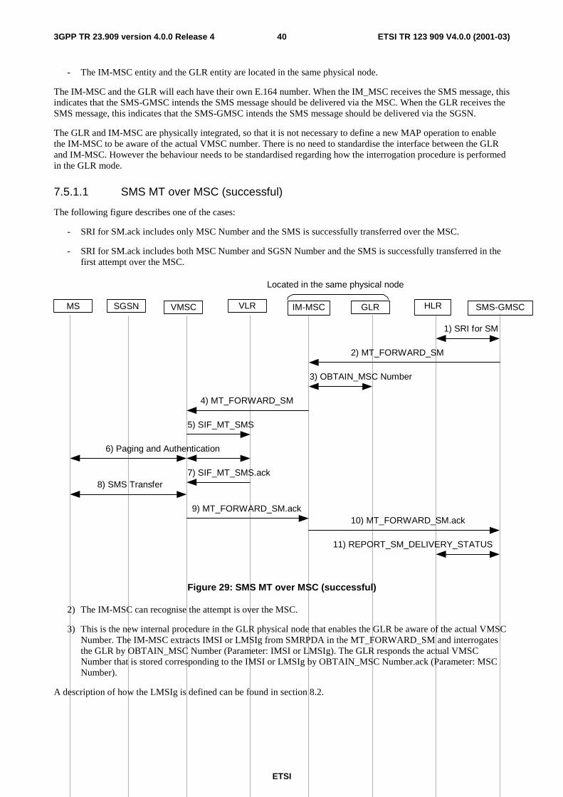
ETSI
ETSI TR 123 909 V4.0.0 (2001-03) 403GPP TR 23.909 version 4.0.0 Release 4
- The IM-MSC entity and the GLR entity are located in the same physical node.
The IM-MSC and the GLR will each have their own E.164 number. When the IM_MSC receives the SMS message, this indicates that the SMS-GMSC intends the SMS message should be delivered via the MSC. When the GLR receives the SMS message, this indicates that the SMS-GMSC intends the SMS message should be delivered via the SGSN.
The GLR and IM-MSC are physically integrated, so that it is not necessary to define a new MAP operation to enable the IM-MSC to be aware of the actual VMSC number. There is no need to standardise the interface between the GLR and IM-MSC. However the behaviour needs to be standardised regarding how the interrogation procedure is performed in the GLR mode.
7.5.1.1 SMS MT over MSC (successful)
The following figure describes one of the cases:
- SRI for SM.ack includes only MSC Number and the SMS is successfully transferred over the MSC.
- SRI for SM.ack includes both MSC Number and SGSN Number and the SMS is successfully transferred in the first attempt over the MSC.
1) SRI for SM
MS VMSC IM-MSC GLR SMS-GMSCHLRVLR
2) MT_FORWARD_SM
3) OBTAIN_MSC Number
4) MT_FORWARD_SM
5) SIF_MT_SMS
9) MT_FORWARD_SM.ack10) MT_FORWARD_SM.ack
11) REPORT_SM_DELIVERY_STATUS
Located in the same physical node
SGSN
7) SIF_MT_SMS.ack
6) Paging and Authentication
8) SMS Transfer
Figure 29: SMS MT over MSC (successful)
2) The IM-MSC can recognise the attempt is over the MSC.
3) This is the new internal procedure in the GLR physical node that enables the GLR be aware of the actual VMSC Number. The IM-MSC extracts IMSI or LMSIg from SMRPDA in the MT_FORWARD_SM and interrogates the GLR by OBTAIN_MSC Number (Parameter: IMSI or LMSIg). The GLR responds the actual VMSC Number that is stored corresponding to the IMSI or LMSIg by OBTAIN_MSC Number.ack (Parameter: MSC Number).
A description of how the LMSIg is defined can be found in section 8.2.

ETSI
ETSI TR 123 909 V4.0.0 (2001-03) 413GPP TR 23.909 version 4.0.0 Release 4
7.5.1.2 SMS MT over SGSN (successful)
The following figure describes one of the cases:
- SRI for SM.ack includes only SGSN Number and the SMS is successfully transferred over the SGSN.
- SRI for SM.ack includes both MSC Number and SGSN Number and the SMS is successfully transferred in the first attempt over the SGSN.
1) SRI for SM
MS VMSC IM-MSC GLR SMS-GMSCHLRVLR
2) MT_FORWARD_SM3) MT_FORWARD_SM
6) MT_FORWARD_SM.ack7) MT_FORWARD_SM.ack
8) REPORT_SM_DELIVERY_STATUS
Located in the same physical node
SGSN
4) Paging and Authentication
5) SMS Transfer
Figure 30: SMS MT over SGSN (successful)
2) The GLR can recognise the attempt is over the SGSN. The GLR obtains the actual SGSN Number by the IMSI in MT_FORWARD_SMS.
7.5.1.3 SMS MT over both MSC and SGSN (attempt over MSC successes)
The following figure describes the case:
- SRI for SM.ack includes both SGSN Number and MSC Number and the SMS is successfully transferred over the MSC as the second attempt.

ETSI
ETSI TR 123 909 V4.0.0 (2001-03) 423GPP TR 23.909 version 4.0.0 Release 4
1) SRI for SM
MS VMSC IM-MSC GLR SMS-GMSCHLRVLR
2) MT_FORWARD_SM3) MT_FORWARD_SM
5) MT_FORWARD_SM.ack
6) MT_FORWARD_SM.ack
16) REPORT_SM_DELIVERY_STATUS
Located in the same physical node
SGSN
4) MS detached for GPRS or No Paging Response
MNRG
MNRG
7) MT_FORWARD_SM
8) OBTAIN_MSC Number9) MT_FORWARD_SM
14) MT_FORWARD_SM.ack
11) Paging and Authentication
10) SIF_MT_SMS
12) SIF_MT_SMS.ack13) SMS Transfer
15) MT_FORWARD_SM.ack
Figure 31: SMS MT over MSC and SGSN
5) The SGSN shall return the response including “Absent Subscriber” to the GLR. The GLR sets MNRG for the MS.
8) This is the same as 3) in figure 29, shown in section 7.5.1.1.
As the SMS is transferred successfully in this case, MNRG in the SGSN may send useless READY_FOR_SM to the HLR. But this scheme ensures to initiate the SMS Alert procedure in the case only the single attempt over the SGSN is performed by the SMS-GMSC. That is specified in the current GSM/GPRS specification (03.40/03.60).
The MNRG in the GLR may cause useless SMS Alert procedure. This is the GLR specific redundancy but that is negligible as well as SGSN case.
7.5.1.4 SMS MT over both MSC and SGSN (both attempts fail)
The following figure describes the case:
- SRI for SM.ack includes both SGSN Number and MSC Number and the transfer of the SMS fails over both path.

ETSI
ETSI TR 123 909 V4.0.0 (2001-03) 433GPP TR 23.909 version 4.0.0 Release 4
1) SRI for SM
MS VMSC IM-MSC GLR SMS-GMSCHLRVLR
2) MT_FORWARD_SM3) MT_FORWARD_SM
5) MT_FORWARD_SM.ack
6) MT_FORWARD_SM.ack
15) REPORT_SM_DERIVERY_STATUS
Located in the same physical node
SGSN
4) MS detached for GPRS or No Paging Response
16) REPORT_SM_DERIVERY_STATUS.ack
MNRG
MNRG
7) MT_FORWARD_SM
8) OBTAIN_MSC Number9) MT_FORWARD_SM
11) MT_FORWARD_SM.ack
10) MS Detached for non-GPRS or Paging No Response
14) MT_FORWARD_SM.ack
MNRF
MNRF
MNRFMNRG
12) INFORM_SM_DELIVERY_FAILURE
13) INFORM_SM_DELIVERY_FAILURE.ack
Figure 32: unsuccessful SMS MT over MSC and SGSN
8) This is the same as 3) in figure 29, shown in section 7.5.1.1.
12) This is new internal procedure in the GLR physical node. The IM-MSC informs to the GLR that the delivery has been unsuccessful by INFORM_SM_DELIVERY_FAILURE (Parameter: IMSI). The GLR sets MNRF corresponding to the IMSI.

ETSI
ETSI TR 123 909 V4.0.0 (2001-03) 443GPP TR 23.909 version 4.0.0 Release 4
7.5.2 SMS Alert Procedure initiated by Update Location or Update GPRS Location
SMS Alert procedure may be initiated by various reasons. In the network with GLR, as second and further UL messages would not be reached to the HLR some consideration with which the HLR can initiate SMS Alert procedure by Update Location and Update GPRS Location should be made.
According to the procedure defined in sections 7.5.1.3 and 7.5.1.4, Update Location or Update GPRS Location can initiate SMS Alert procedure as described in the figure below. The GLR shall sends READY_FOR_SM to the HLR when and only when it has MNRF or MNRG.
Note that using READY_FOR_SM between the GLR and the HLR rather than original location registration message avoids useless ISD operation.
MS VMSC IM-MSC GLR SMS-GMSCHLRVLR
UPDATE_GPRS_LOCATION
Located in the same physical node
SGSN
MNRG
READY_FOR_SM
MNRG
ALERT_SC
RA Update
MNRF MNRF
ALERT_SC
READY_FOR_SM
UPDATE_LOCATION
UPDATE_LOCATION_AREA
LA Update
Figure 33: SMS Alert procedure initiated by HLR receiving Update Location or Update GPRS Location
7.5.3 Alternatives for SMS Support Without the IM-MSC entity
This chapter studies the necessity of defining a new entity (i.e. the IM-MSC) by analysing the SMS MT procedure over both MSC and SGSN. Two alternative approaches are described:
In the case the IM-MSC entity is not defined;
- The functionality of the IM-MSC entity is unified in the GLR entity.
- MSC Number value is GLR Number in the address conversion scheme in the GLR.
- The GLR can NOT know over which path the SMS-GMSC intends to forward the SMS the first or the second.
- The GLR needs to refer to the NAM of the subscriber in order to select the path over which the SMS is transferred. The turn to forward the SMS is up to the GLR network operator. Because MT_FORWARD_SM operation has no IE in it which indicates the path over which the SMS should be transferred.

ETSI
ETSI TR 123 909 V4.0.0 (2001-03) 453GPP TR 23.909 version 4.0.0 Release 4
Thus, the solution without the IM-MSC entity is more complex for the GLR .Introducing the IM-MSC is more compatible with the existing GSM/GPRS specifications.
7.5.3.1 Alternative 1
In the case the NAM indicates the possibility of the both path, the GLR shall perform twice attempts per one MT_FORWARD_SM.
In the case the SMS can not be transferred over the first path and can be successfully transferred over the second path, this solution shall reduce the signalling between the SMS-GMSC and the VPLMN.
But, in the case the SMS can be transferred over neither path, this solution cause useless re-attempt between the SMS-GMSC and the VPLMN, in that case, 4 attempts would be occurred.
7.5.3.2 Alternative 2
Regardless of the NAM, the GLR would perform only one attempt per one MT_FORWARD_SM.
The turn to forward the SMS is up to the GLR network operator.
The GLR should have the context in its state machine that the attempt is either the first or the second. That is very difficult or anyway makes the GLR more and more complex.
7.6 Subscriber and Equipment Trace GSM 09.02 states that subscriber and equipment trace is only available for subscribers within their HPLMN area. If the HLR receives a trace request for a subscriber, and the HLR detects that the subscriber is not in the HPLMN, then the HLR does not forward the trace request to the VPLMN. The trace request never reaches the GLR. Therefore it is concluded that the GLR has no impact on subscriber and equipment trace.
7.7 Impact of GLR on CAMEL The VLR supports CAMEL Phase 2 onwards
When the GLR receives the MAP_UPDATE_LOCATION request message from the subscriber, the GLR checks that the CAMEL supported phase it previously received for that subscriber matches the CAMEL supported phase carried by MAP_UPDATE_LOCATION request message. If a difference is detected, the GLR relays the MAP_UPDATE_LOCATION request message to the HLR in order to obtain the proper CAMEL subscription information that corresponds to the current VLR. Refer to figure 34.
In order to perform this scenario, the CAMEL supported phase information needs to be added to the ‘IMSI record in GLR’ table.
It is possible that all the VLRs within a VPLMN do not support the same phase of CAMEL. This could happen in the case of an incremental upgrade of these VLRs within the VPLMN. In this case, it is possible that the HLR may receive frequent changes of the CAMEL supported phase information in the MAP_UPDATE_LOCATION request message from the GLR. The effect is that the HLR would perceive the GLR as a VLR that changes its CAMEL supported phase.

ETSI
ETSI TR 123 909 V4.0.0 (2001-03) 463GPP TR 23.909 version 4.0.0 Release 4
MS VLR GLR HLR
A_LU_reMAP UL
MAP UL
Compare the CAMEL Supportedphase between that held in theGLR and newly received in theMAP_LU. If difference isdetected, relay MAP_UL to HLR.
MAP ISDCAMEL sub. Info.
MAP ISD ACKMAP ISD ACK
MAP UL ACKMAP UL ACK
A LUconf
GLR number
VLR number
MAP ISDCAMEL sub. Info.
Store the received CAMELSupported phase informationin GLR
Figure 34: CAMEL Subscription Information
The VLR supports CAMEL Phase 1 or has no CAMEL Support
If the Location Update Request message received by the GLR contains no indication that the VLR supports CAMEL, then this shows to the GLR that the VLR:
- either has no support for CAMEL.
- or supports CAMEL Phase 1.
The GLR will interpret this situation to mean that there is no CAMEL support within the VLR. Therefore the GLR will treat this as a case of an unsupported service (see section 7.2.1.5). This will lead to an update location procedure being initiated between the GLR and HLR, causing the HLR to activate its service substitution rules.
Note the following description of a current GSM network, i.e. where there is no GLR between the HLR and VLR. When the HLR receives a Location Update request with no indication of CAMEL support, then the HLR will attempt to request CAMEL Phase 1 support in the ISD message. If the ISD is accepted by the VLR, then support for CAMEL Phase 1 is indicated. If the ISD is rejected, then no support for CAMEL Phase 1 is indicated.
7.8 Interaction With CCBS In CCBS, certain service logic is initiated by receiving Location Update request. Therefore, CCBS is categorised as type c in 7.2.3.3.
When a subscriber is monitored (either as being a target or being the initiator of CCBS request), and roams to visited network which contains the GLR, the GLR manages monitoring state of subscriber A.
If monitoring is ongoing when the GLR receives a Location Update request from the new VLR, the GLR can take one of the following actions:
- Relay the Location Update request to the HLR to inform the appropriate CCBS processes in the HLR, or

ETSI
ETSI TR 123 909 V4.0.0 (2001-03) 473GPP TR 23.909 version 4.0.0 Release 4
- Send a StatusReport MAP operation, indicating “Idle” to the HLR, handle the Location Update request locally in the GLR, and start monitoring on the new VLR, by sending a SetReportingState MAP operation to the new VLR.
Should the SetReportingState response from the new VLR indicate “Not reachable” or “Not Idle”, then the GLR will send this status information in a StatusReport towards the HLR.
The first option has the advantage that the GLR monitoring functionality is straightforward, but implies unnecessary MAP LU traffic.
The second option has the advantage that MAP LU traffic is saved, but implies monitoring logic to be available in the GLR.
Both options imply that the GLR needs to keep track of subscribers being monitored.
Other CCBS related MAP operations, e.g. RegisterCC-entry, EraseCC-Entry, RemoteUserFree and StatusReport, are relayed transparently from the HLR to the VLR or vice versa.
7.9 Location Service (LCS) Specifications for GSM Location Services (LCS) are scheduled for approval at SMG #28. In LCS, the GMLC directly accesses the serving MSC, by first interrogating the HLR for the serving MSC Number. Therefore LCS makes use of message delivery type b in 7.2.3.2.
Figure 35 illustrates the sequence flow of MT-LR (Mobile Terminated Location Request). The sequence flow of MT-LR for a previously obtained location estimate is same as MT-LR.
GLR HLR
3. Provide Subscriber Location4. ServingMSC
Address Request
5. ServingMSCAddress Request ack
Visited NW Home NW
GMLC
1. Send Routing Infofor LCS
IMSCMSC
2. Send Routing Infofor LCS ack
6. Provide Subscriber Location
Figure 35: Mobile terminating Location Request Subscriber Information
8 Mobile terminating Location Request Subscriber Information
The subscriber information stored in the GLR can be categorised into following types.

ETSI
ETSI TR 123 909 V4.0.0 (2001-03) 483GPP TR 23.909 version 4.0.0 Release 4
8.1 Information for HLR emulation The GLR retrieves this kind of subscriber information mainly from Insert Subscriber Data message received from the HLR and stores it. Then this message is transported to the VLR transparently.
This type of information is for example:
- IMSI.
- International MS ISDN number.
- PDP Type.
8.2 Information for address and identity conversion a) Address Conversion.
On location updating the VLR or SGSN sends Update Location message to the GLR and notifies its VLR number and MSC number or SGSN number and SGSN address by the message. On the first updating in the newly visited network, the GLR relays Update Location message to the HLR setting.
- The GLR number as the VLR number(E.164 address).
- The IMSC number as the MSC number(E.164 address).
- The GLR number as the SGSN number(E.164 address).
- The IM-GSN address as the SGSN address(IP address).
The GLR keeps the association of these numbers and addresses and updates it on the second and further updating. And when the GLR receives and stores the HLR number in Update Location ack message form the HLR, it relays the message to the VLR setting.
- The GLR number as the HLR number (E. 164 address).
b) Identity Conversion.
On location updating the VLR creates and allocates the LMSI number(denote LMSIv) for the user and sends it to the GLR in Update Location message. When the GLR receives the message, it creates and allocates another LMSI number(denote LMSIg) and associates LMSIg with received LMSIv. The GLR notifies LMSIg to the HLR sending Update Location message. This method can speed up the search for subscriber data in the GLR when the GLR receives some message from the HLR.
8.3 Information for Location updating Screening This information is used for the GLR to judge whether requested location updating is necessary to be indicated to HLR or not. Following are information categorized in this type.
- MNRF, MNRG.
- CCBS Monitoring Flag (provisional name).
- MSC area restricted flag.
- SGSN area restricted flag.
Section 7.5 shows the procedure for SMS alerting in the network with the GLR. In the procedure Mobile station Not Reachable Flag (MNRF) and Mobile station Not Reachable for GPRS(MNRG) are needed.
The CCBS Monitoring Flag is set when the user in the GLR area is CCBS monitored by the VLR. While it is set, the Update Location message is relayed to the HLR to inform the appropriate CCBS process in the HLR. More detailed procedures for the CCBS are included in section 7.8.

ETSI
ETSI TR 123 909 V4.0.0 (2001-03) 493GPP TR 23.909 version 4.0.0 Release 4
MSC area restricted flag and SGSN area restricted flag are needed for regional restriction service. See section 7.2.1.4 for more detailed procedures.
8.4 Other Information The GLR has Service Substitution Induced Flag list. This information show which service is replaced by service substitution. See section 7.2.1.5 for more detail on the handling of unsupported services.

ETSI
ETSI TR 123 909 V4.0.0 (2001-03) 503GPP TR 23.909 version 4.0.0 Release 4
8.5 IMSI Record in GLR
Table 1: Subscriber Information stored in the GLR
PARAMETER PRESENCE CATEGORY (*1) NOTE IMSI M A
Network Access Mode C A
International MS ISDN number M A
LMSI C B
Mobile Station Category M A
VLR number M B
MSC number M B
HLR number C B
Zone Code List C A
Roaming restriction due to unsupported feature C A
MSC area restricted flag M C
LSA Identity C A
LSA Priority C A
LSA Only Access Indicator C A
LSA Active Mode Indicator C A
Provision of bearer service M A
Provision of teleservice M A
BC allocation C A
Subscriber status C A
Barring of outgoing calls C A
Barring of premium rate calls C A
Barring of supplementary service management C A
Barring of invocation of call transfer C A
Mobile Station Not Reachable Flag M C
VGCS Group Membership List C A
VBS Group Membership List C A
Broadcast Call Initiation Allowed List C A

ETSI
ETSI TR 123 909 V4.0.0 (2001-03) 513GPP TR 23.909 version 4.0.0 Release 4
PARAMETER PRESENCE CATEGORY (*1) NOTE Originating CAMEL Subscription Information C A
SS invocation notification (SS-CSI) C A
CCBS Monitoring Flag C C
Location and Subscriber information Confirmed by HLR indicator
M C
CAMEL Supported phases information C C
Service Substitution Induced Flag list C D
Forwarding information List C A
Call barring information List C A
CUG information List C A
SS-Data List C A
EMLPP Subscription C A
North American Equal Access preferred Carrier Id List C A
Packet Specific Data SGSN number M B
Roaming Restriction in the SGSN due to unsupported feature
M A
SGSN area restricted flag M C
MNRG M C
PDP Type C A
PDP Address C A
SGSN address M B
Access Point Name C A
VPLMN Address Allowed C A
Quality of Service Subscribed C A
(*1) A: Information for HLR emulation.
B: Information for address and identity conversion.
C: Information for Location updating Screening.
D: Others.
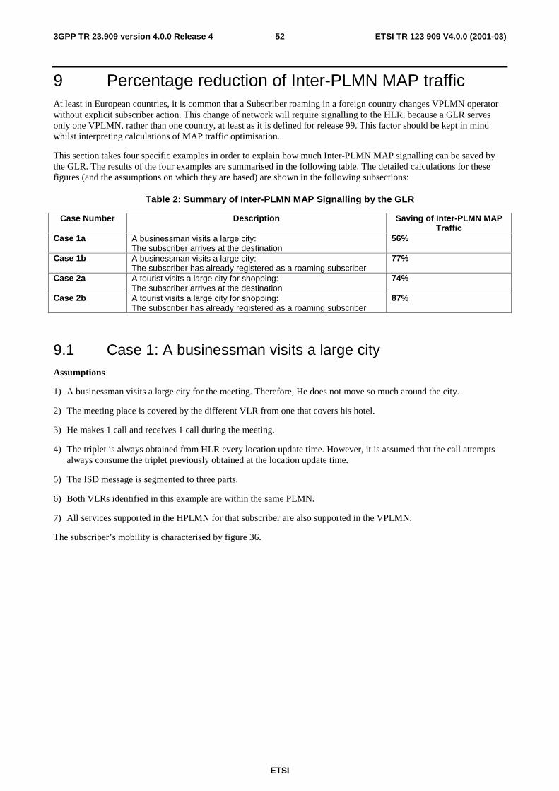
ETSI
ETSI TR 123 909 V4.0.0 (2001-03) 523GPP TR 23.909 version 4.0.0 Release 4
9 Percentage reduction of Inter-PLMN MAP traffic At least in European countries, it is common that a Subscriber roaming in a foreign country changes VPLMN operator without explicit subscriber action. This change of network will require signalling to the HLR, because a GLR serves only one VPLMN, rather than one country, at least as it is defined for release 99. This factor should be kept in mind whilst interpreting calculations of MAP traffic optimisation.
This section takes four specific examples in order to explain how much Inter-PLMN MAP signalling can be saved by the GLR. The results of the four examples are summarised in the following table. The detailed calculations for these figures (and the assumptions on which they are based) are shown in the following subsections:
Table 2: Summary of Inter-PLMN MAP Signalling by the GLR
Case Number Description Saving of Inter-PLMN MAP Traffic
Case 1a A businessman visits a large city: The subscriber arrives at the destination
56%
Case 1b A businessman visits a large city: The subscriber has already registered as a roaming subscriber
77%
Case 2a A tourist visits a large city for shopping: The subscriber arrives at the destination
74%
Case 2b A tourist visits a large city for shopping: The subscriber has already registered as a roaming subscriber
87%
9.1 Case 1: A businessman visits a large city Assumptions
1) A businessman visits a large city for the meeting. Therefore, He does not move so much around the city.
2) The meeting place is covered by the different VLR from one that covers his hotel.
3) He makes 1 call and receives 1 call during the meeting.
4) The triplet is always obtained from HLR every location update time. However, it is assumed that the call attempts always consume the triplet previously obtained at the location update time.
5) The ISD message is segmented to three parts.
6) Both VLRs identified in this example are within the same PLMN.
7) All services supported in the HPLMN for that subscriber are also supported in the VPLMN.
The subscriber’s mobility is characterised by figure 36.

ETSI
ETSI TR 123 909 V4.0.0 (2001-03) 533GPP TR 23.909 version 4.0.0 Release 4
Hotel
Meetingplace
Go to the meeting in the morning.
Return in the evening.
Receive 1 calland originate1 call.
VLR-1 VLR-2He roams to VLR-1 for business trip.
Figure 36: A Business Subscriber Visits a Large City
9.1.1 Case 1a: The subscriber arrives at the destination
On day one, the subscriber arrives at the destination and registers as a roaming subscriber in the VPLMN.
- The number of MAP signals between VLR and HLR (without GLR).
3 UL: The first arrival to the hotel in VLR-1, in VLR-2, in VLR-1 when he returns.
3 * (3 * ISD).
3 * SAI.
2 CL: One for VLR-1 when he moves to VLR-2, one for VLR-2 when he returns.
1 PRN: Due to the terminating call to him.
Total: 18 MAP messages
- The number of MAP signals between GLR and HLR (with GLR).
1 UL: The first arrival to the hotel in VLR-1.
1 * (3 * ISD).
3 * SAI.
1 PRN: Due to the terminating call to him.
Total: 8 MAP messages
- Percentage reduction of MAP traffic signalling.
100% - (8/18)*100% = 56%.
56% of Inter-PLMN MAP messages can be saved.
NOTE: If VLR 1 and VLR 2 are in different VPLMNs, no reduction in Inter-PLMN traffic is achieved.

ETSI
ETSI TR 123 909 V4.0.0 (2001-03) 543GPP TR 23.909 version 4.0.0 Release 4
9.1.2 Case 1b:The subscriber has already registered as a roaming subscriber
On day two (and all subsequent days) the subscriber no longer needs to register as a roaming subscriber in the VPLMN.
- The number of MAP signals between VLR and HLR (without GLR).
2 UL: Arrival in VLR-2 and in VLR-1 when he returns.
2 * (3 * ISD).
2 * SAI.
2 CL: One for VLR-1 when he moves to VLR-2, one for VLR-2 when he returns.
1 PRN: Due to the terminating call to him.
Total: 13 MAP messages
- The number of MAP signals between GLR and HLR (with GLR).
2 * SAI.
1 PRN: Due to the terminating call to him.
Total: 3 MAP messages
- Percentage reduction of MAP traffic signalling.
100% - (3/13)*100% = 77%.
77% of Inter-PLMN MAP messages can be saved.
NOTE: If VLR 1 and VLR 2 are in different VPLMNs, no reduction in Inter-PLMN traffic is achieved.
9.2 Case 2: A tourist visits a large city for shopping Assumptions
1) A tourist visits a large city for shopping. He frequently uses the train to move around the city.
2) The area he moves is divided into four VLRs.
3) He makes 1 call and receives 1 call during the shopping.
4) The number of triplet for SAI is four.
5) The ISD message is segmented to three parts.
6) All VLRs identified in this example are within the same PLMN.
7) All services supported in the HPLMN for that subscriber are also supported in the VPLMN.
The subscriber’s mobility is characterised by figure 37.

ETSI
ETSI TR 123 909 V4.0.0 (2001-03) 553GPP TR 23.909 version 4.0.0 Release 4
Hotel
DepartmentAMoved by train
VLR-1 VLR-2
RestartA
DepartmentB Moved by train
VLR-3VLR-4
Receive 1call andoriginate 1call
Figure 37: Tourist Visiting a large City
9.2.1 Case 2a: The subscriber arrives at the destination
On day one, the subscriber arrives at the destination and registers as a roaming subscriber in the VPLMN.
- The number of MAP signals between VLR and HLR (without GLR).
5 UL: The first arrival in VLR-1, in VLR-2, in VLR-3, in VLR-4 and in VLR-1 when she returns.
5* (3 * ISD).
2 * SAI: He consumes 6 triplets so that he needs to send SAI twice.
4 CL: in VLR-2, in VLR-3, in VLR-4 and in VLR-1 when she returns.
1 PRN: Due to the terminating call to him.
Total: 27 MAP messages
- The number of MAP signals between GLR and HLR (with GLR).
1 UL: The first arrival to the hotel in VLR-1.
1 * (3 * ISD).
2 * SAI.
1 PRN: Due to the terminating call to him.
Total: 7 MAP messages.
- Percentage reduction of MAP traffic signalling.
100% - (7/27)*100% = 74%.
74% of Inter-PLMN MAP message can be saved.
NOTE: If the subscriber roams to different VPLMNs at every stage in this example, no reduction in Inter-PLMN traffic is achieved.
9.2.2 Case 2b: The subscriber has already registered as a roaming subscriber
On day two (and all subsequent days) the subscriber no longer needs to register as a roaming subscriber in the VPLMN.

ETSI
ETSI TR 123 909 V4.0.0 (2001-03) 563GPP TR 23.909 version 4.0.0 Release 4
- The number of MAP signals between VLR and HLR (without GLR).
4 UL: in VLR-2, in VLR-3, in VLR-4 and in VLR-1 when she returns.
4 * (3 * ISD).
2 * SAI: He consumes 6 triplets so that he needs to send SAI twice.
4 CL: in VLR-2, in VLR-3, in VLR-4 and in VLR-1 when she returns.
1 PRN: Due to the terminating call to him.
Total: 23 MAP messages.
- The number of MAP signals between GLR and HLR (with GLR).
2 * SAI.
1 PRN: Due to the terminating call to him.
Total: 3 MAP messages.
- Percentage reduction of MAP traffic signalling.
100% - (3/23)*100% = 87%.
87% of Inter PLMN MAP messages can be saved.
NOTE: If the subscriber roams to different VPLMNs at every stage in this example, no reduction in Inter-PLMN traffic is achieved.
9.3 Location Update An alternative method of calculating the reduction in signalling traffic is given in this section.
The sequence flow diagram of Location Update between different VLR service areas in the visited network is shown in figure 38. The case that the network does not contain the GLR is shown in part *a, and the case that the network contains the GLR is shown in part *b.
Introducing GLR at visited network, 6 messages, Update Location, Cancel Location, Insert Subscriber Data and their acknowledgements, are reduced at inter-network per one Location Update.
Using following parameters, amount of traffic of inter-network signalling related to update location can represent xyz*8/3600(bps).
x: average number of location updates for each roaming subscriber per one hour.
y: average number of roaming subscribers.
z (bytes): average amount of bytes within the 6 messages of one location update.
Example values of these parameters are as follows:
x = 1.25 (LU in one hour per roaming subscriber).
y = 100000(roaming subscribers).
z = 1000(bytes per LU sequence).
In this case, the amount of reduction of inter-network signalling by introduction of GLR is about 278kbps.

ETSI
ETSI TR 123 909 V4.0.0 (2001-03) 573GPP TR 23.909 version 4.0.0 Release 4
HLR
1. Update Location
1. Update Location
3. Insert SubscriberData
3. Insert Subscriber Data
3. Insert Subscriber Data ack
3. Insert SubscriberData ack
1. Update Location ack
1. Update Location ack
Visited NW Home NW
VLRNEWVLROLD
2. Cancel Location
2. Cancel Location ack
GLR
2. Cancel Location
2. Cancel Location ack
*a
*b
*a GLR is not introduced*b GLR is introduced
Figure 38: Location Update Procedure with/without GLR
10 Interworking with existing GSM networks One of the requirements of the present document is to describe a network architecture where the presence of a GLR within a UMTS PLMN is not visible to either a second generation PLMN (i.e. GSM release 98 or earlier) or a 3G PLMN (i.e. GSM Release 99 or later). In other words, the GLR will not require changes to the GSM specifications, in order to interwork with other GSM PLMNs.
11 Impact on GSM Release 99 Specifications Introduction of the GLR will not change any GSM Interfaces, so from the interface point of view there will be no impact of the GLR on the GSM Specifications. However, GSM specifications will need to change in order to standardise the behaviour of the GLR. The affected specifications will include:
GSM 09.02 MAP.
GSM 09.60 GPRS.
GSM 03.40 SMS.

ETSI
ETSI TR 123 909 V4.0.0 (2001-03) 583GPP TR 23.909 version 4.0.0 Release 4
GSM 03.60 GPRS.
GSM 03.07 Restart.
GSM 03.08 Subscriber Profile.
GSM 03.93 CCBS.
GSM 03.18.
Further study is needed to determine if any other GSM 03.xx specifications need to be modified.
12 Advantages of the GLR
12.1 Optimisation of MAP Traffic The GLR reduces the amount of mobility related MAP signalling between PLMNs. This will be a significant benefit to UMTS for the following reasons:
IMT-2000 networks based on GSM evolution are planned for Europe, Japan, USA and Korea. Coupled with steadily increasing rates of international travel for business and leisure, this means a significant increase in the number of roaming users needing to be supported. This will lead to increased signalling traffic on "short -haul" and "long-haul" international links.
Consequently, UMTS network operators are likely to face increased charges for international signalling traffic as demand for UMTS service increases. The GLR offers UMTS network operators the chance to minimise the rate at which these signalling traffic charges increase.
Furthermore, HPLMNs will benefit from the reduction in MAP signalling due to roaming subscribers, because of the reduced processing load on the HLR.
12.2 Interworking With GSM The GLR concept can be introduced into a PLMN without requiring a functional change or upgrade to the other PLMN nodes.
13 Drawbacks of the GLR
13.1 Application level analysis of signalling The GLR has to analyse MAP messages from the VLR to determine whether they should be:
- Passed on without modification to the HLR;
- Modified (e.g. by replacing the VLR address at the application level with the GLR address) before being passed on to the HLR;
- Handled at the application level in the GLR, without being passed on to the HLR.
The GLR therefore has to terminate all TC dialogues with the VLRs which it serves, and initiate a new TC dialogue with the appropriate HLR for the cases in the first two bullets above. This treatment adds to the time taken to process those messages which have to be passed to the HLR.

ETSI
ETSI TR 123 909 V4.0.0 (2001-03) 593GPP TR 23.909 version 4.0.0 Release 4
13.2 Reliability Issues
13.2.1 Reliability requirements
The GLR handles all the signalling traffic to the HPLMN for roaming subscribers, and has to maintain the subscriber database for roaming subscribers. This imposes a high reliability requirement (at least as high as for the HLR) on the GLR, because it is a single point of failure for all the visitors from a given HPLMN.
13.2.2 Effect on overall system reliability
The addition of a new node (the GLR) to the signalling path between the VLR and the HLR introduces an additional point of failure. The effect of this on the overall system reliability needs to be considered. Similarly, the impact of the GLR restoration processing and signalling needs to be studied.
13.3 Upgrading of GLR capabilities The GLR acts as a VLR when interworking with an HLR, and as an HLR when interworking with a VLR. In order to avoid the GLR imposing the limit on the service capabilities of the VPLMN, the GLR has to support the highest capability level, as seen by the HLR, of all the VLRs which it serves. Hence whenever the capability of a served VLR is increased the capability of the GLR has to be increased to match. Similarly, it could be argued that whenever the capability of the HLR as seen by the VLR is increased the capability of the GLR has to be increased to match.
13.4 Handling of unsupported services When an MS registers in a new VLR, the subscriber data management procedure allows the VLR to indicate towards the HLR the services which are provisioned for the subscriber but which the VLR does not support. It is essential that the HLR is aware of which services are not supported, so that it can decide what action to take for the subscriber. In order to handle different levels of support of services in different VLRs served by the same GLR, there is a trade-off between additional signalling towards the HLR to make the HLR aware of the level of support in each VLR, and additional complexity in the GLR to reduce the signalling towards the HLR.
13.5 VLR Location Based Services In current HLRs there can be operator specific services based on the VLR service area where the Subscriber is currently roaming. The resolution of location information is changed from the granularity of a VLR region to a GLR area (i.e. a whole PLMN).
14 Open Issues
14.1 Additional signalling load on HLR restart When any HLR node served by a GLR restarts, the Reset message from that HLR will trigger an Update Location dialogue for every subscriber served by that GLR. This will lead to large peaks in signalling. If the GLR were not used then Update Location dialogues would be triggered only for those subscribers served by the HLR node which restarted, and the signalling load would be lower. A possible solution to this problem is to use a distinct global title for the GLR to correspond to each HLR node which the GLR serves, but further study is needed to find how to reduce the signalling load on HLR restart.

ETSI
ETSI TR 123 909 V4.0.0 (2001-03) 603GPP TR 23.909 version 4.0.0 Release 4
Annex A: Change history
Change history TSG CN# Spec Version CR <Phase> New Version Subject/Comment 04 23.909 1.0.4 R99 3.0.0 Under change control 23.909 3.0.0 R99 3.0.1 Editorial clean up (MCC) 11 23.909 3.0.1 Rel-4 4.0.0 Approved in CN#11

61
ETSI
ETSI TR 123 909 V4.0.0 (2001-03)3GPP TR 23.909 version 4.0.0 Release 4
History
Document history
V4.0.0 March 2001 Publication