Tow Steered Wing Structure Design - NASA Aeronautics ... · Tow Steered Wing Structure Design ......
18
1 Tow Steered Wing Structure Design Mike Henson University of Texas at Arlington, Arlington, TX Bo Wang University of Texas at Arlington, Arlington, TX OpenVSP Workshop 2016
Transcript of Tow Steered Wing Structure Design - NASA Aeronautics ... · Tow Steered Wing Structure Design ......

1
Tow Steered Wing Structure Design
Mike HensonUniversity of Texas at Arlington, Arlington, TX
Bo WangUniversity of Texas at Arlington, Arlington, TX
OpenVSP Workshop 2016

Outline
• Motivation and Research Goals• Background• Analytical Approach• Numerical Implementation• Current Challenges• Summary and Future Work
2
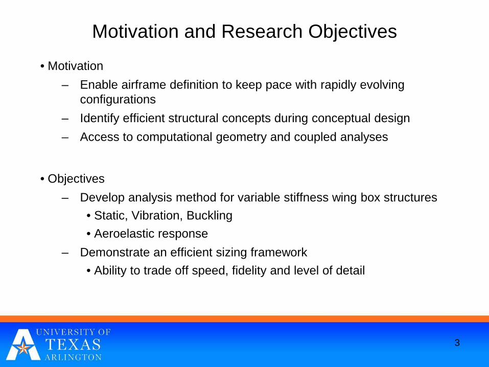
Motivation and Research Objectives
• Motivation– Enable airframe definition to keep pace with rapidly evolving
configurations– Identify efficient structural concepts during conceptual design– Access to computational geometry and coupled analyses
• Objectives– Develop analysis method for variable stiffness wing box structures
• Static, Vibration, Buckling• Aeroelastic response
– Demonstrate an efficient sizing framework• Ability to trade off speed, fidelity and level of detail
3
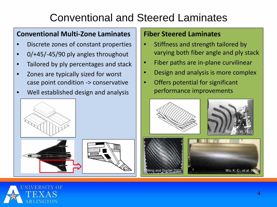
Conventional and Steered Laminates
4
Conventional Multi-Zone Laminates• Discrete zones of constant properties• 0/+45/-45/90 ply angles throughout• Tailored by ply percentages and stack• Zones are typically sized for worst
case point condition -> conservative• Well established design and analysis
Fiber Steered Laminates• Stiffness and strength tailored by
varying both fiber angle and ply stack • Fiber paths are in-plane curvilinear• Design and analysis is more complex• Offers potential for significant
performance improvements
Tatting and Gurdal 2002 Wu, K. C., et al. 2009
Blom, A. W. 2010
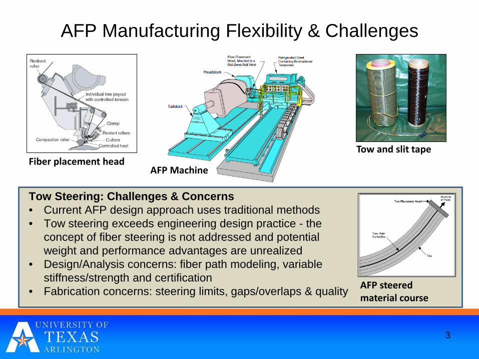
AFP Manufacturing Flexibility & Challenges
AFP steered material course
Tow and slit tapeFiber placement head
AFP Machine
Tow Steering: Challenges & Concerns• Current AFP design approach uses traditional methods• Tow steering exceeds engineering design practice - the
concept of fiber steering is not addressed and potential weight and performance advantages are unrealized
• Design/Analysis concerns: fiber path modeling, variable stiffness/strength and certification
• Fabrication concerns: steering limits, gaps/overlaps & quality
3
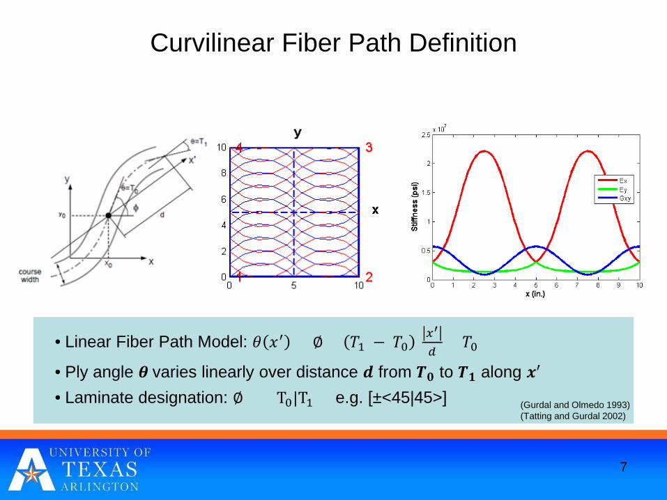
Curvilinear Fiber Path Definition
7
• Linear Fiber Path Model: 𝜃𝜃 𝑥𝑥′ = ∅ + 𝑇𝑇1 − 𝑇𝑇0𝑥𝑥′
𝑑𝑑+ 𝑇𝑇0
• Ply angle 𝜽𝜽 varies linearly over distance 𝒅𝒅 from 𝑻𝑻𝟎𝟎 to 𝑻𝑻𝟏𝟏 along 𝒙𝒙′
• Laminate designation: ∅ ±< T0|T1 > e.g. [±<45|45>] (Gurdal and Olmedo 1993)(Tatting and Gurdal 2002)
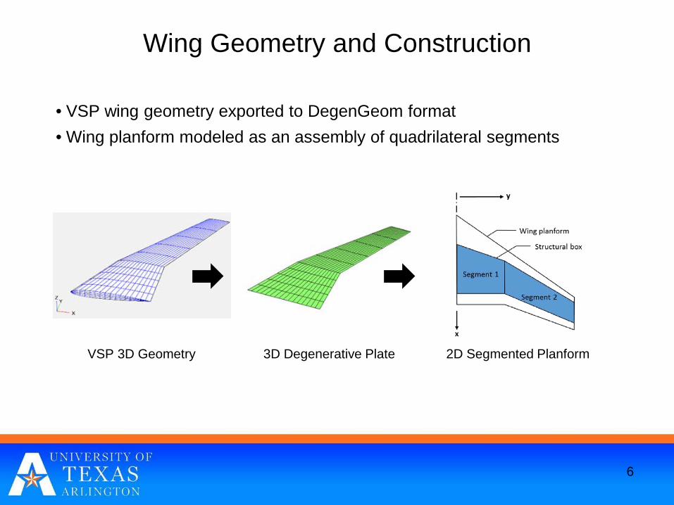
Wing Geometry and Construction
• VSP wing geometry exported to DegenGeom format• Wing planform modeled as an assembly of quadrilateral segments
6
VSP 3D Geometry 3D Degenerative Plate 2D Segmented Planform
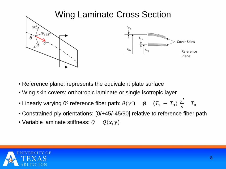
Wing Laminate Cross Section
• Reference plane: represents the equivalent plate surface• Wing skin covers: orthotropic laminate or single isotropic layer
• Linearly varying 0o reference fiber path: 𝜃𝜃 𝑦𝑦′ = ∅ + 𝑇𝑇1 − 𝑇𝑇0𝑦𝑦′
𝑠𝑠+ 𝑇𝑇0
• Constrained ply orientations: [0/+45/-45/90] relative to reference fiber path• Variable laminate stiffness: 𝑄𝑄 = 𝑄𝑄 𝑥𝑥,𝑦𝑦
8
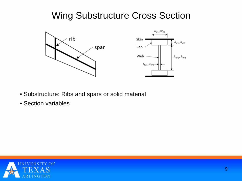
Wing Substructure Cross Section
• Substructure: Ribs and spars or solid material• Section variables
9
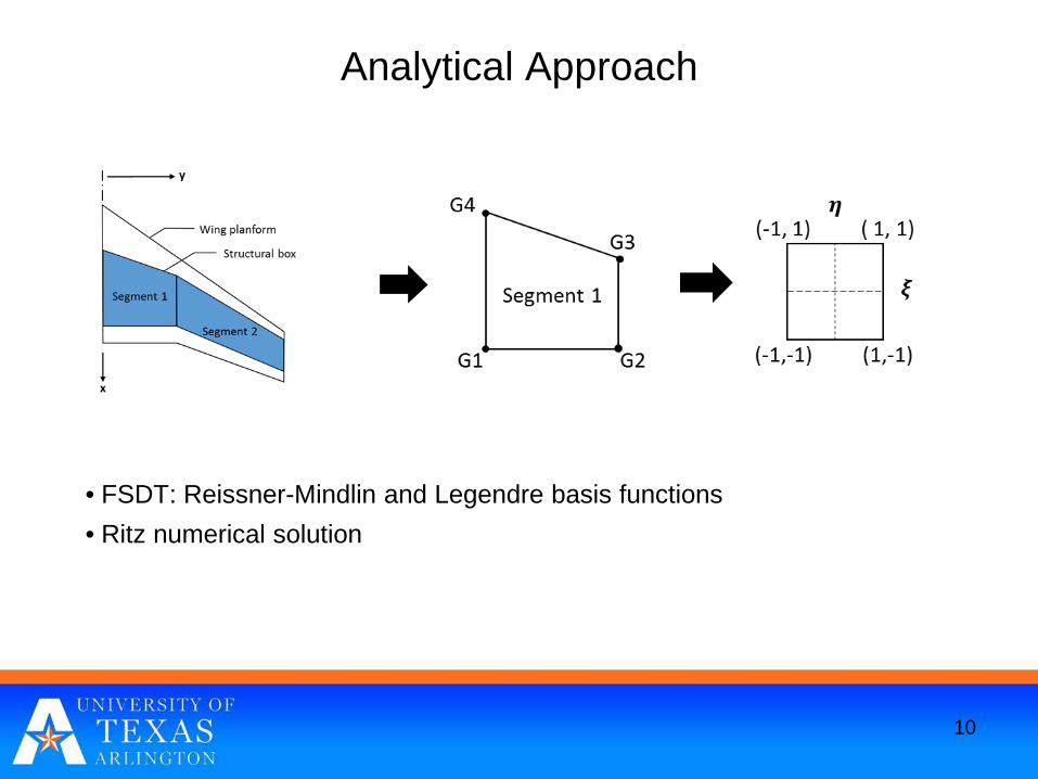
Analytical Approach
• FSDT: Reissner-Mindlin and Legendre basis functions• Ritz numerical solution
10

Buckling Panel Definitions
• Panels derived from rib-spar intersections• Ritz buckling analysis:
– Reference: AIAA 2016-1975– Good correlation with Nastran FEM
11
𝑢𝑢0 = 𝐵𝐵𝐼𝐼𝐼𝐼𝑇𝑇𝑞𝑞𝑈𝑈 = �
𝑖𝑖=1
𝐼𝐼
�𝑗𝑗=1
𝐼𝐼
𝐵𝐵𝑖𝑖𝑗𝑗 𝜉𝜉, 𝜂𝜂 𝑞𝑞𝑖𝑖𝑗𝑗 𝑡𝑡
𝑣𝑣0 = 𝐵𝐵𝐾𝐾𝐾𝐾 𝑇𝑇 𝑞𝑞𝑉𝑉 = �𝑘𝑘=1
𝐾𝐾
�𝑙𝑙=1
𝐾𝐾
𝐵𝐵𝑘𝑘𝑙𝑙 𝜉𝜉, 𝜂𝜂 𝑞𝑞𝑘𝑘𝑙𝑙 𝑡𝑡
𝑤𝑤0 = 𝐵𝐵𝑀𝑀𝑀𝑀 𝑇𝑇 𝑞𝑞𝑊𝑊 = �𝑚𝑚=1
𝑀𝑀
�𝑛𝑛=1
𝑀𝑀
𝐵𝐵𝑚𝑚𝑛𝑛 𝜉𝜉, 𝜂𝜂 𝑞𝑞𝑚𝑚𝑛𝑛 𝑡𝑡
𝜙𝜙𝑥𝑥 = 𝐵𝐵𝑃𝑃𝑃𝑃𝑇𝑇𝑞𝑞𝑋𝑋 = �
𝑝𝑝=1
𝑃𝑃
�𝑞𝑞=1
𝑃𝑃
𝐵𝐵𝑝𝑝𝑞𝑞 𝜉𝜉, 𝜂𝜂 𝑞𝑞𝑝𝑝𝑞𝑞 𝑡𝑡
𝜙𝜙𝑦𝑦 = 𝐵𝐵𝑅𝑅𝑅𝑅 𝑇𝑇 𝑞𝑞𝑌𝑌 = �𝑟𝑟=1
𝑅𝑅
�𝑠𝑠=1
𝑅𝑅
𝐵𝐵𝑟𝑟𝑠𝑠 𝜉𝜉, 𝜂𝜂 𝑞𝑞𝑟𝑟𝑠𝑠 𝑡𝑡
BilinearTransform 𝑥𝑥 𝜉𝜉, 𝜂𝜂 = �
𝑖𝑖=1
4
𝑁𝑁𝑖𝑖 𝜉𝜉, 𝜂𝜂 𝑥𝑥𝑖𝑖
𝑦𝑦 𝜉𝜉, 𝜂𝜂 = �𝑖𝑖=1
4
𝑁𝑁𝑖𝑖 𝜉𝜉, 𝜂𝜂 𝑦𝑦𝑖𝑖
𝑈𝑈 =12�𝐴𝐴
� 𝑞𝑞 𝑇𝑇 𝐶𝐶 𝑇𝑇 𝑇𝑇𝑒𝑒 𝑇𝑇 𝐷𝐷 𝑇𝑇𝑒𝑒 [𝐶𝐶] 𝑞𝑞 𝐽𝐽 𝑑𝑑𝜉𝜉𝑑𝑑𝜂𝜂
=12𝑞𝑞 𝑇𝑇 𝐾𝐾𝑐𝑐 {𝑞𝑞}
𝐾𝐾𝑐𝑐 = �𝐴𝐴
𝐶𝐶 𝑇𝑇 𝑇𝑇𝑒𝑒 𝑇𝑇 𝐷𝐷 𝑇𝑇𝑒𝑒 𝐶𝐶 𝐽𝐽 𝑑𝑑𝜉𝜉𝑑𝑑𝜂𝜂
𝐾𝐾𝑐𝑐 �= �𝑖𝑖=1
𝑀𝑀𝑔𝑔
�𝑗𝑗=1
𝑀𝑀𝑔𝑔
𝑔𝑔𝑖𝑖 𝑔𝑔𝑗𝑗𝐾𝐾𝑚𝑚𝑛𝑛 𝜉𝜉𝑖𝑖 , 𝜂𝜂𝑗𝑗
𝐾𝐾𝑚𝑚𝑛𝑛 = 𝐶𝐶 𝑇𝑇 𝑇𝑇𝑒𝑒 𝑇𝑇 𝐷𝐷 𝑇𝑇𝑒𝑒 𝐶𝐶 𝐽𝐽 (𝜉𝜉𝑖𝑖,𝜂𝜂𝑗𝑗)
𝑔𝑔𝑖𝑖,𝑔𝑔𝑗𝑗 = 𝐺𝐺𝐺𝐺𝑢𝑢𝐺𝐺𝐺𝐺 𝑤𝑤𝑤𝑤𝑤𝑤𝑔𝑔𝑤𝑡𝑡𝐺𝐺
�𝑄𝑄11 𝑥𝑥,𝑦𝑦 = 𝑈𝑈1 + 𝑈𝑈2cos 2𝜃𝜃 𝑥𝑥,𝑦𝑦 + 𝑈𝑈3cos 4𝜃𝜃 𝑥𝑥, 𝑦𝑦�𝑄𝑄12 𝑥𝑥,𝑦𝑦 = 𝑈𝑈4 − 𝑈𝑈3cos 4𝜃𝜃 𝑥𝑥, 𝑦𝑦�𝑄𝑄22 𝑥𝑥,𝑦𝑦 = 𝑈𝑈1 − 𝑈𝑈2cos 2𝜃𝜃 𝑥𝑥, 𝑦𝑦 + 𝑈𝑈3cos 4𝜃𝜃 𝑥𝑥, 𝑦𝑦�𝑄𝑄66 𝑥𝑥,𝑦𝑦 = 𝑈𝑈5 − 𝑈𝑈3cos 4𝜃𝜃 𝑥𝑥,𝑦𝑦�𝑄𝑄16 𝑥𝑥,𝑦𝑦 = − ⁄1 2𝑈𝑈2sin 2𝜃𝜃 𝑥𝑥,𝑦𝑦 − 𝑈𝑈3cos 4𝜃𝜃 𝑥𝑥,𝑦𝑦�𝑄𝑄26 𝑥𝑥,𝑦𝑦 = − ⁄1 2𝑈𝑈2sin 2𝜃𝜃 𝑥𝑥, 𝑦𝑦 + 𝑈𝑈3cos 4𝜃𝜃 𝑥𝑥, 𝑦𝑦
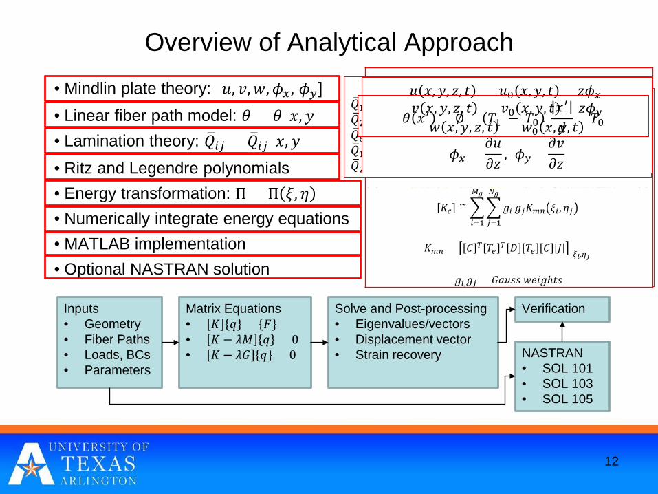
Overview of Analytical Approach
• Mindlin plate theory: [𝑢𝑢, 𝑣𝑣,𝑤𝑤,𝜙𝜙𝑥𝑥, 𝜙𝜙𝑦𝑦]• Linear fiber path model: 𝜃𝜃 = 𝜃𝜃(𝑥𝑥, 𝑦𝑦)• Lamination theory: �𝑄𝑄𝑖𝑖𝑗𝑗 = �𝑄𝑄𝑖𝑖𝑗𝑗(𝑥𝑥,𝑦𝑦)• Ritz and Legendre polynomials• Energy transformation: Π = Π 𝜉𝜉, 𝜂𝜂• Numerically integrate energy equations• MATLAB implementation• Optional NASTRAN solution
12
Inputs• Geometry• Fiber Paths• Loads, BCs• Parameters
Matrix Equations• 𝐾𝐾 𝑞𝑞 = 𝐹𝐹• 𝐾𝐾 − 𝜆𝜆𝑀𝑀 𝑞𝑞 = 0• 𝐾𝐾 − 𝜆𝜆𝐺𝐺 𝑞𝑞 = 0
Solve and Post-processing• Eigenvalues/vectors• Displacement vector• Strain recovery NASTRAN
• SOL 101• SOL 103• SOL 105
Verification
𝑢𝑢 𝑥𝑥,𝑦𝑦, 𝑧𝑧, 𝑡𝑡 = 𝑢𝑢0 𝑥𝑥,𝑦𝑦, 𝑡𝑡 + 𝑧𝑧𝜙𝜙𝑥𝑥𝑣𝑣 𝑥𝑥,𝑦𝑦, 𝑧𝑧, 𝑡𝑡 = 𝑣𝑣0 𝑥𝑥,𝑦𝑦, 𝑡𝑡 + 𝑧𝑧𝜙𝜙𝑦𝑦
𝑤𝑤 𝑥𝑥,𝑦𝑦, 𝑧𝑧, 𝑡𝑡 = 𝑤𝑤0 𝑥𝑥,𝑦𝑦, 𝑡𝑡
𝜙𝜙𝑥𝑥 =𝜕𝜕𝑢𝑢𝜕𝜕𝑧𝑧
, 𝜙𝜙𝑦𝑦=𝜕𝜕𝑣𝑣𝜕𝜕𝑧𝑧
𝜃𝜃 𝑥𝑥′ = ∅ + 𝑇𝑇1 − 𝑇𝑇0𝑥𝑥′
𝑑𝑑+ 𝑇𝑇0
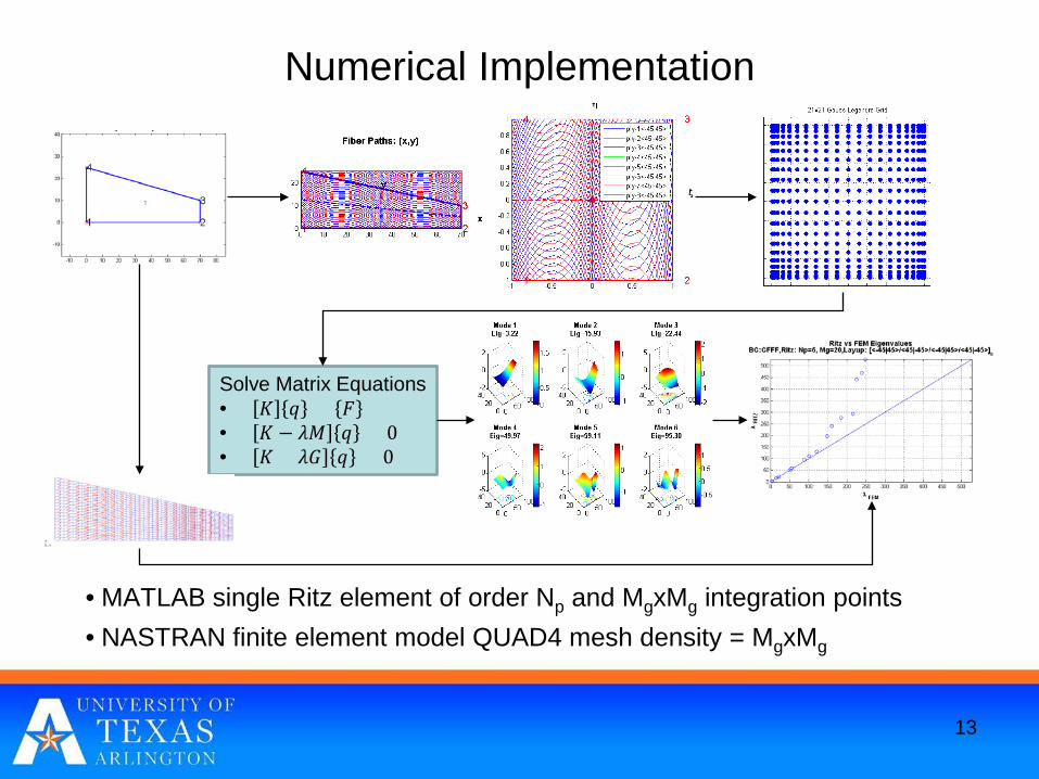
Numerical Implementation
• MATLAB single Ritz element of order Np and MgxMg integration points• NASTRAN finite element model QUAD4 mesh density = MgxMg
13
Solve Matrix Equations• 𝐾𝐾 𝑞𝑞 = 𝐹𝐹• 𝐾𝐾 − 𝜆𝜆𝑀𝑀 𝑞𝑞 = 0• 𝐾𝐾 + 𝜆𝜆𝐺𝐺 𝑞𝑞 = 0

Finite Element Solution
• Desired: Ability to create in VSP• Nastran FEM created automatically and solved in parallel• Provide calibration of Ritz solutions• Higher fidelity + ability to increase level of detail• Managing product structure (TMP/Vision-Viewsets)• Managing results (TMP/Slim DB)
14
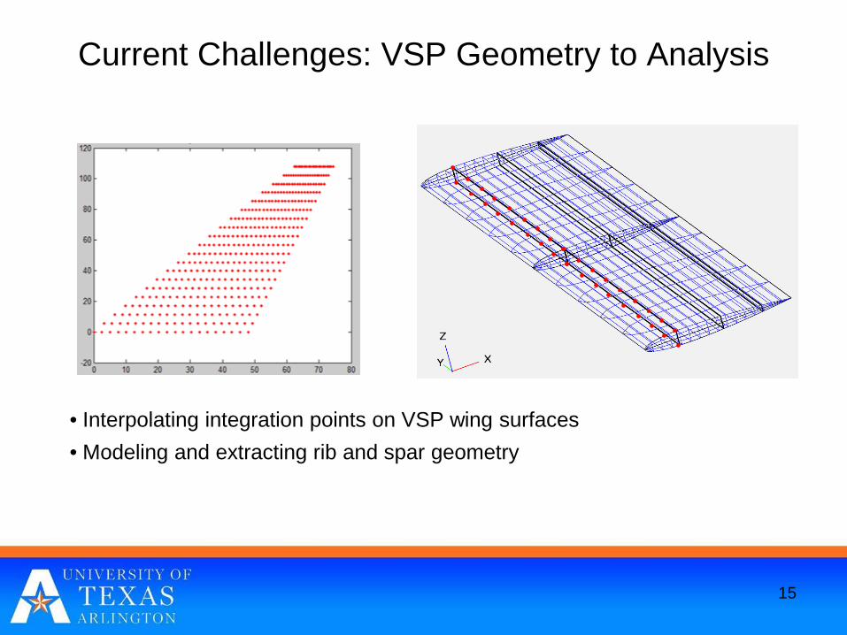
Current Challenges: VSP Geometry to Analysis
• Interpolating integration points on VSP wing surfaces• Modeling and extracting rib and spar geometry
15

Current Challenges: VSPAero Loads Interface
• How to acquire pressure distributions• Mapping/interpolating pressures from aero to structural mesh (Ritz or FEM)• Some desired capabilities
– Recovering results programmatically (pressure distribution, …)– Capability to configure and access massive numbers of runs– Ability to submit deformed geometry for analysis
16

Summary & Future Work
• A high order Ritz solution using Legendre polynomials developed to model quadrilateral VAT plates for static, vibration and buckling analyses
• Methodology is being extended to model tow-steered wing structures• Ritz and FEM solutions have demonstrated good agreement• Future plans
– Demonstrate a sizing framework– Explore parallelized solution strategies
17

Thank You and Questions
18