Torque Displacement Binding Tester...major components, a torque wrench, and a displacement sensor....
32
Torque-Displacement Binding Tester ME-CAB-1206 Design of a ski binding test device with torque and displacement sensing A Major Qualifying Project Report Submitted to the faculty of the WORCESTER POLYTECHNIC INSTITUTE in partial fulfillment of the requirements for the Degree of Bachelor of Science in Mechanical Engineering by Bradley Merrill _____________________________________________ In cooperation with Justin Lagassey _____________________________________________ Date: 3/12/2013 Approved: _____________________________________________ Prof. C A Brown, Major Advisor Keywords: 1) Alpine Ski Binding Tester 2) Torque Sensing 3) Displacement Sensing
Transcript of Torque Displacement Binding Tester...major components, a torque wrench, and a displacement sensor....
Torque-Displacement Binding Tester
ME-CAB-1206
Design of a ski binding test device with torque and displacement sensing
A Major Qualifying Project Report
Submitted to the faculty
of the
WORCESTER POLYTECHNIC INSTITUTE
in partial fulfillment of the requirements for the
Degree of Bachelor of Science
in Mechanical Engineering
by
Bradley Merrill
_____________________________________________
In cooperation with
Justin Lagassey
_____________________________________________
Date: 3/12/2013
Approved:
_____________________________________________
Prof. C A Brown, Major Advisor
Keywords:
1) Alpine Ski Binding
Tester
2) Torque Sensing
3) Displacement
Sensing

i
Abstract Inadvertent release of a ski binding occurs when the ski binding releases the skier under
non-injurious loading conditions and has been known to cause loss of control leading to
severe upper body injury and death. Work required to release the ski boot from the ski
binding is a parameter that influences the tendency for inadvertent release. The project
utilized Suh’s Axiomatic method for the design of a device that measures work to release
through the simultaneous measurements of torque and displacement. The optical mouse is
tested and recommended as a low cost displacement sensor.

ii
Acknowledgements We thank:
Robert Johnson, Jasper E. Shealy, and Carl Ettlinger for their dedication to skier safety,
Rick Howell, for enlightening us on ski binding design,
and Professor Christopher A. Brown, for advising us through to the completion of our
project’s success.

iii
Table of Contents Abstract ...................................................................................................................................................................... i
Acknowledgements .............................................................................................................................................. ii
Table of Figures ..................................................................................................................................................... v
1. Introduction ................................................................................................................................................... 1
1.1 Objective ....................................................................................................................................................... 1
1.2 Rationale....................................................................................................................................................... 1
1.3 State of the Art ........................................................................................................................................... 2
1.4 Approach ...................................................................................................................................................... 4
2. Design Decompositions and Constraints ............................................................................................ 4
2.1 Zero level Decomposition Theme ....................................................................................................... 5
2.2 First Level Decomposition Theme...................................................................................................... 5
2.3.0 General Statement First Level Decomposition ...................................................................... 6
2.3.1 FR1 – Functional Requirement 1 ................................................................................................ 6
2.3.2 DP1 – Design Parameter 1 ............................................................................................................ 6
2.3.4 FR2 ......................................................................................................................................................... 7
2.3.5 DP2 ......................................................................................................................................................... 7
2.3.6 FR3 ......................................................................................................................................................... 7
2.3.7 DP3 ......................................................................................................................................................... 7
2.3.8 FR4 ......................................................................................................................................................... 7
2.4 Second Level Decomposition Theme ................................................................................................ 7
2.4.0 General Statement Second Level Decomposition ................................................................ 8
2.4.1 FRi.1 ....................................................................................................................................................... 8
2.4.2 DPi.1 ....................................................................................................................................................... 8
2.4.3 FRi.2 ....................................................................................................................................................... 9
2.4.4 DPi.2 ....................................................................................................................................................... 9
2.4.5 FRi.3 ....................................................................................................................................................... 9
2.4.6 DPi.3 ....................................................................................................................................................... 9
3. Physical Integration......................................................................................................................................... 9
3.1 Introduction of New Constraints ..................................................................................................... 10
3.2 Displacement Sensing .......................................................................................................................... 10
iv
3.3 Displacement Calibration ................................................................................................................... 13
3.4 Torque Sensing ....................................................................................................................................... 13
3.5 Combining Signals ................................................................................................................................. 14
4. Testing of the Final Design ........................................................................................................................ 15
4.1 Displacement testing ............................................................................................................................ 15
4.1.1 Materials ........................................................................................................................................... 16
4.1.2 Jig Preparation ................................................................................................................................ 16
4.2 Linearity Testing .................................................................................................................................... 17
4.3 Precision Testing .................................................................................................................................... 18
5. Discussion ........................................................................................................................................................ 20
5.1 Accomplishments ................................................................................................................................... 20
5.2 Societal Context ...................................................................................................................................... 20
5.3 Deficiency in Prior art and Considerations .................................................................................. 20
5.3.1Program Design ............................................................................................................................... 20
5.3.2 Multiple Mice ................................................................................................................................... 21
5.3.3 Mechanical Considerations ........................................................................................................ 21
5.4 Commercial Use ...................................................................................................................................... 21
6. Concluding Remarks .................................................................................................................................... 21
7. Works Cited ..................................................................................................................................................... 23
8. Appendix A ....................................................................................................................................................... 25
v
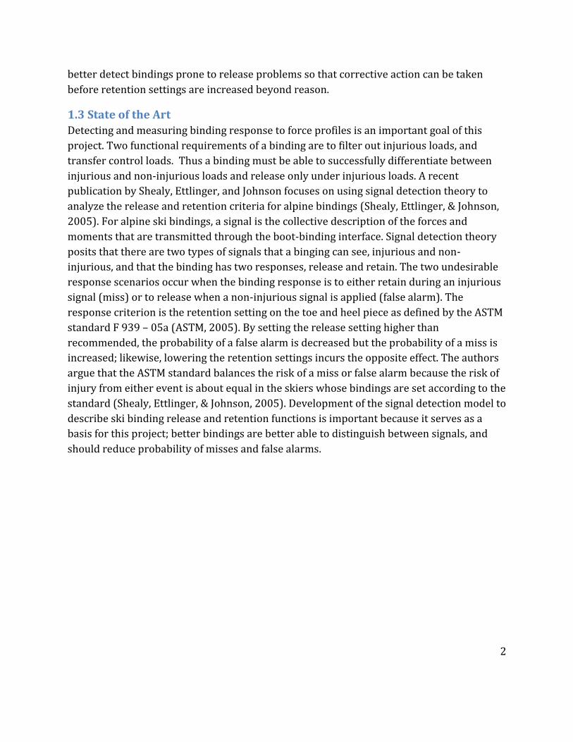
Table of Figures Figure 1: Signal Detection: (Heeger, 1998) ................................................................................................ 3
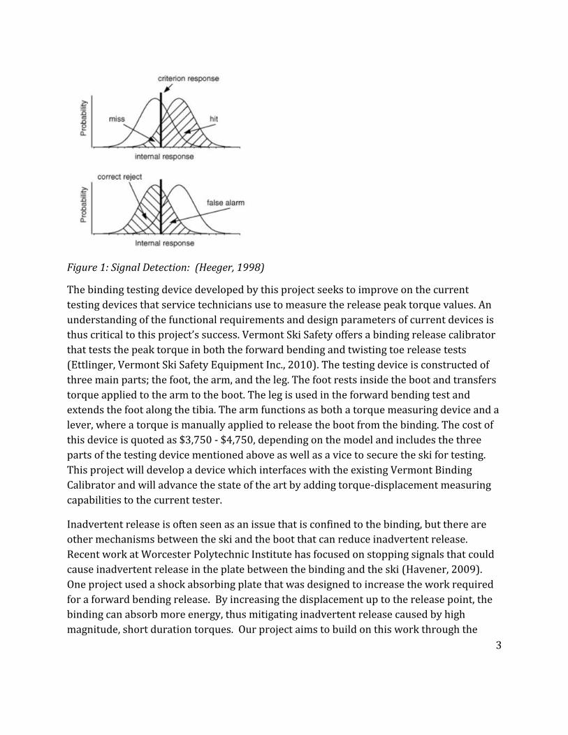
Figure 2: Test Axes (ASTM, 2005) .................................................................................................................. 5
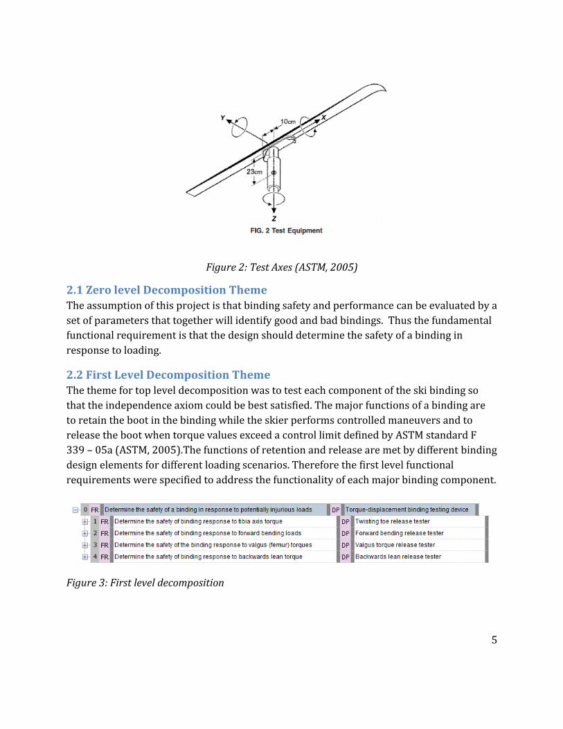
Figure 3: First level decomposition ............................................................................................................... 5
Figure 4: Design is decoupled and therefore satisfies independence axiom ................................. 6
Figure 5: The second level of axiomatic decomposition, notice the FR repetitiveness ............. 8
Figure 6: Displacement VI ............................................................................................................................... 11
Figure 7: Mouse Settings ................................................................................................................................. 12
Figure 9: Strain Null and Shunt Calibration ............................................................................................. 13
Figure 10: Strain output .................................................................................................................................. 14
Figure 11: Testing Apparatus ........................................................................................................................ 15
Figure 12: Jig for displacement testing ...................................................................................................... 16
Figure 13: Pixel vs. Real Displacement ...................................................................................................... 17
Figure 14: Displacement Calibration .......................................................................................................... 18
Figure 15: Sample Distribution .................................................................................................................... 19
Figure 16: Random Number Distribution ................................................................................................ 19
1
1. Introduction
1.1 Objective
The objective of this Major Qualifying Project is to design a device that can evaluate the
susceptibility for inadvertent release of alpine ski bindings by measuring the work
required to release the ski boot from the binding. Inadvertent release is defined as a release
of the ski binding under loads that are not injurious to the skier.
1.2 Rationale
Testing susceptibility for inadvertent release is important because inadvertent release can
lead to loss of control at high velocity and cause life threatening collisions. During high
velocity collisions, a greater impact force is required to slow the skier, increasing the risk
for serious or fatal injury. According to the National Ski Areas Association, in 2011 there
were 31 fatal skiing injuries (Hawks, 2011). The most prevalent mechanism of skier death
involved impact with an object or person (Langran, 2012). Loss of control due to
inadvertent release is a contributing factor in some of these collisions, and is especially
likely when the skier fights for control and maintains velocity after losing one ski.
Inadvertent release is not well understood or recognized by most recreational skiers.
Although inadvertent release is reported as causing only 1% of skiing injuries (Shealy,
Ettlinger, & Johnson, 2005), the rate of inadvertent release injuries is
likely underreported due to lack of awareness by the general public. Most skiers do not
know what inadvertent release is, so it likely goes undetected as a cause for many
accidents. Another cause of underreporting is that the casualty of an inadvertent release
accident may be unable to recall the specific order of events surrounding the injury,
especially when the casualty suffers a traumatic brain injury.
Identifying bindings that are prone to inadvertent release is also important because users
who experience inadvertent release often react by increasing their retention settings
beyond the settings recommended by the ASTM standard F 939 – 05a (ASTM, 2005).
Increased settings may lead to greater risk for lower extremity equipment related (LEER)
injury. One study found that bindings failed to release in 96% of all LEER injuries and that
advanced skiers have higher binding retention settings than intermediate and novice
skiers, even when controlling for weight and skier type (Urabe, Ochi, Onari, & Ikuta, 2002).
The tendency to increase release settings in response to inadvertent release has been
nicknamed the "ratchet effect" because skiers who increase their settings rarely lower the
settings (Ettlinger, 2010). It would be beneficial for ski technicians to have a device that can
2
better detect bindings prone to release problems so that corrective action can be taken
before retention settings are increased beyond reason.
1.3 State of the Art
Detecting and measuring binding response to force profiles is an important goal of this
project. Two functional requirements of a binding are to filter out injurious loads, and
transfer control loads. Thus a binding must be able to successfully differentiate between
injurious and non-injurious loads and release only under injurious loads. A recent
publication by Shealy, Ettlinger, and Johnson focuses on using signal detection theory to
analyze the release and retention criteria for alpine bindings (Shealy, Ettlinger, & Johnson,
2005). For alpine ski bindings, a signal is the collective description of the forces and
moments that are transmitted through the boot-binding interface. Signal detection theory
posits that there are two types of signals that a binging can see, injurious and non-
injurious, and that the binding has two responses, release and retain. The two undesirable
response scenarios occur when the binding response is to either retain during an injurious
signal (miss) or to release when a non-injurious signal is applied (false alarm). The
response criterion is the retention setting on the toe and heel piece as defined by the ASTM
standard F 939 – 05a (ASTM, 2005). By setting the release setting higher than
recommended, the probability of a false alarm is decreased but the probability of a miss is
increased; likewise, lowering the retention settings incurs the opposite effect. The authors
argue that the ASTM standard balances the risk of a miss or false alarm because the risk of
injury from either event is about equal in the skiers whose bindings are set according to the
standard (Shealy, Ettlinger, & Johnson, 2005). Development of the signal detection model to
describe ski binding release and retention functions is important because it serves as a
basis for this project; better bindings are better able to distinguish between signals, and
should reduce probability of misses and false alarms.
3
Figure 1: Signal Detection: (Heeger, 1998)
The binding testing device developed by this project seeks to improve on the current
testing devices that service technicians use to measure the release peak torque values. An
understanding of the functional requirements and design parameters of current devices is
thus critical to this project’s success. Vermont Ski Safety offers a binding release calibrator
that tests the peak torque in both the forward bending and twisting toe release tests
(Ettlinger, Vermont Ski Safety Equipment Inc., 2010). The testing device is constructed of
three main parts; the foot, the arm, and the leg. The foot rests inside the boot and transfers
torque applied to the arm to the boot. The leg is used in the forward bending test and
extends the foot along the tibia. The arm functions as both a torque measuring device and a
lever, where a torque is manually applied to release the boot from the binding. The cost of
this device is quoted as $3,750 - $4,750, depending on the model and includes the three
parts of the testing device mentioned above as well as a vice to secure the ski for testing.
This project will develop a device which interfaces with the existing Vermont Binding
Calibrator and will advance the state of the art by adding torque-displacement measuring
capabilities to the current tester.
Inadvertent release is often seen as an issue that is confined to the binding, but there are
other mechanisms between the ski and the boot that can reduce inadvertent release.
Recent work at Worcester Polytechnic Institute has focused on stopping signals that could
cause inadvertent release in the plate between the binding and the ski (Havener, 2009).
One project used a shock absorbing plate that was designed to increase the work required
for a forward bending release. By increasing the displacement up to the release point, the
binding can absorb more energy, thus mitigating inadvertent release caused by high
magnitude, short duration torques. Our project aims to build on this work through the

4
development of a reproducible testing procedure that will encourage the measurement of
work to release as a standard metric.
1.4 Approach
The current ASTM standard for maintenance level ski binding testing is focused on two
parameters; torque required for lateral toe release, and torque required for vertical heel
release (ASTM, 2005).These two parameters measure only maximum torque, however the
rate at which energy is absorbed by the binding (work-to-release), and the ability to return
to center are crucial for determining the safe performance of a binding. Bindings that can
absorb more energy prior to release likely have a lower tendency for inadvertent release.
Although currently possible, it is prohibitively expensive for most retailers to test the
displacement of a boot in a ski binding while simultaneously measuring the applied torque.
This testing is typically only performed to gain certification for new bindings, and costs
thousands of dollars per test (Howell, 2012; International Standard, 2006). Most skiers are
therefore unaware if their bindings may have a tendency to release inadvertently.
The primary objective of this project is to complete a prototype device that can measure
work to release of a ski boot from a ski binding at an affordable cost to most ski shops;
under $500. The decomposition for a device that satisfies this functional requirement was
realized using Suh’s axiomatic design method. The testing apparatus will consist of two
major components, a torque wrench, and a displacement sensor. By measuring these two
parameters simultaneously and integrating the area under the torque/displacement curve,
the work to release can be calculated.
2. Design Decompositions and Constraints Axiomatic design was used to organize the design of the binding tester. The collectively
exhaustive principal of axiomatic decomposition ensures that the problem was thoroughly
reviewed and described completely. The mutually exclusive principal organizes the design
to minimize the information content and make the problem as simple as possible.
5
Figure 2: Test Axes (ASTM, 2005)
2.1 Zero level Decomposition Theme
The assumption of this project is that binding safety and performance can be evaluated by a
set of parameters that together will identify good and bad bindings. Thus the fundamental
functional requirement is that the design should determine the safety of a binding in
response to loading.
2.2 First Level Decomposition Theme
The theme for top level decomposition was to test each component of the ski binding so
that the independence axiom could be best satisfied. The major functions of a binding are
to retain the boot in the binding while the skier performs controlled maneuvers and to
release the boot when torque values exceed a control limit defined by ASTM standard F
339 – 05a (ASTM, 2005).The functions of retention and release are met by different binding
design elements for different loading scenarios. Therefore the first level functional
requirements were specified to address the functionality of each major binding component.
Figure 3: First level decomposition
6
2.3.0 General Statement First Level Decomposition
FRi “Determine the safety of the binding response to (z, +y, x through knee, -y) type of
torque” for i = {1,2,3,4}, respectively. This form of functional requirement has three
statements. “Determine the safety” means that the test must be able to distinguish between
safe and unsafe bindings and that the parameters used are good indicators of field
performance. “Of the binding response” means that the binding reacts appropriately in an
unsafe loading scenario, and that this response is repeatable. “(z, +y, x through knee, -y)
type of torque” identifies the axis about which torque is applied and the direction of the
torque. This approach assumes that torque is the primary cause of injury.
2.3.1 FR1 – Functional Requirement 1
The first of two primary release mechanisms that almost all bindings have incorporated
since the 1960’s is the twisting toe release for torques applied about the z-axis, commonly
called tibia torque (Beyl, 1962). Danger associated with inadvertent release in the toe piece
is well-documented and has been reported in the literature (Brown, Hoffman, &
Heinzmann, 1996). The effectiveness of binding response to tibia axis torques is critical to
the function of the binding.
2.3.2 DP1 – Design Parameter 1
The binding testing apparatus for tibia torque is generalized at this level, although the
concept is expanded to include continuous torque and displacement monitoring of the
boot-binding system. The design suffers from a small degree of coupling because certain
components are reused in the forward bending tester. This coupling is not a major issue
because the components are used in different configurations and the transitions between
configurations is necessary for existing designs (Ettlinger, Vermont Ski Safety Equipment
Inc., 2010). The coupling becomes an issue if testing multiple loads simultaneously.
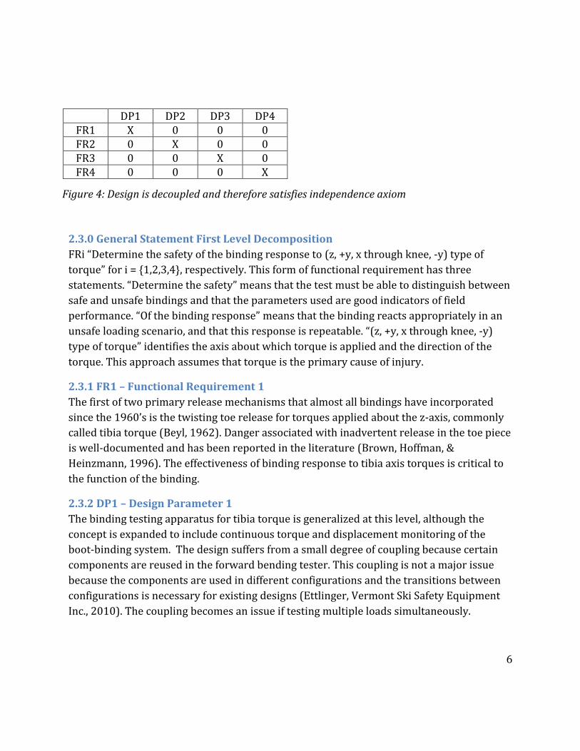
DP1 DP2 DP3 DP4 FR1 X 0 0 0 FR2 0 X 0 0 FR3 0 0 X 0 FR4 0 0 0 X
Figure 4: Design is decoupled and therefore satisfies independence axiom
7
2.3.4 FR2
The other major release mechanism is the vertical heel release for positive torques applied
about the y-axis, commonly known as forward bending torque. This release mechanism is
designed to prevent injury to the tibia such as boot-top fractures or a rupture of the
Achilles tendon. Popularized in the 1970’s, releasable heels have been in use almost as long
as toe pieces (Brown C. A., 2006). The same concerns for the releasable toe piece apply to
the heel; the binding must transmit control loads and not transmit injurious loads, from the
ski to the skier.
2.3.5 DP2
The forward bending tester is similar to the tibia torque tester, but is aligned such that the
torque and angular displacement is measured about the y-axis. Like the tibia torque tester
there is continuous monitoring of the torque and the displacement of the boot-binding
system.
2.3.6 FR3
Some newer bindings, such as Tyrolia’s diagonal bindings, have incorporated vertical toe
release to respond to negative torque applied about the y-axis (backward bending torque)
(Tyrolia, 2013). The incorporation of this moment in the design criteria is in anticipation
that the availability of a binding tester for these loading scenarios will encourage binding
companies to improve current designs.
2.3.7 DP3
The binding tester follows the same procedure as the forward bending procedure but in the
opposite direction.
2.3.8 FR4
One manufacturer, Knee Binding, has introduced a lateral heel release function to address
force applied directly underfoot that produces a torque about an axis parallel to the x-axis
and through the knee (Pure Lateral, 2013). Many bindings are not designed to protect
skiers from these loading scenarios and the availability of this testing device might pave
way towards safer bindings.
2.4 Second Level Decomposition Theme
The theme for second level decomposition is release-retention criteria. The release
criterion is that the binding release the boot when the acted upon by an injurious torque.
The retention criterion is that the binding absorb non-injurious loads that momentarily
exceed the control limit. During normal skiing maneuvers, especially in racing, the applied
load to the ski will momentarily exceed the control values for release. This is measured by
the amount of energy that the binding can absorb before a release. In application, the
8
energy absorbed is the integral of torque with respect to the angular displacement. The
binding absorbs energy by allowing the boot to displace in the binding for a short distance,
and returns to center when the applied load drops below the control limit.
The release criterion for the binding test is defined by a metric that measures the tolerance
on the maximum torque transmitted to the boot during release. The retention criterion for
the binding tester is based on the amount of energy absorbed before a release occurs and
should be maximized. These two metrics are linked by the measurement of torque so the
decomposition was decomposed by torque, displacement and analysis. This satisfies the
independence axiom by decoupling release and retention in the analysis functional
requirement. The decomposition is exhaustive and mutually exclusive.
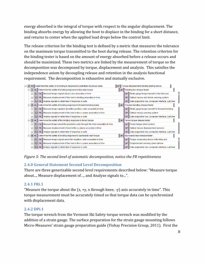
Figure 5: The second level of axiomatic decomposition, notice the FR repetitiveness
2.4.0 General Statement Second Level Decomposition
There are three generizable second level requirements described below: “Measure torque
about..., Measure displacement of…, and Analyze signals to...”.
2.4.1 FRi.1
“Measure the torque about the (z, +y, x through knee, -y) axis accurately in time”. This
torque measurement must be accurately timed so that torque data can be synchronized
with displacement data.
2.4.2 DPi.1
The torque wrench from the Vermont Ski Safety torque wrench was modified by the
addition of a strain gauge. The surface preparation for the strain gauge mounting follows
Micro-Measures’ strain gauge preparation guide (Vishay Precision Group, 2011). First the

9
metallic surface was degreased, and wet abrased using progressively finer silicon carbide
paper. The surfaced was then neutralized with M-Prep neutralizer, and Loctite 496 was
used to bond the strain gauge to the surface. Lead wires were soldered onto the strain
gauge and the whole unit was submersed in hot glue to prevent the gauge and solder from
damage.
2.4.3 FRi.2
“Measure the displacement of the boot in the (z, +y, x through knee, -y) plane accurately in
time”. The displacement measurement, like torque, must be accurately timed so that the
data can be synchronized.
2.4.4 DPi.2
The displacement sensing involved a rigid target of carboard attached to the boot such that
the optical mouse could be held against it. The exact configuration of the mouse and target
changed considerabley depending on the type of release being tested, but the setup worked
through maintaining pressure between the target and the mouse, while keeping the mouse
fixed during boot displacement.
2.4.5 FRi.3
“Analyze signals to determine if the response is safe”. The analysis functional requirement
deals with the computation of the release and retention metrics. This is the final treatment
of the data and determines work-to-release.
2.4.6 DPi.3
The signals were acquired and digitalized through a data acquisition box and were
processed in LabView software with final analytics completed in excel.
3. Physical Integration For a device to successfully evaluate the susceptibility for inadvertent release of alpine ski
bindings, the device must be capable of differentiating between high-performing and poor-
performing bindings. The tolerance provided by the torque sensor should satisfy the
performance requirements set forth in ANSI F1061 – 97, and the tolerance provided by the
displacement sensor should satisfy the ISO 9462 return-to-center test. Torque and
displacement sensing options that meet the preceding standards were explored. The
difficulty in measuring work-to-release arises with synchronizing the displacement and
torque time signals. Although these two parameters can be observed relatively easily as
separate analog signals, it becomes challenging to process this data simultaneously without
the use of digital signal processing. After failed attempts of using a high speed camera to
physically couple a torque and a displacement reading, it was realized that other digital
10
methods need be explored. Consequently, LabView provides a user friendly option for data
acquisition and data manipulation.
3.1 Introduction of New Constraints
New constraints were generated when LabView was selected as the interface for data
acquisition. The sensors that be chosen must be able to convert physical displacement and
torque signals to electrical signals; the analog electrical signals must then be converted to
digital signals so that they can be read by a PC. Different transducers, which convert
mechanical energy into electrical energy, were explored for their use as torque and strain
sensors.
Programming knowledge now constrained the feasibility of fulfilling most of the functional
requirements described in chapter 2. The time constraint thus had the greatest influence
on the overarching functional requirements of this project. Programming knowledge can be
improved over time but more importantly it takes time to complete the project. Inherently
there is functional coupling that would influence the direction of the project. The process
integration described below aims at collecting the data necessary to measure work-to-
release, however design suggestions that adhere to the original FR-DP matrix are listed in
the discussion section.
3.2 Displacement Sensing
Due to high volume production, the optical mouse offers a high resolution displacement
sensing option at nearly 2% the cost of conventional displacement sensors, such as LVDT
(linear variable differential transformer) and RVDT (rotary variable differential
transformer) sensors. Unlike mechanical-electrical displacement transducers, an optical
mouse converts an electromagnetic signal, light, to an electrical signal by reflecting LED
light off of a surface onto a CMOS (complementary metal-oxide semiconductor) sensor and
compares surface images thousands of times per second in a DSP (Digital Signal Processor)
(Ng, 2003). Its position is determined relative to how well the previous image matches up
to the current. Although not a suitable displacement transducer for all applications, namely
when taking measurements on reflective surfaces or over large distances, the optical
mouse was investigated for displacement measurements of ski boots during ski-binding
torque tests.
In a 2003 study by T.W. Ng of The National University of Singapore, it was determined that
an optical mouse can function as an effective two-dimensional displacement sensor when
measuring small distances on opaque surfaces (Ng, 2003). In this study an optical mouse
was displaced 1mm horizontally and 1mm vertically: The mean square error calculated
was .018mm2 and the mean R2 value was .9914. Before physical integration with the ski-
11
binding testing device, further testing was performed to determine whether this high
repeatability could be reproducible during mouse displacements correlating with distances
a ski boot travels during binding torque tests. The results of these tests can be found in
chapter 4.
An optical mouse, although capable of measuring displacement, is intended to provide
interface for human interaction, hence the acronym HID (human interface device).
Therefore, it is necessary to reverse engineer the mouse to an extent where displacement
data can be acquired. The original displacement Virtual Instrument (VI) that was created
for displacement sensing can be seen below in Figure 6.
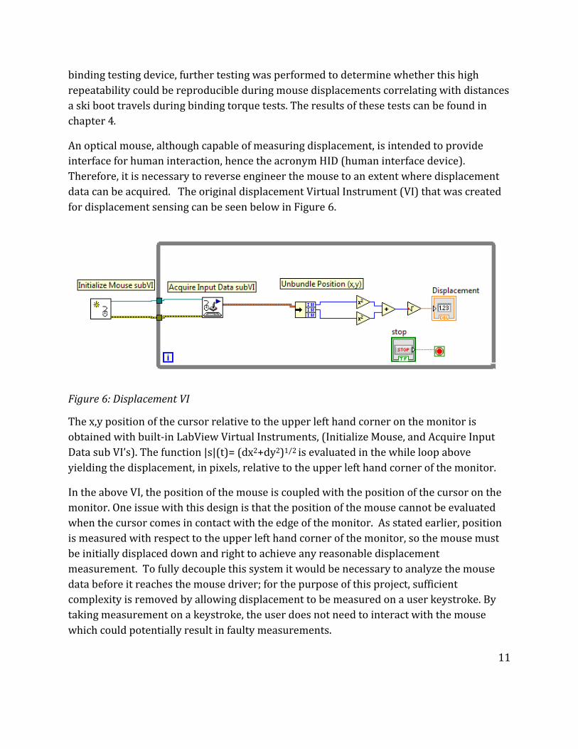
Figure 6: Displacement VI
The x,y position of the cursor relative to the upper left hand corner on the monitor is
obtained with built-in LabView Virtual Instruments, (Initialize Mouse, and Acquire Input
Data sub VI’s). The function |s|(t)= (dx2+dy2)1/2 is evaluated in the while loop above
yielding the displacement, in pixels, relative to the upper left hand corner of the monitor.
In the above VI, the position of the mouse is coupled with the position of the cursor on the
monitor. One issue with this design is that the position of the mouse cannot be evaluated
when the cursor comes in contact with the edge of the monitor. As stated earlier, position
is measured with respect to the upper left hand corner of the monitor, so the mouse must
be initially displaced down and right to achieve any reasonable displacement
measurement. To fully decouple this system it would be necessary to analyze the mouse
data before it reaches the mouse driver; for the purpose of this project, sufficient
complexity is removed by allowing displacement to be measured on a user keystroke. By
taking measurement on a keystroke, the user does not need to interact with the mouse
which could potentially result in faulty measurements.
12
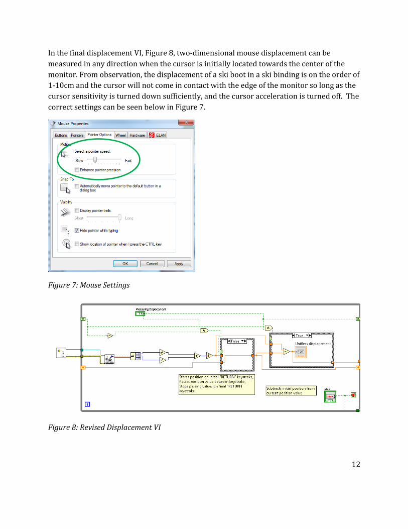
In the final displacement VI, Figure 8, two-dimensional mouse displacement can be
measured in any direction when the cursor is initially located towards the center of the
monitor. From observation, the displacement of a ski boot in a ski binding is on the order of
1-10cm and the cursor will not come in contact with the edge of the monitor so long as the
cursor sensitivity is turned down sufficiently, and the cursor acceleration is turned off. The
correct settings can be seen below in Figure 7.
Figure 7: Mouse Settings
Figure 8: Revised Displacement VI
13
3.3 Displacement Calibration
The displacement VI measures the cursor’s displacement in pixels; thus the pixel
displacement needs to be converted to a unit displacement for measuring work. By
displacing the optical mouse a known distance, a function relating pixel displacement to the
known displacement can be calculated. By nature of optical mouse operation there is a
degree of systematic, as well as random error that exists in its measurements. Methods for
improving the accuracy and repeatability of the measurements were explored. By using the
same or a similar surface for calibration as for taking measurements the systematic error
can be decreased. Likewise, if the measurement surface is displaced linearly such that the
CMOS operates on nearly an identical trajectory, random error caused by surface
irregularities should recur across multiple measurements, increasing the repeatability of
the results.
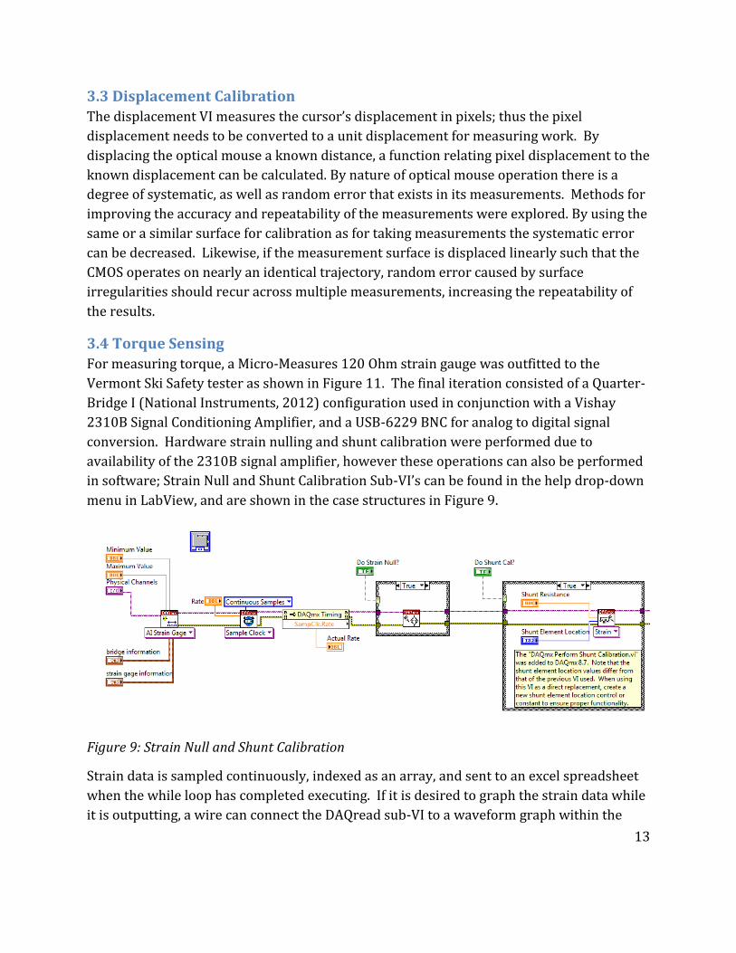
3.4 Torque Sensing
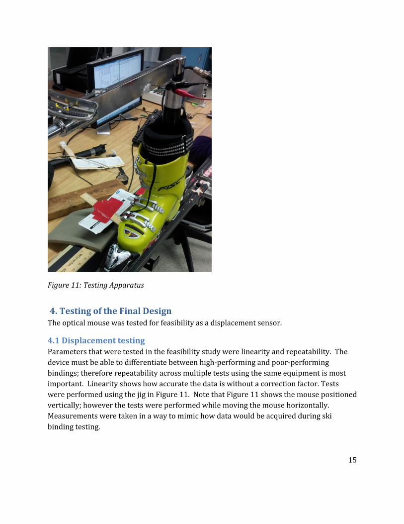
For measuring torque, a Micro-Measures 120 Ohm strain gauge was outfitted to the
Vermont Ski Safety tester as shown in Figure 11. The final iteration consisted of a Quarter-
Bridge I (National Instruments, 2012) configuration used in conjunction with a Vishay
2310B Signal Conditioning Amplifier, and a USB-6229 BNC for analog to digital signal
conversion. Hardware strain nulling and shunt calibration were performed due to
availability of the 2310B signal amplifier, however these operations can also be performed
in software; Strain Null and Shunt Calibration Sub-VI’s can be found in the help drop-down
menu in LabView, and are shown in the case structures in Figure 9.
Figure 9: Strain Null and Shunt Calibration
Strain data is sampled continuously, indexed as an array, and sent to an excel spreadsheet
when the while loop has completed executing. If it is desired to graph the strain data while
it is outputting, a wire can connect the DAQread sub-VI to a waveform graph within the
14
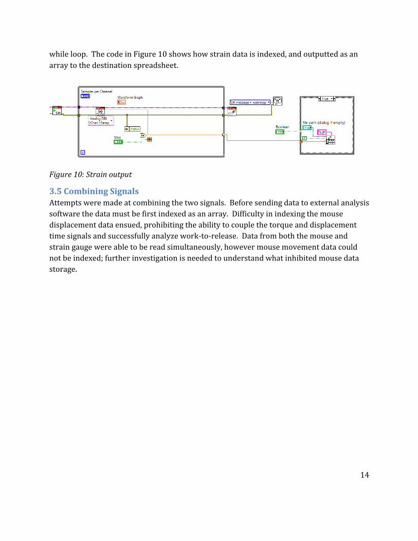
while loop. The code in Figure 10 shows how strain data is indexed, and outputted as an
array to the destination spreadsheet.
Figure 10: Strain output
3.5 Combining Signals
Attempts were made at combining the two signals. Before sending data to external analysis
software the data must be first indexed as an array. Difficulty in indexing the mouse
displacement data ensued, prohibiting the ability to couple the torque and displacement
time signals and successfully analyze work-to-release. Data from both the mouse and
strain gauge were able to be read simultaneously, however mouse movement data could
not be indexed; further investigation is needed to understand what inhibited mouse data
storage.
15
Figure 11: Testing Apparatus
4. Testing of the Final Design The optical mouse was tested for feasibility as a displacement sensor.
4.1 Displacement testing
Parameters that were tested in the feasibility study were linearity and repeatability. The
device must be able to differentiate between high-performing and poor-performing
bindings; therefore repeatability across multiple tests using the same equipment is most
important. Linearity shows how accurate the data is without a correction factor. Tests
were performed using the jig in Figure 11. Note that Figure 11 shows the mouse positioned
vertically; however the tests were performed while moving the mouse horizontally.
Measurements were taken in a way to mimic how data would be acquired during ski
binding testing.

16
1.
2
3.
4.
5.
6.
Figure 12: Jig for displacement testing
4.1.1 Materials
LabView is opened and the displacement VI from Figure 8 is ran. The following materials
were used in this experiment:
1. 2 X .5” thickness wood sheet
2. 1 X Vernier Caliper with .001” graduations
3. 1 X Logitech M305 wireless mouse
4. 1 X Sheet of paper
5. 2 X 90ᵒ steel supports
6. 3 X C-Clamps,
7. 1 X PC
4.1.2 Jig Preparation
To prepare the jig, the lower steel support is clamped down to the base wood, with the
paper in between. The second wood piece is placed at a right angle against the steel
support and clamped down, also to the base wood. The Vernier caliper is then clamped in a
way that the outer jaw closest to the dial is secure against the steel support, and the free
jaw extends collinearly with the edge of the top wood sheet.
Displacement
d
Mouse
width
d
Distance
between
supports

17
4.2 Linearity Testing
The second steel support is set an unknown distance away from the clamped steel support,
forming a right angle with the top wood piece. This distance is measured with the Vernier
caliper and recorded in Excel. The width of the mouse is also measured and recorded.
The mouse is then moved linearly from the first steel support until it contacts the second
support. The displacement in LabView is recorded. This is performed twice more, and the
mean of the three displacements is calculated. This procedure is repeated 14 more times,
gradually increasing the distance between the steel supports. The final distance the mouse
moves is 1.645”. The mouse width is subtracted from the measured distance between the
supports, yielding the actual distance that the mouse moved. The pixel displacement
(optical mouse measurement) is then plotted as a function of the actual displacement
(Vernier Caliper measurement). The results in Figure 13 below indicate linear correlation
between pixel displacement and actual displacement.
Figure 13: Pixel vs. Real Displacement
18
Note that the mouse was moved from the same initial position on each test. Moving the
mouse intermittently, such that it only moves in one direction, never returning to the initial
position was attempted; however the results were very non-linear. This is likely due to
error propagation of the initial acceleration and final deceleration on every measurement.
Performing the experiment using the first testing procedure is representative of how the
mouse would measure displacement during binding torque tests, as displacement of the ski
boot is also continuous during these tests.
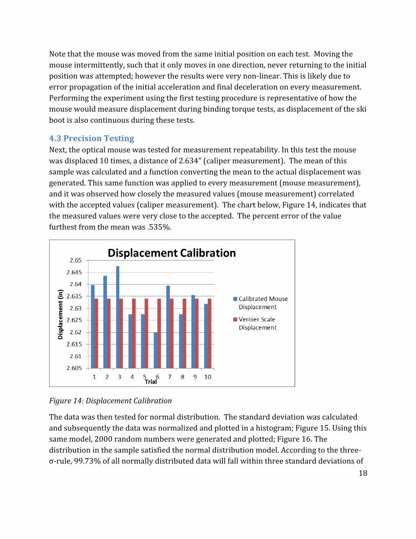
4.3 Precision Testing
Next, the optical mouse was tested for measurement repeatability. In this test the mouse
was displaced 10 times, a distance of 2.634” (caliper measurement). The mean of this
sample was calculated and a function converting the mean to the actual displacement was
generated. This same function was applied to every measurement (mouse measurement),
and it was observed how closely the measured values (mouse measurement) correlated
with the accepted values (caliper measurement). The chart below, Figure 14, indicates that
the measured values were very close to the accepted. The percent error of the value
furthest from the mean was .535%.
Figure 14: Displacement Calibration
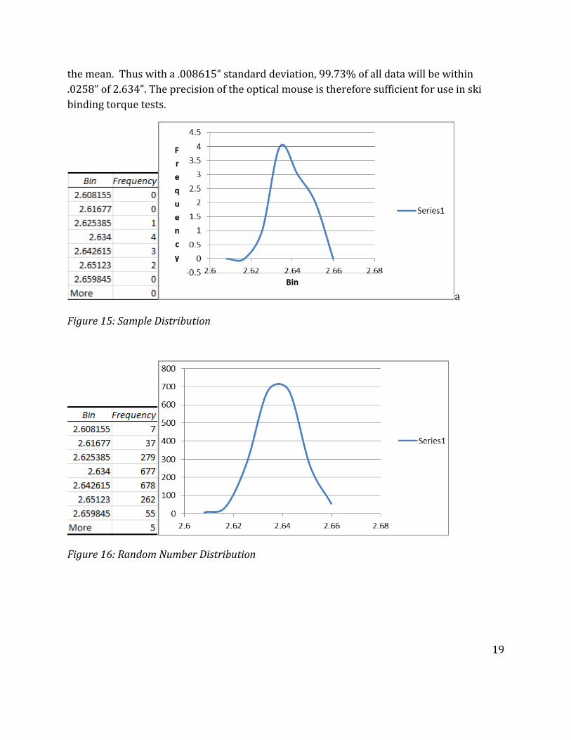
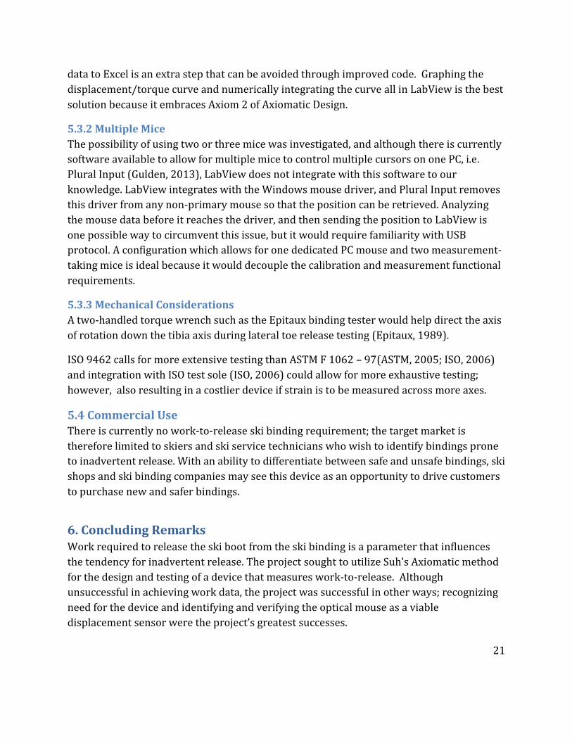
The data was then tested for normal distribution. The standard deviation was calculated
and subsequently the data was normalized and plotted in a histogram; Figure 15. Using this
same model, 2000 random numbers were generated and plotted; Figure 16. The
distribution in the sample satisfied the normal distribution model. According to the three-
σ-rule, 99.73% of all normally distributed data will fall within three standard deviations of
19
the mean. Thus with a .008615” standard deviation, 99.73% of all data will be within
.0258” of 2.634”. The precision of the optical mouse is therefore sufficient for use in ski
binding torque tests.
a
Figure 15: Sample Distribution
Figure 16: Random Number Distribution

20
5. Discussion
5.1 Accomplishments
The objective of this Major Qualifying Project was to design a device that can evaluate the
susceptibility for inadvertent release of alpine ski bindings by measuring the work
required to release the ski boot from the binding. Due to programming difficulties the team
was unable to acquire the data necessary for calculating work-to-release; the project was
successful in other aspects.
Recognizing the need for a ski binding work-to-release testing device is a significant step
towards better ski binding design. Value is defined by a device’s functional requirements; a
method for quantifying the functional requirements is therefore essential for recognizing a
device’s value. Work-to-release is an indication of a ski binding’s performance; however no
device is currently available for measuring this parameter.
A major accomplishment of this project was identifying and verifying the optical mouse as
a viable displacement sensor in ski binding testing. Optical mice may be overlooked as
displacement sensors; they are not displacement transducers in of themselves, but
electromagnetic transducers.
5.2 Societal Context
The first Fundamental Engineering Canon states that, “Engineers shall…hold paramount
the safety, health, and welfare of the public” (NCEES, 2013). Engineering Standards play a
pivotal part in protecting our role as engineers. A National Standards Body will normally
determine a market need for a standard (ISO, 2009). Market need may be qualified for a
number of reasons; in the context of this project, the market need is safeguarding the
interests of the skiing public. The most outreaching goal of the torque-displacement
binding sensor is to prevent skier death. The probability of severe skier injury or death is
low, but it is present nonetheless. Without the introduction of a standard requiring ski
binding companies to disclose work-to-release, there is low market potential for this this
device.
5.3 Deficiency in Prior art and Considerations
Deficiency in the prior art and considerations for eliminating said deficiency are listed
below.
5.3.1Program Design
By minimizing the user-information required to iterate the work-to-release measurements,
the device becomes more intuitive. LabView has capability for every calculation to be
performed in its own code without the need for external data analysis software; sending
21
data to Excel is an extra step that can be avoided through improved code. Graphing the
displacement/torque curve and numerically integrating the curve all in LabView is the best
solution because it embraces Axiom 2 of Axiomatic Design.
5.3.2 Multiple Mice
The possibility of using two or three mice was investigated, and although there is currently
software available to allow for multiple mice to control multiple cursors on one PC, i.e.
Plural Input (Gulden, 2013), LabView does not integrate with this software to our
knowledge. LabView integrates with the Windows mouse driver, and Plural Input removes
this driver from any non-primary mouse so that the position can be retrieved. Analyzing
the mouse data before it reaches the driver, and then sending the position to LabView is
one possible way to circumvent this issue, but it would require familiarity with USB
protocol. A configuration which allows for one dedicated PC mouse and two measurement-
taking mice is ideal because it would decouple the calibration and measurement functional
requirements.
5.3.3 Mechanical Considerations
A two-handled torque wrench such as the Epitaux binding tester would help direct the axis
of rotation down the tibia axis during lateral toe release testing (Epitaux, 1989).
ISO 9462 calls for more extensive testing than ASTM F 1062 – 97(ASTM, 2005; ISO, 2006)
and integration with ISO test sole (ISO, 2006) could allow for more exhaustive testing;
however, also resulting in a costlier device if strain is to be measured across more axes.
5.4 Commercial Use
There is currently no work-to-release ski binding requirement; the target market is
therefore limited to skiers and ski service technicians who wish to identify bindings prone
to inadvertent release. With an ability to differentiate between safe and unsafe bindings, ski
shops and ski binding companies may see this device as an opportunity to drive customers
to purchase new and safer bindings.
6. Concluding Remarks Work required to release the ski boot from the ski binding is a parameter that influences
the tendency for inadvertent release. The project sought to utilize Suh’s Axiomatic method
for the design and testing of a device that measures work-to-release. Although
unsuccessful in achieving work data, the project was successful in other ways; recognizing
need for the device and identifying and verifying the optical mouse as a viable
displacement sensor were the project’s greatest successes.

22
Skiers would likely pay to know if their bindings have a tendency to release inadvertently
however most skiers do not even know what inadvertent release is. The first step towards
safer binding design is therefore educating the skiing public. The work-to-release binding
tester could accelerate the development of better bindings, by helping to recognize
imperfections in current bindings.
In the context of ski bindings, quantitative data should be more important to the consumer
than its qualitative characteristics. By current standards, the only quantitative metrics
widely accessible to consumers are the peak torque range, and number of release modes.
With the advent of a work-to-release binding tester, skiers will be able to tell if their
bindings are prone to inadvertent release; the device would have a real opportunity to
prevent severe injury and save skiers’ lives.
23
7. Works Cited ASTM. (2005). Standard Practice for Selection of Release Torque Values for Alpine Ski
Bindings. ASTM Standards. Pennsylvania, United States of America: American
Society for Testing and Materials.
ASTM. (2005, Febuary 1). Standard Test Method for Measuring the Quasi-Static Release
Moments of Alpine Ski Bindings. ASTM Standards. West Conshohocken,
Pennsylvania, United States: ASTM International.
Beyl, J. J. (1962). Patent No. 3027173. United States.
Brown, C. A. (2006). Axiomatic Design and the Evolution of Conventional Alpine Ski Bindings.
Retrieved March 8, 2013, from Axiomatic Design:
http://www.axiomaticdesign.org/docs/AxiomaticDesignandSkiBindings.pdf
Brown, C., Hoffman, A., & Heinzmann, R. (1996). Skier Trajectories after Loss of Control.
Skiing Trauma and Safety: Tenth International Symposium (pp. 186-195). American
Society for Testing and Materials.
Ettlinger, C. (2010). FAQ #5 for Skiers/Riders. Retrieved November 8, 2012, from Vermont
Ski Safety: http://www.vermontskisafety.com/vsrfaq5.php
Ettlinger, C. (2010). Vermont Ski Safety Equipment Inc. Retrieved November 9, 2012, from
Vermont Ski Safety: http://www.vermontskisafety.com/
Havener, D. M. (2009). Design of a Spring Loaded Tiliting Binding Plate. Worcester, MA:
Worcester Polytechnic Institute.
Hawks, T. (2011, September 1). NSAA Fact Sheet. Retrieved November 8, 2012, from
National Ski Areas Association Website: http://www.nsaa.org/nsaa/press/NSAA-
Facts-Ski-SnowB-Safety-9-11.pdf
Heeger, D. (1998). Signial Detection Theory Handout. Retrieved February 28, 2013, from
stanford.edu: http://www-psych.stanford.edu/~lera/psych115s/notes/signal/
Howell, R. (2012, July 16). (J. Lagassey, & B. Merrill, Interviewers)
International Standard. (2006, February 15). ISO 9462. Alpine ski-bindings - Requirements
and test methods.
Johnson, R., Ettlinger, C., & Shealy, J. (1989). Skier Injury Trends. Skiing Trauma and Safety
(pp. 25-31). Philadelphia: American Society for Testing and Materials.
24
Julich, U. (2012). Fitness Testing Assingment: Alpine Skiing. Bently, AU: Curtin University
School of Physiotherapy.
Langran, M. (2012). Head Injuries on the Slopes. Retrieved December 5, 2012, from Ski
Inujry: http://www.ski-injury.com/specific-injuries/head
New York Times. (2004, March 4). Mens World Cup. Retrieved November 8, 2012, from The
New York Times: http://www.nytimes.com/2008/03/04/sports/04iht-
alpine4.10693330.html
Ng, T. W. (2003). The optical mouse as a two-dimensional displacement sensor. Sensors and
Actuators, 21-25.
Shealy, J. E., Ettlinger, C. F., & Johnson, R. J. (2005). Using Signal Detection Theory as a
Model to Evaluate Release/Retention Criteria in Alpine Ski Bindings. Journal of the
ASTM International, 3-11.
Shealy, J., Ettlinger, C., & Johnson, R. (1999). Signal Detection Theory: A Model for
Evaluating Release/Retention Criterea in Alpine Ski-Binding-Boot Systems. Skiing
Trauma and Safety, 120-131.
Suh, N. (1998). Axiomatic Design Theory for Systems. Research in Engineering Design, 189-
209.
The Associated Press . (2008, May 4). Researchers work to make skiing easier on the knees.
Retrieved November 8, 2012, from Summit Daily:
http://www.summitdaily.com/article/20080504/SPORTS/325265816
Tyrolia. (2013). Ski Binding Safety Features. Retrieved February 6, 2013, from Tyrolia:
http://www.tyrolia.com/index.php?id=140
Urabe, Y., Ochi, M., Onari, K., & Ikuta, Y. (2002). Anterior cruciate ligament injury in
recreational alpine skiers: analysis of mechanisms and strategy for prevention.
Journal of Orthopaedic Science, 1-5.
Vishay Precision Group. (2011, December 19). Surface Preparation for Strain Gage Bonding.
Retrieved March 2013, from VishayPG.com.
Young, L. (1989). Elevated Racer Binding Settings and Inadvertent Releases. Skiing Trauma
and Safety, 222-227.
25
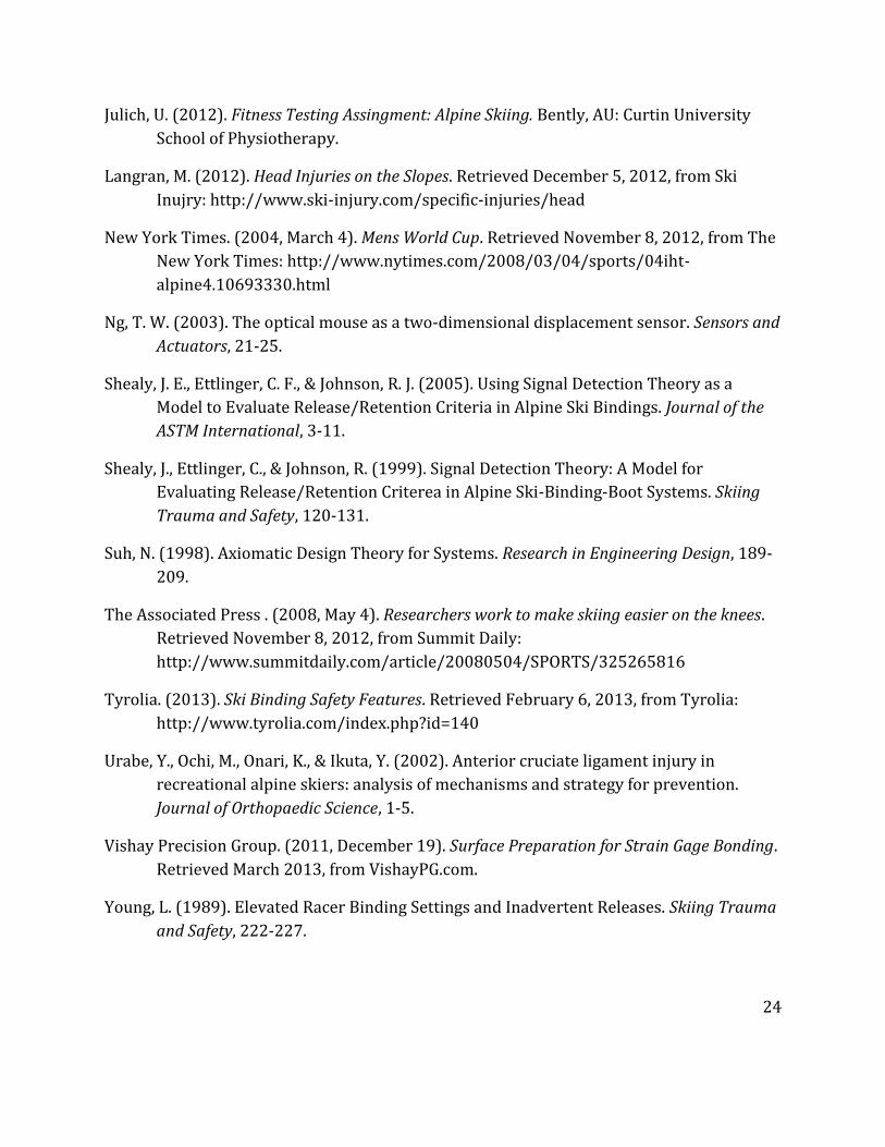
8. Appendix A Examples of release and retention failures
One example of the ratchet effect is illustrated in Matthias Lanzinger’s world cup super-
giant slalom crash on March 2nd, 2008. During this crash Lanzinger sustained severe injury
to his lower left leg including open fracture of his tibia and fibula. His lower left leg was
amputated two days after the crash due to damage to the circulatory system and prolonged
ischemia of the lower leg (New York Times, 2004). It is probable that the non-release of the
vertical heel release mechanism, as shown in Figures 1 and 2, caused the initial fracture.
Once broken, the fractured leg did not provide the resistance needed for lateral toe release,
which is why twisting well beyond the normal range of motion between figures 2 and 3 can
be seen. World Cup skiers’ bindings are often set to extraordinarily high release settings to
avoid inadvertent release, which can thus influence extremely severe LEER injuries.
Figure one: Lanzinger braces
for impact with gate after
coming off a jump in the
wrong direction, the impact
causes the fall.
Figure two: The left ski
makes contact with the snow
and forward bending
moment is applied to lower
leg. The binding fails to
release, causing a severe
tibia-fibula boot top fracture.
Figure three: With no
resistance offered by the
broken leg, the foot rotates a
full 180°. This leads to
massive internal bleeding
and later requires the
amputation of the lower leg.
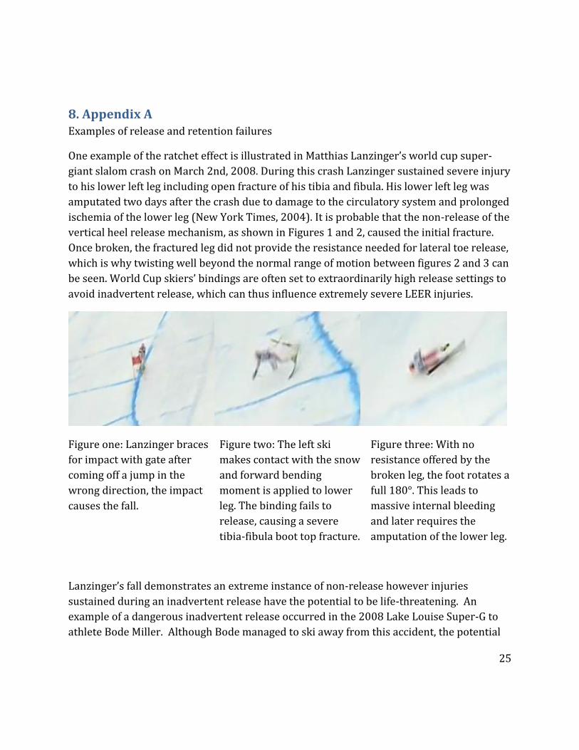
Lanzinger’s fall demonstrates an extreme instance of non-release however injuries
sustained during an inadvertent release have the potential to be life-threatening. An
example of a dangerous inadvertent release occurred in the 2008 Lake Louise Super-G to
athlete Bode Miller. Although Bode managed to ski away from this accident, the potential
26
for sever upper body injury during a high speed inadvertent release like this is very high.
The inadvertent release was likely caused by a vertical heel release because the released
binding apparently has the heel piece in the down position. In one study, vertical heel
inadvertent releases such as this were self-reported as more common in giant slalom and
speed events, and is purportedly caused by two mechanisms; Brown’s Bow, or a sudden
unweighting of the ski (Young, 1989).