
TO - Defense Technical Information Center · VI. References 6-1. LIST OF ILLUSTRATIONS Figure Page...
47
UNCLASSIFIED AD NUMBER AD808504 NEW LIMITATION CHANGE TO Approved for public release, distribution unlimited FROM Distribution authorized to U.S. Gov't. agencies and their contractors; Administrative/Operational Use; Jan 1967. Other requests shall be referred to Rome Air development Center, Griffiss AFB, NY 13441-5700. AUTHORITY RADC, USAF ltr, 9 Jul 1975 THIS PAGE IS UNCLASSIFIED
Transcript of TO - Defense Technical Information Center · VI. References 6-1. LIST OF ILLUSTRATIONS Figure Page...

UNCLASSIFIED
AD NUMBER
AD808504
NEW LIMITATION CHANGE
TOApproved for public release, distributionunlimited
FROMDistribution authorized to U.S. Gov't.agencies and their contractors;Administrative/Operational Use; Jan 1967.Other requests shall be referred to RomeAir development Center, Griffiss AFB, NY13441-5700.
AUTHORITY
RADC, USAF ltr, 9 Jul 1975
THIS PAGE IS UNCLASSIFIED

RADC-TR- 66-708Interim Report
PREFERRED-CIRCUIT TECHNIQUES FOR VARACTOR -TUNED FILT ERS
00 Solomon HechtGerald Kannischok
Airborne Instrument Lab
TECHNICAL REPORT NO. RADC-TR*- 66-708
January 1967
This document is subject to specialexport controls and each transmittalto foreign governments, foreign na-tionals or representatives thereto maybe made only with prior approval ofRADC (EMLI), GAP13, N.Y. 13440
Rome Air Development CenterResearch and Technology Division
Air Force Systems CommandGriffiss Air Force Base, New York

PREF ERRED-CIRCU!T TECHNIQUES FOR VARACTOR-TUNED FILTERS
Solomon HechtGerald Kannischak
Airborne Instrument Lob
This document is subject to specialexport controls and each transmittalto foreign governments, foreign na-tionals or representatives thereto maybe made only with prior approval ofRADC (EMLI), GAFS, N V. 13440

FOREWORD
This report was prepared by the Special Systems and Tech-
niques Department of Airborne Instruments Laboratory (AIL) under
Contract AF 30(602)-3583, Project 4540, Task No. 454002, for Rome
Air Development Center. The AIL report number is 5591-TDR-5.
The work was performed by Mr. Solomon Hecht under the
direction of Mr. Stanley Becker, Section Head, and Mr. Gerald Kanischak,
Group Leader.
The RADC Project Engineer was Mr. Hollis J. Hewitt,
EMCVI-1.
Document contains information embargoed from release to Sino-
Soviet Bloc Countries by AFF hOO-I0, "Strategic Trade Control Program."
This report has been reviewed and is approved.
Approved: iz'.,HOLLIS V hiJ4ITTInterf Anal & Control SecVulnerability Reduction Branch
Appoe:4
Chief, Vuinerabiity Reduction BrCommunicaLions Divisior
iii
ABSTRACT
This report describes an investigation of circuit techniquesto minimize spurious reponses in varactor-tuned filters.
Desi&n equations for the center frequency, bandwidth andinsertion loss of single and multiple-resonator filters are presented.
Series-resonant filters with one and two resonators were constructedand measurements of their performance characteristics were made.
Measurements of the spurious response characteristics of the single-
resonator filter were also made.
One- and two-resonator filters were also constructed using
a pair of opposingly biased varactors (push-pull circuit) for each reso-
nator. Measurements show that such a circuit can significantly reduce
the second-harmonic generation and the response to a signal at one half
the tuned frequency.
iii/iv

TABLE OF CONTENTS
PageAbstract
iii/iv
Introduction 1-1
I. Design 2-1
A. Properties of Series and Parallel Resonant 2-1Circuits
B. Design of Single-Resonato:- Varactor-Tuned 2-5Filters
C. A Design of Multiresonator Varactor-Tuned 2-8Filters
D. Bias Circuit Design 2-10III. Experimental Circuits 3-1
A. Single-Resonator Varactor-Tuned Filter 3-1B. Two-Resonator Varactor-Tuned Filter 3-1
IV. RFI Properties of Varactor-Tuned Filters 4-1
A. Measurement Setup and Procedures 4-1B. RFI Measurements of Single-Resonator Filter 4-4C. Single-Resonator Filter Using Opposingly 4-11Biased Varactors Connected in ParallelD. Two-Resonator Filter Using Opposingly Biased 4-17
Varactors Connected in ParallelV. Conclusions
5-1
VI. References 6-1

LIST OF ILLUSTRATIONS
Figure Page
1 Parallel-Tuned Resonant Circuit 2-1
2 Series-Tuned Resonant Circuit 2-4
3 Single-Resonator Tunable Filter 2-6
4 Transformer Equivalent Circuits 2-8
5 Multiresonator Tunable Filter 2-9
6 Experimental Single-Resonator Tunable Filter 3-27 Electrical Characteristics of Single-Resonator 3-3
Tunable Filter
8 Experimental Two-Resonator Tunable Filter 3-3
9 Electrical Characteristics of Two-Resonator Tunable 3-4Filter
10 Test Setup for Second Harmonic Measurements on 4-2Tunable Filters
11 Test Setup for Third-Order Intermodulation Meas- 4-2urements on Tunable Filter
12 Test Setup for Cross-Modulation Measurements on 4-3Tunable Filter
13 Test Setup for Dynamic Range Measurements on 4-4Tunable Filter
14 Third-Order Intermodulation Output vs Filter Input 4-5Levels for Single-Resonator Varactor-Tuned Filter
15 Second Harmonic Output vs Fundamental Input Level 4-6for Single-Resonator Varactor-Tuned Filter
16 Second Harmonic Output vs Fundamental Input Level 4-7for Single -Resonator Varactor-Tuned Filter
17 Input-Output Characteristics as a Function of DC 4-8Bias for Single-Resonator Varactor-Tuned Filter
18 Cross-Modulation Ratio vs Interfering Signal Level 4-9for Single-Resonator Varactor-Tuned Filter
19 Single-Resonator Filter Using Opposingly Biased 4-12Varactors Connected in Parallel
20 Electrical Characteristics of Single-Resonator 4-13Filter Using Opposingly Biased Varactors Connec-ted in Parallel
v1

Figure
21 Third-Order Intermodulation Output vs Filter Input 4-14Levels for Single- Resonator Varactor-Tuned FilterUsing Opposingly Biased Varactors Connected inParallel
22 Input-Output Characteristics as a Function of DC 4-15Bias for Single-Resonator Varactor-Tuned FilterUsing Opposingly Biased Varactors Connected inPa rallel
23 Second Harmonic Output vs Fundamental Level for 4-16Single- Resonator Varactor-Tuned Filter Using Op-posingly Biased Varactors Connected in Parallel
24 Electrical Characteristics of Two-Resonator Filter 4-17Using Opposingly biased Varactors Connected inParallel
25 Third-Order Intermodulation Output vs Filter Input 4-18Levels for Two-Resonator Varactor-Tuned FilterUsing Opposingly Biased Varactors Connected inParallel
viij /Vi ii
k.

F
I. INTRODUCTION
This report describes the work performed to study interfer-
ence effects ii varactor-tuned filters for receiver applications, The
study also provides circuit techniques which are useful in reducing in-
terference susceptibility to interfering signals.
The design of electronically tunable filters is usually accom-
plished by using a varactor or a YIG as the tuning element. The YIG
however, is only practical at microwave frequencies, and consequently
the varactor is used in electronic tuning applications up to UHF. As-
sociated with varactor-tuned filters are interference properties result-
ing from the nonlinear characteristics of the varactor. In particular,
properties such as harmonic generation, intermodulation, cross modu-
lation, detuning and osciulations arise. When a filter of this type is
used as an RF preselector for a receiver, these interference properties
can seriously degrade the receiver performance. Therefore, it is im-
portant to eliminate or to at least reduce these unwanted properties, in
order to make the voractor-tuned filter a useful receiver component.
This report evaluates the series- and parallel-resonant cir-
cuit, ani shows the advantage of the series-resonant circuit. Design
equation.; are presented for the center frequency! bandwidth, and inser-
tion loss of the single-resonator filter. These equations are then gen-
eralized for the multiresonator filter.
Measurements were made to determine the intermodulation
and cross-modulation properties of the varactor tuned fiiter. A varactor
filter was then constructed using a pair of opposingly-biased varactors
(analogous to a push-pull circuit). Measurements show that the latter
circuit had reduced susceptibility to even-order intermodulation.
3-1/1-2

II. DESIGN
A. PROPERTIES OF SERIES AND PARALLEL RESONANT
CIRCUITS
We now consider the two basic resonant circuits, the series
and the parallel RLC circuits. Either circuit can be used as a filter
element and we must therefore, choose whichever configuration is most
applicable for our design. The properties that are of interest are varia-
tion of bandwidth and insertion loss as a function of center frequency.
Generally, constant bandwidth and constant insertion loss over the tun-
ing range are desirable.
1. PARALLEL RLC TUNED CIRCUIT
The varactor-tuned parallel RLC circuit is shown in Fig-
ure 1A.
-0LR L RV0O V C R L
AB
FIGURE 1. PARALLEL-TUNED RESONANT CIRCUIT
Using the equivalent circuit for the varactor, the circuit in Figure lA
can be approximated by the circuit shown in Figure IB where
R1 = varactor scries resistance
Qv = varactor quality factor R vC
The center frequency of this circuit is given by:
1 _fo =-27T V LC

With Cmax and Cmi, the maximum and minimum capacitance values
respectively, the center frequency can be varied from fmin to fmax
where
m 2v max max L
The tuning range is the ratio of the maximum to minimum frequency.
Thus,
t1
f max Fcmaxl~min =LminJ
The 3-db bandwidth of a resonant circuit is given by
fof3db - Q
where QL is the circuit loaded-Q given by
R2
R vQv RL
2
When high-Q varactors and low impedance loads are used, R R
and the expression for the loaded Q reduces to
RL
QL =
2-2

The bandwidth therefore, is given by
23 db 2 fL
and is seen to be proportional to the square of the center frequency.
The insertion loss for a single resonator is given by
I.L. indb =20 log - 20og 1QQL
Since
RLQL -oL
W
and the unloaded circuit Q, Qu, is given by
2Rv Q
then,
L RL RL WoLRL RLL 2
7 3R 3 2 3
v V vo VO V

Thus, the insertion loss as a function of frequency is given by
I.L. indb =20 log 1 ]2R LL 2
L Rv 0 j
2. SERIES RLC TUNED CIRCUIT
The varactor-tuned series RLC circuit is shown, in Figure 2A,
and the equivalent circuit is shown in Figure 2B.
L R L L R V C RL
4 B0
FIGURE 2. SERIES-TUNED RESONANT CIRCUIT
The center frequency and tuning range are the same as for
the parallel circuit.
The 3-db bandwidth is given by fo/QL , but QL has a different
value now. It is given by
w0L
QL -RL + Rv
and can be approximated by= O_
QL MRL
for high-Q varactors.
The expression for the 3-db bandwidth, then reduces to
foRL RL
f3 db woL 2trLconstnt
2-4

Thus, it is seen that the bandwidth does not change with variation in
center frequency.
The insertion loss is given by
1
I.L. =db =20log Q
0LQL RL Rv =- constant
C 'oL, RLR v
Thus, it is seen that the insertion loss remains constant as a function
of center frequency and equal to
I.L. =db =20log R
L
Thus, for varactor-tuned filters the series-tuned RLC circuit is ideal.
It exhibits constant bandwidth and constant insertion loss over the tuning
range.
B. DESIGN OF SINGLE-RESONATOR VARACTOR-TUNEDFILTERS
The equations for a single-resonator varactor-tuned filter
will now be derived for a series-tuned circuit with transformer (or mag-
netic) coupling to the source and load. Capacitive coupling to the source
and load is not recommended because the additional capacitance reduces
the tuning range of the :ilter.
-'-5

The schematic of the filter is shown in Figure 3A.
K K
P
L L
cL 20"1 LAR
L. 2 2L~-O(
A + R C 2(1 - K2)L
K
C
FIGURE 3. SINGLE -RESONATOR TUNABLE FILTER
where
R = source and load impedances,
L = secondary inductance,
a = factor that relates the primary inductance to thesecondary inductance,
K = coefficient of coupling of the transformer.
Using the varactor equivalent circuit and the "T" equivalent for the
transformer, the circuit takes the form shown in Figure 3B. By means
of Thevenin's theorem, and assuming that (o aLR) ' 1, we can further0
2-o

reduce the circuit to that shown in Figure 3C. From this circuit, we
see that the center frequency is given by
1
and the 3-db bandwidth is given by
2RK 2 + a Rf 3 db2
4waL (1 - K2)
Given a particular varactor and the specifications on the filter, the only
unknowns remaining to be solved are a, K, and L. There are many sets
of values for a, K, and L that will result in the desired filter response,
and therefore, a third equation is necessary to establish the design. One
logical solution would be to design for a particular insertion loss using
the equation:
2RK2 +aR
I.L. in db =20 log 2 + aK2 R
Another solution would be to minimize the number of components required
to construct the filter when the equivalent T's are used for the trans-
formers. (U;ing equivalent T's to replace tranbl'ormers in the filter
circuit is advantageous because it eliminates the required control of
mutual coupling between the primary and secondary of the transformer.)
Looking at the relationship of Figure 4, we see that by making K2 = 1/a,
we can eliminate one of the inductors from tht equivalent T transformer.
In the design of our filter we used minimum-component
equivalent T transformers to simplify the design.
I

K L - KL/., L - KL,,' L.a - I)
K2
*
aL L 4 KL,/ L
FIGURE 4. TRANSFORMER EQUIVALENT CIRCUITS
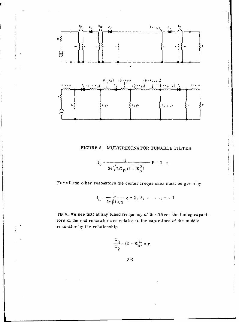
C. A DESIGN OF MULTIRESONATOR VARACTOR-TUNEDFILTERS
When multiresonator filters have to be designed a particularlyuseful approach is to use the equal-element filter design (reference 1).
The reason for this is that only two voltages are required to tune the fil-ter. One voltage would vary the center frequency of all but the first and
last resonator and the other would vary center frequency of the first and
last resonator. A Eutterworth or Tchebycheff design would require a
voltage for every pair of resonators.
The circuit for an arbitrary number of resonators is shown
in Figure 5. Since in an equal-element design the filter response is
completely specified by (1) the decrements, (2) the inter-resonatorcoupling and (3) the unloaded Q of the resonators, we shall determine
these parameters and obtain design equations. The equivalent circuitof the circuit in Figure 5A with the condition that K2 = a is shown inFigure 5B. The decrement, d, is found by detuning the second resonatorand finding the reciprocal of the Q of the equivalent input network. It can
be shown that
1 +RK4
QL w0L (2 - Ko)
It can also be shown that the end resonators have a center frequency
given by
2-8
S K 1 1 z ' , K 0
OL L L L L L L oLR
A
L(I K,2) L (I K2 3) L11 K, fl
Lo 1) C I L(I-K 12 ) 4 C~ 2 L(I-K,,)' 4 ( K _,. Cn L.(4-
L K12 L X2 3 L J K , L R
FIGURE 5. MULTIRESONATOR TUNABLE FILTER
2?r1VLC P (2- K 0)
For all the other resonators the center frequencies must be given by
fo q =2, 3, --- ni
Thus, we see that at any tuned frequency of the filter, the tuning capaci-tors of the end resonator are related to the capacitors of the middleresonator by the relationship
-4 (2 K K2 ) rC 0
p
2-9

The inter-resonator coupling coefficients K1 2 through
K- n are all related to K, which by definition is given by
K =d -d0
It can be shown (reference 1) that
K 1 2 =K23-- - Kn - 1, n =2K = 2(d- do )
We now have four definitive equations
Rv + RK o4
4%L (2 -K 2 )
1fo = -.21H LCp (2 - K)
-CA (2 K- Rp
K12 =--- --------- K. 1,n =2(d - d0 )
Summarizing, for a particular varactor with capacitance
Cp and given filter specifications of center frequency, bandwidth and
tuning range, the unknowns to be solved for are Ko; K12; - - -; K n _ 1, n;
L and C q. With the four definitive equations given above these unknowns
can readily be solved.
D. BIAS CIRCUIT DESIGN
The bias circuit, which must provide the DC tuning voltage
for the var.ctor, is essentially simple. The impedance looking into the
bias circuit must be high at all frequencies that the filter must iune to.
2-10

Fi
Since tuning is accomplished by varying the bias voltage at some finiterate (say a sawtooth) the bias circuit must also be a low impedance for
the tuning signal rate. If the highest frequency component of the tuning
signal approaches the lowest filter frequency, then a simple RF choke
and bypass capacitor will not be adequate and a more elaborate decoupling
filter nmust be used.
Another consideration for the bias circuit is that the bias
resistor should be kept small. Large resistors can cause a kind of re-
laxation oscillation to develop in the bias circuit when the signal voltage
is large and the bias voltage is small. Under this condition, the signal
becomes modulated at a frequency determined by the bias resistor and
the bypass capacitor. Such oscillations have been observed with resistors
as small as 10 k when the varactor is biased near zero volt and the signal
level is above 0 dbm. If the oscillation is present, increasing the size
of the bypass capacitor only reduces the oscillation (or modulation) fre-
quency.
2-1112-12

III. E7.PERIMENTAL CIRCUITS
A. SINGLE-RESONAI OR VARACTOR-TUNED FILTER
A single-resonator varactor-tuned filter was designed
using the equations derived in Section II-B. The varactor used in this
circuit was a High-Q Varicap made by TRW Semiconductors. The
varactor parameters are as follows:
Cat -4 v 14.4 pf
Q at 50 MHz 360
Breakdown voltage -87 volts
The filter was designed for a center frequency of 60 MHz and a 2-MHz
3-db bandwidth when the varactor capacitance is 14. 4 pf. The resulting
design is shown in Figure 6A. The complete circuit, including the
biasing network is shown in Figure 6B. The electrical characteristics
of this filter are shown in Figure 7.
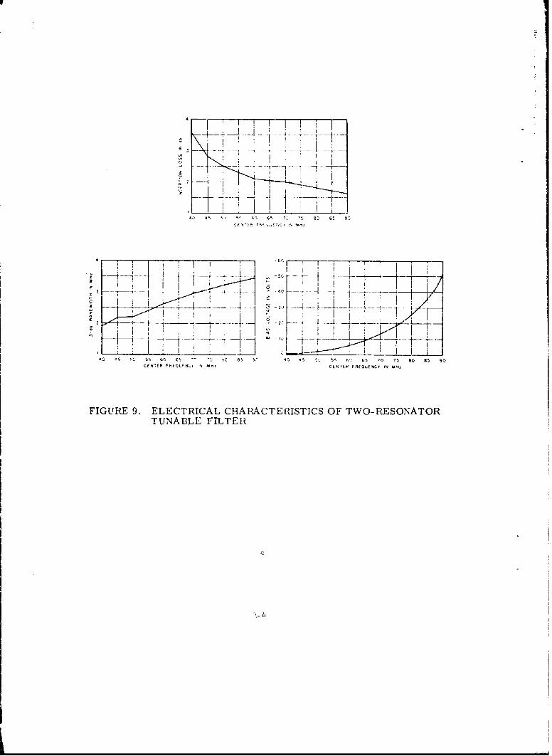
B. TWO-RESONATOR VARACTOR-TUNED FILTER
A two-resonator varactor-tuned filter was designed using
the equations derived in Section II-C. The varactors used in this cir-
cuit were matchcd Varicaps with the following characteristics:
Varactor 1 Varactor 2
C at -4 v 15.96 pf 15.96 pf
Q at 50 MHz !, 300 ,300
Breakdown voltage 50 v 50 v
3-.

The filter was also designed for a center frequency of 60 MHz and a
2-MHz bandwidth when the varactor capacitance is at 14. 4 pf. The
resulting design, including the DC biasing network, is shown in Fig-
ure 8. The electrical characteristics of this filter are shown in
Figure 9.
1.04 UH 1.04 UH
50 OHMS
0.32 UH 0.32 UH 50 OHNS
A
0.1 UF
1-04 UN OOO PF RFC 1,04 UH
50 OHMSC
0.32 UH 0.32 UN 50 OHMS
FIGURE 6. EXPERIMENTAL SINGLE-RESONATOR TUNABLEFILTER
3-2

00
till
-4
I I
. /I l II ! .p . '
S --T -- f
4 5 5c 55 I 5 70 15 30 85 so 40 ' 5 45 70 ?5 so 95 to
zl IF
TNTt 0!£QLLNCY -I IT,
---x ~Ih i Ii.IVK]-i II -- 1 -
I I I"-.. I -4__j _! I 0 I - -I
.". UK 0 .2 '-d, -L- - .,78-'
-I , .
___, I E ! .
i 45 50 55 00 6i 70 '5 30 £5 50 40 '5 50I 55 £0 0$ 70 75 40 05 0
CENTER F £EQjKhCY" IN Uillz CENTd R FNCLJ(UNCY IN il'l!
- FIGURE 7. ELECTRICAL CHARACTERISTICS OF SINGLE-
RESONATOR TUNABLE FILTER
3-3
I.*,8l UN .27 UN4 070 I, .507 UN
FIGURE 8. EXPERIMVENTAL TWO-RESONATOR TUNABLE FILJTER
!~~ ........ iI . I ; ! .I I
4, 5 5.. 54 63 65 U S 4 8
I 2
___ 4 4 1t0 5 5 61 6 65 J 4a 4~ 5 6 65 '0 75 90 85 90
C(I. FP666 L 4.I M- CE TE 6 . 4.-- ENCY i4 M4,
FIGURE 9. ELECTRICAL CHARACTERISTICS OF TWO-RESONATORTUNABLE FILTER
_JI

IV. RFI PROPERTIES OF VARACTOR-TUNED FILTERS
Several i.nterference properties associated with varactor-
tuned filters were investigated. Harmonic generation, particularly
the second harmonic, is of importance for filters with tuning ranges
of two to one or more. Fo; such filters, the second harmonic of an
input signal can appear within the tuning range, and if it is not sup-
pressed properly, the harmonic becomes an erroneous signal. Per-
haps of even greater importance is the third-order intermodulation
product. This effect is very significant because it can occur at any
frequency that the filter is tuned to. Other effects, such as cross
modulation and detuning, can also occur and were investigated.
A. MEASUREMENT SETUP AND PROCEDURES
1. SECOND HARMONIC MEASUREMENT
The setup used to make harmonic measurements is shown
in Figure 10. With the signal generator tuned to frequency f0 1 the sig-
nal is passed through the low-pass filter to attenuate the second har-
monic of the generator. Now witn fo being the only significant signal
frequency appearing at the filter input, the second harmonic of f0 gen-
erated in the filter can be measured. The output of the filter ":s fed
through a narrow band-pass filter so that the fundamental frequency
does not appear at the input of the receiver. By calibrating the re-
ceiver, the level of the second harmonic can be obtained.
2. THIRD-ORDER INTERMODULATION MEASUREMENT
The setup used to make third-order intermodulation meas-
urements is shown in Figure 11. With the filter tuned to fof the two
signal generator frequencies (fI and f2 ) are selected such that 2f 1 - f2
f The two signals (f1 and f2 ) are combined in the summing network
and fed into the filter. Due to the nonlinear characieristics of thr fil-
ter, a signal results at f0 that is then fed into a very s-lective filter,

A
OA, FIGUE10 ETETU AO SCN D ARMONI
T ARFILTOR TEST1 1 TE
OC BIAS
FIGURE 0. TEST SETUP FOR HIRDORDEHRMONjA~ID
LAIMEASUREMENTS ON TUNABLE FLTER
SIGNALJ 0-202

which rejects the frequencies fl and f2' The level of the third-order
intermodulation product at f is then measured wi the receiver.
3. CROSS-MODULATION MEASUREMENT
The test setup used to make cross modulation-measure-
ments is shown in Figure 12. With signal generator no. 1 modulated
to 100 percent by a 1-kHz signal and with signal generator no. 2 off,
a reference corresponding to 100 percent cross modulation is obtain-
ed on the SWR indicator. The modulation is then removed from sig-
nal genc tor no. 1 resulting in a CW input at fl into the filter. Sig-
nal generator no. 2 is now turned on and 100 percent modulated at
1 kHz. This signal is also fed into the filter under test. The output
of the filter is then passed through a narrow band-pass filter tuned to
f arid the 1-kHz modulation that is now present on the originally un-
modulated signal is detected and read on the SWR indicator. The dif-
ference between the two readings obtained on the on the SWR indicator
in db denotes how much modulation with respect to a 100 percent mod-
ulated signal is present on the desired CW signal and is called the
SI A 0 0- 2C do.. ENERAT)P ST _p - ]AT I, AT T ENUATCIR r
FIGUE~r1.TS T U FOR, : :TE- 6-dT BE-NU-PASSURM T~UO A DER TES F;LTER
,jE ATC IPEAT f2 A!LUA TOP DE 'TEC TOP
INDICATOR
FIGURE 12. TEST SETUP .FOR CROSS,-MODULATION MEAS-UREMENTS ON TUNABLE FILTER

cross-modulation ratio. The cross-modulation ratio M is defined by
the equation
M = 10 log M k
where
Mk = cross-modulation index--that is, the modulation index
appearing on the desired signal
M i = modulation index of the interfering signal
4. DYNAMIC RANGE OR DETUNING MEASUREMENT
The test setup used to make this measurement is shown
in Figure 13. The measurement consists of feeding a signal at the
frequency that the filter is tuned to and recording the output level of
the filter. As the input signal level is increased, the average capa-
citance value of the varactor decreases causing the center frequencyof the filter to increase. This effect results in an increased trans-
mission loss through the filter since the signal is now on the skirt of
the filter selectivity characteristic. Thus, by plotting an input-out-
put characteristic, a saturation or limiting effect can be observed.
C.NA O-2O0 3,133W3 O
a ' 75 A T 'E 3 , & T O ,,
FIGURE 13. TEST SETUP FOR DYNAMIC RANGE MEAS-UREMENTS ON TUNABLE FILTER
B. RFI MEASUREMENTS OF SINGLE-RESONATOR FILTER
The measurements described in Section IV-A were made
on the single-resonator filter described in Section I-B. The results
are shown in Figures 14, 15, 16, 17, and 18.
4-I4

r
-30 ___ _E
S-.40
FILTER INPUT LEVEL AT
0
fILTER INPUT LEVEL AT*' 60 6 h,- b
70
0
FILTER INPUT LEVEL AT 64 Mz IN0 db%
FILTERINPERIUT LEVELS ATR S4UINGE REONTO
1. THIRD-ORDER INTERMODULATION
It can be seen from Figure 1i4 that an interinodulation prod-uct of -32. 5 dbmn can occur at 60 MHz when two interfering signals of0 dbm at 62 and 64 Milz are present. This fact, however, does notmake the filter useless, since in most receiver applications such high-level signals are rarely encountered.
From the expression relating third- order intermodulationoutput level to the input signal levels, we can predict w~hat the third-order intermodulation output would be for input levels of -20 dbm at62 and 64 MHz. The expression is
P P 1 2 P PI + 2P 2 + K 1 2
'4-5

where
P1 2 third-order intermodulation output level, in dbm
P1 input level at f in dbm
P2input level at f 2, in dbm
K12 constant depending on the device, in dbm
FiLTEA TUNIC TO INPvTFl IEOU(1f
20I1
30 ___
3 60
F10ERLNPO .N%1 .EYEC
FIGURE 15. SECOND HARMONIC OUTPUT VS FUNDA-MENTAL INPUT LEVEL FOR SINGLE-RESONATOR VAI1ACTOR-TUNED FILTER

-40
A -50 _ __
z
0
-j
u. -80 /
-90 -____ ____ _ _ _ _____
-24 -20 -16 -12 -8 -4 0
FILTER INPUT LEVEL AT 30 MHz IN dbm
.FIGURE 16. SECOND HARMONIC OUTPUT VS FUNDAMEN-TAL INPUT LEVEL FOR SINGLE-RESONATORVARACTOR-TUNED FILTER
From our measurements, made with both input signals at 0 dbm, we
have
-35.2 = 0 + 0 + K1 2
K1 2 = -32.5 dbni
Therefore
P1 2 = P1 +2 P2 -32.5
1-7
r0
-1-
' -200-
40___ VAAACTOR SIAS 5 V Dc ___
-40 -35 -30 -25 -20 -15 -10 -5 0
FILTER INPUT LEVEL IN db n
S-20____ __
- 40VwCO IS15VD
FREQ2UENCY 50MNE
FILTER INPUT "'"EL IN dbn.
0
-10
-40 ____VARACTOR SIAS 0,7 V DCFREQUENCY 45.5 MHz
-50111-40 -35 -30 -25 -20 -IS -10 -5 0
FILTER INPUT LEVEL IN dbY
FIGURE 17. INPUT-OUTPUT CHARACTERISTICS AS A ]FUNC-TION OF DC BIAS FOR SINGLE -RESONATORVARACTOR-TUNED FILTER

I
For input levels of -20 dbm
P1 2 =-20 -40- 32.5 -92.5 dbm
Thus, we see that for two input signals at 62 and 64 MHz of -20 dbm
each, the third-order intermodulation output level is -92.5 dbin.Under such conditions, operation of the filter as a preselector ispossible. If lower third-order internodulation levels are required,
either narrower bandwidth or additional resonators should be usedto attenuate the interfering signals and thereby reducing the inter-modulation levei.
AI
W U AT ON A
4-
I I
Io I
I
IOt5,REO S.GMAL. -204h Al jOSH.
- ZA -20 ,6 -, 0 -
FIGURE 18. CROSS-MODULATION RATIO VS INTERFERINGSIGNAL LEVEL FOR SINGLE- RESONATORVARACTOR- TUNED FILTER
4-9
2. SECOND HARMONIC
Figure 15 shows the level of the generated second har-
monic occurring at the output of the filter as a function of the funda-
mental frequency input power level. The measurements were per-
formed for input frequencies of 50, 60 and 70 MHz with the filtertuned to these frequencies. The output frequencies were 100, 120,
and 140 MHz, respectively. It ,s seen that for input levels on the
order of 0 dbm at 60 Mhz,. a harmonic level of -20 dbm can occur
at 120 MHz. In superheterodyne receiver applications, the serious-
ness of generating a second harmonic will depend upon the specificfrequency relationships between the RF, IF and LO frequencies.
For example, consider an up-converter where the IF is at 235 MHz
and the LO is at 175 Mdz (for an RF at 60 MHz). The second har-
monic of the RF mixing with the second harmonic of the local oscil-
lator produces an output at 230 MHz, which may well be in the IF
pass band. If we have an IF of 10 MHz with an LO at 50 MHz, then
the 120 MHz (second harmonic) produces an output at 70 MHz with the
fundamental of the L() and at 20 MHz with the second harmonic of the
LO. Thus, for the IF at 10 MHz, the spurious response is at twicethe IF and should not be a problem.
The filter property that is of more concern is the second
harmonic level occurring at the center frequency of the filter when a
signal, whose frequency is one half of the filter center frequency, is
applied at the input of the filter. This measurement was made with
the filter centered at 60 MHz and the result is shown in Figure 16.
From this curve, it is seen that the generated output increases pro-
portionally as a function of the input reaching a maximum of -47 dbm
for an input level of 0 dbm.
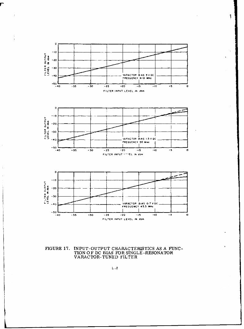
3. DYNAMIC RANGE OR DETUNING
Figure 17 shows input-output characteristics of the filter
for DC bias voltages of 0.7, 1. 5, and 5. 0 volts applied to the varactor.
It can be seen that with 0. 7 volt bias on the varactor, a signal whose
4_10

level is 0 dbm detunes the filter so that the signal appears on the skirt
at approximately the lower 5-db point. With higher DC bias, the de-
tuning decreases and it can be seen that with 5 volts bias, linear opera-
tion of the filter is obtained up to at least 0 dbm input signals. It is,
therefore, advantageous to operate at higher bias-voltage levels when
large signals are expected to be fed into the filter.
4. CROSS MODULATION
Figure 18 shows the cross-modulation ratio for the filter
when a midband 60-MHz desired signal of -20 dbni and a 62-MHz inter-
fering signal modulated to 100 percent with a 1-kHz signal are applied
to the filter. With a 0-dbm interfering signal, the cross modulation is
approximately 10 percent.
C. SINGLE-RESONATOR FILTER USING OPPOSINGLY BIASED
VARACTORS CONNECTED IN PARALLEL
By using a pair of opposingly-biased matched-varactor
diodes connected in parallel as shown in Figure 19A, a composite even
functioned capacitance versus signal voltage characteristic as shown
in Figure 19B is obtained. 3y performing the operations
Q- fCiv) dv
and
i(t)
IL can be shown (reference 2) that the resulting Fourier Series expres-sion for the current through the diode contains only odd harmonics of
the input frequency. Thus, by using this diode configuration in the
filter, the second harmonic response may be entirely eliminated.
k4 -ll
I1

ry
IRFC
OUF C U
A
-E C '
-EIN C E INSIGNAL VOLTAGE
a
FIGURE 19. SINGLE-RESONATLOR FILTER USING OPPO-SINGLY BIASED VARACTORS CONNECTEDIN PARALLEL
This diode configuration was used in the single-resonator
filter for evaluation. The configuration consisted of two similar diodes
with nearly the same characteristics as the diode previously used.
Since the total capacitance in the resonant circuit is now doubled, it
is expected that the minimum and maximum frequencies of the tuning
range will be reduced by a factor of 1. 41. The characteristics of the
filter are shown in Figure 20.
4-12

44
60 4 iIo I " -
_40i i , , 0,
0 - .
2 0 -.-, I , /
0
20 0 40 $0 60 70 80 93 I00 l '5 40 4- 50 55 60 65 70 ?5
CENTER FREQUENCY IN Maz CENTRe FR QUENCY IN MAm
C ' I
C 10 35 4_^ 45 5 10 5! 6 0 6 7 0 75
CENrTER FREQUENCY IN 4Hz
FIGURE 20. ELECTRICAL CHARACTERISTICS OF SINGLE-RESONATOR FILTER USING OPPOSINGLYBIASED VARACIORS CONNECTED IN PARALLEL
A direct comparison of the intermodulation curves of Fig-
ure 21 to the curves of Figure 14 cannot be made since the varactor
voltage is different for each filter and the third-order intermodulation
level is related to the operating point of the diode. However, if the
operating points were the same, a 3-db ii-aprovement in third-order
intermodulation (3-db lower) would result from the use of two diodes
since each diode handles only half of the power. The improvement
in third-order intermodulation that we obtained by the use of two
4- 11

diodes is approximately 10 db, which tells us that the operating point
of this filter when tuned to 60 MHz was such as to produce approxi-
mately 7-db lower third-order intermodulation power than the opera-
ting point of the single-diode filter when tuned to 60 MHz. In any case,
there is a moderate improvement in third-order intermodulation when
the opposingly-biased parallel varactors are used.
-40 - ,
50FILTER INPUT LEVELAT 62 MHZ, Q dbm
FILTER INPUT LEVEL
_,0.
FILTER LEVEL EVE
AT- AT6 MM
4 -2_ -4 -20 -16 -12 A -, 0
FILTER INPUT LEVEL AT 64 MHz IN dbrn
FIGURE 21. THIRD-ORDER INTERMODULATION OUTPUT VSFILTER INPUT LEVELS FOR SINGLE-RESONA-TOR VARACTOR-TUNED FILTER USING OPPO-SINGLY BIASED VARACTORS CONNECTED INPARALLEL
From Figure 22, we can see that for bias voltages equiva-
lent to those used on the single diode filter, the "push-pull" filter has
a 3-db greater dynamic range.
Second harmonic r.ieasurements were made on the filter
with the test setup of Figure i0. The results are shown in Figure 23.
It can clearly be seen that there is a significant improvement in sec-
ond harmonic suppression when comparing these curves to those of
14 -..l1

II-20 __
020
FRQUNC 44
F,LTER INPUT LEVEL IN dbn,
-10 __
S-20
02
S-30__
____ 40___ VARACTOR SIAS 1.vDCFREQUENCY 34.2 MI-z
-50
FILTER INPUT LEVEL IN db
-101
LE

FILTER TUNED TO INPUT FREQUENCY
70 I
z FILTER INPUT FREQUENCY
0 50 MHz
0
I 9
o FILTER INPUT FREQUENCY60 MHt
0 0
FILTER INPUT FREQUENCY70 MHz
-110 1-20 -16 -12 -8 -4 0
FILTER INPUT LEVEL IN dbm
FIGURE 23. SECOND HARMONIC OUTPUT VS FUNDAMENTALLEVEL FOR SINGLE-RESONATOR VARACTOR-TUNEDFILTER USING OPPOSINGLY BIASED VARACTORSCONNECTED IN PARALLEL
Figure 15. Typically, at 60-MHz input frequency, the second har-
monic level is -82 dbm for a 0-dbrn input 12vel. The other filter hada seccnd harmonic level of -18 dbrn for 0-dbm input signal at 60 MHz.
With a signal at a frequency of one half the center frequen-
cy of the filter, the second harmonic could not be measured for input
levels as great as +7 dbm at 30 MHz. Since the sensitivity of the
measurement setup is -100 dbm, we can conclude that the second har-
monic of the input signal generated in the filter was at least 107 db
below the signal level.
4-16

D. TWO-RESONATOR FILTER USING OPPOSINGLY BIASEDVARACTORS CONNECTED IN PARALLEL
The two-pole filter described in Section III-B was modi-
fied to incorporate the parallel-diode configuration. The modified
filter characteristics are shown in Figure 24.
60 - -
050
o o - /- .
1 0
0 ""230 40 50 60 70 so so 100 30 35 40 45 50 5S 0 65 70 75
CENTER FREQUENCY 11N MHz CENTE.R FREQUEFNCY"
IN MHz
A 2
30 35 40 45 50 55 60 65 T0 75CENTER FREQUENCY IN MH2
FIGURE 24. ELECTRICAL CHARACTERISTICS OF TWO-RESONATOR FILTER USING OPPOSINGLYBIASED VARACTORS CONNECTED IN PARALLEL
With the filter tuned to 60 MHz, the generated second
harmonic of the 30-MHz input signal was smaller than -107 dbm forinput levels as high as +7 dbrn. 'Thus, we see again that second har-
monic suppression by means of opposingly biased varactors in paral-
lel can be readily obtained.
4-17

I
Third-order intermodulation measurements were alsomade in this filter and the results are shown in Figure 25.
_______ i___-40] __ _
z!o I--
WI-60
I -70ILTPUVEL FiLTER INPUT LEVEL INPUT LEEL
V
AT 62MMH,-Adbm1 Am AT 62 MMZ,-4dbm FILTER INPUI LEVEL
-80 1 1:-24 -22 -20 -16 -16 -14 -12 -10 -8 -6 -4 -2 0FILTER INPUT LEVEL AT 64 MM2 IN dbl.
FIGURE 25. THIRD-ORDER INTERMODULATION OUTPUT VSFILTER INPUT LEVELS FOR TWO-RESONATORVARACTOR-TUNED FILTER USING OPPOSINGLYBIASED VARACTORS CONNECTED IN PARALLEL
4-18

V. CONCLUSIONS
Voltage tunable filters using varactors as tuning elements
have been found to have good RFI characteristics at VHF when used
under the following restrictions:
1. The magnitude of the signal level should be smallerthan the DC bias voltage to maintain a linear input-output characteristic at the signal frequency.
2. The tuning range should cover no more than anoctave so that any generated second harmonic isout of the band of operation.
A typical application for a varactor-tuned filter which takes
these restrictions into account is that of a receiver preselector.
When it becomes necessary to tune the filter over more than
one octave, and it is required to minimize second harmonic generation,
the configuration employing two opposingly biased varactors connected
in parallel has been found particularly useful. Furthermore, this con-
figuration also provides an additional 3-db reduction in third-order
intermodulation for the same bias as compared to the single-diode con-
figuration.
RFI measurements were taken on a single-resonator filter
and a two-resonator filter, using a single varactor for each resonator.
Comparison measurements were taken on the same filters, using
opposingly biased varactors connected in parallel. A significant amount
of additional second harmonic rejection was obtained. An extention of
these results should apply to multiple-resonator filters.
5-1/5-2

I
V. CONCLUSIONS
Voltage tunable filters using varactors as tuning elements
have been found to have good RFI characteristics at VHIF when used
under the following restrictions:
1. The magnitude of the signal level should be smallerthan the DC bias voltage to maintain a linear input-output characteristic at the signal frequency.
2. The tuning range should cover no more than anoctave so that any generated second harmonic isout of the band of operation.
A typical application for a varactor-tuned filter which takes
these restrictions into account is that of a receiver preselector.
When it becomes necessary to tune the filter over more than
one octave, and it is required to minimize second harmonic generation,
the configuration employing two opposingly biased varactors connected
in parallel has been found particularly useful. Furthermore, this con-
figuration also provides an additional 3-db reduction in third-order
intermodulation for the same bias as compared to the single-diode con-
figuration.
RFI measurements were taken on a single-resonator filter
and a two-resonator filter, using a single varactor for each resonator.
Comparison measurements were takcn on the same filters, using
opposingly biased varactors connected in parallel. A significant amount
of additional second harmonic rejection was obtained. An extention of
these results should apply to multiple-resonator filters.
5-1/5-2

VL REFERENCES
1. J. J. Taub, "Design of Minimum Loss Band-Pass Filters,"Microwave Journal, November 1963.
2. W. R. Avellino, "Efficient Odd Harmonic Generation withOpposingly Biased Varactor Diodes," Proc IEEE, p 868-869,July 1964.
6-1/6-2

UnclassifiedSecft Classification
DOCUMENT CONTROL DATA .'R&D0~41ytv clasiefication .t file, body of abetrac and indexind annotation muat be ented when the overall report is clasailted)
I. OqIGINATING ACTIVITY (Coopm.te author) I. NEPORT 6CURITY C UASSIPICATION
Airborne Instrument Lab UnclassifiedFb GROUP
3. REPORT TITLE
Preferred-Circuit Techniques for Varactor-Tuned Filters
4. OSCRIPTIVE NOTES (Type of rport and Inclusive date@)
Interim Technical ReportS. AUTHOR(S) (Last name. time name. Initial)
Hecht, SolomonKannischak, Gerald
6. REPORT DATE 70. TOTAL NO. OF PAG |7 No. OF REPSJanuary 1967 54 2
SIa. CONTRACT OR GRANT NO. 90. ORIGINATOR-@ ftEPORT NUMUEr(S)
AF30(602)-3583.6. P11O0.1CT NO.
4540 b. &TKRkPONT NOS) (Any oth.rnbeat t at-may h o a.,.dIo r am~r
d. Task 454002 RADC-TR-66-708
10. AVA ILANILITY/LMITATION NOTICESThis document is subject to special export controls and each transmittal to foreigngovernments, foreign nationals or representatives thereto may be made only withprior approval of RADC (EMLI), GAFB, N.Y. 13440II. SUPPLEMENTARY NOTES 12. SPONSORING MILITARY ACTIVITY
None RADO (EMCVI-I)Griffiss AFB NY 13440
13. ABSTRACT
This report describes an investigation of circuit techniques to minimize spuriousresponses in varactor-tuned filters.
Design equations for the center frequency, bandwidth and insertion loss of singleand multiple-resonator filters are presented. Series-resonant filters with one andtwo resonators were constructed and measurements of their performance characteris-tics were made.
One- and two resonator filters were also constructed using a pair of opposinglybiased varactors (push-pull circuit) for each resonator. Measurements show thatsuch a circuit can significantly reduce the second-harmonic generation and theresponse to a signal at one half the tuned frequency.
DD oJAN64 1473 UnclasuifiodSecurity Clasuificaion

Security Classift an_______
14LINK. LINK 9 LINK C
LEOIn-~nl I ~ D 1 _____
1. ~ ~ ~ ~ ~ ~ Su rAGI AO~ Al%( ACIVT Ent- :htca,- dres -oe yscr)uigsadr
Ii Sta pote U-mucsents I b-r -P. Io
I. O RIIAINGl CTITY SIIANEnter the naevndad res iKpse by sebi-chifcto snotnaur staemths
0cr- with -ippro;r:ae seurty regulations. if3 'U S. Gov ernment agencies rosy obtin copies otthsrport ldrectil trr-DG te ulfe D
2hr DROOP- Automatic downgrading is specilied in DVD Di, users' shal reuest roogt het qalfidrnti2rSO. 0and Armed Forces todoseal Manua. Filter
ho i -ii.suna lso w-mn ppl.nicl -ho- that optio-l- ______________________
ars-~ ha- tivr used for Grup j an- Oru I anathr- o -,A. asa tht 4 "'U. S r-tirary agencies ntay obtais coptes of thise' reporit diretit from DDC- Other qualified userstREPORTr TITLEC Eter the complete repon Itl In alt. shalt request thriouphapIat feters Tirtl sin all oases shoul d b-! n unItas:ired-.
if a orn :f title - anul be, selected without clamsstCIot show- title classifrcation in all capitals is parenrhesis (h) :;A!' dintribotion of this repast is controlled. Qiad-iermvtd.atef foitowing the tite. red DUC users shall requesr through
I. rESCRIPTIVE NOTES If app-opr-ac, enter the type of ____________-___toprt g. ro etrr, etrisu. snrmatr . annual, or tinal. It the repon has been ura hed Ito the Office of Teoh~ia!
Ci~ ~ -ctnntai ae when a specIi rtportig period ios Servies, Department of Commerce. f-nt sumI t the pub! ii. indi-~i~td. -cute 'tris fact and enter the PiO. it knOwn.S.ATt~i Ene h aes fatoota hw t lit. SU:PPLEMENTARY NOTES: Woe far additionaf esplana-
or in rho report. E-nlet last same, lIst nme, middle inta. tr notes.If _.iar s-how rask en-I branch of se-ice. The name of or
they rincr 1 - -thuri a bslt esnto reqirement. - SPONSORING MII t ANY A(CIrVITY: Ester the same ofthi r.rrso fri-1 ofi.,e or! rig0py
6. RfI'OT Dft. Enter the lair of :hi- report as day, i .rifo ,e reseach and deoc;Ip i n. o acidans.
oIh' yar. or moth, pear. If n-- than one date appearsia hr report. use date of puhlication. I i ABSTRACT- Eator as absir- i Cret-- - , s fac tio
-7u TOTAL NUMUER OF PAGES The totalpaecon it .tr f ath api-uotscsuhcr- 5- bI t 1,r .I-,a ro-~ghouto ~ ~ ~ ~ ~ p i-tlas-etPiia in~o ~te ~.-eter heii part- if addi.,na. paice is req.racoinaotshtsu!
osier ifDaies ... ofairirtig of-0 0be attac hod
- --NuMtat-R OF REFEPUF'NCES Enter the tial somber ot II Iis hil dos-trhe that tHe airattaci i..-.t if t;-rofetenoos. cie h on eaoafied Each Paragraph .- 'he ah-r.I t -hal o t
MaL CONTRC OR GRANT Nt'MLER. it ippro-riare. este- as toid:-ta of the m-].ra0 - sevarz of !tie inthe a .. k ~i numftierof the -1-:toLI -rgant under' which tfortoatron in the paragraph. reprt se-- JC; ,,r I,,W
the repo -a writen Tb -c is no ;inrilice us the I, nei of L-r ssiia~ oHoo-
8b. f.; & 8sf PROJECT NUSIDER: 1,- E: o ho appropri ate eoot. the suggested lengfth is li- 1 io 1; is, a1:1IlIia. depa:rtoen idenutfcation, suh as PIWtot number,suhyrotct somber a opst- naoer s., -shntir etc4I KEY WORD- Eu, onrI a- obiafti sngu ee
Sn-~~~~~~~~~~ ORGNTR EOTNE 5:ine h ~i r oi phrases that - ara e......eariopi and map ho used ats9.,ORMNAORS FPOTL~lF.,, . -nononecatries fora artoIg th rar ,K- wo.l muthe
atl repr -! be hwIch ire document -!Il be tdentilieid u Iot!,d Io ra t seri i ,- atrcaton in required ldenriand -r-.rltc d hr the - oatin g .,cItcIi Thu. nun-her mor Hters. soch as eqa-Pyn! n-dot desgrato trade atr. militarybe fao-,c I.- i sret. ro;cr cod, ari- -or-phc ca-o , a be -med an hey'16 KiffIld blifr_.oRT NthIFP FS If the rep- has heart word! .s but wri hi- flit- bt . Idicatron of techoi:cal ca-
ash,- hry eirt eprooP em th boe hv t g-r I-nao ot The ossgsrehi of ioho Lc e and wn-- s. is optionalor 1. the .. _o_-o) also enrter thin sanMhortisi
1 0- AVA ILAFAiILItI LIMITATION NOTtUIK: EsFter ~.ti-trt i-t n tite iserisatin of thu ron . other than tIee


