SIMULATIONS OF LCC RESONANT CIRCUIT POWER … · page 1 of 27 simulations of lcc resonant circuit...
27
Page 1 of 27 SIMULATIONS OF LCC RESONANT CIRCUIT POWER ELECTRONICS COLORADO STATE UNIVERSITY Modified in Spring 2006
Transcript of SIMULATIONS OF LCC RESONANT CIRCUIT POWER … · page 1 of 27 simulations of lcc resonant circuit...
Page 1 of 27
SIMULATIONS OF LCC RESONANT CIRCUIT
POWER ELECTRONICS
COLORADO STATE UNIVERSITY
Modified in Spring 2006
Page 2 of 27
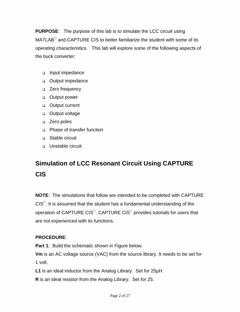
PURPOSE: The purpose of this lab is to simulate the LCC circuit using
MATLAB and CAPTURE CIS to better familiarize the student with some of its
operating characteristics. This lab will explore some of the following aspects of
the buck converter:
Input impedance
Output impedance
Zero frequency
Output power
Output current
Output voltage
Zero poles
Phase of transfer function
Stable circuit
Unstable circuit
Simulation of LCC Resonant Circuit Using CAPTURE
CIS
NOTE: The simulations that follow are intended to be completed with CAPTURE
CIS. It is assumed that the student has a fundamental understanding of the
operation of CAPTURE CIS. CAPTURE CIS provides tutorials for users that
are not experienced with its functions.
PROCEDURE:
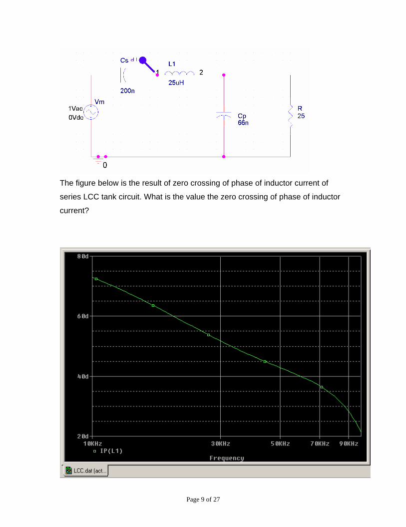
Part 1: Build the schematic shown in Figure below.
Vm is an AC voltage source (VAC) from the source library. It needs to be set for
1 volt.
L1 is an ideal inductor from the Analog Library. Set for 25µH.
R is an ideal resistor from the Analog Library. Set for 25.
Page 3 of 27
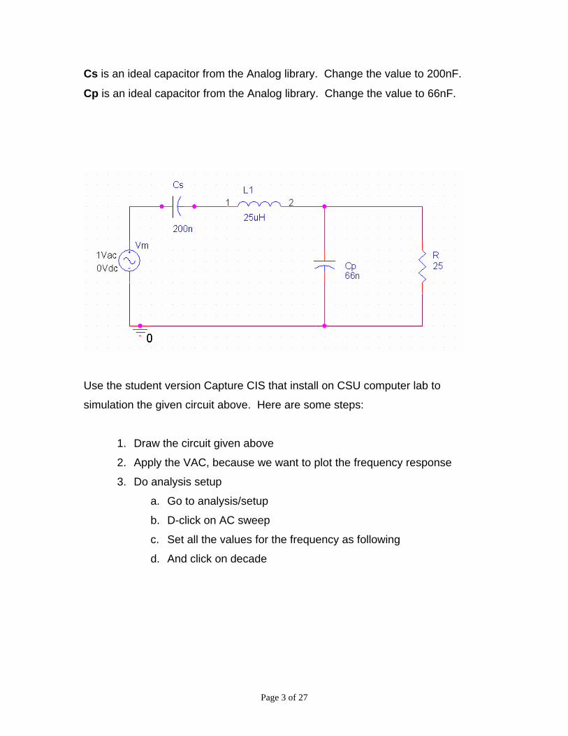
Cs is an ideal capacitor from the Analog library. Change the value to 200nF.
Cp is an ideal capacitor from the Analog library. Change the value to 66nF.
Use the student version Capture CIS that install on CSU computer lab to
simulation the given circuit above. Here are some steps:
1. Draw the circuit given above
2. Apply the VAC, because we want to plot the frequency response
3. Do analysis setup
a. Go to analysis/setup
b. D-click on AC sweep
c. Set all the values for the frequency as following
d. And click on decade

Page 4 of 27
Click OK
4. Analysis/run probe
The figure below is the result of impedance of series RLC tank circuit. What is
the input impedance value of LCC circuit?

Page 5 of 27
Next, we want to run the simulation of the output voltage of the LCC circuit. Use
the same circuit as above, and place voltage markers as shown in the
schematic below.
This figure shows the output voltage of LCC circuit. What is the output voltage of LCC circuit?

Page 6 of 27
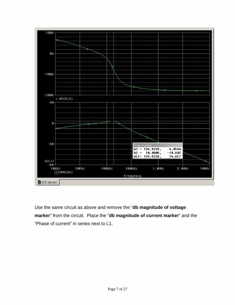
Now remove voltage markers from the circuit, and place the “db magnitude of
voltage marker” in series next to output resistor. The figure below is the result
of output voltage of series LCC tank circuit. What is the value of output voltage of
LCC circuit? What is the phase value output voltage of LCC circuit?
Page 7 of 27
Use the same circuit as above and remove the “db magnitude of voltage
marker” from the circuit. Place the “db magnitude of current marker” and the
“Phase of current” in series next to L1.

Page 8 of 27
The figure below is the result of inductor current of series LCC tank circuit. What
is the value of inductor current of LCC circuit? What is the phase value of
inductor current of LCC circuit?
Next, find the zero crossing of phase of inductor current. Use the same circuit
as above and remove the “db magnitude of current marker” from the circuit.
Keep the “Phase of current” in series next to L1.
Page 9 of 27
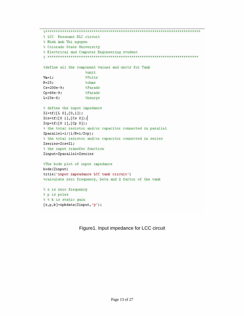
The figure below is the result of zero crossing of phase of inductor current of
series LCC tank circuit. What is the value the zero crossing of phase of inductor
current?

Page 10 of 27
Use the same circuit as above and remove the “db magnitude of current
marker” and “Phase of current” from the inductor. Place the “db magnitude of
current marker” and the “Phase of current” in series next to Cs. The figure
below is the result of capacitor current of series LCC tank circuit. What is the
value of input capacitor Cs current of LCC circuit? What is the phase value of
input capacitor (Cs) current of LCC circuit?
Use the same circuit as above and remove the “db magnitude of current
marker” and “Phase of current” from the input capacitor (Cs). Place the “db

Page 11 of 27
magnitude of current marker” in series next to output resistor. The figure
below is the result of power of series LCC tank circuit. What is the value of power
of LCC circuit?
For Homework:
You need to re-solve the LCC resonant circuit with Capacitor ESR
and see its effects on the magnitude and phase plots in some detail.
For example choose the ratio of the Cs and Cp ESR to the load
resistance to be in the ratio range from 0.01 to 1.

Page 12 of 27
Simulation of LCC Resonant Circuit Using MATLAB
NOTE: The simulations that follow are intended to be completed with MATLAB.
It is assumed that the student has a fundamental understanding of the operation
of MATLAB. MATLAB provides tutorials for users that are not experienced with
its functions.
PROCEDURE:
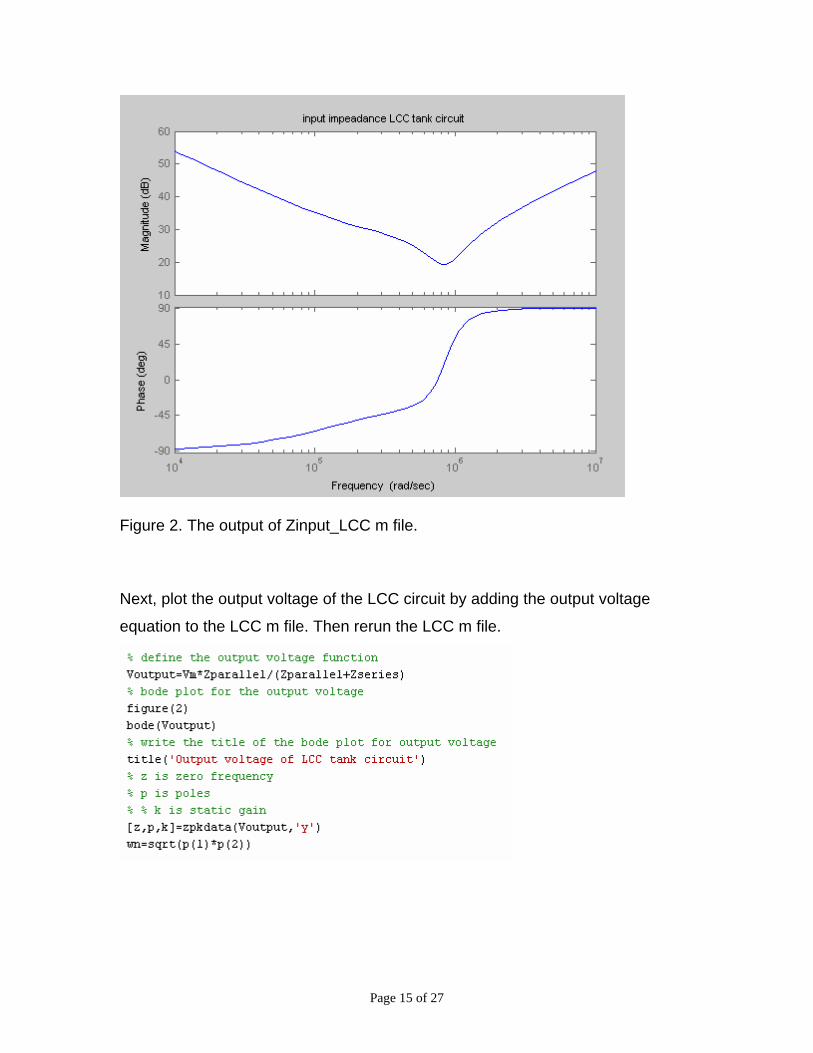
Part 1: write an m file shown in Figure 1.
Vm is a variable voltage. Set to 1 volts L is a variable inductor. Set to 25µH.
R is a variable ideal resistor. Set to 25Ω.
Cp is a variable ideal capacitor. Change the value to 66nF.
Cs is a variable ideal capacitor. Change the value to 200nF.
Page 13 of 27
Figure1. Input impedance for LCC circuit

Page 14 of 27
Once the above m file is captured, the simulations can be run. First, go to your
directory. Find your m file and then run your file. If there is a red message on
your MATLAB window, then you need to correct your error. Otherwise, you will
see the solution as show in figure 2.
Page 15 of 27
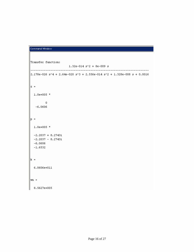
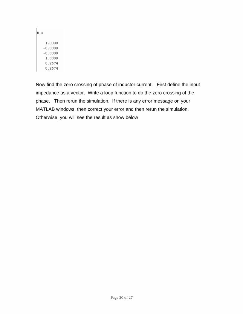
Figure 2. The output of Zinput_LCC m file. Next, plot the output voltage of the LCC circuit by adding the output voltage
equation to the LCC m file. Then rerun the LCC m file.
Page 16 of 27

Page 17 of 27
Now plot the inductor current of the LCC circuit by adding the inductor current
equations to the LCC m file. Then rerun the LCC m file.

Page 18 of 27

Page 19 of 27
Page 20 of 27
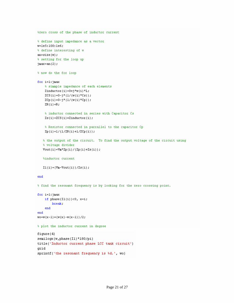
Now find the zero crossing of phase of inductor current. First define the input
impedance as a vector. Write a loop function to do the zero crossing of the
phase. Then rerun the simulation. If there is any error message on your
MATLAB windows, then correct your error and then rerun the simulation.
Otherwise, you will see the result as show below
Page 21 of 27

Page 22 of 27
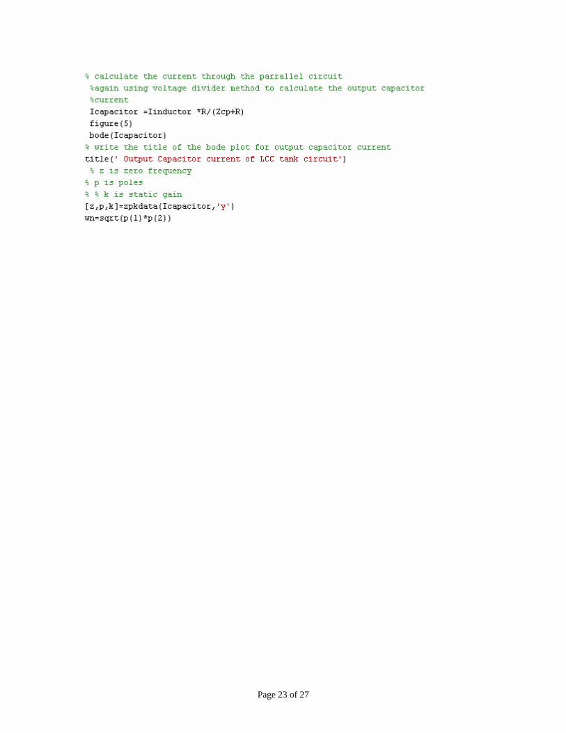
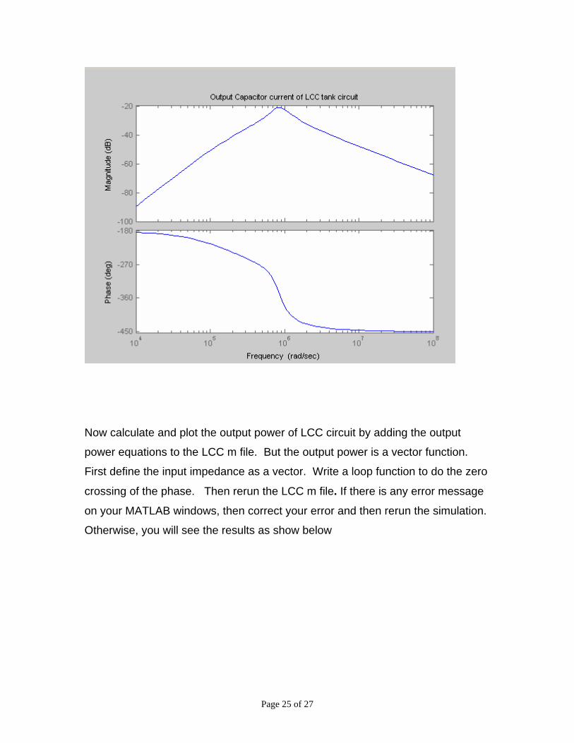
Now calculate and plot the output of capacitor current by adding the capacitor
current equations to the LCC m file. Then rerun the LCC m file. Then rerun the
simulation. If there is any error message on your MATLAB windows, then correct
your error and then rerun the simulation. Otherwise, you will see the results as
show below
Page 23 of 27

Page 24 of 27
Page 25 of 27
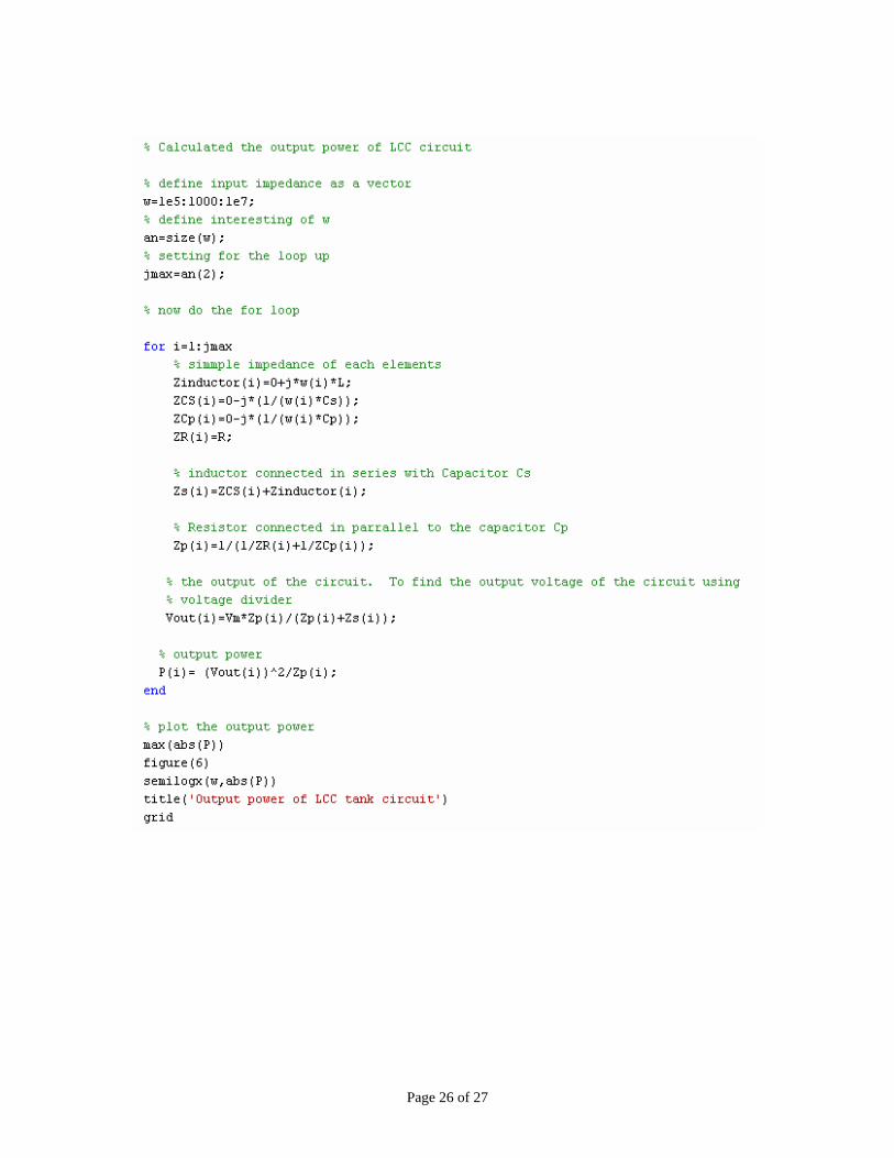
Now calculate and plot the output power of LCC circuit by adding the output
power equations to the LCC m file. But the output power is a vector function.
First define the input impedance as a vector. Write a loop function to do the zero
crossing of the phase. Then rerun the LCC m file. If there is any error message
on your MATLAB windows, then correct your error and then rerun the simulation.
Otherwise, you will see the results as show below
Page 26 of 27

Page 27 of 27
ans =
0.1769