TM P400 Metering Pump · TM P400 Metering Pump P400-991-2400C ... that exceed API 675 performance...
20
TM P400 Metering Pump P400-991-2400C Installation, Operation & Maintenance W0014B Metallic pump shown 1204 Chestnut Avenue, Minneapolis, MN 55403 Tel: (612) 332-5681 Fax: (612) 332-6937 Toll-free fax [US only]: (800) 332-6812 www.hydra-cell.com/metering email: [email protected]
Transcript of TM P400 Metering Pump · TM P400 Metering Pump P400-991-2400C ... that exceed API 675 performance...
T M
P400 Metering Pump
P400-991-2400CInstallation, Operation & Maintenance
W0014B
Metallic pump shown
1204 Chestnut Avenue, Minneapolis, MN 55403 Te l: (612) 332-5681 Fax: (612) 332- 6937 Toll-free fax [US only]: (800) 332-6812 www.hydra-cell.com/metering email: [email protected]
2 P400-991-2400C
P400 Contents PageOperation ................................................................................2Specifications ..........................................................................2Dimensions .............................................................................4Installation ...............................................................................5Calibration ...............................................................................7Maintenance ............................................................................7Fluid End Service .................................................................................8 Parts ...................................................................................12Hydraulic End Parts ..............................................................14Reducer Parts .......................................................................16Troubleshooting .....................................................................18Replacement Parts Kits ........................................................19Warranty ............................................................................... 20
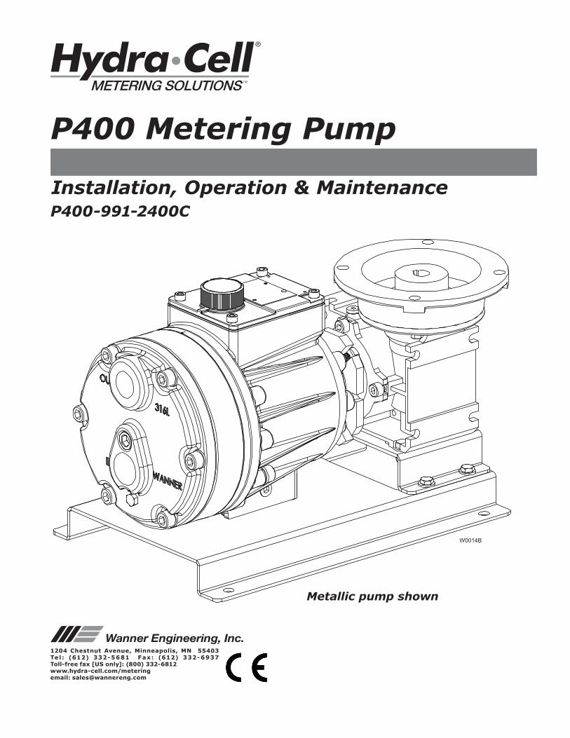
Component Identification
W0014B
Oil Fill Cap ID Plate
Outlet
Inlet
Reducer
Pump Assembly Hydraulic EndPump Assembly
Fluid End
Hydra-Cell Metering Solutions Pumps are hydraulically-actuated, hydraulically-balanced diaphragm metering pumps that exceed API 675 performance standards of ±1% steady state accuracy, ±3% linearity and ±3% repeatability. Due to their multiple diaphragm design, the P Series metering pumps, with the exception of the P100, provide virtually “pulse-free” linear flow. Unlike conventional single diaphragm metering pumps, this linear flow reduces the need for pulsation dampeners and increases the reliability, performance, and safety of the metering pump system.Pump operation and plunger activation are accomplished through a crankshaft (P100, P200 and P300) or wobble plate (P400, P500 and P600). Horizontal disk check valves allow for the pumping of particulates that ordinarily collect on vertical ball check valves common to conventional metering pumps.
P Series pumps utilize speed to adjust flow rate through a motor and variable-frequency drive (VFD), eliminating the need for mechanical adjustment.
P400 SpecificationsP400 OperationDiaphragms per Liquid End 3 (Kel-Cell pistons)Flow Control Electronic variable speed driveSteady State Accuracy ±1% Linearity ±3% Repeatability ±3%Maximum Pressure Metallic Heads: 1000 psi (69 bar) Non-Metallic Heads: PVDF: 350 psi (24 bar) Polypropylene: 250 psi (17 bar)Maximum Inlet Pressure 250 psi (17 bar)Fluid Operating Temperatures* Metallic Head: 250°F (121°C) Non-Metallic Head: 140°F (60°C) * Consult factory for correct component selection for temperatures from 160˚F (71˚C) to 250˚F (121˚C).Inlet Port 1 inch NPT or BSPTDischarge Port 3/4 inch NPT or BSPTMaximum Solids 500 micronsShaft Rotation Bi-directionalMaterials Used See Replacement Parts Kits Section for individual pump materials.Oil Capacity 1.35 US quart (1.27 liters)Weight (less motor) Metallic Heads: 65.5 lbs (29.7 kg) Non-Metallic Heads: 52.5 lbs (23.8kg)
3 P400-991-2400C
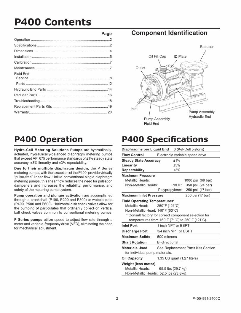
All Pumps (gph) Metallic Pump Heads Only (gph) Pump
rpmGearRatio
Motorrpm100 psi 250 psi 500 psi 1000 psi
9.637 (¼) 9.280 (¼) 8.491 (¼) 6.464 (½) 30 60:1
1800
11.652 (¼) 11.283 (¼) 10.452 (½) 8.269 (½) 36 50:1
14.66 (¼) 14.30 (¼) 13.37 (½) 11.21 (½) 45 40:1
19.73 (¼) 19.31 (¼) 18.30 (½) 15.96 (¾) 60 30:1
23.79 (¼) 23.32 (¼) 22.24 (½) 19.75 (¾) 72 25:1
29.87 (¼) 29.34 (¼) 28.15 (½) 25.45 (¾) 90 20:1
40.011 (¼) 39.375 (½) 38.00 (½) 34.94 (1) 120 15:1
60.290 (¼) 59.438 (½) 57.70 (¾) 53.92 (1) 180 10:1
80.569 (¼) 79.501 (½) 77.41 (¾) 72.90 (1½) 240 7.5:1
121.1 (½) 119.6 (¾) 116.8 (1) 110.9 (2) 360 5:1
161.69 (½) 159.75 (1) 156.22 (1½) 148.84 (3) 480 7.5:13600
242.80 (¾) 240.01 (1½) 235.03 (2.1) 224.77 (5) 720 5:1
P400 Specifications (Cont’d)Performance Maximum Flow at Designated Pressure - Imperial *
*Capacity data shown is for pumps with elastomeric diaphragms. Consult factory for performance characteristics of pumps with PTFE diaphragms. ( ) Required Motor hp
Performance Maximum Flow at Designated Pressure - Metric *
*Capacity data shown is for pumps with elastomeric diaphragms. Consult factory for performance characteristics of pumps with PTFE diaphragms. ( ) Required Motor kW
All Pumps (lph) Metallic Pump Heads Only (lph) Pumprpm
GearRatio
Motorrpm7 bar 17 bar 34 bar 69 bar
30.40 (0.18) 29.27 (0.18) 26.78 (0.25) 20.391 (0.37) 25 60:1
1500
36.76 (0.18) 35.59 (0.25) 32.97 (0.37) 26.09 (0.55) 30 50:1
46.25 (0.18) 45.10 (0.25) 42.18 (0.37) 35.36 (0.55) 37.5 40:1
62.24 (0.18) 60.92 (0.25) 57.72 (0.37) 50.33 (0.75) 50 30:1
75.04 (0.18) 73.58 (0.25) 70.15 (0.37) 62.31 (0.75) 60 25:1
94.23 (0.18) 92.56 (0.25) 88.80 (0.37) 80.27 (0.75) 75 20:1
126.21 (0.25) 124.21 (0.37) 119.87 (0.55) 110.21 (1.1) 100 15:1
190.19 (0.25) 187.50 (0.37) 182.03 (0.55) 170.09 (1.1) 150 10:1
254.16 (0.25) 250.79 (0.55) 244.18 (0.75) 229.98 (1.1) 200 7.5:1
382.1 (0.37) 377.4 (0.55) 368.5 (0.75) 349.7 (1.5) 300 5:1
510.0 (0.55) 503.9 (0.75) 492.8 (1.5) 469.5 (1.5) 400 7.5:13000
765.9 (0.55) 757.1 (0.75) 741.4 (2.2) 709.0 (2.2) 600 5:1
4 P400-991-2400C
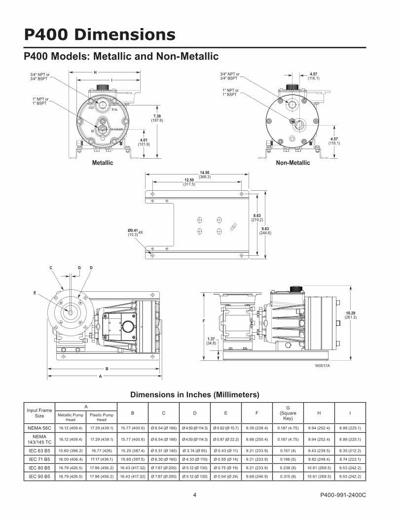
P400 Dimensions
Ø0.41(10.3) 4X
8.63(219.2)
9.63(244.6)
14.50(368.3)
12.50(317.5)
W0017A
E
C DG
B
A
10.29(261.3)
1.37(34.8)
F
4.01(101.9)
7.39(187.6)
H3/4" NPT or3/4" BSPT
1" NPT or1" BSPT
I
Metallic
3/4" NPT or3/4" BSPT
1" NPT or1" BSPT
4.57(116.1)
4.57(116.1)
Non-Metallic
P400 Models: Metallic and Non-Metallic
Input Frame Size
AB C D E F
G (Square
Key)H IMetallic Pump
HeadPlastic Pump
Head
NEMA 56C 16.12 (409.4) 17.29 (439.1) 15.77 (400.6) Ø 6.54 (Ø 166) Ø 4.50 (Ø 114.3) Ø 0.62 (Ø 15.7) 9.39 (238.4) 0.187 (4.75) 9.94 (252.4) 8.86 (225.1)
NEMA 143/145 TC 16.12 (409.4) 17.29 (439.1) 15.77 (400.6) Ø 6.54 (Ø 166) Ø 4.50 (Ø 114.3) Ø 0.87 (Ø 22.2) 9.86 (250.4) 0.187 (4.75) 9.94 (252.4) 8.86 (225.1)
IEC 63 B5 15.60 (396.2) 16.77 (426) 15.25 (387.4) Ø 5.51 (Ø 140) Ø 3.74 (Ø 95) Ø 0.43 (Ø 11) 9.21 (233.9) 0.157 (4) 9.43 (239.5) 8.35 (212.2)
IEC 71 B5 16.00 (406.4) 17.17 (436.1) 15.65 (397.5) Ø 6.30 (Ø 160) Ø 4.33 (Ø 110) Ø 0.55 (Ø 14) 9.21 (233.9) 0.196 (5) 9.82 (249.4) 8.74 (222.1)
IEC 80 B5 16.79 (426.5) 17.96 (456.2) 16.43 (417.32) Ø 7.87 (Ø 200) Ø 5.12 (Ø 130) Ø 0.75 (Ø 19) 9.21 (233.9) 0.236 (6) 10.61 (269.5) 9.53 (242.2)
IEC 90 B5 16.79 (426.5) 17.96 (456.2) 16.43 (417.32) Ø 7.87 (Ø 200) Ø 5.12 (Ø 130) Ø 0.94 (Ø 24) 9.69 (246.9) 0.315 (8) 10.61 (269.5) 9.53 (242.2)
Dimensions in Inches (Millimeters)
5 P400-991-2400C
P400 InstallationLocationLocate the pump as close to the supply source as possible.Install the pump system in a lighted clean space where it will be easy to inspect and maintain.
Motor and ControllerThe P Series pump shaft can rotate in either direction, therefore direction of motor shaft rotation is not critical. Flow rate is determined by motor speed, which is controlled using an inverter duty constant torque motor and VFD. Flow rate functions can also be easily controlled using the Hydra-Cell Control Freak and appropriate motor.
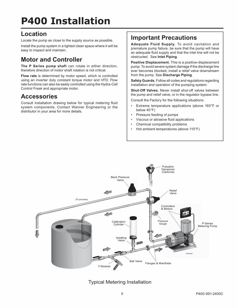
AccessoriesConsult installation drawing below for typical metering fluid system components. Contact Wanner Engineering or the distributor in your area for more details.
W0323A
(To process)
PulsationDampener(Optional)
ReliefValve
Flanges & ManifoldsBall Valve
Y-Strainer
IsolatingValve
CalibrationCylinder
PressureGauge
Back PressureValve
P-SeriesMetering Pump
Typical Metering Installation
Controllers& Motors
Important PrecautionsAdequate Fluid Supply. To avoid cavitation and premature pump failure, be sure that the pump will have an adequate fluid supply and that the inlet line will not be obstructed. See Inlet Piping.Positive Displacement. This is a positive-displacement pump. To avoid severe system damage if the discharge line ever becomes blocked, install a relief valve downstream from the pump. See Discharge Piping.Safety Guards. Follow all codes and regulations regarding installation and operation of the pumping system.Shut-Off Valves. Never install shut-off valves between the pump and relief valve, or in the regulator bypass line.Consult the Factory for the following situations:• Extreme temperature applications (above 160°F or
below 40°F)• Pressure feeding of pumps• Viscous or abrasive fluid applications• Chemical compatibility problems• Hot ambient temperatures (above 110°F)
6 P400-991-2400C
P400 Installation (Cont’d)
Inlet PipingProvide for permanent or temporary installation of a compound pressure gauge to monitor the inlet pressure. To maintain maximum flow, the pump inlet should be under flooded suction conditions at all times. Do not supply more than one pump from the same inlet line.
Supply TankUse a supply tank that is large enough to provide time for any trapped air in the fluid to escape. The tank size should be at least twice the maximum pump flow rate.Install a separate inlet line from the supply tank to each pump.Place a cover over the supply tank, to prevent foreign objects from falling into it.
Hose Sizing and RoutingTo minimize acceleration head and frictional losses, size the suction line at least one size larger than the pump inlet, and keep the suction line as short and direct as possible.
Recommendations:• Keep inlet lines less than 3 ft. (1 m) long• Use at least 5/8” (16 mm) I.D. inlet hose• Minimize fittings (elbows, valves, tees, etc.)
Support the pump and piping independently.
Inlet Piping (Pressure Feed)Provide for permanent or temporary installation of a pressure gauge to monitor the inlet pressure. Pressure at the pump inlet should not exceed 250 psi (17.3 bar). For higher pressures install a pressure reducing valve. Do not supply more than one pump from the same inlet line.Note: System back pressure must exceed the pump inlet pressure by at least 15 psi (1 bar) in order to prevent flow thru.
Discharge PipingHose and RoutingUse the shortest, most-direct route for the discharge line.Select pipe or hose with a working pressure rating of at least 1.5 times the maximum system pressure. Example: Select a 1500 psi (103 bar) W.P. rated hose for a system to be operated at 1000 psi (69 bar) gauge pressure.Support the pump and piping independently.
Pressure RegulationInstall a pressure relief valve in the discharge line. Bypass pressure must not exceed the pressure limit of the pump.Size the valve so that, when fully open, it will be large enough to relieve the full capacity of the pump without overpressurizing the system.Locate the valve as close to the pump as possible and ahead of any other valves.Adjust the pressure relief valve to no more than 10% over the maximum working pressure of the system. Do not exceed the manufacturer’s pressure rating for the pump or valve.Route the bypass line to the supply tank.Caution: Never install shutoff valves in the bypass line or between the pump and pressure regulator or relief valve.Provide for permanent or temporary installation of a pressure gauge to monitor the discharge pressure at the pump.
Minimum Discharge PressureTo ensure proper capacity control, a minimum discharge pressure of 50 psi (3.5 bar) is recommended.
Safety PrecautionsGeneral remarksThese safety / installation instructions contain fundamental information and precautionary notes and must be kept available to all associated with the operation of the pump. Please read them thoroughly prior to installation, electrical connection and commissioning of the unit. It is imperative that all other operating instructions relating to the components of individual units are followed.These safety / installation instructions do not take local regulations into account. The operator must ensure that such regulations are observed by all, including the personnel carrying out the installation. Each pump must be labeled by the end user to warn of any hazards that the system process may produce; e.g. corrosive chemicals or hot process etc.All personnel involved in the operation, maintenance, inspection and installation of the pump must be fully qualified to carry out the work. The personnel’s responsibilities, competence and supervision must be clearly defined by the operator. To the extent that if the personnel in question is not already in possession of the requisite know how, appropriate training and instruction must be provided. In addition, the operator is responsible for ensuring that the contents of the operating instructions are fully understood by all the responsible personnel.When installing a Hydra-Cell pump in conjunction with a motor or motor and frequency controller the relevant manuals must be referred to for electromagnetic compatibility. The installation should conform to EN 61800 and EN 60204 as applicable.All safety instructions in this manual and all relevant local health and safety regulations must be followed.Attention must be paid to the weight of the pump before attempting to lift either manually or selecting appropriate lifting equipment.
7 P400-991-2400C
P400 Installation (Cont’d)Initial Start-Up ProcedureBefore starting the pump, be sure that:1. All shut-off valves are open, and pump has adequate supply
of fluid.2. All connections are tight.3. The oil level is 1/4 inch (6 mm) above the cast surface in the
upper oil reservoir. 4. Open priming valve on system back pressure valve so pump
starts under minimum pressure. See Typical Metering Installation drawing.
Turn on power to pump motor and:1. Check inlet pressure or vacuum. To maintain maximum flow,
pump inlet should be under flooded suction conditions at all times. Inlet pressure must not exceed 250 psi (17.3 bar).
2. Observe any erratic noise or flow.3. Jog pump on and off until fluid coming from priming valve
is air-free.4. Close priming valve.5. Perform pump calibration. See Calibration Procedure.
P400 Maintenance
CalibrationNote: Each metering pump or pump system must be calibrated to determine the pump speed required for the desired flow rate. Accurate calibration depends on pump discharge pressure and system conditions. When calibrating the pump or system, it is useful to plot capacity curves for future reference. Observe on the curve, that pump capacity decreases slightly as discharge pressure increases. In order to achieve the best possible results, perform calibration under actual process conditions. Follow these steps:1. Run pump for 20 minutes at actual process conditions. If
process system cannot be used, circulate back to supply tank through pressure relief valve (see Typical Metering Installation drawing). If required system pressure is less than 50 psi (3.5 bar) back pressure valve must be installed and set to produce minimum of 50 psi (3.5 bar) pressure at pump head.
2. Determine maximum pump speed required for all system conditions that need to be satisfied. Measure pump delivery at this maximum speed using system calibration cylinder, flow meter, or similar container. This is the “rated capacity” for pump.
3. Measure pump delivery at 100%, 75%, 50%, 25%, and 10% of maximum speed just determined. Let pump run for 5 minutes at each speed setting before taking capacity measurement.
Note: The numbers in parentheses are Reference Numbers located in the Parts List exploded views of this manual.
PeriodicallyCAUTION: Do not turn the drive shaft while the oil reservoir is empty.CAUTION: Do not leave contaminated oil in the pump housing or leave the housing empty. Remove contaminated oil as soon as discovered and replace with clean oil.1. Check inlet pressure periodically with gauge.2. Change oil according to hours guidelines in table. 3. Change oil as follows: a. Remove brass cap (34), and allow oil and contaminants to drain completely. Catch oil and dispose of properly. b. Use suitable Hydra-Oil for the application and pump components.
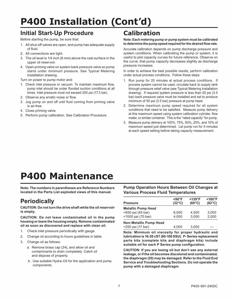
Pump Operation Hours Between Oil Changes at Various Process Fluid Temperatures <90°F <139°F <180°F Pressure (32°C) (60°C) (82°C)Metallic Pump Head <650 psi (45 bar) 6,000 4,500 3,000 <1000 psi (70 bar) 4,000 3,000 2,000
Non-Metallic Pump Head <250 psi (17 bar) 4,000 3,000 — Note: Minimum oil viscosity for proper hydraulic end lubrication is 16-20 cST (80-100 SSU). P- Series replacement parts kits (complete kits and diaphragm kits) include suitable oil for each P Series pump configuration.CAUTION: If you are losing oil but don’t see any external leakage, or if the oil becomes discolored and contaminated, the diaphragm (20) may be damaged. Refer to the Fluid End Service and Troubleshooting Sections. Do not operate the pump with a damaged diaphragm.
8 P400-991-2400C
P400 Fluid End ServiceNote: The reference numbers in parentheses are shown in the Fluid End Parts List.This section explains how to disassemble and inspect all easily-serviceable parts of the pump fluid end.Caution: Disassembly of the hydraulic end of the pump should be performed only by a qualified technician. For assistance, contact Wanner Engineering (612-332-5681) or the distributor in your area.
1. Remove Manifold (6), Valve Plate (16)a. Remove six bolts (4) and six washers (5) around manifold (6).
Do not remove bolt (25) or bolt (29) installed through back of cylinder housing (24).
b. Use 3/8-in. (10-mm) hex Allen wrench to remove center bolt (1) and washer (2).
CAUTION: Do not turn the pump drive shaft while the manifold and valve plate are off the pump, except when removing diaphragms or repriming the hydraulic cells.
c. Remove manifold (6), and support plate (42) [Non-metallic pump head only.] Valve plate (16) will remain on cylinder housing (24).
d. Inspect manifold (6) for warping or wear around inlet and outlet ports. If wear is excessive, replace the manifold.
To check if manifold is warped, remove O-rings (7,8,9) and place straightedge across it. If warped, replace.
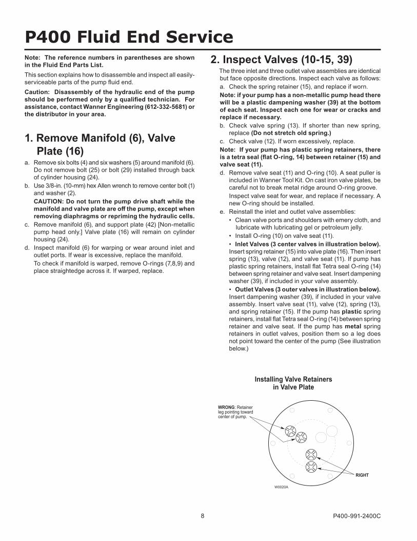
WRONG: Retainerleg pointing towardcenter of pump.
RIGHT
Installing Valve Retainersin Valve Plate
W0020A
2. Inspect Valves (10-15, 39) The three inlet and three outlet valve assemblies are identical
but face opposite directions. Inspect each valve as follows: a. Check the spring retainer (15), and replace if worn. Note: if your pump has a non-metallic pump head there
will be a plastic dampening washer (39) at the bottom of each seat. Inspect each one for wear or cracks and replace if necessary.
b. Check valve spring (13). If shorter than new spring, replace (Do not stretch old spring.)
c. Check valve (12). If worn excessively, replace. Note: If your pump has plastic spring retainers, there
is a tetra seal (flat O-ring, 14) between retainer (15) and valve seat (11).
d. Remove valve seat (11) and O-ring (10). A seat puller is included in Wanner Tool Kit. On cast iron valve plates, be careful not to break metal ridge around O-ring groove.
Inspect valve seat for wear, and replace if necessary. A new O-ring should be installed.
e. Reinstall the inlet and outlet valve assemblies: • Clean valve ports and shoulders with emery cloth, and
lubricate with lubricating gel or petroleum jelly. • Install O-ring (10) on valve seat (11). • Inlet Valves (3 center valves in illustration below).
Insert spring retainer (15) into valve plate (16). Then insert spring (13), valve (12), and valve seat (11). If pump has plastic spring retainers, install flat Tetra seal O-ring (14) between spring retainer and valve seat. Insert dampening washer (39), if included in your valve assembly.
• Outlet Valves (3 outer valves in illustration below). Insert dampening washer (39), if included in your valve assembly. Insert valve seat (11), valve (12), spring (13), and spring retainer (15). If the pump has plastic spring retainers, install flat Tetra seal O-ring (14) between spring retainer and valve seat. If the pump has metal spring retainers in outlet valves, position them so a leg does not point toward the center of the pump (See illustration below.)
9 P400-991-2400C
P400 Fluid End Service (Cont’d)4. Flush Contaminant from Hydraulic End (only if a diaphragm has ruptured) a. Remove the brass cap (34) and allow all oil and
contaminate to drain out. b. Fill reservoir with compatible solvent. Manually turn pump
shaft to circulate compatible solvent and drain. Use the shaft rotator provided in Wanner Tool Kit (Part No. A03-175-1101). Dispose of contaminated fluid properly.
CAUTION: If you have an EPDM diaphragm, or if food grade oil is in the reservoir, do not use kerosene or solvents. Instead, flush with the same lubricant that is in the reservoir.
c. Repeat step b. flushing procedure. d. Fill reservoir with fresh oil and manually turn pump shaft
to circulate oil. Drain oil. Note: P Series replacement parts kits (complete kits
and diaphragm kits) include the correct oil for each specific P Series pump configuration.
e. Refill reservoir with fresh oil. If oil appears milky, there is still contaminant in reservoir. Repeat steps c and d until oil appears clean.
3. Inspect and Replace Diaphragms (20) If necessary to service diaphragms, remove two socket-
head cap screws (41) that secure valve plate (16) to cylinder casting (24). Inspect valve plate the same as manifold in Paragraph 1, step d.
a. Lift diaphragm (20) by one edge, and turn pump shaft (use the shaft rotator from the Wanner Tool Kit) until diaphragm pulls up. This will expose machined cross-holes in plunger shaft behind diaphragm.
b. Insert plunger holder (from the Wanner Tool Kit) through one of machined cross holes to hold diaphragm up. Don’t remove tool until new diaphragm is installed in step f below.
c. Remove the screw (17), O-ring (18), and follower (19) in center of diaphragm (20).
d. Remove diaphragm (20), and inspect carefully. A damaged diaphragm generally indicates a pumping system problem. Replacing diaphragm only, will not solve the larger problem. Inspect diaphragm for following:
• Puncture. Usually caused by sharp foreign object in fluid.
• Diaphragm pulled away from center screw or from cylinder sides. Usually caused by fluid being frozen in pump, or by over-pressurization of pump.
• Diaphragm becoming stiff and losing flexibility. Usually caused by pumping fluid that is incompatible with diaphragm material.
• Diaphragm edge chewed away. Usually caused by over-pressurizing system.
e. Inspect plunger (21) for any rough surfaces or edges. Do not remove plunger from plunger shaft. Smooth surfaces and edges as necessary with emery cloth or fine file.
CAUTION: If a diaphragm has ruptured and foreign material or water has entered the oil reservoir, do not operate the pump. Check all diaphragms, then flush the reservoir completely (as outlined below) and refill it with fresh oil. Never let the pump stand with foreign material or water in the reservoir, or with the reservoir empty.
f. Install new diaphragm (20) (or old one, if not damaged), ridge side out.
g. Clean screw (17) and remove any oil from it. Apply medium-strength thread locker to screw. Reinstall screw and follower (19), and new O-ring (18). Tighten to 18 in-lbs (2.0 N-m).
h. Repeat above inspection procedure (and replacement, as necessary) with other two diaphragms.
10 P400-991-2400C
P400 Fluid End Service (Cont’d)5. Priming Hydraulic Cells Note: Providing oil prime to fitted pumps requires
pressure be applied to the diaphragms. This can be done manually, with the system head pressure, or with pressurized air if available. Review all methods below to determine the procedure most suitable.
Method 1 (system head pressure less than 2 psi) a. Install valve plate (16) but without the outlet valves
installed (or else remove outlet valves; leave seats installed) onto cylinder housing (24). Tighten two socket-head screws (41).
b. Fill reservoir with correct Hydra-oil to fill port. Note: P Series replacement parts kits (complete kits and
diaphragm kits) include the correct oil for each specific P Series pump configuration.
c. With blunt pointer (eraser end of pencil), reach in through each outlet valve port and push diaphragm (20) backwards. Note air bubbles coming out at oil fill port. Now turn shaft about 1/2 turn.
d. Repeat depressing diaphragms (20) and rotating shaft (approximately 4 to 6 times) until no more air bubbles escape and oil has dropped about 1 inch (25 mm) from top of fill port. Hydraulic cells are now primed. Replace oil fill cap (27) and O-ring (26).
e. Install outlet valve assemblies in each outlet valve port. See Parts list for correct assembly order. If necessary, tip pump (head upward) to keep valve (12) centered on valve seat (11) and allow valve retainer (15) to fit into port flush.
f. Install manifold (6) and complete installation.
Alternative Method 1 (system head pressure less than 2 psi) a. With pump horizontal, and the fluid-end head removed,
fill reservoir with correct Hydra-oil to fill port. Note: P Series replacement parts kits (complete kits and
diaphragm kits) include the correct oil for each specific P Series pump configuration.
b. Have catch basin for oil that leaks from behind diaphragms when priming. Catch oil and dispose of properly. Do not reuse oil.
c. All air in oil within hydraulic piston behind diaphragms (20) must be forced out by turning shaft (and pumping piston). A shaft rotator is included in the Hydra-Cell Tool Kit. Keep pressure on diaphragms while turning shaft until bubble-free flow of oil comes from behind all diaphragms. Maintain oil level in reservoir. Do not allow oil level to be lower than reservoir.
d. Before oil runs out past diaphragms (20), quickly attach loaded valve plate (16) with socket head screws (41). Do not tighten screws completely. Leave gap between valve plate and the cylinder housing (24). Turn shaft 2-3 turns to finish forcing out air behind diaphragms. Hydraulic cells are now primed. Finish tightening valve plate with two socket head screws (41) and add pump manifold (6).
e. Wipe excess oil from around pump head. f. Check that oil level is 1 inch (25 mm) from top of fill port. g. Replace oil fill cap (27) and O-ring (26) and complete
installation.
Method 2 (head pressure greater than 2 psi) This simple and clean method of priming Hydra-cells requires
an inlet head pressure of at least 5 feet (1.5 m) or 2 psi (.14 bar). The pressure source is required to hold the diaphragms back while the piston moves so as to force out the air.
a. Completely assemble pump and fill reservoir with correct Hydra-oil to fill port.
Note: P Series replacement parts kits (complete kits and diaphragm kits) include the correct oil for each specific P Series pump configuration.
b. When tank head pressure is being used to prime, install pump back into system and connect tank supply line to pump inlet. Pump discharge line may be connected at this time, but end of line must be open to allow air to pass out.
c. Slowly turn pump shaft by hand and watch for bubbles exiting oil reservoir fill opening. This will take several rotations; when no more bubbles come out and reservoir level has dropped about 1” (25 mm), hydraulic cells are primed.
d. Replace oil fill cap (27) and O-ring (26) and complete installation.
e. When compressed air is being used to prime, insert clean air hose to pump inlet and restrict pump outlet. Turn shaft quarter turn and then apply air pressure into manifold to put pressure on diaphragms (20). This will force air out from inside pistons. Observe for bubbles at reservoir opening. Repeat for several rotations until no more air bubbles come out and reservoir level has dropped about 1” (25 mm). Hydraulic cells are now primed.
f. Replace oil fill cap (27) and O-ring (26) and complete installation.
6. Reinstall Valve Plate (16), Manifold (6), Note: Use the cap screw (29) protruding through the
cylinder casting at the 10 o’clock position to locate the valve plate on the cylinder casting. Place the “blind hole” on the valve plate over this bolt.
a. With valve assemblies installed as outlined above, reinstall valve plate (16) onto cylinder housing (24). Recheck that blind hole is over protruding bolt at 10 o’clock position. Install two socket-head cap screws (41) and secure valve plate to cylinder casting.
b. Reinstall O-rings (7,8,9) on rear side of the manifold (6). Use a compatible petroleum jelly or lubricating gel to hold them in place.
c. Reinstall manifold (6) onto valve plate (16). Be sure drain plug (3) is installed in manifold.
Note: on pumps with non-metallic head, position support plate (42) onto manifold with ports and bolt holes aligned correctly.
d. Insert bolts (4) and washers (5). Hand tighten. e. Reinstall center bolt (1) with washer (2), and torque to 45
ft-lbs (60 N-m). f. Alternately tighten six perimeter bolts (4). Torque to 45
ft-lbs (60 N-m). g. Recheck all bolts for tightness.
11 P400-991-2400C
P400 Fluid End Parts
W0019A
22
24
3433
35
29
5 30
46
27
26
4544
25
5
37
32
17
18
19
2120
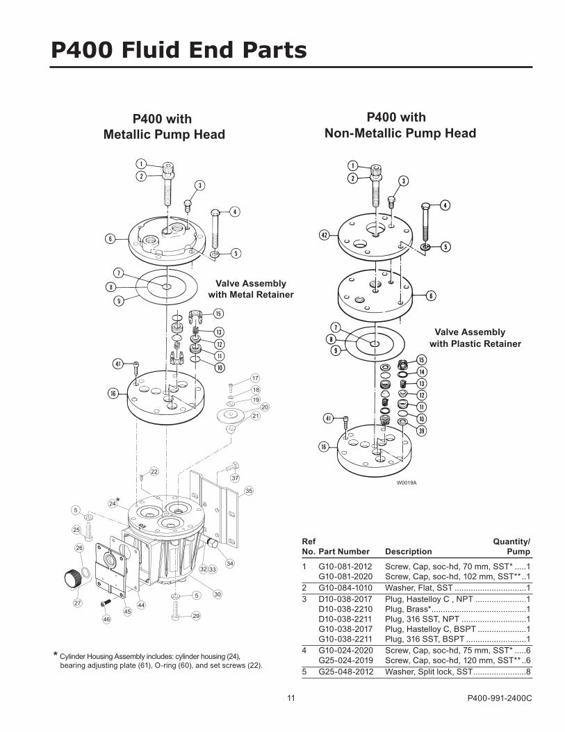
Valve Assemblywith Metal Retainer
Non-Metallic Pump Head
with Plastic Retainer
P400 with Metallic Pump Head
* Cylinder Housing Assembly includes: cylinder housing (24), bearing adjusting plate (61), O-ring (60), and set screws (22).
Valve Assembly
P400 with
*
1 G10-081-2012 Screw, Cap, soc-hd, 70 mm, SST* .....1 G10-081-2020 Screw, Cap, soc-hd, 102 mm, SST** ..12 G10-084-1010 Washer, Flat, SST ...............................13 D10-038-2017 Plug, Hastelloy C , NPT ......................1 D10-038-2210 Plug, Brass* .........................................1 D10-038-2211 Plug, 316 SST, NPT ............................1 G10-038-2017 Plug, Hastelloy C, BSPT .....................1 G10-038-2211 Plug, 316 SST, BSPT ..........................14 G10-024-2020 Screw, Cap, soc-hd, 75 mm, SST* .....6 G25-024-2019 Screw, Cap, soc-hd, 120 mm, SST** ..65 G25-048-2012 Washer, Split lock, SST .......................8
Ref Quantity/ No. Part Number Description Pump
12 P400-991-2400C
P400 Fluid End Parts List
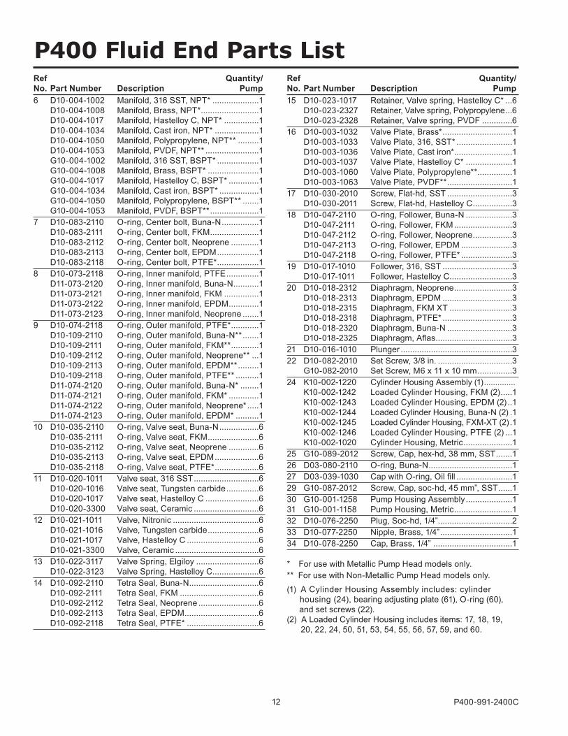
6 D10-004-1002 Manifold, 316 SST, NPT* ....................1 D10-004-1008 Manifold, Brass, NPT* .........................1 D10-004-1017 Manifold, Hastelloy C, NPT* ...............1 D10-004-1034 Manifold, Cast iron, NPT* ...................1 D10-004-1050 Manifold, Polypropylene, NPT** .........1 D10-004-1053 Manifold, PVDF, NPT** .......................1 G10-004-1002 Manifold, 316 SST, BSPT* ..................1 G10-004-1008 Manifold, Brass, BSPT* ......................1 G10-004-1017 Manifold, Hastelloy C, BSPT* .............1 G10-004-1034 Manifold, Cast iron, BSPT* .................1 G10-004-1050 Manifold, Polypropylene, BSPT** .......1 G10-004-1053 Manifold, PVDF, BSPT** .....................17 D10-083-2110 O-ring, Center bolt, Buna-N ................1 D10-083-2111 O-ring, Center bolt, FKM .....................1 D10-083-2112 O-ring, Center bolt, Neoprene ............1 D10-083-2113 O-ring, Center bolt, EPDM ..................1 D10-083-2118 O-ring, Center bolt, PTFE* ..................18 D10-073-2118 O-ring, Inner manifold, PTFE ..............1 D11-073-2120 O-ring, Inner manifold, Buna-N ...........1 D11-073-2121 O-ring, Inner manifold, FKM ...............1 D11-073-2122 O-ring, Inner manifold, EPDM .............1 D11-073-2123 O-ring, Inner manifold, Neoprene .......19 D10-074-2118 O-ring, Outer manifold, PTFE* ............1 D10-109-2110 O-ring, Outer manifold, Buna-N** .......1 D10-109-2111 O-ring, Outer manifold, FKM** ............1 D10-109-2112 O-ring, Outer manifold, Neoprene** ...1 D10-109-2113 O-ring, Outer manifold, EPDM** .........1 D10-109-2118 O-ring, Outer manifold, PTFE** ..........1 D11-074-2120 O-ring, Outer manifold, Buna-N* ........1 D11-074-2121 O-ring, Outer manifold, FKM* .............1 D11-074-2122 O-ring, Outer manifold, Neoprene* .....1 D11-074-2123 O-ring, Outer manifold, EPDM* ..........110 D10-035-2110 O-ring, Valve seat, Buna-N .................6 D10-035-2111 O-ring, Valve seat, FKM ......................6 D10-035-2112 O-ring, Valve seat, Neoprene .............6 D10-035-2113 O-ring, Valve seat, EPDM ...................6 D10-035-2118 O-ring, Valve seat, PTFE* ...................611 D10-020-1011 Valve seat, 316 SST ............................6 D10-020-1016 Valve seat, Tungsten carbide ..............6 D10-020-1017 Valve seat, Hastelloy C .......................6 D10-020-3300 Valve seat, Ceramic ............................612 D10-021-1011 Valve, Nitronic .....................................6 D10-021-1016 Valve, Tungsten carbide ......................6 D10-021-1017 Valve, Hastelloy C ...............................6 D10-021-3300 Valve, Ceramic ....................................613 D10-022-3117 Valve Spring, Elgiloy ...........................6 D10-022-3123 Valve Spring, Hastelloy C ....................614 D10-092-2110 Tetra Seal, Buna-N ..............................6 D10-092-2111 Tetra Seal, FKM ..................................6 D10-092-2112 Tetra Seal, Neoprene ..........................6 D10-092-2113 Tetra Seal, EPDM ................................6 D10-092-2118 Tetra Seal, PTFE* ...............................6
15 D10-023-1017 Retainer, Valve spring, Hastelloy C* ...6 D10-023-2327 Retainer, Valve spring, Polypropylene ...6 D10-023-2328 Retainer, Valve spring, PVDF .............616 D10-003-1032 Valve Plate, Brass* ..............................1 D10-003-1033 Valve Plate, 316, SST* ........................1 D10-003-1036 Valve Plate, Cast iron* .........................1 D10-003-1037 Valve Plate, Hastelloy C* ....................1 D10-003-1060 Valve Plate, Polypropylene** ...............1 D10-003-1063 Valve Plate, PVDF** ............................117 D10-030-2010 Screw, Flat-hd, SST ............................3 D10-030-2011 Screw, Flat-hd, Hastelloy C .................318 D10-047-2110 O-ring, Follower, Buna-N ....................3 D10-047-2111 O-ring, Follower, FKM .........................3 D10-047-2112 O-ring, Follower, Neoprene .................3 D10-047-2113 O-ring, Follower, EPDM ......................3 D10-047-2118 O-ring, Follower, PTFE* ......................319 D10-017-1010 Follower, 316, SST ..............................3 D10-017-1011 Follower, Hastelloy C ...........................320 D10-018-2312 Diaphragm, Neoprene .........................3 D10-018-2313 Diaphragm, EPDM ..............................3 D10-018-2315 Diaphragm, FKM XT ...........................3 D10-018-2318 Diaphragm, PTFE* ..............................3 D10-018-2320 Diaphragm, Buna-N ............................3 D10-018-2325 Diaphragm, Aflas .................................321 D10-016-1010 Plunger ................................................322 D10-082-2010 Set Screw, 3/8 in. ................................3 G10-082-2010 Set Screw, M6 x 11 x 10 mm ...............324 K10-002-1220 Cylinder Housing Assembly (1) .............. K10-002-1242 Loaded Cylinder Housing, FKM (2) .....1 K10-002-1243 Loaded Cylinder Housing, EPDM (2) ..1 K10-002-1244 Loaded Cylinder Housing, Buna-N (2) .1 K10-002-1245 Loaded Cylinder Housing, FXM-XT (2) .1 K10-002-1246 Loaded Cylinder Housing, PTFE (2) ...1 K10-002-1020 Cylinder Housing, Metric .....................125 G10-089-2012 Screw, Cap, hex-hd, 38 mm, SST .......126 D03-080-2110 O-ring, Buna-N ....................................127 D03-039-1030 Cap with O-ring, Oil fill ........................129 G10-087-2012 Screw, Cap, soc-hd, 45 mm”, SST ......130 G10-001-1258 Pump Housing Assembly ....................1 31 G10-001-1158 Pump Housing, Metric .........................132 D10-076-2250 Plug, Soc-hd, 1/4”................................233 D10-077-2250 Nipple, Brass, 1/4” ...............................134 D10-078-2250 Cap, Brass, 1/4” ..................................1
* For use with Metallic Pump Head models only.** For use with Non-Metallic Pump Head models only.(1) A Cylinder Housing Assembly includes: cylinder housing (24), bearing adjusting plate (61), O-ring (60), and set screws (22). (2) A Loaded Cylinder Housing includes items: 17, 18, 19, 20, 22, 24, 50, 51, 53, 54, 55, 56, 57, 59, and 60.
Ref Quantity/ No. Part Number Description Pump
Ref Quantity/ No. Part Number Description Pump
13 P400-991-2400C
P400 Fluid End Parts List (Cont’d)
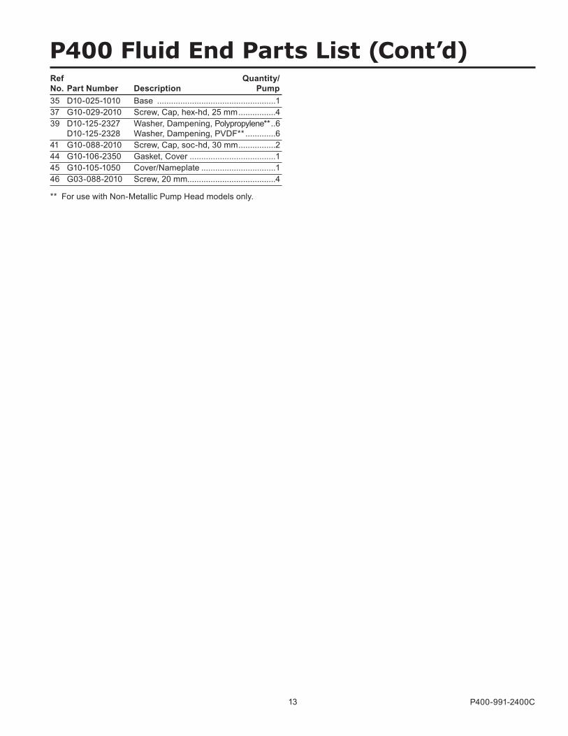
35 D10-025-1010 Base ...................................................137 G10-029-2010 Screw, Cap, hex-hd, 25 mm ................439 D10-125-2327 Washer, Dampening, Polypropylene** ..6 D10-125-2328 Washer, Dampening, PVDF** .............641 G10-088-2010 Screw, Cap, soc-hd, 30 mm ................244 G10-106-2350 Gasket, Cover .....................................145 G10-105-1050 Cover/Nameplate ................................146 G03-088-2010 Screw, 20 mm......................................4
Ref Quantity/ No. Part Number Description Pump
** For use with Non-Metallic Pump Head models only.
14 P400-991-2400C
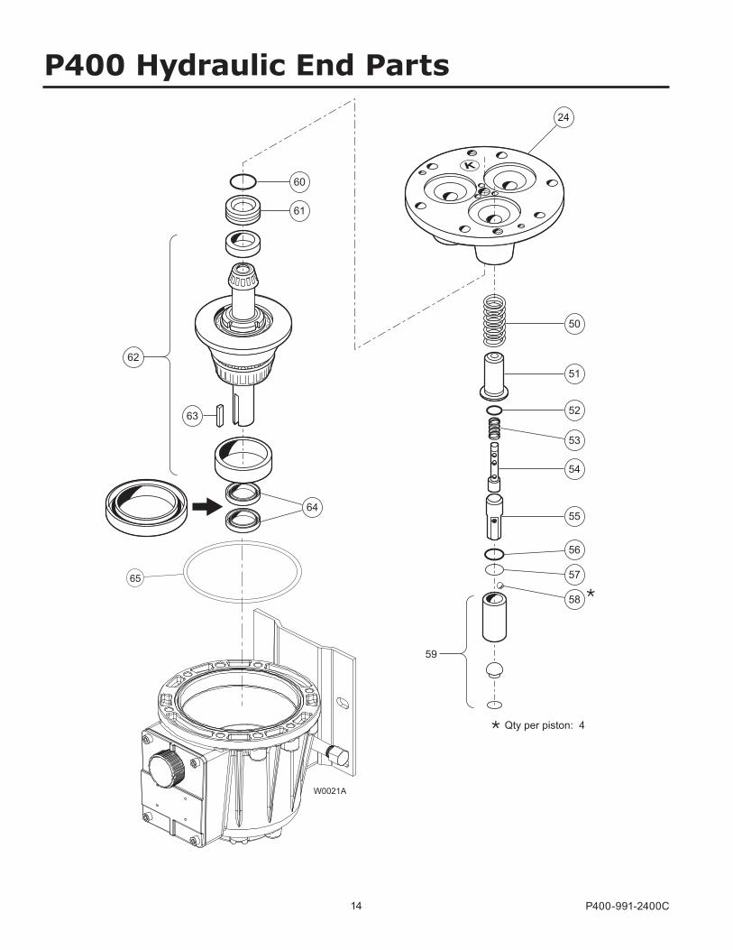
65
W0021A
24
62
61
64
60
50
51
52
53
54
55
56
57
58
63
Qty per piston: 4
59
P400 Hydraulic End Parts
15 P400-991-2400C
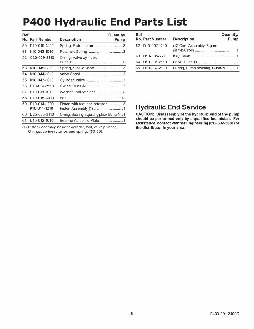
50 D10-019-3110 Spring, Piston return ...........................351 K10-042-1010 Retainer, Spring .................................352 C23-009-2110 O-ring, Valve cylinder, Buna-N ...............................................353 K10-045-3110 Spring, Sleeve valve ..........................354 K10-044-1010 Valve Spool .......................................355 K10-043-1010 Cylinder, Valve ..................................356 D10-034-2110 O-ring, Buna-N ....................................357 D10-041-1010 Washer, Ball retainer ...........................358 D10-015-3010 Ball ...................................................1259 D10-014-1209 Piston with foot and retainer ...............3 K10-014-1210 Piston Assembly (1) ............................160 D25-035-2110 O-ring, Bearing adjusting plate, Buna-N ..161 D10-012-1010 Bearing Adjusting Plate .......................1
62 D10-007-1210 (X) Cam Assembly, 8 gpm @ 1450 rpm ........................................163 D10-085-2210 Key, Shaft ............................................164 D10-031-2110 Seal , Buna-N ......................................265 D10-037-2110 O-ring, Pump housing, Buna-N...........1
Ref Quantity/ No. Part Number Description Pump
Ref Quantity/ No. Part Number Description Pump
P400 Hydraulic End Parts List
Hydraulic End ServiceCAUTION: Disassembly of the hydraulic end of the pump should be performed only by a qualified technician. For assistance, contact Wanner Engineering (612-332-5681) or the distributor in your area.(1) Piston Assembly includes cylinder, foot, valve plunger,
O-rings, spring retainer, and springs (50-59).
16 P400-991-2400C
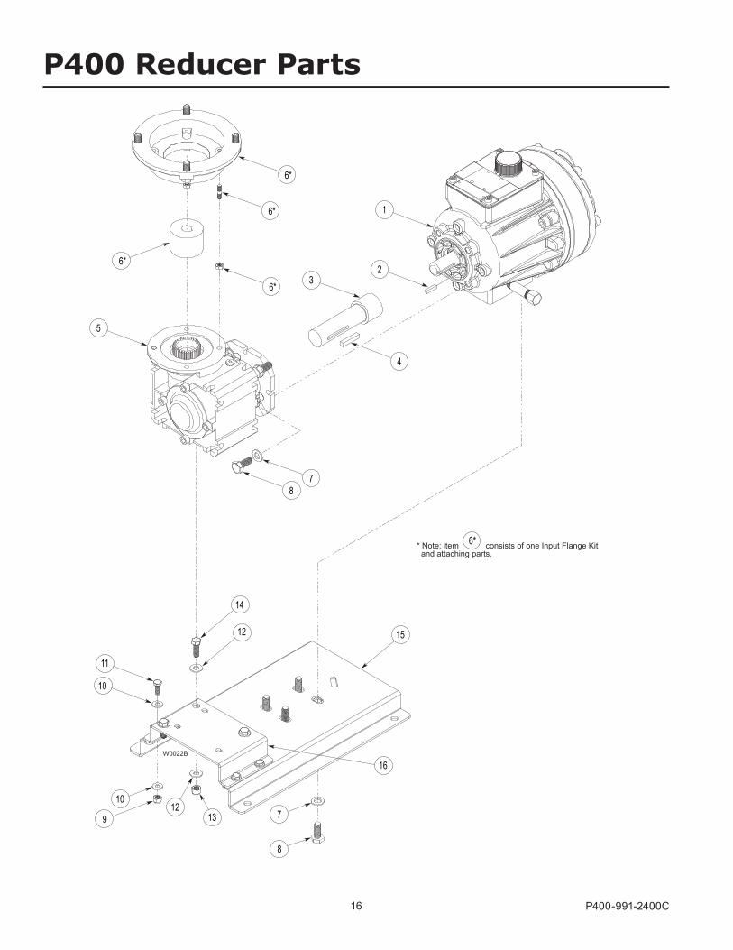
* Note: item consists of one Input Flange Kit and attaching parts.
6*
6*
W0022B
6*
6*
6*
1
5
4
32
7 8
12
11
10
16
15
14
10
9 12
13 7
8
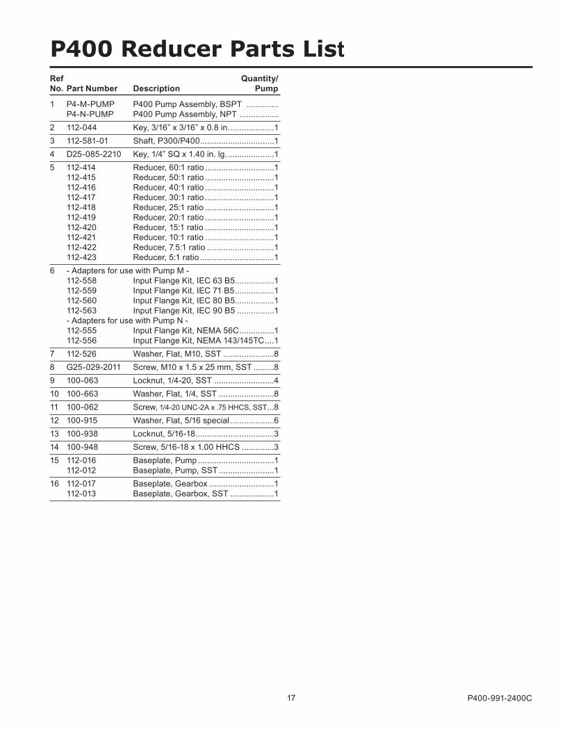
P400 Reducer Parts
17 P400-991-2400C
1 P4-M-PUMP P400 Pump Assembly, BSPT .............. P4-N-PUMP P400 Pump Assembly, NPT ................. 2 112-044 Key, 3/16” x 3/16” x 0.8 in. ...................13 112-581-01 Shaft, P300/P400 ................................14 D25-085-2210 Key, 1/4” SQ x 1.40 in. lg. ....................15 112-414 Reducer, 60:1 ratio ..............................1 112-415 Reducer, 50:1 ratio ..............................1 112-416 Reducer, 40:1 ratio ..............................1 112-417 Reducer, 30:1 ratio ..............................1 112-418 Reducer, 25:1 ratio ..............................1 112-419 Reducer, 20:1 ratio ..............................1 112-420 Reducer, 15:1 ratio ..............................1 112-421 Reducer, 10:1 ratio ..............................1 112-422 Reducer, 7.5:1 ratio .............................1 112-423 Reducer, 5:1 ratio ................................16 - Adapters for use with Pump M - 112-558 Input Flange Kit, IEC 63 B5.................1 112-559 Input Flange Kit, IEC 71 B5 .................1 112-560 Input Flange Kit, IEC 80 B5.................1 112-563 Input Flange Kit, IEC 90 B5 ................1 - Adapters for use with Pump N - 112-555 Input Flange Kit, NEMA 56C ...............1 112-556 Input Flange Kit, NEMA 143/145TC ....17 112-526 Washer, Flat, M10, SST ......................88 G25-029-2011 Screw, M10 x 1.5 x 25 mm, SST .........89 100-063 Locknut, 1/4-20, SST ..........................410 100-663 Washer, Flat, 1/4, SST ........................811 100-062 Screw, 1/4-20 UNC-2A x .75 HHCS, SST ...812 100-915 Washer, Flat, 5/16 special ...................613 100-938 Locknut, 5/16-18 ..................................314 100-948 Screw, 5/16-18 x 1.00 HHCS ..............315 112-016 Baseplate, Pump .................................1 112-012 Baseplate, Pump, SST ........................116 112-017 Baseplate, Gearbox ............................1 112-013 Baseplate, Gearbox, SST ...................1
P400 Reducer Parts ListRef Quantity/ No. Part Number Description Pump

18 P400-991-2400C
P400 TroubleshootingProblem Probable Cause Solution
Motor/Pump Does Not Operate:
No power. Supply correct power according to motor requirements.
Blown fuse/tripped circuit breaker.
Replace/reset, eliminate circuit overload.
Shaft coupling to pump not in place.
Install proper coupling hardware (see parts list).
Current overload - motor. Motor not rated for pump operating conditions - install proper motor.
Thermal overload - motor. Motor not rated for pump and/or ambient operating conditions - supply cooling or install proper motor.
Faulty motor drive/controller. Repair/replace.Faulty motor. Repair/replace.Low liquid level in supply tank (if low-level shut-off is used).
Fill tank.
No Delivery
Supply tank empty. Fill tank.Loss of prime Re-prime using Initial Start-Up Procedure.Inlet line or strainer clogged. Clear debris and flush, or replace.Inadequate supply pressure at pump inlet.
Increase supply pressure by raising fluid level in tank, raising tank, or pressurizing suction tank.
Inlet line too restrictive. Increase inlet line diameter and/or decrease inlet line length.Fluid viscosity too high. Reduce viscosity if possible (by heat or some other means). Increase inlet
line diameter and/or decrease inlet line length. Increase supply pressure.Vapor lock/cavitation. Increase inlet pressure. Decrease fluid temperature.Pump valves held open or worn out.
Clear debris and flush, or replace (see Fluid End Service)
System relief valve actuating. Adjust relief valve, or repair, clean, or replace with new relief valve.
Delivery Too Low and/or
Erratic
Review all Probable Causes and Solutions in Problem 2 No Delivery above.Air leak(s) in inlet line. Locate all leaks and repair.System back pressure too low. Adjust back pressure valve to higher setting. Install back pressure valve if
none in system.
Pumped fluid characteristics changed.
Monitor supply tank temperature to determine if fluid is too hot (leading to cavitation) or too cold (increasing fluid viscosity). Stabilize temperature at suitable level to resolve problem. Check for entrapped air in the fluid supply system.
Inlet supply pressure changed. Monitor inlet supply pressure (at the pump) to determine if it is too low, causing a starved condition/cavitation. Stabilize pressure at suitable level to resolve problem.
Pump OK - Calibration system or flow meter error.
Evaluate components and repair/correct problem(s).
Oil condition in pump hydraulic end changed.
Check oil level - if low evaluate for source of leakage. Consult factory for hydraulic end service.Change oil per recommended guidelines in maintenance section.
Delivery Too High and/or
Erratic.
System back pressure too low. Adjust back pressure valve to higher setting. Install back pressure valve if none in system.
Inlet supply pressure changed. Monitor inlet supply pressure (at the pump) to determine if it is too high, causing a “flow-through” condition. Stabilize pressure at suitable level to resolve problem.
Pump OK - Calibration system or flow meter error.
Evaluate components and repair/correct problem(s).
19 P400-991-2400C
P400 Replacement Parts Kits
6 95321 84 7
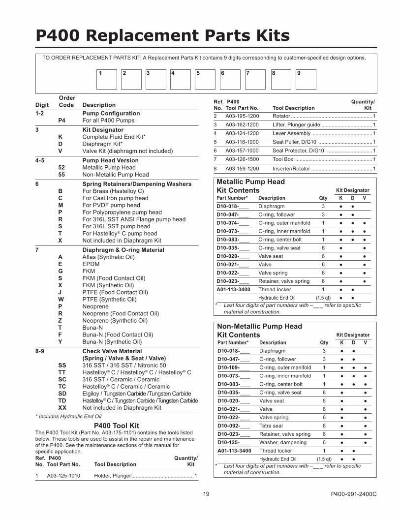
TO ORDER REPLACEMENT PARTS KIT: A Replacement Parts Kit contains 9 digits corresponding to customer-specified design options.
Kit DesignatorPart Number* Description Qty K D VD10-018-___ Diaphragm 3 • •D10-047-___ O-ring, follower 3 • • D10-074-___ O-ring, outer manifold 1 • • •D10-073-___ O-ring, inner manifold 1 • • •D10-083-___ O-ring, center bolt 1 • • •D10-035-___ O-ring, valve seat 6 • •D10-020-___ Valve seat 6 • •D10-021-___ Valve 6 • •D10-022-___ Valve spring 6 • •D10-023-___ Retainer, valve spring 6 • •A01-113-3400 Thread locker 1 • • Hydraulic End Oil (1.5 qt) • •
Metallic Pump Head Kit Contents
* Last four digits of part numbers with –___ refer to specific material of construction.
Kit DesignatorPart Number* Description Qty K D VD10-018-___ Diaphragm 3 • •D10-047-___ O-ring, follower 3 • • D10-109-___ O-ring, outer manifold 1 • • •D10-073-___ O-ring, inner manifold 1 • • •D10-083-___ O-ring, center bolt 1 • • •D10-035-___ O-ring, valve seat 6 • •D10-020-___ Valve seat 6 • •D10-021-___ Valve 6 • •D10-022-___ Valve spring 6 • •D10-092-___ Tetra seal 6 • •D10-023-___ Retainer, valve spring 6 • •D10-125-___ Washer, dampening 6 • •A01-113-3400 Thread locker 1 • • Hydraulic End Oil (1.5 qt) • •
Non-Metallic Pump Head Kit Contents
* Last four digits of part numbers with –___ refer to specific material of construction.
1-2 Pump Configuration P4 For all P400 Pumps3 Kit Designator K Complete Fluid End Kit* D Diaphragm Kit* V Valve Kit (diaphragm not included)4-5 Pump Head Version 52 Metallic Pump Head 55 Non-Metallic Pump Head6 Spring Retainers/Dampening Washers B For Brass (Hastelloy C) C For Cast Iron pump head M For PVDF pump head P For Polypropylene pump head R For 316L SST ANSI Flange pump head S For 316L SST pump head T For Hastelloy® C pump head X Not included in Diaphragm Kit7 Diaphragm & O-ring Material A Aflas (Synthetic Oil) E EPDM G FKM S FKM (Food Contact Oil) X FKM (Synthetic Oil) J PTFE (Food Contact Oil) W PTFE (Synthetic Oil) P Neoprene R Neoprene (Food Contact Oil) Z Neoprene (Synthetic Oil) T Buna-N F Buna-N (Food Contact Oil) Y Buna-N (Synthetic Oil)8-9 Check Valve Material (Spring / Valve & Seat / Valve) SS 316 SST / 316 SST / Nitronic 50 TT Hastelloy® C / Hastelloy® C / Hastelloy® C SC 316 SST / Ceramic / Ceramic TC Hastelloy® C / Ceramic / Ceramic SD Elgiloy / Tungsten Carbide /Tungsten Carbide TD Hastelloy® C / Tungsten Carbide /Tungsten Carbide XX Not included in Diaphragm Kit
Order Digit Code Description
* Includes Hydraulic End Oil
1 A03-125-1010 Holder, Plunger ...........................................1
Ref. P400 Quantity/ No. Tool Part No. Tool Description Kit
P400 Tool KitThe P400 Tool Kit (Part No. A03-175-1101) contains the tools listed below. These tools are used to assist in the repair and maintenance of the P400. See the maintenance sections of this manual for specific application.
2 A03-195-1200 Rotator ........................................................13 A03-162-1200 Lifter, Plunger guide ...................................14 A03-124-1200 Lever Assembly .........................................15 A03-118-1000 Seat Puller, D/G10 .....................................16 A03-157-1000 Seal Protector, D/G10 ...............................17 A03-126-1500 Tool Box .....................................................1
8 A03-159-1200 Inserter/Rotator ..........................................1
Ref. P400 Quantity/ No. Tool Part No. Tool Description Kit
World Headquarters & Manufacturing Wanner Engineering, Inc 1204 Chestnut Avenue, Minneapolis, MN 55403 USA Phone: 612-332-5681 ● Fax: 612-332-6937 Toll-Free Fax (USA): 800-332-6812 Email: [email protected] www.Hydra-Cell.com 207 US Highway 281 Wichita Falls, TX 76310 USA Phone: 940-322-7111 Toll-Free Fax: 800-234-1384 Email: [email protected] www.Hydra-Cell.com Latin American Office São Paulo, Brazil Phone: +55 (11) 4081-7098 Email: [email protected] www.Hydra-Cell.com
Wanner Engineering, Inc.
Wanner International Ltd Hampshire - United Kingdom Phone: +44 (0) 1252 816847 Email: [email protected] www.Hydra-Cell.eu
Wanner International Ltd.
Wanner Pumps Ltd. Kowloon - Hong Kong Phone: +852 3428 6534 Email: [email protected] www.WannerPumps.com Shanghai - China Phone: +86-21-6876 3700 Email: [email protected] www.WannerPumps.com
Wanner Pumps Ltd.
P400 Warranty
P400-991-2400C 4/2005, Revised 2/2017 © 2005 Wanner Engineering, Inc. Printed in USA
Limited WarrantyWanner Engineering, Inc. extends to the original purchaser of equipment manufactured by it and bearing its name, a limited one-year warranty from the date of purchase against defects in material or workmanship, provided that the equipment is installed and operated in accordance with the recommendations and instructions of Wanner Engineering, Inc. Wanner Engineering, Inc. will repair or replace, at its option, defective parts without charge if such parts are returned with transportation charges prepaid to Wanner Engineering, Inc., 1204 Chestnut Avenue, Minneapolis, Minnesota 55403.This warranty does not cover:1. The electric motors (if any), which are covered by the separate warranties of the manufacturers of these components.2. Normal wear and/or damage caused by or related to abrasion, corrosion, abuse, negligence, accident, faulty installation or tampering in a manner which impairs normal operation.3. Transportation costs.This limited warranty is exclusive, and is in lieu of any other warranties (express or implied) including warranty of merchantability or warranty of fitness for a particular purpose and of any non-contractual liabilities including product liabilities based on negligence or strict liability. Every form of liability for direct, special, incidental or consequential damages or loss is expressly excluded and denied.