
TM 11-5860-200-12 OPERATOR'S AND ORGANIZATIONAL ... · TM 11-5860-200-12 WARNING The light source...
82
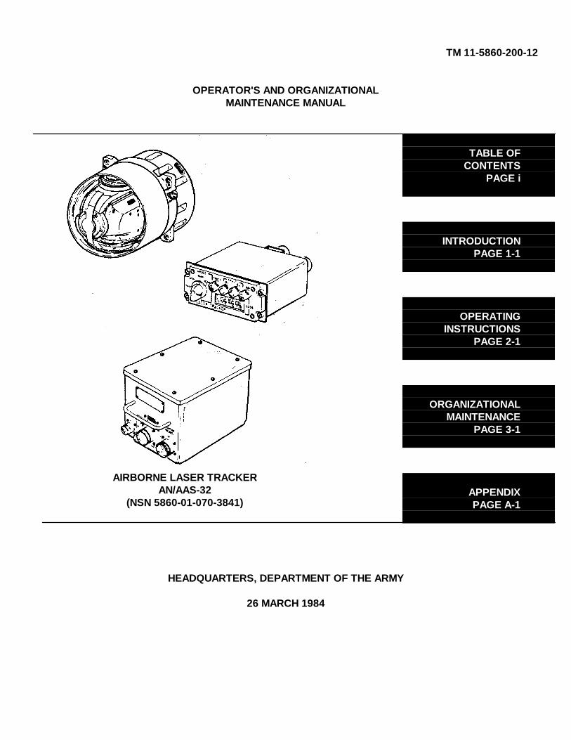
TM 11-5860-200-12 OPERATOR'S AND ORGANIZATIONAL MAINTENANCE MANUAL AIRBORNE LASER TRACKER AN/AAS-32 (NSN 5860-01-070-3841) TABLE OF CONTENTS PAGE i INTRODUCTION PAGE 1-1 OPERATING INSTRUCTIONS PAGE 2-1 ORGANIZATIONAL MAINTENANCE PAGE 3-1 APPENDIX PAGE A-1 HEADQUARTERS, DEPARTMENT OF THE ARMY 26 MARCH 1984
Transcript of TM 11-5860-200-12 OPERATOR'S AND ORGANIZATIONAL ... · TM 11-5860-200-12 WARNING The light source...
TM 11-5860-200-12
OPERATOR'S AND ORGANIZATIONALMAINTENANCE MANUAL
AIRBORNE LASER TRACKERAN/AAS-32
(NSN 5860-01-070-3841)
TABLE OFCONTENTS
PAGE i
INTRODUCTIONPAGE 1-1
OPERATINGINSTRUCTIONS
PAGE 2-1
ORGANIZATIONALMAINTENANCE
PAGE 3-1
APPENDIXPAGE A-1
HEADQUARTERS, DEPARTMENT OF THE ARMY
26 MARCH 1984

TM 11-5860-200-12
WARNING
The light source from the laser simulator is an infrared light source. The light beam is invisibleto the naked eye. The lens should not be viewed directly to prevent possible eye damage.
WARNING
Do not view laser simulator through Telescopic Sight Unit, as possible eye damage could occur.
WARNING
Do not work on or near forward pylon fairing assembly until helicopter rotor stops turning.
WARNING
Ensure aircraft battery is disconnected before installing or removing any ALT component. Deathor serious injury could result if aircraft battery remains connected.
Refer to FM 21-11 for First Aid.
a/(b blank)

TM 11-5860-200-12
Technical Manual HEADQUARTERSDEPARTMENT OF THE ARMY
No. 11-5860-200-12 Washington, DC, 26 March 1984
OPERATOR'S AND ORGANIZATIONAL MAINTENANCE MANUALAIRBORNE LASER TRACKER AN/AAS-32
(NSN 5860-01-070-3841)
REPORTING ERRORS AND RECOMMENDING IMPROVEMENTS
You can help improve this manual If you find any mistakes or if you know of a way to improve theprocedures. please let us know. Mail your letter. DA Form 2028 (Recommended Changes toPublications and Blank Forms). or DA Form 2028-2 located in back of this manual direct to:Commander. US Army Communications - Electronics Command and Fort Monmouth ATTN: DRSEL-ME-MP Fort Monmouth. New Jersey. 07703. A reply will be furnished to you.
Paragraph Page
CHAPTER 1 INTRODUCTION 1-1Section I. General Information 1-1
Scope....................................................................................................... 1-1 1-1Consolidated Index of Army Publicationsand Blank Forms ...................................................................................... 1-2 1-1Maintenance Forms, Records, andReports..................................................................................................... 1-3 1-1Destruction of Army Materiel To PreventEnemy Use............................................................................................... 1-4 1-2Preparation for Storage or Shipment......................................................... 1-5 1-2Reporting Equipment ImprovementRecommendations (EIR)........................................................................... 1-6 1-2Nomenclature Cross-Reference List ......................................................... 1-7 1-2
II. Equipment Description................................................................................... 1-3Equipment Characteristics, Features andCapabilities............................................................................................... 1-8 1-3Equipment Data........................................................................................ 1-9 1-3Locations and Description of ALT MajorComponents ........................................................................................... 1-10 1-4Location and Description of AncillaryEquipment .............................................................................................. 1-11 1-6
III. Technical Principles of Operation .................................................................. 1-8Operating Principles ............................................................................... 1-12 1-8
i

TM 11-5860-200-12
Paragraph Page
CHAPTER 2 OPERATING INSTRUCTIONS 2-1Section I. Description and Use of Operator's
Controls and Indicators .................................................................................. 2-1Controls and Indicators ............................................................................. 2-1 2-1
II. Operator Preventive Maintenance Checksand Services (PMCS) ............................................................................... 2-2 2-2Routine Checks and Services ................................................................... 2-3 2-2
III. Operation Under Usual Conditions................................................................. 2-3Preliminary Operating Procedures ............................................................ 2-4 2-3Preflight Checkout .................................................................................... 2-5 2-4
CHAPTER 3 ORGANIZATIONAL MAINTENANCE 3-1Section I. Repair Parts, Special Tools; Test,
Measurement, and Diagnostic Equipment(TMDE); and Support Equipment................................................................... 3-1Common Tools and Equipment................................................................. 3-1 3-1Special Tools, TMDE. and SupportEquipment ................................................................................................ 3-2 3-1Repair Parts ............................................................................................. 3-3 3-1
II. Service Upon Receipt.................................................................................... 3-1General .................................................................................................... 3-4 3-1Checking Unpacked Equipment ................................................................ 3-5 3-3Unpacking the Electronic Assembly.Control Panel, or Technical Manual .......................................................... 3-6 3-3Unpacking the Receiver............................................................................ 3-7 3-4
III. Organizational Preventive MaintenanceChecks and Services (PMCS)........................................................................ 3-6Organizational PMCS ............................................................................... 3-8 3-6
IV. Organizational TroubleshootingProcedures .................................................................................................... 3-7ALT Troubleshooting Procedures.............................................................. 3-9 3-7Self Test................................................................................................. 3-10 3-7ALT/Telescopic Sight Unit (TSU)Procedure............................................................................................... 3-11 3-9
ii

TM 11-5860-200-12
Paragraph Page
V. Removal and Installation Procedures............................................................. 3-18Gaining Access to Receiver andElectronics Assembly.............................................................................. 3-12 3-18Installing Forward Pylon FairingAssembly................................................................................................ 3-13 3-18Removal of Receiver from Helicopter ..................................................... 3-14 3-20Installation of Receiver into Helicopter.................................................... 3-15 3-21Removal of Electronics Assembly........................................................... 3-16 3-22Installation of Electronics Assembly........................................................ 3-17 3-24Removal of Control Panel....................................................................... 3-18 3-26Installation of Control Panel.................................................................... 3-19 3-26
VI. Repair, Checkout, Shipment .......................................................................... 3-28Repair of Control Panel .......................................................................... 3-20 3-28Cleaning ................................................................................................. 3-21 3-31Paint Touch-Up....................................................................................... 3-22 3-32Lubrication............................................................................................. .3-23 3-34Checkout ............................................................................................... .3-24 3-34Preparation for Shipment........................................................................ 3-25 3-34Packing the Receiver.............................................................................. 3-26 3-34Packing the Electronics Assembly,Control Panel, or Technical Manual ........................................................ 3-27 3-36
APPENDIX A. REFERENCES.............................................................................................. A-1B. MAINTENANCE ALLOCATION ..................................................................... B-1C. COMPONENTS OF END ITEM ..................................................................... C-1D. EXPENDABLE SUPPLIES AND
MATERIALS LIST.......................................................................................... D-1GLOSSARY ...................................................................................................................... Glossary 1
iii

TM 11-5860-200-12
LIST OF ILLUSTRATIONS
Figure Title PageNumber
1-1 Airborne Laser Tracker ............................................................................. 1-11-2 ALT Major Components - Helicopter Locations ......................................... 1-51-3 ALT Ancillary Equipment .......................................................................... 1-71-4 ALT Operating Principle............................................................................ 1-82-1 ALT Controls and Indicators...................................................................... 2-12-2 Pilot's Instrument Panel ............................................................................ 2-32-3 ALT Control Panel .................................................................................... 2-43-1 ALT Transit Cases .................................................................................... 3-13-2 Unpacking Electronics Assembly, Control Panel, or Technical
Manual ..................................................................................................... 3-33-3 Unpacking Receiver from Transit Case..................................................... 3-53-4 ALT Control Panel .................................................................................... 3-73-5 ALT Control Panel .................................................................................... 3-83-6 ALT Control Panel .................................................................................... 3-93-7 Laser Simulator ...................................................................................... 3-103-8 ALT Control Panel .................................................................................. 3-113-9 Laser Simulator ...................................................................................... 3-12
3-10 ACQ Switch Location.............................................................................. 3-133-11 ALT/TSU Slewing ................................................................................... 3-143-12 Receiver and Electronics Assembly Access Locations ............................ 3-193-13 Removal and Replacement of Receiver from Helicopter......................... 3-203-14 Removal of Electronics Assembly........................................................... 3-233-15 Installation of Electronics Assembly........................................................ 3-253-16 Removal and Replacement of Control Panel .......................................... 3-273-17 Removal and Replacement of Control Panel Lamps............................... 3-283-18 Removal and Replacement of Code Switch Lamps................................. 3-293-19 Removal and Replacement of Control Panel
MODE Switch Knob................................................................................ 3-303-20 Receiver Unpainted Surfaces ................................................................. 3-323-21 Electronics Assembly Unpainted Surfaces .............................................. 3-333-22 Packing Receiver into Transit Case ........................................................ 3-353-23 Packing the Electronics Assembly, Control Panel, or Technical
Manual ................................................................................................... 3-36
iv
TM 11-5860-200-12
LIST OF TABLES
Number Title Page
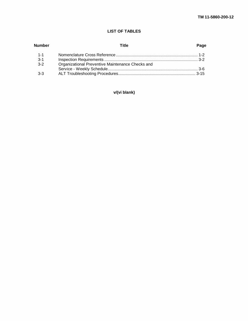
1-1 Nomenclature Cross Reference ...................................................................... 1-23-1 Inspection Requirements ................................................................................ 3-23-2 Organizational Preventive Maintenance Checks and
Service - Weekly Schedule............................................................................. 3-63-3 ALT Troubleshooting Procedures.................................................................. 3-15
v/(vi blank)
TM 11-5860-200-12
CHAPTER 1
INTRODUCTION
Section I. GENERAL INFORMATION
EL8TMO01
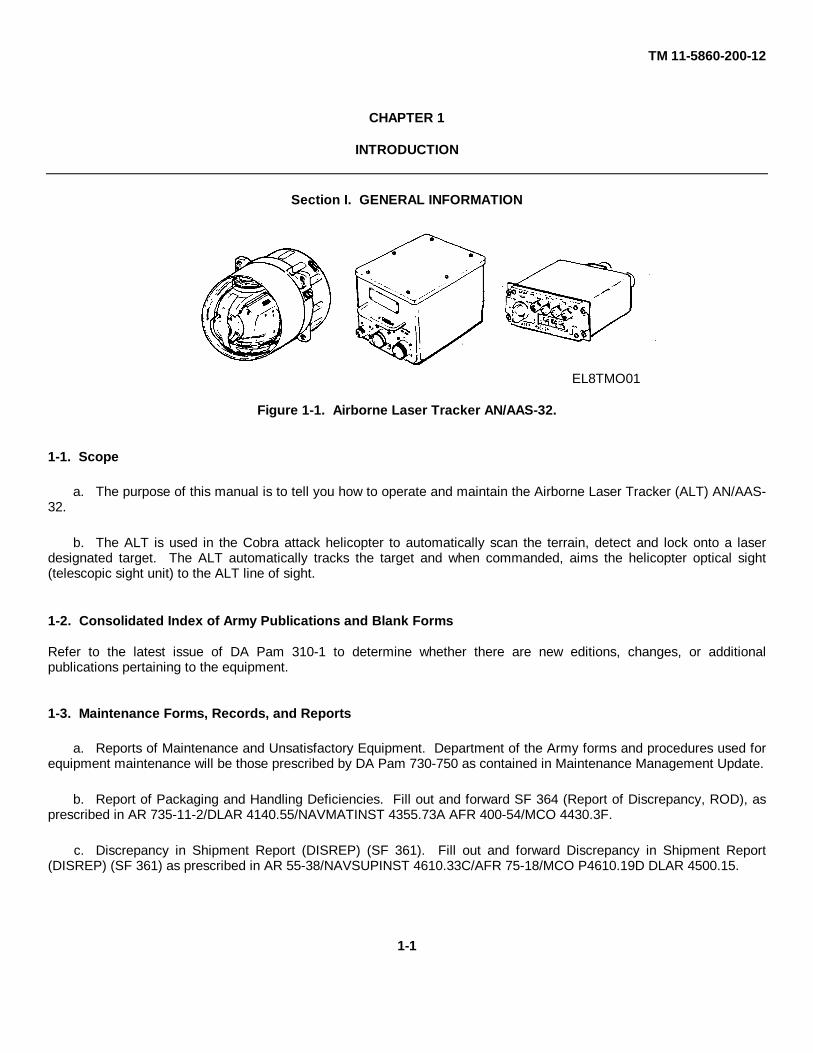
Figure 1-1. Airborne Laser Tracker AN/AAS-32.
1-1. Scope
a. The purpose of this manual is to tell you how to operate and maintain the Airborne Laser Tracker (ALT) AN/AAS-32.
b. The ALT is used in the Cobra attack helicopter to automatically scan the terrain, detect and lock onto a laserdesignated target. The ALT automatically tracks the target and when commanded, aims the helicopter optical sight(telescopic sight unit) to the ALT line of sight.
1-2. Consolidated Index of Army Publications and Blank Forms
Refer to the latest issue of DA Pam 310-1 to determine whether there are new editions, changes, or additionalpublications pertaining to the equipment.
1-3. Maintenance Forms, Records, and Reports
a. Reports of Maintenance and Unsatisfactory Equipment. Department of the Army forms and procedures used forequipment maintenance will be those prescribed by DA Pam 730-750 as contained in Maintenance Management Update.
b. Report of Packaging and Handling Deficiencies. Fill out and forward SF 364 (Report of Discrepancy, ROD), asprescribed in AR 735-11-2/DLAR 4140.55/NAVMATINST 4355.73A AFR 400-54/MCO 4430.3F.
c. Discrepancy in Shipment Report (DISREP) (SF 361). Fill out and forward Discrepancy in Shipment Report(DISREP) (SF 361) as prescribed in AR 55-38/NAVSUPINST 4610.33C/AFR 75-18/MCO P4610.19D DLAR 4500.15.
1-1

TM 11-5860-200-12
1-4. Destruction of Army Materiel to Prevent Enemy Use
Destruction of Army electronics materiel to prevent enemy use shall be in accordance with TM 750-244-2.
1-5. Preparation for Storage or Shipment
Before storing or shipping ALT equipment, preventive maintenance checks and services (PMCS) must be performed.These procedures are outlined in paragraph 2-2. Packing of equipment for shipment or limited storage is provided inparagraphs 3-25, 3-26, and 3-27.
1-6. Reporting Equipment Improvement Recommendations (EIR)
If your ALT needs improvement, let us know. Send us an EIR. You, the user, are the only one who can tell us what youdon't like about your equipment. Let us know why you don't like the design or performance. Put it on an SF 368 (QualityDeficiency Report). Mail it to Commander, US Army Communications - Electronics Command and Fort Monmouth.ATTN: DRSEL-ME-MP, Fort Monmouth, New Jersey 07703. We'll send you a reply.
1-7. Nomenclature Cross-Reference List
Official and common nomenclature is listed in table 1-1.
Table 1-1. Nomenclature Cross-Reference List
Official Nomenclature Common Name
Airborne Laser Tracker AN/AAS-32 ALT
Receiver-Tracker, Laser ReceiverR-1920/AAS-32
Electronic Components Assembly Electronics assemblyMX-9623/AAS-32
Control, Laser Tracker C-9641/AAS-32 Control panel
Mount, Receiver-Tracker Receiver mountMT-4698/AAS-32
Case, Electronic Components Control Electronic assembly panelCY-7441/AAS-32 control transit case
Simulator, Laser SM-706/AAM-56 Laser Simulator
1-2

TM 11-5860-200-12
Section II. EQUIPMENT DESCRIPTION
1-8. Equipment Characteristics, Features, and Capabilities
a. Characteristics and features of the Airborne Laser Tracker are as follows:
(1) All weather operational.
(2) Receiver may be replaced without performing additional boresighting and alignment procedures.
(3) Automatic terrain scanning, target acquisition, and target tracking.
(4) Upon command, aims the helicopter's optical sight (telescopic sight unit).
b. Contains self-test circuits (built-in test equipment).
1-9. Equipment Data
PRIMARY POWER REQUIREMENTS
DC power 28 vdc, 5.0 AAC power 115 vac, 400 Hz, 0.25 A
ENVIRONMENTAL OPERATING RANGESTemperature -50° to 131° FHumidity 0 to 100%Altitude 15,000 ft maximum
INSTANTANEOUS FIELD OF VIEWRectangular, 20 degrees in azimuth,by 10 degrees in elevation
LASER SEEKER COVERAGE(gimbal coverage)
30 degrees (up)60 degrees (down)90 degrees (left)90 degrees (right)
1-3
TM 11-5860-200-12
SCAN COVERAGE
SCAN 1 0 and -8.3 degrees elevation, ±15degrees azimuth
SCAN 2 0 to -25 degrees elevation (0, -8.3,-16.6, and -25 degrees)±60 degrees azimuth
DIMENSIONS (in inches)
Receiver Length: 8.892Diameter: 8.000
Electronics Assembly Length: 8.740Width: 6.240Height: 5.960
Control Panel Length: 6.370Width: 5.750Height: 2.620
WEIGHT (in lbs)Receiver 20.00Electronics Assembly 7.50Control Panel 1.25Receiver Mount 2.75Total 31.50
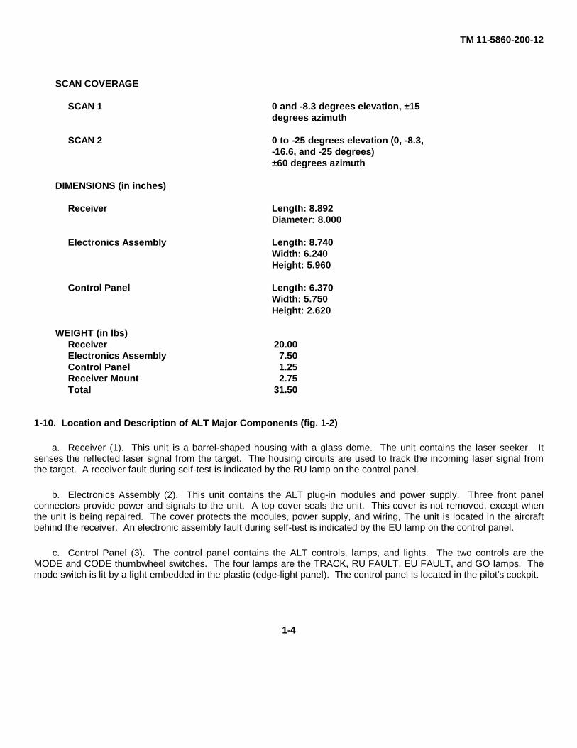
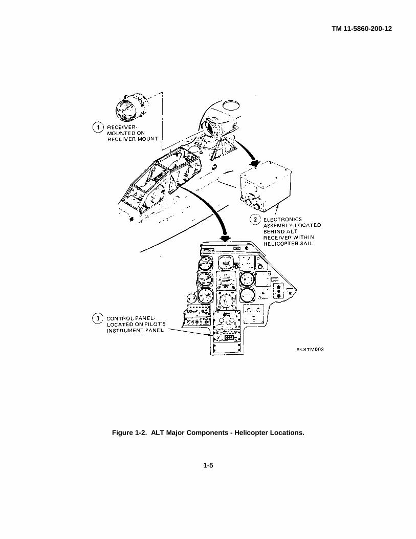
1-10. Location and Description of ALT Major Components (fig. 1-2)
a. Receiver (1). This unit is a barrel-shaped housing with a glass dome. The unit contains the laser seeker. Itsenses the reflected laser signal from the target. The housing circuits are used to track the incoming laser signal fromthe target. A receiver fault during self-test is indicated by the RU lamp on the control panel.
b. Electronics Assembly (2). This unit contains the ALT plug-in modules and power supply. Three front panelconnectors provide power and signals to the unit. A top cover seals the unit. This cover is not removed, except whenthe unit is being repaired. The cover protects the modules, power supply, and wiring, The unit is located in the aircraftbehind the receiver. An electronic assembly fault during self-test is indicated by the EU lamp on the control panel.
c. Control Panel (3). The control panel contains the ALT controls, lamps, and lights. The two controls are theMODE and CODE thumbwheel switches. The four lamps are the TRACK, RU FAULT, EU FAULT, and GO lamps. Themode switch is lit by a light embedded in the plastic (edge-light panel). The control panel is located in the pilot's cockpit.
1-4
TM 11-5860-200-12
Figure 1-2. ALT Major Components - Helicopter Locations.
1-5

TM 11-5860-200-12
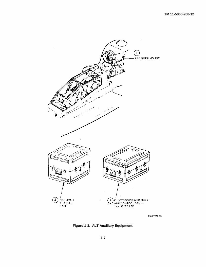
1-11. Location and Description of Ancillary Equipment (fig. 1-3)
The following ancillary equipment is used with the ALT, but is not part of Airborne Laser Tracker AN/AAS-32.
a. Receiver Mount (1). This unit holds the receiver. It is located between the receiver and the aircraft bulkhead.The mount contains connectors which provide contact between the receiver and the electronics assembly.
b. Electronics Assembly and Control Panel Transit Case (2). This case stores the control panel and electronicsassembly when removed from the aircraft. The case is used during transport of these units.
c. Receiver Transit Case (3). This case stores the receiver when it is not in the aircraft. The case is used duringreceiver transport.
1-6
TM 11-5860-200-12
Figure 1-3. ALT Auxiliary Equipment.
1-7

TM 11-5860-200-12
Section III. TECHNICAL PRINCIPLES OF OPERATION
1-12. Operating Principles
The ALT is designed to reduce the time needed by helicopter crews to sight, aim and fire air-to-ground weapons. TheALT relies upon a target spotter (a soldier on the battlefield itself or in another helicopter) who, equipped with a laserdesignator, can train a coded laser beam on the target. The ALT on board the attack helicopter uses a receiver that candetect low level energy reflecting from the laser spot. The ALT scans the terrain, finds and tracks the target. and itsoutput can be used to aim the helicopter's optical sight (telescopic sight unit).
Figure 1-4. ALT Operating Principle.
1-8
TM 11-5860-200-12
CHAPTER 2
OPERATING INSTRUCTIONS
Section I. DESCRIPTION AND USE OF OPERATOR'SCONTROLS AND INDICATORS
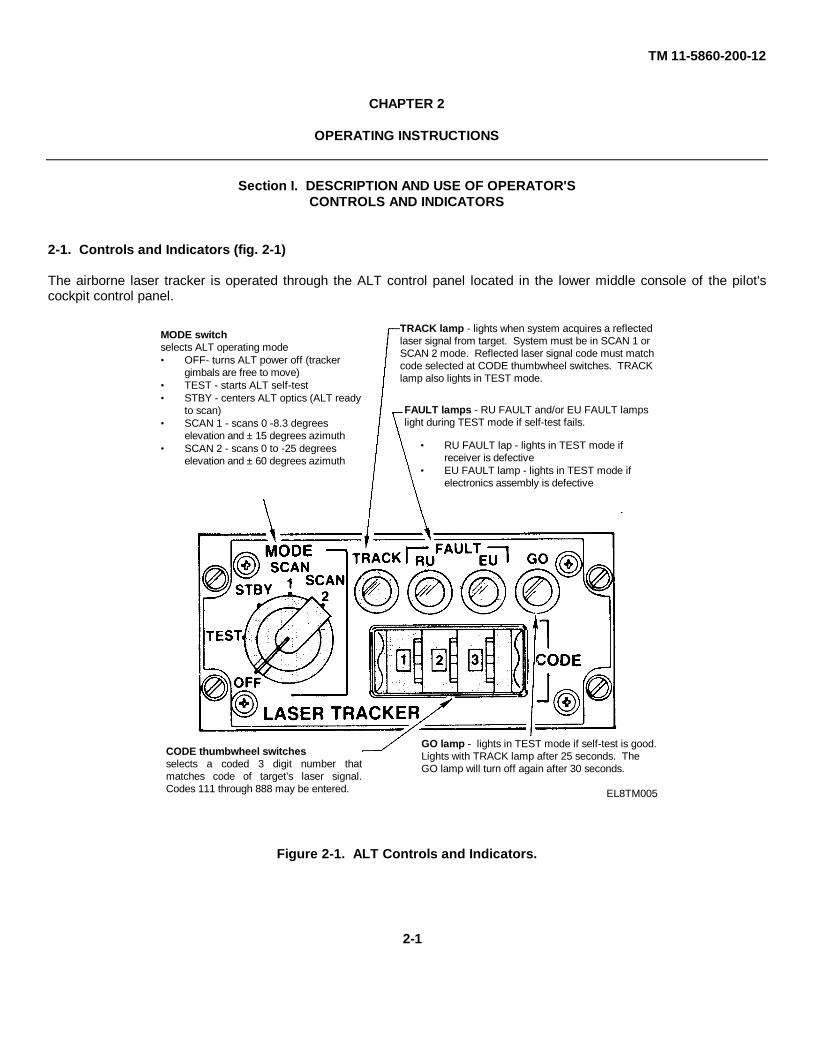
2-1. Controls and Indicators (fig. 2-1)
The airborne laser tracker is operated through the ALT control panel located in the lower middle console of the pilot'scockpit control panel.
Figure 2-1. ALT Controls and Indicators.
MODE switchselects ALT operating mode• OFF- turns ALT power off (tracker
gimbals are free to move)• TEST - starts ALT self-test• STBY - centers ALT optics (ALT ready
to scan)• SCAN 1 - scans 0 -8.3 degrees
elevation and ± 15 degrees azimuth• SCAN 2 - scans 0 to -25 degrees
elevation and ± 60 degrees azimuth
TRACK lamp - lights when system acquires a reflectedlaser signal from target. System must be in SCAN 1 orSCAN 2 mode. Reflected laser signal code must matchcode selected at CODE thumbwheel switches. TRACKlamp also lights in TEST mode.
FAULT lamps - RU FAULT and/or EU FAULT lampslight during TEST mode if self-test fails.
• RU FAULT lap - lights in TEST mode ifreceiver is defective
• EU FAULT lamp - lights in TEST mode ifelectronics assembly is defective
CODE thumbwheel switchesselects a coded 3 digit number thatmatches code of target’s laser signal.Codes 111 through 888 may be entered.
GO lamp - lights in TEST mode if self-test is good.Lights with TRACK lamp after 25 seconds. TheGO lamp will turn off again after 30 seconds.
EL8TM005
2-1

TM 11-5860-200-12
Section II. OPERATOR PREVENTIVE MAINTENANCE CHECKS AND SERVICES (PMCS)
2-2. Operator Preventive Maintenance Checks and Services
a. Before you operate. Perform visual inspection.
b. While you operate. No PMCS required.
c. After you operate. No PMCS required.
d. If your equipment fails to operate. Refer to higher category of maintenance.
2-3. Routine Checks and Services
Routine checks and services are not performed during operator PMCS. As a matter of routine, the following checksshould be performed by you:
• Check for dented, bent, or broken components. • Check for loose mounting of components. • Check for cut or frayed cables. • Check for broken control knobs, switches, and lamp lenses.
2-2
TM 11-5860-200-12
Section III. OPERATION UNDER USUAL CONDITIONS
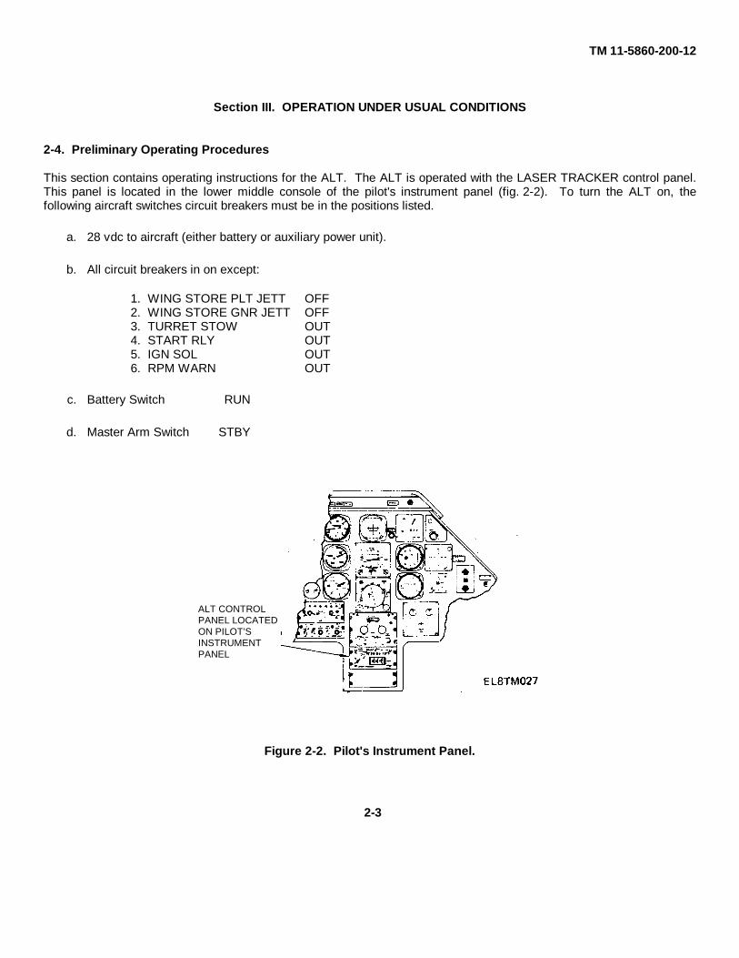
2-4. Preliminary Operating Procedures
This section contains operating instructions for the ALT. The ALT is operated with the LASER TRACKER control panel.This panel is located in the lower middle console of the pilot's instrument panel (fig. 2-2). To turn the ALT on, thefollowing aircraft switches circuit breakers must be in the positions listed.
a. 28 vdc to aircraft (either battery or auxiliary power unit).
b. All circuit breakers in on except:
1. WING STORE PLT JETT OFF2. WING STORE GNR JETT OFF3. TURRET STOW OUT4. START RLY OUT5. IGN SOL OUT6. RPM WARN OUT
c. Battery Switch RUN
d. Master Arm Switch STBY
Figure 2-2. Pilot's Instrument Panel.
ALT CONTROLPANEL LOCATEDON PILOT’SINSTRUMENTPANEL
2-3
TM 11-5860-200-12
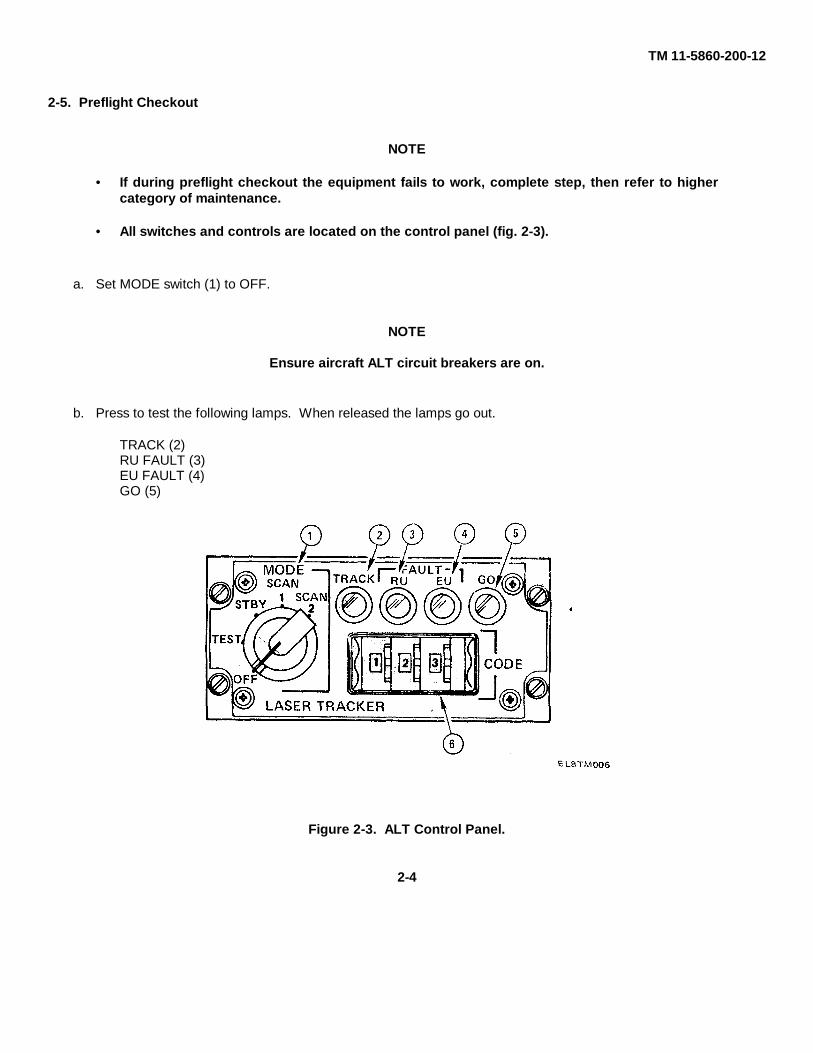
2-5. Preflight Checkout
NOTE • If during preflight checkout the equipment fails to work, complete step, then refer to higher
category of maintenance. • All switches and controls are located on the control panel (fig. 2-3).
a. Set MODE switch (1) to OFF.
NOTE
Ensure aircraft ALT circuit breakers are on.
b. Press to test the following lamps. When released the lamps go out.
TRACK (2)RU FAULT (3)EU FAULT (4)GO (5)
Figure 2-3. ALT Control Panel.
2-4

TM 11-5860-200-12
c. Set CODE switch (6) to desired code.
NOTE
• If RU FAULT (3) or EU FAULT (4) lamps light in TEST mode, rotate MODE switch to STBY andback to TEST. If either RU FAULT or EU FAULT lamps light again, refer to higher category ofmaintenance.
• TRACK lamp (2) may light a few times in TEST mode.
d. Set MODE switch (1) to TEST.
e. Wait about 25 seconds until GO lamp (5) and track lamp (2) lights.
f. The GO lamp (5) goes off after about 30 seconds.
2-5/(2-6 blank)

TM 11-5860-200-12
CHAPTER 3
ORGANIZATIONAL MAINTENANCE
Section I. REPAIR PARTS, SPECIAL TOOLS; TEST,MEASUREMENT, AND DIAGNOSTIC EQUIPMENT (TMDE) AND
SUPPORT EQUIPMENT
3-1. Common Tools And Equipment
For authorized common tools and equipment, refer to the Modified Table of Organization and Equipment (MTOE)applicable to your unit.
3-2. Special Tools, TMDE, And Support Equipment
Special tools, TMDE, and support equipment are listed in Appendix B.
3-3. Repair Parts
Repair parts are listed and shown in the Organizational and Direct Support, Maintenance Repair Parts and Special ToolsList, TM 11-5860-200-23P.
Section II. SERVICE UPON RECEIPT
3-4. General
The ALT is packaged in two transit cases when not installed in the aircraft. These transit cases protect ALT componentsduring storage and transport (fig. 3-1). Inspect ALT equipment upon receipt (table 3-1).
Figure 3-1. ALT Transit Cases.
3-1
TM 11-5860-200-12
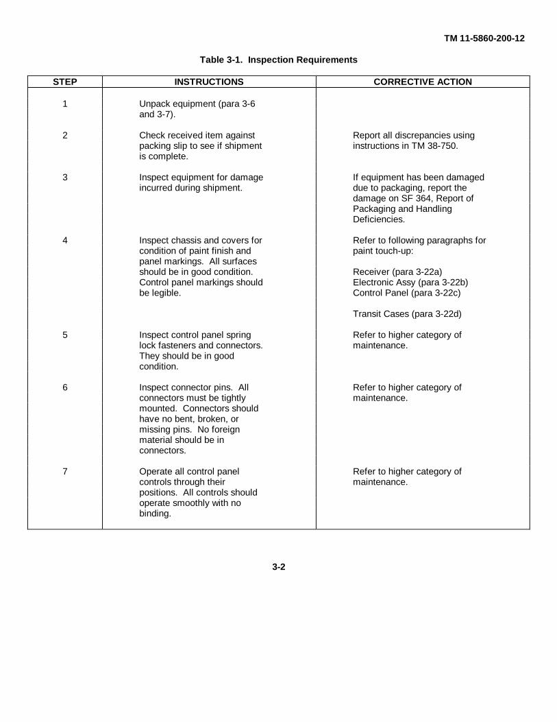
Table 3-1. Inspection Requirements
STEP INSTRUCTIONS CORRECTIVE ACTION
1 Unpack equipment (para 3-6and 3-7).
2 Check received item against Report all discrepancies usingpacking slip to see if shipment instructions in TM 38-750.is complete.
3 Inspect equipment for damage If equipment has been damagedincurred during shipment. due to packaging, report the
damage on SF 364, Report ofPackaging and HandlingDeficiencies.
4 Inspect chassis and covers for Refer to following paragraphs forcondition of paint finish and paint touch-up:panel markings. All surfacesshould be in good condition. Receiver (para 3-22a)Control panel markings should Electronic Assy (para 3-22b)be legible. Control Panel (para 3-22c)
Transit Cases (para 3-22d)
5 Inspect control panel spring Refer to higher category oflock fasteners and connectors. maintenance.They should be in goodcondition.
6 Inspect connector pins. All Refer to higher category ofconnectors must be tightly maintenance.mounted. Connectors shouldhave no bent, broken, ormissing pins. No foreignmaterial should be inconnectors.
7 Operate all control panel Refer to higher category ofcontrols through their maintenance.positions. All controls shouldoperate smoothly with nobinding.
3-2

TM 11-5860-200-12
3-5. Checking Unpacked Equipment
a. Inspect the equipment for damage incurred during shipment. If the equipment has been damaged, report thedamage on SF 364, Report of Discrepancy.
b. Check the equipment against the packing slip to see if the shipment is complete. Report all discrepancies inaccordance with the instructions in TM 38-750. The equipment should be placed in service even though a minorassembly or part that does not affect proper functioning is missing.
c. Check the equipment for modification. Equipment which has been modified will have an MWO number on frontpanel, near the nameplate.
d. Check to see whether all current MWO's have been applied. (Current MWO's applicable to equipment are listedin DA Pam 310-1.)
3-6. Unpacking the Electronics Assembly, Control Panel, or Technical Manual (fig. 3-2)
a. Release pressure equalizer valve (3).
b. Unhook latches (2) securing transit case lid (1).
c. Lift transit case lid (1) from base (4).
d. Lift component, as required, from case.
e. Replace lid (1) on base (4), and secure latches (2).
Figure 3-2. Unpacking Electronics Assembly, Control Panel, or Technical Manual.
3-3

TM 11-5860-200-12
3-7. Unpacking the Receiver (fig. 3-3)
CAUTION • Use care when handling receiver. It contains delicate instruments. • The receiver dome is made of glass and should be protected at all times. Do not touch glass
with bare fingers. Use plastic gloves. Skin oils will damage the optical surface.
a. Before releasing latches and opening the lid, press the pressure equalizer valve (3) located on the side of thetransit case.
b. Unhook latches (2) securing transit case lid (1).
c. Lift lid carefully from transit case base (4).
d. Remove four bolts and four washers (7) securing receiver (6) to container base (5).
e. Carefully lift receiver (6) from transit case base (4).
f. Install transit case lid (1) on transit case base (4).
g. Secure latches (2).
3-4

TM 11-5860-200-12
Figure 3-3. Unpacking Receiver from Transit Case.
3-5
TM 11-5860-200-12
Section III. ORGANIZATIONAL PREVENTIVE MAINTENANCECHECKS AND SERVICES (PMCS)
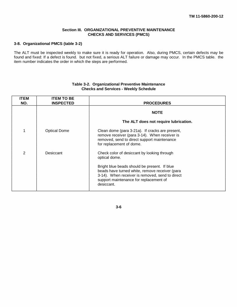
3-8. Organizational PMCS (table 3-2)
The ALT must be inspected weekly to make sure it is ready for operation. Also, during PMCS, certain defects may befound and fixed: If a defect is found. but not fixed, a serious ALT failure or damage may occur. In the PMCS table. theitem number indicates the order in which the steps are performed.
Table 3-2. Organizational Preventive MaintenanceChecks and Services - Weekly Schedule
ITEM ITEM TO BENO. INSPECTED PROCEDURES
NOTE
The ALT does not require lubrication.
1 Optical Dome Clean dome (para 3-21a). If cracks are present,remove receiver (para 3-14). When receiver isremoved, send to direct support maintenancefor replacement of dome.
2 Desiccant Check color of desiccant by looking throughoptical dome.
Bright blue beads should be present. If bluebeads have turned white, remove receiver (para3-14). When receiver is removed, send to directsupport maintenance for replacement ofdesiccant.
3-6

TM 11-5860-200-12
Section IV. ORGANIZATIONAL TROUBLESHOOTINGPROCEDURES
3-9. ALT Troubleshooting Procedures
This section contains troubleshooting information for the ALT. The following self-test and slewing procedure will assist inlocating and correcting ALT operating faults. If any faults occur in self-test, refer to troubleshooting (table 3-3). Repeatself-test if any ALT components are replaced.
NOTE
For ALT turn on, refer to chapter 2, para 2-4.
3-10. Self-Test
Perform self-test on ALT control panel (fig. 3-4) in aircraft as follows:
Figure 3-4. ALT Control Panel.
NOTE
Release lenses after lamp lights.
a. Press-to-test the following lens: TRACK (2), RU FAULT (3), EU FAULT (4), and GO (5).
3-7

TM 11-5860-200-12
NOTE
• If RU FAULT or EU FAULT lamp lights in TEST mode, rotate MODE switch to STBYand back to TEST. If either fault lamp lights again, refer to table 3-3.
• TRACK lamp (2) may light a few times during TEST mode.
b. Set MODE switch (1) to TEST.
c. Wait about 25 seconds until GO lamp (5) and TRACK lamp (2) lights.
d. Set MODE switch (1) to STBY. Check that TRACK lamp (2) goes out, and GO lamp (5) will turn off after about30 seconds.
Figure 3-5. ALT Control Panel.
3-8

TM 11-5860-200-12
3-11. ALT/Telescopic Sight Unit (TSU) Slewing Procedure
The following ALT slewing procedure will determine that the ALT can command (slew) the TSU. If any faults occurduring slewing, refer to table 3-3.
NOTE
This procedure will require three persons. Two will remain in aircraft. Another will standapproximately 15 feet in front of aircraft holding laser simulator at eye level.
a. Turn on ALT (para 2-4).
b. Set MODE switch (1) on control panel (fig. 3-6) to STBY.
c. Set CODE thumbwheel switches (6) on control panel to 111.
d. Set MODE switch (1) on control panel to SCAN 2.
Figure 3-6. ALT Control Panel.
e. Energize the TSU (refer to TM 55-1520-236-10 or TM 55-1520-239-23-1).
3-9

TM 11-5860-200-12
WARNING
The light source from the laser simulator is an infrared light source. The light beam is invisibleto the naked eye. The lens should not be viewed directly to prevent possible eye damage.
CAUTION
Do not touch the lens with bare fingers. Skin oils will damage the optical surface.
f. Place mode switch (1) on laser simulator to HI position (fig. 3-7).
NOTE
Simulator has a narrow beam and must be manipulated carefully in step g below to obtain ALTtrack.
g. Stand 15 feet (approximately) in front of aircraft, and point laser simulator's lens assembly toward ALT receiverin aircraft.
Figure 3-7. Laser Simulator.
3-10

TM 11-5860-200-12
h. Visually ensure that ALT enters track (the ALT should stop scanning and point towards operator).
i. Set CODE thumbwheel switches on control panel to 112.
j. Verify that ALT starts scanning again.
k. Return CODE thumbwheel switches on control panel to 111, and verify that ALT reenters track.
I. Set CODE thumbwheel switches (6) on control panel to 688.
m. Ensure MODE switch (1) on control panel is at SCAN 2.
Figure 3-8. ALT Control Panel.
3-11

TM 11-5860-200-12
WARNING
The light source from the laser simulator is an infrared light source. The light beam is invisibleto the naked eye. The lens should not be viewed directly to prevent possible eye damage.
CAUTION
Do not touch the lens with bare fingers. Skin oils will damage the optical surface.
n. Place mode switch (1) on laser simulator to LO position (fig. 3-9).
NOTE
Simulator has a narrow beam and must be manipulated carefully in step o below to obtain ALT track.
o. Point laser simulator's lens assembly toward ALT receiver in aircraft.
Figure 3-9. Laser Simulator.
3-12

TM 11-5860-200-12
p. Visually ensure that ALT enters track (the ALT should stop scanning and point towards operator).
q. Set CODE thumbwheel switches on control panel to 687.
r. Verify that ALT starts scanning again.
s. Return CODE thumbwheel switches on control panel to 688, and verify that ALT reenters track.
WARNING
Do not view laser simulator through TSU, as possible eye damage could occur.
t. Place ACQ (acquire) switch (fig. 3-10) located on gunner's instrument panel to ALT position.
Figure 3-10. ACQ Switch Location.
3-13

TM 11-5860-200-12
NOTE
• In step u below the ALT may break track. If this occurs, stop walking, realign lasersimulator's lens assembly with ALT receiver. Then continue walking.
• The distance between B and A or C and A in step u below is approximately 27 feet.
u. With laser simulator lens pointed at ALT receiver, walk in an arc, from position A to B, and back to position C(fig. 3-11).
v. Ensure that TSU follows laser simulator by watching (from outside of the helicopter) the TSU move toward thelaser simulator.
w. Turn all equipment off.
Figure 3-11. ALT/TSU Slewing.
3-14

TM 11-5860-200-12
Table 3-3. ALT Troubleshooting Procedures.
SYMPTOM POSSIBLE CAUSE CORRECTIVE ACTION
Press-to-test lamps do No lamp circuit power. Ensure aircraft switchesnot light when pressed are in proper positionon control panel. (para 2-4).
Defective lamps. Replace lamps (para 3-20a).
RU FAULT lamp on Connectors on receiver Check security andcontrol panel lights and boresight mount proper mating of con-during TEST mode. may not be properly nectors.
mated.
Failure in receiver. Replace receiver (para3-14 and 3-15).
Failure in electronics Replace electronicsassembly. assembly (para 3-16 and 3-17).
EU FAULT lamp on Connectors on electron- Check security andcontrol panel lights ics assembly not prop- proper mating of con-during TEST mode. erly mated. nectors.
Failure in electronics Replace electronicsassembly. assembly (para 3-16 and 3-17).
Failure in receiver. Replace receiver(para 3-14 and 3-15).
RU FAULT, EU FAULT Failure in electronics Replace electronicsand GO lamps on con- assembly. assembly (para 3-16 and 3-17).trol panel do not light
Failure in receiver Replace receiverassembly (check gimbal (para 3-14 and 3-15).freedom).
3-15

TM 11-5860-200-12
Table 3-3. ALT Troubleshooting Procedures - Continued.
SYMPTOM POSSIBLE CAUSE CORRECTIVE ACTION
GO lamp lights in Failure in control panel. Replace control panelTEST mode, but sys- (para 3-18 and 3-19).tem (ALT) will not scanor track.
RU FAULT or EU Laser operating in equip- Stop laser operation ifFAULT lamp lights and ment field of view. possible and repeat self-TRACK lamp stays on test.during TEST mode.
Failure in receiver. Replace receiver(para 3-14 and 3-15).
TSU fails to track ALT. Failure in receiver. a. Perform self-test (para 3-10).
b. Replace receiver ifrequired (para 3-14 and 3-15).
Failure in electronics a. Perform self-test (para 3-10).assembly.
b. Replace electronicsassembly (para 3-16 and 3-17).
Failure in interfacing sys- Refer to higher categorytems. of maintenance.
ALT tracks laser with Failure in electronics Replace electronicsdifferent code. assembly. assembly (para 3-16 and 3-17).
Failure in receiver. Replace receiver(para 3-14 and 3-15).
3-16

TM 11-5860-200-12
Table 3-3. ALT Troubleshooting Procedures - Continued.
SYMPTOM POSSIBLE CAUSE CORRECTIVE ACTION
TRACK light on con- Failure in electronics Replace electronicstrol panel lights with assembly. assembly (para 3-16 and 3-17).no laser input, duringSCAN MODE.
Failure in receiver. Replace receiver(para 3-14 and 3-15).
Receiver platform Failure in receiver. Replace receiverdoes not move at all. (para 3-14 and 3-15).
Failure in electronics Replace electronicsassembly. assembly (para 3-16 and 3-17).
3-17

TM 11-5860-200-12
Section V. REMOVAL AND INSTALLATION PROCEDURES
3-12. Gaining Access to Receiver and Electronics Assembly (fig. 3-12).
WARNING
• Do not work on or near forward pylon fairing assembly until helicopter rotor stops turning.
• Ensure aircraft battery is disconnected before installing or removing any ALT component.Death or serious injury could result if aircraft battery remains connected.
NOTE
When removing the forward pylon fairing assembly, do not disconnect the static pressure linefrom pitot tube.
a. Disconnect attaching hardware from forward pylon fairing assembly (1) with the exception of the pitot tubestatic pressure line (refer to TM 55-1520-236-20 or TM 55-1520-239-23-1).
b. Disconnect electrical connector at bulkhead from pitot tube (2) heater system.
c. Pull forward pylon fairing assembly (1) forward enough to remove clamp holding pitot tube heater wires, andstatic pressure line forward lower clamp.
d. Place forward pylon fairing assembly on canopy using care not to damage static pressure line.
3-13. Installing Forward Pylon Fairing Assembly (fig. 3-12).
WARNING
• Do not work on or near forward pylon fairing assembly until helicopter rotor stops turning.
• Ensure aircraft battery is disconnected before installing or removing any ALT component.Death or serious injury could result if aircraft battery remains connected.
a. Connect electrical connector to pitot tube (2) heater system.
3-18

TM 11-5860-200-12
b. Install the static pressure line forward bottom clamp, and clamp holding pitot tube heater wires.
c. Connect forward pylon fairing assembly (1) (refer to TM 55-1520-236-20 or TM 55-1520-239-23-1).
Figure 3-12. Receiver and Electronics Assembly Access Locations.
3-19

TM 11-5860-200-12
3-14. Removal of Receiver from Helicopter (fig. 3-13).
Figure 3-13. Removal and Replacement of Receiver from Helicopter.
WARNING
• Do not work on or near forward pylon fairing assembly until helicopter rotor stops turning.
• Ensure aircraft battery is disconnected before installing or removing any ALT component.Death or serious injury could result if aircraft battery remains connected.
CAUTION
Use care when handling receiver. It contains delicate instruments. The receiver dome is made ofglass and should be protected at all times. Do not touch glass with bare fingers. Use plasticgloves. Skin oils will damage the optical surface.
a. Gain access to receiver and electronics assembly (para 3-12).
3-20
TM 11-5860-200-12
b. Remove the four mounting bolts and washers from pads (2) that secure receiver to receiver mount (1). Holdreceiver firmly to prevent dropping.
c. Pull receiver straight out from mount.
CAUTION
The receiver shall not be transported without first being installed in the transit case (para 3-26) ordamage to the receiver will occur.
3-15. Installation of Receiver into Helicopter (fig. 3-13).
CAUTION
Use care when handling receiver. It contains delicate instruments. The receiver dome is made ofglass and should be protected at all times. Do not touch glass with bare fingers. Use plasticgloves. Skin oils will damage the optical surface.
a. Remove receiver from transit case (para 3-7).
WARNING
• Do not work on or near forward pylon fairing assembly until helicopter rotor stops turning.
• Ensure aircraft battery is disconnected before installing or removing any ALT component.Death or serious injury could result if aircraft battery remains connected.
b. Lift receiver carefully to pads (2) on receiver mount guiding the mount's alignment pins into receiver's matingholes.
c. Ensure the two cable connectors are properly aligned to back of receiver.
d. Hold receiver in place. Install four bolts and washers through receiver mounting flanges to secure receiver toreceiver mount.
e. Torque receiver mounting bolts to 90 ± 10 inch-pounds.
f. Install forward pylon fairing assembly (para 3-13).
3-21
TM 11-5860-200-12
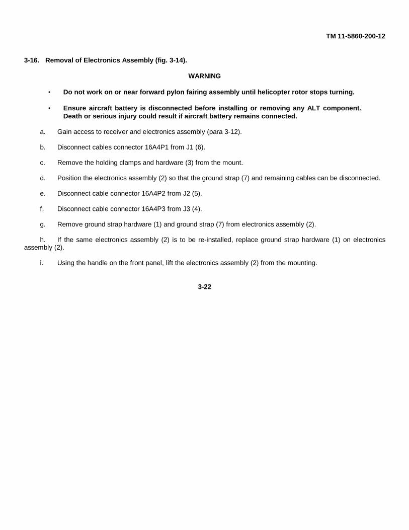
3-16. Removal of Electronics Assembly (fig. 3-14).
WARNING
• Do not work on or near forward pylon fairing assembly until helicopter rotor stops turning.
• Ensure aircraft battery is disconnected before installing or removing any ALT component.Death or serious injury could result if aircraft battery remains connected.
a. Gain access to receiver and electronics assembly (para 3-12).
b. Disconnect cables connector 16A4P1 from J1 (6).
c. Remove the holding clamps and hardware (3) from the mount.
d. Position the electronics assembly (2) so that the ground strap (7) and remaining cables can be disconnected.
e. Disconnect cable connector 16A4P2 from J2 (5).
f. Disconnect cable connector 16A4P3 from J3 (4).
g. Remove ground strap hardware (1) and ground strap (7) from electronics assembly (2).
h. If the same electronics assembly (2) is to be re-installed, replace ground strap hardware (1) on electronicsassembly (2).
i. Using the handle on the front panel, lift the electronics assembly (2) from the mounting.
3-22

TM 11-5860-200-12
Figure 3-14. Removal of Electronics Assembly.
3-23

TM 11-5860-200-12
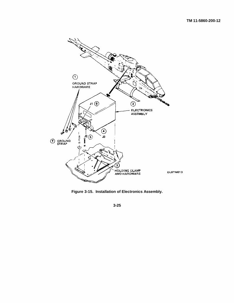
3-17. Installation of Electronics Assembly (fig. 3-15).
WARNING
• Do not work on or near forward pylon fairing assembly until helicopter rotor stops turning.
• Ensure aircraft battery is disconnected before installing or removing any ALT component.Death or serious injury could result if aircraft battery remains connected.
a. Gain access to receiver and electronics assembly (para 3-12).
b. Remove electronics assembly (2) from transit case (para 3-6).
c. Remove two holding clamps and hardware (3) from aircraft.
d. Place the electronic assembly on the mount in a position that will allow the ground strap (7) and cables to J2(5) and J3 (4) to be connected.
e. Connect ground strap (7) to electronics assembly (2) (in 10 o’clock position) using ground strap hardware (1).
f. Connect cable connector 16A4P3 to J3 (4).
g. Connect cable connector 16A4P2 to J2 (5).
h. Place the electronics assembly (2) on aircraft mounting so that holding clamps and hardware (3) can bereplaced.
i. Install the holding clamps and hardware (3).
j. Connect cable connector 16A4P1 to J1 (6).
k. Install forward pylon fairing assembly on helicopter (para 3-13).
3-24
TM 11-5860-200-12
Figure 3-15. Installation of Electronics Assembly.
3-25
TM 11-5860-200-12
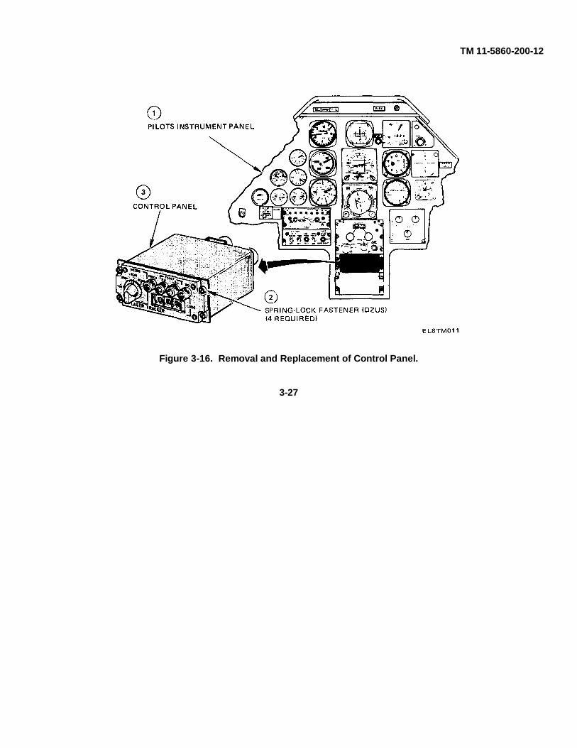
3-18. Removal of Control Panel (fig. 3-16).
WARNING
Ensure aircraft battery is disconnected before installing or removing any ALT component. Deathor serious injury could result if aircraft battery remains connected.
NOTE
Cyclic control stick must be in full aft position.
a. Loosen the four spring-lock fasteners (2) that secure control panel (3) to the pilot's instrument panel (1).
b. Lift the control panel from the instrument panel.
c. Disconnect the two electrical connectors from rear of control panel.
d. Remove control panel.
3-19. Installation of Control Panel (fig. 3-16).
WARNING
Ensure aircraft battery is disconnected before installing or removing any ALT component. Deathor serious injury could result if aircraft battery remains connected.
NOTE
Cyclic control stick must be in full aft position.
a. Connect the two electrical connectors to the rear of control panel.
b. Position control panel (3) in the pilot's instrument panel (1).
c. Secure control panel by tightening the four spring-lock fasteners (2).
3-26
TM 11-5860-200-12
Figure 3-16. Removal and Replacement of Control Panel.
3-27
TM 11-5860-200-12
Section VI. REPAIR, CHECKOUT, SHIPMENT
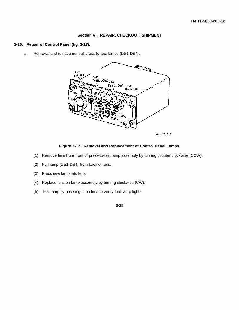
3-20. Repair of Control Panel (fig. 3-17).
a. Removal and replacement of press-to-test lamps (DS1-DS4).
Figure 3-17. Removal and Replacement of Control Panel Lamps.
(1) Remove lens from front of press-to-test lamp assembly by turning counter clockwise (CCW).
(2) Pull lamp (DS1-DS4) from back of lens.
(3) Press new lamp into lens.
(4) Replace lens on lamp assembly by turning clockwise (CW).
(5) Test lamp by pressing in on lens to verify that lamp lights.
3-28

TM 11-5860-200-12
b. Removal and replacement of code switch lamps (fig. 3-18).
(1) Remove control panel from aircraft (para 3-18).
(2) Remove four screws (1) that secure access cover (6).
(3) Remove access cover (6) and gasket (5).
(4) Loosen lamp contact screw (2) and turn lamp contact (3) to side.
(5) Remove lamp (4) from code switch and install new lamp in place.
(6) Turn lamp contact (3) to lamp base (4) and tighten screw (2).
(7) Carefully replace gasket (5) on control panel and install cover (6) in place.
(8) Install four screws (1) that secure access cover (6) in place.
Figure 3-18. Removal and Replacement of Code Switch Lamps.
3-29

TM 11-5860-200-12
c. Remove MODE switch knob (fig. 3-19).
(1) On MODE switch knob (1), loosen setscrew (2).
(2) Remove MODE switch knob (1) from shaft (3).
d. Replace MODE switch knob (fig. 3-19).
(1) Install MODE switch knob (1) on shaft (3).
NOTE
Ensure MODE switch knob is keyed to shaft.
(2) Tighten setscrew (2).
Figure 3-19. Removal and Replacement of Control Panel MODE Switch Knob.
3-30

TM 11-5860-200-12
3-21. Cleaning.
a. Cleaning optical dome.
CAUTION
Do not touch glass with bare fingers, use plastic gloves (item 10, App D). Skin oils will damagethe optical surface. Do not wipe dome with dry materials that may scratch the optical surface.
(1) Remove loose dirt from dome with a clean, dry, soft brush or low pressure stream of clean dry air.
CAUTION
The optical dome shall be cleaned only with authorized cleaning compound, (item 1, App D).Type II cleaning compound can be used at temperatures as low as -40°F. Any other cleaningcompound will damage optical dome.
(2) Lightly wipe the glass surface with a clean, absorbent lint-free cloth (item 4, App D) slightly dampenedwith cleaning compound. Use cleaning compound sparingly.
(3) Wipe dome with another clean, absorbent, lint-free cloth (item 4, App D) until surface is clean.
b. Cleaning control panel and component cases. The following materials are used when cleaning thisequipment:
Materials
Cleaning Compound (item 6, App D)Lint-free cloth (item 4, App D)
Soft-bristled brush (item 7, App D)
(1) Remove dust and dirt using lint-free cloth (item 4, App D) and soft-bristled brush (item 7, App D).
(2) Remove grease, dirt, and fungus from component cases using cloth dampened with cleaning compound(item 6, App D).
(3) Clean front of control panel using lint-free cloth (item 4, App D). If necessary, use damp cloth, then wipewith dry lint-free cloth (item 4, App D).
3-31
TM 11-5860-200-12
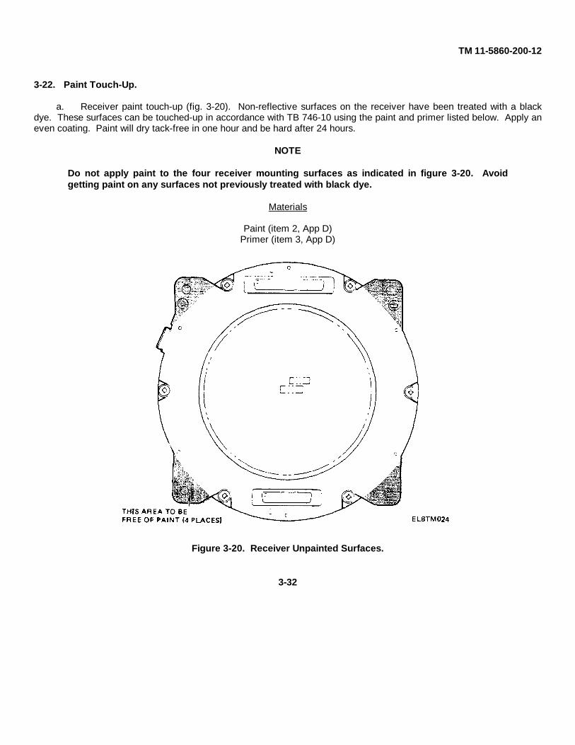
3-22. Paint Touch-Up.
a. Receiver paint touch-up (fig. 3-20). Non-reflective surfaces on the receiver have been treated with a blackdye. These surfaces can be touched-up in accordance with TB 746-10 using the paint and primer listed below. Apply aneven coating. Paint will dry tack-free in one hour and be hard after 24 hours.
NOTE
Do not apply paint to the four receiver mounting surfaces as indicated in figure 3-20. Avoidgetting paint on any surfaces not previously treated with black dye.
Materials
Paint (item 2, App D)Primer (item 3, App D)
Figure 3-20. Receiver Unpainted Surfaces.
3-32

TM 11-5860-200-12
b. Electronic assembly paint touch-up (fig. 3-21). Touch-up chips and scratches on painted surfaces inaccordance with TB 746-10 using paint (item 5, App D).
NOTE
Do not apply paint or primer to any surfaces that were not originally painted.
Figure 3-21. Electronics Assembly Unpainted Surfaces.
c. Control Panel Paint Touch-Up. Touch-up chips and scratches on painted surfaces in accordance with TB 746-10 using paint (item 5, App D).
d. Transit Cases. Touch-up chips and scratches on painted surfaces in accordance with TB 746-10 using thepaint and primer listed below.
Materials
Paint (item 8, App D)Primer, Zinc Chromate (item 9, App D)
3-33

TM 11-5860-200-12
3-23. Lubrication.
The ALT does not require lubrication.
3-24. Checkout.
Operation of the ALT is verified by performing self-test procedures (para 3-10).
3-25. Preparation for Shipment.
When receiving or shipping equipment, always check equipment against the packing slip to see if the shipment iscomplete.
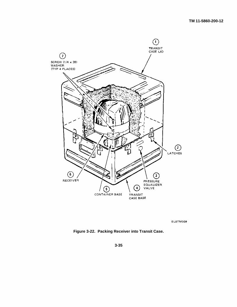
3-26. Packing the Receiver (fig. 3-22).
a. Before releasing latches and opening the lid. press the pressure equalizer (3) valve located on the side of thetransit case.
b. Unhook latches (2) securing transit case lid (1).
c. Lift lid carefully from transit case base (4).
CAUTION
• Use care when handling receiver. It contains delicate instruments.
• The receiver dome is made of glass and should be protected at all times. Do not touchglass with bare fingers. Use plastic gloves (item 10, App D). Skin oils will damage theoptical surface.
d. Carefully lower receiver (6) on container base (5) and secure with four bolts and washers (7).
e. Install transit case lid (1) on transit case base (4).
f. Secure latches (2).
3-34
TM 11-5860-200-12
Figure 3-22. Packing Receiver into Transit Case.
3-35

TM 11-5860-200-12
3-27. Packing the Electronics Assembly, Control Panel, or Technical Manual (fig. 3-23).
a. Before releasing latches and opening the lid. press the pressure equalizer valve (3) located on the side of thetransit case.
b. Unhook latches (2) securing transit case lid (1).
c. Lift transit case lid (1) from base (4).
d. Install component, as required, into case.
e. Replace lid (1) on base (4), and secure latches (2).
Figure 3-23. Packing the Electronics Assembly, Control Panel, or Technical Manual.
3-36

TM 11-5860-200-12
APPENDIX A
REFERENCES
A-1. PUBLICATION INDEXES
Consult indexes for latest changes and revisions to the forms, records, and publications listed in this appendix.
Consolidated Index of Army Publications and Blank Forms......................................................................... DA Pam 310-1
A-2. FORMS AND RECORDS
Recommended Changes to Publications ......................................................................................................DA Form 2028
Discrepancy in Shipment Report (DISREP)............................................................................................................. SF 361
Report of Discrepancy............................................................................................................................................. SF 364
Quality Deficiency Report........................................................................................................................................ SF 368
A-3. GENERAL PUBLICATIONS
Procedures for Destruction of Electronics Materiel to Prevent Enemy Use ................................................... TM 750-244-2
The Army Maintenance Management System (TAMMS) ..........................................................................DA Pam 738-750
Electronics Command Equipment ......................................................................................................................SB 11-573
Federal Supply Codes for Manufacturers ...........................................................................................................SB 708-42
Field Instructions for Painting and Preserving Electronics Command Equipment................................................ TB 746-10
Administrative Storage of Equipment ............................................................................................................. TM 740-90-1
Painting Instructions for Field Use....................................................................................................................... TM 9-213
Organizational and Direct Support Maintenance Repair Parts and Special Tools List ........................ TM 11-5860-200-23P
A-1

TM 11-5860-200-12
Direct Support Maintenance Manual.....................................................................................................TM 11-5860-200-30
Operator's Manual Army Model AH-1S(PROD). AH-1S (ECAS), and AH-1S(Modernized Cobra) Helicopters ...........................................................................................................TM 55-1520-236-10
Operator's Manual Army Model AH-1S (Modernized Cobra) Helicopter ................................................TM 55-1520-239-10
First Aid for Soldiers............................................................................................................................................ FM 21-11
A-2

TM 11-5860-200-12
APPENDIX B
MAINTENANCE ALLOCATION
Section I. INTRODUCTION
B-1. MAINTENANCE ALLOCATION CHART
a. This Maintenance Allocation Chart (MAC) assigns maintenance functions in accordance with the Three Levelsof Maintenance concept for Army aviation. These maintenance levels (categories) - Aviation Unit Maintenance (AVUM),Aviation Intermediate Maintenance (AVIM), and Depot Maintenance - are depicted on the MAC as:
AVUM, which corresponds to a 0 Code in the Repair Parts and Special Tools List (RPSTL).
AVIM, which corresponds to a F code in the Repair Parts and Special Tools List (RPSTL).
DEPOT, which corresponds to a D code in the Repair Parts and Special Tools List (RPSTL).
b. The maintenance to be performed below depot and in the field is described as follows:
(1) Aviation Unit Maintenance (AVUM) activities will be staffed and equipped to perform high frequency “On-Aircraft” maintenance tasks required to retain or return aircraft systems to a serviceable condition. The maintenancecapability of the AVUM will be governed by the Maintenance Allocation Chart (MAC) and limited by the amount andcomplexity of ground support equipment (GSE), facilities required, authorized manning strength, and critical skillsavailable. The range and quantity of authorized spare modules/components will be consistent with the mobilityrequirements dictated by the air mobility concept. (Assignments of maintenance tasks to divisional company sizeaviation units will consider the overall maintenance capability of the division, the requirement to conserve personnel andequipment resources, and air mobility requirements.)
B-1

TM 11-5860-200-12
(a) Company Size Aviation Units: Perform those tasks which consist primarily of preventivemaintenance and maintenance repair and replacement functions associated with sustaining a high level of aircraftoperational readiness. Perform maintenance inspections and servicing to include preflight, daily, intermediate, periodic(or phased), and special inspections as authorized by the MAC or higher headquarters. Identify the cause ofequipment/system malfunctions using applicable technical manual troubleshooting instructions, built-in test equipment(BITE), installed aircraft instruments, or test, measurement, and diagnostic equipment (TMDE). Replace worn ordamaged modules/components that do not require complex adjustments or system alignment and which can beremoved/installed with available skills, tools, and ground support equipment. Perform operational and continuity checksand make minor repairs to the electrical system. Inspect, service and make operational, capacity, and pressure checksto hydraulic systems. Perform servicing, functional adjustments, and minor repair/replacement to the flight control,propulsion, power train, and fuel systems. Accomplish air frame repair that does not require extensive disassembly,jigging, or alignment. The manufacture of air frame parts will be limited to those items which can be fabricated with toolsand equipment found in current air mobile tool and shop sets. Evacuate unserviceable modules/components and enditems beyond the repair capability of AVUM to the supporting AVIM.
(b) Less than Company Size Aviation Units: Aviation elements organic to brigade, group, battalionheadquarters, and detachment size units are normally small and have less than ten aircraft assigned. Maintenance tasksperformed by these units will be those which can be accomplished by the aircraft crew chief or assigned aircraftrepairman and will normally be limited to preventive maintenance, inspections, servicing, spot painting, stop drilling,application of non-stress patches, minor adjustments, module/component fault diagnosis, and replacement of selectedmodules/components. Repair functions will normally be accomplished by the supporting AVIM unit.
B-2

TM 11-5860-200-12
(2) Aviation Intermediate Maintenance (AVIM) provides mobile, responsive "One-Stop" maintenance support.(Maintenance functions which are not conducive to sustaining air mobility will be assigned to depot maintenance.) AVIMmay perform all maintenance functions authorized to be done at AVUM. Repair of equipment for return to user willemphasize support or operational readiness requirements. Authorized maintenance includes replacement and repair ofmodules/components and end items which can be accomplished efficiently with available skills, tools, and equipment.AVIM establishes the Direct Exchange (DX) program for AVUM units by repairing selected items for return to stock whensuch repairs cannot be accomplished at the AVUM level. The AVIM level inspects, troubleshoots, performs diagnostictests, repairs, adjusts, calibrates, and aligns aircraft system modules/components. AVIM units will have capability todetermine the serviceability of specified modules/components removed prior to the expiration of the Time BetweenOverhaul (TBO) or finite life. Module/component disassembly and repair will support the DX program and will normallybe limited to tasks requiring cleaning and the replacement of seals, fittings, and items of common hardware. Air framerepair and fabrication of parts will be limited to those maintenance tasks which can be performed with available tools andtest equipment. Unserviceable reparable modules/components and end items which are beyond the capability of AVIMto repair will be evacuated to Depot Maintenance. AVIM will perform aircraft weight and balance inspections and otherspecial inspections which exceed AVUM capability. Provides quick response maintenance support, including aircraftrecovery and air evacuation, on-the-job training, and technical assistance through the use of mobile maintenance contactteams. Maintains authorized operational readiness float aircraft. Provides collection and classification services forserviceable/unserviceable material. Operates a cannibalization activity in accordance with AR 710-2. (The aircraftmaintenance company within the maintenance battalion of a division will perform AVIM functions consistent with airmobility requirements and conservation of personnel and equipment resources. Additional intermediate maintenancesupport will be provided by the supporting nondivisional AVIM unit.)
B-3

TM 11-5860-200-12
B-2. USE OF THE MAINTENANCE ALLOCATION CHART(Section II)
a. The Maintenance Allocation Chart assigns maintenance functions to the lowest category of maintenance basedon past experience and the following considerations:
(1) Skills available.
(2) Work time required.
(3) Tools and test equipment required and/or available.
b. Only the lowest category of maintenance authorized to perform a maintenance function is indicated. If the lowestmaintenance category cannot perform all tasks of any single maintenance function (e.g., test, repair), then the highermaintenance levels that can accomplish additional tasks will also be indicated.
c. A maintenance function assigned to a maintenance category will automatically be authorized to be performed atany higher maintenance category.
d. A maintenance function that cannot be performed at the assigned category of maintenance for any reason maybe evacuated to the next higher maintenance category. Higher maintenance categories will perform the maintenancefunctions of lower maintenance categories when required or directed by the commander that has the authority to directsuch tasking.
e. The assignment of a maintenance function will not be construed as authorization to carry the related repair partsor spares in stock. Information to requisition or otherwise secure the necessary repair parts will be as specified in theassociated Repair Parts and Special Tools List (RPSTL).
f. Normally there will be no deviation from the assigned level of maintenance. In cases of operational necessity,maintenance functions assigned to a maintenance level may, on a one-time basis and at the request of the lowermaintenance level, be specifically authorized by the maintenance officer of the level of maintenance to which thefunction is assigned. The special tools, equipment, etc. required by the lower level of maintenance to perform thisfunction will be furnished by the maintenance level to which the function is assigned. This transfer of a maintenancefunction to a lower maintenance level does not relieve the higher maintenance level of the responsibility for the function.The higher level of maintenance will provide technical supervision and inspection of the function being performed at thelower level.
g. Changes to the Maintenance Allocation Chart will be based on continuing evaluation and analysis by responsibletechnical personnel and on reports received from field activities.
B-4

TM 11-5860-200-12
B-3. MAINTENANCE FUNCTIONS
Maintenance functions will be limited to and defined as follows:
a. Inspect. To determine the serviceability of an item by comparing its physical, mechanical, and/or electricalcharacteristics with established standards through examination (e.g., by sight, sound, or feel).
b. Test. To verify serviceability by measuring the mechanical or electrical characteristics of an item and comparingthose characteristics with prescribed standards.
c. Service. Operations required periodically to keep an item in proper operating condition, i.e., to clean (includesdecontaminate, when required), to preserve, to drain, to paint, or to replenish fuel, lubricants, chemical fluids, or gases.
d. Adjust. To maintain, within prescribed limits, by bringing into proper or exact position, or by setting the operatingcharacteristics to specified parameters.
e. Align. To adjust specified variable elements of an item to bring about optimum or desired performance.
f. Calibrate. To determine and cause corrections to be made or to be adjusted on instruments or test measuringand diagnostic equipment used in precision measurement. Consists of comparisons of two instruments, one of which is acertified standard of known accuracy, to detect and adjust any discrepancy in the accuracy of the instrument beingcompared.
g. Install. To remove and install the same item when required to perform service or other maintenance functions.The act of emplacing, seating, or fixing into position an item, part, or module (component or assembly) in a manner toallow the proper functioning of an equipment or system.
h. Replace. The act of substituting a serviceable like type part, subassembly, or module (component or assembly)for an unserviceable counterpart.
i. Repair. The application of maintenance services (inspect, test, service, adjust, align, calibrate, and/or replace)including fault location/troubleshooting (the process of investigating and detecting the cause of equipmentmalfunctioning; the act of isolating a fault within a system or unit under test; UUT) procedures, and maintenance actions(welding, grinding, riveting, straightening, facing, remachining and/or resurfacing) to identify troubles and restoreserviceability to an item by correcting specific damage, fault, malfunction, or failure in a part, subassembly, module(component or assembly), end item or system.
B-5

TM 11-5860-200-12
j. Overhaul. That maintenance effort (service/action) necessary to restore an item to a completely serviceableoperational condition as prescribed by maintenance standards (i.e., DMWR). Overhaul is normally the highest degree ofmaintenance performed by the Army. Overhaul does not normally return an item to like new condition.
k. Rebuild. Consists of those services/actions necessary for the restoration of unserviceable equipment to a likenew condition in accordance with original manufacturing standards. Rebuild is the highest degree of materielmaintenance applied to Army equipment. The rebuild operation includes the act of returning to zero those agemeasurements (hours, miles, etc.) considered in classifying Army equipments/components.
B-4. FUNCTIONAL GROUPS (Columns 1 and 2)
The functional groupings shown in the sample below identify maintenance significant components, assemblies,subassemblies, and modules with the next higher assembly.
B-5. MAINTENANCE FUNCTION (Column 3)
Column 3 lists the functions to be performed on the items listed in column 2.
B-6. MAINTENANCE CATEGORIES AND WORK TIMES (Column 4)
The maintenance categories (levels) AVUM, AVIM, and DEPOT are listed on the Maintenance Allocation Chart withindividual columns that include the work times for maintenance functions at each maintenance level. Work timepresentations such as "0.1" indicate the average time it requires a maintenance level to perform a specified maintenancefunction. If a work time has not been established, the columnar presentation shall indicate "-.-." Maintenance levelshigher than the level of maintenance indicated are authorized to perform the indicated function.
B-7. TOOLS AND TEST EQUIPMENT (Column 5 and Section III)
Common tool sets (not individual tools), special tools, test, and support equipment required to perform maintenancefunctions are listed alphabetically in Section III with a reference number to permit cross-referencing to column 5 in theMAC. In addition, the maintenance category authorized to use the device is listed along with the item National StockNumber (NSN) and, if applicable, the tool number to aid in identifying the tool/device.
B-8. REMARKS (Column 6 and Section IV)
Remarks (identified by an alphabetic code in column 6) and other notes (identified by a number in parentheses in theapplicable column) are listed in section IV to provide a ready reference to the definition of the remark/note.
B-6

TM 11-5860-200-12
SECTION II. MAINTENANCE ALLOCATION CHARTFOR
AIRBORNE LASER TRACKER AN/AAS-32
(1) (2) (3) (4) (5) (6)MAINTENANCE
CATEGORYGROUP COMPONENT/ MAINTENANCE TOOLS AND
NUMBER ASSEMBLY FUNCTION AVUM AVIM DEPOT EQUIPMENT REMARKS
00 AIRBORNE Inspect 0.1LASER Test 0.1 29 A,LAN/AAS-32 Service 0.3 B
Align 0.5 29 C,LRepair 0.3 1 EInstall 2.0 2,3
01 RECEIVER Replace 0.3 2,3TRACKER Test 0.5 4R-1920/ thruAAS-32 15,
Repair 0.3 2,3 FRepair 7.0 16,17
18,28
0101 PLATFORM Repair 0.3 4ASSY, LASER thru FSEEKER 11,
Repair 4.0 19Align 2.0 19
010101 MOTOR, Repair 3.0 2,3TORQUEASSY, EL
010102 MOTOR, Repair 3.0 2,3TORQUEASSY, AZ
010103 DOME Replace 0.1 1,13,14,15ASSEMBLY Repair 2.0
010104 WIRE Repair 2.0 2,3,10HARNESSBRANCHED(W2)
B-7
TM 11-5860-200-12
SECTION II. MAINTENANCE ALLOCATION CHARTFOR
AIRBORNE LASER TRACKER AN/AAS-32 - Continued
(1) (2) (3) (4) (5) (6)MAINTENANCE
CATEGORYGROUP COMPONENT/ MAINTENANCE TOOLS AND
NUMBER ASSEMBLY FUNCTION AVUM AVIM DEPOT EQUIPMENT REMARKS
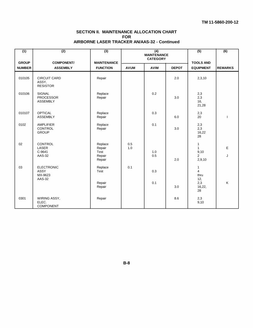
010105 CIRCUIT CARD Repair 2.0 2,3,10ASSY,RESISTOR
010106 SIGNAL Replace 0.2 2,3PROCESSOR Repair 3.0 2,3ASSEMBLY 16,
21,28
010107 OPTICAL Replace 0.3 2,3ASSEMBLY Repair 6.0 20 I
0102 AMPLIFIER Replace 0.1 2,3CONTROL Repair 3.0 2,3GROUP 16,22
28
02 CONTROL Replace 0.5 1LASER Repair 1.0 1 EC-9641 Test 1.0 9,10AAS-32 Repair 0.5 2 J
Repair 2.0 2,9,10
03 ELECTRONIC Replace 0.1 1ASSY Test 0.3 4MX-9623 thruAAS-32 12,
Repair 0.1 2,3 KRepair 3.0 16,22,
28
0301 WIRING ASSY, Repair 8.6 2,3ELEC. 9,10COMPONENT
B-8

TM 11-5860-200-12
SECTION II. MAINTENANCE ALLOCATION CHARTFOR
AIRBORNE LASER TRACKER AN/AAS-32 - Continued
(1) (2) (3) (4) (5) (6)MAINTENANCE
CATEGORYGROUP COMPONENT/ MAINTENANCE TOOLS AND
NUMBER ASSEMBLY FUNCTION AVUM AVIM DEPOT EQUIPMENT REMARKS
0302 POWER SUPPLY Replace 0.1 2Repair 2.5 2,3
27,28
0303 CIRCUIT CARD Replace 0.1 2ASSY, LOGIC Repair 2.5 2,3
16,26,28
0304 AMPLIFIER Replace 0.1 2CONTROL Repair 2.5 2,3,GROUP, SERVO 16,25,INTERFACE 28
0305 CIRCUIT CARD Replace 0.1 2ASSY, BITE Repair 2.5 2,3,
16,2428
0306 CIRCUIT CARD Replace 0.1 2ASSY, DE- Repair 2.5 2,3,CODER CMD., 16,23,SIGNAL DRF 28
04 MOUNT, Replace 0.2 2RECEIVER Repair 0.2 1 HTRACKERMT-4698/AAS-32
05 CASE, Replace 0.1ELECTRONIC Repair 1.0 2,3 DCOMPONENTCONTROLCY-7441/AAS-32
06 CASE, Replace 0.1RECEIVER Repair 1.0 2,3 DTRACKER CY-74401AAS-32
B-9

TM 11-5860-200-12
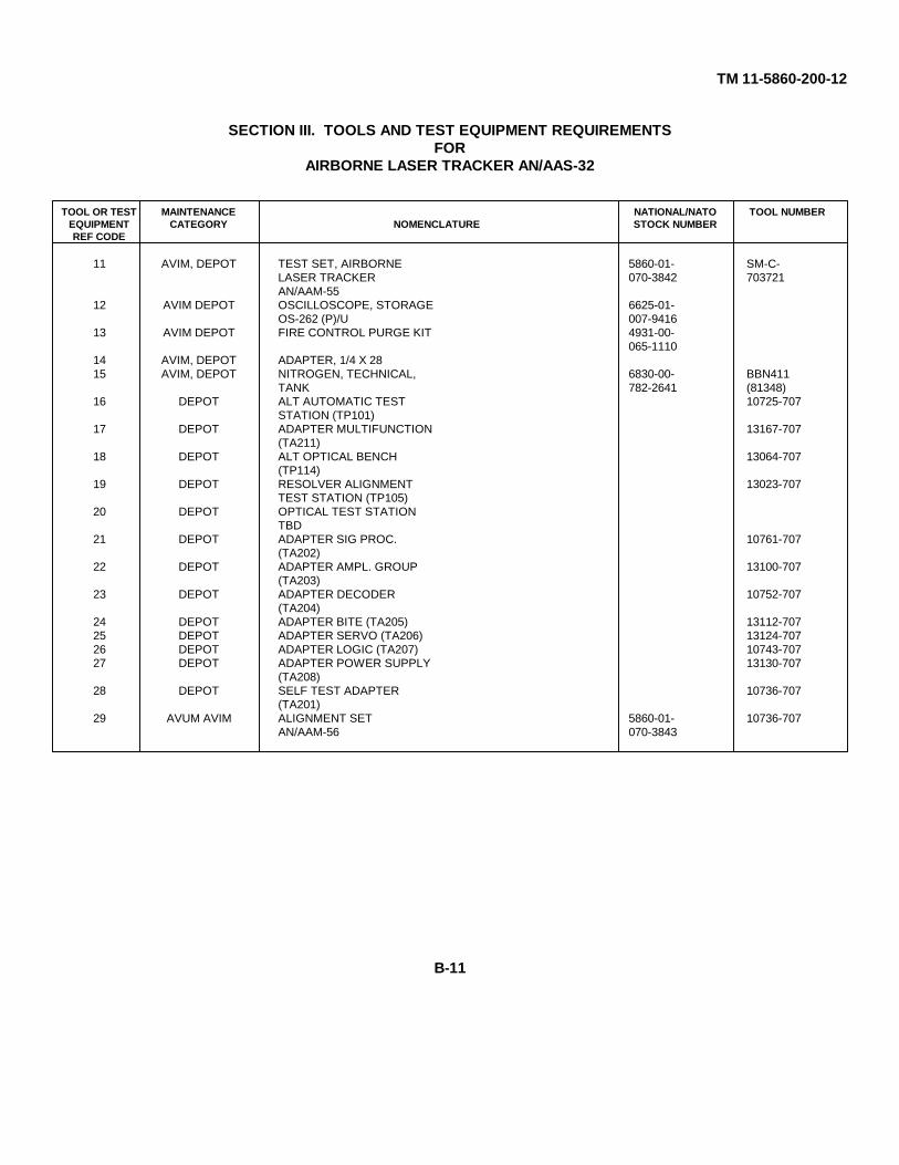
SECTION III. TOOLS AND TEST EQUIPMENT REQUIREMENTSFOR
AIRBORNE LASER TRACKER AN/AAS-32
TOOL OR TEST MAINTENANCE NATIONAL/NATO TOOL NUMBEREQUIPMENT CATEGORY NOMENCLATURE STOCK NUMBERREF CODE
1 AVUM TOOL KIT, ELECTRONIC 5180-00-EQUIPMENT TK-101/G OR 064-5178ARMAMENT TOOL KIT(BASIC AND SUPPLEMENT)
2 AVIM, DEPOT TOOL KIT, ELECTRONIC 5180-00-EQUIPMENT TK-105/G OR 610-8177ARMAMENT TOOL KIT(BASIC AND SUPPLEMENT)
3 AVIM, DEPOT TOOL KIT, ELECTRONIC 5180-00-EQUIPMENT TK-100/G OR 605-0079ARMAMENT TOOL KIT(BASIC AND SUPPLEMENT)
4 AVIM, DEPOT OSCILLOSCOPE 6625-00-AN/USM-281C 106-9622
5 AVIM, DEPOT DIGITAL VOLTMETER 6625-00-AN/GSM-64B 022-7894
6 AVIM, DEPOT METASCOPE AN/PAS-6 5855-00-790-6197
7 AVIM, DEPOT SIGNAL GENERATOR 6625-01-SG-117/ U 133-6160
8 AVIM, DEPOT COUNTER ELECTRONIC 6625-01-AN/USM-459 061-8928
9 AVIM, DEPOT POWER SUPPLY PP-3940/G 6130-00-(2 EACH) 953-7500
10 AVIM, DEPOT MULTIMETER ME-26B/U 6625-00-646-9409
B-10
TM 11-5860-200-12
SECTION III. TOOLS AND TEST EQUIPMENT REQUIREMENTSFOR
AIRBORNE LASER TRACKER AN/AAS-32
TOOL OR TEST MAINTENANCE NATIONAL/NATO TOOL NUMBEREQUIPMENT CATEGORY NOMENCLATURE STOCK NUMBERREF CODE
11 AVIM, DEPOT TEST SET, AIRBORNE 5860-01- SM-C-LASER TRACKER 070-3842 703721AN/AAM-55
12 AVIM DEPOT OSCILLOSCOPE, STORAGE 6625-01-OS-262 (P)/U 007-9416
13 AVIM DEPOT FIRE CONTROL PURGE KIT 4931-00-065-1110
14 AVIM, DEPOT ADAPTER, 1/4 X 2815 AVIM, DEPOT NITROGEN, TECHNICAL, 6830-00- BBN411
TANK 782-2641 (81348)16 DEPOT ALT AUTOMATIC TEST 10725-707
STATION (TP101)17 DEPOT ADAPTER MULTIFUNCTION 13167-707
(TA211)18 DEPOT ALT OPTICAL BENCH 13064-707
(TP114)19 DEPOT RESOLVER ALIGNMENT 13023-707
TEST STATION (TP105)20 DEPOT OPTICAL TEST STATION
TBD21 DEPOT ADAPTER SIG PROC. 10761-707
(TA202)22 DEPOT ADAPTER AMPL. GROUP 13100-707
(TA203)23 DEPOT ADAPTER DECODER 10752-707
(TA204)24 DEPOT ADAPTER BITE (TA205) 13112-70725 DEPOT ADAPTER SERVO (TA206) 13124-70726 DEPOT ADAPTER LOGIC (TA207) 10743-70727 DEPOT ADAPTER POWER SUPPLY 13130-707
(TA208)28 DEPOT SELF TEST ADAPTER 10736-707
(TA201)29 AVUM AVIM ALIGNMENT SET 5860-01- 10736-707
AN/AAM-56 070-3843
B-11

TM 11-5860-200-12
SECTION IV. REMARKS
REFERENCECODE
REMARKS
A Test using Built-in-Test Equipment (BITE).
B Clean receiver dome.
C Boresight ALT to aircraft.
D Repair by replacing foam, pressure relief valve, latches or handle.
E By replacement of lamps, knobs, etc.
F Repair of the platform assembly is accomplished while installed in the receiver tracker. Repair by R/Rthe Dome Assy, Az or El Gyro, Optics Assy, Signal Processor, or Desiccant. Purge before installing.
G Not used.
H By replacing attaching hardware.
I Repair optics by R/R Lens, Detector or Pre-Amp Assembly.
J By replacement of front panel switch.
K Repair by R/R faulty modules.
L Ensure ALT will Track/Slew/Align the TSU.
B-12

TM 11-5860-200-12
APPENDIX C
COMPONENTS OF END ITEM AND BASIC ISSUE ITEMS LIST
Section I. INTRODUCTION
C-1. SCOPE
This appendix lists components of end item and basic issue items for the ALT to help you inventory items required forsafe and efficient operation.
C-2. GENERAL
The Components of End Item List is divided into the following sections:
a. Section II. Components of End Item. This listing is for informational purposes only, and is not authority torequisition replacements. These items are part of the end item, but are removed and separately packaged fortransportation or shipment. As part of the end item, these items must be with the end item whenever it is issued ortransferred between property accounts. Illustrations are furnished to assist you in identifying the items.
b. Section III. Basic Issue Items (BII). These are the minimum essential items required to place the ALT inoperation, to operate it, and to perform emergency repairs. Although shipped separately packaged, BII must be with theALT during operation and whenever it is transferred between property accounts. The illustrations will assist you withhard-to-identify items. This manual is your authority to request/requisition replacement BII, based on TOE/MTOEauthorization of the end item.
C-3. EXPLANATION OF COLUMNS
The following provides an explanation of columns found in the tabular listing:
a. Column (1) - Illustration Number (Illus No.). This column indicates the number of the illustration in which theitem is shown.
C-1

TM 11-5860-200-12
b. Column (2) - National Stock Number. Indicates the National stock number assigned to the item and will be usedfor requisitioning purposes.
c. Column (3) - Description. Indicates the Federal item name and, if required, a minimum description to identifyand locate the item. The last line for each item indicates the FSCM (in parentheses) followed by the part number.
d. Column (4) - Unit of Measure (U/M) Indicates the used in performing the actual operational/maintenancefunction. This measure is expressed by a two-character alphabetical abbreviation (e.g., ea, in, pr).
e. Column (5) - Quantity Required (Qty rqr). Indicates the quantity of the item authorized to be used with/on theequipment.
C-2

TM 11-5860-200-12
SECTION II. COMPONENTS OF END ITEM
(1) (2) (3) (4) (5)National
Illus. Stock Description QtyNo. Number FCSM And Part Number U/M rqr
1-1 5860-01-072-1017 RECEIVER-TRACKER, LASER EA 1R-1920/AAS-32 FSCM:54490,P/N SM-D-703678
1-1 5860-01-071-5152 ELECTRONIC COMPONENTS EA 1ASSEMBLY MX-9623/AAS-32FSCM :54490,P/N SM-D-703697
1-1 5860-01-071-5061 CONTROL, LASER TRACKER EA 1C-9641/AAS-32 FSCM:54490,P/N SM-D-703726
C-3
TM 11-5860-200-12
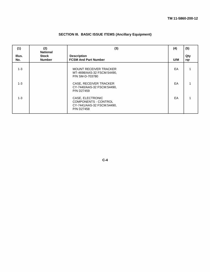
SECTION III. BASIC ISSUE ITEMS (Ancillary Equipment)
(1) (2) (3) (4) (5)National
Illus. Stock Description QtyNo. Number FCSM And Part Number U/M rqr
1-3 MOUNT RECEIVER TRACKER EA 1MT-4698/AAS-32 FSCM:54490,P/N SM-D-703780
1-3 CASE, RECEIVER TRACKER EA 1CY-7440/AAS-32 FSCM:54490,P/N D27459
1-3 CASE, ELECTRONIC EA 1COMPONENTS - CONTROLCY-7441/AAS-32 FSCM:54490,P/N D27458
C-4
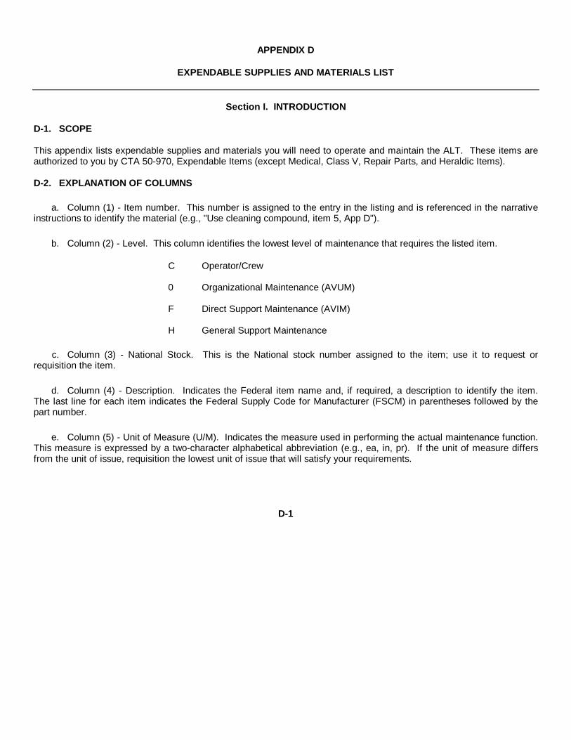
APPENDIX D
EXPENDABLE SUPPLIES AND MATERIALS LIST
Section I. INTRODUCTION
D-1. SCOPE
This appendix lists expendable supplies and materials you will need to operate and maintain the ALT. These items areauthorized to you by CTA 50-970, Expendable Items (except Medical, Class V, Repair Parts, and Heraldic Items).
D-2. EXPLANATION OF COLUMNS
a. Column (1) - Item number. This number is assigned to the entry in the listing and is referenced in the narrativeinstructions to identify the material (e.g., "Use cleaning compound, item 5, App D").
b. Column (2) - Level. This column identifies the lowest level of maintenance that requires the listed item.
C Operator/Crew
0 Organizational Maintenance (AVUM)
F Direct Support Maintenance (AVIM)
H General Support Maintenance
c. Column (3) - National Stock. This is the National stock number assigned to the item; use it to request orrequisition the item.
d. Column (4) - Description. Indicates the Federal item name and, if required, a description to identify the item.The last line for each item indicates the Federal Supply Code for Manufacturer (FSCM) in parentheses followed by thepart number.
e. Column (5) - Unit of Measure (U/M). Indicates the measure used in performing the actual maintenance function.This measure is expressed by a two-character alphabetical abbreviation (e.g., ea, in, pr). If the unit of measure differsfrom the unit of issue, requisition the lowest unit of issue that will satisfy your requirements.
D-1

SECTION II. EXPENDABLE SUPPLIES AND MATERIALS LIST
(1) (2) (3) (4) (5)NATIONAL
ITEM STOCKNUMBER LEVEL NUMBER DESCRIPTION U/M
1 0 CLEANING COMPOUND 1MIL-C-43454A FSN TYPE II
2 0 PAINT, MIL-C-22750, COLOR 1NO. 37038 (FED-STD-595)
3 0 PRIMER, MIL-P-23377
4 0 7920-00-401-8034 LINT-FREE CLOTH
5 0 PAINT, MIL-14072, FINISH 1P513P
6 0 7930-00-395-9452 CLEANING COMPOUND
7 0 7920-00-178-8315 SOFT-BRISTLED BRUSH 1
8 0 PAINT, MILITARY 1SPECIFICATION TT-E-527,COLOR NO. X34087 PERFED-STD-595 (OLIVE DRAB)
9 0 PRIMER, ZINC CHROMATE, 1MILITARY SPECIFICATIONTT-P-1 157
10 0 0415-00-682-6786 PLASTIC GLOVES 1
D-2
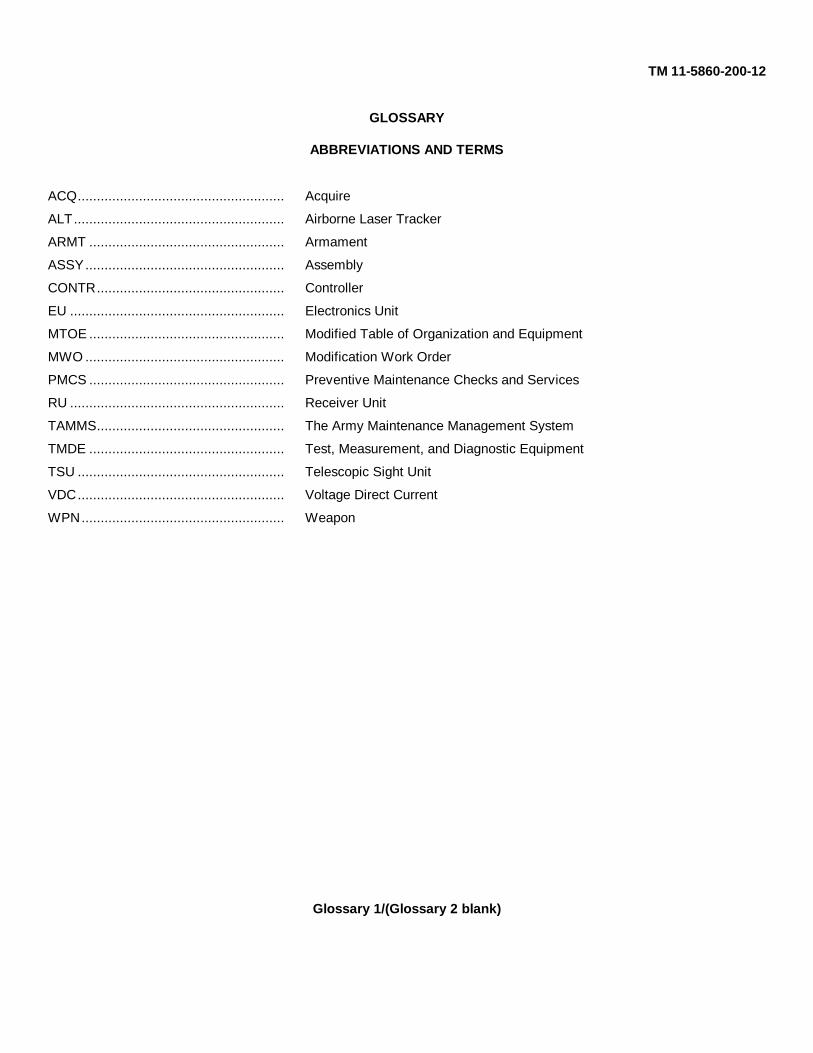
TM 11-5860-200-12
GLOSSARY
ABBREVIATIONS AND TERMS
ACQ...................................................... Acquire
ALT....................................................... Airborne Laser Tracker
ARMT ................................................... Armament
ASSY.................................................... Assembly
CONTR................................................. Controller
EU ........................................................ Electronics Unit
MTOE ................................................... Modified Table of Organization and Equipment
MWO .................................................... Modification Work Order
PMCS ................................................... Preventive Maintenance Checks and Services
RU ........................................................ Receiver Unit
TAMMS................................................. The Army Maintenance Management System
TMDE ................................................... Test, Measurement, and Diagnostic Equipment
TSU ...................................................... Telescopic Sight Unit
VDC...................................................... Voltage Direct Current
WPN..................................................... Weapon
Glossary 1/(Glossary 2 blank)

By Order of the Secretary of the Army:
JOHN A. WICKHAM JR.General, United States Army
Official: Chief of Staff
ROBERT M. JOYCEMajor General, United States Army
The Adjutant General
Distribution:
To be distributed in accordance with special list.
U. S. GOVERNMENT PRINTING OFFICE : 1994 0 - 300-421 (01235)
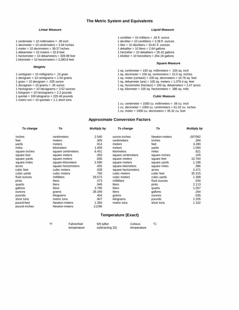
The Metric System and Equivalents
Linear Measure Liquid Measure
1 centiliter = 10 milliters = .34 fl. ounce1 centimeter = 10 millimeters = .39 inch 1 deciliter = 10 centiliters = 3.38 fl. ounces1 decimeter = 10 centimeters = 3.94 inches 1 liter = 10 deciliters = 33.81 fl. ounces1 meter = 10 decimeters = 39.37 inches 1 dekaliter = 10 liters = 2.64 gallons1 dekameter = 10 meters = 32.8 feet 1 hectoliter = 10 dekaliters = 26.42 gallons1 hectometer = 10 dekameters = 328.08 feet 1 kiloliter = 10 hectoliters = 264.18 gallons1 kilometer = 10 hectometers = 3,280.8 feet
Square MeasureWeights
1 sq. centimeter = 100 sq. millimeters = .155 sq. inch1 centigram = 10 milligrams = .15 grain 1 sq. decimeter = 100 sq. centimeters = 15.5 sq. inches1 decigram = 10 centigrams = 1.54 grains 1 sq. meter (centare) = 100 sq. decimeters = 10.76 sq. feet1 gram = 10 decigram = .035 ounce 1 sq. dekameter (are) = 100 sq. meters = 1,076.4 sq. feet1 decagram = 10 grams = .35 ounce 1 sq. hectometer (hectare) = 100 sq. dekameters = 2.47 acres1 hectogram = 10 decagrams = 3.52 ounces 1 sq. kilometer = 100 sq. hectometers = .386 sq. mile1 kilogram = 10 hectograms = 2.2 pounds1 quintal = 100 kilograms = 220.46 pounds Cubic Measure1 metric ton = 10 quintals = 1.1 short tons
1 cu. centimeter = 1000 cu. millimeters = .06 cu. inch1 cu. decimeter = 1000 cu. centimeters = 61.02 cu. inches1 cu. meter = 1000 cu. decimeters = 35.31 cu. feet
Approximate Conversion Factors
To change To Multiply by To change To Multiply by
inches centimeters 2.540 ounce-inches Newton-meters .007062feet meters .305 centimeters inches .394yards meters .914 meters feet 3.280miles kilometers 1.609 meters yards 1.094square inches square centimeters 6.451 kilometers miles .621square feet square meters .093 square centimeters square inches .155square yards square meters .836 square meters square feet 10.764square miles square kilometers 2.590 square meters square yards 1.196acres square hectometers .405 square kilometers square miles .386cubic feet cubic meters .028 square hectometers acres 2.471cubic yards cubic meters .765 cubic meters cubic feet 35.315fluid ounces milliliters 29,573 cubic meters cubic yards 1.308pints liters .473 milliliters fluid ounces .034quarts liters .946 liters pints 2.113gallons liters 3.785 liters quarts 1.057ounces grams 28.349 liters gallons .264pounds kilograms .454 grams ounces .035short tons metric tons .907 kilograms pounds 2.205pound-feet Newton-meters 1.356 metric tons short tons 1.102pound-inches Newton-meters .11296
Temperature (Exact)
°F Fahrenheit 5/9 (after Celsius °Ctemperature subtracting 32) temperature

PIN: 055070-000

This fine document...
Was brought to you by me:
Liberated Manuals -- free army and government manuals
Why do I do it? I am tired of sleazy CD-ROM sellers, who take publicly available information, slap “watermarks” and other junk on it, and sell it. Those masters of search engine manipulation make sure that their sites that sell free information, come up first in search engines. They did not create it... They did not even scan it... Why should they get your money? Why are not letting you give those free manuals to your friends?
I am setting this document FREE. This document was made by the US Government and is NOT protected by Copyright. Feel free to share, republish, sell and so on.
I am not asking you for donations, fees or handouts. If you can, please provide a link to liberatedmanuals.com, so that free manuals come up first in search engines:
<A HREF=http://www.liberatedmanuals.com/>Free Military and Government Manuals</A>
– SincerelyIgor Chudovhttp://igor.chudov.com/
– Chicago Machinery Movers


![TM DPP - 1 - Motion...DPP - 4 JEE [MAIN + ADV.] DIVISION TM SINGLE CORRECT QUESTIONS 1. A certain dye absorbs light of certain wavelength and then fluorescence light of wavelength](https://static.fdocuments.net/doc/165x107/60b53369c965c11bee79c4fb/tm-dpp-1-motion-dpp-4-jee-main-adv-division-tm-single-correct-questions.jpg)


