TITAN EXPLORER ENTRY, DESCENT AND LANDING TRAJECTORY DESIGN · TITAN EXPLORER ENTRY, DESCENT AND...
15
AAS 06-077 TITAN EXPLORER ENTRY, DESCENT AND LANDING TRAJECTORY DESIGN Jody L. Fisher and Robert E. Lindberg National Institute of Aerospace and Mary Kae Lockwood Johns Hopkins Applied Physics Laboratory 29th ANNUAL AAS GUIDANCE AND CONTROL CONFERENCE February 4-8, 2006 Sponsored by Breckenridge, Colorado Rocky Mountain Section AAS Publications Office, P.O. Box 28130 - San Diego, California 92198 https://ntrs.nasa.gov/search.jsp?R=20080013601 2018-07-22T05:21:45+00:00Z
Transcript of TITAN EXPLORER ENTRY, DESCENT AND LANDING TRAJECTORY DESIGN · TITAN EXPLORER ENTRY, DESCENT AND...

AAS 06-077
TITAN EXPLORER ENTRY, DESCENT AND
LANDING TRAJECTORY DESIGN
Jody L. Fisher and Robert E. Lindberg
National Institute of Aerospace and
Mary Kae Lockwood Johns Hopkins Applied Physics Laboratory
29th ANNUAL AAS GUIDANCE AND CONTROL CONFERENCE
February 4-8, 2006 Sponsored by
Breckenridge, Colorado Rocky Mountain Section
AAS Publications Office, P.O. Box 28130 - San Diego, California 92198
https://ntrs.nasa.gov/search.jsp?R=20080013601 2018-07-22T05:21:45+00:00Z

1
AAS 06-077
TITAN EXPLORER ENTRY, DESCENT AND LANDING
TRAJECTORY DESIGN
Jody L. Fisher*
Robert E. Lindberg†
Mary Kae Lockwood‡
The Titan Explorer mission concept includes an orbiter, entry probe and
inflatable airship designed to take remote and in-situ measurements of Titan’s
atmosphere. A modified entry, descent and landing trajectory at Titan that
incorporates mid-air airship inflation (under a parachute) and separation is
developed and examined for Titan Explorer. The feasibility of mid-air inflation
and deployment of an airship under a parachute is determined by implementing
and validating an airship buoyancy and inflation model in the trajectory
simulation program, Program to Optimize Simulated Trajectories II (POST2). A
nominal POST2 trajectory simulation case study is generated which examines
different descent scenarios by varying airship inflation duration, orientation, and
separation. The buoyancy model incorporation into POST2 is new to the
software and may be used in future trajectory simulations. Each case from the
nominal POST2 trajectory case study simulates a successful separation between
the parachute and airship systems with sufficient velocity change as to alter their
paths to avoid collision throughout their descent. The airship and heatshield
also separate acceptably with a minimum distance of separation from the
parachute system of 1.5 km. This analysis shows the feasibility of airship
inflation on a parachute for different orientations, airship separation at various
inflation times, and preparation for level-flight at Titan.
INTRODUCTION
The National Aeronautics and Space Administration’s (NASA) scientific and exploration efforts strive to
accomplish two strategic goals: 1) to explore the fundamental principles of physics, chemistry, and biology
through research in the unique natural laboratory of space, and 2) to explore the solar system and the
universe beyond, understand the origin and evolution of life, and search for evidence of life elsewhere.1 To
help achieve the latter of these goals, many mission concepts are on the drawing board to provide a more
affordable way of delivering spacecraft and scientific instruments to their planetary destinations. One of
these mission concepts is Titan Explorer. Titan, the largest moon of Saturn, is currently the only known
moon in the solar system to have an atmosphere. Additionally, the condition of Titan’s atmosphere (rich in
nitrogen and hydrocarbons, similar to Earth in its pre-biotic state) may give clues about the origin of life on
Earth. Due to the expensive (billions of US dollars) and lengthy flight (6-11 years) it takes to reach the
* Research Engineer, National Institute of Aerospace, 100 Exploration Way, Hampton, VA 23666.
E-mail: [email protected]. Phone: (757) 864-4508, FAX: (757)864-8675. † President and Executive Director, National Institute of Aerospace; also Research Professor, Mechanical and Aerospace Engineering
Dept., University of Virginia. E-mail: [email protected]. Phone: (757) 325-6750, FAX: (757)325-6754. ‡ Systems Engineer, Space Department, Johns Hopkins University Applied Physics Laboratory, 11100 Johns Hopkins Rd, Laurel,
MD 20723. E-mail: [email protected]. Phone: (443)778-2193, FAX: (443)778-6635.
2
Saturnian system,2 cost and time saving technologies such as propellant-saving maneuvers and
atmospheric-entry techniques, must be developed and utilized to enable a feasible mission to Titan.
Entry, descent and landing (EDL) is a mission sequence consisting of three main stages that involve a vehicle
entering an atmosphere, descending through the atmosphere with the aid of one or many parachutes or other
decelerators, and either landing on the surface of the planet or transitioning into other atmospheric flight
operations. Through the use of an atmosphere via aerodynamic forces to modify a trajectory, this direct entry
technique is important for enabling exploration and scientific in-situ measurement of planetary atmospheres
and surfaces. Various EDL methods have been successfully utilized in many NASA missions to date. In
addition, the European Space Agency (ESA) Huygens probe (the first probe to enter Titan’s atmosphere and
impact its surface) used EDL techniques such as ballistic entry with a three-stage parachute descent system, to
successfully take in-situ and scientific measurements at Titan. However, NASA’s Titan Explorer3,4
mission
concept incorporates airship flight for additional scientific measurements and it may also give insight into a
more globalized perspective of Titan’s atmosphere and surface characteristics. The buoyancy, inflation and
transition of the airship, in addition to the entry and descent, must be modeled to analyze the feasibility of
mid-air airship inflation (under a parachute) and deployment.
TRAJECTORY DESIGN AND SIMULATION
The Titan Explorer EDL trajectory development begins with the 3-degree-of-freedom (3DOF) entry trajectory
simulation in Program to Optimize Simulated Trajectories II (POST2).5,6,7
POST2 is a generalized point
mass, discrete parameter targeting and optimization trajectory program. POST2 has the ability to simulate
3DOF, 6DOF and multi-DOF trajectories for multiple vehicles in various flight regimes (i.e. entry, launch,
rendezvous, and intercept trajectories). POST2 also has the capability to include different atmosphere,
aerodynamics, gravity, propulsion, parachute and navigation system models. Many of these models have
been used to simulate the entry trajectories for previous NASA missions, i.e. Mars Exploration Rovers
(MER), Genesis, Stardust, Mars Path Finder (MPF), as well as current and planned NASA missions such as
Mars Phoenix Lander, and Mars Science Laboratory.
The Titan Explorer EDL simulation includes vehicle geometric parameters, an aerodynamic database, Titan’s
gravity and atmosphere models, and initial states. Titan Global Reference Atmospheric Model (Titan-
GRAM), parachute inflation and drag models are also included in the simulation. Table 1 shows the main
sequential events in the POST2 simulation with commentary. It should be noted that the simulation event
numbers are widely spaced to account for the possibility of future event additions to the simulation.
Table 1
TITAN EXPLORER NOMINAL POST2 SIMULATION EVENTS
Event Event Description Comment
1 Simulation initialization Input vehicle geometry, mass, initial
conditions, and gravity model
100 Entry interface and aerodynamic activation Activate atmosphere model
200 Parachute activation Start parachute timers
220 Parachute deployment
240 Parachute inflation Parachute full inflation
300 Backshell-heatshield separation and airship inflation Initialize airship inflation
350 Parachute-backshell and airship-heatshield separation
350 Multiple vehicle tracking activation Simulate separated vehicles/systems
375 Heatshield deployment
400 Initial airship level-flight Fully-inflated airship reaches final altitude
450 Parachute-backshell surface touchdown
999 Final event Simulation cut-off after Event 450

3
Critical Design Requirements
The initial conditions for the Titan Explorer entry phase of the probe consist of a ballistic direct entry from
a hyperbolic approach with an inertial entry velocity and altitude of 6.5 km/s and 1000 km.8 The entry
altitude of 1000 km is a commonly assumed atmospheric interface altitude for Titan. The entry flight path
angle (EFPA) requirement of -50° with ±5° (3σ) dispersions from R. J. Haw8 lies within the determined
skip-out EFPA and Huygens reference trajectory nominal EFPA range of -43.5° and -64°. A minimum
duration of 20 minutes on the parachute was selected to give adequate margin for airship inflation and
airship preparation for separation. The heatshield is deployed only after airship separation from the
parachute. The entry aeroshell is assumed to have a diameter of 3.75 m and 70-degree sphere-cone
forebody geometry.3,4
Airship Inflation and Deployment Approach
We have made certain simplifying assumptions in developing a buoyancy and inflation model for the Titan
Explorer airship during its descent on the parachute. The mass flow rate of the airship lifting gas is
undetermined from a systems perspective and is assumed to be constant from the inflation tank to the gasbag,
making the growth of the inflation gas mass linear during inflation. A constant mass flow rate may be
achieved by keeping the gas pressure and temperature constant. A pressure regulator can be used to keep the
pressure constant, and it is assumed that the tank temperature can be held constant through radiative heating if
the mass flow rate is slow enough. Airship orientation on the heatshield is considered two different ways:
nose-forward attached to heatshield (airship length parallel to flow) or gondola attached to heatshield (airship
length perpendicular to flow). During inflation of the airship, the nose-attached orientation is a more
streamlined approach. The gondola-attached orientation may be more dynamically stable, but exhibit more
drag. Figure 1 shows the two possible orientations for the airship.
Figure 1. Airship Orientation (not to scale): a) Nose-Attached b) Gondola-Attached
Backshell
Parachute
z
Heatshield
Inflating Airship
y
Tail
Gondola
Inflation Tanks
Parachute
a) b)
z
Inflation Tanks
Heatshield
Inflating Airship
y
Backshell
Tail
Gondola
Parachute Bridal
Parachute Bridal

4
Parachute Descent System Design
The Titan Explorer parachute descent subsystem is chosen as a 20° conical ribbon parachute, a mortar, and
system support. The parachute is sized to meet two criteria: 1) a descent time between one to two hours
for airship inflation process, and 2) the ballistic coefficient of the heatshield-airship combination during
inflation is greater than 1.4 times that of the parachute-backshell combination.9 The latter criterion is a rule
of thumb used in industry to determine a feasible separation of two components during flight. Using these
criteria, we designed the parachute to a 5.75 m nominal diameter, corresponding to a nominal area of 25.95
m2 and drag area of 13.62 m
2. Additionally, to meet the descent time criterion between one to two hours,
we chose a deployment Mach number of 1.1. Higher deployment Mach numbers would extend the descent
time. Delaying parachute deployment until this Mach number is a conservative approach in that it further
delays the start of the descent phase such that descent begins much closer to the surface.
Airship Buoyancy and Inflation Model
The buoyancy and inflation model of the airship at Titan is developed to estimate buoyancy, inflation rates,
airship growth during inflation, and ballistic coefficients. The model is implemented into POST2 and
integrated with the equations of motion to calculate the nominal trajectory needed to simulate and analyze the
trajectory of the airship during inflation while attached to the parachute, and the airship separation from the
parachute and heatshield.
The buoyancy and inflation model utilizes the Archimedes principle of buoyancy, linear inflation rates, and
atmospheric, entry probe and parachute conditions (i.e. density, pressure, temperature, altitude, and velocity).
Buoyancy is determined from the volume of the airship gasbag and the density of the helium lifting gas.10,11,12
The buoyant lift of the airship12
(La) at Titan is calculated from the buoyant mass (B) or total displaced mass
of the gasbag, the surface gravitational force at Titan (gtitan), the volume of the gasbag (Vgb), and the difference
between the atmospheric density (ρatm) and the density of helium (ρHe) using the equation
La = B gtitan = Vgb (ρatm - ρHe) gtitan (1)
Vgb is determined by the lifting gas mass and density at a buoyant altitude (airship operational altitude) of 5
km above the Titan surface. The gasbag half-length and maximum radius are assumed to be 8.42 m and 1.68
m, respectively.3 From those values and the lifting gas mass, inflation is modeled such that the lifting gas
mass flow rate was held constant and the growth of the gasbag radius is assumed to be linear with respect to
time. Two different inflation durations were tested: 20 minutes and 10 minutes. Figure 2 shows the linear
growth of airship buoyant lift with respect to inflation percentage generated in POST2.
Figure 2. POST2 Airship Buoyant Lift during Inflation

5
After full airship inflation, La remains constant at 667.4 N with a Vgb of 144.5 m3. These full inflation
conditions were selected to achieve a buoyant altitude (airship operational altitude) of 5 km. The completion
of airship inflation had been designed for an altitude range of 8 km to 6 km (close to, but above, the airship
operational altitude) to give a margin before heatshield deployment for airship orientation and system
configuration. Hence, the inflation-initialization altitude depends on the inflation duration and inflation-
completion altitude. The airship inflation-initialization altitudes were then chosen as 15 km for a 20 minute
inflation duration, and 11 km for a 10 minute inflation duration.
To determine the feasibility of airship inflation and separation with the parachute, two parameters are taken
into consideration: aerodynamic drag (D) and ballistic coefficient (BC). The difference in aerodynamic drag
of the parachute and the inflating airship-heatshield combination determines whether the tether between the
airship-heatshield and parachute is taut (i.e. whether there is tether tension).13
As the airship buoyancy
increases, the tension between the two systems decreases and the drag force transmitted to the parachute also
decreases, which leads to a less effective parachute. An effective design therefore seeks to achieve a drag
force of the parachute that must always be greater than the airship-heatshield combination drag force. Figure
3 illustrates the effects of airship buoyancy growth on the parachute during descent.
Figure 3. Schematic of Airship Buoyancy Effects during Descent (not to scale)
A mismatch or percentage difference in ballistic coefficient of the parachute-backshell combination and the
airship-heatshield combination is used to determine the feasibility of separation of the parachute-backshell and
airship-heatshield combination. The rule of thumb used for a feasible separation is: the ballistic coefficient of
the airship-heatshield combination must be greater than the nominal ballistic coefficient of the parachute-
backshell combination by 40%, including dispersions.9 Figure 4 illustrates the free-body diagram of the
airship-heatshield system used to determine the appropriate ballistic coefficient equation.
Lumped Inflating Airship-Heatshield
In Tension
Lumped Parachute-Backshell System
Loss of Tension
a) b)
Lumped Buoyant Airship-Heatshield

6
Figure 4. Airship-Heatshield Free-Body Diagram
To calculate the ballistic coefficient with the inclusion of buoyant mass for the airship-heatshield combination
(BChs), the buoyant mass (B) is subtracted from the airship-heatshield combination mass (mhs) to account for
buoyancy effects and the equation is multiplied by the dynamic pressure (q) to acquire the airship-heatshield
combination drag (Dhs) in the denominator. The ballistic coefficient of the parachute-backshell combination
(BCbs) is the mass of the system (mbs) divided by the drag coefficient of the parachute (CDp) multiplied by the
nominal parachute area (So). The calculation of the ballistic coefficient of each system (with the incorporation
of buoyancy and its components) are determined by
hs
hs
effDhs
hs
effDhs
hs
hsD
- Bmq
Aq C
- Bmq
AC
- BmBC
)()(============ (2)
and
oDp
bs
bsSC
mBC ==== . (3)
Using these BC values for each system, the ballistic coefficient mismatch is calculated by
−−−−====∆∆∆∆
hs
bshs
BC
BCBCBC . (4)
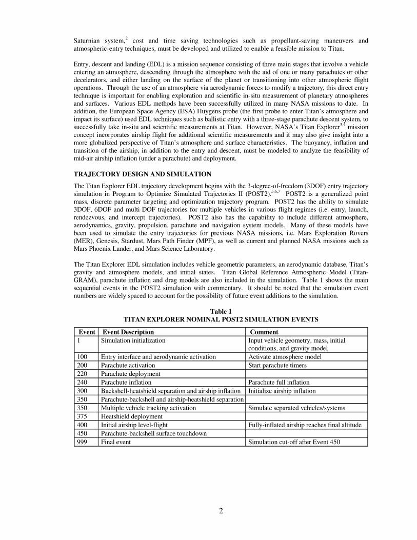
The effective area (Aeff) for the BChs is the cross-sectional area of the system perpendicular to the flow. The
determination of Aeff is based on either a gondola-attached or nose-attached orientation of the airship on the
heatshield. Aeff during inflation increases, for the gondola-attached orientation, and at approximately 62.5%
the cross-sectional area of the airship overtakes that of the heatshield. Figure 5 presents the change in Aeff with
inflation percentage for the gondola-attached orientation, which is the same for both inflation durations of 10
and 20 minutes.
v
L
La
D
mg
z
γγγγ
γγγγ
(90 − (90 − (90 − (90 − γ)γ)γ)γ)
Heatshield
Inflating Airship
γ γ γ γ ≈ -90 deg
y
7
Airship-Heatshield Effective Area for Gondola-Attached Orientation
0.000
5.000
10.000
15.000
20.000
25.000
30.000
0.00 10.00 20.00 30.00 40.00 50.00 60.00 70.00 80.00 90.00 100.00
% of Full Inflation
Eff
ec
tiv
e A
rea
(m
^2)
Airship reference area takes
over heatshield reference
area
Figure 5. Heatshield-Airship System Aeff for Gondola-Attached Orientation
For the nose-attached orientation of the airship, the heatshield cross-sectional area is always greater than the
airship, even at full inflation. Therefore, Aeff in that case is always equal to the reference area of the
heatshield, that is, it remains constant throughout the simulation.
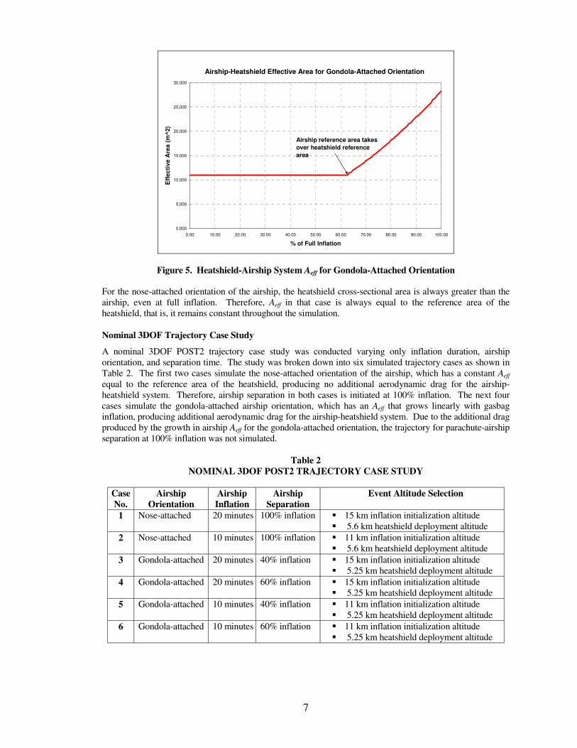
Nominal 3DOF Trajectory Case Study
A nominal 3DOF POST2 trajectory case study was conducted varying only inflation duration, airship
orientation, and separation time. The study was broken down into six simulated trajectory cases as shown in
Table 2. The first two cases simulate the nose-attached orientation of the airship, which has a constant Aeff
equal to the reference area of the heatshield, producing no additional aerodynamic drag for the airship-
heatshield system. Therefore, airship separation in both cases is initiated at 100% inflation. The next four
cases simulate the gondola-attached airship orientation, which has an Aeff that grows linearly with gasbag
inflation, producing additional aerodynamic drag for the airship-heatshield system. Due to the additional drag
produced by the growth in airship Aeff for the gondola-attached orientation, the trajectory for parachute-airship
separation at 100% inflation was not simulated.
Table 2
NOMINAL 3DOF POST2 TRAJECTORY CASE STUDY
Case
No.
Airship
Orientation
Airship
Inflation
Airship
Separation
Event Altitude Selection
1 Nose-attached 20 minutes 100% inflation � 15 km inflation initialization altitude
� 5.6 km heatshield deployment altitude
2 Nose-attached 10 minutes 100% inflation � 11 km inflation initialization altitude
� 5.6 km heatshield deployment altitude
3 Gondola-attached 20 minutes 40% inflation � 15 km inflation initialization altitude
� 5.25 km heatshield deployment altitude
4 Gondola-attached 20 minutes 60% inflation � 15 km inflation initialization altitude
� 5.25 km heatshield deployment altitude
5 Gondola-attached 10 minutes 40% inflation � 11 km inflation initialization altitude
� 5.25 km heatshield deployment altitude
6 Gondola-attached 10 minutes 60% inflation � 11 km inflation initialization altitude
� 5.25 km heatshield deployment altitude

8
TRAJECTORY SIMULATION RESULTS
Entry, Descent and Airship Transition Timeline
The entry, descent and airship transition timeline gives an overview of the results of the nominal 3DOF
POST2 simulation output. The sequence begins with probe entry interface, followed by parachute
deployment and descent. We assume airship inflation initiation at the time of backshell and heatshield
separation, and descent of the airship-heatshield on the parachute bridle. The airship is then cut away from
the parachute-backshell system at some point in inflation (i.e. 40%, 60%, or 100%) and the heatshield is
released from the fully-inflated airship before it reaches a 5 km altitude. The completion of the entry,
descent and airship transition establishes the initial conditions for mission operations of the airship at its
operational altitude. Figure 6 illustrates the nominal Titan Explorer entry, descent and airship transition
timeline generated from the nominal 3DOF POST2 simulation output. The range of values for time height,
and velocity at each event in the timeline, starting at airship inflation initialization, covers each of the six
cases of the nominal descent trajectory case study.
Figure 6. Titan Explorer Nominal EDL Timeline
Airship/Parachute Inflation and Separation Feasibility
The difference in aerodynamic drag of the parachute-backshell and airship-heatshield combination was
calculated to determine the maximum point at which the parachute and airship system could be separated.
The aerodynamic drag of the parachute was taken from the nominal POST2 3DOF simulation, tabulated, and
compared to the drag of the airship taken from the inflation and buoyancy model for both gondola-attached
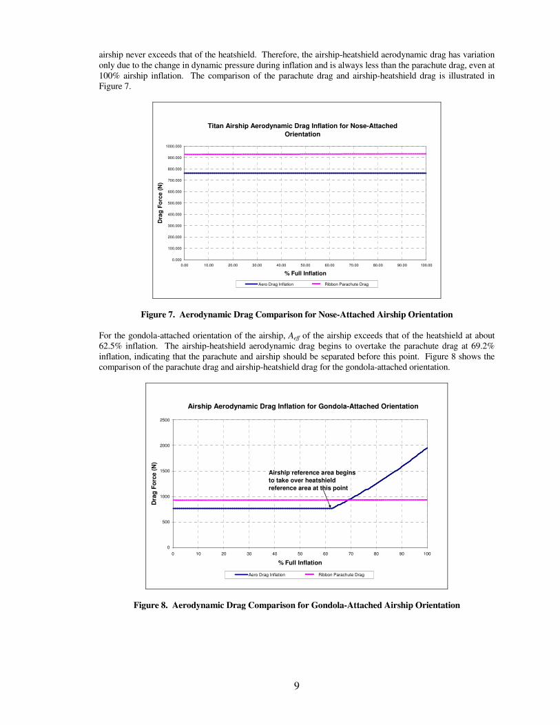
and nose-attached orientations. For the nose-attached orientation of the airship, the reference area, Aeff, of the
9
airship never exceeds that of the heatshield. Therefore, the airship-heatshield aerodynamic drag has variation
only due to the change in dynamic pressure during inflation and is always less than the parachute drag, even at
100% airship inflation. The comparison of the parachute drag and airship-heatshield drag is illustrated in
Figure 7.
Titan Airship Aerodynamic Drag Inflation for Nose-Attached
Orientation
0.000
100.000
200.000
300.000
400.000
500.000
600.000
700.000
800.000
900.000
1000.000
0.00 10.00 20.00 30.00 40.00 50.00 60.00 70.00 80.00 90.00 100.00
% Full Inflation
Dra
g F
orc
e (
N)
Aero Drag Inflation Ribbon Parachute Drag
Figure 7. Aerodynamic Drag Comparison for Nose-Attached Airship Orientation
For the gondola-attached orientation of the airship, Aeff of the airship exceeds that of the heatshield at about
62.5% inflation. The airship-heatshield aerodynamic drag begins to overtake the parachute drag at 69.2%
inflation, indicating that the parachute and airship should be separated before this point. Figure 8 shows the
comparison of the parachute drag and airship-heatshield drag for the gondola-attached orientation.
Airship Aerodynamic Drag Inflation for Gondola-Attached Orientation
0
500
1000
1500
2000
2500
0 10 20 30 40 50 60 70 80 90 100
% Full Inflation
Dra
g F
orc
e (
N)
Aero Drag Inflation Ribbon Parachute Drag
Airship reference area begins
to take over heatshield
reference area at this point
Figure 8. Aerodynamic Drag Comparison for Gondola-Attached Airship Orientation

10
The airship and parachute separation feasibility was determined by the difference in BC of the parachute-
backshell and airship-heatshield systems. For the gondola-attached airship orientation, a BC mismatch of
88.7% for separation at 40% inflation was calculated, which is substantially above the recommended 40%
mismatch for a heatshield separation from an entry body while on the parachute. Also, for separation at 60%
inflation the BC mismatch was 87.0%, which is well above the recommended mismatch. For the nose-
attached airship orientation, the BC mismatch for separation at 40% and 60% inflation is equal to that of the
gondola-attached orientation because Aeff does not exceeded the reference area of the heatshield at those
percentages for both orientations (see Figure 7 and Figure 8). A BC mismatch of 81.9%, for the nose-attached
orientation, was calculated for separation at 100% inflation. For the gondola-attached orientation, the
additional drag produced by the growth in Aeff (see Figure 8) for inflation above 60% leads to an ineffective
parachute as illustrated in Figure 3. For this reason, the BC mismatch for the gondola-orientation was not
calculated for separation at 100% inflation. Based on the inflation model, the BC mismatch calculation is
invariant for different inflation durations. Separation of the airship-heatshield from the parachute system for
either airship orientation is feasible at 40% and 60% inflation. Airship separation at 100% inflation is feasible
for the nose-attached orientation only. Significant additional margin is available by separating the airship-
heatshield from the parachute system prior to full airship inflation.
Nominal Trajectory Case Study Summary
The six nominal 3DOF trajectory cases were examined by plotting each descent altitude profile, and then
determining separation in altitude between the parachute and airship at heatshield deployment. All six cases
simulated successful airship inflation under the parachute, separation from the parachute, and heatshield
deployment. Even though all cases were feasible in terms of airship inflation and separation, there was a most
and least desirable case. Desirability was based on the altitude of separation between the airship and
parachute at heatshield deployment and time available to maneuver the airship before the airship and
parachute reach a common altitude after heatshield deployment.
Case 2 (with a nose-attached airship orientation, 10 minute airship inflation duration, and airship separation at
100% inflation) was feasible and the least desirable. Figure 9 shows the descent of the airship during
inflation, separation from the parachute, and heatshield deployment. Backshell separation and airship
inflation occurs at the selected altitude of 11 km and velocity of 6.4 m/s. The simulation data predicts a
successful separation shown by the large increase in velocity of the airship-heatshield combination, which is
more massive with less drag, and large decrease in velocity of the parachute-backshell combination, which is
less massive with more drag. This change in velocity occurs almost instantaneously after separation. The
heatshield is deployed from the airship and descends to the surface, while the airship descends to its buoyant
altitude of 5 km.

11
Figure 9. Case 2 3DOF POST2 Descent Trajectory
Figure 10 is the altitude profile for Case 2. It shows the gradual descent of the parachute-backshell,
deployment of the heatshield and initial level flight of the airship. The separation in altitude between the two
systems at heatshield deployment is 1.5 km and the time between heatshield deployment and airship-
parachute common altitude is 19 minutes.
Figure 10. Case 2 3DOF POST2 Altitude Profile

12
Case 3 (with a gondola-attached airship orientation, 20 minute airship inflation duration, and airship
separation at 40% inflation) was feasible and the most desirable. Figure 11 shows the descent of the airship
during inflation, separation from the parachute, and heatshield deployment. The descent profile of Case 3 is
different than Case 2 in that the airship separates at 40% inflation and Aeff grows during inflation because of
the gondola-attached orientation of the airship. The first change in slope of the airship-heatshield descent
occurs when the effective area overtakes that of the heatshield reference area. The second change in slope
occurs when the airship is fully inflated and there is no more change in buoyant force reducing the
deceleration rate. There is also a large change in velocity at heatshield deployment because of the loss of the
drag of the inflated airship attached to the heatshield.
Figure 11. Case 3 3DOF POST2 Descent Trajectory
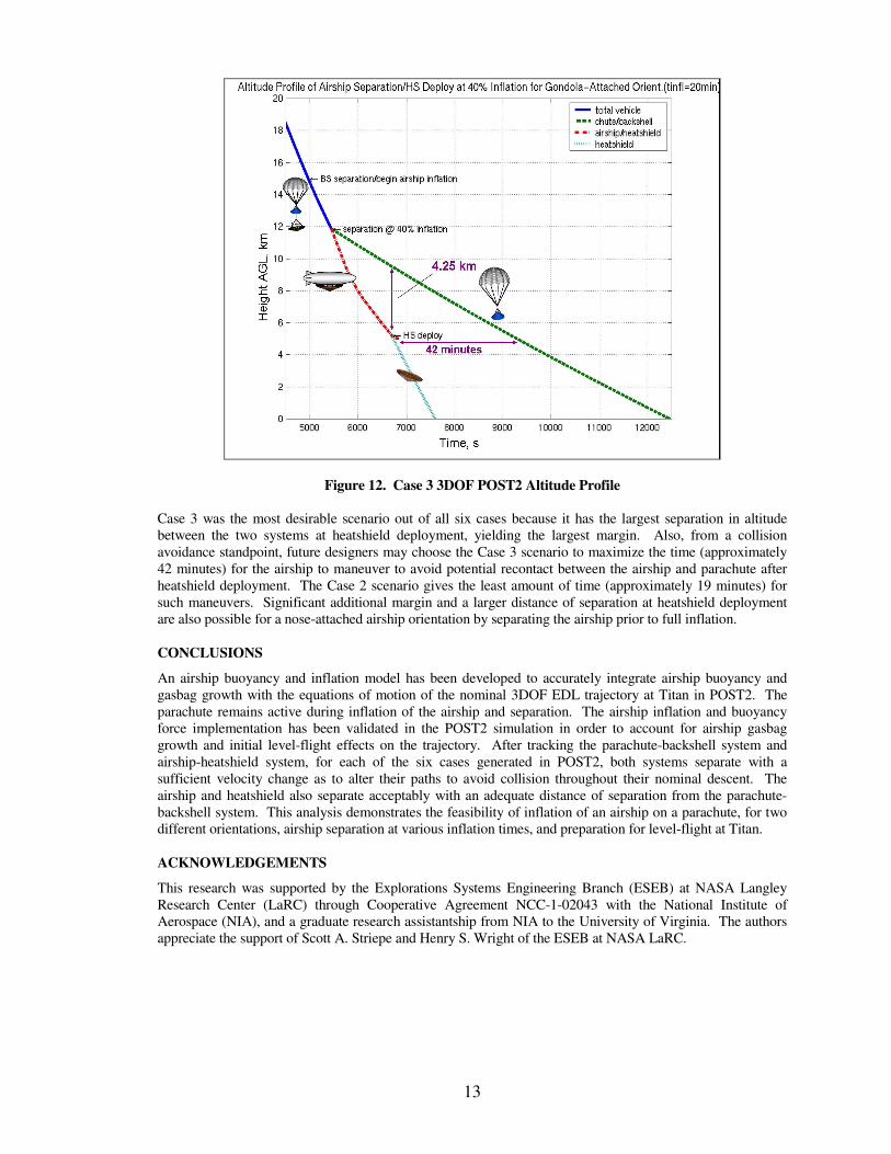
Figure 12 is the altitude profile for Case 3. The curve of the airship-heatshield changes slope which
corresponds to the growth of effective area and full airship inflation. This case yields a greater separation in
altitude of 4.25 km with time between heatshield deployment and airship-parachute common altitude of 42
minutes.
13
Figure 12. Case 3 3DOF POST2 Altitude Profile
Case 3 was the most desirable scenario out of all six cases because it has the largest separation in altitude
between the two systems at heatshield deployment, yielding the largest margin. Also, from a collision
avoidance standpoint, future designers may choose the Case 3 scenario to maximize the time (approximately
42 minutes) for the airship to maneuver to avoid potential recontact between the airship and parachute after
heatshield deployment. The Case 2 scenario gives the least amount of time (approximately 19 minutes) for
such maneuvers. Significant additional margin and a larger distance of separation at heatshield deployment
are also possible for a nose-attached airship orientation by separating the airship prior to full inflation.
CONCLUSIONS
An airship buoyancy and inflation model has been developed to accurately integrate airship buoyancy and
gasbag growth with the equations of motion of the nominal 3DOF EDL trajectory at Titan in POST2. The
parachute remains active during inflation of the airship and separation. The airship inflation and buoyancy
force implementation has been validated in the POST2 simulation in order to account for airship gasbag
growth and initial level-flight effects on the trajectory. After tracking the parachute-backshell system and
airship-heatshield system, for each of the six cases generated in POST2, both systems separate with a
sufficient velocity change as to alter their paths to avoid collision throughout their nominal descent. The
airship and heatshield also separate acceptably with an adequate distance of separation from the parachute-
backshell system. This analysis demonstrates the feasibility of inflation of an airship on a parachute, for two
different orientations, airship separation at various inflation times, and preparation for level-flight at Titan.
ACKNOWLEDGEMENTS
This research was supported by the Explorations Systems Engineering Branch (ESEB) at NASA Langley
Research Center (LaRC) through Cooperative Agreement NCC-1-02043 with the National Institute of
Aerospace (NIA), and a graduate research assistantship from NIA to the University of Virginia. The authors
appreciate the support of Scott A. Striepe and Henry S. Wright of the ESEB at NASA LaRC.

14
REFERENCES
1. NASA Office of Space Science, “Research Opportunities in Space Science-2003 (ROSS-2003),” NASA
Research Announcement, NRA 03-OSS-01, Washington, D.C, January, 2003.
2. Neugebauer, M., “The CRAF/Cassini Project,” AIAA Paper, AIAA 90-3852, Space Programs and
Technologies Conference, Huntsville, AL, Sept. 25-27, 1990.
3. Levine, J.S., Wright, H.S., et al, “Titan Explorer: The Next Step in the Exploration of a Mysterious
World,” NASA Vision Mission Study Final Report, NRA-03-OSS-01, NASA Langley Research Center,
2005.
4. Lockwood, M.K., “Titan Aerocapture Systems Analysis,” AIAA Paper, AIAA 2003-4799, 39th
AIAA/ASME/SAE/ASEE Joint Propulsion Conference and Exhibit, Huntsville, AL, July 20-23, 2003.
5. Bauer, G.L., Cornick, D.E., and Stevenson, R., “Capabilities and Applications of the Program to Optimize
Simulated Trajectories (POST),” NASA CR-2770, February 1977.
6. Striepe, S.A., et al, “Program to Optimize Simulated Trajectories (POSTII), Vol. II Utilization Manual,”
Version 1.1.6.G, January 2004, NASA Langley Research Center, Hampton, VA.
7. Striepe, S.A., Aguirre, J.T., Fisher, J.L., et al, “Program to Optimize Simulated Trajectories (POSTII), Vol.
I Guide for New Users,” Version 1.1.6.G, November 2003, NASA Langley Research Center, Hampton,
VA.
8. Haw, R.J., “Approach Navigation for a Titan Aerocapture Orbiter,” AIAA Paper, AIAA 2003-4802, 39th
AIAA/ASME/SAE/ASEE Joint Propulsion Conference and Exhibit, Huntsville, AL, July 20-23, 2003.
9. Raiszadeh, B., Private communication, NASA Langley Research Center, Hampton, VA, February 2005.
10. Colozza, A., “Evaluation of an Airship for Planetary Atmospheric Exploration,” AIAA Paper, AIAA
2004-6475, 2004.
11. Morrison, A.M., and Regan, F.J., “The Planar Dynamics of Airships,” AIAA Paper, AIAA 75-1395,
1975.
12. Dorrington, G.E., “Some General Remarks on the Design of Airships,” AIAA Paper, AIAA 99-3915,
1999.
13. Cameron, J.M., Kerzhanovich, V., and Quadrelli, M.B., “Multibody Dynamics of Parachute and
Balloon Flight Systems for Planetary Exploration,” Journal of Guidance, Control, and Dynamics, Vol.
27, No. 4, July-August 2004, pp. 564-571