Simulation Framework for Rapid Entry, Descent, and … · Simulation Framework for Rapid Entry,...
103
NASA Engineering and Safety Center Technical Assessment Report Document #: NESC-RP- 09-00530 Version: 1.0 Title: Simulation Framework for Rapid Entry, Descent, and Landing (EDL) Analysis Page #: 1 of 103 NESC Request No.: 09-00530 Simulation Framework for Rapid Entry, Descent, and Landing (EDL) Analysis December 17, 2009
Transcript of Simulation Framework for Rapid Entry, Descent, and … · Simulation Framework for Rapid Entry,...

NASA Engineering and Safety Center Technical Assessment Report
Document #:
NESC-RP-09-00530
Version:
1.0
Title:
Simulation Framework for Rapid Entry, Descent, and Landing (EDL) Analysis
Page #:
1 of 103
NESC Request No.: 09-00530
Simulation Framework for Rapid Entry, Descent, and Landing (EDL) Analysis
December 17, 2009

NASA Engineering and Safety Center Technical Assessment Report
Document #:
NESC-RP-09-00530
Version:
1.0
Title:
Simulation Framework for Rapid Entry, Descent, and Landing (EDL) Analysis
Page #:
2 of 103
NESC Request No.: 09-00530
Report Approval and Revision History
NOTE: This document was approved at the December 17, 2009, NRB. This document was submitted to the NESC Director on January 6, 2010, for configuration control.
Approved Version:
Original Signature Page on File 1/7/10
1.0 NESC Director Date
Version Description of Revision Office of Primary
Responsibility Effective Date
1.0 Initial Release Mr. Daniel G. Murri, NASA Technical Fellow, Flight Mechanics
12/17/09

NASA Engineering and Safety Center Technical Assessment Report
Document #:
NESC-RP-09-00530
Version:
1.0
Title:
Simulation Framework for Rapid Entry, Descent, and Landing (EDL) Analysis
Page #:
3 of 103
NESC Request No.: 09-00530
Table of Contents Volume I: Technical Assessment Report 1.0 Notification and Authorization ................................................................................................ 7
2.0 Signature Page ........................................................................................................................... 8
3.0 Team List ................................................................................................................................... 9
4.0 Executive Summary ................................................................................................................ 10
5.0 Models and Script Descriptions ............................................................................................. 11 5.1 Aerodynamic Models ................................................................................................................ 12
5.1.1 70-Degree Sphere-Cone (MER) Aerodynamic Database ............................................ 13 5.1.1.1 Mach Number/Entry Velocity...................................................................................... 13 5.1.1.2 Angle-of-Attack Range ................................................................................................ 13 5.1.1.3 Gas Chemistry .............................................................................................................. 14 5.1.1.4 Uncertainties/Dispersions ............................................................................................ 14 5.1.2 60-Degree Sphere-Cone (Genesis) Aerodynamic Database ........................................ 14 5.1.2.1 Mach Number/Entry Velocity...................................................................................... 15 5.1.2.2 Angle-of-Attack ........................................................................................................... 15 5.1.2.3 Gas Chemistry .............................................................................................................. 15 5.1.2.4 Dynamic Stability ........................................................................................................ 15 5.1.2.5 Uncertainties/Dispersions ............................................................................................ 16 5.1.3 45-Degree Sphere-Cone (Mars Microprobe) Aerodynamic Database ......................... 16 5.1.3.1 Mach Number/Entry Velocity...................................................................................... 16 5.1.3.2 Angle-of-Attack ........................................................................................................... 16 5.1.3.3 Dynamic Stability ........................................................................................................ 17 5.1.3.4 Gas Chemistry .............................................................................................................. 17 5.1.3.5 Uncertainties/Dispersions ............................................................................................ 17 5.1.4 Mid Lift/Drag Geometry (Ellipsled) Aerodynamic Database ...................................... 18 5.1.4.1 Data Parallel Line Relaxation ...................................................................................... 19 5.1.4.1 CART3D ...................................................................................................................... 19 5.1.4.2 Configuration-Based Aerodynamics ............................................................................ 20 5.1.4.3 Final Ellipsled Aerodynamic Database ........................................................................ 21 5.1.5 Hypersonic Inflatable Aerodynamic Decelerator (HIAD) Aerodynamic Database ..... 21 5.1.5.1 Leveraging the Constellation Program Crew Exploration Vehicle Database .............. 22 5.1.5.2 CART3D ...................................................................................................................... 23 5.1.5.3 Final Hypersonic Inflatable Aerodynamic Decelerator Aerodynamic Database ......... 23 5.1.6 Aerodynamic Models Inputs and Outputs in POST2................................................... 23
5.2 Guidance Algorithms ................................................................................................................ 30 5.2.1 Hybrid Predictor-Corrector Aerocapture Scheme Entry Guidance ............................. 31 5.2.2 Numerical Predictor-Corrector .................................................................................... 33 5.2.3 Theoretical Entry Guidance ......................................................................................... 38 5.2.3.1 Gravity Turn Terminal Descent Guidance ................................................................... 41

NASA Engineering and Safety Center Technical Assessment Report
Document #:
NESC-RP-09-00530
Version:
1.0
Title:
Simulation Framework for Rapid Entry, Descent, and Landing (EDL) Analysis
Page #:
4 of 103
NESC Request No.: 09-00530
5.2.3.2 Theoretical Background ............................................................................................... 41 5.2.3.3 Usage Guidelines ......................................................................................................... 43
5.3 Mass Models ............................................................................................................................. 45 5.3.1 Basic Operation Using EDLSA Mass Model .............................................................. 46 5.3.2 Mass Model Input Variable Ranges ............................................................................. 47 5.3.2.1 Ellipsled Mission Variable Bounds (MEDL_MTOGGLE ≤ 1) ................................... 48 5.3.2.2 MIAS Mission Variable Bounds (MEDL_MTOGGLE = 2) ....................................... 49 5.3.2.3 All Propulsive Mission Variable Bounds (MEDL_MTOGGLE = 3) .......................... 50 5.3.3 Mass Models POST2 Inputs/Outputs ........................................................................... 50
5.4 Vehicle Attitude Models for 3 DoF Simulation ........................................................................ 52 5.4.1 Pseudo-Controller for Bank Angle Modulation ........................................................... 52 5.4.2 Aerodynamic Trim in Angle-of-Attack and Sideslip Angle ........................................ 55
5.5 Environment Models ................................................................................................................. 57 5.5.1 Global Reference Atmosphere Models ........................................................................ 58 5.5.5.1 Mars-GRAM ................................................................................................................ 64 5.5.5.2 Titan-GRAM ................................................................................................................ 69 5.5.5.3 Venus-GRAM .............................................................................................................. 70 5.5.5.4 Neptune-GRAM ........................................................................................................... 72 5.5.5.5 Earth-GRAM ............................................................................................................... 73 5.5.5.6 Jupiter Table Atmosphere Model ................................................................................. 78 5.5.5.7 Uranus Atmosphere Model .......................................................................................... 79 5.5.5.8 Saturn Atmosphere Model ........................................................................................... 81 5.5.5.9 Gravity Models for POST2 .......................................................................................... 82
5.6 Scripts ..................................................................................................................................... 82 5.6.1 Function Scripts ........................................................................................................... 83 5.6.1.1 Animation Object Creation .......................................................................................... 83 5.6.1.2 File and Scientific Data Conversion ............................................................................ 83 5.6.1.3 Plotting and Plot Labels ............................................................................................... 83 5.6.1.4 POST2 Post-Processing ............................................................................................... 90 5.6.1.5 POST2 Data Management ........................................................................................... 91 5.6.1.6 Scientific Calculations ................................................................................................. 91 5.6.1.7 Cartesian Conversion Script ........................................................................................ 98 5.6.2 Tool Set Scripts ............................................................................................................ 98 5.6.2.1 POST2 Trajectory Animation Tool ............................................................................. 98 5.6.2.2 Monte Carlo PERL ...................................................................................................... 98 5.6.2.3 Single POST2 Run ....................................................................................................... 99 5.6.2.4 POST2 Test Suite ......................................................................................................... 99 5.6.2.5 POST2 Terrain Contour Plotting Tool ......................................................................... 99
6.0 Observation and NESC Recommendation ......................................................................... 100
7.0 Other Deliverables ................................................................................................................ 100
8.0 Definition of Terms ............................................................................................................... 101

NASA Engineering and Safety Center Technical Assessment Report
Document #:
NESC-RP-09-00530
Version:
1.0
Title:
Simulation Framework for Rapid Entry, Descent, and Landing (EDL) Analysis
Page #:
5 of 103
NESC Request No.: 09-00530
9.0 Acronyms List ....................................................................................................................... 102
List of Figures Figure 5.1.4.1. Mid L/D Geometry ........................................................................................................ 18 Figure 5.1.4.2. DPLR Solution .............................................................................................................. 19 Figure 5.1.4.3. CART3D Solution ......................................................................................................... 20 Figure 5.1.4.4. CBAERO Solution ........................................................................................................ 20 Figure 5.1.5.1. 23m HIAD ..................................................................................................................... 21 Figure 5.1.5.2. Anchored CBAERO Solution for HIAD ....................................................................... 22 Figure 5.1.5.3. Subsonic CART3D Solution for HIAD ......................................................................... 23 Figure 5.2.3.1. Gravity Turn Guidance Free-Body Diagram ................................................................. 41
List of Tables
Table 5.0.1. Responsible Individuals for Models Implemented and Report Sections ..................... 12 Table 5.1.3.1. Microprobe Aerodynamic Database Uncertainties Used in Flight Simulation ............ 18 Table 5.1.6.1. POST2 Inputs for the Aerodynamic Models in the Simulation Architecture for
Rapid EDL Systems Analysis Studies ......................................................................... 25 Table 5.1.6.2. POST2 Outputs from the Aerodynamic Models in the Simulation Architecture
for Rapid EDL Systems Analysis Studies ................................................................... 29 Table 5.2.1.1. POST2 Inputs for the HYPAS Guidance Algorithm ................................................... 32 Table 5.2.1.2. POST2 outputs for the HYPAS guidance algorithm ................................................... 32 Table 5.2.2.1. POST2 Inputs for the NPC Guidance Algorithm......................................................... 35 Table 5.2.2.2. POST2 Table Inputs for the NPC Guidance Algorithm .............................................. 37 Table 5.2.2.3. POST2 Outputs for the NPC Guidance Algorithm ...................................................... 37 Table 5.2.3.1. POST2 Inputs for the Theoretical Guidance Algorithm .............................................. 39 Table 5.2.3.2. POST2 Outputs for the Theoretical Guidance Algorithm ........................................... 40 Table 5.2.3.3. POST2 Inputs for the Gravity Turn Terminal Guidance Algorithm ............................ 44 Table 5.2.3.4. POST2 Outputs for the Gravity Turn Terminal Guidance Algorithm ......................... 45 Table 5.3.2.1. Ellipsled Descent Stage Inert Mass Response Surface Independent Variable Ranges 48 Table 5.3.2.2. MIAS Descent Stage Inert Mass Response Surface Independent Variable Ranges .... 49 Table 5.3.2.3. Propulsive Mission Descent Stage Inert Mass Response Surface Independent Variable
Ranges .......................................................................................................................... 50 Table 5.3.3.1. POST2 Inputs for the Mass Models ............................................................................. 51 Table 5.3.3.2. POST2 Outputs for the Mass Models .......................................................................... 51 Table 5.4.1.1. POST2 Inputs for the Bank Angle Pseudo-Controller Model ..................................... 54 Table 5.4.1.2. POST2 Outputs for the Bank Angle Pseudo-Controller Model ................................... 55 Table 5.4.2.1. POST2 Inputs for the Aerodynamic Trim Model ........................................................ 56 Table 5.4.2.2. POST2 Outputs for the Aerodynamic Trim Model ..................................................... 57 Table 5.5.1.1. POST2 Inputs to Invoke the GRAM Series ................................................................. 58 Table 5.5.1.2. POST2 Tables for the GRAM Series ........................................................................... 59 Table 5.5.1.3. POST2 Outputs for all GRAM Series .......................................................................... 59 Table 5.5.1.4. POST2 Inputs Common to Mars-GRAM, Titan-GRAM, Venus-GRAM, and Neptune-
GRAM ......................................................................................................................... 61

NASA Engineering and Safety Center Technical Assessment Report
Document #:
NESC-RP-09-00530
Version:
1.0
Title:
Simulation Framework for Rapid Entry, Descent, and Landing (EDL) Analysis
Page #:
6 of 103
NESC Request No.: 09-00530
Table 5.5.1.5. Additional POST2 Inputs for the Mars-GRAM Model ............................................... 64 Table 5.5.1.6. Additional POST2 Outputs for the Mars-GRAM Model ............................................. 68 Table 5.5.1.7. Additional POST2 Inputs for the Titan-GRAM Model ............................................... 69 Table 5.5.1.8. Additional POST2 Outputs for the Titan-GRAM Model ............................................ 70 Table 5.5.1.9. Additional POST2 Inputs for the Venus-GRAM Model ............................................. 71 Table 5.5.1.10. Additional POST2 Outputs for the Venus-GRAM Model ........................................... 71 Table 5.5.1.11. Additional POST2 Inputs for the Neptune-GRAM Model .......................................... 72 Table 5.5.1.12. Additional POST2 Outputs for the Neptune-GRAM Model ....................................... 73 Table 5.5.1.13. POST2 Inputs for the Earth-GRAM Model ................................................................. 73 Table 5.5.1.14. POST2 Outputs for the Earth-GRAM Model .............................................................. 77 Table 5.5.1.15. POST2 Inputs for the Jupiter Atmosphere Model ....................................................... 79 Table 5.5.1.16. Additional POST2 Outputs for the Jupiter atmosphere model .................................... 79 Table 5.5.1.17. POST2 Inputs for the Uranus Atmosphere Model ....................................................... 80 Table 5.5.1.18. Additional POST2 Outputs for the Uranus Atmosphere Model .................................. 80 Table 5.5.1.19. POST2 Inputs for the Saturn Atmosphere Model ........................................................ 81 Table 5.5.1.20. POST2 Outputs for the Saturn Atmosphere Model ..................................................... 81 Table 5.6.1.1. Animation Object Creation Scripts .............................................................................. 83 Table 5.6.1.2 File and Scientific Data Conversion Scripts ................................................................ 83 Table 5.6.1.3 Plotting and Plot Label Scripts .................................................................................... 84 Table 5.6.1.4. POST2 Post-Processing Scripts ................................................................................... 90 Table 5.6.1.5. POST2 Data Management Scripts ............................................................................... 91 Table 5.6.1.6. Scientific Calculation Scripts ....................................................................................... 92 Table 5.6.1.7. Cartesian conversion Script ......................................................................................... 98 Table 5.6.1.8. Monte Carlo PERL Script ............................................................................................ 99 Table 5.6.1.9. Single POST2 Run Script ............................................................................................ 99 Table 5.6.1.10. POST2 Test Suite Scripts ............................................................................................ 99 Table 5.6.1.11. POST2 Terrain Contour Plotting Script ..................................................................... 100
Volume II: Appendices (stand-alone volume) Appendix A. Gravity Turn Guidance Theoretical Development Appendix B. POST2 Mass Model Users’ Guide Appendix C. Animation Tool v2.3 Appendix D. Animation GUI v1.0 Appendix E. POST2 Scripts Users’ Guide

NASA Engineering and Safety Center Technical Assessment Report
Document #:
NESC-RP-09-00530
Version:
1.0
Title:
Simulation Architecture for Rapid Entry, Descent, and Landing Systems Analysis Studies
Page #:
7 of 103
NESC Request No.: 09-00530
Volume I: Technical Assessment Report
1.0 Notification and Authorization Mr. Daniel Murri, NASA Technical Fellow for Flight Mechanics, requested that the NASA Engineering and Safety Center (NESC) support a request from Mr. Harold Bell, Director Advanced Planning and Analysis Division, NASA Office of Chief Engineer to establish the Simulation Framework for Rapid Entry, Descent, and Landing (EDL) Analysis assessment within the NESC. The principal focus of the activity was to develop a simulation framework and a set of validated and documented sub-system models and scripts to allow rapid evaluation of EDL characteristics in systems analysis studies, preliminary design, mission development and execution, and time-critical assessments.
The Initial Evaluation for this assessment was presented and approved by the NESC Review Board (NRB) on March 12, 2009. Mr. Daniel Murri was selected to lead this assessment. The Assessment Plan was presented and approved by the NRB on March 26, 2009. The Phase 1 Stakeholder Outbrief was presented and approved by the NRB on November 5, 2009. The Phase 1 final report was presented and approved by the NRB on December 17, 2009.
The key stakeholders are Mr. Harold Bell, Mr. Thomas Zang, Lead, Entry, Descent, and Landing Systems Analysis (EDL-SA) team; and the NESC.

NASA Engineering and Safety Center Technical Assessment Report
Document #:
NESC-RP-09-00530
Version:
1.0
Title:
Simulation Framework for Rapid Entry, Descent, and Landing (EDL) Analysis
Page #:
8 of 103
NESC Request No.: 09-00530
2.0 Signature Page Submitted by: Mr. Daniel Murri Date Significant Contributors: Dr. Scott Striepe Date Mr. Richard Powell Date
Signatories declare the findings and observations complied in the report are factually based from data extracted from Program/Project documents, contractor reports, and open literature, and/or generated from independently conducted tests, analysis, and inspections.

NASA Engineering and Safety Center Technical Assessment Report
Document #:
NESC-RP-09-00530
Version:
1.0
Title:
Simulation Framework for Rapid Entry, Descent, and Landing (EDL) Analysis
Page #:
9 of 103
NESC Request No.: 09-00530
3.0 Team List
Name Discipline Organization Core Team Dan Murri NESC Team Lead LaRC Richard Powell Team Co-Lead LaRC/AMA Scott Striepe Simulation Lead LaRC Eric Queen Controls Lead LaRC Mark Schoenenberger Aerodynamics Lead LaRC Alicia Cianciolo Environments Lead LaRC John Wagner Mass Lead LaRC/NIA Loreyna Yeung Scripts Lead LaRC/ATK John Aguirre Software LaRC/Vigyan Carole Garrison Software LaRC/ATK Michael Kelly Principal Engineer (Back-up) NESC Dave Kinney Aerodynamics ARC Jack Mulqueen Aerospace Engineer MSFC Jill Prince Flight Mechanics LaRC David Way Flight Mechanics LaRC Carlos Westhelle Guidance JSC Consultants Phil Calhoun Controls GSFC Cornelius Dennehy NASA Technical Fellow, GN&C GSFC Michael Hagopian Senior AETD Engineer GSFC Kurt Kloesel Electrical Engineer DFRC Gary Mosier Aerospace Engineer GSFC Martin Steele Computer Engineer KSC Administrative Support Tricia Johnson MTSO Program Analyst LaRC Melinda Meredith Project Coordinator LaRC/ATK Linda Burgess Planning and Control Analyst LaRC/ATK Erin Moran Technical Writer LaRC/ATK

NASA Engineering and Safety Center Technical Assessment Report
Document #:
NESC-RP-09-00530
Version:
1.0
Title:
Simulation Framework for Rapid Entry, Descent, and Landing (EDL) Analysis
Page #:
10 of 103
NESC Request No.: 09-00530
4.0 Executive Summary The NASA Engineering and Safety Center (NESC) was requested to establish the Simulation Framework for Rapid Entry, Descent, and Landing (EDL) Analysis assessment, which involved development of an enhanced simulation architecture using the Program to Optimize Simulated Trajectories II (POST2) simulation tool. The assessment was requested to enhance the capability of the Agency to provide rapid evaluation of EDL characteristics in systems analysis studies, preliminary design, mission development and execution, and time-critical assessments. Many of the new simulation framework capabilities were developed to support the Agency EDL Systems Analysis (EDL-SA) team, that is conducting studies of the technologies and architectures that are required to enable higher mass robotic and human mission to Mars.
Many of the EDL-SA studies have been conducted using POST2, but with a variety of ad-hoc and undocumented sub-system models (e.g., mass, aerodynamics, atmosphere, guidance, control) and scripts. During the assessment, the NESC team developed a simulation framework and a set of validated and documented sub-system models (including mass models, a pseudo bank angle controller, aerodynamic trim, aerodynamic data models, atmospheric models, guidance algorithms) and scripts. A set of input cases was generated for the models and is included with the simulation. This test suite can be used to confirm that future software models added to the simulation do not adversely affect the operation of the existing models from this assessment. In the POST2 simulation environment, the simulation framework developed during this assessment is referred to as REDLAS (Rapid EDL Analysis Simulation).
The observations and NESC recommendations are discussed in Section 6.0. Overall, the main objective to generate a single simulation with various heritage and models developed specifically to provide rapid evaluation of EDL characteristics was accomplished. Additional capabilities that were not included in this assessment were identified and will be part of the Phase 2 assessment.

NASA Engineering and Safety Center Technical Assessment Report
Document #:
NESC-RP-09-00530
Version:
1.0
Title:
Simulation Framework for Rapid Entry, Descent, and Landing (EDL) Analysis
Page #:
11 of 103
NESC Request No.: 09-00530
5.0 Models and Script Descriptions The NESC was requested to establish the Simulation Framework for Rapid EDL Analysis assessment, which involved development of an enhanced simulation architecture using the POST2 simulation tool. The simulation requirements included mass models, a pseudo controller, aerodynamic models, atmospheric models, guidance algorithms, and various support scripts. A set of input cases was generated for the models and is included with the simulation. This test suite can be used to confirm that future software models added to the simulation do not adversely affect the operation of the existing models from this assessment.
The models described below were developed and/or implemented by the NESC team. This report is outlined and discussed as follows:
Section 5.1: Aerodynamic Models Section 5.2: Guidance Algorithms Section 5.3: Mass Models Section 5.4: Models related to vehicle attitude (pseudo-controller and aerodynamic trim) Section 5.5: Environment Models (atmosphere and gravity) Section 5.6: Support scripts for pre- and post-processing and POST2 execution in single and
Monte Carlo modes
Table 5.0.1 indicates the individuals responsible for the various models and sections of this report.

NASA Engineering and Safety Center Technical Assessment Report
Document #:
NESC-RP-09-00530
Version:
1.0
Title:
Simulation Framework for Rapid Entry, Descent, and Landing (EDL) Analysis
Page #:
12 of 103
NESC Request No.: 09-00530
Table 5.0.1. Responsible Individuals for Models Implemented and Report Sections
Model Description Section(s) Responsible Individual
70-, 60-, 45-degree Sphere-cone Aerodynamics
5.1.1 – 5.1.3 Mark Schoenenberger
Ellipsled & HIAD Aerodynamics
5.1.4 – 5.1.5 David Kinney
POST2 Aerodynamic Inputs & Outputs
5.1.6 Scott Striepe
HYPAS Entry Guidance 5.2.1 Carlos Westhelle / Alicia Cianciolo
Numerical Predictor Corrector Entry Guidance
5.2.2 Dick Powell
Theoretical Entry Guidance
5.2.3 Alicia Cianciolo
Mass Model 5.3 John Wagner
Pseudo-Controller for Bank Angle
5.4.1 Eric Queen
Aerodynamic Trim 5.4.2 Eric Queen
GRAM atmosphere models
5.5.1 Dick Powell / Alicia Cianciolo / Scott Striepe
Gravity Models 5.5.2 Jill Prince/ Scott Striepe
Scripts 5.6 Loreyna Yeung 5.1 Aerodynamic Models
This section presents information about the subroutine models used to define the aerodynamic characteristics of five different vehicle geometries: 70-degree sphere-cone forebody, Mars Exploration Rover (MER) entry vehicle (EV); 60-degree sphere-cone forebody, Genesis EV; 45-degree sphere-cone forebody, Mars Microprobe EV; a mid-lift/drag (L/D) concept, Ellipsled EV; and a low-L/D flexible vehicle concept (i.e., the Hypersonic Inflatable Aerodynamic Decelerator (HIAD) vehicle). The aerodynamic coefficients were obtained from subroutines developed from detailed aerodynamic databases. Inputs and outputs associated with these models as implemented in POST2 are given in Section 5.1.6.

NASA Engineering and Safety Center Technical Assessment Report
Document #:
NESC-RP-09-00530
Version:
1.0
Title:
Simulation Framework for Rapid Entry, Descent, and Landing (EDL) Analysis
Page #:
13 of 103
NESC Request No.: 09-00530
5.1.1 70-Degree Sphere-Cone (MER) Aerodynamic Database
The 70-degree sphere-cone was first used for the Mars Viking EV in the 1970s. Since that time, every successful landing on Mars has used an EV with essentially the same forebody shape. The aerodynamic database implemented for a 70-degree sphere-cone in the REDLAS simulation was developed for the MER mission. It uses a combination of LAURA computational fluid dynamics (CFD) solutions, wind tunnel data collected for Viking, ballistic range data for dynamic stability derivatives, and direct simulation Monte Carlo data for the free molecular and transitional regimes. The base contribution to drag is modeled using a base pressure correction derived from Viking flight pressure measurements. Details of the static aerodynamics used in the MER aerodynamic database are detailed in Reference 5.1.1. Details of the ballistic range test program and the dynamic stability derivatives used in the database are detailed in Reference 5.1.2. The following subsections list the data ranges within which the MER aerodynamic database should be interrogated and caveats to consider when using this data for simulations other than the MER entry trajectory. Inputs and outputs for use with the POST2 software are given in Section 5.1.6.
5.1.1.1 Mach Number/Entry Velocity
Data was generated at Mach numbers from 1.5 up to 26.7. The variables used to index the aerodynamic coefficients switch from velocity to Mach number between Mach 8 and 12 (linearly blended within that Mach range). That is, data above Mach 12 is indexed by velocity, while data below Mach 8 is indexed using Mach number. The high Mach point, M=26.65, corresponds to a velocity of 5534 m/s; calling the database in the continuum regime (Knudsen number, Kn < 0.001), but at a greater velocity than 5534 m/s will return aero coefficients extrapolated from the existing data. Care should be taken when using the database for simulations with greater entry velocity than the MER data space. Mach 1.48 is the low end of the data space; calling the database with a lower Mach number will reset the Mach number to 1.48 (the Mach variable passed to the database will be 1.48 as well) for all static aero data. The dynamic damping coefficients are defined to Mach 1.0. Below that, damping coefficients are extrapolated. The data below Mach 1.50 is anchored to a limited number of ballistic range data points. Care should be taken if using the MER database below Mach 1.48.
5.1.1.2 Angle-of-Attack Range
The total angle-of-attack (AOA) range in the MER aerodynamic database for the static aerodynamic data is from 0 to 16 degrees for the continuum regime and up to 26 degrees in the transitional regime. The dynamic stability data is valid up to 30 degrees. There are no safeguards checking that the data requested when using this code is calling within the data

NASA Engineering and Safety Center Technical Assessment Report
Document #:
NESC-RP-09-00530
Version:
1.0
Title:
Simulation Framework for Rapid Entry, Descent, and Landing (EDL) Analysis
Page #:
14 of 103
NESC Request No.: 09-00530
matrix. The code will extrapolate and return a value. Any extrapolated data is not to be trusted and special care should be taken that this database only be interrogated within the populated matrix.
5.1.1.3 Gas Chemistry
The CFD solutions calculated for the MER aerodynamic database were for entry in a Mars atmosphere along a nominal reference trajectory of the MER entry capsule. In general, the data is not valid for use simulating entry in another atmosphere (e.g., Earth, Titan, etc.). In particular, two bounded instabilities were identified at hypersonic conditions where the capsule is unstable at 0 degree total AOA, but trims at a non-zero trim angle. The predicted trim angle and locations along the trajectory where these instabilities occur are specific to the MER entry and 70-degree sphere-cone forebody shape. The instabilities can change significantly for different entry velocities at Mars and would not exist for entries at other planets where carbon dioxide (CO2) is not the primary atmospheric species. Again, trim characteristics may be significantly mispredicted if the aerodynamic database is used for EDL scenarios other than those for which it was developed.
5.1.1.4 Uncertainties/Dispersions
The aerodynamic uncertainties used to disperse the aerodynamic coefficients are listed in References 5.1.1 and 5.1.2. The aerodynamic database implemented here for a 70-degree sphere-cone was generated for a non-lifting vehicle. Care should be taken if using this data for a lifting vehicle utilizing a center of gravity (cg) offset to produce a non-zero trim angle. The uncertainty model was developed for axisymmetric vehicles in a total AOA frame. Applying the uncertainty model to a vehicle that does not trim at a total AOA of zero will introduce non-physical dispersions and unwanted dynamics. A 6-degree of freedom (DoF) implementation of the aerodynamic uncertainties is required to use these databases for lifting flight.
5.1.2 60-Degree Sphere-Cone (Genesis) Aerodynamic Database
A 60-degree sphere-cone was developed concurrently with the Viking shape in the 1960s and 70s. The Genesis and Stardust sample return spacecraft both used this shape and their aerodynamic databases are similar with the exception of the dynamic stability data (see caveats below). The Genesis aerodynamic database was used for a 60-degree sphere-cone implementation in the REDLAS simulation. The database consists of heritage wind tunnel data, Newtonian aerodynamics, ballistic range data, and low subsonic wind tunnel data. While the hypersonic data was generated with a Newtonian code, numerous LAURA CFD calculations were used for comparisons with the database. Some points were corrected to more closely follow the CFD predictions, but were not replaced outright. So, as the data is from a low fidelity code and corrected with CFD comparisons, the fidelity of the database is similar to the MER aerodynamic database, built upon chemically reacting CFD calculations.

NASA Engineering and Safety Center Technical Assessment Report
Document #:
NESC-RP-09-00530
Version:
1.0
Title:
Simulation Framework for Rapid Entry, Descent, and Landing (EDL) Analysis
Page #:
15 of 103
NESC Request No.: 09-00530
See Reference 5.1.3 for details about the Genesis geometry and the aerodynamic database, including uncertainty values. The uncertainties applied to the Genesis and MER databases generally reflect the fidelity of the two databases. The following sections lists the data ranges within which the Genesis aerodynamic database should be interrogated and other caveats to consider when using this data for simulations other than the Genesis entry trajectory. Inputs and outputs for use with the POST2 software are given in Section 5.1.6.
5.1.2.1 Mach Number/Entry Velocity
Mach number is the only variable upon which the static continuum aerodynamic coefficients are indexed in the Genesis aerodynamic database. Newtonian flow is used for Mach numbers greater than 12. Newtonian data is anchored to LAURA CFD solutions below that before switching to ballistic range data at Mach 5 to Mach 1. Historical wind tunnel test data of a generic 60-degree sphere-cone shape is used for the high supersonic regime and incompressible subsonic data was determined from a low-speed wind tunnel test of the Genesis shape. This database should be reasonably applicable for preliminary trajectory simulations of Earth entry for a wide range of entry velocities. As the data is Mach-independent above Mach 12, the blending of free molecular data with the hypersonic data using Knudsen number should be reasonable for most Earth entries.
5.1.2.2 Angle-of-Attack
The total AOA range across the flight regimes varies as different data sources are used, but the data is generally bounded by points at or near 30 degrees. The Newtonian hypersonic data is populated up to a total AOA of 45 degrees. As with the MER database, there are no warnings to indicate that the database is being queried outside the data matrix.
5.1.2.3 Gas Chemistry
This data was generated (or determined experimentally) for entry in the Earth atmosphere. High-speed aerodynamics is likely to be much different for flight in another atmosphere (e.g., Mars, Titan). Trim characteristics can vary drastically due to real gas effects when flying through CO2 or gases other than air. For preliminary analyses the Genesis drag values should be reasonable. However, the L/D slope and trim characteristics may change drastically for a 60- degree sphere-cone in a different atmosphere.
5.1.2.4 Dynamic Stability
In ballistic range tests, the biconic backshell was shown to contribute large dynamic instabilities at supersonic Mach numbers. The dynamic stability data in the Genesis aerodynamic database should be reasonably accurate or conservative for a wide range of backshell shapes. However, it

NASA Engineering and Safety Center Technical Assessment Report
Document #:
NESC-RP-09-00530
Version:
1.0
Title:
Simulation Framework for Rapid Entry, Descent, and Landing (EDL) Analysis
Page #:
16 of 103
NESC Request No.: 09-00530
has been shown that differences in backshell geometry can produce large changes in dynamic stability.
5.1.2.5 Uncertainties/Dispersions
The uncertainties applied to the Genesis aerodynamics are listed in Reference 5.1.3. As with the 70-degree sphere-cone aerodynamics, the Genesis data was generated for non-lifting flight. The warnings regarding the data’s use for lifting vehicles and the potential problems with the uncertainty model described previously hold for this data as well.
5.1.3 45-Degree Sphere-Cone (Mars Microprobe) Aerodynamic Database
The 45-degree sphere-cone was developed for the Pioneer-Venus and Galileo probes. The shape was selected for increased stability for the Mars Microprobe mission that was to enter passively and decelerate to a subsonic impact in the Martian surface. The Microprobe aerodynamic database has been implemented in the REDLAS simulation. It is populated with experimental static aerodynamic data from Mach 0.20 to 5.0. For Mach 10 and above, the database is populated with modified Newtonian aerodynamics (maximum pressure coefficient (Cp, max) = 1.9). The data between Mach 5 and 10 are a linear blend of the boundaries between the two data sets. Details of the aerodynamic database, including comparisons with CFD, are listed in Reference 5.1.4. This database was built to simulate Mars entries, but was populated largely with ground-based wind tunnel data in air. The Newtonian data should be two to three percent different than Newtonian data calculated for air. Inputs and outputs for use with the POST2 are given in Section 5.1.6.
5.1.3.1 Mach Number/Entry Velocity
The Mach number range spans the incompressible subsonic range (Mach = 0.20) to the hypersonic range (Mach > 10). As the hypersonic data uses Newtonian data, the Mars Microprobe database should be useful for a wide range of entry conditions for preliminary analysis. The data is generally of lower fidelity for Mars entry (ground-based wind tunnel data in air, and Newtonian aerodynamics).
5.1.3.2 Angle-of-Attack
The total AOA range for Mach 10 and above is a full 180-degree sweep. For Mach 0.65 to 1.0, the data is valid to 13.5 degrees total AOA. For supersonic Mach numbers to 5, the alpha range is bounded at 20 degrees. Again, there is no warning system to ensure the database is not queried outside the alpha or Mach range. Data will be extrapolated beyond the data ranges, but will be inaccurate. The user is responsible for using the database only within the range of data in the subroutine.

NASA Engineering and Safety Center Technical Assessment Report
Document #:
NESC-RP-09-00530
Version:
1.0
Title:
Simulation Framework for Rapid Entry, Descent, and Landing (EDL) Analysis
Page #:
17 of 103
NESC Request No.: 09-00530
5.1.3.3 Dynamic Stability
Above Mach 1.4, Viking forced oscillation data is used to model the Mars Microprobe dynamic stability. Below Mach 1.24, Pioneer-Venus forced oscillation data is used. The two data sets are linearly blended between Mach 1.24 and 1.4. The Viking data is for a different outer mold line (OML) and the Pioneer-Venus shape has a different backshell than the Microprobe EV. The Microprobe backshell is a spherical section where the radius is centered on the design cg. Therefore any pressure fluctuations acting on the backshell (thought to be the primary cause of dynamic instabilities for generic shapes) cannot impart moments on the capsule. The forebody damping is thought to be generally positive (predictable with Newtonian methods at high speeds). Given the special backshell of the Microprobe EV, the use of Pioneer-Venus and Viking data should be somewhat conservative and make the Microprobe database more applicable for other 45-degree sphere-cones with different backshells. It has been demonstrated that slight changes in backshell geometry (e.g., a truncated conic to a truncated biconic) can have significant impact on the overall dynamic stability of a shape; for example, a truncated conic backshell showed a bounded dynamic instability during testing, but no limit cycle was observed in testing of a truncated biconic (see References 5.1.5 and 5.1.6). Care should be taken when interpreting the dynamic behavior of an aeroshell with different backshell geometry when simulated using the Microprobe database.
5.1.3.4 Gas Chemistry
The 45-degree sphere-cone is likely less susceptible to the types of bounded instabilities modeled in the MER aerodynamic database. The smaller cone angle reduces the susceptibility to significant changes in the subsonic/supersonic boundaries of the flow moving over the forebody as the gas chemistry changes during entry. However, the data in the Mars Microprobe database is of low fidelity. Comparisons of the database’s hypersonic data with CFD predictions show reasonable agreement, but this may not be the case for other entry trajectories (i.e., at Mars or when using this data to simulate flight in other atmospheres).
5.1.3.5 Uncertainties/Dispersions
The uncertainties used in the Mars Microprobe simulations were not tabulated in Reference 5.1.4. The values used in the flight simulation are listed in Table 5.1.3.1. They are reasonable values to use for a Mars entry. Uncertainties might be increased for entries at other planets or if flying a vehicle with OML differences. The user should use engineering judgment to ensure that the data is being used appropriately, both in terms of the applicability of the data to the particular vehicle/trajectory being simulated, and the interpretation of any simulation results.

NASA Engineering and Safety Center Technical Assessment Report
Document #:
NESC-RP-09-00530
Version:
1.0
Title:
Simulation Framework for Rapid Entry, Descent, and Landing (EDL) Analysis
Page #:
18 of 103
NESC Request No.: 09-00530
Table 5.1.3.1. Mars Microprobe Aerodynamic Database Uncertainties Used in Flight Simulation Flight Regime Aerodynamic Uncertainty
Free Molecular (Knudsen > 0.1)
Hypersonic (Mach > 10)
Hypersonic (Mach > 6)
Supersonic (Mach < 5)
Supersonic (Mach < 3)
CA multiplier +/- 10 percent +/- 2.5 percent +/- 10 percent CN multiplier +/- 7 percent +/- 4 percent +/- 7 percent Cm multiplier +/- 10 percent +/- 8 percent +/- 9 percent Cmq, Cwr adder +/- 0.15 +/- 0.15 +/- 0.14
5.1.4 Mid Lift/Drag Geometry (Ellipsled) Aerodynamic Database
The mid L/D rigid vehicle concept was based around the requirement for a 10- by 30-meter reference geometry. The configuration has body flaps for trim and speed brakes for drag augmentation. The nominal L/D is 0.5 at hypersonic speeds and AOA of 55 degrees. The configuration was constrained to fit within the Constellation Program (CxP) Ares V shroud defined by the EDL-SA ground rule assumptions. Figure 5.1.4.1 presents the baseline geometry. Inputs and outputs for use with POST2 are given in Section 5.1.6.
Figure 5.1.4.1. Mid L/D Geometry
The aerodynamic model covers Mach 1.3 through 50, AOA of 0 through 90 degrees, and dynamic pressures of 1.E-7 through 0.75 bars. The aerodynamic model was developed using three separate aerodynamic models generated with the Data Parallel Line Relaxation (DPLR), CART3D, and Configuration Based Aerodynamics (CBAERO) software packages. The aerodynamic models for each software tool are presented, followed by a discussion of the process used to merge the data sets into a single aerodynamic database.

NASA Engineering and Safety Center Technical Assessment Report
Document #:
NESC-RP-09-00530
Version:
1.0
Title:
Simulation Framework for Rapid Entry, Descent, and Landing (EDL) Analysis
Page #:
19 of 103
NESC Request No.: 09-00530
5.1.4.1 Data Parallel Line Relaxation
DPLR solves the finite-volume formulations of the Reynolds-averaged Navier-Stokes equations using upwind discretizations for the inviscid fluxes and central differences for viscous fluxes. The DPLR solver was used to provide a single hypersonic solution along a representative nominal trajectory (Mach=32, AOA =55 degrees, and dynamic pressure=0.148 bars). The DPLR solution is shown in Figure 5.1.4.2. The DPLR model had a simplified model for the body flap and speed brakes, sufficient to obtain the vehicle aerodynamics with the control surfaces in their nominal, undeflected state.
Figure 5.1.4.2. DPLR Solution
5.1.4.1 CART3D
CART3D solves the inviscid Euler equations on an unstructured, refined, Cartesian mesh. CART3D was used to generate the inviscid aerodynamics of the vehicle from Mach 1.3 through 5, across the entire AOA range. Additionally, incremental aerodynamics for both body flap and speed brakes were calculated using CART3D in this speed regime. The control surface deflection cases ranged from -10 to 50 degrees for the body flap, and 0 to 60 degrees for the speed brake. In total, over 500 CART3D CFD solutions were calculated. A representative CART3D solution is shown in Figure 5.1.4.3.

NASA Engineering and Safety Center Technical Assessment Report
Document #:
NESC-RP-09-00530
Version:
1.0
Title:
Simulation Framework for Rapid Entry, Descent, and Landing (EDL) Analysis
Page #:
20 of 103
NESC Request No.: 09-00530
Figure 5.1.4.3. CART3D Solution
5.1.4.2 Configuration-Based Aerodynamics
The CBAERO software package is an engineering level aerothermodynamics tool for predicting the aerodynamic and aerothermodynamic environments of general vehicle configurations. CBAERO makes use of an unstructured surface grid of triangles to define the vehicle OML. No volume mesh is required. For the present analyses the modified Newtonian method was selected to predict the surface pressures and the simplified viscous model in CBAERO was used to estimate the viscous forces. CBAERO was used to generate aerodynamic data across the range of interest: Mach 1.3 through 50, AOA of 0 through 90 degrees, and dynamic pressures of 1.E-7 through 0.75 bars. Additionally, CBAERO was run across the expected control surface deflections, -10 to 50 degrees for the body flap, and 0 to 60 degrees for the speed brake. A representative CBAERO solution is shown in Figure 5.1.4.4.
Figure 5.1.4.3. CBAERO Solution

NASA Engineering and Safety Center Technical Assessment Report
Document #:
NESC-RP-09-00530
Version:
1.0
Title:
Simulation Framework for Rapid Entry, Descent, and Landing (EDL) Analysis
Page #:
21 of 103
NESC Request No.: 09-00530
5.1.4.3 Final Ellipsled Aerodynamic Database
The final aerodynamic database is a merger of the aerodynamic solutions from DPLR, CART3D, and CBAERO. The DPLR solutions were used to adjust the CBAERO solutions at high Mach number using a simple delta correction form. The CART3D solutions were used exclusively below Mach 5, with the exception that the CBAERO viscous forces and moments were used to adjust the purely inviscid CART3D data. For the Mach range from 5 to 10, the CART3D solutions and the CBAERO solutions were linearly weighted such that the solution ramps from CART3D dominated at Mach 5 to the purely CBAERO solution (anchored against DPLR) at Mach 10. Note that if data is requested outside the bounds listed for Mach, AOA and dynamic pressure, the model subroutine will return values clipped to the nearest data point (i.e., no extrapolation of data) and no warning message is generated. Thus, the user is cautioned to monitor requested aerodynamic inputs to ensure they are within the listed ranges.
5.1.5 Hypersonic Inflatable Aerodynamic Decelerator (HIAD) Aerodynamic Database
The low L/D flexible vehicle concept was based around the EDL-SA requirement for a nominal 23-meter diameter reference geometry. The configuration is derived from the Apollo heat shield shape based on preliminary comparisons of the relative merit of an HIAD (based on a 70-degree sphere-cone configuration) versus the Apollo constant radius heat shield configuration. The final configuration, based on the Apollo shape, has a nominal L/D of 0.3 at approximately 20-degree total AOA. Figure 5.1.5.1 presents the baseline HIAD geometry with the attached payload container.
Figure 5.1.5.1. Reference 23 m HIAD

NASA Engineering and Safety Center Technical Assessment Report
Document #:
NESC-RP-09-00530
Version:
1.0
Title:
Simulation Framework for Rapid Entry, Descent, and Landing (EDL) Analysis
Page #:
22 of 103
NESC Request No.: 09-00530
The aerodynamic model covers Mach 0.3 through 50, total AOA of 0 through 33 degrees and dynamic pressures of 1.E-7 through 0.75 bars. The aerodynamic model was developed using separate aerodynamic models generated with the DPLR, LAURA, nonequilibrium air radiation (NEQAIR), CBAERO, and CART3D software packages. In the supersonic and hypersonic range, the similarity of the HIAD configuration to the CxP crew exploration vehicle (CEV) allowed the existing CEV database to be leveraged. Inputs and outputs for use with the POST2 software are given in Section 5.1.6.
5.1.5.1 Leveraging the Constellation Program Crew Exploration Vehicle Database
The CxP CEV aerothermodynamic database is a combination of high fidelity CFD and engineering methods. The high fidelity CFD codes DPLR and LAURA are used for the prediction of convective heating, and NEQAIR for the prediction of shock radiation heating. The high fidelity CFD codes were running sparingly at critical conditions that bound the expected flight envelope. The engineering level analysis code CBAERO is then anchored against the high fidelity CFD and used to create a dense aerothermal database for use in thermal protection system (TPS) selection and sizing. For the present HIAD configuration, the existing CxP CEV aerodynamic and aerothermal databases were leveraged. CBAERO were used to adjust for both scale (5 to 23 m) and planet (Earth to Mars). The resultant database was used for all supersonic/hypersonic Mach numbers. Figure 5.1.5.2 shows an anchored CBAERO solution for the HIAD configuration.
Figure 5.1.5.2. Anchored CBAERO Solution for HIAD

NASA Engineering and Safety Center Technical Assessment Report
Document #:
NESC-RP-09-00530
Version:
1.0
Title:
Simulation Framework for Rapid Entry, Descent, and Landing (EDL) Analysis
Page #:
23 of 103
NESC Request No.: 09-00530
5.1.5.2 CART3D
For subsonic and transonic Mach numbers, the CART3D package was used to calculate the forces and moments on the 23-meter HIAD with a representative payload container attached. Solutions at Mach 0.3, 0.8, and 0.95 were for total AOA from 0 to 30 degrees. Figure 5.1.5.3 illustrates a subsonic CART3D solution for the HIAD configuration.
Figure 5.1.5.3. Subsonic CART3D Solution for HIAD
5.1.5.3 Final Hypersonic Inflatable Aerodynamic Decelerator Aerodynamic Database
The final aerodynamic database was a merger of the low-speed aerodynamic results from CART3D and those from the anchored CBAERO database. Across the subsonic to supersonic range the formulation performs a simple linear interpolation from the last (Mach 0.95) CART3D solution to the first (Mach 1.3) anchored CBAERO solution.
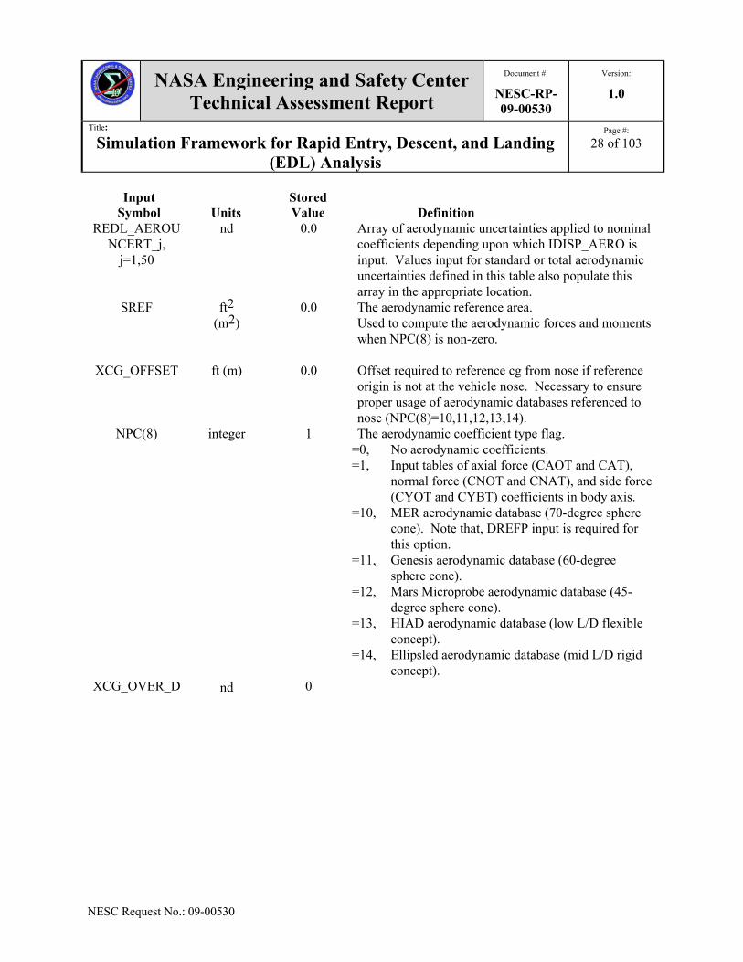
5.1.6 Aerodynamic Models Inputs and Outputs in POST2
This section presents the input associated with the aerodynamic characteristics of the five different vehicle geometries presented in Sections 5.1.1 through 5.1.5. The aerodynamic coefficients are obtained from subroutines developed from detailed aerodynamic databases. Also, these databases are referenced to the vehicle nose. Thus, the XCG_OFFSET must be used to adjust the XCG if the body reference frame origin is not the nose. Two options are available for where the aerodynamics is dispersed: at the reference point or at the vehicle cg. The total aerodynamic coefficients (total Axial force, CAT; total Normal Force, CNT; and total Pitching moment, CMT) are dispersed at the reference point, or the vehicle nose for the aerodynamic databases modeled in the current simulation. The standard aerodynamic

NASA Engineering and Safety Center Technical Assessment Report
Document #:
NESC-RP-09-00530
Version:
1.0
Title:
Simulation Framework for Rapid Entry, Descent, and Landing (EDL) Analysis
Page #:
24 of 103
NESC Request No.: 09-00530
coefficients (Axial force, CA; Normal force, CN, Side force, CY; Pitching moment Cm; Yawing moment, Cn or Cw; rolling moment, Cl or Cll) are dispersed at the vehicle cg. Also, two types of dispersions can be applied: a multiplier and an adder. The multiplier input (designated with a _MULT at the end of the input variable) is added to one and then multiplied to the associated nominal aerodynamic coefficient. The adder input (designated with an ADD at the end of the input variable) is added directly to the associated aerodynamic coefficient. The dispersions are input in specific flight regimes. The static coefficient dispersions are input in three main regions of the flight regime: free molecular, hypersonic continuum, and supersonic continuum. The free molecular flight regime is defined by Knudsen number values of 1000 and higher (indicated by _UNC1 in the variable name). For Knudsen number less than 1000, the hypersonic continuum is defined by Mach numbers of 10 and less (_UNC2 in variable name) until Mach number is less than 5, where the supersonic continuum region is defined (_UNC3 in variable name). The transitional aerodynamic uncertainties are determined using linear interpolation. Interpolation using log base 10 of Knudsen number is applied between free molecular and supersonic continuum dispersion values; whereas, interpolation using Mach number is utilized between hypersonic and supersonic continuum dispersion values. The only difference for dynamic derivative coefficient dispersions is that the hypersonic continuum is defined by Mach numbers below 6 and supersonic continuum is Mach number 3 and less. The general variables given in Table 5.1.6.1 are associated with the aerodynamic inputs, whereas Table 5.1.6.2 are the outputs in POST2. As shown parenthetically in the table below, similar dispersed values are available for the other flight regimes with the variable name changed (specifically the _UNC1 portion) as described previously; the only exception to this information is the CMQ_CWR_UNC3_MULT.

NASA Engineering and Safety Center Technical Assessment Report
Document #:
NESC-RP-09-00530
Version:
1.0
Title:
Simulation Framework for Rapid Entry, Descent, and Landing (EDL) Analysis
Page #:
25 of 103
NESC Request No.: 09-00530
Table 5.1.6.1. POST2 Inputs for the Aerodynamic Models in the Simulation Architecture for Rapid EDL Systems Analysis Studies
Input Symbol
Units
Stored Value
Definition
CAT_UNC1_M
ULT
(UNC2 &UNC3)
nd
0.0
Axial force coefficient multiplicative uncertainty in free molecular flight regime. For IDISP_AERO=1, dispersion value of total Axial force coefficient. For IDISP_AERO=2, standard Axial force coefficient.
(Hypersonic and Supersonic flight regimes)
CAT_UNC1_
ADD
(UNC2 &UNC3)
nd
0.0
Axial force coefficient additive uncertainty in free molecular flight regime. For IDISP_AERO=1, dispersion value of total Axial force coefficient. For IDISP_AERO=2, standard Axial force coefficient.
(Hypersonic and Supersonic flight regimes)
CMQ_CWR_ UNC1_ADD
(UNC2 &UNC3)
nd 0.0 Pitch damping and yaw moment damping due to yaw rate additive dispersion values for free molecular flight regime. Same value is applied to both dynamic derivatives.
(Hypersonic and Supersonic flight regimes)
CMQ_CWR_ UNC3_MULT
nd 0.0 Pitch damping and yaw moment damping due to yaw rate multiplicative dispersion values in supersonic flight regime. Same value is applied to both dynamic derivatives.
CMT_UNC1_M
ULT
(UNC2 &UNC3)
nd
0.0
Pitching moment coefficient multiplicative uncertainty in free molecular flight regime. For IDISP_AERO=1, dispersion value of total Pitching moment coefficient. For IDISP_AERO=2, standard Pitching moment coefficient dispersion at cg.
(Hypersonic and Supersonic flight regimes)

NASA Engineering and Safety Center Technical Assessment Report
Document #:
NESC-RP-09-00530
Version:
1.0
Title:
Simulation Framework for Rapid Entry, Descent, and Landing (EDL) Analysis
Page #:
26 of 103
NESC Request No.: 09-00530
Input Symbol
Units
Stored Value
Definition
CMT_UNC1_
ADD
(UNC2 &UNC3)
nd
0.0
Pitching moment coefficient additive uncertainty in free molecular flight regime. For IDISP_AERO=1, dispersion value of total Pitching moment coefficient. For IDISP_AERO=2, standard Pitching moment coefficient dispersion at cg.
(Hypersonic and Supersonic flight regimes)
CNT_UNC1_M
ULT
(UNC2 &UNC3)
nd
0.0
Normal force coefficient multiplicative uncertainty in free molecular flight regime. For IDISP_AERO=1, dispersion value of total Normal force coefficient. For IDISP_AERO=2, standard Normal force coefficient dispersion at cg.
(Hypersonic and Supersonic flight regimes)
CNT_UNC1_
ADD
(UNC2 &UNC3)
nd
0.0
Normal force coefficient additive uncertainty in free molecular flight regime. For IDISP_AERO=1, dispersion value of total Normal force coefficient. F or IDISP_AERO=2, standard Normal force coefficient dispersion at cg.
(Hypersonic and Supersonic flight regimes)
CW_UNC1_
MULT
(UNC2 &UNC3)
nd
0.0
Yawing moment coefficient multiplicative uncertainty at cg in free molecular flight regime. Only used when IDISP_AERO=2.
(Hypersonic and Supersonic flight regimes)
CW_UNC1_
ADD
(UNC2 &UNC3)
nd
0.0
Yawing moment coefficient additive uncertainty at cg in free molecular flight regime. Only used when IDISP_AERO=2.
(Hypersonic and Supersonic flight regimes)

NASA Engineering and Safety Center Technical Assessment Report
Document #:
NESC-RP-09-00530
Version:
1.0
Title:
Simulation Framework for Rapid Entry, Descent, and Landing (EDL) Analysis
Page #:
27 of 103
NESC Request No.: 09-00530
Input Symbol
Units
Stored Value
Definition
CY_UNC1_
MULT
(UNC2 &UNC3)
nd
0.0
Side force coefficient multiplicative uncertainty at cg in free molecular flight regime. Only used when IDISP_AERO=2.
(Hypersonic and Supersonic flight regimes)
CY_UNC1_
ADD
(UNC2 &UNC3)
nd
0.0
Side force coefficient additive uncertainty at cg in free molecular flight regime. Only used when IDISP_AERO=2.
(Hypersonic and Supersonic flight regimes)
DREFR DREFP DREFY
ft (m)
0.0 The reference diameter for roll, pitch, and yaw, respectively. Used to calculate the aerodynamic moments in roll, pitch, and yaw, respectively (6D).
IDISP_AERO Integer 0 Flag to generate dispersed aerodynamics. =0, use nominal (un-dispersed) aerodynamic
coefficients =1, disperse total aerodynamics at reference point first
and then decompose into standard coefficients; i.e., apply aerodynamic dispersion at vehicle reference point.
=2, decompose into standard coefficients, then disperse them at center of gravity; i.e., apply aerodynamic dispersion at vehicle cg.
LREF ft (m)
0.0 The reference length used in the calculation of Reynolds and Knudsen numbers.
LREFY ft (m)
0.0 The reference length in yaw. Used in the 3D yaw static trim equations.
MOLECULAR_WEIGHT
Kg/mole
0.02897 Atmospheric molecular weight (Earth 28.97 g/mole, Mars 43.45 g/mole). Used in Knudsen number calculation.
NOMINAL_ MOLECULE_ DIAMETER
m (ft)
3.78e-10 Nominal atmospheric molecule diameter (Earth 3.78e-10 m, Mars 4.64e-10 m). Used in Knudsen number calculation.
NASA Engineering and Safety Center Technical Assessment Report
Document #:
NESC-RP-09-00530
Version:
1.0
Title:
Simulation Framework for Rapid Entry, Descent, and Landing (EDL) Analysis
Page #:
28 of 103
NESC Request No.: 09-00530
Input Symbol
Units
Stored Value
Definition
REDL_AEROUNCERT_j,
j=1,50
nd 0.0 Array of aerodynamic uncertainties applied to nominal coefficients depending upon which IDISP_AERO is input. Values input for standard or total aerodynamic uncertainties defined in this table also populate this array in the appropriate location.
SREF ft2 (m2)
0.0 The aerodynamic reference area. Used to compute the aerodynamic forces and moments when NPC(8) is non-zero.
XCG_OFFSET ft (m) 0.0 Offset required to reference cg from nose if reference origin is not at the vehicle nose. Necessary to ensure proper usage of aerodynamic databases referenced to nose (NPC(8)=10,11,12,13,14).
NPC(8) integer 1 The aerodynamic coefficient type flag. =0, No aerodynamic coefficients. =1, Input tables of axial force (CAOT and CAT),
normal force (CNOT and CNAT), and side force (CYOT and CYBT) coefficients in body axis.
=10, MER aerodynamic database (70-degree sphere cone). Note that, DREFP input is required for this option.
=11, Genesis aerodynamic database (60-degree sphere cone).
=12, Mars Microprobe aerodynamic database (45-degree sphere cone).
=13, HIAD aerodynamic database (low L/D flexible concept).
=14, Ellipsled aerodynamic database (mid L/D rigid concept).
XCG_OVER_D nd 0

NASA Engineering and Safety Center Technical Assessment Report
Document #:
NESC-RP-09-00530
Version:
1.0
Title:
Simulation Framework for Rapid Entry, Descent, and Landing (EDL) Analysis
Page #:
29 of 103
NESC Request No.: 09-00530
Table 5.1.6.2. POST2 Outputs from the Aerodynamic Models in the Simulation Architecture for Rapid EDL Systems Analysis Studies
Output Symbol
Type/ Units
Definition
CA_NOM nd Nominal Axial force coefficient CAT_NOM nd Nominal total Axial force coefficient CLL_NOM nd Nominal rolling moment coefficient
CLLP_NOM nd Nominal roll moment damping due to roll rate coefficient CLLR_NOM nd Nominal roll moment damping due to yaw rate coefficient CM_NOM nd Nominal pitching moment coefficient
CMQ_NOM nd Nominal pitch moment damping due to pitch rate coefficient CMT_NOM nd Nominal total pitching moment coefficient CN_NOM nd Nominal Normal force coefficient
CNT_NOM nd Nominal total Normal force coefficient CW_NOM nd Nominal yawing moment coefficient
CWP_NOM nd Nominal yaw moment damping due to roll rate coefficient CWR_NOM nd Nominal yaw moment damping due to yaw rate coefficient CY_NOM nd Nominal Side force coefficient CA_DIS nd Dispersed Axial force coefficient
CAT_DIS nd Dispersed total Axial force coefficient CLL_DIS nd Dispersed rolling moment coefficient
CLLP_DIS nd Dispersed roll moment damping due to roll rate coefficient CLLR_DIS nd Dispersed roll moment damping due to yaw rate coefficient
CM_DIS nd Dispersed pitching moment coefficient CMQ_DIS nd Dispersed pitch moment damping due to pitch rate coefficient CMT_DIS nd Dispersed total pitching moment coefficient CN_DIS nd Dispersed Normal force coefficient
CNT_DIS nd Dispersed total Normal force coefficient CW_DIS nd Dispersed yawing moment coefficient
CWP_DIS nd Dispersed yaw moment damping due to roll rate coefficient CWR_DIS nd Dispersed yaw moment damping due to yaw rate coefficient CY_DIS nd Dispersed Side force coefficient
KNUDSEN nd Knudsen Number XCG_OVER_D nd XCG location non-dimensionalized by DREFP. Used by MER
aerodynamic model (NPC(8)=10). References for Aerodynamic Models
5.1.1. Schoenenberger, Mark; Cheatwood, F. McNeil; and Desai, Prasun N.: “Static Aerodynamics of the Mars Exploration Rover Entry Capsule,” AIAA-2005-0056, January 2005.
5.1.2. Schoenenberger, Mark; Hathaway, Wayne; Yates, Leslie; and Desai, Prasun: “Ballistic

NASA Engineering and Safety Center Technical Assessment Report
Document #:
NESC-RP-09-00530
Version:
1.0
Title:
Simulation Framework for Rapid Entry, Descent, and Landing (EDL) Analysis
Page #:
30 of 103
NESC Request No.: 09-00530
Range Testing of the Mars Exploration Rover Entry Capsule,” AIAA-2005-0056, January 2005.
5.1.3. Desai, Prasun N. and Cheatwood, F. McNeil: “Entry Dispersion Analysis for the Genesis Sample Return Capsule,” Journal of Spacecraft and Rockets, Vol. 38, No. 3, May-June 2001.
5.1.4. Mitcheltree, R. A.; Moss, J. N.; Cheatwood, F. M.; Greene, F. A.; and Braun, R. D.: “Aerodynamics of the Mars Microprobe Entry Vehicles,” Journal of Spacecraft and Rockets, Vol. 36, No. 3, May-June 1999.
5.1.5. Chapman, G.T.; Mitcheltree, R.A.; and Hathaway, W.H.: “Transonic and Low Supersonic Static and Dynamic Aerodynamic Characteristics of the Stardust Sample Return Capsule,” AIAA Paper 99-1021, January 1999.
5.1.6. Cheatwood, F.; Winchenbach, G.; Hathaway, W.; Chapman, G.: “Dynamic Stability Testing of the Genesis Sample Return Capsule,” AIAA Paper 2000-1009, January 2000.
5.2 Guidance Algorithms
A key element in developing rapid vehicle simulations is the vehicle guidance, navigation, and control (GN&C). The vehicle guidance (i.e., the "driver") takes input from the navigation parameters and user input targeting information to send signals to the flight control system that will allow the vehicle to reach its destination (within the operating constraints). For this Phase 1 assessment, only perfect navigation, where navigated states are set to truth states in the simulation (currently effected via NPC(41)=1 in POST2), is provided. Vehicle attitude control is discussed in Section 5.4. The focus of this section, three entry guidance algorithms and a terminal descent guidance algorithm provide the ability for an entry-to-touchdown simulation and vehicle performance assessment. The targets for the guidance systems are one or more state vectors (position and velocity) and can be inertial or relative. Several entry guidance algorithms of varying fidelity have been included depending on the particular application. The Apollo-type Hybrid Predictor-Corrector Aerocapture Scheme (HYPAS) and Numerical Predictor-Corrector (NPC) are similar to the actual flight guidance systems. These guidances include internal calculations that approximate atmosphere and aerodynamic parameters making them high fidelity, but computationally intense and more sensitive to tune. The other entry guidance, referred to as the Theoretical guidance algorithm, is relatively easy to implement using POST2, assumes full knowledge of the atmosphere and aerodynamics, does not require long setup and runtimes, while still providing flight-like guidance commands (such as bank reversal times) for lower fidelity but more rapid assessment of EDL vehicles.
NASA Engineering and Safety Center Technical Assessment Report
Document #:
NESC-RP-09-00530
Version:
1.0
Title:
Simulation Framework for Rapid Entry, Descent, and Landing (EDL) Analysis
Page #:
31 of 103
NESC Request No.: 09-00530
5.2.1 Hybrid Predictor-Corrector Aerocapture Scheme Entry Guidance
The program contains a HYPAS guidance capability that is implemented to solve the aerocapture problem. HYPAS is an analytical predictor-corrector scheme originally developed for Aeroassist Flight Experiment (AFE) circa 1989. HYPAS was tested, compared, and evaluated against other guidance algorithms in 3 and 6 DoF computer-based simulations and was selected for the space flight test. Development of the flight code was on schedule until the AFE Program was cancelled. HYPAS was used in numerous human and robotic exploration mission studies performed at the Johnson Space Center (JSC) over the last 10 years for Earth and Mars and has proven to be robust to a wide variety of vehicle L/D, vehicle ballistic coefficient (m/CDS), atmospheres, entry conditions, and target orbits. HYPAS was considered for the Mars Surveyor Program 2001 mission, before aerocapture was eliminated from the mission plan. It was also considered for the CNES Mars 2005 Sample Return Orbiter, and the CNES Mars 2007 Premier Mission until aerocapture was eliminated from the mission plan. HYPAS was used in the Titan, Neptune, Venus, and Mars Aerocapture system analysis investigations and improvements have been made to increase performance and robustness. The guidance targets a lifting vehicle through the atmosphere to a desired exit orbit apoapsis and inclination (or plane) and uses an analytically derived control algorithm based on deceleration due to drag and altitude rate error feedback
Where L/D is the vehicle lift-to-drag ratio, cmd is the commanded bank angle, CL is the lift force coefficient, CD is the drag force coefficient, eq.gl is the bank angle of the equilibrium
glide, GD and G h and are user defined gains, h is altitude rate and h ref is a reference altitude
rate profile, q is dynamic pressure, D is drag force and Dref is a reference drag force profile. All references are computed and updated during flight. This analytic, non-iterative, on-the-fly approach leads to efficient code (~320 source lines in Fortran), minimal storage requirements, and fast and consistent execution times. Coupled with gain selection schemes, HYPAS is adaptable to changes in design. POST2 inputs and outputs for the HYPAS guidance algorithm use are given in Tables 5.2.1.1 and 5.2.1.2, respectively.
q
DDG
q
hhG
C
C
D
L refD
ref
hgleqD
Lcmd
..coscos

NASA Engineering and Safety Center Technical Assessment Report
Document #:
NESC-RP-09-00530
Version:
1.0
Title:
Simulation Framework for Rapid Entry, Descent, and Landing (EDL) Analysis
Page #:
32 of 103
NESC Request No.: 09-00530
Table 5.2.1.1. POST2 Inputs for the HYPAS Guidance Algorithm Input
Symbol
Units Stored Value
Definition
IGUID(14) integer 0 The HYPAS selection flag.
=11, Use HYPAS guidance
HP_AC_PHASE
integer 0 Aerocapture phase selection flag
= 0, Entry.
= 1, Capture
= 2, Exit
HP_FLAG1 Integer
0 Flag to limit bank angle command
HP_FLAG1 Integer
0 Flag to track when reversal has ended
HP_IFLAG_REV
Integer 0.0 = 1.0 Resets roll direction when reversal is finished
HP_PHI_NO_WEDGE
Desired bank angle
HP_HSGUID Kg/m3 0.0 Scale height input
Table 5.2.1.2. POST2 Outputs for the HYPAS Guidance algorithm Output Symbol
Type/ Units
Definition
HP_BNKCMD degree
Commanded Bank Angle
HP_COS_PHI_CMD
nd
Cosine of the commanded bank angle
HP_IBNKNUM
Integer
Bank reversal number
HP_BNK_SUM
Integer
Total number of reversals
HP_BNK_RATE
degree/second Bank angle rate
HP_PHI_NO_WEDGE
degree Desired bank angle
HP_DRAG_REF
N Reference Drag Force

NASA Engineering and Safety Center Technical Assessment Report
Document #:
NESC-RP-09-00530
Version:
1.0
Title:
Simulation Framework for Rapid Entry, Descent, and Landing (EDL) Analysis
Page #:
33 of 103
NESC Request No.: 09-00530
Output Symbol
Type/ Units
Definition
HP_RDOT_REF
m/s Reference radius time rate of change
HP_WEDGE degree Wedge angle between current plane and target plane HP_CP1 nd Equilibrium glide component of the bank control equation HP_CP2 N Drag component of the bank control equation HP_CP3 m/s Radial Velocity component of the bank control equation
HP_AIMIN nd Lower Corridor HP_AIMAX nd Upper Corridor HP_RHO_ST
D Kg/m3 Density estimate
HP_HS_EST m Scale height estimate HP_HREF_ES
T m Reference Altitude estimate
5.2.2 Numerical Predictor-Corrector
The EDL-SA guidance problem is to guide the spacecraft from Mars atmospheric interface to a precise landing at the specified site. To address this problem, the entry is separated into four segments. The first is from deorbit to range control initiation, the second is Phase 1 range control initiation to Phase 2 range control initiation, the third is Phase 2 range control to propulsive terminal descent initiation, and the fourth is propulsive terminal descent. The range control is separated into two phases to force the spacecraft to fly more lift up during the second range control, thus providing more altitude at propulsive terminal descent initiation. This NPC is for precision landing. The algorithm receives state conditions (position and velocity) from the onboard navigation system. This information is provided in both the planet-centered inertial (PCI) frame, and the planet-centered planet-fixed (PCPF) relative frame. In addition, the current bank angle and sensed accelerations in both PCI and PCPF coordinate systems are provided. The algorithm integrates the 3 DoF translational equations of motion using a fourth-order Runge-Kutta integration scheme. The algorithm includes several internal models of the environment and vehicle: Planet model - oblate spheroid described by equatorial and polar radius; Gravitation model - simple harmonic model; Vehicle Aerodynamics - typically either tables or database subroutine; Vehicle mass properties - nominal values; and Atmosphere model - either tables or subroutine (usually Global Reference Atmosphere Model or GRAM). The algorithm produces a control vector that is composed of bank angle magnitude and reversal times (i.e., times to switch the current sign of the bank angle). In addition, the algorithm produces a state history (i.e., range to target, energy, and time rate of change in energy). Since the predictor-corrector is called at relatively long intervals, this state information is used to modify the bank angle magnitude between updates. This alteration is performed in the outer
NASA Engineering and Safety Center Technical Assessment Report
Document #:
NESC-RP-09-00530
Version:
1.0
Title:
Simulation Framework for Rapid Entry, Descent, and Landing (EDL) Analysis
Page #:
34 of 103
NESC Request No.: 09-00530
loop by comparing the actual state conditions with the predicted states conditions and then modifying the bank angle command to better match the predicted and actual values. The supplied accelerometer values were used to modify the internally calculated atmospheric density value and aerodynamics. This NPC is based on the NPC described in Reference 5.2.1. The control parameters are determined phase by phase so that only one control is determined at a time. For Phase 1, the bank angle command is set to 0 degrees, and after updating the density profile and aerodynamic characteristics, the NPC returns. Once the acceleration reaches 1.25 g’s, the first range control phase is entered. This phase determines the bank angle that will provide the specified engine start altitude at a nominal initiation distance from the target. During this phase, the bank angle for velocity less than 2000 m/s is held at the nominal value. Once velocity drops below 2000 m/s, the bank angle to reach the desired engine initiation altitude is also determined. During this phase the range to target is modified such that the vehicle will land within the required error tolerance. Once the vehicle reaches this range, the terminal descent phase is entered. During this phase, the NPC is calculating the AOA required to reach the target. Note that this NPC provides the framework that will allow a knowledgeable POST2 user the capability to develop an NPC algorithm for different problems. That is, the guidance algorithm is structured in such a way that new problems can be implemented by changing select working routines. POST2 inputs for the current NPC are given in Table 5.2.2.1, POST2 table inputs are shown in Table 5.2.2.2, and POST2 outputs are listed in Table 5.2.2.3.

NASA Engineering and Safety Center Technical Assessment Report
Document #:
NESC-RP-09-00530
Version:
1.0
Title:
Simulation Framework for Rapid Entry, Descent, and Landing (EDL) Analysis
Page #:
35 of 103
NESC Request No.: 09-00530
Table 5.2.2.1. POST2 Inputs for the NPC Guidance Algorithm Input
Symbol Type/ Units
Stored Value
Definition
GVRC(1) degree/ second
0 Maximum bank angle rate during range control phases 1 and 2.
BNKMODE_PC Integer 0 Inside PC guidance model, flag to control Bank maneuver direction in the pseudo-controller = -2, bank through 180 degree (underneath) = -1, bank left = 0, go shortest distance = 1, bank right = 2, bank through 0 degree (over)
PSEUDO_CTRL_PC Integer 0 Inside the PC guidance model, the bank pseudo-controller overshoot mode selection flag
= 0, normal.
= 1, no overshoot
= 2, no wrong way
= -1, perfect
GVRC(3) degree 0 Target geocentric latitude
MAXACCEL_PC degree/
second 0 Maximum bank rate used by the bank angle pseudo-
controller in the PC guidance model.
MAXRATE_PC degree/ second2
0 Maximum bank acceleration used by the bank angle pseudo-controller in the PC guidance model.
PC_AZI_RES_GAIN
nd
0.0 The gain on azimuth error in the heading alignment phase of the PC guidance model.
PC_BCONTROL
nd
0.0 The sideslip angle control multiplier for the PC guidance model.
PC_DALT
nd
0.0 The desired altitude in segment 3 for the PC guidance model.
PC_DALTD
nd
0.0 The desired altitude rate in segment 3 for the PC guidance model.

NASA Engineering and Safety Center Technical Assessment Report
Document #:
NESC-RP-09-00530
Version:
1.0
Title:
Simulation Framework for Rapid Entry, Descent, and Landing (EDL) Analysis
Page #:
36 of 103
NESC Request No.: 09-00530
Input Symbol
Type/ Units
Stored Value
Definition
PC_DUSTTAU
nd
0.0 The atmospheric opacity factor used by the atmosphere model in the PC guidance model.
PC_DVELTD
ft/s (m/s)
0.0 The desired velocity in the terminal descent phase for the PC guidance model.
PC_FLGVELR
Integer
0 Flag to activate usage of VELR versus RANGE profile in the PC guidance model.
PC_GAEXIT(i) i=1,NGMXS
ft2 (m2)
0.0 The exit area for the engine in the PC guidance model, where NGMXS is the maximum number of segments (10).
PC_GGO
ft/s2 (m/s2)
0.0 The weight to mass conversion constant in the PC guidance model.
PC_GJi i=2,3,4
nd
0.0 The zonal gravity harmonics J2, J3, and J4 for the PC guidance model.
PC_GJDATE
days
0.0 The Julian date used for atmosphere model in the PC guidance model.
PC_GMU ft3/s2 (m3/s2)
MU The gravitational constant for the PC guidance model.
PC_GOMEGA rad/s OMEGA The rotation rate of the attracting planet for the PC guidance model.
PC_GRE ft (m)
RE The equatorial radius of the attracting planet for the PC guidance model.
PC_GRP ft (m)
RP The polar radius of the attracting planet for the PC guidance model.
PC_GSREF ft2 (m2)
RP The vehicle aerodynamic reference area used by the PC guidance model.
PC_GTVAC (i) i=1,NGMXS
lbm (N)
0 The engine vacuum thrust for the PC guidance model (NGMXS=10).

NASA Engineering and Safety Center Technical Assessment Report
Document #:
NESC-RP-09-00530
Version:
1.0
Title:
Simulation Framework for Rapid Entry, Descent, and Landing (EDL) Analysis
Page #:
37 of 103
NESC Request No.: 09-00530
Input Symbol
Type/ Units
Stored Value
Definition
PC_GISPV(i) i=1,NGMXS
s 1.0E10 The engine specific impulse for the PC guidance model (NGMXS=10).
PC_ENG_ START
ft (m)
0 The range at which to start the engines, according to the PC guidance model.
PC_PROFILE_ALT_VEL
integer
0 Altitude – Velocity profile flag. =0, no new profile =1, new alt versus vel profile for PC guidance
PC_RCALC_SET integer
0 Flag to initialize range calculations in PC guidance
Table 5.2.2.2. POST2 Table Inputs for the NPC Guidance Algorithm Input
Symbol Type/ Units
Stored Value
Definition
PC_DELZT degree 0 Azimuth error tolerance used in the PC guidance PC_CAT Nd 0 Axial force coefficient table used in the PC guidance PC_CDT Nd 0 Drag force coefficient table used in the PC guidance PC_CLT Nd 0 Lift force coefficient table used in the PC guidance PC_CNT Nd 0 Normal force coefficient table used in the PC guidance
Table 5.2.2.3. POST2 Outputs for the NPC Guidance Algorithm Output Symbol
Type/ Units
Definition
PC_ALT_LAN ft (m)
Altitude above landing site calculated in the PC guidance model.
PC_CA Nd Axial force coefficient used in the PC guidance model. PC_CD Nd Drag force coefficient used in the PC guidance model. PC_CL Nd Lift force coefficient used in the PC guidance model. PC_CN Nd Normal force coefficient used in the PC guidance model.
PC_CRANGE ft (m)
The cross range to target, according to the PC guidance model.
PC_DELZ degree Lookup value of the PC_DELZT table used in the PC guidance PC_DRANGE ft
(m)
The down range to target, according to the PC guidance model.
PC_DVELTD ft/s (m/s)
The desired velocity in the terminal descent phase according to the PC guidance model.

NASA Engineering and Safety Center Technical Assessment Report
Document #:
NESC-RP-09-00530
Version:
1.0
Title:
Simulation Framework for Rapid Entry, Descent, and Landing (EDL) Analysis
Page #:
38 of 103
NESC Request No.: 09-00530
Output Symbol
Type/ Units
Definition
PC_ENG_ MULT
nd
The engine throttle setting determined by the PC guidance model.
PC_ENG_ START
nd
The range at which to start the engines, according to the PC guidance model.
PC_GALPHA degree
The vehicle AOA, according to the PC guidance model.
PC_GGXI PC_GGYI PC_GGZI
ft/s2 (m/s2)
The gravity acceleration vector components along the XI, YI, and ZI axes, respectively, from the PC guidance model.
PC_GMACH nd
The vehicle Mach number, according to the PC guidance model.
PC_GVELR ft/s (m/s)
The vehicle relative velocity magnitude, according to the PC guidance model.
PC_HRATE nd
The vehicle aerodynamic heat rate, according to the PC guidance model.
PC_RAZIMUTH degree
The relative azimuth to target, according to the PC guidance model.
PC_RNG_RES degree
The range error used to calculate AOA during terminal descent in the PC guidance.
PC_TRANGE ft (m)
The total range to target, according to the PC guidance model.
5.2.3 Theoretical Entry Guidance
The program contains a theoretical guidance capability, meaning that the algorithm has full knowledge of all parameters (e.g., atmosphere, aerodynamics, etc.). The routine requires minimum formulation in an effort to be deliberatively conservative, while maintaining the capability to mimic the results of a “real” guidance algorithm. It is not the theoretical-best solution. The theoretical guidance is a realizable version of the pseudo guidance that was developed for the Design Reference Architecture (DRA) 5 study [References 5.1.2, 5.1.3]. The DRA 5 study simulation selected an initial bank angle and used linear feedback to maintain a constant 2 g’s deceleration during entry. The vehicle then flew full lift up (bank angle of 0 degrees) until an optimizer determined engine initiation, which was maintained at a constant 3 g’s deceleration using engine throttle setting until the vehicle reached a constant velocity phase. The entry deceleration constraint was used in the absence of Monte Carlo simulations performed for the

NASA Engineering and Safety Center Technical Assessment Report
Document #:
NESC-RP-09-00530
Version:
1.0
Title:
Simulation Framework for Rapid Entry, Descent, and Landing (EDL) Analysis
Page #:
39 of 103
NESC Request No.: 09-00530
DRA study and was considered sufficiently conservative to accommodate the entry dispersions and remain within the deconditioned crew constraints of approximately 4 g’s. The theoretical guidance algorithm is flexible to work for any architecture using a lifting body. It is based on proven flight guidance algorithms, including the Space Shuttle Program and Mars Science Laboratory (MSL), that include similar phases including entry, pull out, and heading alignment phases. POST2 inputs associated with the theoretical entry guidances are given in Table 5.2.3.1, whereas the outputs are in Table 5.2.3.2.
Table 5.2.3.1. POST2 Inputs for the Theoretical Guidance Algorithm Input
Symbol
Units Stored Value
Definition
IGUID(14) Integer 0 The theoretical guidance selection flag.
=12, Use theoretical guidance
TH_BANK_INIT degree 0.0 Initial bank angle TH_BANK_GAIN_
HA Nd 0.0 Bank angle gain during heading alignment phase
TH_BANK_LIMIT_HA
degree 0.0 Max bank angle limit during heading alignment phase
TH_VEL_HA m/s 0.0 Velocity to start heading alignment TH_GUID_PICK_B
NKDIR Integer 0 Allows guidance to select initial bank direction
= 1, let guidance pick bank direction TH_BNKDIR integer 0 Initial Bank Direction
= 1, bank right =-1, bank left
TH_GUID_INIT Integer 0 Activate guidance = 0, guidance off = 1, guidance on
TH_HA_INIT Integer 0 Start heading alignment phase = 1, begin heading alignment
TH_LOCK_AZIM_PD
Integer 0 Lock azimuth at powered descent = 1, Lock azimuth
TH_SET_DELAZ_PAST_TARG
Integer 0 Designates that if landing target has been over flown, delaz is set to 0 = 1, set delaz to 0 if target is overflown
TH_USE_INPLANE_TARG
Integer 0 Use in plane targeting (for use with entry vehicle mass models) must also set th_lock_azim_pd =1 = 1, guidance on

NASA Engineering and Safety Center Technical Assessment Report
Document #:
NESC-RP-09-00530
Version:
1.0
Title:
Simulation Framework for Rapid Entry, Descent, and Landing (EDL) Analysis
Page #:
40 of 103
NESC Request No.: 09-00530
Input Symbol
Units
Stored Value
Definition
TH_BNK_CTRL_INIT
Integer 0 Activates bank control = 0, guidance off = 1, guidance on
TH_GUID_CRRNG_OFFSET
Decimal 0.0 Value for cross range offset when performing divert maneuvers
Table 5.2.3.2. POST2 Outputs for the Theoretical Guidance Algorithm Output Symbol
Type/ Units
Definition
TH_TOTAL_RANGE km
Total range calculated in motion.f every dt using rangeg.f
TH_CROSSRANGE km
Cross range calculated in motion.f every dt using rangeg.f
TH_DOWNRANG km
Down range calculated in motion.f every dt using rangeg.f
TH_TARG_AZ degree
Azimuth to the target calculated in motion.f every dt using rangeg.f
TH_DELAZ degree
Vehicle azimuth – azimuth to target calculated in motion every dt.
TH_GUID_TOTAL_RANGE km
Total range calculated in thguid.f using rangeg.f only when guidance is active
TH_GUID_CROSSRANGE km
Cross range calculated in thguid.f using rangeg.f only when guidance is active
TH_GUID_DOWNRANG km
Down range calculated in thguid.f using rangeg.g only when guidance is active
TH_GUID_TARG_AZ degree
Azimuth to the target calculated in thguid.f every dt using rangeg.f
TH_GUID_DELAZ deg
Vehicle azimuth minus azimuth to the target calculated in thguid.f from rangeg.f only when guidance is active
TH_BNKCMD degree
Commanded bank angle
TH_LON_GUID_INIT degree
Longitude at guidance initiation
TH_LAT_GUID_INIT degree
Latitude at guidance initiation

NASA Engineering and Safety Center Technical Assessment Report
Document #:
NESC-RP-09-00530
Version:
1.0
Title:
Simulation Framework for Rapid Entry, Descent, and Landing (EDL) Analysis
Page #:
41 of 103
NESC Request No.: 09-00530
5.2.3.1 Gravity Turn Terminal Descent Guidance
A gravity turn guidance capability was included for use during an all-propulsive terminal descent phase of an EDL. The routine is based on the use of gravity to turn the vehicle velocity and thrust to control the vehicle velocity magnitude.
5.2.3.2 Theoretical Background
The governing equation of motion can be written as:
gTm
V
1
During the powered portion of the terminal descent, vehicle dynamics are dominated by the propulsive thrust and drag is neglected. In order to solve the problem, the vector equation of motion must be written in scalar form. The free-body diagram of a gravity turn is shown in Figure 5.2.3.1.
Figure 5.2.3.1. Gravity Turn Guidance Free-Body Diagram By definition, the velocity vector, V, in Figure 5.2.3.1 is the atmospheric relative velocity vector. However, since the atmospheric winds are usually not known, the planet relative velocity vector is used. The primary constraint of a gravity turn is that the thrust vector is directed opposite to the relative velocity vector. A detailed derivation is given in Appendix A. From this derivation, the main guidance equations can be written as:

NASA Engineering and Safety Center Technical Assessment Report
Document #:
NESC-RP-09-00530
Version:
1.0
Title:
Simulation Framework for Rapid Entry, Descent, and Landing (EDL) Analysis
Page #:
42 of 103
NESC Request No.: 09-00530
tgo V
Tsf I T m gIcos (5.2.3.1)
2
cos000 2
1cos go
mTsfgof tIITgtVhhh
(5.2.3.2)
Where the thrust is solved via a throttle parameter () and the three integrals (I(T/m), Icosq,
II(T/m)cosq) only depend on the assumed flight path angle and the desired thrust-to-mass profiles. The actual value of these integrals may be calculated off-line or as a separate subroutine and supplied to the guidance algorithm as parameters or gains.
The order in which Equations 5.2.3.1 and 5.2.3.2 are solved depend upon the mode in which the guidance is operating. There are two guidance modes: a predictive mode in which the guidance is estimating the time-to-go and altitude loss for the assumed thrust profile, and a proactive mode in which the guidance determines the throttle setting required to achieve the terminal conditions. The predictive mode is used for determining the initiation of the powered descent, whereas the proactive mode is used to guide the vehicle during the powered descent.
The predictive guidance mode is used for determining the initiation of the powered descent by comparing the predicted altitude loss to the current altitude condition. This mode allows missions designers the option of a “smart” powered descent initiation in which the guidance algorithm is used to initiate the powered descent when the required throttle setting has a pre-defined level. The desired throttle setting is chosen to minimize fuel requirements while maintaining sufficient thrust margins. The time-to-go given the required change in velocity (actual velocity less the target velocity) and the desired throttle setting is determined. When the predicted altitude loss exceeds the available altitude loss (actual altitude less the target altitude), the initiation of powered descent should be commanded.
The proactive guidance mode is the primary mode used to guide the vehicle during the powered descent. In this mode, the guidance calculates the thrust magnitude (throttle setting) needed to achieve the desired terminal altitude and velocity conditions. The desired direction of the thrust vector is along the anti-velocity vector. This calculation is repeated at each guidance interval during the powered descent.
When a constant T/m profile is used, the three profile integrals evaluate to:
Icos cosd0
1
sin0
0

NASA Engineering and Safety Center Technical Assessment Report
Document #:
NESC-RP-09-00530
Version:
1.0
Title:
Simulation Framework for Rapid Entry, Descent, and Landing (EDL) Analysis
Page #:
43 of 103
NESC Request No.: 09-00530
I Tm
ˆ T
m
0
1
d ˆ T
m
0
II Tm cos
ˆ T
m
cosd 2
0
1
0
1
ˆ T
m
0
1 cos0 0
2
Where 0 is related to the initial flight path angle.
When linear thrust and off-vertical angle () profiles are assumed, the three profile integrals become
For
and
which leads to:
Thus, once a profile is assumed, the constants and integrals can be evaluated and guidance commands (throttle setting) generated.
5.2.3.3 Usage Guidelines
This implementation of the gravity turn guidance assumes one main engine is used (engine number 1) and that it is always oriented such that the thrust is along the positive body X-axis (i.e., pi1t is set to 180). Relative aerodynamic angles must be used (iguid(1)=9) and ALPHR, BETAR, and BANKR are set to zero (IGUID(3)=1, ALPPC=0, BETPC=0, BNKPC=0). Thrust modulation is controlled through the throttling variable ETA (NPC(22)=2 is required); note that ETA is limited to be 1.0 or less. Navigated altitude (GDALTN), relative velocity (VELRN), and relative flight path angle (GAMMARN) are used by this guidance (note that NPC(41)=1 currently populates these variables with their corresponding truth values if no navigation system
ˆ T
m C0 Cx
I Tm
ˆ T
m
0
1
d C0 1
2Cx
0 0Icos cosd
0
1
sin0
0
II Tm cos
ˆ T
m
cosd 2
0
1
0
1
C0
cos0 0 sin0 1 0
2 Cx
2sin0 0 cos0 0 0
3
C0 ˆ T
m
0
Cx ˆ T
m
1
ˆ T
m
0

NASA Engineering and Safety Center Technical Assessment Report
Document #:
NESC-RP-09-00530
Version:
1.0
Title:
Simulation Framework for Rapid Entry, Descent, and Landing (EDL) Analysis
Page #:
44 of 103
NESC Request No.: 09-00530
is in use). POST2 input variables and values associated with the gravity turn guidance are given in Table 5.2.3.3, while the outputs are in Table 5.2.3.4.
Table 5.2.3.3. POST2 Inputs for the Gravity Turn Terminal Guidance Algorithm Input
Symbol Units/
Type Stored Value
Definition
IGUID(1) integer 0 The attitude definition flag. Must be set to be
=9, Use relative aerodynamic angles
IGUID(14) integer 0 The guidance selection flag.
=14, Use gravity turn guidance
GT_G m/s2 0.0 Surface gravity magnitude used internal to the gravity turn guidance.
GT_HTARG m 0.0 Target geodetic altitude for end of gravity turn segment.
GT_ISP s 0.0 Engine specific impulse used internal to gravity turn guidance model.
GT_MIN_ THRUST
N 0 Minimum allowable thrust for gravity turn computations
GT_MODE ND 0 Gravity turn model mode. =0, Predict mode =1, Execute mode =2, Hold constant velocity mode
GT_THRUST_ PROFILE
integer 0 The thrust profile shape model to use for the gravity turn guidance =0, Constant thrust-to-weight profile =1, Linear thrust-to-weight and flight path angle profiles
GT_THRUST_ TYPE
Integer 0 Type of thrust-to-weight profile =0. Use thrust-to-mass =1, use thrust-to-weight
GT_VTARG m/s 0.0 Target relative velocity at HTARG altitude (end of the gravity turn guidance segment).
NPC(22) nd 0 The throttling parameter input option flag. Used if NPC(9)=1,2, and NPC(30)=0,3,4. For Gravity Turn guidance, it must be set to be =2, The throttling parameter (ETA) is obtained by evaluating a cubic polynomial with constant term coming from ETAPC(1).

NASA Engineering and Safety Center Technical Assessment Report
Document #:
NESC-RP-09-00530
Version:
1.0
Title:
Simulation Framework for Rapid Entry, Descent, and Landing (EDL) Analysis
Page #:
45 of 103
NESC Request No.: 09-00530
Table 5.2.3.4. POST2 Outputs for the Gravity Turn Terminal Guidance Algorithm Output Symbol
Type/ Units
Definition
ETA nd
Throttle setting for engine determined by gravity turn guidance (iguid(14)=14)
GT_ACCEL_CMD m/s2
Required acceleration at current location to follow a gravity turn trajectory from current location.
GT_ALT_LOSS m
Predicted altitude loss if gravity turn guidance used starting from current time and location.
GT_ALTITUDE m
Current altitude used by the gravity turn guidance.
GT_ASMXj, j=1,3 m/s2
Current vehicle sensed acceleration used by the gravity turn guidance
GT_MASS kg
Current vehicle mass used by gravity turn guidance.
GT_THRUST_CMD N
Required thrust at current location to follow a gravity turn trajectory from current location.
GT_VELR m/s
Current vehicle relative velocity magnitude used by the gravity turn guidance.
References for Guidance Algorithms 5.2.1. Powell, R.W.: "Numerical Roll Reversal Predictor-Corrector Aerocapture and Precision
landing Guidance Algorithms for the Mars Surveyor Program 2001 Missions." AIAA 98-4574, Presented at the 1998 AIAA Atmospheric Flight Mechanics Conference, Boston, MA. August 10-12, 1998.
5.2.2. Drake, Bret G., editor. “Human Exploration of Mars Design Reference Architecture 5.0”. Johnson Space Center, Houston TX, June 2009. NASA/SP-2009-566.
5.2.3. Drake, Bret G., editor. “Human Exploration of Mars Design Reference Architecture 5.0 Addendum”. Johnson Space Center, Houston TX, June 2009. NASA/SP-2009-566-ADD.
5.3 Mass Models
The purpose of the mass modeling task was to equip the standard POST2 code with the capability of utilizing mass metamodels (e.g., response surfaces, neural networks, table look-ups, kriging models, etc.) for standard trajectory analysis. This capability allows the user to simultaneously design both the trajectory and an appropriately sized vehicle capable of following the intended trajectory. The standard POST2 calculation routines were preserved wherever possible when implementing the mass model subroutines. The intent of the architecture was to

NASA Engineering and Safety Center Technical Assessment Report
Document #:
NESC-RP-09-00530
Version:
1.0
Title:
Simulation Framework for Rapid Entry, Descent, and Landing (EDL) Analysis
Page #:
46 of 103
NESC Request No.: 09-00530
avoid a high degree of coupling between the mass model subroutines and the standard POST trajectory functions. The metamodels must be developed externally to the POST2 framework and then inserted into the massEDL.f routine. Although summarized here, further information about the mass model can be found in Appendix B.
5.3.1 Basic Operation Using EDLSA Mass Model
The user begins by entering the necessary mass and trajectory input variables and initial values for the targeting algorithm. Instead of reading a deterministic mass or weight from the input deck, mass model input information is collected and used to determine the initial component masses (e.g., the aeroshell, descent stage, aeroshell reaction control system (RCS), etc.). These component masses are used to set the stage weights (WGTSG(i)) using the vehicle component weight model (NPC(30)=3 or 4). After the stage weights are set in massEDL.f, the POST2 trajectory is then allowed to run as normal. In the final usable phase (i.e., just before the final event), the mass convergence routine that resides in the special calculations routine (calspe.f) is called. This routine examines the mass results from the trajectory and computes the convergence variables. The standard target algorithms (i.e., projected gradient or NPSOL) are used to determine if convergence has been attained. If not, the mass control variables are iterated and the process repeats. Once convergence has been reached, the program outputs a standard output deck containing the standard trajectory and mass variables. Several mass models were developed which simulate various EDL technology packages currently under consideration for landing large payloads on the Martian surface. The simulations currently available to the user include:
- An ellipsled rigid aeroshell model and associated RCS model
- A flexible, inflatable aeroshell model (MIAS - the Mars Inflatable Aeroshell System) and associated RCS model
- An unconstrained all propulsive model with no aeroshell or TPS The aeroshell mass models account for the structural and TPS masses. The all-propulsive case uses only rocket propulsion to land a payload on the Martian surface. All the cases include an appropriate descent stage mass model and use the desired mission payload as the mass dependent (target) variable while the entry mass is used as the mass independent (control) variable. The all-propulsive case has no maximum heat rate or heat load constraints (i.e., it is an unconstrained model) to improve usability and maintain simplicity. Several input variables must be configured in a specific fashion for the mass models to correctly function as currently defined:

NASA Engineering and Safety Center Technical Assessment Report
Document #:
NESC-RP-09-00530
Version:
1.0
Title:
Simulation Framework for Rapid Entry, Descent, and Landing (EDL) Analysis
Page #:
47 of 103
NESC Request No.: 09-00530
- MEDL_MPLCALC must be used as a dependent variable in the input deck. The target value of MEDL_MPLCALC must be set equal to the desired delivered payload mass (in kg) in the final phase.
- MEDL_MPL must be set as an independent variable in the input deck in the first phase with the index (INDXI(i)) set to a negative value (i.e., if MEDL_MPL is the 4th independent variable, then the index must be set to -4 not 4; this ensures the value of MEDL_MPL is not changed by the targeting algorithm). Note also that the independent variable guess (INDVAL(i)) must be set to the desired delivered payload mass (in kg).
- MEDL_MGUESS must be set as an independent variable in the first phase with appropriately wide bounds. The independent variable guess (INDVAL(i)) is the initial entry mass guess used by the mass subroutines for the first iteration.
- MEDL_MTOGGLE must be set to the value corresponding to the desired mass model (i.e., ellipsled, all propulsive, etc.) in the first event.
- MEDL_MCONV must be set equal to unity in its own instantaneous event immediately preceding the final event. - If the last functional event is event 980 and the final event is 999, then
MEDL_MCONV = 1 in event 990. Nothing else should occur in event 990. - Event 990 should be instantaneous: CRITR = TDURP and VALUE = 0
- For all given simulations; set MONX(2) = ASMG such that XMAX(2) is the maximum sensed acceleration. This measurement is used for structural loads analysis and is required to correctly determine the descent stage structural mass.
Inputs required to execute the three simulation types mentioned above include:
- For the Ellipsled Simulation (MEDL_MTOGGLE ≤ 1): - MALTA and MALTP must be entered so that orbital period may be computed (used
for ellipsled aeroshell mass computations). - LREF, the aerodynamic reference length, is required to compute the ellipsled
aeroshell mass. - For the MIAS Simulation (MEDL_MTOGGLE =2):
- No additional inputs required outside of the six items discussed previously - For the All Propulsive Simulation (MEDL_MTOGGLE = 3):
- The all propulsive simulation reads specific impulse using NETISP. The user must ensure that the value of NETISP throughout the simulation is consistent with the desired specific impulse
5.3.2 Mass Model Input Variable Ranges
In addition to the previously specified requirements, the user must ensure that the bounds of the default or user-defined mass models are not violated either at the outset of a simulation (by the initial conditions) or by the final converged masses. This is especially crucial for simulations

NASA Engineering and Safety Center Technical Assessment Report
Document #:
NESC-RP-09-00530
Version:
1.0
Title:
Simulation Framework for Rapid Entry, Descent, and Landing (EDL) Analysis
Page #:
48 of 103
NESC Request No.: 09-00530
involving multiple mass models which pass information between one another. Since this coordination task is tedious and time consuming, formulation of a spreadsheet application which can be used to check for input variable bound violations is recommended. Such an application has been developed for the provided default mass models; see the POST2 Mass Model User’s Handbook for more information.
If boundary violations are permitted to occur, one or more mass models will return extrapolated data. Metamodels with a high degree of fitting accuracy may experience a rapid loss of accuracy beyond the stated model boundaries. This phenomenon may be due to many causes including model overfitting, a highly complex design space, non-linear changes in the physical behavior of the real system which the model cannot predict, etc. Extrapolation of complex metamodels is strongly discouraged. The following subsections include model boundaries that apply to the included default mass metamodels.
5.3.2.1 Ellipsled Mission Variable Bounds (MEDL_MTOGGLE ≤ 1)
Table 5.3.2.1. Ellipsled Descent Stage Inert Mass Response Surface Independent Variable Ranges
Variable Minimum Baseline Maximum Units Comments
Descent ΔV 500 1250 2000 m/s Ideal ΔV based on constant Isp
Deorbit ΔV 0 25 50 m/s Ideal ΔV based on constant Isp
T/W_system 3 4.5 6 Earth g’s T/W_engine 30 60 90 Mission Payload Mass 20 45 70 mT Aeroshell Mass 30 50 70 mT
Descent Stage Notes: 1) The descent ΔV (VIDEAL-DVIMAG) and deorbit ΔV (DVIMAG) are automatically read from the output
deck. This assumes that the deorbit ΔV is modeled as instantaneous. 2) The T/W_system is read from XMAX(2) as stated above 3) The T/W_engine is mass model specific and is hard-coded in calspe.f. Currently, T/W_engine = 80 for all
default models (based on DRA 5.0 and 6.0). 4) The mission payload mass is input by the user as MEDL_MPL 5) The aeroshell mass is computed by the mass model calculation routine; this parameter should not be out of
bounds as long as the aeroshell input parameters are within the appropriate bounds. The stated aeroshell ranges include both the aeroshell itself and its associated RCS.
Ellipsled Table Look-Up Independent Variable Ranges
- MEDL_MPL must be a discrete value equal to 20,000, 40,000, or 70,000 kg - The ellipsled reference length (LREF) must be a discrete value equal to either 10 or 12 m

NASA Engineering and Safety Center Technical Assessment Report
Document #:
NESC-RP-09-00530
Version:
1.0
Title:
Simulation Framework for Rapid Entry, Descent, and Landing (EDL) Analysis
Page #:
49 of 103
NESC Request No.: 09-00530
- MALTA and MALTP must be entered to allow the orbital period to be calculated RCS Model Independent Variable Ranges This model is a simple linear regression of the RCS mass based on robotic mission entry masses. Due to the change in scale between the entry masses of Discovery and Exploration class missions, extrapolation is unavoidable. Therefore, no model boundaries are applicable in this case. Thrust Specific Impulse Value Restriction The ellipsled simulation is only valid for a specific impulse of 369 seconds corresponding to a liquid oxygen (LOX)/methane (CH4) propellant combination.
5.3.2.2 MIAS Mission Variable Bounds (MEDL_MTOGGLE = 2)
Table 5.3.2.2. MIAS Descent Stage Inert Mass Response Surface Independent Variable Ranges
Variable Minimum Baseline Maximum Units Comments
Descent ΔV 200 1100 2000 m/s Ideal ΔV based on constant Isp
Deorbit ΔV 0 25 50 m/s Ideal ΔV based on constant Isp
T/W_system 1 3.5 6 Earth g’s T/W_engine 30 60 90 Mission Payload Mass 20 45 70 mT
Aeroshell Mass 0.7 5.35 10 mT based on available MIAS test data
Descent Stage Notes: 1) The descent ΔV (VIDEAL-DVIMAG) and deorbit ΔV (DVIMAG) are automatically read from the
output deck. This assumes that the deorbit ΔV is modeled as instantaneous. 2) The T/W_system is read from XMAX(2) as stated previously 3) The T/W_engine is mass model specific and is hard-coded in calspe.f. Currently, T/W_engine = 80 for
all default models (based on DRA 5.0 and 6.0). 4) The mission payload mass is input by the user as MEDL_MPL 5) The aeroshell mass is computed by a simple regression model. The stated aeroshell ranges include
both the aeroshell itself and its associated RCS. MIAS and MIAS RCS Independent Variable Ranges The MIAS inflatable aeroshell is computed from two simple linear regression models; one for the aeroshell mass itself and one for the RCS system mass. The only input to these models is the entry mass (MEDL_MGUESS). According to the Astrium report (see Reference 5.3.1) from which the model data was drawn, both the MIAS aeroshell and associated RCS models are valid for entry masses between 6 and 70 mT. However, due to the simplicity of the linear model, extrapolation yields result, which are as accurate than results from within the model bounds.

NASA Engineering and Safety Center Technical Assessment Report
Document #:
NESC-RP-09-00530
Version:
1.0
Title:
Simulation Framework for Rapid Entry, Descent, and Landing (EDL) Analysis
Page #:
50 of 103
NESC Request No.: 09-00530
It is important to note, however, that while the bounds for the MIAS aeroshell and RCS models are not strict, the model bounds for the MIAS descent stage are stringent. The maximum total decelerator (aeroshell + RCS) mass which the descent stage model can accommodate is 10 mT. This corresponds to a maximum allowed entry mass (MEDL_MGUESS) of roughly 66.9 mT. Entry masses higher than this will force the descent stage model to extrapolate beyond its intended ranges. While extrapolation of any response surface is discouraged, the sensitivity of the descent stage inert mass to the aeroshell mass is low for the given ranges. In fact, due to its low statistical significance, the aeroshell mass does not directly appear in the response surface. Therefore, small extrapolations beyond 10 mT (up to 15 mT) may be considered in this case. See the POST2 Mass Model User’s Handbook for more information. Thrust Specific Impulse Value Restriction The MIAS simulation is only valid for a specific impulse of 369 seconds corresponding to a LOX/CH4 propellant combination.
5.3.2.3 All Propulsive Mission Variable Bounds (MEDL_MTOGGLE = 3)
Table 5.3.2.3. Propulsive Mission Descent Stage Inert Mass Response Surface Independent Variable Ranges
Variable Minimum Maximum Baseline Units Isp 369 900 634.5 sec T/W engine 80 200 140
T/W system 1 4 2.5Earth g’s
Total ΔV 3000 6000 4500 m/s Descent Stage Notes:
1) The descent stage specific impulse (Isp) is read from the POST2 output variable NETISP; check to ensure that the NETISP history is consistent with the desired Isp.
2) The T/W_engine is mass model specific and is hard-coded in calspe.f. Currently, T/W_engine = 80 for all default models (based on DRA 5.0 and 6.0).
3) The T/W_system is read from XMAX(2) as stated previously 4) Total ΔV is equivalent to VIDEAL; no distinction between descent and deorbit ΔV are required for the all
propulsive case since no masses (e.g., aeroshell, etc) are staged and the descent stage payload remains consistent throughout the entire simulation.
Payload Mass Limitation The all-propulsive simulation is only valid for a payload mass of 40 mT.
5.3.3 Mass Models POST2 Inputs/Outputs
Test cases were developed which employ these mass model in a variety of scenarios. These scenarios correspond to various EDL technology packages currently under consideration for

NASA Engineering and Safety Center Technical Assessment Report
Document #:
NESC-RP-09-00530
Version:
1.0
Title:
Simulation Framework for Rapid Entry, Descent, and Landing (EDL) Analysis
Page #:
51 of 103
NESC Request No.: 09-00530
landing large payloads on the Martina surface. The POST2 inputs and outputs for the mass models are given in Tables 5.3.3.1 and 5.3.3.2, respectively.
Table 5.3.3.1. POST2 Inputs for the Mass Models
MEDL_MCONV integer 0 The convergence toggle; calls the special calculations routine which completes the mass model calculations. This variable must be placed in its own event and set equal to 1.0 just prior to the final event.
MEDL_MTOGGLE integer 0 The mass model selection flag. ≤ 1, Ellipsled/rigid aeroshell & RCS models = 2, MIAS flexible aeroshell & RCS models = 3, Unconstrained all propulsive model
Table 5.3.3.2. POST2 Outputs for the Mass Models Output Symbol
Type/ Units
Definition
MEDL_MASHTOT kg (lbm)
The current aeroshell; includes the aeroshell structure, TPS, and RCS. Nonzero when MEDL_MTOGGLE = 1 or 2.
MEDL_MCOUNT integer The mass model iteration counter; resides in assed.f and increments each time the routine is called
MEDL_MDESTOT kg (lbm)
The current descent stage total mass; includes the descent stage inert mass and usable propellant. Nonzero when MEDL_MTOGGLE = 1 or 2. For the all propulsive case, the descent stage total mass is equivalent to the total vehicle mass at any given point.
MEDL_MDSIM kg (lbm)
The descent stage inert mass; includes propellant residuals, pressurants, and the descent stage dry mass.
MEDL_MDV m/s (ft/s)
The powered descent ΔV. Nonzero when MEDL_MTOGGLE = 1 or 2. This is the total ΔV without the instantaneous deorbit ΔV (i.e., VIDEAL – DVIMAG)
MEDL_MGUESS kg (lbm)
The current entry mass guess; iterated until the calculated payload (MEDL_MPLCALC) is equal to the desired payload (MEDL_MPL)
MEDL_MPERIOD minutes The initial orbital period. Nonzero only when MEDL_MTOGGLE ≤ 1 and only in the first trajectory (i.e., the nominal function evaluation) in the print block where the code is executed.
Input Symbol
Type/ Units
Stored Value
Definition

NASA Engineering and Safety Center Technical Assessment Report
Document #:
NESC-RP-09-00530
Version:
1.0
Title:
Simulation Framework for Rapid Entry, Descent, and Landing (EDL) Analysis
Page #:
52 of 103
NESC Request No.: 09-00530
Output Symbol
Type/ Units
Definition
MEDL_MPL kg (lbm)
The payload mass convergence target; MEDL_MPLCALC must equal the value of this variable within the convergence tolerance for the mass routine to successfully terminate.
MEDL_MPLCALC kg (lbm)
The calculated payload mass. Equal to the touchdown mass less the descent stage inert mass (i.e., MEDL_MTDWN-MEDL_MDSIM)
MEDL_MPROPCON kg (lbm)
The consumed propellant mass. Nonzero when MEDL_MTOGGLE = 3.
MEDL_MTDWN kg (lbm)
The touchdown mass.
Reference for Mass Models 5.3.1 Finchenko, V., Terterashvili, A., Stelter, C., & Wilde, D. MIAS Design Development
Plan. Astrium GmbH, Doc. No. MIAS-RIBRE-RP-0003. NASA Contract No. 901128. December, 2002.
5.4 Vehicle Attitude Models for 3 DoF Simulation
In an effort to balance faster executing and more easily developed 3 DoF simulations (versus the slower, higher fidelity 6 DoF simulations) models that address vehicle attitude change are used. These models include a method of emulating a 6 DoF attitude control system for bank angle modulation, called the pseudo-controller. An additional approach is to use the natural aerodynamic balance points in pitch and yaw to determine the AOA and sideslip angle that the vehicle orients to at any time during the atmospheric entry. Both of these models were included in the simulation and their implementations are described in the following subsections.
5.4.1 Pseudo-Controller for Bank Angle Modulation
The program contains a pseudo-controller module that emulates the performance of a bank modulation feedback control system. The bank angle pseudo-controller (BPC) allows a 3 DoF simulation to model some of the dynamic attitude behavior of a 6-DoF trajectory. The BPC can be used for any bank-modulated vehicle trajectory. Examples of this type of trajectory are the Apollo Earth-return, the Viking Mars entry, and the MSL Mars entry. The BPC expects a commanded bank angle from the guidance system. The BPC attempts to achieve that commanded angle by applying bank accelerations under the constraint of second-order dynamics. Maximum allowed values for the bank acceleration and bank rate are given as inputs: 2
0 2
1dtdt

NASA Engineering and Safety Center Technical Assessment Report
Document #:
NESC-RP-09-00530
Version:
1.0
Title:
Simulation Framework for Rapid Entry, Descent, and Landing (EDL) Analysis
Page #:
53 of 103
NESC Request No.: 09-00530
The BPC module maintains internal states of bank angle and bank angle rate which are integrated within the model, not using the POST2 generalized integration procedure. Bank angle rate and acceleration can be adjusted based on current residual bank angle error (i.e., difference between commanded and actual bank angle) and when the actual bank angle overshoots the command. Several options are available to model behavior of the BPC when the vehicle overshoots the command. Since the BPC bases the bank acceleration it uses on the current bank angle and the commanded bank angle, overshoots should only occur when the bank command is changing. The “normal” option is to use all of the vehicles deceleration capability to reach the commanded bank angle. The “no overshoot” option allows the vehicle to exceed the maximum bank acceleration when the vehicle passes the commanded bank angle in order to prevent an overshoot. The “no wrong way” option ensures that the bank angle only ever moves toward the commanded bank angle. If the command changes in such a way that the current bank rate moves the vehicle away from the current command, the “no wrong way” option forces the bank angle to the new command. Finally, the “perfect” controller option instantly sets the bank angle to the command and the bank rate to zero. The bank command and the bank direction command are provided from the guidance or the input deck. There are several options for bank direction and for how the controller handles overshoots. The bank direction flag can be set to: under, left, shortest, right, or over. “Under” means the vehicle will bank toward a bank angle of 180 (this condition is termed lift down). “Left” means the vehicle will bank to the left (counterclockwise facing the direction of motion). “Shortest” means bank in the direction that minimizes the absolute bank error. “Right” means the vehicle will bank to the right, and “over” means through bank angle of 0 degree. No limitations are placed on the size of the maximum bank acceleration or rate that are input. That is, if large enough values are used, the BPC will operate as a near instantaneous bank angle controller. Once input, these limits are used to limit the maximum values in an absolute value sense (i.e., +/- maximum value are the limit boundaries used). Inputs and outputs for the POST2 implementation of the BPC are given in Tables 5.4.1.1 and 5.4.1.2, respectively. To use the BPC, the aerodynamic angles steering option must be used (IGUID(1)=0) and the bank angle polynomial with constant term from input (IGUID(3) =1 or IGUID(8) =1, depending on value of IGUID(2).

NASA Engineering and Safety Center Technical Assessment Report
Document #:
NESC-RP-09-00530
Version:
1.0
Title:
Simulation Framework for Rapid Entry, Descent, and Landing (EDL) Analysis
Page #:
54 of 103
NESC Request No.: 09-00530
Table 5.4.1.1. POST2 Inputs for the Bank Angle Pseudo-Controller Model Input
Symbol Units Stored
Value
Definition CTRL_BNKCMD degree
0.0 Bank angle command
CTRL_DT seconds 0.0 pseudo-controller update cycle time
CTRL_IDIR_FLAG Integer 0 Flag to control Bank maneuver direction = -2, bank through 180 degree (underneath) = -1, bank left = 0, go shortest distance = 1, bank right = 2, bank through 0 degree (over)
CTRL_IPSEUDO_FLAG Integer 0 The Pseudo-Controller selection flag.
=1, Use Pseudo-Controller
CTRL_MAXACCEL degree/ second2
5.0 Maximum Bank acceleration used by the pseudo-controller
CTRL_MAXRATE degree/ second
20.0 Maximum Bank rate used by the pseudo-controller
CTRL_OSMODE Integer 0 Overshoot mode selection flag
= 0, normal.
= 1, no overshoot
= 2, no wrong way
= -1, perfect
IGUID(1) Integer 0 Type of steering (guidance) desired.
=0, AOA, sideslip, and bank. Also input values for IGUID(2) and IGUID(3) or IGUID(6), IGUID(7), and IGUID(8).
IGUID(3) Integer 0 A flag to specify the steering option when commanding all channels simultaneously using aerodynamic AOA, sideslip, and bank angle. Must use option 1 with BPC. = 1, Command AOA, sideslip, and bank as third order polynomials with the values of the constant terms of the polynomials are the input values.

NASA Engineering and Safety Center Technical Assessment Report
Document #:
NESC-RP-09-00530
Version:
1.0
Title:
Simulation Framework for Rapid Entry, Descent, and Landing (EDL) Analysis
Page #:
55 of 103
NESC Request No.: 09-00530
Input Symbol
Units StoredValue
Definition
IGUID(8) Integer 0 Steering option flag when using separate channel for bank angle. Must use option 1 with BPC. = 1, Command bank angle as third order polynomials except that the constant terms of the polynomials are the input values.
Table 5.4.1.2. POST2 Outputs for the Bank angle Pseudo-Controller Model Output Symbol
Type/ Units
Definition
CTRL_BNKANG degree
Bank Angle
CTRL_BNKCMD degree Bank angle command CTRL_BNKDOT degree
Bank rate
CTRL_BNKPC1 degree
Bank Angle Polynomial, first coefficient – generated by pseudo-controller
5.4.2 Aerodynamic Trim in Angle-of-Attack and Sideslip Angle
The program can calculate the conditions required to balance the aerodynamic moments at the vehicle cg. A gradient-based search through values of AOA (alpha) and sideslip (beta) is completed to find the attitude that drives pitching and yawing moments at the vehicle cg to zero. Limits on alpha and beta can be input via TRIM_ALPHA_LOWER, TRIM_ALPHA_UPPER, TRIM_BETA_LOWER, and TRIM_BETA_UPPER. If there is no trim point within the specified bounds, then alpha and/or beta will be set at the limit that induces a smaller moment. If multiple trim point solutions exist in the aerodynamic dataset, then this option will only determine one solution. However, the solution search always begins from the last alpha and beta values determined or input in order to reduce the possibility of the solution changing between two solutions from one time step to the next. Also, if the gradient search does not find a solution, then the method reverts to the original bisection search method to attempt to find a solution. If no solution is found, then alpha and beta will be set to the nearest input limit value. The static trim option is requested by input of NPC(10) as one of the following nonzero values:
- If NPC(10)=1, the static trim equation is calculated to provide static trim only in the - vehicle body pitch plane. - If NPC(10)=2, the static trim equation is calculated to provide static trim only in the

NASA Engineering and Safety Center Technical Assessment Report
Document #:
NESC-RP-09-00530
Version:
1.0
Title:
Simulation Framework for Rapid Entry, Descent, and Landing (EDL) Analysis
Page #:
56 of 103
NESC Request No.: 09-00530
- vehicle body yaw plane. - If NPC(10)=3, the static trim equation is calculated to provide static trim in both the - vehicle body pitch and yaw planes. - The static trim calculation is performed based on the mode of trim selection flag, ITRIM - Option six (i.e., ITRIM=6) also uses the gradient-based method to solve alpha and beta
simultaneously to satisfy the static trim equation by balancing aerodynamic force and moment at the vehicle center of mass.
The POST2 inputs and outputs for this aerodynamic trim option are given in Tables 5.4.2.1 and 5.4.2.2, respectively.
Table 5.4.2.1. POST2 Inputs for the Aerodynamic Trim Model Input
Symbol
Units Stored Value
Definition
IGUID(1) Integer 0 Type of steering (guidance) desired. =0, AOA, sideslip, and bank. Also input values for IGUID(2) and IGUID(3) or IGUID(6), IGUID(7), and IGUID(8).
IGUID(3) Integer 0 A flag to specify the steering option when commanding all channels simultaneously using aerodynamic AOA, sideslip, and bank angle. Must use option 1 with aerodynamic trim. = 1, Command AOA, sideslip, and bank as third order polynomials with the values of the constant terms of the polynomials are the input values.
IGUID(6) Integer 0 Steering option flag when using separate channel for AOA. Must use option 1 with aerodynamic trim. = 1, Command AOA as third order polynomial except that the constant terms of the polynomial are the input values.
IGUID(7) Integer 0 Steering option flag when using separate channel for sideslip angle. Must use option 1 with aerodynamic trim.
= 1, Command sideslip angle as third order polynomial except that the constant terms of the polynomial are the input values.

NASA Engineering and Safety Center Technical Assessment Report
Document #:
NESC-RP-09-00530
Version:
1.0
Title:
Simulation Framework for Rapid Entry, Descent, and Landing (EDL) Analysis
Page #:
57 of 103
NESC Request No.: 09-00530
Input Symbol
Units
Stored Value
Definition
ITRIM integer 1 A flag to select the method of providing the balancing moments for the static trim option. Used if NPC(9)=1,2 and NPC(10)=1,2,3. =1, Use engine deflections of the engines specified by IENGT(i)=1. =2, Use aerodynamic flap deflections. =3, Use engine throttle setting, ETAL, to throttle the engines specified by IENGT(i)=1. =4, Calculate the moments due to non-trimming engines only. =5, Calculate aerodynamic moments, but do not trim. =6, Use alpha and beta to satisfy trim equation.
TRIM_ALPHA_LOWER
degrees
-90 Lower limit for trim AOA
TRIM_ALPHA_UPPER
degrees
90 Upper limit for trim AOA
`TRIM_BETA_LOWER
degrees
-90 Lower limit for sideslip angle
TRIM_BETA_UPPER
degrees
90 Upper limit for sideslip angle.
Table 5.4.2.2. POST2 Outputs for the Aerodynamic Trim model Output Symbol
Type/ Units
Definition
ALPHA degree
AOA
BETA degree Sideslip angle 5.5 Environment Models
Atmosphere and Gravity Models were included in the POST2 simulation. The atmosphere models are from the Global Reference Atmosphere Model (GRAM) series and are engineering subroutines or table inputs for all planets with atmospheres and Saturn’s moon Titan. The gravity models were obtained for use with missions and analyses to Earth’s moon, Venus, and Mars requiring a higher fidelity gravity perturbation model (i.e., aerobraking and long-term orbits).

NASA Engineering and Safety Center Technical Assessment Report
Document #:
NESC-RP-09-00530
Version:
1.0
Title:
Simulation Framework for Rapid Entry, Descent, and Landing (EDL) Analysis
Page #:
58 of 103
NESC Request No.: 09-00530
5.5.1 Global Reference Atmosphere Models
The GRAM series have been included into the POST2 simulation. This Atmosphere model series includes Earth-GRAM, Venus-GRAM, Mars-GRAM, Titan-GRAM, and Neptune-GRAM subroutine models. More detailed descriptions of these models are provided in Reference 5.5.1. Additionally, atmosphere tables for Jupiter, Saturn, and Uranus have been obtained from the same reference since GRAM routines have not been developed for those planets. These tables have been converted to POST2 compatible tables for atmospheric input. Table 5.5.1.1 shows the NPC(5) values to invoke the different GRAM atmosphere models. This table also indicates the NPC(6) value needed to use the GRAM generated winds. The following POST2 tables and outputs (Tables 5.5.1.2 and 5.5.1.3, respectively) are common to all models in the GRAM series. Any specific differences are provided in the following subsections. Note that Earth-GRAM has substantially different inputs than the other models in the GRAM series, thus Table 5.5.1.4 gives POST2 inputs common to only the Mars-GRAM, Titan-GRAM, Venus-GRAM, and Neptune-GRAM models. Each GRAM model is a detailed engineering atmospheric model that provides both mean and perturbed density, speed of sound, and wind profiles as a function of Earth location, date, time of day, and dust opacity. To provide variability, speed of sound is determined by:
CS=SQRT (Ratio of Specific Heats*Density/Mean Pressure).
Table 5.5.1.1. POST2 Inputs to Invoke the GRAM Series Input
Symbol Type/ Units
Stored Value
Definition
NPC(5) integer 10 The atmosphere model selection flag. =10, Earth-GRAM model =11, Mars-GRAM model =12, Titan-GRAM model =13, Venus-GRAM model
=14, Neptune-GRAM model =15, Jupiter-GRAM model (tables only)
=16, Uranus-GRAM model (tables only) =17, Saturn-GRAM model (tables only)
NPC(6) Integer 0 Wind calculation flag = 4 Use GRAM determination of North-South, East-West, and vertical winds

NASA Engineering and Safety Center Technical Assessment Report
Document #:
NESC-RP-09-00530
Version:
1.0
Title:
Simulation Framework for Rapid Entry, Descent, and Landing (EDL) Analysis
Page #:
59 of 103
NESC Request No.: 09-00530
Table 5.5.1.2. POST2 Tables for the GRAM Series Input
Symbol Type/ Units
Stored Value
Definition
AUXDENST slug/ft3 (kg/m3)
0.0 Auxiliary profile of natural log of atmospheric density. Used if IAUXPROFILE = 1.
AUXEWWINDT ft/s (m/s)
0.0 Auxiliary profile of East/West wind. Used if IAUXPROFILE = 1.
AUXNSWINDT ft/s (m/s)
0.0 Auxiliary profile of North/South wind. Used if IAUXPROFILE = 1.
AUXPREST lb/ft2 (N/m2)
0.0 Auxiliary profile of natural log of atmospheric pressure. Used if IAUXPROFILE = 1.
AUXTEMPT degree R (degree
K)
0.0 Auxiliary profile atmospheric temperature. Used if IAUXPROFILE = 1.
RPSCALET decimal 0.0 Random density perturbation scale factor (0 = no perturbation) 0 ≤ RPSCALET ≤ 2. If the table RPSCALET is used, then the table value will override the RPSCALE input.
Table 5.5.1.3. POST2 Outputs for all GRAM Series Output Symbol
Type/ Units
Definition
ARMOLE percent Percentage of AR by volume in atmosphere.
ATEM degree R (degree K)
Atmospheric temperature.
AUXDENS slug/ft3 (kg/m3)
Auxiliary profile density. Calculated if IAUXPROFILE = 1.
AUXEWWIND ft/s (m/s)
Auxiliary profile East/West wind. Calculated if IAUXPROFILE = 1.
AUXNSWIND ft/s
(m/s) Auxiliary profile North/South wind. Calculated if IAUXPROFILE = 1.

NASA Engineering and Safety Center Technical Assessment Report
Document #:
NESC-RP-09-00530
Version:
1.0
Title:
Simulation Framework for Rapid Entry, Descent, and Landing (EDL) Analysis
Page #:
60 of 103
NESC Request No.: 09-00530
Output Symbol
Type/ Units
Definition
AUXPRES lb/ft2 (N/m2)
Auxiliary profile pressure. Calculated if IAUXPROFILE = 1.
AUXTEMP degree R (degree K)
Auxiliary profile temperature. Used if IAUXPROFILE = 1.
ARMOLE percent Percentage of AR by volume in atmosphere.
CS ft/s (m/s)
Speed of sound.
DENS slug/ft3 (kg/m3)
Atmospheric density. DENS = DENS * GENTAB(DENKT)
DENSMEAN slug/ft3 (kg/m3)
Mean atmospheric density.
DENSM3S slug/ft3 (kg/m3)
3 sigma low atmospheric density.
DENSP3S slug/ft3 (kg/m3)
3 sigma high atmospheric density.
DENSRAT decimal Ratio of density to mean density
MOLWEIGHT decimal Molecular weight of atmosphere
N2MOLE percent Percentage of nitrogen by volume in atmosphere.
PRES lb/ft2 (N/m2)
Atmospheric pressure.
WINDEW ft/s (m/s)
East/West wind velocity. Positive East. Used if NPC(6) =4
WINDNS ft/s (m/s)
North/South wind velocity. Positive North. Used if NPC(6) =4

NASA Engineering and Safety Center Technical Assessment Report
Document #:
NESC-RP-09-00530
Version:
1.0
Title:
Simulation Framework for Rapid Entry, Descent, and Landing (EDL) Analysis
Page #:
61 of 103
NESC Request No.: 09-00530
Output Symbol
Type/ Units
Definition
ZHPRES km (ft)
Atmospheric pressure scale height.
ZHRHO km (ft)
Atmospheric density scale height.
Table 5.5.1.4. POST2 Inputs Common to Mars-GRAM, Titan-GRAM, Venus-GRAM, and Neptune-GRAM
Input Symbol
Type/ Units
Stored Value
Definition
CORLMIN decimal 0 Minimum relative step size for perturbation updates (0.0-1.0); 0.0 means always update perturbations, x.x means only update perturbations when CORLIM > x.x
DATADIR character “null” The location of the required atmospheric data files. The default files are located in “/node/post_data/titan_data”.
IATMFL1 integer 1 The TGRAM initialization flag. For first vehicle number that uses TGRAM =0, Do not initialize TGRAM =1, Initialize TGRAM Required for first call to TGRAM
For other vehicles using TGRAM = 0, Do not update initial random number – will
maintain same atmosphere density variability profile as another vehicle (correlated atmospheres)
= 1, Initialize atmosphere for new vehicle – no correlation between vehicle atmospheres
IATMFL2 integer 0 Random number seed – used when variable
atmosphere mode (IATMFL3=1, 5, or 6) is used

NASA Engineering and Safety Center Technical Assessment Report
Document #:
NESC-RP-09-00530
Version:
1.0
Title:
Simulation Framework for Rapid Entry, Descent, and Landing (EDL) Analysis
Page #:
62 of 103
NESC Request No.: 09-00530
Input Symbol
Type/ Units
Stored Value
Definition
IATMFL3 integer 0 Perturbed atmosphere property options = 0, Mean density, temperature, pressure and speed of sound.
= 1, Perturbed density, mean temperature and pressure, and perturbed speed of sound calculated from perturbed density and mean pressure.
= 2, 1 sigma low density, mean temperature, mean pressure and speed of sound based on 1 sigma low density and mean pressure
= 3, 1 sigma high density, mean temperature, mean pressure and speed of sound based on 1 sigma high density and mean pressure = 4, COSPAR nominal atmosphere. Speed of sound calculated from COSPAR nominal density and pressure. (Only Mars-GRAM)
= 5, 1 sigma low density + perturbations, mean temperature, mean pressure and speed of sound calculated from 1 sigma low density + perturbations and mean pressure
= 6, 1 sigma high density + perturbations, mean temperature, mean pressure and speed of sound calculated from 1 sigma high density + perturbations and mean pressure = 7, COSPAR nominal density + MG05 perturbations, COSPAR nominal pressure and temperature. Speed of sound calculated from COSPAR nominal density and
pressure. (Only Mars-GRAM) = 8, 3 sigma low density, mean temperature and pressure, and speed of sound based on 3 sigma low density and mean pressure. 3
sigma low density is constrained to be ≥10 percent mean density
= 9, 3 sigma high density, mean temperature and pressure, and speed of sound based on 3 sigma high density and mean pressure.
IATMFL4 integer 0 Winds to use if NPC(6)=4 = 0, nominal TGRAM winds = 1, nominal TGRAM winds + perturbations
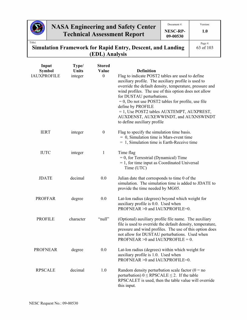
NASA Engineering and Safety Center Technical Assessment Report
Document #:
NESC-RP-09-00530
Version:
1.0
Title:
Simulation Framework for Rapid Entry, Descent, and Landing (EDL) Analysis
Page #:
63 of 103
NESC Request No.: 09-00530
Input Symbol
Type/ Units
Stored Value
Definition
IAUXPROFILE integer 0 Flag to indicate POST2 tables are used to define auxiliary profile. The auxiliary profile is used to override the default density, temperature, pressure and wind profiles. The use of this option does not allow for DUSTAU perturbations. = 0, Do not use POST2 tables for profile, use file define by PROFILE = 1, Use POST2 tables AUXTEMPT, AUXPREST, AUXDENST, AUXEWWINDT, and AUXNSWINDT to define auxiliary profile
IERT integer 0 Flag to specify the simulation time basis. = 0, Simulation time is Mars-event time = 1, Simulation time is Earth-Receive time
IUTC integer 1 Time flag = 0, for Terrestrial (Dynamical) Time = 1, for time input as Coordinated Universal Time (UTC)
JDATE decimal 0.0 Julian date that corresponds to time 0 of the simulation. The simulation time is added to JDATE to provide the time needed by MG05.
PROFFAR degree 0.0 Lat-lon radius (degrees) beyond which weight for auxiliary profile is 0.0. Used when PROFNEAR >0 and IAUXPROFILE=0.
PROFILE character “null” (Optional) auxiliary profile file name. The auxiliary file is used to override the default density, temperature, pressure and wind profiles. The use of this option does not allow for DUSTAU perturbations. Used when PROFNEAR >0 and IAUXPROFILE = 0.
PROFNEAR degree 0.0 Lat-lon radius (degrees) within which weight for auxiliary profile is 1.0. Used when PROFNEAR >0 and IAUXPROFILE=0.
RPSCALE decimal 1.0 Random density perturbation scale factor (0 = no perturbation) 0 ≤ RPSCALE ≤ 2. If the table RPSCALET is used, then the table value will override this input.

NASA Engineering and Safety Center Technical Assessment Report
Document #:
NESC-RP-09-00530
Version:
1.0
Title:
Simulation Framework for Rapid Entry, Descent, and Landing (EDL) Analysis
Page #:
64 of 103
NESC Request No.: 09-00530
5.5.5.1 Mars-GRAM
The POST2 inputs for the Mars-GRAM 2005 (MG05) model are given in Table 5.5.1.5 and the POST2 outputs are in Table 5.5.1.6.
Table 5.5.1.5. Additional POST2 Inputs for the Mars-GRAM Model Input
Symbol Type/ Units
Stored Value
Definition
NPC(5) integer 2 The atmosphere model selection flag. =11, MG2005 model
NPC(6) Integer 0 Wind calculation flag = 4, Use MG05 determination of North-South, East-West, and Vertical winds
ALSDUR degree 48.0 Duration (in Ls degrees) for dust storm
ALS0 degree 0.0 Starting Ls value (degrees) for dust storm (0 = none)
BLWINFAC decimal 0.0 Scale factor for boundary layer slope winds (0 = slope winds)
DELTATEX °K 0.0 Adjustment for exospheric temperature
DUSTDENS kg/m^3
3000 Dust particle density
DUSTDIAM micrometers
5.0 Dust particle diameter (assumed uniformly dispersed)
DUSTLAT degree 0.0 Latitude of center of dust storm. Used if ALS0 >0.
DUSTLON degree 0.0 Longitude of center of dust storm. Used if ALS0 >0.
DUSTMAX decimal 1.0 Maximum seasonal dust tau if DUSTTAU=0. Must be ≤ 1.0
DUSTMIN decimal 0.3 Minimum seasonal dust tau if DUSTTAU=0. Must be ≥0.1
DUSTNU decimal 0.003 Parameter for vertical distribution of dust density (Haberle et al., J. Geophys. Res., 104, 8957, 1999)

NASA Engineering and Safety Center Technical Assessment Report
Document #:
NESC-RP-09-00530
Version:
1.0
Title:
Simulation Framework for Rapid Entry, Descent, and Landing (EDL) Analysis
Page #:
65 of 103
NESC Request No.: 09-00530
Input Symbol
Type/ Units
Stored Value
Definition
DUSTTAU decimal 0.3 Visual optical depth of background dust level (no time-developing dust storm, just uniformly mixed dust), 0.1 to 3.0, or use 0 for assumed seasonal variation of background dust.
F107 solar flux units
68 Increment of solar activity at 1AU
GCMDIR character “null” The location of the Global Climate Model binary files. The default files are located in “/node/post_data/mg05_data”
HGTASFCM m 0.0 Used to simulate that the terrain is below the surface as determined by the MOLAHGTS option. This prevents the winds from being set to 0 and the temperature becoming invariant as MG05 determines that the input altitude is below the surface. 0 ≤ HGTASFCM ≤ 4500.0
IATMFL5 integer 0 Use external routines to calculate Local True Solar Time (corresponds to MG05 TLOCAL), and Local Mean Solar Time. = 0, Do not use external routines = 1, Use external routines
IBOUGHER integer 2 Height offset model for Bougher high altitude model. = 0, No Ls-dependent (Bougher) height offset term = 1, Add Ls-dependent (Bougher) term, -A*Sin(Ls)
(km), to constant term (zoffset) [offset amplitude A = 2.5 for MapYear=0 or 0.5 for
MapYear > 0] = 2, Use global mean height offset from data file
hgtoffst.dat (stored in “DATADIR” ) = 3, Use mean daily height offset at local position from data file hgtoffst.dat (stored in “DATADIR” ) =4, Use height offset at local position and time from data file hgtoffst.dat (stored in “DATADIR”)
INTENS integer 0 Dust storm intensity (0.0 - 3.0).

NASA Engineering and Safety Center Technical Assessment Report
Document #:
NESC-RP-09-00530
Version:
1.0
Title:
Simulation Framework for Rapid Entry, Descent, and Landing (EDL) Analysis
Page #:
66 of 103
NESC Request No.: 09-00530
Input Symbol
Type/ Units
Stored Value
Definition
IRES integer 16 MOLA resolution used if MOLAHGTS = 2. = 16, 1/16 degree resolution MOLA data = 32, 1/32 degree resolution MOLA data = 64, 1/64 degree resolution MOLA data = 128, 1/128 degree resolution MOLA data
IUWAVE integer 0 = 0, No time-dependent wave model
> 0, Unit number for (Optional) time-dependent wave coefficient data file "WaveFile". WaveFile contains time (seconds) relative to start time, and wave model coefficients (WaveA0 thru Wavephi3) from the given time to the next time in the data file.
LAT_NORTH decimal 999.0 Defines the northern boundary of the MOLA data to be loaded. Used if MOLAHGTS=2.
LAT_SOUTH decimal 999.0 Defines the southern boundary of the MOLA data to be loaded. Used if MOLAHGTS=2.
LON_EAST decimal 999.0 Defines the eastern boundary of the MOLA data to be loaded. Used if MOLAHGTS=2.
LON_WEST decimal 999.0 Defines the western boundary of the MOLA data to be loaded. Used if MOLAHGTS=2.
MAPYEAR integer 0 Flag to set which stored Mars mean atmosphere parameters are used. = 0, Mars-GRAM GCM input data sets = 1, TES mapping year 1 = 2, TES mapping year 2
MARSGAM decimal 1.29 Ratio of specific heats at Mars. Used to calculate speed of sound and d(Mach)/d(time).
MOLAHGTS integer 1 Altitude reference flag = 0, Use altitude relative to reference ellipsoid = 1, Use MG05 internal MOLA altitudes (0.5 degree resolution) = 2, Use MOLA reference defined by IRES.
PHI1DOT deg/day 0.0 Rate of longitude movement (degrees per day) for wave-1 component.

NASA Engineering and Safety Center Technical Assessment Report
Document #:
NESC-RP-09-00530
Version:
1.0
Title:
Simulation Framework for Rapid Entry, Descent, and Landing (EDL) Analysis
Page #:
67 of 103
NESC Request No.: 09-00530
Input Symbol
Type/ Units
Stored Value
Definition
PHI2DOT degree/day 0.0 Rate of longitude movement (degrees per day) for wave-2 component.
PHI3DOT degree/day 0.0 Rate of longitude movement (degrees per day) for wave-3 component.
RADMAX km
0.0 Maximum radius (km) of dust storm (0 or >10000 = global).
REQUA km (ft)
0.0 Equatorial radius of reference ellipsoid.
RPOLE km (ft)
0.0 Polar radius of reference ellipsoid.
RWSCALE decimal 1.0 Random wind perturbation scale factor (>=0). 0 is used to produce mean winds only.
STDL decimal 0.0 Standard deviation for thermosphere variation (-3.0 to +3.0).
WAVEA0 decimal 1.0 Mean term of longitude-dependent wave multiplier for density.
WAVEA1 decimal 0.0 Amplitude of wave-1 component of longitude-dependent wave multiplier for density.
WAVEA2 decimal 0.0 Amplitude of wave-2 component of longitude-dependent wave multiplier for density.
WAVEA3 decimal 0.0 Amplitude of wave-3 component of longitude-dependent wave multiplier for density.
WAVEDATE decimal 0.0 Julian date for (primary) peak(s) of wave (0 for no traveling component).
WAVEFILE character “null” (Optional) file for time-dependent wave coefficient data. See file description under parameter iuwave.
WAVEPHI1 degree 0.0 Phase of wave-1 component of longitude-dependent wave multiplier.

NASA Engineering and Safety Center Technical Assessment Report
Document #:
NESC-RP-09-00530
Version:
1.0
Title:
Simulation Framework for Rapid Entry, Descent, and Landing (EDL) Analysis
Page #:
68 of 103
NESC Request No.: 09-00530
Input Symbol
Type/ Units
Stored Value
Definition
WAVEPHI2 degree 0.0 Phase of wave-2 component of longitude-dependent wave multiplier.
WAVEPHI3 degree 0.0 Phase of wave-3 component of longitude-dependent wave multiplier.
WLSCALE decimal 1.0 Scale factor used to calculate density perturbations. Used to multiply density dispersions due to distance moved from previous point. Valid values are 0.1-10.
WMSCALE decimal 1.0 Scale factor for mean winds.
WSCALE km
20 Vertical scale (km) of longitude-dependent wave damping at altitudes below 100 km (10<=Wscale<=10,000 km). This prevents using WAVE0 as a constant multiplier below 100 km.
ZOFFSET km (ft)
5.0 Constant height offset (km) for Global Atmosphere Model data. Also constant part of Ls-dependent (ibougher=1). Height offset 0.0 means no constant offset. Positive offset increases density, and negative offset decreases density. Not used if IBOUGHER ≥2
Table 5.5.1.6. Additional POST2 Outputs for the Mars-GRAM Model Output Symbol
Type/ Units
Definition
COMOLE percent Percentage of carbon monoxide (CO) by volume in atmosphere.
CO2MOLE percent Percentage of CO2 by volume in atmosphere.
HEMOLE percent Percentage of helium (HE) by volume in atmosphere.
HMOLE percent Percentage of diatomic hydrogen (H) by volume in atmosphere.
H2MOLE percent Percentage of hydrogen (H2) by volume in atmosphere.
H20MOLE percent Percentage of water (H2O) vapor by volume in atmosphere.
LTST
hours Local true solar time calculated when IATMFL5 =1.

NASA Engineering and Safety Center Technical Assessment Report
Document #:
NESC-RP-09-00530
Version:
1.0
Title:
Simulation Framework for Rapid Entry, Descent, and Landing (EDL) Analysis
Page #:
69 of 103
NESC Request No.: 09-00530
Output Symbol
Type/ Units
Definition
LS deg Planetocentric longitude of the sun
OMOLE percent Percentage of oxygen (O2) by volume in atmosphere.
OWLT min One way light time.
O2MOLE percent Percentage of oxygenO2 by volume in atmosphere.
RPSCALE decimal RPSCALE value.
RWSCALE decimal RWSCALE value.
TLOCAL hours Local True Solar time.
WINDV ft/s (m/s)
Vertical wind velocity – used if NPC(6) =4.
5.5.5.2 Titan-GRAM
Other than the inputs and outputs as indicated above, the POST2 inputs for the Titan-GRAM (TGRAM) model are given in Table 5.5.1.7 and the POST2 outputs are in Table 5.5.1.8.
Table 5.5.1.7. Additional POST2 Inputs for the Titan-GRAM Model Input
Symbol Type/ Units
Stored Value
Definition
NPC(5) integer 10 The atmosphere model selection flag. =12, Titan-GRAM model
FMINMAX decimal 0.0 Specify the mean density profile to use between the Yelle minimum and the Yelle maximum. -1 corresponds to Yelle minimum, 0 to Yelle average and 1 to Yelle maximum. Used if IFMM =0
FMOLMETH percent 0.0 Specify the percentage of CH4 in atmosphere = 0 Use default Yelle methane mole fraction = 1-5, User defined percentage of methane fraction by volume in atmosphere

NASA Engineering and Safety Center Technical Assessment Report
Document #:
NESC-RP-09-00530
Version:
1.0
Title:
Simulation Framework for Rapid Entry, Descent, and Landing (EDL) Analysis
Page #:
70 of 103
NESC Request No.: 09-00530
Input Symbol
Type/ Units
Stored Value
Definition
IFMM
integer 1 Flag to specify the mean density profile. = 0, Use FMINMAX as input = 1, Calculate FMINMAX as a function of season, latitude and time of day. = 2, Use Hourdin GCM data input and Mueller- Wodarg exoatmospheric temperature model instead of FMINMAX envelope approach
TITANGAM decimal 1.47 Ratio of specific heats at Titan. Used to calculate speed of sound and d(Mach)/d(time)
Table 5.5.1.8. Additional POST2 Outputs for the Titan-GRAM Model Output Symbol
Type/ Units
Definition
CH4MOLE percent Percentage of CH4 by volume in atmosphere.
FMNMXOUT decimal FMINMAX used within TGRAM. Calculated if IFMM = 0 or 1
LS decimal Planetocentric longitude of the sun
OWLT min One way light time.
TLOCAL hours Local true solar time
5.5.5.3 Venus-GRAM
Other than the inputs and outputs as indicated above, the POST2 inputs for the Venus-GRAM (VGRAM) model are given in Table 5.5.1.9 and the POST2 outputs are in Table 5.5.1.10.

NASA Engineering and Safety Center Technical Assessment Report
Document #:
NESC-RP-09-00530
Version:
1.0
Title:
Simulation Framework for Rapid Entry, Descent, and Landing (EDL) Analysis
Page #:
71 of 103
NESC Request No.: 09-00530
Table 5.5.1.9. Additional POST2 Inputs for the Venus-GRAM Model Input
Symbol Type/ Units
Stored Value
Definition
NPC(5) integer 10 The atmosphere model selection flag. =13, Venus-GRAM model
FMINMAX decimal 0.0 Specify the mean density profile to use between the Yelle minimum and the Yelle maximum. -1 corresponds to Yelle minimum, 0 to Yelle average and 1 to Yelle maximum. Used if IFMM =0
FMOLMETH percent 0.0 Determination of methane mole fraction = 0, Use default Yelle methane mole fraction = 1-5, User defined percentage of CH4 fraction by volume in atmosphere
VENUSGAM decimal 1.45 Ratio of specific heats at Venus. Used to calculate speed of sound and d(Mach)/d(time)
Table 5.5.1.10. Additional POST2 Outputs for the Venus-GRAM Model Output Symbol
Type/ Units
Definition
COMOLE percent Percentage of CO by volume in atmosphere.
CO2MOLE percent Percentage of CO2 by volume in atmosphere.
HEMOLE percent Percentage of HE by volume in atmosphere.
HMOLE percent Percentage of H by volume in atmosphere.
LS decimal Planetocentric longitude of the sun
NMOLE percent Percentage of N by volume in atmosphere.
OMOLE percent Percentage of diatomic oxygen (O) by volume in atmosphere.
OWLT min One way light time.
TLOCAL hours Local true solar time

NASA Engineering and Safety Center Technical Assessment Report
Document #:
NESC-RP-09-00530
Version:
1.0
Title:
Simulation Framework for Rapid Entry, Descent, and Landing (EDL) Analysis
Page #:
72 of 103
NESC Request No.: 09-00530
5.5.5.4 Neptune-GRAM
Other than the inputs and outputs as indicated above, the POST2 inputs for the Neptune-GRAM (NGRAM) model are given in Table 5.5.1.11 and the POST2 outputs are in Table 5.5.1.12.
Table 5.5.1.11. Additional POST2 Inputs for the Neptune-GRAM Model Input
Symbol Type/ Units
Stored Value
Definition
NPC(5) integer 10 The atmosphere model selection flag. =14, Neptune-GRAM model
FMINMAX decimal 0.0 Specify the mean density profile to use between the Yelle minimum and the Yelle maximum. -1 corresponds to Yelle minimum, 0 to Yelle average and 1 to Yelle maximum. Used if IFMM =0
FMOLNITRO percent 0.0 User specified N2 mole fraction. Range is 0-0.6 percent = 0, Use default N2 mole fraction = 1-5, User define N2 mole fraction
IFMM
integer 1 Flag to specify the mean density profile. = 0, Use FMINMAX as input = 1, Calculate FMINMAX as a function of season, latitude and time of day. = 2, Use Hourdin GCM data input and Mueller- Wodarg exoatmospheric temperature model instead of FMINMAX envelope approach
NEPTUNEGAM decimal 1.45 Ratio of specific heats at Neptune. Used to calculate speed of sound and d(Mach)/d(time)

NASA Engineering and Safety Center Technical Assessment Report
Document #:
NESC-RP-09-00530
Version:
1.0
Title:
Simulation Framework for Rapid Entry, Descent, and Landing (EDL) Analysis
Page #:
73 of 103
NESC Request No.: 09-00530
Table 5.5.1.12. Additional POST2 Outputs for the Neptune-GRAM Model Output Symbol
Type/ Units
Definition
CH4MOLE percent Percentage of CH4 by volume in atmosphere.
FMNMXOUT decimal FMINMAX used within NGRAM. Calculated if IFMM = 0 or 1.
HEMOLE percent Percentage of HE by volume in atmosphere.
H2MOLE percent Percentage of H2 by volume in atmosphere.
LS decimal Planetocentric longitude of the sun
N2MOLE percent Percentage of N2 by volume in atmosphere.
OWLT min One way light time.
TLOCAL hours Local true solar time
5.5.5.5 Earth-GRAM
The POST2 inputs specific to the Earth-GRAM model are given in Table 5.5.1.13, and the POST2 outputs are in Table 5.5.1.14.
Table 5.5.1.13. POST2 Inputs for the Earth-GRAM Model Input
Symbol Type/ Units
Stored Value
Definition
NPC(5) integer 10 The atmosphere model selection flag. =10, Earth-GRAM model
AP decimal 0.0 Geomagnetic index
ATMPATH character “null” Path name for “atmosdat” atmospheric data file
F10 solar flux units
0.0 Daily 10.7-cm flux
F10b solar flux units
0.0 Mean 10.7-cm flux
GUAPATH character “null” Path name for GUACA files

NASA Engineering and Safety Center Technical Assessment Report
Document #:
NESC-RP-09-00530
Version:
1.0
Title:
Simulation Framework for Rapid Entry, Descent, and Landing (EDL) Analysis
Page #:
74 of 103
NESC Request No.: 09-00530
Input Symbol
Type/ Units
Stored Value
Definition
IATMFL1 integer 1 The GRAM initialization flag. For first vehicle number that uses GRAM =0, Do not initialize GRAM =1, Initialize GRAM Required for first call to GRAM
For other vehicles using GRAM = 0, Do not update initial random number – will
maintain same atmosphere density variability profile as another vehicle (correlated atmospheres)
= 1, Initialize atmosphere for new vehicle – no correlation between vehicle atmospheres
IATMFL2 integer 0 Random number seed – used when variable
atmosphere mode (IATMFL3=1) is used
IATMFL3 integer 0 Perturbed atmosphere property options = 0, Mean density, temperature, pressure and speed of sound.
= 1, Perturbed density, mean temperature and pressure, and perturbed speed of sound
IATMFL4 integer 0 Winds to use if NPC(6)=4 = 0, nominal GRAM winds = 1, nominal GRAM winds + perturbations
IAUXPROFILE integer 0 Flag to indicate POST2 tables are used to define auxiliary profile. The auxiliary profile is used to override the default density, temperature, pressure and wind profiles. The use of this option does not allow for DUSTAU perturbations. = 0, Do not use POST2 tables for profile, use file define by PROFILE = 1, Use POST2 tables AUXTEMPT, AUXPREST, AUXDENST, AUXEWWINDT, and AUXNSWINDT to define auxiliary profile
IDA integer 0 Day of the month

NASA Engineering and Safety Center Technical Assessment Report
Document #:
NESC-RP-09-00530
Version:
1.0
Title:
Simulation Framework for Rapid Entry, Descent, and Landing (EDL) Analysis
Page #:
75 of 103
NESC Request No.: 09-00530
Input Symbol
Type/ Units
Stored Value
Definition
IGUAYR integer 0 Determines which GUACA files are used. = 1 GUACA period of record = 2 Actual GUACA year (1985-1981), based on value of IYR
IHRO integer 0 Initial UTC (Greenwich) time hour
INITPERT integer 0 Initial perturbations flag = 0 GRAM-derived random initial perturbations values = 1 User-selected initial perturbations
ITHERM integer 0 Thermosphere model selection flag. = 1 MET (Jacchia) = 2 MSIS = 3 JB2006
IURRA integer 0 Unit number for Range Reference Atmosphere (RRA) data. = 0 none = xx actual unit number ( recommend 42)
IYR integer 0 4 digit or 2 digit year. If 2 digits are used IYR>56=19xx, IYR<57 =20xx
IYRRRA integer 0 Selects which group of RRA to use. = 1 1983 RRAs = 2 2006 RRAs
MINO integer 0 Initial UTC (Greenwich) time minute
MN integer 0 Month (1-12)
PATCHY integer 0 Patchiness in perturbation model. = 0 no patchiness ≠ 0 patchiness
PROFILE character “null” (Optional) auxiliary profile input file name. The auxiliary file is used to override the default density, temperature, pressure, and wind profiles.

NASA Engineering and Safety Center Technical Assessment Report
Document #:
NESC-RP-09-00530
Version:
1.0
Title:
Simulation Framework for Rapid Entry, Descent, and Landing (EDL) Analysis
Page #:
76 of 103
NESC Request No.: 09-00530
Input Symbol
Type/ Units
Stored Value
Definition
RDINIT percent 0.0 Initial density perturbation model (percent of mean). Used if INITPERT = 1
RPINIT percent 0.0 Initial pressure perturbation model (percent of mean). Used if INITPERT = 1
RPSCALE decimal 1.0 Random density perturbation scale factor (0 = no perturbation) 0 ≤ RPSCALE ≤ 2. If the table RPSCALET is used, the table value will override this input.
RRAPATH character “null” Directory for RRA data
RTINIT percent 0.0 Initial temperature perturbation model (percent of mean). Used if INITPERT = 1
RUINIT m/s 0.0 Initial eastward wind velocity perturbation model. Used if INITPERT = 1
RVINIT m/s 0.0 Initial northward wind velocity perturbation model. Used if INITPERT = 1
RWINIT m/s 0.0 Initial upward wind velocity perturbation model. Used if INITPERT = 1
SECO decimal 0.0 Initial UTC (Greenwich) time minute
SITELIM degree 0.0 Lat-Lon radius from RRA or PROFILE outside of which the RRA or PROFILE data are not used.
SITENEAR degree 0.0 Lat-Lon radius from RRA or PROFILE inside of which the RRA or PROFILE data are used with 1.0 weighting factor. Between SITENEAR and SITELIM the weighting factor transitions from 1.0 to 0.0 smoothly.
S10 decimal 0.0 EUV index (26-34 nm) scaled to F10 units (i.e., 0.0 corresponds to S10=F10).
S10B decimal 0.0 EUV 81-day center-averaged index scaled to F10B units (i.e., 0.0 corresponds to S10B=F10B).

NASA Engineering and Safety Center Technical Assessment Report
Document #:
NESC-RP-09-00530
Version:
1.0
Title:
Simulation Framework for Rapid Entry, Descent, and Landing (EDL) Analysis
Page #:
77 of 103
NESC Request No.: 09-00530
Input Symbol
Type/ Units
Stored Value
Definition
XM10 decimal 0.0 MG2 index scaled to F10 units (i.e., 0.0 corresponds to XM10=F10).
XM10B decimal 0.0 MG2 81-day center-average index scaled to F10 units (i.e., 0.0 corresponds to XM10B=F10).
Table 5.5.1.14. POST2 Outputs for the Earth-GRAM Model Output Symbol
Type/ Units
Definition
CH4MOLE percent Percentage of CH4 by volume in atmosphere.
COMOLE percent Percentage of CO by volume in atmosphere.
CO2MOLE percent Percentage of CO2 by volume in atmosphere.
DENS76STAND slug/ft3 (kg/m3)
1976 standard atmospheric density.
EWWINDMEAN ft/s (m/s)
Mean East/West wind velocity. Positive to the East.
HEMOLE percent Percentage of HE by volume in atmosphere.
HMOLE percent Percentage of H by volume in atmosphere.
H2OMOLE percent Percentage of H2O by volume in atmosphere.
NMOLE percent Percentage of N by volume in atmosphere.
N2OMOLE percent Percentage of nitrous oxide (N2O) by volume in atmosphere.
NSWINDMEAN ft/s (m/s)
Mean North/South wind velocity. Positive to the North.
OMOLE percent Percentage of O by volume in atmosphere.
O2MOLE percent Percentage of O2 by volume in atmosphere.
O3MOLE percent Percentage of ozone (O3) by volume in atmosphere.

NASA Engineering and Safety Center Technical Assessment Report
Document #:
NESC-RP-09-00530
Version:
1.0
Title:
Simulation Framework for Rapid Entry, Descent, and Landing (EDL) Analysis
Page #:
78 of 103
NESC Request No.: 09-00530
Output Symbol
Type/ Units
Definition
PRESMEAN lb/ft2 (N/m2)
Mean atmospheric pressure.
PRES76STAND lb/ft2 (N/m2)
1976 standard atmospheric pressure.
TEMPMEAN degree R (degree K)
Mean atmospheric temperature.
TEMP76STAND degree R (degree K)
1976 standard atmospheric temperature.
VERTWINDMEAN ft/s (m/s)
Mean vertical wind velocity. Positive down.
WINDV ft/s (m/s)
Vertical wind velocity. Positive down. Used if NPC(6) =4
5.5.5.6 Jupiter Table Atmosphere Model
The only Jupiter atmosphere incorporated into POST2 calculates the mean atmospheric parameters. The user provides tables of mean values of density, pressure and temperature, and the constituent number densities. Recommended values in a POST2 table format are available as an include file at /node/post_data/jupiter_data/jupiter.dat. POST2 inputs and outputs are shown in Tables 5.5.1.15 and 5.5.1.16, respectively.

NASA Engineering and Safety Center Technical Assessment Report
Document #:
NESC-RP-09-00530
Version:
1.0
Title:
Simulation Framework for Rapid Entry, Descent, and Landing (EDL) Analysis
Page #:
79 of 103
NESC Request No.: 09-00530
Table 5.5.1.15. POST2 Inputs for the Jupiter Atmosphere Model Input
Symbol Type/ Units
Stored Value
Definition
NPC(5) integer 10 The atmosphere model selection flag. =15, Jupiter atmosphere
JUPITERGAM decimal 1.4348 Ratio of specific heats at Jupiter. Used to calculate speed of sound.
Table 5.5.1.16. Additional POST2 Outputs for the Jupiter Atmosphere Model Output Symbol
Type/ Units
Definition
ATEM degree R (degree K)
Atmospheric temperature.
CH4MOLE percent Percentage of CH4 by volume in atmosphere.
CS ft/s (m/s)
Speed of sound.
DENS slug/ft3 (kg/m3)
Atmospheric density. DENS = DENS * GENTAB(DENKT)
HEMOLE percent Percentage of He by volume in atmosphere.
H2MOLE percent Percentage of H2 by volume in atmosphere. MOLWEIGHT decimal Molecular weight of atmosphere
PRES lb/ft2 (N/m2)
Atmospheric pressure.
ZHPRES km (ft)
Atmospheric pressure scale height.
ZHRHO km (ft)
Atmospheric density scale height.
5.5.5.7 Uranus Atmosphere Model
The only Uranus atmosphere incorporated into POST2 calculates the mean atmospheric parameters. The user provides tables of mean values of density, pressure and temperature, and

NASA Engineering and Safety Center Technical Assessment Report
Document #:
NESC-RP-09-00530
Version:
1.0
Title:
Simulation Framework for Rapid Entry, Descent, and Landing (EDL) Analysis
Page #:
80 of 103
NESC Request No.: 09-00530
the constituent number densities. Recommended values in a POST2 table format are available as an include file at /node/post_data/uranus_data/uranus.dat.
Table 5.5.1.17. POST2 Inputs for the Uranus Atmosphere Model Input
Symbol Type/ Units
Stored Value
Definition
NPC(5) integer 10 The atmosphere model selection flag. =16, Uranus atmosphere
URANUSGAM decimal 1.45 Ratio of specific heats at Uranus. Used to calculate speed of sound.
Table 5.5.1.18. Additional POST2 Outputs for the Uranus Atmosphere Model Output Symbol
Type/ Units
Definition
ATEM degree R (degree K)
Atmospheric temperature.
CH4MOLE percent Percentage of CH4 by volume in atmosphere.
CS ft/s (m/s)
Speed of sound.
DENS slug/ft3 (kg/m3)
Atmospheric density. DENS = DENS * GENTAB(DENKT)
HEMOLE percent Percentage of He by volume in atmosphere.
H2MOLE percent Percentage of H2 by volume in atmosphere.
MOLWEIGHT decimal Molecular weight of atmosphere
PRES lb/ft2 (N/m2)
Atmospheric pressure.
ZHPRES km (ft)
Atmospheric pressure scale height.

NASA Engineering and Safety Center Technical Assessment Report
Document #:
NESC-RP-09-00530
Version:
1.0
Title:
Simulation Framework for Rapid Entry, Descent, and Landing (EDL) Analysis
Page #:
81 of 103
NESC Request No.: 09-00530
Output Symbol
Type/ Units
Definition
ZHRHO km (ft)
Atmospheric density scale height.
5.5.5.8 Saturn Atmosphere Model
The only Saturn atmosphere incorporated into POST2 calculates the mean atmospheric parameters. The user provides tables of mean values of density, pressure and temperature, and the constituent number densities. Recommended values in a POST2 table format are available as an include file at /node/post_data/saturn_data/saturn.dat.
Table 5.5.1.19. POST2 Inputs for the Saturn Atmosphere Model Input
Symbol Type/ Units
Stored Value
Definition
NPC(5) integer 10 The atmosphere model selection flag. =17, Saturn atmosphere
SATURNGAM decimal 1.45 Ratio of specific heats at Saturn. Used to calculate speed of sound.
Table 5.5.1.20. POST2 Outputs for the Saturn Atmosphere Model Output Symbol
Type/ Units
Definition
ATEM degree R (degree K)
Atmospheric temperature.
CH4MOLE percent Percentage of CH4 by volume in atmosphere.
CS ft/s (m/s)
Speed of sound.
DENS slug/ft3 (kg/m3)
Atmospheric density. DENS = DENS * GENTAB(DENKT)
HEMOLE percent Percentage of He by volume in atmosphere.
H2MOLE percent Percentage of H2 by volume in atmosphere.

NASA Engineering and Safety Center Technical Assessment Report
Document #:
NESC-RP-09-00530
Version:
1.0
Title:
Simulation Framework for Rapid Entry, Descent, and Landing (EDL) Analysis
Page #:
82 of 103
NESC Request No.: 09-00530
Output Symbol
Type/ Units
Definition
MOLWEIGHT Decimal Molecular weight of atmosphere
PRES lb/ft2 (N/m2)
Atmospheric pressure.
ZHPRES km (ft)
Atmospheric pressure scale height.
ZHRHO km (ft)
Atmospheric density scale height.
5.5.5.9 Gravity Models for POST2
Spherical harmonic gravity field models for Mars (85x85), Venus (180x180), and the Earth’s moon (150x150) were obtained and put into a format for use with the current POST2 gravity model. Standard POST2 inputs and outputs for gravity models are used; the spherical harmonic gravity model is invoked in POST2 using NPC(16)=7 and the file containing the sectoral and tesseral data is identified in the input (including system directory path) using the POST2 variable GRAVDATA. References Environment Model
5.5.1 Duvall, A.L.; Justus, C.G.; and Keller, V.W.: ”Global Reference Atmospheric Model (GRAM) Series for Aeroassist Applications,” AIAA Paper 2005-1239, 43rd AIAA Aerospace Sciences Meeting and Exhibit, Reno, Nevada, 10-13 January 2005. 5.6 Scripts
The following scripts support the POST2 simulation used by the EDL-SA team. The list is categorized according to the function capability. Tools that are made up by a set of scripts are also included. All the scripts that have been identified were written in Matlab, PERL, and C-shell. The scripts are organized into seven function categories: animation object creation, file and scientific data conversion, plotting and label plots, POST2 processing, POST2 data management, scientific calculation, and kinematics. There are also five sets of script tools to help optimize the POST2 analysis capability. The following script tools are often used to generate POST2 output,

NASA Engineering and Safety Center Technical Assessment Report
Document #:
NESC-RP-09-00530
Version:
1.0
Title:
Simulation Framework for Rapid Entry, Descent, and Landing (EDL) Analysis
Page #:
83 of 103
NESC Request No.: 09-00530
animations, and plots: POST2 Trajectory Animation Tool, Monte Carlo PERL, Single POST2 Run, POST2 Test Suite, and Contour Tool.
5.6.1 Function Scripts
5.6.1.1 Animation Object Creation
There are two files that are used for creating animation object for trajectory analysis. These scripts do not have input and output parameters as shown in Table 5.6.1.1. Both files are located at /app/production/Scripts/Animation_Object_Creation.
Table 5.6.1.1. Animation Object Creation Scripts
5.6.1.2 File and Scientific Data Conversion
Three MATLAB scripts were used for file and scientific data conversion as indicated in Table 5.6.1.2. Both mat2ascci.m and mat2ascii_func.m are file conversion scripts that convert a MATLAB file to an ASCII file format (i.e., simple text file format). The mat2ascii.m lists the MATLAB files in the current directory and prompts the user to select the desired file to be converted from binary to ASCII format. The mat2ascii_func.m is a MATLAB function that takes a file name as a parameter and converts that file to an ASCII file with “.txt” file extension. The bplane2cartesian.m is a data conversion script that converts a planar coordinate system to Cartesian coordinate system. The scripts are located at: /app/production/Scripts/File_and_Scientific_Data_Conversion.
Table 5.6.1.2 File and Scientific Data Conversion Scripts
Script Name Function Description Input Parameter
mat2ascii.m To converts a .mat file to ASCII None
mat2ascii_func.m To convert filename.mat to filename.txt ASCII file Filename.mat
bplane2cartesian.m To Converts B-plane coordinate to Cartesian None
5.6.1.3 Plotting and Plot Labels
There are 43 MATLAB scripts shown in Table 5.6.1.3 that are used to customize plots and plot labels of POST2 output data. These scripts provide different types of plots to help visualize the POST2 results. To display more detailed information about the plot, users can customize and
Script Name Function Description
aeroshell.m To create areoshell shape for animation purposes.
axis3d.m To creates axis for animation.

NASA Engineering and Safety Center Technical Assessment Report
Document #:
NESC-RP-09-00530
Version:
1.0
Title:
Simulation Framework for Rapid Entry, Descent, and Landing (EDL) Analysis
Page #:
84 of 103
NESC Request No.: 09-00530
position the plotting legend to improve the information conveyed. The scripts are located at: /app/production/Scripts/Plotting_and_Plot_Labels.
Table 5.6.1.3 Plotting and Plot Label Scripts
Script Name Function Description Input Parameter Output Parameter
Add_events.m Draws vertical lines at all the events in a time history plot
fname : name of the POST output file
None
altimeter.m Draws barometric altimeter
Altitude None
AreoidDiff.m Read in MOLA areoid and plot difference to MG2001 or MER areoid
None None
bentext.m Inserts text into a plot str : text string to be put in plot str_x : x location of label from 0 to 1 str_y : y location of label from 0 to 1 fsize : font size
None
bpplot.m Generates a scatter plot in the B-plane. The points are enclosed by an ellipse of probability p.
x : B-dot-T y : B-dot-R p
None
check_states.m Plots monte carlo dispersed initial states to confirm correct error is being used
states,name,rei,mu None
ciplot.m Draws a circular intersection of a given input radius on a sphere of a given radius centered at input latitude and longitude.
None None
circle.m Return the latitude and longitude of points on a circle with radius circrad centered at lonref,latref, on a planet with radius planrad. circrad and planrad, have units of length. latref and lonref are in degrees.
latref, lonref, circrad, planetrad lat - latitude, lon - longitude

NASA Engineering and Safety Center Technical Assessment Report
Document #:
NESC-RP-09-00530
Version:
1.0
Title:
Simulation Framework for Rapid Entry, Descent, and Landing (EDL) Analysis
Page #:
85 of 103
NESC Request No.: 09-00530
Script Name Function Description Input Parameter Output Parameter
datestamp.m Puts current date in lower left corner of plot. Returns handle to axis and text.
None None
EllipsDiff.m Plots the difference between the MG2001 and MER areoid. User must input the resolution and specify the lat and long range for viewing. Required data files are in /planet2/ops/bin/atmos/Mola1_32/
None None
ellipse.m Return the latitude and longitude of points on an ellipse with major axis majaxis and minor axis minaxis centered at lonref,latref and oriented at azimuth on a planet with radius planrad. majaxis, minaxis and planrad have (the same) units of length. latref, lonref and azimuth are in degrees.
latref, lonref, planetrad, majaxis minaxis, azimuth
lat - latitude, lon - longitude
format_plot.m Plot formatting h,main_title,sub_title,footer_text,my_initials
None
format_subplot.m Formats an individual subplot axis according to settings found in get_format_settings.m
ax,plot_title,x_label,y_label,z_label None
format_subplotyy.m Formats an individual subplot axis according to settings found in get_format_settings.m
ax1,ax2,plot_title,x_label,y_label_1,y_label_2
None
get_format_settings.m
Plot formatting settings None None
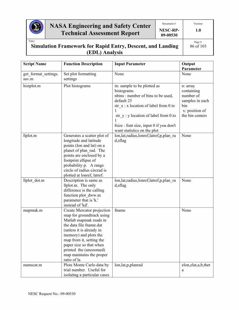
NASA Engineering and Safety Center Technical Assessment Report
Document #:
NESC-RP-09-00530
Version:
1.0
Title:
Simulation Framework for Rapid Entry, Descent, and Landing (EDL) Analysis
Page #:
86 of 103
NESC Request No.: 09-00530
Script Name Function Description Input Parameter Output Parameter
get_format_settings.sav.m
Set plot formatting settings
None None
histplot.m Plot histograms in: sample to be plotted as histograms nbins : number of bins to be used, default 25 str_x : x location of label from 0 to 1 str_y : y location of label from 0 to 1 fsize : font size, input 0 if you don't want statistics on the plot
n: array containing number of samples in each bin x: position of the bin centers
llplot.m Generates a scatter plot of longitude and latitude points (lon and lat) on a planet of plan_rad. The points are enclosed by a footprint ellipse of probability p. A range circle of radius circrad is plotted at lonref, latref.
lon,lat,radius,lonref,latref,p,plan_rad,sflag
None
llplot_dot.m Description is same as llplot.m. The only difference is the calling function plot_dww.m parameter that is 'k.' instead of 'kd'.
lon,lat,radius,lonref,latref,p,plan_rad,sflag
None
mapmak.m Create Mercator projection map for groundtrack using Matlab mapmak reads in the data file fname.dat (unless it is already in memory) and plots the map from it, setting the paper size so that when printed the (unzoomed) map maintains the proper ratio of la
fname None
numscat.m Plots Monte Carlo data by trial number. Useful for isolating a particular cases
lon,lat,p,planrad elon,elat,a,b,theta

NASA Engineering and Safety Center Technical Assessment Report
Document #:
NESC-RP-09-00530
Version:
1.0
Title:
Simulation Framework for Rapid Entry, Descent, and Landing (EDL) Analysis
Page #:
87 of 103
NESC Request No.: 09-00530
Script Name Function Description Input Parameter Output Parameter
out of the Monte Carlo
numscatmcp2.m Plots Monte Carlo by using index. Useful for isolating a particular cases out of the Monte Carlo
xvec,yvec,indx,xname,yname,figno hx, hy
plot_dww.m Linear plot. varargin None
plot_hist_subp1.m Plots one histogram n : plot number n1: index of 1st variable being plotted nbins : number of bins str_x : x location for the summary string str_y : y location for the summary string fsize : font size for the summary string pflag : print flag, 1:PC format, 2:MAC form
None
plot_hist_subp3.m Plots 3 histograms on one plot
n: plot number n1: index of 1st variable being plotted n2: index of 2nd variable being plotted n3: index of 3rd variable being plotted nbins : number of bins str_x : x location for the summary string str_y : y location for the summary s
None
plot_hist_subp3_special.m
Special case of plot_hist_subp3()
n : plot number n1: index of 1st variable being plotted n2: index of 2nd variable being plotted n3: index of 3rd variable being plotted nbins : number of bins str_x : x location for the summary string str_y : y location for the summary
None

NASA Engineering and Safety Center Technical Assessment Report
Document #:
NESC-RP-09-00530
Version:
1.0
Title:
Simulation Framework for Rapid Entry, Descent, and Landing (EDL) Analysis
Page #:
88 of 103
NESC Request No.: 09-00530
Script Name Function Description Input Parameter Output Parameter
str
plot_hist_subp4.m Plots 4 histograms on one plot
n: plot number n1: index of 1st variable being plotted n2: index of 2nd variable being plotted n3 : index of 3rd variable being plotted n4 : index of 4th variable being plotted nbins : number of bins str_x : x location for the summary s
None
plot_output.m Script makes histograms of all monte-carlo variables, needs matout and output_var
matout: output from the monte carlo run output_var: text description of the variables plot_flag: flag to turn on plotting, defaults to zero save_plots_flag : flag t
output_variables_text : statistics of all the variables in tabular format
plot_rwp.m Plots vector Y versus vector X.
Varargin None
plot3_dww.m Plot lines and points in 3D space.
Varargin Column vector of handles to LINE objects.
range_circle.m Plots and labels a circle of radius circ_rad centered at longitude lonref and latitude latref on a planet of radius plan_rad. Circ_rad and plan_rad have the same units.
radius, lonref, latref, plan_rad None
range_circle_rwp.m Plots and labels a circle of radius circ_rad centered at longitude lonref and latitude latref on a planet of radius plan_rad. Circ_rad and plan_rad have the same units.
radius, lonref, latref, plan_rad None

NASA Engineering and Safety Center Technical Assessment Report
Document #:
NESC-RP-09-00530
Version:
1.0
Title:
Simulation Framework for Rapid Entry, Descent, and Landing (EDL) Analysis
Page #:
89 of 103
NESC Request No.: 09-00530
Script Name Function Description Input Parameter Output Parameter
stairs_dww.m Draws a stairstep graph of the elements
x and y None
subtitle.m Centers two titles over a group of subplots. Returns a handle to the title and the handle to an axis.
None ax = returns hundles to both the axis and the title.
text_dww.m Adds the text in the string to location (X,Y) on the current axes.
x,y,string None
textbox.m Places text in a subplot at position=[xpos,ypos].
mytext, xpos, ypos, vert_align, horiz_align
None
textemq.m Allows placement of text in a plot using normalized units.
None x,y,string
title2.m Places a [possible multi-line] title above the plot
str: string matrix or array of lines None
underscore_4plot.m Adds a \ before every underscore returns resulting string
str_in: string in str_out : string out
weibplot.m Displays a Weibull probability plot of the percent data in X
H: handle to the plotted lines. None
weifit.m Plots a histogram of values in the vector DATA using NBINS bars in the histogram.
h(1) - a handle to the histogram H(2) - a handle to the density curve
None
wrapper.m Plots latitude, longitude pairs, lifting pen if the track wraps around longitude 180 degree.
longit, latit, color None
xxxpagenum.m Puts initials and integer (usually page number) in lower right corner of plot separated by '-'.
function [ax,h] None

NASA Engineering and Safety Center Technical Assessment Report
Document #:
NESC-RP-09-00530
Version:
1.0
Title:
Simulation Framework for Rapid Entry, Descent, and Landing (EDL) Analysis
Page #:
90 of 103
NESC Request No.: 09-00530
5.6.1.4 POST2 Post-Processing
The MATLAB scripts listed in Table 5.6.1.4 are used for POST2 processing. As indicated in the table, users can post-process POST2 data to get visual comparisons, statistical information, and for general data query. The files are located at: /app/production/Scripts/POST2_Processing.
Table 5.6.1.4. POST2 Post-Processing Scripts
Scripts Name Function Descriptions Input Parameter Output Parameter
attitude_movie.m Visually compares actual to commanded attitude
yaw, pit, rol, yawc, pitc, rolc, ntimes None
auto_stats.m Places statistical data into a vector format
data None
center.m Calculates the expected error (value - mean) of input data
x y
changle.m Creates yaw, pitch, and roll from input Direction Cosine Matrix. Useful to visualize the spacecraft attitude
lb1, lb2, lb3, lb4, lb5, lb6, lb7, lb8, lb9 ea1,ea2,ea3
chkdis.m Compares data from two separate runs
in1, in2 None
chkdisplt.m Same as chkdis.m except it plots the difference
in1, in2 None
chkmat1.m Compares data from two separate runs
in1, in2 None
get_event_index.m Obtains the event numbers and times from the POST output
event: event structure containing event times fname: name of the POST output file
event_out : event structure which contains time also
get_event_times.m Prints the event times in .out file
fname_out : name of the POST2 output file
None
get_events.m Obtains the event numbers and times from the POST output deck
fname: name of the POST output file event : structure which stores the event data
sens.m Evaluates sensitivities from Monte Carlo run, does pseudo inverse to find which input variable contribute most to output variables.
matout.mat, random_inputs.dat None

NASA Engineering and Safety Center Technical Assessment Report
Document #:
NESC-RP-09-00530
Version:
1.0
Title:
Simulation Framework for Rapid Entry, Descent, and Landing (EDL) Analysis
Page #:
91 of 103
NESC Request No.: 09-00530
5.6.1.5 POST2 Data Management
There are four MATLAB scripts that are used for POST2 data management displayed in Table 5.6.1.5. These scripts are useful to quickly create one and two dimensional POST2 tables, add an extension to multiple variables in a MATLAB workspace, and converts POST2 input to MATLAB readable file. The files are located at: /app/production/Scripts/POST2_Data_Management.
Table 5.6.1.5. POST2 Data Management Scripts
Script Name Function Description Input Parameter Output Parameter
add_ext.m Adds extension to all variables in workspace. Either define 'extension' locally or input extension when prompted.
None None
freederb.m Reads files written by table2 or table2a. table2 converts POST input files to a form that MATLAB can read.
None None
tabPOST2.m Writes 1 dimensional POST2 table
tabnam: string of table name tablab: string of table label indepv: independent variable vector depv: dependent variable vector interptype: string of interpolation type (lin_inp,log_inp,step_inp,spline_inp) extraptype: string of extrapolation ty
A file called [tnam '.dat'] with a POST table in it.
tabPOST22d.m Writes 2 dimensional POST2 table
ivarnam1 = string of independent variable 1 nam ivarnam2 = string of independent variable 2 name tabnam = string of table name tablab = string of table label indepv1 = independent variable 1 vector (ni1x1) indepv2 = independent variable 2 vector (ni2x1
A file called [tnam '.dat'] with a POST table in it.
5.6.1.6 Scientific Calculations
There are 53 MATLAB scripts that are scientific calculations used for POST2 analysis. Table 5.6.1.6 indicates the different functions of these scripts, such as geometry calculations, spatial orientation, conversions from any frame of reference, transformation between direction cosine matrix (DCM) and Euler’s angles, calculation of dispersion ellipse, rotation matrix, and other

NASA Engineering and Safety Center Technical Assessment Report
Document #:
NESC-RP-09-00530
Version:
1.0
Title:
Simulation Framework for Rapid Entry, Descent, and Landing (EDL) Analysis
Page #:
92 of 103
NESC Request No.: 09-00530
useful calculations for POST2 analysis purposes. The files are located at: /app/production/Scripts/Scientific_Calculations.
Table 5.6.1.6. Scientific Calculation Scripts Script Name Function Description Input Parameter Output Parameter
acosd.m Returns arc cosine in degrees : [b] = acosd(a)
a : cosine of the angle b : angle (degrees)
angle_between.m Calculates the angle between two vectors
v1 : 1st vector v2 : 2nd vector
angle : angle between the two vectors
angle360.m Calculates the angle between A and B, ccw with respect to 'up' vector
A : 1st vector B : 2nd vector up : vector with respect to which the direction is calculated
angle : angle between the two vectors (degree)
asind.m Returns arc sine in degrees
a: sin of the angle b : angle (degrees)
atan2d.m Returns arc tangent in degrees
x : x part of arctan(y/x) y : y part of arctan(y/x)
a : angle (degrees)
atand.m Returns arc tangent in degrees
x : tangent of the angle a : angle (degrees)
cosd.m Returns cos a : angle whose cosine is being calculated (degrees)
b : sine of a
cross.m Takes the cross product a,b : 3x1 vectors c : 3x1 vector
dcmtoea132.m Converts direction cosine matrix to 1-3-2 Euler Angles
None ea132 = [ 1st rot; 2nd rot; 3rd rot] ea132(1) = angle about the 1-axis ea132(2) = angle about the 3-axis ea132(3) = angle about the 2-axis
dcmtoea231.m Converts direction cosine matrix to 2-3-1 Euler Angles
None ea231 = [ 1st rot; 2nd rot; 3rd rot] ea231(1) = angle about the 2-axis ea231(2) = angle about the 3-axis ea231(3) = angle about the 1-axis
dcmtoea313.m Converts direction cosine matrix to 3-1-3 Euler Angles
None None

NASA Engineering and Safety Center Technical Assessment Report
Document #:
NESC-RP-09-00530
Version:
1.0
Title:
Simulation Framework for Rapid Entry, Descent, and Landing (EDL) Analysis
Page #:
93 of 103
NESC Request No.: 09-00530
Script Name Function Description Input Parameter Output Parameter
dcmtoea321.m Converts direction cosine matrix to 3-2-1 Euler Angles
None None
dcmtoev.m Calculates Euler rotation and vector from direction cosine matrix
alpha evec
dispersion_ellipse.m Calculates the dispersion ellipse
lat_deg : latitude vector of the points (degree) lon_deg : longitude vector of the points (degree) Radius : planet radius (any desired unit) adjust_angle : rotation angle of the ellipse to adjust orientation, default zero (degree) prcnt_change : percent ch
ellipse_lat: ellipse latitude vector (degree) ellipse_lon: ellipse longitude vector (degree) semimajor_dr: 3 sigma dispersion in downrange, semimajor (same unit as Radius) semiminor_dr: 3 sigma dispersion in crossrange, semiminor (same unit as Radius) pseudo_azimuth: azimuth for the resultant ellipse (degree). This routine will only return azimuth angles from 0 to 180. Beware when using this routine for incoming bodies with azimuth angles outside this range. The quadrant of the azimuth may need to be adjusted.
DRx.m Returns rotation matrix for rotation about the x axis
a : rotation angle (degrees) R : rotation matrix (3x3)
DRy.m Returns rotation matrix for rotation about the y axis
a : rotation angle (degrees) R : rotation matrix (3x3)
DRz.m Returns rotation matrix for rotation about the z axis
a : rotation angle (degrees) R : rotation matrix (3x3)
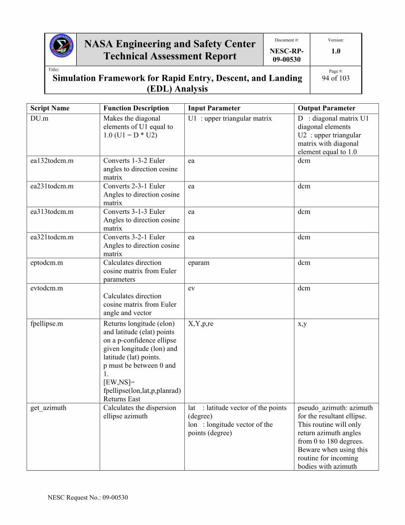
NASA Engineering and Safety Center Technical Assessment Report
Document #:
NESC-RP-09-00530
Version:
1.0
Title:
Simulation Framework for Rapid Entry, Descent, and Landing (EDL) Analysis
Page #:
94 of 103
NESC Request No.: 09-00530
Script Name Function Description Input Parameter Output Parameter
DU.m Makes the diagonal elements of U1 equal to 1.0 (U1 = D * U2)
U1 : upper triangular matrix D : diagonal matrix U1 diagonal elements U2 : upper triangular matrix with diagonal element equal to 1.0
ea132todcm.m Converts 1-3-2 Euler angles to direction cosine matrix
ea dcm
ea231todcm.m Converts 2-3-1 Euler Angles to direction cosine matrix
ea dcm
ea313todcm.m Converts 3-1-3 Euler Angles to direction cosine matrix
ea dcm
ea321todcm.m Converts 3-2-1 Euler Angles to direction cosine matrix
ea dcm
eptodcm.m Calculates direction cosine matrix from Euler parameters
eparam dcm
evtodcm.m Calculates direction cosine matrix from Euler angle and vector
ev dcm
fpellipse.m Returns longitude (elon) and latitude (elat) points on a p-confidence ellipse given longitude (lon) and latitude (lat) points. p must be between 0 and 1. [EW,NS]= fpellipse(lon,lat,p,planrad)Returns East
X,Y,p,re x,y
get_azimuth Calculates the dispersion ellipse azimuth
lat : latitude vector of the points (degree) lon : longitude vector of the points (degree)
pseudo_azimuth: azimuth for the resultant ellipse. This routine will only return azimuth angles from 0 to 180 degrees. Beware when using this routine for incoming bodies with azimuth

NASA Engineering and Safety Center Technical Assessment Report
Document #:
NESC-RP-09-00530
Version:
1.0
Title:
Simulation Framework for Rapid Entry, Descent, and Landing (EDL) Analysis
Page #:
95 of 103
NESC Request No.: 09-00530
Script Name Function Description Input Parameter Output Parameter
angles outside this range (retrograde orbits). The quadrant of the azimuth may need to be adjusted.
get_azimuth_1point.m Calculates the dispersion ellipse azimuth
lat_ref: latitude of the reference points (degree) lon_ref: longitude of the reference points (degree) lat: latitude of the point in question (degree) lon: longitude of the point in question (degree)
azimuth : azimuth on the point in question with respect to the reference point
getGeodetic.m Returns gdlat, long, gdalt given XYZ
v : vector of vehicle position, vector(3) a : planet equatorial radius b : planet polar radius
gdlat: gedetic latitude long: longitude gdalt: geodetic altitude
helipad4.m Find landing site based on MOLA topography. Searches MOLA database for sites with given altitude that are "flat" to within given tolerance across a circle of given radius. Optionally finds sites with hazards nearby, but outside landing area.
res: string containing data resolution (i.e., 1/2, 1/4, 1/8, 1/16, or 1/32) lat1: 1x1 Northern most latitude (degree) lat2: 1x1 Southern most latitude (degree) long1: 1x1 Minimum East longitude (degree) long2: 1x1 Maximum East longitude (degree) crad: radius of helipad, km targelev = target elevation, km elvtol: tolerance on target, km. center of pad must be within this of targelev padtol: tolerance on surrounding pad, km. all of pad must be within this of targelev rimhite: crater rim height, km. some point between crad and orad must be at least this much higher than targelev orad: radius outside of pad where crater wall must be km.
mxlat: nx1 latitudes for matrix of Mola data mxlong = mx1 longitudes for matrix of Mola data matrix = mxn matrix of MOLA data in desired lat and long region.

NASA Engineering and Safety Center Technical Assessment Report
Document #:
NESC-RP-09-00530
Version:
1.0
Title:
Simulation Framework for Rapid Entry, Descent, and Landing (EDL) Analysis
Page #:
96 of 103
NESC Request No.: 09-00530
Script Name Function Description Input Parameter Output Parameter
juldat.m Calculate Julian calendar date from Gregorian calendar date
caldat xjd
lookup1.m Linear interpolation table lookup
inputv,outputv,inval outval
molarad.m Approximate MOLA reference radius
gclat: geocentric latitude in degrees
planetrad = approximate MOLA reference radius in km
polyadd.m Adds two polynomials of different sizes
p1: 1st polynomial 1xn matrix p2: 2nd polynomial 1xm matrix
p3: polynomial with dimensions that match the degree of the higher degree polynomial
prctile.m Gives the percentiles of the sample in X.
x & p :percent None
qconj.m Form the conjugate, or inverse of a quaternion.
qAB Quaternion (Euler parameters) relating unit vectors ai to bi (i = 1,2,3). qBA: The conjugate of qAB, formed by changing the sign of the Euler vector used to form qAB.
None
qmult.m Calculate the quaternion which results from two successive rotations. Quaternion qAB relates reference frame A to B, qBC relates frame B to C, and qAC relates frame A to C.
qAB: Quaternion (Euler parameters) relating a dextral, mutually orthogonal set of unit vectors ai fixed in a reference frame A to a similar set of unit vectors bi fixed in B (i = 1,2,3).
None
qto321.m Calculate yaw, pitch, and roll angles describing the orientation of the core body B relative to directions fixed in a reference frame A.
qAB: Quaternion (Euler parameters) relating a dextral, mutually orthogonal set of unit vectors ai fixed in a reference frame A to a similar set of unit vectors bi fixed in B (i = 1,2,3).
None
qtoc.m Construct direction cosine matrix elements from quaternion.
qAB: Quaternion (Euler parameters) relating a dextral, mutually orthogonal set of unit vectors ai fixed in a reference frame A to a similar set of unit vectors bi fixed in B (i = 1,2,3).
None

NASA Engineering and Safety Center Technical Assessment Report
Document #:
NESC-RP-09-00530
Version:
1.0
Title:
Simulation Framework for Rapid Entry, Descent, and Landing (EDL) Analysis
Page #:
97 of 103
NESC Request No.: 09-00530
Script Name Function Description Input Parameter Output Parameter
rangegv.m Finds distance between 2 points on a planet and heading angle from one to the other. Calculates planet radius at both points and calculates distance along arc of sphere with average radius.
xlatrefg = latitude of reference point (degree) xlonrefg = longitude of reference point (degree) xlat = latitude of second point (degree) (may be column vector) xlon = longitude of second point (degree) (may be column vector) re,rp = equatorial and polar radii of pl
azim = azimuth from reference point to second point (degree) range = distance between points in units of radii
rangegv_mars.m Finds distance between 2 points on a planet and heading angle from one to the other. Calculates planet radius at both points and calculates distance along arc of sphere with average radius. Defaults to Mars-specific values.
xlatrefg = latitude of reference point (degree) xlonrefg = longitude of reference point (degree) xlat = latitude of second point (degree) (may be column vector) xlon = longitude of second point (degree) (may be column vector) re,rp = equatorial and polar radii
azim = azimuth from reference point to second point (degree) range = distance between points in units of radii
Rx.m Returns rotation matrix for rotation about the x axis
a: rotation angle (radians) R : rotation matrix (3x3)
Ry.m Returns rotation matrix for rotation about the y axis
a: rotation angle (radians) r: rotation matrix (3x3)
Rz.m Returns rotation matrix for rotation about the z axis
a: rotation angle (radians) R : rotation matrix (3x3)
sind.m Returns sin, angle input in degrees
a - angle whose cosine is being calculated
b: sine of a
size_ellipse.m Determines the size and orientation of a footprint ellipse given lat & lon.
lon , lat, planet radius, semi major axis, semi-minor axis, azimuth of semi-major axis
None
skew.m Puts 3x1 vector into 3x3 skew symmetric form
None None
stdci.m Returns the confidence interval for the standard deviation
x - vector or n - size p - confidence

NASA Engineering and Safety Center Technical Assessment Report
Document #:
NESC-RP-09-00530
Version:
1.0
Title:
Simulation Framework for Rapid Entry, Descent, and Landing (EDL) Analysis
Page #:
98 of 103
NESC Request No.: 09-00530
Script Name Function Description Input Parameter Output Parameter
tand.m Calculate and return tangent
a: angle whose cosine is being calculated
b: tangent of a
xkr.m Gaussian random number generator
iseed y: random number
5.6.1.7 Cartesian Conversion Script
The MATLAB script in Table 5.6.1.7 is used when the state is in Cartesian coordinates. It is used to generate the velocity magnitude and flight path angle, both inertial and planet relative, from the Cartesian state. The file is located at: /app/production/Scripts/Kinematics.
Table 5.6.1.7. Cartesian Conversion Script
Script Name
Function Description Input Parameter Output Parameter
convert.m Convert from Cartesian position and velocity to vmag and gamrrv
vmci - velocity in mci coordinates pmci - position in mci wie - rotation rate of planet
vrmag - magnitude of relative velocity gamrrv - flight path angle based on velr (degree) vmag - magnitude of inertial velocity gami - flight path angle based on veli (degree)
5.6.2 Tool Set Scripts
5.6.2.1 POST2 Trajectory Animation Tool
The POST2 Trajectory Animation Tool is a MATLAB based tool that transforms POST2 two-dimensional time history plots into a movie for analysis. This tool can help the user gain better knowledge of the dynamic behavior of a single body and multiple flight vehicles. An extensive explanation with step by step instructions to use this tool is given in Appendix C. This tool also has a graphic user interface (GUI) that integrates specific components of the animation tool to significantly reduce the time to generate the animation. The method and installation instructions are provided in Appendix D.
5.6.2.2 Monte Carlo PERL
The Monte Carlo PERL is a tool that generates multiple POST2 inputs to be run on the Linux cluster for parallel processing. The driver PERL script, qusb_mpi_nqueue.pl, shown in Table 5.6.1.8, takes the user specified submission parameters and runs a POST2 executable on any available Linux cluster. It also generates the necessary files such as a Portable Batch System

NASA Engineering and Safety Center Technical Assessment Report
Document #:
NESC-RP-09-00530
Version:
1.0
Title:
Simulation Framework for Rapid Entry, Descent, and Landing (EDL) Analysis
Page #:
99 of 103
NESC Request No.: 09-00530
(PBS) submission script and Message Passing Interface (MPI) PERL scripts by using template files to prepare and execute a job on the Linux cluster. A User’s Guide is provided in Appendix E.
Table 5.6.1.8. Monte Carlo PERL Script Script Name Function Description Template Files qsub_mpi_nqueue.pl To generate PERL and PBS scripts to run
POST2 inputs cases on the Linux clusters qtemplate.tpl and p2_qsub.pl
5.6.2.3 Single POST2 Run
The Single POST2 Run script tool provides flexibility for the engineer to run different versions of the POST2 executable on the Linux cluster. The driver script generates other PERL scripts by using the template file indicated in Table 5.6.1.9. A User’s Guide is in Appendix E.
Table 5.6.1.9. Single POST2 Run Script Script Name Function Description Template Files run_s_post.pl To generate PERL scripts and submit a
single job to the Linux cluster s_post.tpl
5.6.2.4 POST2 Test Suite
The validation of any POST2 source code additions and changes is essential. The POST2 Test Suite is a tool that compares the production versions to the new version of a POST2 executable. This tool generates a set of default POST2 production version outputs and then uses them to compare against the new POST2 outputs. The runtestsuite.pl PERL script in Table 5.6.1.10 is the driver that sets up both production and new output. The C-shell script called mace runs the comparison of the profiles and generates a summary of the findings. A user’s guide is in Appendix E.
Table 5.6.1.10. POST2 Test Suite Scripts
Script Name Function Description Template Files runtestsuite.pl To generate PERL, PBS, and c-shell
scripts to run POST2 test cases on the Linux cluster
go_n_tpl, tqsub_p2_tpl.pbs, and tq_p2_tpl.pl
mace To compare the old and new POST2 runs
profcomp, rcompare_8, and rcompare_9
5.6.2.5 POST2 Terrain Contour Plotting Tool
The POST2 Terrain Contour Plotting Tool is useful for landing site assessment. This tool plots the contour of terrain elevation for the Martian surface. It can also be used for Earth, Earth’s moon, Venus, and other planets by setting the path for the surface of the planet of interest in the

NASA Engineering and Safety Center Technical Assessment Report
Document #:
NESC-RP-09-00530
Version:
1.0
Title:
Simulation Framework for Rapid Entry, Descent, and Landing (EDL) Analysis
Page #:
100 of 103
NESC Request No.: 09-00530
user input file. This script is a subset of POST2 terrain library. There are two C programming files in Table 5.6.1.11 that are needed to compiled with the MATLAB compiler on a 32-bit machine to generate the MATLAB binary function file called getnground.mexglx. The contour plot can be generated by using the driver script make_plots.m inside MATLAB. The files are located at: /app/production/Scripts/POST2_Terrain_Contour_Plotting_Tool.
Table 5.6.1.11. POST2 Terrain Contour Plotting Script
Script Name Function Description
Dependent Files C programming Files
Compiled File
make_plots.m Generates contour plot using MATLAB
llplot.m, nc_contour_diff.m, print_plots.m, circle_dww.m, format_plot.m, format_subplot.m, Geod2Geoc.m
Getncground.c, ground.c
Getncground.mexglx
6.0 Observation and NESC Recommendation The following Observation and NESC Recommendation relate to technical aspects of the project and are directed to the NASA Technical Fellows for Flight Mechanics and GN&C:
O-1. A navigation filter model is needed to not only prepare for potential NESC tasks, but also to increase the fidelity of the EDL-SA assessments. While using perfect navigation (i.e., perfect knowledge of the true state) with guidance systems is a reasonable first step, errors from imperfect state knowledge helps determine the robustness of the guidance and vehicle design.
R-1. Include a navigation filter model as part of Phase 2 plan of this assessment. The filter should be consistent with those being developed for current CxP landing systems (i.e., Altair and ALHAT). (O-1)
7.0 Other Deliverables As part of the Phase 1 assessment, a plan for a Phase 2 assessment will be generated. This proposal involves additional models not included in Phase 1, such as a navigation filter similar to that being developed for CxP and making aerodynamic uncertainties an internal part of the aerodynamic models rather than user input.

NASA Engineering and Safety Center Technical Assessment Report
Document #:
NESC-RP-09-00530
Version:
1.0
Title:
Simulation Framework for Rapid Entry, Descent, and Landing (EDL) Analysis
Page #:
101 of 103
NESC Request No.: 09-00530
8.0 Definition of Terms Corrective Actions Changes to design processes, work instructions, workmanship practices,
training, inspections, tests, procedures, specifications, drawings, tools, equipment, facilities, resources, or material that result in preventing, minimizing, or limiting the potential for recurrence of a problem.
Finding A conclusion based on facts established by the investigating authority. Lessons Learned Knowledge or understanding gained by experience. The experience may
be positive, as in a successful test or mission, or negative, as in a mishap or failure. A lesson must be significant in that it has real or assumed impact on operations; valid in that it is factually and technically correct; and applicable in that it identifies a specific design, process, or decision that reduces or limits the potential for failures and mishaps, or reinforces a positive result.
Observation A factor, event, or circumstance identified during the assessment that did
not contribute to the problem, but if left uncorrected has the potential to cause a mishap, injury, or increase the severity should a mishap occur. Alternatively, an observation could be a positive acknowledgement of a Center/Program/Project/Organization’s operational structure, tools, and/or support provided.
Problem The subject of the independent technical assessment. Proximate Cause The event(s) that occurred, including any condition(s) that existed
immediately before the undesired outcome, directly resulted in its occurrence and, if eliminated or modified, would have prevented the undesired outcome.
Recommendation An action identified by the NESC to correct a root cause or deficiency
identified during the investigation. The recommendations may be used by the responsible Center/Program/Project/Organization in the preparation of a corrective action plan.
Root Cause One of multiple factors (events, conditions, or organizational factors) that
contributed to or created the proximate cause and subsequent undesired outcome and, if eliminated or modified, would have prevented the undesired outcome. Typically, multiple root causes contribute to an undesired outcome.

NASA Engineering and Safety Center Technical Assessment Report
Document #:
NESC-RP-09-00530
Version:
1.0
Title:
Simulation Framework for Rapid Entry, Descent, and Landing (EDL) Analysis
Page #:
102 of 103
NESC Request No.: 09-00530
9.0 Acronyms List AETD Applied Engineering & Technology Directorate AFE Aeroassist Flight Experiment AIAA American Institute of Aeronautics and Astronautics, Inc. AMA Analytical Mechanics Associates, Inc. AOA Angle-Of-Attack ARC Ames Research Center BPC Bank Angle Pseudo-Controller CAP CEV Aerosciences Project CBAERO Configuration Based Aerodynamics CEV Crew Exploration Vehicle CFD Computational Fluid Dynamics cg Center of Gravity CH4 Methane CO2 carbon dioxide CxP Constellation Program DoF Degree of Freedom DPLR Data Parallel Line Relaxation DRA Design Reference Architecture EDL Entry, Descent, and Landing GN&C Guidance, Navigation, and Control GRAM Global Random Atmosphere Model GSFC Goddard Space Flight Center HIAD Hypersonic Inflatable Aerodynamic Decelerator HQ Headquarters HYPAS Hybrid Predictor-Corrector Aerocapture Scheme Kn Knudsen number L/D Lift/Drag LaRC Langley Research Center LOX Liquid Oxygen LREF Ellipsled Reference Length m/CDS Vehicle Ballistic Coefficient MER Mars Exploration Rover MIAS Mars Inflatable Aeroshell System MSL Mars Science Laboratory nd non-dimensional NEQAIR Nonequilibrium Air Radiation NESC NASA Engineering and Safety Center

NASA Engineering and Safety Center Technical Assessment Report
Document #:
NESC-RP-09-00530
Version:
1.0
Title:
Simulation Framework for Rapid Entry, Descent, and Landing (EDL) Analysis
Page #:
103 of 103
NESC Request No.: 09-00530
NRB NESC Review Board OML outer mold line PCI Planet-Centered Inertial PCPF Planet-Centered Planet-Fixed PDR Preliminary Design Review POST2 Program to Optimize Simulated Trajectories II RCS Reaction Control System REDLAS Rapid EDL Analysis Simulation SE&I Systems Engineering and Integration TDT Technical Discipline Team TPS Thermal Protection System V Velocity Vector Volume II: Appendices (stand-alone volume) Appendix A. Gravity Turn Guidance Theoretical Development Appendix B. POST2 Mass Model Users’ Guide Appendix C. Animation Tool v2.3 Appendix D. Animation GUI v1.0 Appendix E. POST2 Scripts Users’ Guide