Soft Timers: Efficient Microsecond Software Timer Support for ...

TIMERS

Definitions
• A counter counts (possibly asynchronous) input pulses from an external signal
• A timer counts pulses of a fixed, known frequency usually the system clock for the processor

• Physically, timer is a register whose value is continually increasing to 255, and then it starts all over again: 0, 1, 2, 3, 4...255....0,1, 2, 3......etc.

• This incrementing is done in the background of everything a microcontroller does.
• It is up to programmer to think up a way how he will take advantage of this characteristic for his needs.
• One of the ways is increasing some variable on each timer overflow. – If we know how much time a timer needs to make one
complete round, then multiplying the value of a variable by that time will yield the total amount of elapsed time.
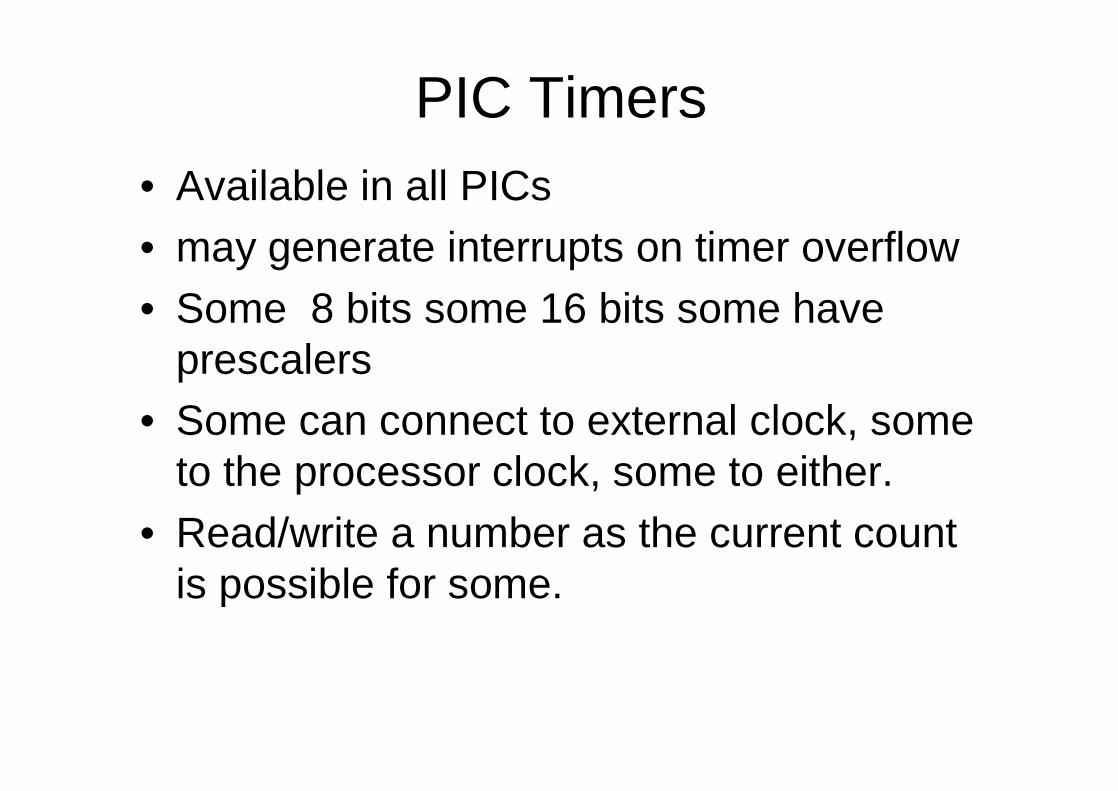
PIC Timers• Available in all PICs• may generate interrupts on timer overflow• Some 8 bits some 16 bits some have
prescalers• Some can connect to external clock, some
to the processor clock, some to either.• Read/write a number as the current count
is possible for some.

PIC Timers
• Can use external pin as clock in / clock out (i.e. for counting events)
• Warning: Some Peripherals shares timer resources.

PIC Timers
• The device has three readable and writeable hardware timers that can increment automatically each instruction cycle (if no prescaler is used).
• All timers can cause an interrupt on overflow, and then restart from zero.
PIC Timers
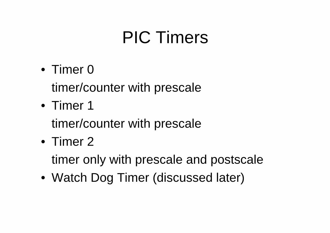
• Timer 0timer/counter with prescale
• Timer 1timer/counter with prescale
• Timer 2timer only with prescale and postscale
• Watch Dog Timer (discussed later)

Timers
• TIMER0 is an 8-bit timer with an eight bit prescaler, which can make the timer run 2 to 256 times slower than normal
• TIMER1 is a 16-bit timer (two 8-bit registers) with a 1:1 to 1:8 prescaler and some other features. Used by given C code to generate soft timer and sound
• TIMER2 is an 8-bit timer with 1:1 to 1:16 prescalerand a 1:1 to 1:16 postscaler It also has a period register.Used by given C code for PWM motor control

Timer 0
• 8 bit timer/counter with prescaler• Readable and writeable• 8-bit software programmable prescaler• Internal or external clock set• Interrupt on overflow from 0xFF to 0x00• Edge Select for external clock

Prescaler• Prescaler is a name for the part of a
microcontroller which divides oscillator clock before it will reach logic that increases timer status.
• Number which divides a clock is defined through first three bits in OPTION register.
• The highest divisor is 256. This actually means that only at every 256th clock, timer value would increase by one.
• This provides us with the ability to measure longer timer periods.


PreScaler
÷2 ÷2 ÷2 ÷2 ÷2 ÷2 ÷2 ÷2f f/2 f/4 f/8 f/16 f/32 f/64 f/128 f/256
8 input to 1 output multiplexerSelects one of the inputs to connect to output
Prescaler output
PS2, PS1, PS0 : PreScaler select inputs:Binary number on these 3 bits determine which input (0..7) to be selected
Note: if prescaler is disabled, input (f) is directly connected to the counter
Input 0 Input 7
Input clock withfrequency: f

• After each count up to 255, timer resets its value to zero and starts with a new cycle of counting to 255.
• During each transition from 255 to zero, T0IF bit in INTCON register is set. – If interrupts are allowed to occur, this can be taken
advantage of in generating interrupts and in processing interrupt routine.
– It is up to programmer to reset T0IF bit in interrupt routine, so that new interrupt, or new overflow could be detected.


• Beside the internal oscillator clock, timer status can also be increased by the external clock on RA4/TOCKI pin. – Choosing one of these two options is done in
OPTION register through T0CS bit. – If this option of external clock was selected, it
would be possible to define the edge of a signal (rising or falling), on which timer would increase its value.

Example• In practice, one of the typical example that is solved via external
clock and a timer is counting full turns of an axis of some production machine, like transformer winder for instance.
• Let's wind four metal screws on the axis of a winder. These fourscrews will represent metal convexity.
• Let's place now the inductive sensor at a distance of 5mm from the head of a screw.
• Inductive sensor will generate the falling signal every time the head of the screw is parallel with sensor head.
• Each signal will represent one fourth of a full turn, and the sum of all full turns will be found in TMR0 timer.
• Program can easily read this data from the timer through a data bus.


how to initialize timer to signal falling edges from external clock source with a prescaler

• Prescaler can be assigned either timer TMR0 or a watchdog. – Watchdog is a mechanism which microcontroller uses to defend
itself against programs getting stuck. • Prescaler is accorded to timer TMR0, or to watchdog
timer trough PSA bit in OPTION register. – By clearing PSA bit, prescaler will be accorded to timer TMR0.
When prescaler is accorded to timer TMR0, all instructions of writing to TMR0 register (CLRF TMR0, MOVWF TMR0, BSF TMR0,...) will clear prescaler.
– Prescaler change is completely under programmer's control, and can be changed while program is running.


• The timer is controlled by a number of bits in the Option Register.

Option Register• The option register is used to control a number
of processor features. • The least significant six bits of the option register
control the timer logic.• The OPTION_REG register is a readable and
writable register which contains various control bits to configure – the TMR0/WDT prescaler, – the External INT Interrupt, – TMR0, and – the weak pull-ups on PORTB.


PIC Timers / Timer 1
• 16-bit timer/counter with prescaler• Readable and writeable• 1, 2, 4, 8 programmable prescaler• Internal or external clock select• External clock can be syn. or asyn.• Interrupt on overflow• Second crystal permitted

PIC Timers / Timer 2
• 8-bit timer/counter with prescaler and postscaler
• Readable and writeable• 1,4 or 16 programmable prescaler• 4-bit programmable postscaler• Interrupt on overflow• Output to port pin

Selecting Parameters• In order to set up the timer, it is necessary to first decide
the time interval needed.• The basic timer rate is one microsecond (with a 4 MHz
crystal). • This one microsecond clock is divided by the prescaler,
which can be set to divide by 2, 4, 8, 16, 32, 64, 128 or 256.
• The timer register itself has 8 bits, so it can count to 256.• Thus, it is necessary to service the timer with software at
least every 256*256 microseconds, or 65.536 microseconds (assuming a 4 MHz clock).

Setting up the Timer
• To set up the timer, one must first disable interrupts so that an interrupt doesn’toccur when the timer expires.
• Then, enable the timer and assign the prescaler to the timer.
• Establish the prescaler value, and finally, load the timer register.
Setting up the Timer
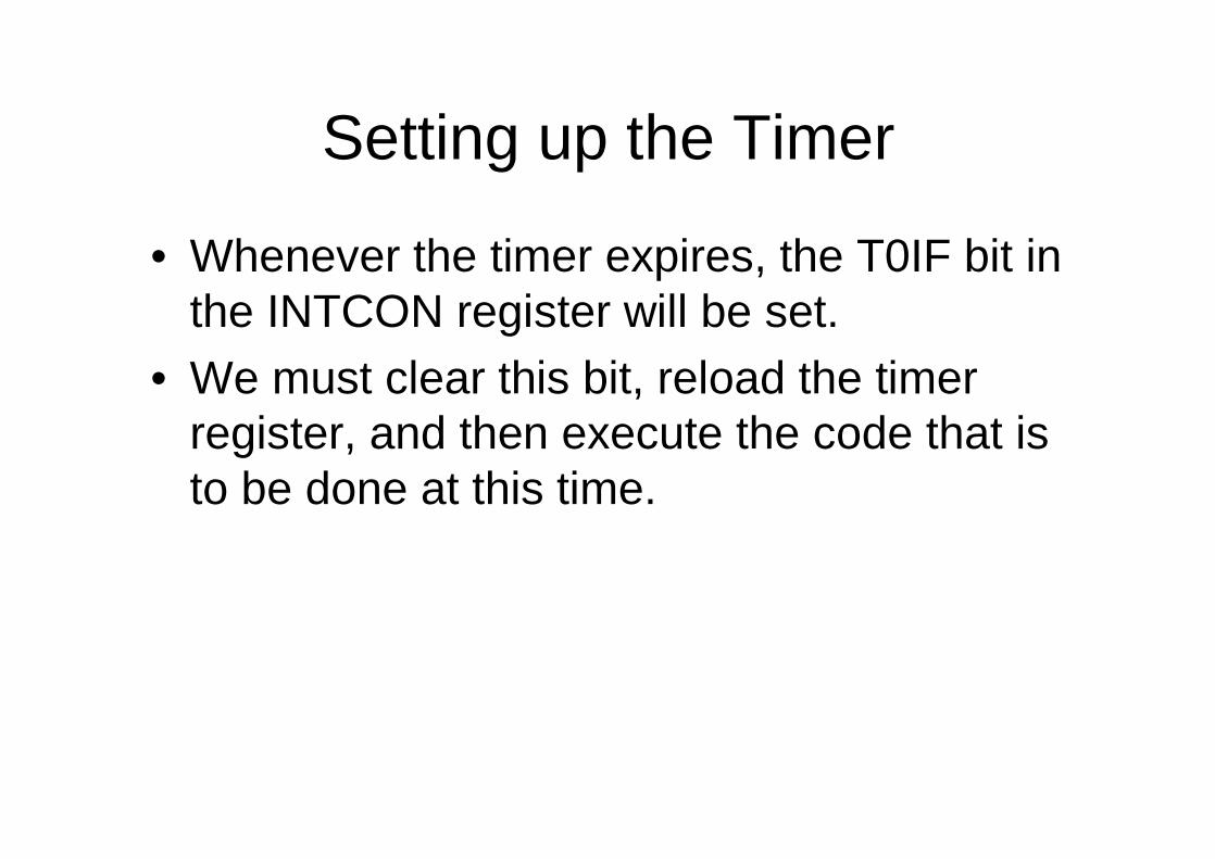
• Whenever the timer expires, the T0IF bit in the INTCON register will be set.
• We must clear this bit, reload the timer register, and then execute the code that is to be done at this time.


• In code, the setup portion might look something like:
banksel INTCONbcf INTCON,T0IE ; Mask timer interruptbanksel OPTION_REGbcf OPTION_REG,T0CS ; Enable timerbcf OPTION_REG,PSA ; Prescaler to timerbcf OPTION_REG,PS2 ; \bsf OPTION_REG,PS1 ; >- 1:16 prescalebsf OPTION_REG,PS0 ; /movlw D’100’ ; Timer will countmovwf TMR0 ; 156 (256-100) counts
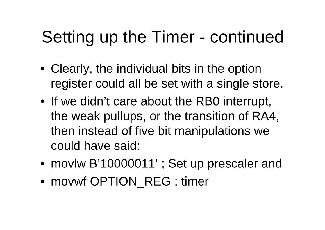
Setting up the Timer - continued
• Clearly, the individual bits in the option register could all be set with a single store.
• If we didn’t care about the RB0 interrupt, the weak pullups, or the transition of RA4,then instead of five bit manipulations we could have said:
• movlw B’10000011’ ; Set up prescaler and• movwf OPTION_REG ; timer

• The execution loop might look something like:
mainbtfss INTCON,T0IF ; Did timer overflow?goto main ; No, hang around some moremovlw D’100’ ; Timer will countmovwf TMR0 ; 156 (256-100) countsbcf INTCON,T0IF ; reset overflow flagcall DoCode ; Execute main codegoto main ; Go back and wait
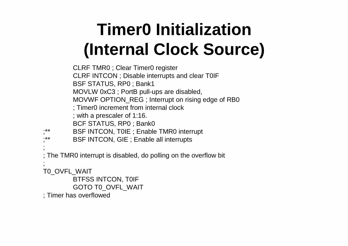
Timer0 Initialization (Internal Clock Source)
CLRF TMR0 ; Clear Timer0 registerCLRF INTCON ; Disable interrupts and clear T0IFBSF STATUS, RP0 ; Bank1MOVLW 0xC3 ; PortB pull-ups are disabled,MOVWF OPTION_REG ; Interrupt on rising edge of RB0; Timer0 increment from internal clock; with a prescaler of 1:16.BCF STATUS, RP0 ; Bank0
;** BSF INTCON, T0IE ; Enable TMR0 interrupt;** BSF INTCON, GIE ; Enable all interrupts;; The TMR0 interrupt is disabled, do polling on the overflow bit;T0_OVFL_WAIT
BTFSS INTCON, T0IFGOTO T0_OVFL_WAIT
; Timer has overflowed