Time over/undervoltage relay and protection assemblies RXEDK 2H ...
18
Page 1 Features • Micro-processor based time-over/under- voltage relay with continuous settings for start and time functions • Three variants, with wide setting ranges in two measuring stages: - Stage 1: U1 = (0,5-1,0) x U s - Stage 2: U2 = (0,25-1,5) x U s - U s = (0,2-1,6) x U r • The two measuring stages are switchable for over- or undervoltage function indepen- dently of each other • Stage 1 is programmable for two time characteristics: - Inverse time - Definite time delay settable 50 ms-16,1 s • Stage 2 can be delayed up to 10 s • Reset ratio typical 96% for overvoltage unction and 104% for undervoltage func- tion enables a setting close to maximum service values • Available with optional filters for different frequency characteristics: - 50-60 Hz, Sharp - 150-180 Hz, Sharp - 16 2/3 Hz, Flat (SE970120) (SE970114) Time over/undervoltage relay and protection assemblies RXEDK 2H and RAEDK 1MRK 509 004-BEN Issued January 2004 Revision: A Data subject to change without notice
Transcript of Time over/undervoltage relay and protection assemblies RXEDK 2H ...

Page 1
(SE970120)(SE970114)
Time over/undervoltage relay and protection assemblies
RXEDK 2H andRAEDK
1MRK 509 004-BEN
Issued January 2004Revision: A
Data subject to change without notice
Features • Micro-processor based time-over/under-voltage relay with continuous settings for start and time functions
• Three variants, with wide setting ranges in two measuring stages:
- Stage 1: U1 = (0,5-1,0) x Us
- Stage 2: U2 = (0,25-1,5) x Us
- Us = (0,2-1,6) x Ur
• The two measuring stages are switchable for over- or undervoltage function indepen-dently of each other
• Stage 1 is programmable for two timecharacteristics:
- Inverse time
- Definite time delay settable 50 ms-16,1 s
• Stage 2 can be delayed up to 10 s
• Reset ratio typical 96% for overvoltage unction and 104% for undervoltage func-tion enables a setting close to maximum service values
• Available with optional filters for different frequency characteristics:
- 50-60 Hz, Sharp
- 150-180 Hz, Sharp
- 16 2/3 Hz, Flat

Time over/undervoltage relay and protection assemblies
RXEDK 2H andRAEDK
1MRK 509 004-BENPage 2
Application RXEDK 2H is a time-over/undervoltage relay with two measuring stages, which are switchable for over- or undervoltage func-tions independently of each other. Stage 1 is programmable for the following two different time functions:
- Definite-time characteristic – where the operate time is independent of the volt-age deviation. The definite-time is set-table from 50 ms to 16,1 s.
- Inverse time characteristic – where the operate time is dependent of the voltage deviation from the set value (see Fig. 1). The relationship between time and volt-age for this characteristic can be expressed as follows:
Overvoltage function:standard
16 2/3 Hz alternative version
Undervoltage function:standard
16 2/3 Hz alternative version
wherek = inverse time constantU1 = over/undervoltage start valueU = operate value
Time characteristics is independent to the set-table value. The delay time is settable between 50 ms and 16,1 s.
Stage 2 has a definite-time characteristic, and is settable from 30 ms to 10 s.
The time-over/undervoltage relays of type RXEDK 2H can be used in a number of dif-ferent applications such as:
Neutral point voltage protectionTime delayed single-phase relay is used to detect occurrence of an earth fault in a net-work by detecting neutral point voltage on an open delta winding of phase transformers or on a neutral transformer. The start step can be used to release selective earth fault current protection.
Fig. 1 Inverse time characteristic.
Overvoltage protectionFor generator protection an overvoltage relay is used to detect failure in voltage regulation. For transformers and transmission lines, overvoltage protection is sometimes used to detect excessive voltages. For these applica-tions the high reset ratio is essential.
Flash-over protectionFor transformer low voltage windings an instantaneous protection will detect the high overvoltages occurring at a flash-over from the high to low voltage side of transformers where the low voltage side is not solidly earthed.
Undervoltage protectionAn undervoltage protection is used to discon-nect motors at low system voltage to prevent problems with inrush at system voltage recovery. Single-phase versions connected phase-phase are used for asynchronous motors, whereas measuring of positive sequence voltage is used for synchronous motors.
Stator earth fault protectionWith optimal filters for measuring either fun-damental overvoltage or third harmonic undervoltage.
tk
UU1-------- 1–----------------- s[ ]=
t kUU1------- 0 5,
1– -----------------------------------=
tk
1 UU1--------–
----------------- s[ ]=
tk
1 UU1------- 0 5,
– -----------------------------------=
U/U1
0,10 1
Time(s)
1
100
1000
k=16
k=2
k=0,5
k=5
2
k=16
k=2
k=0,5
k=510
(96000260)

Time over/undervoltage relay and protection assemblies
RXEDK 2H andRAEDK
1MRK 509 004-BENPage 3
Design The voltage relay assemblies with RXEDK 2H can be delivered in several variants for single- and three-phase over- or undervoltage protection with different output circuits.
All assemblies are with test switch RTXP 18, for simple secondary testing, and with trip indication either with LED or flag relay.
The RXEDK 2H relay requires a separate dc-dc converter for auxiliary supply (±24 V). One RXTUG converter can supply up to nine relays.
Note:When RXEDK 2H relay or the dc-dc con-verter RXTUG is plugged into or withdrawn from a terminal base, the auxiliary voltage supply must be interrupted. Neither is it allowed to open wiring on plus or minus sup-ply with unit in service.
RXEDK 2H measuring relayThe over/undervoltage relay, type RXEDK 2H, is a static microprocessor based relay with two delayed stages. The relay consists mainly of an input voltage transformer, filter circuits, microprocessor, HMI, LEDs for start and trip indications and three output units which provide separate change-over contacts for start and trip of stage 1, and trip of stage 2. The relay has also one binary input for reset LED.
Operate values for both stage 1 and 2, are set with the potentiometers and programming switches marked with Us. Both measuring stages can independently be programmed for over- or undervoltage functions. Operation occurs for a voltage equal to or larger/lower than the product of set scale value and the selected scale constant.
The start function output is energized imme-diately after the measured value exceeds or falls below the set start voltage level.
Stage 1 can be set for definite-time or inverse-time delay, while stage 2 only has definite time delay.
For definite-time delayed operation the time voltage output operates after the set time delay.
For inverse-time operation, the operate time will depend on the time setting (constant k + setting of programming switches), and by how much the measured voltage magnitude exceeds or falls below the start voltage level setting (see Fig. 1 for operation characteris-tic).
The relay can be supplied with optional filters for sharp measuring of fundamental frequen-cies (50-60 Hz) or third harmonics (150-180 Hz). The characteristics of the filters are shown in Fig. 2.

Time over/undervoltage relay and protection assemblies
RXEDK 2H andRAEDK
1MRK 509 004-BENPage 4
Technical dataTable 1: Voltage input
Rated voltage Ur 2/5 V or 20/50 V or 100/200 V, For 16 2/3 Hz: 2/5 V or 20/50 V,For 16 2/3 Hz: alternative version 20/50 V
Scale constant Us, (0,2-1,6) x Ur (in steps of 0,2)
Setting rangesStage U1
2/5 V 20/50 V100/200 V
Stage U22/5 V20/50 V100/200 V
0,2-3,2 V/0,5-8 V2-32 V/5-80 V10-160 V/20-320 V
0,1-4,8 V/0,25-12V1-48 V/2,5-120 V5-240 V/10-480 V
Effective voltage range U (0,25-2,0) x Us
Rated frequency fr
Frequency range
50-60 HzFilter opt.: 50-60 Hz, flat std (see Fig. 2)50-60 Hz, sharp (see Fig. 3)150-180 Hz, sharp (see Fig. 4)40-1000 Hz
16 2/3Hz
(see Fig. 5)
15-150 Hz
Power consumptionU = lowest UsU = highest Us
2 mVA210 mVA
Overload capacitycontinuouslyduring 10 s
3,5 x Ur (Max. 500 V AC for COMBIFLEX)4,0 x Ur (Max. 500 V AC for COMBIFLEX)
Table 2: Start and trip functions for standard, 50 Hz sharp and 150-180 Hz sharp
Voltage function Stage U1 Stage U2
Scale range (0,5-1,0) x Us (0,25-1,5) x Us
Measuring mode Over/Under voltage
Operate timeOver-voltage (typical)
U = 0 => 1,1 x op. valueU = 0 => 1,5 x op. valueU = 0,9 => 1,1 x op. valueU = 0,9 => 1,5 x op. valueU = 0,9 => 2,0 x op. value
Under-voltage (typical)U = 1,1 => 0,9 x op. valueU = 1,1 => 0,5 x op. valueU = 1,1 => 0 x op. value
Start function
45 ms40 ms35 ms30 ms25 ms
35 ms30 ms25 ms
t = 0,03 s
45 ms40 ms35 ms30 ms25 ms
35 ms30 ms25 ms
Reset time, Over-voltage (typical)U = 1,5 => 0,9 x op. valueU = 1,5 => 0 x op. value
Start function35 ms45 ms
t = 0,03 s35 ms45 ms
Consistency of the operate value < 0,5%
Reset ratio over/under > 95% / <105%
Recovery time < 50 ms
Overshoot time < 25 ms

Time over/undervoltage relay and protection assemblies
RXEDK 2H andRAEDK
1MRK 509 004-BENPage 5
Frequency dependence within frequency range 50 Hz, ±5%frequency range 60 Hz, ±5%
< 0,5%< 1,0%
Operate value at 150 Hz App. 1,45 x op. value at 50 Hz
Influence of harmonics100 / 120 Hz, 5%150 / 180 Hz, 20%250 / 300 Hz, 20%
< 2%< 6%< 3%
Table 3: Time functions for standard, 50 Hz sharp and 150-180 Hz sharp
Time function Stage U1 Stage U2
Time delay Definite time and inverse time Definite time
Setting rangeDefinite time, Def. timeInverse time, Inv
Formula for inverse timeOvervoltage functionUndervoltage function
t = 0,05-16,1 sk = 0,05-16,1
t = k / (a - 1)t = k / (1 - a)k = Inverse time factora = Over / under-voltage times
operate value
0,03-10 s–
AccuracyDefinite timeInverse time
Consistency
1% and ±10 ms1% of the over/under-voltage and ±10 ms or 3% of the oper-ate time and ±30 ms< 0,5%
1% and ±10 ms–
< 0,5%
Table 4: Filter option, deviation from technical data for RXEDK 2H, standard
Filter options
50-60 Hz, sharp 150-180 Hz, sharp
Operate time for start functionover-voltage (typical)
U = 0 => 1,1 x op. valueU = 0 => 1,5 x op. value
90 ms70 ms
65 ms50 ms
Reset ratio for over-voltage > 95%
Recovery time < 50 ms < 50 ms
Overshoot time < 35 ms < 30 ms
Frequency dependence within frequency range ±5% < 15% < 15%
Influence of harmonics50, 60 Hz, 100%100, 120 Hz, 100%150, 180 Hz, 100%250, 300 Hz, 100%
–< 3%< 3%< 1%
< 1%< 2%–< 2%
Table 2: Start and trip functions for standard, 50 Hz sharp and 150-180 Hz sharp
Voltage function Stage U1 Stage U2

Time over/undervoltage relay and protection assemblies
RXEDK 2H andRAEDK
1MRK 509 004-BENPage 6
Technical data (cont’d)Technical data (cont’d)Table 5: Start and trip functions 16 2/3 Hz
Voltage function Stage U1 Stage U2
Scale range (0,5-1,0) x Us (0,25-1,5) x Us
Measuring mode Over/Under voltage
Operate timeOver-voltage (typical)
U = 0,9 => 1,1 x op. valueU = 0,9 => 1,5 x op. valueU = 0,9 => 2,0 x op. value
Under-voltage (typical)U = 1,1 => 0,9 x op. valueU = 1,1 => 0,5 x op. valueU = 1,1 => 0 x op. value
Start function
75 ms55 ms50 ms
75 ms55 ms50 ms
t = 0,08 s
75 ms55 ms50 ms
75 ms55 ms50 ms
Reset time, Over-voltage (typical)U = 1,1 => 0,9 x op. valueU = 1,1 => 0,5 x op. valueU = 1,1 => 0 x op. value
Start function85 ms60 ms50 ms
t = 0,08 s85 ms60 ms50 ms
Consistency of the op. value < 1,0%
Reset ratio Over/Under > 95% / < 105%
Recovery time over-voltageU = 1,1 => 0 x op. valueU = 2,0 => 0 x op. value
< 60 ms< 90 ms
Overshoot time < 60 ms
Frequency dependence withinfrequency range 15,00-18,33 Hz < 2,0%
Influence of harmonics33 1/3 Hz, 5%50 Hz, 20%83 1/3 Hz, 20%
< 2%< 5%< 3%
Table 6: Time functions 16 2/3 Hz
Time function Stage U1 Stage U2
Time delay Definite time and inverse time Definite time
Setting range Definite time, Def. timeInverse time, Inv
Formula for inverse timeOvervoltage functionUndervoltage function
t = 0,05-16,1 sk = 0,05-16,1
t = k / (a - 1) *) t = k / (a0,5 - 1)t = k / (1 - a) *) t = k / (1 - a0,5)k = Inverse time factora = Over / under-voltage times
operate value*) 16 2/3 Hz alternative version
0,08-10 s–
AccuracyDefinite timeInverse time
Consistency
1% and ±30 ms1% of the over/under-voltage and ±30 ms or 3% of the operate time and ±60 ms< 0,5%
1% and ±30 ms–
< 0,5%

Time over/undervoltage relay and protection assemblies
RXEDK 2H andRAEDK
1MRK 509 004-BENPage 7
Table 7: Auxiliary DC voltage supply
Auxiliary voltage EL for RXTUG 22HAuxiliary voltage to the relay
24-250 V DC, ±20%±24 V (from RXTUG 22H)
Power consumption at RXTUG 22H input24-250 V
before operationafter operation
without RXTUG 22H±24 V
before operationafter operation
Standard
Max. 4,5 WMax. 6,0 W
Max. 1,3 WMax. 3,0 W
Other filters
Max. 5,5 WMax. 6,5 W
Max. 2,0 WMax. 3,0 W
Table 8: Binary input
Binary input voltage RL 48-60 V and 110-220 V DC, -20% to +10%
Power consumption48-60 V110-220 V
Max. 0,3 WMax. 1,5 W
Table 9: Output relays
Contacts 3 change-over
Maximum system voltage 250 V AC / DC.
Current carrying capacitycontinuousduring 1 s
5 A15 A
Making capacity at inductive load with L/R >10 msduring 200 msduring 1 s
30 A10 A
Breaking capacityAC, max. 250 V, cos ϕ > 0,4DC, with L/R < 40 ms
48 V110 V220 V250 V
8 A
1 A0,4 A0,2 A0,15 A
Table 10: Electromagnetic compatibility (EMC), immunity tests
All tests are done together with the DC/DC-converter, RXTUG 22H
Test Severity Standard
Surge 1 and 2 kV, normal service2 and 4 kV, destructive test
IEC 61000-4-5, class 3IEC 61000-4-5, class 4
AC injection 500 V, AC SS 436 15 03, PL 4
Power frequency magnetic field 1000 A/m IEC 61000-4-8
1 MHz burst 2,5 kV IEC 60255-22-1, class 3
Spark 4-8 kV SS 436 15 03, PL 4
Fast transient 4 kV IEC 60255-22-4, class 4
Electrostatic dischargeIn normal service with cover on 8 kV (contact)
15 kV (air)8 kV, indirect application
IEC 60255-22-2, class 4IEC 60255-22-2, class 4IEC 61000-4-2, class 4
Radiated electromagnetic field 10 V/m, 26-1000 MHz IEC 61000-4-3, level 3
Conducted electromagnetic 10 V, 0,15-80 MHz IEC 61000-4-6, level 3
Interruptions in auxiliary voltage110 V DC, no resetting for interruptions
2-200 ms< 40 ms
IEC 60255-11

Time over/undervoltage relay and protection assemblies
RXEDK 2H andRAEDK
1MRK 509 004-BENPage 8
Technical data (cont’d)Technical data (cont’d)Table 11: Electromagnetic compatibility (EMC), emission tests
Test Severity Standard
Conducted 0,15-30 MHz, class A EN 50081- 2
Radiated 30-1000 MHz, class A EN 50081- 2
Table 12: Insulation tests
Test Severity Standard
DielectricCircuit to circuit and circuit to earthOver open contact
2,0 kV AC, 1 min1,0 kV AC, 1 min
IEC 60255-5
Impulse voltage 5 kV, 1,2/50 µs, 0,5 J IEC 60255-5
Insulation resistance > 100 MΩ at 500 V DC IEC 60255-5
Table 13: Mechanical tests
Test Severity Standard
Vibration Response: 2,0 g, 10-150-10 HzEndurance: 1,0 g, 10-150-10 Hz, 20 sweeps
IEC 60255-21-1, class 2IEC 60255-21-1, class 1
Shock Response: 5 g, 11 ms, 3 pulsesWithstand: 15 g, 11 ms, 3 pulses
IEC 60255-21-2, class 1
Bump Withstand: 10 g, 16 ms, 1000 pulses IEC 60255-21-2, class 1
Seismic X axis: 3,0 g, 1-35-1 HzY axis: 3,0 g, 1-35-1 HzZ axis: 2,0 g, 1-35-1 Hz
IEC 60255-21-3, class 2extended (Method A)
Table 14: Temperature range
Storage -20 °C to +70 °C
Permitted ambient temperature -5 °C to +55 °C
Table 15: Weight and dimensions
Equipment Weight Height Width
RXEDK 2H without RXTUG 22H 0,7 kg 4U 6C

Time over/undervoltage relay and protection assemblies
RXEDK 2H andRAEDK
1MRK 509 004-BENPage 9
Fig. 2 Typical frequency characteristic for RXEDK 50-60 Hz, standard, valid for U ≤ 2,0 x Us.
Fig. 3 Typical frequency characteristic for RXEDK 50-60 Hz, sharp, valid for U ≤ 2,0 x Us.
1
40 50 180 25060 150
10
5
6
987
4
2
3
100 300 400 500 1000
Frequency
Operate value/set operate value
1
40 50 90 10060 80
10
5
6
987
4
2
3
70Frequency
Operate voltage/set operate voltage

Time over/undervoltage relay and protection assemblies
RXEDK 2H andRAEDK
1MRK 509 004-BENPage 10
Technical data (cont’d)Technical data (cont’d)
Fig. 4 Typical frequency characteristic for RXEDK 150-180 Hz, sharp, valid for U ≤ 2,0 x Us.
Fig. 5 Typical frequency characteristic for RXEDK 16 2/3Hz, flat, valid for U ≤ 2,0 x Us.
1
100 180 250150
10
5
6
987
4
2
3
300200Frequency
Operate voltage/set operate voltage
1
15 16,7 40 5020 30
2
3,5
2,5
3
25
1,5
60 70 80 90 100Frequency
Operate voltage/set operate voltage

Time over/undervoltage relay and protection assemblies
RXEDK 2H andRAEDK
1MRK 509 004-BENPage 11
Diagrams
Fig. 6 Terminal diagram RXEDK 2H.
Fig. 7 Terminal diagram 1MRK 001 014-EAA
(960
0026
1)

Time over/undervoltage relay and protection assemblies
RXEDK 2H andRAEDK
1MRK 509 004-BENPage 12
Diagrams (cont’d)
Fig. 8 Terminal diagram 1MRK 001 014-ZAA
Protectionassemblies
RAEDKProtection assemblies are built up based upon time voltage relay RXEDK 2H. Test device RXTP 18 and dc/dc-converter RXTUG 22H can also be included for specific application requirements. Test device RTXP 18 is a tool for relay testing.
DC/DC-converter RXTUG 22H can be used either separately for a single protection or to feed also other protections with up to 9 units of the same relay family. With RXTUG 22H all requirements concerning disturbance emission and immunity with this protection assembly will be met.
The assemblies have output contacts as speci-fied for the relay RXEDK 2H, which in most cases are fully sufficient. Protections are
normally available with output logic with heavy duty relay RXME 18 (RK 221 825-XX) with indicating flag and can upon request be completed with an output logic of free choice. Output relays are connected to separate auxiliary voltage.
The extremely flexible mounting system COMBIFLEX together with a modern CAD-system enables us to present a unique flexi-bility for designing assemblies upon the cus-tomers requests.
The interface voltage for enable or block impulses can be connected to either 48-60 V dc or 110-220 V dc by connecting the voltage circuit to separate terminals. At deliv-ery all relays are connected for 110-220 V dc.
Time over/undervoltage relay and protection assemblies
RXEDK 2H andRAEDK
1MRK 509 004-BENPage 13
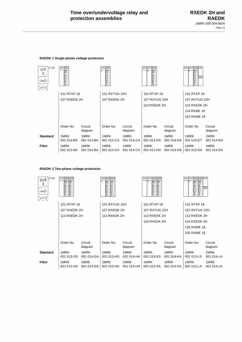
RAEDK 1 Single-phase voltage protection
101 RTXP 18 101 RXTUG 22H 101 RTXP 18 101 RTXP 18
107 RXEDK 2H 107 RXEDK 2H 107 RXTUG 22H 107 RXTUG 22H
113 RXEDK 2H 113 RXEDK 2H
119 RXME 18
319 RXME 18
Order No. Circuitdiagram
Order No. Circuitdiagram
Order No. Circuitdiagram
Order No. Circuitdiagram
Standard 1MRK001 013-BS
1MRK001 014-BA
1MRK001 013-CS
1MRK001 014-CA
1MRK001 013-DS
1MRK001 014-DA
1MRK001 013-ET
1MRK001 014-EA
Filter 1MRK001 013-BA
1MRK001 014-BA
1MRK001 013-CA
1MRK001 014-CA
1MRK001 013-DA
1MRK001 014-DA
1MRK001 013-EA
1MRK001 014-EA
U2
27,59
1=> 0
><107101 107101 113107101
319
119113107101
RAEDK 2 Two-phase voltage protection
101 RTXP 18 101 RXTUG 22H 101 RTXP 18 101 RTXP 18
107 RXEDK 2H 107 RXEDK 2H 107 RXTUG 22H 107 RXTUG 22H
113 RXEDK 2H 113 RXEDK 2H 113 RXEDK 2H 113 RXEDK 2H
119 RXEDK 2H 119 RXEDK 2H
125 RXME 18
325 RXME 18
Order No. Circuitdiagram
Order No. Circuitdiagram
Order No. Circuitdiagram
Order No. Circuitdiagram
Standard 1MRK001 013-GS
1MRK001 014-GA
1MRK001 013-HS
1MRK001 014-HA
1MRK001 013-KS
1MRK001 014-KA
1MRK001 013-LS
1MRK001 014-LA
Filter 1MRK001 013-GA
1MRK001 014-GA
1MRK001 013-HA
1MRK001 014-HA
1MRK001 013-KA
1MRK001 014-KA
1MRK001 013-LA
1MRK001 014-LA
2U2
27,59
1=> 0
><107101 113 107101 113 113107101 119
325
125107101 119113

Time over/undervoltage relay and protection assemblies
RXEDK 2H andRAEDK
1MRK 509 004-BENPage 14
Protectionassemblies (cont’d)
Mountingalternatives
All assemblies can be delivered in the following mounting alternatives:
- on apparatus bars
- in equipment frame 60C
- in RHGX
- in RHGS
RAEDK 3 Three-phase voltage protection
101 RTXP 18 101 RXTUG 22H 101 RTXP 18 101 RTXP 18
107 RXEDK 2H 107 RXEDK 2H 107 RXTUG 22H 107 RXTUG 22H
113 RXEDK 2H 113 RXEDK 2H 113 RXEDK 2H 113 RXEDK 2H
119 RXEDK 2H 119 RXEDK 2H 119 RXEDK 2H 119 RXEDK 2H
125 RXEDK 2H 125 RXEDK 2H
131 RXME 18
331 RXME 18
Order No. Circuitdiagram
Order No. Circuitdiagram
Order No. Circuitdiagram
Order No. Circuitdiagram
Standard 1MRK001 013-NS
1MRK001 014-NA
1MRK001 013-YS
1MRK001 014-YA
1MRK001 013-PS
1MRK001 014-PA
1MRK001 013-ZS
1MRK001 014-ZA
Filter 1MRK001 013-NA
1MRK001 014-NA
1MRK001 013-YA
1MRK001 014-YA
1MRK001 013-PA
1MRK001 014-PA
1MRK001 013-ZA
1MRK001 014-ZA
3U2
27,59
1=> 0
><107101 113 119 107101 113 119 113107101 119 125
331
131107101 113 119 125

Time over/undervoltage relay and protection assemblies
RXEDK 2H andRAEDK
1MRK 509 004-BENPage 15
Ordering Specify RAEDK (Protection):
• Quantity
• Ordering number
• Code U, H, M
• Desired wording on the lower half of the test switch face plate max. 13 lines with 14 characters per line.
Specify RXEDK (Loose Relay):
• Quantity
• Ordering number
Over/undervoltage relay, standard 50-60 Hz
Type Voltage Filter Article No. Code
RXEDK 2H 2/5 V 50-60 Hz (standard) 1MRK 000 841-AA U1
RXEDK 2H 20/50 V 50-60 Hz (standard) 1MRK 000 841-HA U5
RXEDK 2H 100/200 V 50-60 Hz (standard) 1MRK 000 841-RA U9
Over/undervoltage relay; with optional filters
Type Voltage Filter Article No. Code
RXEDK 2H 2/5 V 50-60 Hz (sharp) 1MRK 000 841-BA U2
RXEDK 2H 2/5 V 150-180 Hz (sharp) 1MRK 000 841-CA U3
RXEDK 2H 2/5 V 16 2/3 Hz (flat) 1MRK 000 841-EA U4
RXEDK 2H 20/50 V 50-60 Hz (sharp) 1MRK 000 841-KA U6
RXEDK 2H 20/50 V 150-180 Hz (sharp) 1MRK 000 841-LA U7
RXEDK 2H 20/50 V 16 2/3 Hz (flat) 1MRK 000 841-NA U8
RXEDK 2H 100/200 V 50-60 Hz (sharp) 1MRK 000 841-SA U10
RXEDK 2H 100/200 V 150-180 Hz (sharp) 1MRK 000 841-TA U11
RXEDK 2H 20/50 V 16 2/3 Hz (alternative version) 1MRK 000 841-PA U12
Auxiliary voltage
For included auxiliary relays
Code
24 V dc H5
48-55 V dc H6
110-125 V dc H7
220-250 V dc H8

Time over/undervoltage relay and protection assemblies
RXEDK 2H andRAEDK
1MRK 509 004-BENPage 16
Mounting
Mounting alternatives Size Article No. Code
Apparatus bars M10
Equipment frame without door 4U 19” 1MRK 000 137-GA M11
Equipment frame with door 4U 19” 1MRK 000 137-KA M12
RHGX 4 4U 12C RK 927 001-AB M71
RHGX 8 4U 24C RK 927 002-AB M72
RHGX 12 4U 36C RK 927 003-AB M73
RHGX 20 4U 60C RK 927 004-AB M74
RHGS 30 6U x 1/1 19” rack 1MRK 000 315-A M81
RHGS 12 6U x 1/2 19” rack 1MRK 000 315-B M82
RHGS 6 6U x 1/4 19” rack 1MRK 000 315-C M83

Time over/undervoltage relay and protection assemblies
RXEDK 2H andRAEDK
1MRK 509 004-BENPage 17
References Connection and installation components in COMBIFLEX
Relay accessories COMBIFLEX
User’s Guide RXEDK
1MRK 513 003-BEN
1MRK 513 004-BEN
1MRK 508 008-UEN
Manufacturer ABB Automation Technology Products ABSubstation AutomationSE-721 59 VästeråsSwedenTelephone: +46 (0) 21 34 20 00Facsimile: +46 (0) 21 14 69 18www.abb.com/substationautomation

Time over/undervoltage relay and protection assemblies
RXEDK 2H andRAEDK
1MRK 509 004-BENPage 18