TILT KIT FOR MACDON 70/75/75S - Headsight, Inc. · PDF fileTILT KIT FOR MACDON 70/75/75S...
46
Grain Header Manual 09040120e TILT KIT FOR MACDON 70/75/75S HEADSIGHT.COM | 574.546.5022
Transcript of TILT KIT FOR MACDON 70/75/75S - Headsight, Inc. · PDF fileTILT KIT FOR MACDON 70/75/75S...

Grain Header Manual09040120e
TILT KIT FORMACDON 70/75/75S
HEADSIGHT.COM | 574.546.5022


About Headsight
Headsight Contact InfoHeadsight, Inc. 4845 3B Road Bremen, IN 46506 Phone: 574-546-5022 Fax: 574-546-5760 Email: [email protected] Web: www.headsight.com
Technical AssistancePhone: 574-220-5511
About this Manual
How to use this manualThe instructions in this manual are in the order that they should be completed for new installations. Complete all applicable instructions in each section before proceeding. Note that some sections are labeled to indicate they only apply to certain machines or applications. An index is available in the front of the manual to help find technical information for previously installed systems.
This icon designates information of which you should take note.
This icon indicates a special tool needed for a given task.
This icon designates an important instruction.
DisclaimersHeadsight®, Horizon®, Pinpoint®, Insight®, Foresight®, Feathersight® Truesense™ and Truesight® are trademarks of Headsight, Inc. All other trademarks are property of their respective owners.
SuggestionsIf you have any suggestions to improve this manual please call 574-546-5022 or email [email protected].
Headsight’s products are protected by one or more of the following US Patents 6202395, 6833299, 7310931, 7647753 and other patents pending.
Copyright Headsight, Inc. 2017

Table of ContentsAbout Headsight ��������������������������������������������������������������������������������������������� iAbout this Manual ������������������������������������������������������������������������������������������� iInstallation �������������������������������������������������������������������������������������������������� 1
Identify Mounting Style ���������������������������������������������������������������������������������� 2Installing Sensors ���������������������������������������������������������������������������������������� 3Install Sensor Wiring ������������������������������������������������������������������������������������ 5Install Main Harness-Wiring ���������������������������������������������������������������������������� 6
For kits w/ Insight box ��������������������������������������������������������������������������������� 6For kits w/o the Insight box �������������������������������������������������������������������������� 6CNH and JD 50 Series ���������������������������������������������������������������������������������� 7JD 60 Series and AGCO MY2002 and newer �������������������������������������������������������� 8Lexion ���������������������������������������������������������������������������������������������������� 8
Calibration ��������������������������������������������������������������������������������������������������� 9Sensor Adjustment (w/o Insight Box) ����������������������������������������������������������������� 9Sensor Adjustment (with Insight Box) ���������������������������������������������������������������10All Combines ���������������������������������������������������������������������������������������������11
CaseIH w/ Gen2 Software & New Holland CR �����������������������������������������������������11CaseIH w/ Gen1 Software ����������������������������������������������������������������������������11JD S-Series ����������������������������������������������������������������������������������������������12JD 70 Series ���������������������������������������������������������������������������������������������12JD 50 and 60 Series ������������������������������������������������������������������������������������13Lexion 400 & 500 ��������������������������������������������������������������������������������������14Lexion 600 & 700 ��������������������������������������������������������������������������������������14AGCO Axial 2009 and newer �������������������������������������������������������������������������14AGCO 2008 and earlier, Gleaner ���������������������������������������������������������������������14
Settings ������������������������������������������������������������������������������������������������������15Enable Lateral Tilt ���������������������������������������������������������������������������������������15
CNH ������������������������������������������������������������������������������������������������������15CIH 14-25xx �������������������������������������������������������������������������������������������15JD S-Series ����������������������������������������������������������������������������������������������15JD 50-70 �������������������������������������������������������������������������������������������������16Lexion ��������������������������������������������������������������������������������������������������16AGCO Axial 2009 and newer �������������������������������������������������������������������������16Gleaner R-S, early Axial �������������������������������������������������������������������������������16
Adjust Sensitivity ����������������������������������������������������������������������������������������17CIH Flagship, NH-CR, x140 ���������������������������������������������������������������������������17CIH x088, x130 �����������������������������������������������������������������������������������������17CIH 14-25xx ��������������������������������������������������������������������������������������������17JD 70- S-Series ������������������������������������������������������������������������������������������18JD 60 Series STS ����������������������������������������������������������������������������������������18JD 50-60 Series (Non-STS)����������������������������������������������������������������������������18Lexion 400 & 500 ��������������������������������������������������������������������������������������19Lexion 600 & 700 �������������������������������������������������������������������������������������19AGCO Axial 2009 and newer �������������������������������������������������������������������������19

Gleaner R-S, early Axial �������������������������������������������������������������������������������19Operation ���������������������������������������������������������������������������������������������������20
Setting Automatic Control Height ���������������������������������������������������������������������20CNH ������������������������������������������������������������������������������������������������������20John Deere ����������������������������������������������������������������������������������������������20Lexion ���������������������������������������������������������������������������������������������������20AGCO 2009- up, except Rxx, Sxx ���������������������������������������������������������������������21AGCO 1998-2008, Rxx, Sxx ��������������������������������������������������������������������������21
Testing Operation ���������������������������������������������������������������������������������������22Overview ����������������������������������������������������������������������������������������������������23
Insight® Navigation ��������������������������������������������������������������������������������������23How to Navigate ����������������������������������������������������������������������������������������23Meaning of Status Light �������������������������������������������������������������������������������23Resetting Insight® to Defaults �����������������������������������������������������������������������23
Advanced Information ������������������������������������������������������������������������������������24Lexion Calibration issues ������������������������������������������������������������������������������24
Diagnostics �������������������������������������������������������������������������������������������������25Reading Voltages w/ Sensor Tester �������������������������������������������������������������������25Reading Voltages w/ Insight ��������������������������������������������������������������������������26
Before you Start ���������������������������������������������������������������������������������������26On the Insight® Box������������������������������������������������������������������������������������26
Troubleshooting by Symptom �������������������������������������������������������������������������27Schematics ������������������������������������������������������������������������������������������������29
HB2-IH8S-31C ������������������������������������������������������������������������������������������30HP2-JD63-31Q (Continued on next page)����������������������������������������������������������31HP2-JD63-31Q (Continued) ��������������������������������������������������������������������������32HB2-CA05-XX �������������������������������������������������������������������������������������������33HP2-AG31-31A (Continued on next page) ���������������������������������������������������������34HP2-AG31-31A (Continued) �������������������������������������������������������������������������35QB2-IH23-XX �������������������������������������������������������������������������������������������36QB3-NHCR-31N ����������������������������������������������������������������������������������������37
Parts ���������������������������������������������������������������������������������������������������������38MacDon Tilt Sensor �������������������������������������������������������������������������������������38Harness ���������������������������������������������������������������������������������������������������39
STATEMENT OF LIMITED WARRANTY �����������������������������������������������������������������40

1
Installation
Installation
Before working under header always:
1. Perform all combine and header manufacturer safety precautions for servicing header.
2. Insert stop to prevent movement of header.
3. Turn off combine and remove key from ignition.
4. Set combine parking brake.
5. Disconnect all drive shafts from the header.
2
Installation
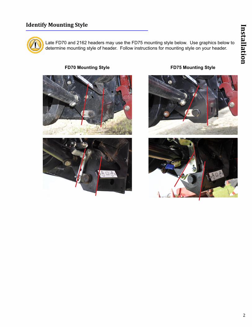
Identify Mounting Style
Late FD70 and 2162 headers may use the FD75 mounting style below. Use graphics below to determine mounting style of header. Follow instructions for mounting style on your header.
FD70 Mounting Style FD75 Mounting Style

3
Installation
Installing Sensors
1. Attach sensor assembly stamped (L) with large offset to left side of header float adapter.
• Use hardware provided• Secure sensor wiring with small clamp on upper bolt
marked A• Remove triangle adapter bracket as shown (marked
B) for FD70 and older model heads
2. Attach arm bracket to float arm using existing hole and hardware provided.
3. Install sensor linkage rod in center hole of arm bracket and outer hole in sensor assembly arm with nuts toward inside.
• FD75 and newer model heads • Use preassembled tie rods (4 1/2” threaded rod) • Set the length to 5 7/8” from center of eyelet to
center of eyelet for initial setting• FD70 and older model heads
• Swap eyelets to use 6 1/2” threaded rods• Set tie rod length to 8” from center of eyelet to
center of eyelet for initial setting
A
B
4
Installation
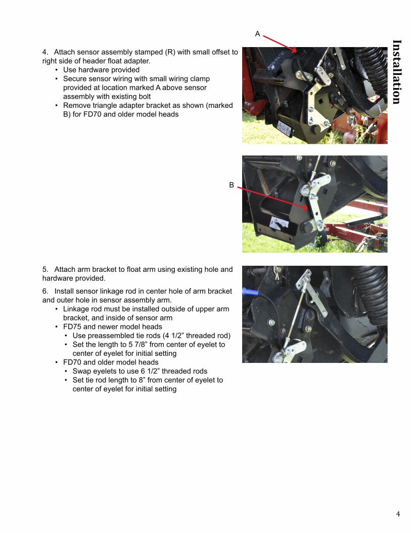
4. Attach sensor assembly stamped (R) with small offset to right side of header float adapter.
• Use hardware provided• Secure sensor wiring with small wiring clamp
provided at location marked A above sensor assembly with existing bolt
• Remove triangle adapter bracket as shown (marked B) for FD70 and older model heads
5. Attach arm bracket to float arm using existing hole and hardware provided.
6. Install sensor linkage rod in center hole of arm bracket and outer hole in sensor assembly arm.
• Linkage rod must be installed outside of upper arm bracket, and inside of sensor arm
• FD75 and newer model heads • Use preassembled tie rods (4 1/2” threaded rod) • Set the length to 5 7/8” from center of eyelet to
center of eyelet for initial setting• FD70 and older model heads
• Swap eyelets to use 6 1/2” threaded rods• Set tie rod length to 8” from center of eyelet to
center of eyelet for initial setting
A
B
5
Installation
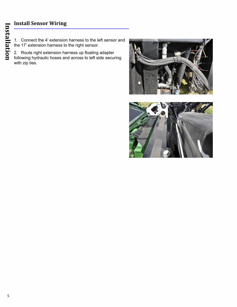
Install Sensor Wiring
1. Connect the 4’ extension harness to the left sensor and the 17’ extension harness to the right sensor.
2. Route right extension harness up floating adapter following hydraulic hoses and across to left side securing with zip ties.

6
Installation
Install Main Harness-Wiring
Before mounting Insight, make sure the main harness will reach to the OEM header plug (see combine specific section below).
For kits w/ Insight box1. Mount Insight to back of header with the bracket shown.
2. Connect the Y101 to the Insight box.
3. Connect sensor extension harnesses.• Connect right sensor extension harness to connector
marked R on main harness• Connect left sensor extension harness to connector
marked L on main harness• Center is not used
For kits w/o the Insight box
1. Install the Main harness for your combine (see combine specific section below).
2. Connect sensor extension harnesses.• Connect right sensor extension harness to connector
marked R on main harness• Connect left sensor extension harness to connector
marked L on main harness
C RL
R
L
7
Installation
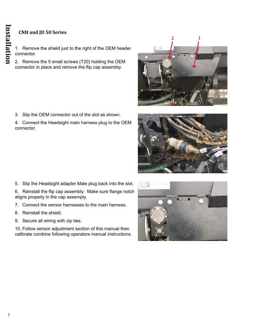
CNH and JD 50 Series
1. Remove the shield just to the right of the OEM header connector.
2. Remove the 5 small screws (T20) holding the OEM connector in place and remove the flip cap assembly.
3. Slip the OEM connector out of the slot as shown.
4. Connect the Headsight main harness plug to the OEM connector.
5. Slip the Headsight adapter Male plug back into the slot.
6. Reinstall the flip cap assembly. Make sure flange notch aligns properly in the cap assemply.
7. Connect the sensor harnesses to the main harness.
8. Reinstall the shield.
9. Secure all wiring with zip ties.
10. Follow sensor adjustment section of this manual then calibrate combine following operators manual instructions.
2 1

8
Installation
JD 60 Series and AGCO MY2002 and newer
1. Connect main harness to existing header connector and route opposite connector to combine connection location.
2. Connect Y161 and Y162 inline with MacDon selector harness connection.
3. Secure all wiring with zip ties.
4. Follow sensor adjustment section of this manual then calibrate combine following operators manual instructions.
Lexion
1. Identify the OEM MacDon AHHC sensor in center of header frame.
2. Trace the existing harness from OEM MacDon AHHC sensor to the Multilink.
3. Disconnect the OEM harness from the Multilink port VS2. (see note below)
4. Connect the Headsight harness to the Multilink port VS2 in place of the OEM harness. The OEM harness and sensor are not used.
5. Secure all wiring with zip ties.
6. Follow sensor adjustment section of this manual then calibrate combine following operators manual instructions.
Some MacDon heads may have the location of Ports VS2 and VS3 reversed. Make sure you trace the harness from the OEM sensor in the middle of the head and replace that harness plug with the Headsight with connnector Y501.
VS2 VS3

9
Calibration
Calibration
When calibrating/adjusting sensors always:• Run reel fully forward for maximum “out front” weight• Ensure Center Link is set to D • Make sure the head has full motion. The float springs cannot be so tight that the head frame
“floats up” when the head is fully raised. If necessary, loosen the springs during calibration, then retighten to desired setting. NOTE: Lexions in particular have this issue, as they raise the head significantly higher than other combines, causing it to roll back farther and float up more.
Sensor Adjustment (w/o Insight Box)
1. Plug in sensor tester to sensor being adjusted.
2. Loosen sensor tie rod linkage jam nuts.
3. Adjust length of tie rod to proper voltage. • Increase length of tie rod to decrease voltage• Decrease length of tie rod to increase voltage• Header raised voltage = 3.5-4.3V• Header lowered voltage = 0.8-1.5V• Sensor change must have a range greater than 2.0V• Voltage range on left and right sensor should match
closely
4. Tighten tie rod linkage jam nuts.
5. Disconnect sensor tester and reconnect extension harness.

10
Calibration
Sensor Adjustment (with Insight Box)
1. Start combine to power the Insight box.
2. Setup Insight box (this will only need to be done the first time you power up Insight).• Choose Language• Choose Combine Brand• Choose Combine Model • Choose “Draper” as header type• Choose “2” sensors
Before pressing the check button to begin calibrating, be sure to adjust voltages at this screen by adjusting sensors tie rod length.
3. Using the Left and Right voltage inputs displayed on the Insights box, raise and lower the header and adjust the tie rod lengths so the voltages are in the correct range.
• Increase length of tie rod to decrease voltage• Decrease length of tie rod to increase voltage• Header raised voltage = 3.5-4.3V• Header lowered voltage = 0.8-1.5V• Sensor change must have a range greater than 2.0V• Voltage range on left and right sensor should match
close as possible
4. Tighten tie rod linkage jam nuts.
5. Park the combine on a smooth, level surface - preferably a cement driveway or shop floor.
6. Follow on-screen instructions.• “Raise Header” all the way so that NO sensors touch
the ground and press enter• “Lower Header” all the way down on the skids and
press enter
Raise HeaderThen Press (✓)LEFT RIGHT0.0V 0.0V

11
Calibration
All Combines
You may wish to refer to both your MacDon and combine Owners Manuals for details on Setup and Calibration of the AHC. Also, Headsight has much more detailed combine operation information in specific “combine” manuals available on our website at headsight.com/manuals. Use the manual search to select & download these manuals.
When calibrating/adjusting sensors always:• Run reel fully forward for maximum “out front” weight• Ensure Center Link is set to D • Make sure the head has full motion. The float springs cannot be so tight that the head frame
“floats up” when the head is fully raised. If necessary, loosen the springs during calibration, then retighten to desired setting. NOTE: Lexions in particular have this issue, as they raise the head significantly higher than other combines, causing it to roll back farther and float up more.
CaseIH w/ Gen2 Software & New Holland CR
For CaseIH Flagship w/ Gen2 Software, Midrange x140, and New Holland CR combines.
If you do not have a “Header” selection under Calibrations, see Gen 1 section
1. Make sure header type under “Toolbox>>Head1” is set correctly.
2. Choose Calibrations>>Header.• Follow the on-screen steps
3. After successful calibration, set initial AHC #1 at lowest height on Macdon indicator.
CaseIH w/ Gen1 Software
For CaseIH Flagship w/Gen 1 Software, 21-25xx, x088, x130, combines.
1. Thresher and header must be off. Lower head fully to ground and hold for 3 seconds. Press and Hold Raise button until head reaches top of motion.
• Header should pause ~12” off the ground• NO “S1” header code should appear in the corner post during or after calibration
12
Calibration
JD S-Series
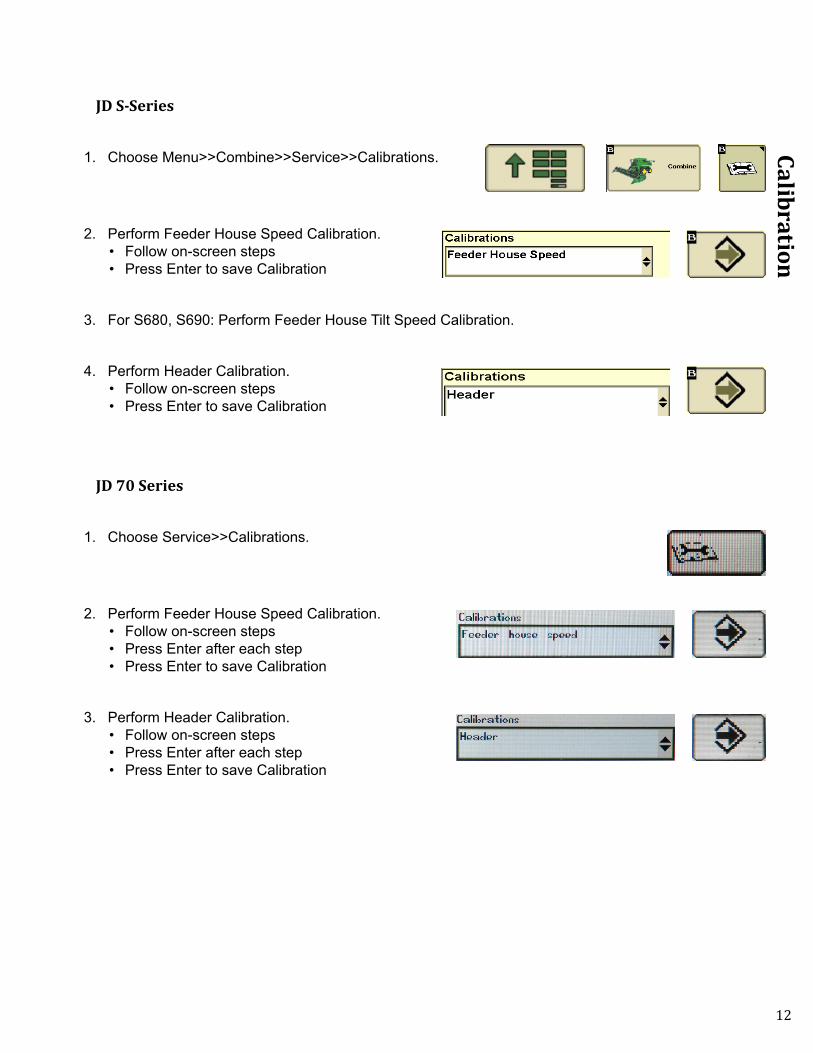
1. Choose Menu>>Combine>>Service>>Calibrations.
2. Perform Feeder House Speed Calibration.• Follow on-screen steps• Press Enter to save Calibration
3. For S680, S690: Perform Feeder House Tilt Speed Calibration.
4. Perform Header Calibration.• Follow on-screen steps• Press Enter to save Calibration
JD 70 Series
1. Choose Service>>Calibrations.
2. Perform Feeder House Speed Calibration.• Follow on-screen steps• Press Enter after each step• Press Enter to save Calibration
3. Perform Header Calibration.• Follow on-screen steps• Press Enter after each step• Press Enter to save Calibration

13
Calibration
JD 50 and 60 Series
1. Press button on cornerpost and then press until the screen reads “CAL”.
2. Press and then press until the screen reads “Hdr”.
3. Press screen will read “Hdr – dn” and lower the header completely to the ground.
4. Press screen will read “Hdr – up” and raise the header to the top of its stroke.
5. Press screen will read “EOC” and then press .
6. Press until returned to the main screen.
14
Calibration
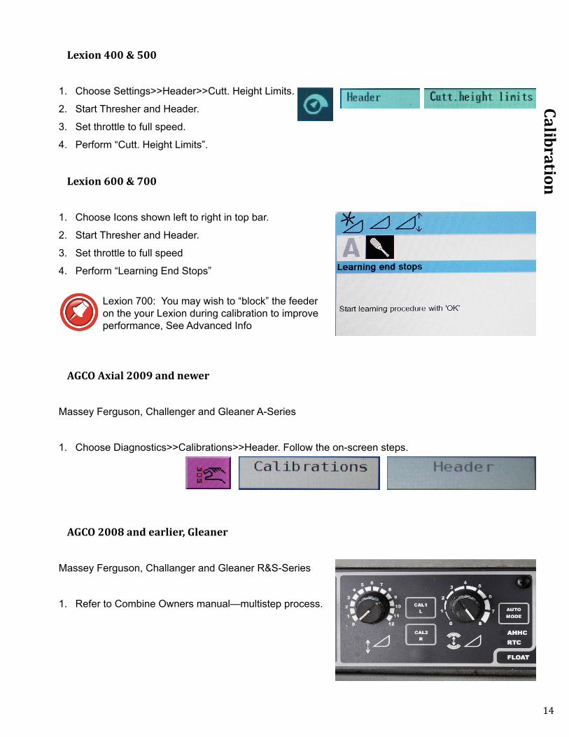
Lexion 400 & 500
1. Choose Settings>>Header>>Cutt. Height Limits.
2. Start Thresher and Header.
3. Set throttle to full speed.
4. Perform “Cutt. Height Limits”.
Lexion 600 & 700
1. Choose Icons shown left to right in top bar.
2. Start Thresher and Header.
3. Set throttle to full speed
4. Perform “Learning End Stops”
Lexion 700: You may wish to “block” the feeder on the your Lexion during calibration to improve performance, See Advanced Info
AGCO Axial 2009 and newer
Massey Ferguson, Challenger and Gleaner A-Series
1. Choose Diagnostics>>Calibrations>>Header. Follow the on-screen steps.
AGCO 2008 and earlier, Gleaner
Massey Ferguson, Challanger and Gleaner R&S-Series
1. Refer to Combine Owners manual—multistep process.

15
Settings
Settings
Enable Lateral Tilt
CNH
1. Choose Toolbox>>Head2.
2. Enable Lateral Tilt, “Installed” or “Yes”.
3. Header Sensors should also be “Installed” (some combines do not have this option).
CIH 14-25xx 1. Turn on Field Tracker.
JD S-Series
1. Enable on the combine cornerpost.• Header height control• Header height resume• Contour Master

16
Settings
JD 50-70
1. Enable on the combine cornerpost.• Header height control• Header height resume• Contour Master
Lexion 1. Set Selector switch is Lateral Tilt Mode (500 shown, 700 similar).
AGCO Axial 2009 and newer
1. Make sure the Lateral Tilt switch is on.
Gleaner R-S, early Axial
1. Enable the lateral tilt Icon .
17
Settings
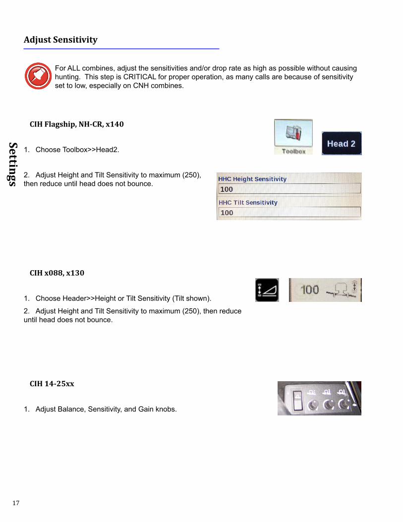
Adjust Sensitivity
For ALL combines, adjust the sensitivities and/or drop rate as high as possible without causing hunting. This step is CRITICAL for proper operation, as many calls are because of sensitivity set to low, especially on CNH combines.
CIH Flagship, NH-CR, x140
1. Choose Toolbox>>Head2.
2. Adjust Height and Tilt Sensitivity to maximum (250), then reduce until head does not bounce.
CIH x088, x130
1. Choose Header>>Height or Tilt Sensitivity (Tilt shown).
2. Adjust Height and Tilt Sensitivity to maximum (250), then reduce until head does not bounce.
CIH 14-25xx
1. Adjust Balance, Sensitivity, and Gain knobs.
18
Settings
JD 70- S-Series
1. Set the AHHC height and tilt sensitivity.• Press the header button repeatedly until AHHC sensitivity or contour master sensitivity displays• Use scroll knob to adjust sensitivity
JD 60 Series STS
1. Set the automatic drop rate.• Use the knob under the operator’s right-hand armrest
JD 50-60 Series (Non-STS)
1. Set the automatic drop rate.• Use the adjustment on the valve block
2. Set the hydraulic accumulator.• Open the accumulator valve 1 full turn (from closed position)
3. Manually move header from full right tilt to full left tilt.• The target tilt speed is 5-8 seconds• If not correct, download JD 506070S Manual online from our website to for instructons on how to
change tilit orfices

19
Settings
Lexion 400 & 500
1. Choose Settings>>Header>>Sensitivity CAC.• Adjust to optimize performance
Lexion 600 & 700
1. Choose Icons shown Left to right in Top Bar
2. Choose Sensitivity CAC:• Cutting Height Adjustment: This is Height
sensitivity• Lateral Leveling: Tilt sensitivity• Automatic Drop rate—Suggested-40
AGCO Axial 2009 and newer
1. Choose Header>>Tilt.• Adjust Sensitivities
2. Choose AHHC.• Adjust Sensitivity
3. Choose Table Settings.• Adjust Flow Rates
Gleaner R-S, early Axial
1. Adjust sensitivity knobs. • If head bounces vertically at minimal sensitivity, the Headsight Flow Rate
Kit is recommended
20
Operation
Operation
Setting Automatic Control Height
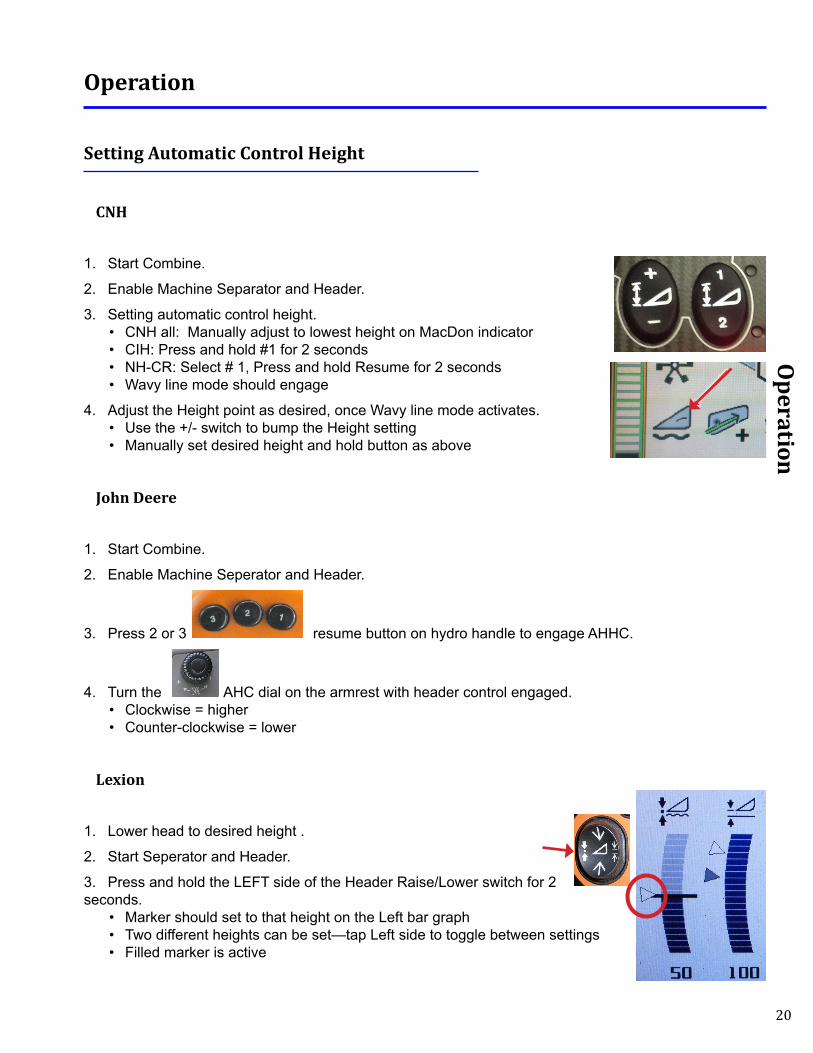
CNH
1. Start Combine.
2. Enable Machine Separator and Header.
3. Setting automatic control height.• CNH all: Manually adjust to lowest height on MacDon indicator • CIH: Press and hold #1 for 2 seconds• NH-CR: Select # 1, Press and hold Resume for 2 seconds • Wavy line mode should engage
4. Adjust the Height point as desired, once Wavy line mode activates.• Use the +/- switch to bump the Height setting• Manually set desired height and hold button as above
John Deere
1. Start Combine.
2. Enable Machine Seperator and Header.
3. Press 2 or 3 resume button on hydro handle to engage AHHC.
4. Turn the AHC dial on the armrest with header control engaged.• Clockwise = higher• Counter-clockwise = lower
Lexion
1. Lower head to desired height .
2. Start Seperator and Header.
3. Press and hold the LEFT side of the Header Raise/Lower switch for 2 seconds.
• Marker should set to that height on the Left bar graph• Two different heights can be set—tap Left side to toggle between settings• Filled marker is active
21
Operation
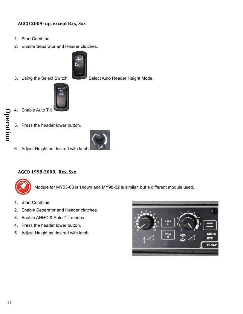
AGCO 2009- up, except Rxx, Sxx
1. Start Combine.
2. Enable Separator and Header clutches.
3. Using the Select Switch, Select Auto Header Height Mode.
4. Enable Auto Tilt
5. Press the header lower button.
6. Adjust Height as desired with knob .
AGCO 1998-2008, Rxx, Sxx
Module for MY03-08 is shown and MY98-02 is similar, but a different module used.
1. Start Combine.
2. Enable Separator and Header clutches.
3. Enable AHHC & Auto TIlt modes.
4. Press the header lower button.
5. Adjust Height as desired with knob.

22
Operation
Testing Operation
1. Raise head fully.
2. Engage Separator and Header.
3. Manually tilt head fully to either side.
4. Enable automatic header control.
5. Header should drop to preselected height and Float Optimizer should level itself to the header frame.

23
Overview
Overview
Insight® Navigation
How to NavigateWhen in a menu (selection arrow appears to left side)
• Enter: chooses the selected menu choice• Esc: backs up one menu level• Up: moves up within the menu choices displayed • Down: moves down within the menu choices displayed
When in a screen which allows setting of parameters• Enter: backs up to last menu level AFTER saving• Esc: backs up to last menu level without saving• Up: increases the value• Down: decreases the value
Meaning of Status LightSolid Green:
• System is operating• No errors detected
Solid Red:• System is NOT operating• No height or tilt signals are sent to combine• You have changed settings which require calibration of Insight, are currently in a menu which will
force a calibration if you make any changes, or are in calibration mode
Solid Green with Flashing red:• System is operating• An error has been detected• Repair problem then clear errors
Flashing Red:• System is operating• A sensor has been ignored• See note in Troubleshooting by Error - ER16• Repair system - Recalibrate Insight
Resetting Insight® to DefaultsTo reset all settings hold + for 5 seconds:
• Press and hold ESC then• Press and hold Enter while holding Esc• Hold both for 5 seconds

24
Advanced Info
Advanced Information
Lexion Calibration issues
For Lexion 6/700 machines with 2011-2014 OEM Lexion software, play in the connection between the header and feeder house can cause the calibration process to not work correctly. Symptom: When the CAC system is engaged, the header dives into the ground, then recovers to the preset height.
MacDon Flex Draper headers can experience this symptom. Limiting downward over-travel on the float adapter during calibration may solve or reduce this issue. If your feeder can continue to drop more than ½” after the float optimizer reaches maximum normal operating travel downward, it is recommended that you use the following solution:
During the combine calibration process, use blocks under the feeder faceplate to stop further movement downward The block height should stop the feeder just as the solid frame of the float optimizer reaches maximum normal operating travel downward (indicator stops moving).
Many Lexion operators of all models claim that using this technique improves performance in the field, both for the OEM MacDon sensor, and with the Headsight Tilt option.
1. Park the combine and head on a firm, level surface.
2. Make sure head angle is tilted fully forward (set to D).
3. Run reel fully forward for maximum out front weight.
4. Make sure lift springs are not so tight head floats up when fully raised.
5. Lower the head until the skids contact the ground.
6. Level the header/feeder.
7. Continue to lower the feeder while watching the height range indicator. The indicator should drop toward 0-1.
8. When the indicator stops moving, the float optimizer should have reached maximum downward travel.
9. NOTE: it might take several cycles to identify the best height to stop the travel at.
10. Block under the center of the feeder faceplate to make sure feeder cannot lower further.
11. Perform the combine calibration.• Lexion 4-500: Perform “Cutting Height Limits” • Lexion 6-700: Perform “Learning End Stops”
12. Remove the blocking and test operation.

25
Diagnostics
Diagnostics
Reading Voltages w/ Sensor Tester
1. There are to options for testing sensor and wiring.• To test the sensor only, connect the sensor tester directly to the sensor connector• To test the sensor harness, connect the tester to the sensor extension harness at the rear of the
header (Harness must be connected to the sensor)
2. Turn on the sensor tester and read the voltage. Raise and lower header thru its range and watch the voltage change.
3. Typical sensor readings (See Typical sensor readings and Common faults for more information.• Sensor when header is raised: 4.0V (+/- 0.2V) • Sensor when header is completely pressed on the ground: 0.8-1.5V • Smooth change between upper and lower voltages
Common faults
• Sensor Tester reads 4.75-4.85V, as sensor arm is moved through its range• A & C are reversed in the harness
• Sensor Tester reads 5V, no change• Check wire A (ground) to sensor for open
• Sensor Tester reads 0V, as sensor arm is moved through its range• Check wire C (5V) to sensor for open• Check wire B (signal) from sensor for open• Check that magnet is still in shaft
• Sensor Tester voltage jumps erratically at a point in the rotation• Replace sensor
• Sensor Tester reads 0.3V, as sensor arm is moved through its range• The sensor is beyond its mechanical travel• Sensor operates “backwards” (1.0V-sensor down, 4.0V-sensor up)• Rotate sensor 180 degrees on mounting
• CALL HEADSIGHT BEFORE REPLACING SENSOR (TECH SUPPORT 1-574-220-5511)• The sensor is rarely the cause of problem

26
Diagnostics
Reading Voltages w/ Insight
Before you Start
The Insight box can display both the input voltages it receives from each sensor and the output voltages it is sending to the combine.
Sensor voltage = Insight box input voltage Insight box output voltage = Combine sensor input
On the Insight® Box1. From main menu, go to >> Diagnostics>>Disp Sensor Voltages.
• This shows real-time voltage coming from each sensor
2. For more information about sensor history and status see >>Diagnostics>>Detailed Diagnostics>>(parameter of interest).
• Sensor = signal from sensor in volts• Max = the maximum voltage sent to Insight box from sensor since last calibrated• Min = the minimum voltage sent to Insight box from sensor since last calibrated• Enabled = is this sensor enabled to control height? Yes or No• SetH = the “header raised” voltage set-point recorded during calibration• SetL = the “header lowered” voltage set-point recorded during calibration• Reversed = is the polarity of this sensor reversed? Yes or No
Sensor Voltages
L LC CTR RC R0.0 0.0 0.0 0.0 0.0
Left Sens =0.00VMax=0.00V SetH=5.00VMin=0.00V SetL=0.00VEnabled=N Reversed=N

27
Diagnostics
Troubleshooting by Symptom
Nearly every problem may be resolved by one of the following simple steps:• Make sure each sensor meets the basic requirements discussed above• Properly calibrate • Properly set the combine performance settings
Symptom Problem SolutionSystem does not tilt Tilt function not enabled on
combineCorrect in accordance with the Settings section of this manual
Insight not calibrated (if applicable)
Calibrate Insight
Combine not calibrated Correct in accordance with the Calibration section of this manual
Wiring not installed correctly See Installation SectionLexion: make sure Headsight adapter harness is connected to OEM AHC portOther: Make sure adapter harness is teed into OEM harnessMake sure sensor wires are connected
Header/ feeder tilts wrong way (either direction)
Left and right sensor connections reversed on main harness
Correct in accordance with the Installation section of this manual
Sensors incorrectly installed or adjusted
Correct in accordance with the Installation section of this manual
Header/feeder tilts fully one direction only
Sensors incorrectly installed or adjusted
Correct in accordance with the Installation section of this manual
Incorrect calibration Make sure voltages are correct
Make sure springs are not to tight during calibration
Combine will not calibrate header Sensors incorrectly installed or adjusted
Correct in accordance with the Installation section of this manual
Make sure voltage ranges are correct
Incorrect Insight calibration (where applicable)
Calibrate Insight
Head is floating up on float springs when raised
Make sure springs are not to tight during calibration
Header dives then recovers Drop rate set to high Lower Automatic Drop rateLexion Cal issue See Advanced Info

28
Diagnostics
Symptom Problem SolutionHeader response sluggish Height and/or Tilt Sensitivities set
too lowIncrease sensitivity as much as possible without head hunting
Flow rates set too low (when adjustable)
Increase flow rates as much as possible without head hunting

29
Diagnostics
Schematics
The following schematics are the main harnesses used for most applications in this manual, locate your harness part number then refer to schematic harness numbers.

30
Diagnostics
081
LEFT
SEN
SOR
WH
T
087
RIG
HT
SEN
SOR
WH
T
012
12V
POW
ER R
ED
082
L C
SEN
SOR
WH
T
032
RIG
HT
HZD
LT
Dk
GR
N
150
SWAP
3 P
UR
137
SWAP
2 D
k BL
U
022
CH
ASSI
S G
ND
BLK
070
HEA
DER
TYP
E
YEL
131
DR
APER
- B
RN
130
DR
APER
+ W
HT
031
LEFT
HZD
LT
YEL
136
SWAP
1 O
RG
Y311
CO
MBI
NE
P01
LEFT
HG
T
P02
RIG
HT
HG
T
P05
SEN
SOR
V+
P06
SEN
SOR
GN
D
P03
L C
HG
T
P04
RT
C H
GT
P07
REE
L SP
EED
P08
DEC
K PL
ATE
P09
REE
L VE
RT
P10
SWAP
3
P12
SEN
SOR
V+
P13
SEN
SOR
GN
D
P18
DR
APER
+
P19
DR
APER
-
P20
DEC
K +
P22
LFT
HZD
LT
P23
SEN
SOR
V+
P24
STU
BBLE
LTS
P25
SEN
SOR
GN
D
P26
DEC
K -
P27
HEA
DER
TYP
E
P28
RIG
HT
HZD
LT
P29
SWIT
CH
ED 1
2V
P30
CH
ASSI
S G
ND
P31
FLEX
PR
ESSU
RE
Y312
HEA
DER
P05
SEN
SOR
V+
P06
SEN
SOR
GN
D
P01
L H
GT
P03
L C
HG
T
P04
RT
C H
GT
P02
RT
HG
T
P07
REE
L SP
EED
P08
DEC
K PL
ATE
P09
REE
L VE
RT
P10
SWAP
3
P12
SEN
SOR
V+
P13
SEN
SOR
V-
P18
DR
APER
+
P19
DR
APER
-
P20
DEC
K +
P22
LEFT
HZD
LT
P23
SEN
SOR
V+
P24
STU
BBLE
LT
P25
SEN
SOR
GN
D
P26
DEC
K -
P27
HEA
DER
TYP
E
P28
RIG
HT
HZD
LT
P29
12V
POW
ER
P30
CH
ASSI
S G
ND
P31
FLEX
PR
ESSU
RE
033
STU
BBLE
LTS
BR
N
S81
LEFT
HG
TA
GR
OU
ND
BSI
GN
AL
CSE
NSO
R V
+
S87
RIG
HT
HG
TA
GR
OU
ND
BSI
GN
AL
CSE
NSO
R V
+
108
AUX
SNR
GN
D L
t BLU
058
AUX
SNR
V+
PIN
K
101
SEN
SOR
GN
D L
t BLU
051
SEN
SOR
PW
R P
INK
100
SEN
SOR
GN
D L
t BLU
050
SEN
SOR
V+
PIN
K
098
REE
L SP
EED
GR
Y
113
REE
L F/
A Y
EL
112
REE
L VE
RT
YEL
091
FLEX
PR
ESSU
RE
GR
Y
086
RT
C S
ENSO
R W
HT
NO
TES:
HB2
-IH8S
-31C
5
HB2-IH8S-31C

31
Diagnostics
045 RIG
HT H
GT TAN
100 SENSO
R G
ND
Lt BLUE
041 LEFT HG
T TAN
050 SENSO
R PW
R PIN
K
031 LEFT HZD
LT YEL
032 RIG
HT H
ZD LT D
k. GR
N
033 STUBBLE LTS BR
N
022 CH
ASSIS GN
D BLK
012 12V POW
ER R
ED
043 CTR
HG
T TAN
S81
LEFT HEIGHTA GROUND
B SIGNAL
C 5V POWER
S87
RIGHT HEIGHTA GROUND
B SIGNAL
C 5V POWER
098 REEL SPEED
GR
Y
113 REEL F/A YEL
112 REEL VER
T YEL
131 DR
APER - BR
N
097 SHAFT SPEED
GR
Y
130 DR
APER + W
HT
078 REEL SELEC
T Dk BLU
804 FLOAT SO
L 2 YEL
465A RH
DEC
K SHIFT G
RN
466A LH D
ECK SH
IFT BLU
Y201C
OM
BINE
P07L H
HEIG
HT
P03L H
FLOAT
P09R
H H
EIGH
T
P20SEN
SOR
V+
P10SEN
SOR
GN
D
P01C
RO
P 2 R
P02C
RO
P 1 L
P04SW
ITCH
ED 12V
P05R
H FLO
AT
P06TILT SO
L
P08R
EEL SPEED
P11R
EEL SOL
P12C
HASSIS G
ND
P13LFT H
ZD LT
P14R
IGH
T HZD
LT
P15STU
BBLE LTS
P16H
DR
REC
1
P17H
DR
REC
3
P18H
DR
REC
4
P19FLEX SELEC
T
P21R
EEL SELECT
P23R
H SH
IFT
P24L H
SHIFT
P25FLO
AT SOL 2
P26D
RAPER
+
P27D
RAPER
-
P28H
EADER
REC
2
P29SH
AFT SPEED
P30R
EEL VERT SIG
P31R
EEL F/A SIG
072 HD
R R
EC 2 O
RG
Y202H
EADER
P03C
TR H
GT SN
S
P20SEN
SOR
V+
P10SIG
NAL G
ND
P01C
RO
P 2 R
P02C
RO
P 1 L
P04SW
ITCH
ED 12V
P05R
H FLO
AT
P06TILT SO
L
P08R
EEL SPEED
P11R
EEL SOL
P12C
HASSIS G
ND
P13LEFT H
ZD LT
P14R
IGH
T HZD
LT
P15STU
BBLE LTS
P16H
EADER
REC
1
P17H
EADER
REC
3
P18H
EADER
REC
4
P19FLEX SELEC
T
P21R
EEL SELECT
P23R
H SH
IFT
P24L H
SHIFT
P25FLO
AT SOL 2
P26D
RAPER
+
P27D
RAPER
-
P28H
EADER
REC
2
P29SH
AFT SPEED
P30R
EEL VERT
P31R
EEL F/A
073 HD
R R
EC 3 O
RG
079 FLEX SELECT O
RG
071 HD
R R
EC 1 O
RG
074 HD
R R
EC 4 O
RG
464 REEL SO
L YEL
813 RH
FLOAT G
RY
803 TILT DIV SO
L OR
G
781 CR
OP 1 L W
HT
782 CR
OP 2 R
WH
T
NO
TES:
HP2-JD
63-31Q3
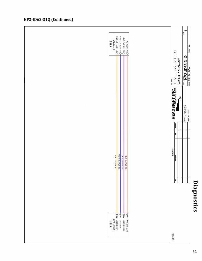
HP2-JD63-31Q (Continued on next page)
32
Diagnostics
137
SWAP
2 D
k BL
U
Y161
SWAP
EXT
P01
L H
HEI
GH
T
P02
L H
FLO
AT
P03
R H
HEI
GH
T
P04
REE
L F/
A SI
G
Y162
SWAP
EXT
P01
CTR
HG
T SN
S
P02
CTR
HG
T SN
S
P03
SIG
NAL
GN
D
P04
REE
L F/
A
136
SWAP
1 O
RG
150
SWAP
3 P
UR
157
SWAP
4 B
RN
NO
TES:
HP2
-JD
63-3
1Q3
HP2-JD63-31Q (Continued)

33
Diagnostics
041 LEFT HG
T TAN
050 SENSO
R PW
R PIN
K
Y401M
ULTI - VS 2P03
LEFT HG
T
P01SEN
SOR
GN
D
P02SEN
SOR
5V
P04R
IGH
T HG
T
S81LEFT H
GT
AG
RO
UN
D
BSIG
NAL
C+5V PO
WER
S87R
IGH
T HG
TA
GR
OU
ND
BSIG
NAL
C+5V PO
WER
045 RIG
HT H
GT TAN
100 SENSO
R G
ND
Lt BLU
NO
TES:
HB2-C
A05-XX1
HB2-CA05-XX

34
Diagnostics
Y501
CO
MBI
NE
P10
LEFT
HG
T SI
G
P09
RIG
HT
HG
T SI
G
P25
SWIT
CH
ED 1
2V
P07
SEN
SOR
GN
D
P06
SEN
SOR
V+
P19
HD
R S
ELEC
T
P01
REE
L SP
EED
P03
REE
L R
ETU
RN
P02
CAN
HI
P04
CAN
LO
P17
REE
L EN
ABLE
P18
REE
L EN
ABLE
P11
REE
L FO
RE
P12
REE
L FO
RE
P13
REE
L AF
T
P14
REE
L AF
T
P05
CH
ASSI
S G
ND
P16
LFT
HZD
LT
P15
RIG
HT
HZD
LT
P20
STU
BBLE
LTS
P08
REE
L VE
RT
SNR
P21
REE
L F/
A SN
R
P26
HEA
D P
ITC
H S
NR
P27
FLEX
SEL
ECT
P28
FRO
NT
PITC
H
P29
REA
R P
ITC
H
P30
FLEX
PR
ESSU
RE
100
SEN
SOR
GN
D L
t BLU
045
RIG
HT
HG
T T
AN
041
LEFT
HG
T T
AN
032
RIG
HT
HAZ
ARD
Dk
GR
N
033
STU
BBLE
LTS
BR
N
031
LEFT
HAZ
ARD
YEL
022
CH
ASSI
S G
ND
BLK
138
REE
L EN
ABLE
1
135
REE
L AF
T B
RN
134
REE
L FO
RE
WH
T
135
REE
L AF
T B
RN
134
REE
L FO
RE
WH
T
139
REE
L EN
ABLE
2
004
SIG
NAL
GN
D B
LK/W
T
098
REE
L SP
EED
G
RY
012
12V
POW
ER R
ED
Y502
HEA
DER
P25
SWIT
CH
ED 1
2V
P07
SEN
SOR
GN
D
P06
SEN
SOR
V+
P19
HD
R S
ELEC
T
P01
REE
L SP
EED
P03
REE
L R
ETU
RN
P02
CAN
HI
P04
CAN
LO
P17
REE
L EN
ABLE
P18
REE
L EN
ABLE
P11
REE
L FO
RE
P12
REE
L FO
RE
P13
REE
L AF
T
P14
REE
L AF
T
P05
CH
ASSI
S G
ND
P16
LEFT
HZD
LT
P15
RIG
HT
HZD
LT
P20
STU
BBLE
LT
P08
REE
L VE
RT
SNR
P21
REE
L F/
A SN
R
P26
HEA
D P
ITC
H
P27
FLEX
SEL
ECT
P28
FRO
NT
PITC
H
P29
REA
R P
ITC
H
P30
FLEX
PR
ESSU
RE
050
SEN
SOR
PW
R P
NK
112
REE
L VE
RT
YEL
113
REE
L F/
A Y
EL
079
FLEX
SEL
ECT
OR
G
091
FLEX
PR
ESSU
RE
GR
Y
S 81
LEFT
HEI
GH
TA
GR
OU
ND
BSI
GN
AL
C5V
PO
WER
S 87
RIG
HT
HEI
GH
TA
GR
OU
ND
BSI
GN
AL
C5V
PO
WER
100
SEN
SOR
GN
D L
t BLU
050
SEN
SOR
PW
R P
NK
071
HD
R R
EC 1
OR
G
079
FLEX
SEL
ECT
OR
G
114
HEA
D F
/A Y
EL
780
CR
OP
IN R
TAN
779
CR
OP
IN L
TAN
731
CAN
1 H
YEL
732
CAN
1 L
Dk
GR
N
NO
TES:
HB2
-AG
31-3
1A3
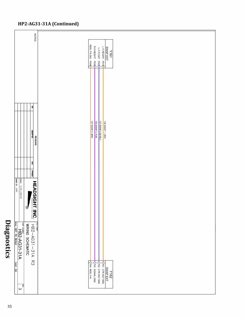
HP2-AG31-31A (Continued on next page)
35
Diagnostics
137 SWAP 2 D
k BLU
Y161SW
AP EXTP01
L H H
EIGH
T
P02L H
FLOAT
P03R
H H
EIGH
T
P04R
EEL F/A SIG
Y162SW
AP EXTP01
CTR
HG
T SNS
P02C
TR H
GT SN
S
P03SIG
NAL G
ND
P04R
EEL F/A
136 SWAP 1 O
RG
150 SWAP 3 PU
R
157 SWAP 4 BR
N
NO
TES:
HB2-AG
31-31A3
HP2-AG31-31A (Continued)

36
Diagnostics
Y101
INSI
GH
T
P11
HG
T SI
GN
AL
P18
TILT
IN L
OW
P16
TILT
SIG
NAL
P17
TILT
IN H
I
P412
V PO
WER
P6G
RO
UN
D
P2H
GT
SNS
V+
P3H
GT
SNS
GN
D
P7LE
FT H
GT
P8C
ENTE
R H
GT
P9R
IGH
T H
GT
QB5
-INPU
TH
ARN
ESS
050
SEN
SOR
PW
R P
NK
100
SEN
SOR
GN
D L
t BLU
087
RIG
HT
SEN
SOR
WH
T
084
CEN
TER
SEN
SOR
WH
T
081
LEFT
SEN
SOR
WH
T
Y302
FIEL
D T
RAC
KER A
TILT
REF
LO
W
BTI
LT S
IGN
AL
CTI
LT R
EF H
IGH
DSW
ITC
HED
12V
EG
RO
UN
D
303
TILT
IN A
Lt B
LUE
122
TILT
BAL
ANC
E G
REY
304
TILT
IN C
PIN
K
001
SIG
NAL
GN
D B
LK
012
12V
POW
ER
RED
301
HEI
GH
T A
Lt G
RN
125
HEI
GH
T SI
GN
AL W
HT
302
HEI
GH
TC
Lt G
RN
Y301
HEI
GH
TA
HG
T R
EF H
I
BH
EIG
HT
SIG
NAL
CH
GT
REF
LO
W
CR
IMP
AND
SO
LDER
R1
- 1k,
1 2 W
CR
IMP
AND
SO
LDER
R2
- 1K,
1 2 W
NO
TES:
QB3
-IH23
-XX
1
QB2-IH23-XX

37
Diagnostics
Y311C
OM
BINE
P27H
EADER
TYPE
P01LEFT H
GT
P03L C
HG
T
P04R
T C H
GT
P02R
IGH
T HG
T
P510V SU
PPLY
P6SIG
NAL G
RO
UN
D
P30C
HASSIS G
ND
P22LFT H
ZD LT
P28R
IGH
T HZD
LT
P24STU
BBLE LTS
P07R
EEL SPEED
P13SEN
SOR
GN
D
P20SW
AP 1
P26SW
AP 2
QB3-IN
PUT
HAR
NESS
001 SIGN
AL GN
D BLK
045 RIG
HT H
GT TAN
012 12V POW
ER R
ED
050 SENSO
R PW
R PN
K
100 SENSO
R G
ND
Lt BLU
087 RIG
HT SEN
SOR
WH
T
084 CEN
TER SEN
SOR
WH
T
081 LEFT SENSO
R W
HT
Y101IN
SIGH
T
P16H
EADER
TYPE
P10LEFT H
GT SIG
P11C
ENTER
HG
T SIG
P12R
IGH
T HG
T SIG
P412V PO
WER
P6G
RO
UN
D
P2H
GT SN
S V+
P3H
GT SN
S GN
D
P9R
IGH
T HG
T
P8C
ENTER
HG
T
P7LEFT H
GT
041 LEFT HG
T TAN
032 RIG
HT H
AZARD
Dk G
RN
033 STUBBLE LTS BR
N
031 LEFT HAZAR
D YEL
022 CH
ASSIS GN
D BLK
Y312H
EADER
P30C
HASSIS G
ND
P22LEFT H
ZD LT
P28R
IGH
T HZD
LT
P24STU
BBLE LT
P07R
EEL SPEED
P13SEN
SOR
V-
P20SW
AP 1
P26SW
AP 2
070 HEAD
ER TYPE YEL
136 SWAP 1 D
k BLU
137 SWAP 2 O
RG
098 REEL SPEED
GR
Y
101 SENSO
R G
ND
Lt BLU
043 CTR
HG
T TAN
043 CTR
HG
T TAN
NO
TES:
QB3-N
HC
R-31N
5
QB3-NHCR-31N
38
Parts
Parts
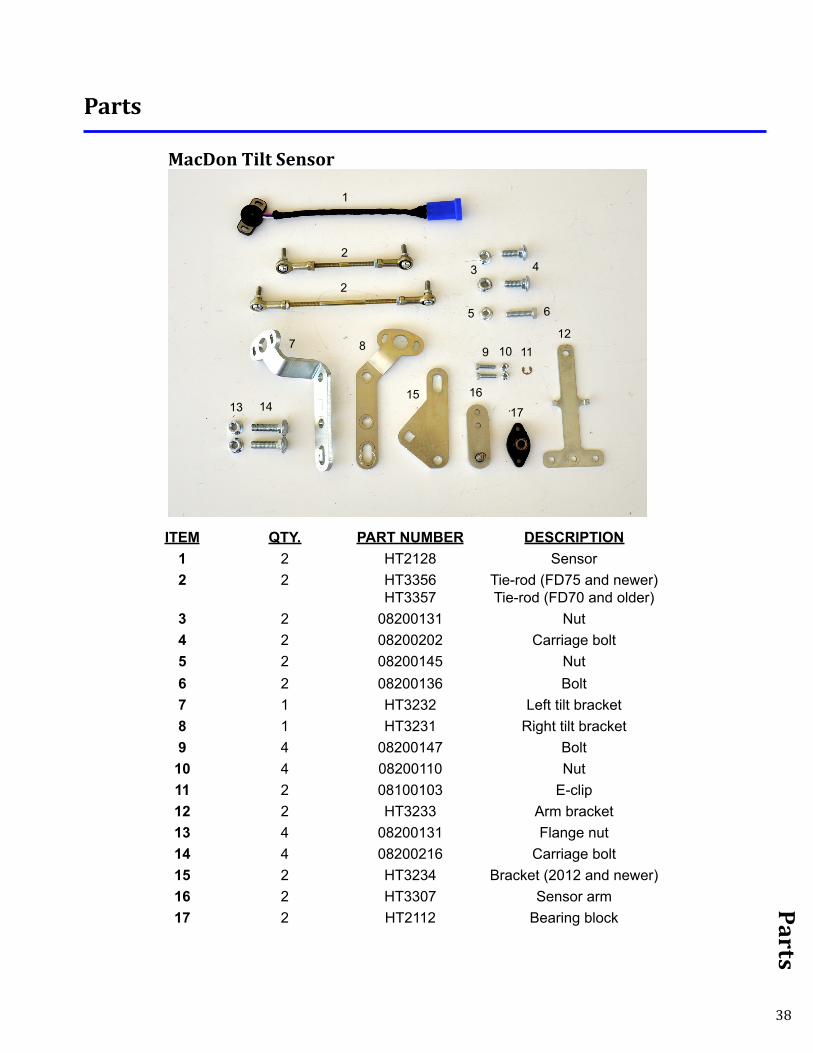
ITEM QTY. PART NUMBER DESCRIPTION1 2 HT2128 Sensor2 2 HT3356
HT3357Tie-rod (FD75 and newer)Tie-rod (FD70 and older)
3 2 08200131 Nut4 2 08200202 Carriage bolt5 2 08200145 Nut6 2 08200136 Bolt7 1 HT3232 Left tilt bracket8 1 HT3231 Right tilt bracket9 4 08200147 Bolt
10 4 08200110 Nut11 2 08100103 E-clip12 2 HT3233 Arm bracket13 4 08200131 Flange nut14 4 08200216 Carriage bolt15 2 HT3234 Bracket (2012 and newer)16 2 HT3307 Sensor arm17 2 HT2112 Bearing block
MacDon Tilt Sensor
1
243
13
7
1415
5
9 10 1112
6
8
2
16
17
39
Parts
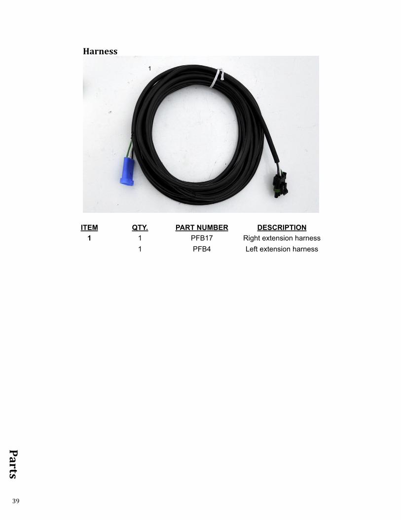
ITEM QTY. PART NUMBER DESCRIPTION1 1 PFB17 Right extension harness
1 PFB4 Left extension harness
Harness
1
2
3
STATEMENT OF LIMITED WARRANTY
For Headsight® Products Headsight Inc. (Headsight) warrants its new products to be free from defects in material and workmanship for a period of twelve (12) consecutive months following the date of purchase by the retail purchaser.
Headsight Inc. (Headsight) warrants its new corn sensors assemblies for a period of thirty-six (36) months.
Headsight warrants genuine Headsight replacement parts and components to be free from defects in material and workmanship for a period of six (6) consecutive months following the date of purchase or the remainder of the original equipment warranty period, whichever is longer.
Headsight’s obligation under these warranties shall be limited to repairing or replacing, free of charge to the original purchaser, any part that, in Headsight’s judgment, shows evidence of such defect.
Limitations to Warranty
This warranty does not cover:• Warranty claims directly resulting from improper installation of the product.• Any product damaged by accident, abuse, misuse, or negligence after shipment from Headsight.• Any unauthorized product alteration or modification.• Any unauthorized repairs made with parts other than genuine Headsight parts.• Any repairs performed by anyone other than Headsight or an authorized Headsight dealer unless specifically authorized
by Headsight.
Warranty Procedure• Troubleshooting should be done between farmer/dealer and Headsight through our technical assistance @
574.220.5511. • Labor reimbursement will occur only pre-arranged through Headsight technical assistance and be scheduled to a flat rate
basis or reasonable time allowance in Headsight’s judgment. • There is no mileage reimbursement. • Diagnostic time will not be reimbursed except in pre-arranged circumstances.• Warranty claims should be on typical dealer service work order with a number and name to be attached for any future
correspondence. • All warranty work must be performed, and claims submitted, within thirty (30) days of the occurrence of the claim and
within the warranty period.• All parts removed during warranty repair must be returned to Headsight with Headsight’s Return Form within thirty (30)
days of the occurrence of the claim and within the warranty period.• Headsight, Inc. reserves the right to either inspect the product at the original retail purchaser’s location or require it to be
returned to Headsight, Inc. for inspection.
Limitation of LiabilityHeadsight makes no express warranties other than those, which are specifically described herein. Any description of the goods sold hereunder, including any reference to buyer’s specifications and any descriptions in circulars and other written material published by Headsight is for the sole purpose of identifying such goods and shall not create an express warranty that the goods shall conform to such description.
THIS WARRANTY IS EXPRESSLY IN LIEU OF ALL OTHER WARRANTIES EXPRESSED OR IMPLIED. There are no implied warranties of merchantability or fitness of a particular purpose. This warranty states Headsight’s entire and exclusive liability and buyer’s exclusive remedy or any claim for damages in connection with the sale of furnishing of Headsight products, their design, suitability for use, installation or operation, or for any claimed defects herein. HEADSIGHT WILL IN NO EVENT BE LIABLE FOR ANY INCIDENTAL OR CONSEQUENTIAL DAMAGES WHATSOEVER, NOR FOR ANY SUM IN EXCESS OF THE PRICE RECEIVED FOR THE GOODS FOR WHICH LIABILITY IS CLAIMED.
No representative of Headsight nor any dealer associated with Headsight has the authority to change the items of this warranty in any manner whatsoever, and no assistance to purchaser by Headsight in the repair of operation of any Headsight product shall constitute a waiver of the conditions of this warranty, nor shall such assistance extend or revive it.
Headsight reserves the right to make improvements in design or changes in specifications at any time, without incurring any obligation to owners of units previously sold. Warranty: 1/2017

P 574.546.5022 • F 574.546.57604845 3B Rd • Bremen, IN [email protected]