
Tiffin Motorhomes, Inc. Powerglide Chassis Owner’s · PDF fileTiffin Motorhomes, Inc....
40
Tiffin Motorhomes, Inc. Powerglide Chassis Owner’s Guide 1 Tiffin PowerGlide Chassis Customer Support 256-356-0261 Monday-Friday 5 Days a week 7am-4:30pm CST If you should require chassis service, you should first contact your nearest Tiffin Powerglide Chassis service center. If for some reason this is not possible or if you would like to call the manufacturers direct, you can contact them at the following telephone numbers: TIFFIN POWERGLIDE CHASSIS 256-356-0261 (Please have your VIN# ready) COACH-NET (Nights and weekends) 1-866-590-5937 CUMMINS ENGINE COMPANY 1-800-DIESELS (800-343-7357) CATERPILLAR RV ENGINE SUPPORT 1-877-777-3126 ALLISON TRANSMISSIONS 1-800-524-2303 MICHELIN TIRE 800-TIRE-HELP (800-847-3435) Visit our web site at www.tiffinmotorhomes.com
Transcript of Tiffin Motorhomes, Inc. Powerglide Chassis Owner’s · PDF fileTiffin Motorhomes, Inc....

Tiffin Motorhomes, Inc.
Powerglide Chassis Owner’s Guide
1
Tiffin PowerGlide Chassis Customer Support
256-356-0261
Monday-Friday 5 Days a week
7am-4:30pm CST
If you should require chassis service, you should first contact your nearest Tiffin
Powerglide Chassis service center. If for some reason this is not possible or if you
would like to call the manufacturers direct, you can contact them at the following
telephone numbers:
TIFFIN POWERGLIDE CHASSIS
256-356-0261
(Please have your VIN# ready)
COACH-NET
(Nights and weekends)
1-866-590-5937
CUMMINS ENGINE COMPANY
1-800-DIESELS (800-343-7357)
CATERPILLAR RV ENGINE SUPPORT
1-877-777-3126
ALLISON TRANSMISSIONS
1-800-524-2303
MICHELIN TIRE
800-TIRE-HELP (800-847-3435)
Visit our web site at www.tiffinmotorhomes.com

Tiffin Motorhomes, Inc.
Powerglide Chassis Owner’s Guide
2
TIRE CARE
Maintaining the proper tire inflation pressure is the most important thing you can do to maximize the life of your tires. An under inflated tire will build up excessive heat that may go beyond the prescribed limits of endurance of the rubber and the radial cords. Over inflation will reduce the tire’s foot print on the road, reducing the traction, braking capacity, and handling of your vehicle. An over inflated tire will also cause a harsh ride, uneven tire wear, and will be more susceptible to impact damage.
Keep in mind that the pressure rating on the side wall of your tire is the maximum pressure for that tire. This is not necessarily the correct pressure for the tires when installed on your vehicle. Maintaining the correct tire pressure for your vehicle’s loaded weight is extremely important and must be a part of regular vehicle maintenance.
TIRE CARE What is the most important component of tire care?
TIRE PRESSURE o Why?
Improved Ride
Improved Tire Wear
Improved Road Handling
Improved Braking

Tiffin Motorhomes, Inc.
Powerglide Chassis Owner’s Guide
3
To determine the correct air pressure for your tires, load your motor home as you would normally travel, including water and fuel. Go to a truck scale as found at most major truck stops and weigh each wheel position independently, with driver and passenger(s) in the vehicle as described in the Michelin Recreational Vehicle Tire Guide (MWL43146 Rev. 6/07) to determine the correct air pressure for the weight on each wheel position. Then use the charts in the guide and adjust the pressure accordingly when the tires are cool or have not been driven for more than one mile. You may call 1-800-847-3435 for a copy of the Michelin Recreational Vehicle Tire Guide.
NOTE: Never reduce the air pressure in a hot tire.
REMEMBER: For control of your RV, it is critical that the tire pressure be the same on both sides of the axle.
Correct Tire Pressure
How to determine the correct pressure
Weigh each wheel position
Set tire pressure according to chart
* This Chart Shows Cold Inflation Pressures
295/80 R22.5 LRH Energy XZA2
Load per Wheel-end
PSI=> 70 75 80 85 90 95 100 105 110 Max Load per
Tire KPA=> 480 520 550 590 620 660 690 720 760
Single LBS 5,085
5,375
5,660
5,940
6,220
6,495
6,770
7,040
7,300
7,830
Dual LBS 9,020
9,530
10,030
10,530
11,030
11,510
12,000
12,470
12,950
6,940
Single KG 2,290
2,440
2,550
2,700
2,810
2,960
3,060
3,170
3,310
3,550
Dual KG 4,060
4,340
4,540
4,800
4,980
5,240
5,440
5,620
5,880
3,150

Tiffin Motorhomes, Inc.
Powerglide Chassis Owner’s Guide
4
Allison Transmission Operation Normal driving—best fuel economy
o Select ―D‖ and ―Mode On‖
Performance
o ―Mode Off‖
o For mountain driving select lower gears to maintain 2000+ engine RPM
Hill climbing on hot days
o Keep RPMs high to cool engine
Driving Tips with the Allison MD3060 3000MH Transmission:
The points at which shifts occur depend upon predetermined speeds and other operating conditions. A transmission ―shift calibration‖ includes several sets of shift points which may be used according to current or anticipated operating conditions, such as engine or transmission fluid temperature. Shift schedules may be changed using the MODE button.
The transmission control module (TCM) includes the capacity for two separate and distinct shift calibrations, one for use in ―Primary Mode‖ of operation and one in ―Secondary Mode.‖
Primary – This shift schedule is typically used for all normal vehicle operations.
Secondary – This is an alternate shift schedule that the TCM uses upon request. This is operator-controlled using the MODE button.
When you are driving under normal road conditions, the DRIVE mode is recommended for the best performance and fuel economy. The MODE switch should be set to ON for economy mode, but MODE off should be used when climbing hills and when extra performance is required.
The display screen on the shift control pad will indicate the highest selected gear for the transmission. When mountainous or up and down terrain conditions are encountered, you should manually select a lower gear, preferably lower than 5th gear, and turn OFF the mode switch. This can be done at any road speed by pressing the down arrow repeatedly until the desired gear is indicated in the window of the shifter pad and then pressing the MODE button. When your road speed decreases to a safe point, the transmission will downshift at a higher RPM than normal. This will decrease the use of overdrive while pulling hills, which can result in excessive heat build-up in the transmission, and it keeps the engine operating at peak horse power and performance.
When ascending a grade, maintain engine speed to within 400-500 RPM of governed engine speed. Governed speed will be 2000-2200 RPM depending on your engine model. Road speed may decrease, but the engine will be at its peak in the power curve.

Tiffin Motorhomes, Inc.
Powerglide Chassis Owner’s Guide
5
It is especially pertinent to monitor your water temperature gauge when climbing hills. Keep in mind; it is not uncommon for the temperature to rise, especially in hot weather. If the gauge reaches the end zone or if the temperature warning light on the gauge panel should come on, reduce your road speed and shift to the next lower gear and keep your tachometer within 500 RPM of engine governed speed. In many cases this will stabilize the water temperature. If the temperature gauge continues to rise, pull over to the side of the road and shift the transmission into neutral. Bring the engine RPM to 1,700—2,000 RPM until the temperature drops down into the normal range. This should occur in a relatively short period of time. If the temperature gauge does not begin to drop and stays in the red zone or continues to rise, shut down the engine and allow it to cool. After the engine is allowed to cool, check the fluid level in the reservoir and add a 50/50 coolant and water mixture if needed.
A good ―rule of thumb‖ for descending grades is to never use a higher gear than was used to climb the same or similar grade. Try to keep the engine within 500 RPM of governed speed. This will give the best engine braking and reduce the need to use the service brakes. Select a gear that will keep you at a safe speed with minimal brake application. Never ride your brakes when descending a grade since excessive brake heat will build up and your brakes could fade leaving you with little or no braking power.
If your vehicle is equipped with an exhaust brake, this will also assist in slowing your vehicle on a downhill grade. With the exhaust brake switch in the ON position, when your foot is released from the accelerator, the transmission select number changes to ―2.‖ The exhaust brake will engage and the transmission will begin to down shift as soon as road and engine speed will safely allow. This will produce a slowing effect and will remain engaged until either the exhaust brake switch is turned off, the accelerator is depressed, or the transmission shifts to second gear. If your initial speed is high, you may have to step on the brake to slow the vehicle before the transmission will down-shift from 6th gear to 5th gear. This is normal.
Always select (N) neutral on the transmission shift pad prior to turning off the vehicle engine.

Tiffin Motorhomes, Inc.
Powerglide Chassis Owner’s Guide
6
Allison Transmission
Fluid Level Check
Be sure transmission is at operating temperature (140° to 220° F)
Vehicle is parked on level ground
Transmission in neutral and engine at idle
Wait until vehicle has been stationary for two minutes
Simultaneously press the up and down arrow keys
Display indicates – OL
- ―OL followed by ―OK‖ indicates good oil level
- ―OL followed by ―HI‖ followed by number indicates quarts over- filled
- ―OL followed by ―LO‖ followed by number indicates quarts under-filled
- ―OL followed by ―--‖ proper conditions have not been met

Tiffin Motorhomes, Inc.
Powerglide Chassis Owner’s Guide
7
Brake System
Rear Brakes Automatic Slack Adjuster
Front brakes are 17” air applied disc
Rear brakes double as parking brake
- Park brakes are spring applied
- Two large 16.5 x 7‖ drum brakes
- Park brake remains applied even if air pressure is lost
If air pressure is lost
- A buzzer and warning lamp will alert you
Chassis is equipped with automatic slack adjusters
- No brake adjustment required
The rear brakes on the PowerGlide chassis are also used as the parking brakes. This provides you the holding power of two large drum brakes to prevent your coach from rolling even when fully loaded on a 20% grade.
A decrease in air pressure will not cause an immediate loss of brakes. If a leak develops in the air system while driving (at approximately 60 to 65 PSI) you will be alerted via a light on the instrument panel and an audible alarm. As you apply the brakes, the air supply holding the park brakes in the released position will gradually be depleted. When fully depleted (approximately 40 PSI to 45 PSI) the rear brakes will set. This allows you sufficient time to pull over to the side of the road.
NOTE: (The rear brakes have dual chambers—one for the service brakes and one for the park brake. The service brakes are air applied and spring released. The park brake is spring applied and air released).
The brake system is equipped with automatic slack adjusters that avoid the need to manually adjust your brakes. Each time you step on the brake pedal, if adjustment is needed, the adjusters will take up the slack.

Tiffin Motorhomes, Inc.
Powerglide Chassis Owner’s Guide
8
Compressed Air System
Tank Drains
The compressed air system is comprised of two air storage tanks. The primary tank stores and supplies air for the rear brakes, the secondary tank stores and supplies air for the front brakes.
When air is compressed it becomes hot. As it cools condensed moisture forms in the system. The air system is equipped with an air dryer to remove most of this moisture. The dryer has an automatic moisture ejector that releases the trapped moisture back into the atmosphere. However some moisture will form in the system beyond the dryer, and make its way into the storage tanks. As moisture collects in the primary and secondary tanks it displaces the area needed for air storage, thus requiring that the tanks be drained periodically.
The air system is equipped with two air tank drains conveniently located in the left rear storage compartment. One drain for the primary tank and one for the secondary tank. These drains should be opened daily for a few seconds to remove any moisture trapped in the tanks.

Tiffin Motorhomes, Inc.
Powerglide Chassis Owner’s Guide
9
.
Air Dryer
The Tiffin PowerGlide chassis air brake system features a Haldex Purest air dryer which removes the condensed moisture from compressed air. The air dryer is equipped with a desiccant cartridge that needs to be changed every 36 months. The dryer is located on the left hand frame rail (behind the rear axle).
WARNING: Air tanks should be bled of all pressure any time you perform work on the air system.

Tiffin Motorhomes, Inc.
Powerglide Chassis Owner’s Guide
10
Engine Compression
Brake
Provides:
Improved braking power
Reduces the chance of overheating brakes on steep grades
Works in conjunction with Allison electronic transmissions
Compression brake allows for 3 or 6 cylinder use
All brakes will build up heat when being used due to friction—this is normal. However, excessive use of the brakes when descending a grade can result in excessive heat and can cause ―brake fade‖ or a loss of braking power, even with disc brakes. The proper way to use your brakes is to go slowly enough that a fairly light occasional use of the brakes will keep your speed from increasing.
NOTE: DO NOT maintain continual brake pedal pressure when descending a hill with any type of brake system.
Rather, down shift the transmission to slow the vehicle and make light, intermittent brake applications to control downhill speeds. By utilizing the transmission gears and Compression Brake, continual use of the brakes will not be necessary. When using the transmission’s lower gears to slow the vehicle on hills, be careful not to exceed the governed speed of your engine. If engine-governed speed is exceeded, the transmission will shift up to the next range, rapidly increasing the speed of your vehicle. If you find that you are continually using the brakes to maintain a safe speed and to keep the RPM within this range, slow the vehicle down even further and shift the transmission to a lower gear.
CAUTION: DO NOT USE the Compression Brake on wet roads, hazardous, or slippery conditions. As with any motorized vehicle, practice safety when on the road.

Tiffin Motorhomes, Inc.
Powerglide Chassis Owner’s Guide
11
Scheduled Maintenance SERVICE INTERVAL
(Miles x 1,000) Daily 5 10 15 20 Required Fluids, Lubricants, and Procedures
Air System:
Air Dryer X Inspect for leaks and blockage of purge valve
Air Intake X Inspect for blockage
Air Filter X Check restriction indicator - replace filter as needed (7)
Primary Air Tank Reservoir X Drain condensation daily
Secondary Air Tank Reservoir X Drain condensation daily
Brake Systems:
ABS Sensors X Clean sensors & adjust into hub rings. (1)
Brake Pads, Rotors, Shoes & Drums X Inspect pads, shoes, rotors & drums for wear and cracks. (1)
Slack Adjusters X Inspect slack adjuster for proper adjustment & grease.
Brake Hoses/Whips, Front & Rear X Inspect for leaks, & cracking.
Cooling Systems:
A/C Condenser Fins X Inspect for blockage and wash clean every 10k or as needed
Charge Air Cooler Fins X Inspect for blockage and wash clean every 10k or as needed
Fan & Fan Shroud X Inspect for blockage and cracks.
Radiator Fins/Grill X Inspect for blockage and wash clean every 10k or as needed
Radiator Hoses & Pipes X Inspect for kinks, chaffing wear and leaks.
Surge Tank Cap X Inspect for leaks daily
Surge Tank Vent Lines X Inspect for kinks and leaks daily
Fan Clutch X Inspect for correct alignment
Fan Drive Belt X Replace fan belt.
Fan Drive Shaft U-Joints X Lubricate w/NGLI #2 grease
Fan Gear Box X Change fluid and inspect for leaks. (6)
Electrical Systems:
Rear Electrical Compartment X Check for loose fuses and cables
Front Electrical Compartment X Check for loose fuses and cables
Generator Cables X Check for loose red & black cables connected to generator
Alternator Belt X Check for correct tension and wear
Batteries X Check for loose lugs / remove any corrosion

Tiffin Motorhomes, Inc.
Powerglide Chassis Owner’s Guide
12
Scheduled Maintenance
SERVICE INTERVAL (Miles x 1,000)
Daily 5 10 15 20 Required Fluids, Lubricants, and Procedures
Engine Systems:
Engine Drive Belt Tension X Inspect belt & tension.
Engine Oil Filter X Replace engine oil filter per engine manual (1)
Engine Oil X Change engine oil per engine manual (1)
Exhaust Muffler & Piping X Inspect for pinholes, rust and leaks.
Diesel Fuel Always use ultra low sulfur fuel only
Fuel Tank Vent Lines X Inspect for "P" traps that may cause air locks and slow filling
Fuel Tank & Lines X Inspect for leaks around fuel inlet nipples and hoses.
Engine Coolant Change engine coolant per engine manual
Primary Fuel Filter X Replace fuel filter per engine manual (1)
Secondary Fuel Filter X Replace fuel filter per engine manual (1)
Steering Systems:
Drag Link X Inspect castle nuts for looseness & lube rod ends w/NGLI #2 grease
Steering Gear Arm X Inspect for looseness.
Steering Gear X Inspect mount bolts for looseness & hydraulic hoses for leaks.
Steering Gear Pump X Inspect for hydraulic hose leaks at fittings.
Steering Shaft U-Joints X Inspect for loose fasteners & lube bearings w/NGLI #2.
Steering Shaft Boot X Inspect for clearance between boot & shaft, lubricate w/ NGLI #2 grease.
Suspension & Axles:
Coach Alignment X Align coach as needed (4)
Front Ride Height Adjust X Adjust to 9" side to side from bottom of air bag to top of air bag mount place
Rear Ride Height Adjust X Adjust to 7" side to side from bottom of rail to centerline of axle
Ride Height Valve Linkages X Grease linkage grommets w/D.A. Stewart Aqualube.
Air Suspension Bags X Inspect for leaks at fittings and inspect bags for leaks or cracks
Front Axle Bearings X Check fluid level through sight window, if low, repair leaks as necessary (1)
Front Axle Tie Rods - Inspect X Inspect for looseness
Front Axle Tie Rods Lubricate X Lubricate W/NGLI # 2 grease
Front Axle King Pins X Lubricate W/NGLI #2 grease
Front & Rear Shocks X Inspect for leaks on shock tube, replace as needed
Rear Axle Lube X Inspect for leaks & check fluid level. Use synthetic oil only 75W90 (3)
Wheel Lug Torque X Re-torque all wheels nuts - Torque 450-500 lbs (2)

Tiffin Motorhomes, Inc.
Powerglide Chassis Owner’s Guide
13
Scheduled Maintenance
SERVICE INTERVAL
(Miles x 1,000) Daily 5 10 15 20 Required Fluids, Lubricants, and Procedures
Suspension & Axles:
Automatic Slack Adjusters X Lubricate W/NGLI #2 grease
Slack Adjuster Cam Shafts X Lubricate W/NGLI #2 grease
Slack Adjuster Clevis Pins X Inspect for wear in clevis pin and cotter pins. Replace as necessary
Transmission & Driveline:
Drive Shaft X Inspect u-joints & safety strap for loose bolts & wear, lubricate w/NGLI #2 grease
Transmission Fluid Replace fluid at 150,000 miles or 48 months whichever occurs first. (5)
Transmission Filters Replace filters at 75,000 miles or 36 months whichever occurs first. (5)
(1) Replace / inspect at stated mileage interval or every 12 months whichever occurs first
(2) Re-torque all wheel nuts after the first 100 miles, then every 10K miles thereafter.
(3) Factory filled with synthetic oil. Do not mix with mineral oils.
(4) For best tire life and handling, alignment of front axle is recommended every 15K miles.
(5) Factory filled with TranSynd. To maintain these service intervals, fluid must not be mixed with Dexron or other fluids.
(6) Total fluid capacity is 24oz. Use only synthetic 75W90 oil.
(7) Replace filter when indicator shows 25 inches or every two years whichever occurs first.

Tiffin Motorhomes, Inc.
Powerglide Chassis Owner’s Guide
14
Lubrication Points

Tiffin Motorhomes, Inc.
Powerglide Chassis Owner’s Guide
15
Lubrication Points

Tiffin Motorhomes, Inc.
Powerglide Chassis Owner’s Guide
16
Lubrication Points

Tiffin Motorhomes, Inc.
Powerglide Chassis Owner’s Guide
17
Lubrication Points

Tiffin Motorhomes, Inc.
Powerglide Chassis Owner’s Guide
18
Lubrication Points
NO. Components Remarks Total
1
ZF Independent Front Suspension Knuckle
Post
Two grease fittings; One on top & bottom of knuckle post, lubricate both sides of suspension
4
2 Knuckle Pins
Two grease fittings; one on top and one on bottom of knuckle pin. Lubricate both sides of suspension.
4
3
Height Control Linkage Pins
Two grease pins per Linkage Front and RearSuspension
8
4
Main Driveshaft Two grease fittings; lubricate both universal joints.
3
5
Automatic Slack Adjusters
One grease fitting on each slack adjuster. One adjuster on each side of the rear axle.
2
6
Rear Brake Camshaft Bracket
One grease fitting on each bracket; Pump in grease until it appears at the slack adjuster end of the bracket. Lubricate both sides of the rear axle.
2
8 Fan Driveshaft One grease fitting on slip joint.
1

Tiffin Motorhomes, Inc.
Powerglide Chassis Owner’s Guide
19
Maintenance Parts
Primary Fuel Filter / Water Sep W/ WIF sensor Fleetguard part # FS1003 Tiffin part # 31647 Secondary Fuel Filter Fleetguard part # FF5636 Engine Oil Filter Fleetguard part # LF9009 Engine Air Filter Parker / Racor # 094973007 Tiffin part # 30596
Alternator / AC Belt Gates part # K080755 Tiffin part # 5000139 Fan Drive Belt Carlisle part # RSVX-750-2 Tiffin part # 32306

Tiffin Motorhomes, Inc.
Powerglide Chassis Owner’s Guide
20
For assistance with your
Tiffin PowerGlide Chassis…
Please contact one of the following Chassis Specialists at Tiffin Motorhomes, Inc.
256-356-8661
Plant Manager
Gary Harris, extension 2288
Parts
Bobby Luther, extension 2382
Mechanical Engineer
Brad Warner, extension 2267
Electrical Engineer
Dennis Baldwin, extension 2363
Please have your Chassis VIN # ready when you call

Tiffin Motorhomes, Inc.
Powerglide Chassis Owner’s Guide
21
Pre-Trip Inspection
Check fluid levels & add as necessary
• Check tire inflation pressure
• Look for fluid leaks
Before starting your motor home daily, a few things must be checked. By doing so, you
ensure that a safe trip is in order and lessen your chances of experiencing difficulties while
on the road.
Check the tires for proper inflation pressure and any damage. Also check the inner duals. Refer to the air pressure charts in this manual for proper inflation pressures.
Look for fluid leaks under the motor home. This can prevent any serious problems from occurring later.
Check the coolant level in the reservoir and add a 50/50 mix of coolant and water if necessary. This reservoir can be found on the rear of your vehicle.
• Check SCA (supplemental coolant additive) and freeze point every 6 months or 25,000 miles. Recharge as required.
CAUTION: IF THE WATER TEMP IN YOUR ENGINE IS GREATER THAN 120 DEGREES, DO NOT REMOVE THE RADIATOR CAP! YOU COULD BE SEVERELY BURNED!
• Approximate COOLING SYSTEM CAPACITIES—does not include the heater core or other auxiliary systems added by coach manufacturer:
• Cummins ISL - Side Radiator 56 Qt. or 14 Gallons.
• Check transmission fluid level
• Check engine oil level
• Check for small animals in engine compartment like squirrels, and cats
Check the power steering fluid reservoir

Tiffin Motorhomes, Inc.
Powerglide Chassis Owner’s Guide
22
Pre-Trip Inspection
Check fuel/water separator ISC / ISL • Check fuel/water separator and drain any water or contamination that may be present.
After you have completed your inspection, you may now start your engine. Turn the key to the run position and wait for the wait to start light (in some cases it may read ―Inlet heater‖) to turn off. You may now start the engine. Never use ether or any other starting fluids to start the electronic engine. The inlet heater can ignite the fumes and cause an explosion in the air inlet system. Once you have started the engine, monitor your gauges carefully. Make sure that the oil pressure rises within 15 seconds. If it does not, shut down the engine and call a repair facility to determine the cause.

Tiffin Motorhomes, Inc.
Powerglide Chassis Owner’s Guide
23
Pre-Trip Inspection
Filter Restriction Indicator
• Check air filter restriction indicator Brand New Air Cleaner 10‖ to 12‖ of Vacuum
• Engine Air Cleaner Element should be changed when the air inlet restriction indicator reaches 25 inches of vacuum or every two years whichever occurs first.

Tiffin Motorhomes, Inc.
Powerglide Chassis Owner’s Guide
24
Instruments & Controls
Gauge and Warning Lamp Layout
WARNING LAMP
MODULE MASTER GAUGE
SPEEDOMETER
MESSAGE
CENTER
3-IN-1 GAUGE
4-IN-1 GAUGE

Tiffin Motorhomes, Inc.
Powerglide Chassis Owner’s Guide
25
Instruments & Controls
1. Tachometer 1. Oil Pressure Gauge 2. Low Fuel Warning Lamp 2. Oil Pressure Low Warning Lamp 3. Fuel Gauge 3. Front (Secondary) Air Press. Gauge 4. Low Battery Warning Lamp 4. Coolant Temperature Gauge 5. Voltmeter 5. High Temperature Warning Light 6. Rear (Primary) Air Press. Gauge
1. Speedometer 2. Message Center 3. Message Center ―m‖ Control 4. Message Center ―t‖ Control
1
3
4
5
2
1
2
3
5
6
4
1
4 3
2

Tiffin Motorhomes, Inc.
Powerglide Chassis Owner’s Guide
26
Instruments & Controls
Warning Lamp Module
1. Left Turn Indicator 2. Jacks Down Warning 3. Cruise Switch Status 4. Headlamp High Beam Indicator 5. Check Transmission Warning 6. Seat Belt Warning 7. Check Message Center 8. Right Turn Indicator 9. Check ABS Warning Light 10. Diesel Particulate Filter Indicator Lamp 11. Stop Engine Warning Lamp 12. Check Engine Warning Lamp 13. Park Brake Indicator 14. Low Air Warning Indicator 15. High Exhaust Temp Warning Lamp 16. Wait To Start Lamp
11
10
9
1 5 2 4 6 7 8
12
16
15
13
3
14

Tiffin Motorhomes, Inc.
Powerglide Chassis Owner’s Guide
27
Instruments & Controls
Message Center During normal operation the LCD displays the odometer value on the top line and a selected parameter on the second line.
DRIVE MODE - Display First Line First line display parameters are odometer and measurement unit selection. Speedometer can be set to read MPH or km/h by changing this selection. See section on settings and diagnostics.
Speedometer Setup - Units
Speedometer can be set to read MPH or km/h by changing this selection. See section on settings and diagnostics.
Odometer
The odometer function is always shown with key ON. It can be displayed on the LCD in miles or kilometers. The odometer reading can be displayed when the ignition switch is OFF by activating the gauge backlight.
DRIVE MODE - Display Second line Second line display parameters are selected by pressing the m button for less than 5 seconds. Pressing the m or t buttons displays a different parameter from the list.
The selected parameter is highlighted with reverse video (sample). The selected parameter is retained automatically after 5 seconds of inactivity; no further button presses are required. When the parameter is retained, the reverse video disappears.
1234.5 km km/h
20.3 km TRIP
1234.5 mi MPH
20.3 mi TRIP
FIRST LINE
SECOND LINE

Tiffin Motorhomes, Inc.
Powerglide Chassis Owner’s Guide
28
Instruments & Controls
Trip Odometer
* Metric version reads in km
Instantaneous Fuel Economy
*Metric version reads in L/100km
Average Fuel Economy
* Metric version reads in L/100km
Hourmeter
1234.5 mi MPH
20.3 mi TRIP
1234.5 mi MPH
20.3 mpg Inst F
1234.5 mi MPH
20.3 mpg Avg F
1234.5 mi MPH
67.8 hr

Tiffin Motorhomes, Inc.
Powerglide Chassis Owner’s Guide
29
Instruments & Controls
Idle Speed Adjustment When vehicle speed is 0, the cruise on/off switch is in the off position and the cruise control Set or Resume switch is pressed, the Idle Speed Adjust screen will display on the message center.
Idle speed is adjusted by using the Set & Resume or by using the message center control switches. The actual engine speed will be displayed as the adjustment is made. Once the Set or Resume switch has been released, there will be a 10 second delay in removing the Idle Speed Adjust screen from the LCD. The new idle speed will be retained in the engine control module as the default setting.
Settings and Diagnostic Screens The Settings and Diagnostic screens can only be accessed when the vehicle speed is equal to 0 mph and the display is in its normal operating (Drive Mode) screen. Pressing and holding the m button for longer than 5 seconds enables the Settings and Diagnostics menu.
Once in the Settings and Diagnostics menu, pressing the m or t buttons separately moves the reverse video highlight (example) up or down through the list, as indicated by the arrows. The highlighted item is selected when both m and t buttons are pressed at the same time. If no button is pressed for 5 seconds, the LCD will go back to the standard Drive Screen. The items available in the menu are:
Set Units
Enables the screen used to select if values are to be displayed in English or Metric units
IDLE SPEED
775 RPM m for + t for -
1-English/Metric Units
2-Contrast Adjust
3-Instrument Diagnostics
\/ Select /\
4-Engine Diagnostics
5-Transmission Diagnostic
6-ABS Diagnostics
\/ Select /\
7-Read Parameters
\/ Select /\
Current Units
ENGLISH
Press t for METRIC
Press m to exit
Current Units
METRIC
Press t for ENGLISH
Press m to exit

Tiffin Motorhomes, Inc.
Powerglide Chassis Owner’s Guide
30
Instruments & Controls
Contrast
Enables the screen used to set the LCD contrast. Pressing the m (+) button will increase contrast while pressing the t (-) button will decrease contrast. After 5 seconds of inactivity, the screen reverts back to the Drive Mode screen. The new contrast setting is written to memory upon returning to the Drive Mode screen.
Instrument Diagnostics Enables the screens used to perform diagnostic testing of the instrument system. Navigation through these menus is the same format as the main menu.
Gauge Test Each gauge pointer will be driven through three positions, pausing at each position for ½ second. The LCD shows the position of the pointer as a percentage of full scale. At the end of the test, the gauges revert back to their original pointer position and the program returns to the Instrument Diagnostics menu. When available, the warning light internal to the gauge will illuminate steady for the gauge being tested. Pressing the m button (Exit) will end the test and return to the Instrument Diagnostics menu. Sample LCD screens:
CONTRAST
+ -
1-Gauge Test
2-Lamp Test
3-LCD Test
\/ Select /\
4-Input Status
\/ Select /\
Fuel Level
EXIT 0%
Fuel Level
EXIT 50%
Fuel Level
EXIT 100%

Tiffin Motorhomes, Inc.
Powerglide Chassis Owner’s Guide
31
Instruments & Controls
Lamp Test Each warning bank light in the instrument panel that is controlled by the gauge network will be tested. This test does not test the actual light on the vehicle (vehicle load). Warning lights in the secondary gauges are not tested with this feature. They are tested during the Gauge Test diagnostic. At the start of the test, all warning bank lights are turned off. Each light is then toggled to the “on” state, and then “off”. The LCD displays the name of the light being tested and its status. At the end of the test, the lights revert back to their original state (on or off) and the program returns to the Instrument Diagnostics menu. Pressing the m button (Exit) will end the test and return to the menu. Sample LCD screens:
LCD Test Displays the ACTIA logo in normal and reverse video three times and then returns to the Instrument Diagnostics menu.
Inputs The module, pin number, and status of each input defined in the system are displayed for this test. Pressing the m button exits the test and returns to the menu. Pressing the t button scrolls the display to the next 4 inputs. For binary inputs, the value of “high” and “low” refer to the voltage level at the connector pin. This information is continuously updated to assist in troubleshooting
High Beam
EXIT ON
High Beam
EXIT OFF
Press t to Scroll
Press m to Exit
M-1 Fuel Level 85
M-4 Dimmer 8.4V
M-5 Service Brake High
M-6 Park brake High
M-11 Ignition High
M-12 Left Turn Low
M-13 Right Turn Low
M-14 Alarm in Low
WB-1 Cruise Enable High
WB-2 Cruise Set High
WB-3 Cruise Resume High
WB-4 Cruise Cancel High
WB-5 Chassis ID1 High
WB-8 Jacks Down High
Tiffin Motorhomes, Inc.
Powerglide Chassis Owner’s Guide
32
Instruments & Controls
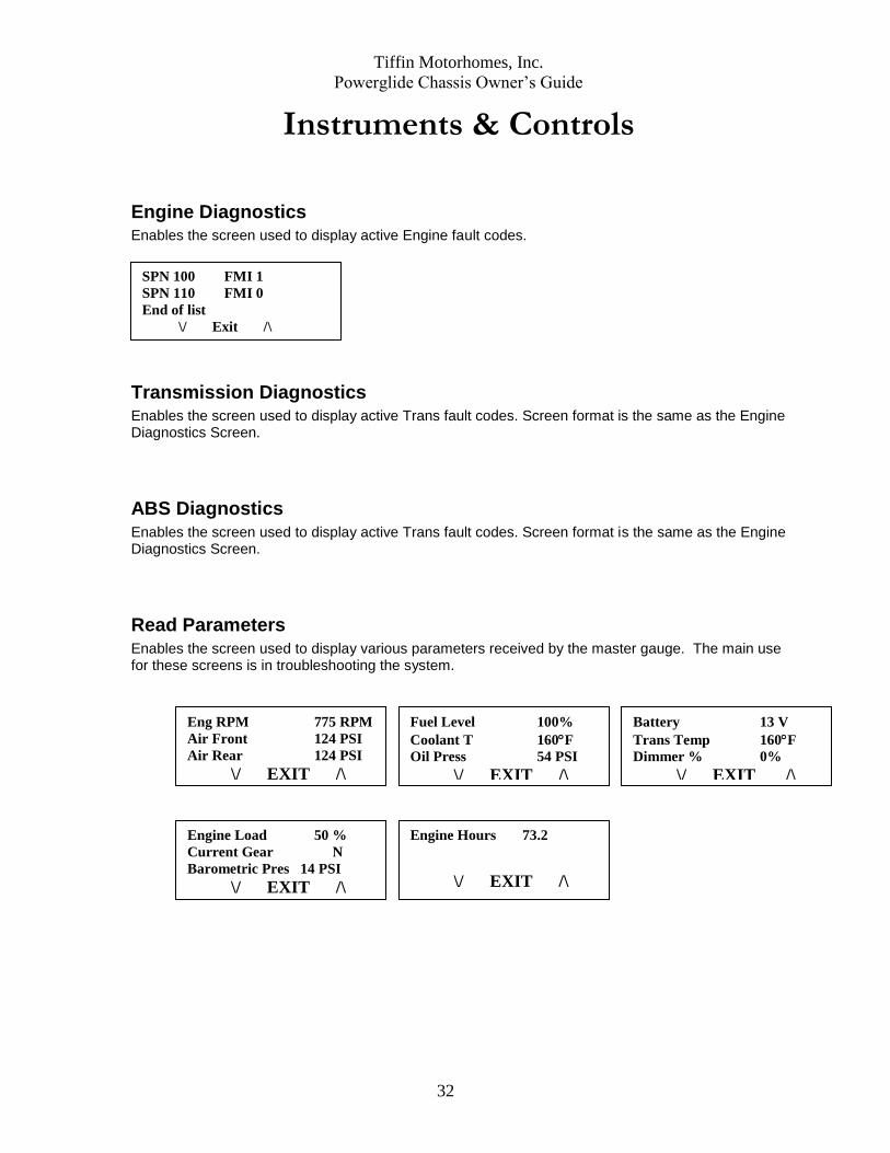
Engine Diagnostics Enables the screen used to display active Engine fault codes.
Transmission Diagnostics Enables the screen used to display active Trans fault codes. Screen format is the same as the Engine Diagnostics Screen.
ABS Diagnostics
Enables the screen used to display active Trans fault codes. Screen format is the same as the Engine Diagnostics Screen.
Read Parameters
Enables the screen used to display various parameters received by the master gauge. The main use for these screens is in troubleshooting the system.
SPN 100 FMI 1
SPN 110 FMI 0
End of list
\/ Exit /\
Eng RPM 775 RPM
Air Front 124 PSI
Air Rear 124 PSI
\/ EXIT /\
Fuel Level 100%
Coolant T 160F
Oil Press 54 PSI
\/ EXIT /\
Battery 13 V
Trans Temp 160F
Dimmer % 0%
\/ EXIT /\
Engine Load 50 %
Current Gear N
Barometric Pres 14 PSI \/ EXIT /\
Engine Hours 73.2
\/ EXIT /\

Tiffin Motorhomes, Inc.
Powerglide Chassis Owner’s Guide
33
Instruments & Controls
Setup Menu Pressing m and t while turning the ignition on enters the setup menu. Once in the Setup menu, pressing the m or t buttons separately moves the reverse video highlight (example) up or down through the list, as indicated by the arrows. The highlighted item is selected when both m and t buttons are pressed at the same time. If no button is pressed for 5 seconds, the LCD will go back to the standard Drive Screen.
Self Test
When YES is selected, the start up self test will zero the pointers, sound three tones from the speaker, sweep the gauge pointers through 50%, 100%, then back to zero, and turn all warning lights on for 5 seconds. When NO is selected the pointers will zero and all warning lights will be turned on for 5 seconds. Pressing t toggles between YES and NO, and pressing m exits back to the Setup Menu screen. The default setting for this is YES.
Cruise Switch Type
This selection changes how the master gauge interprets the three cruise control switch inputs. Upon entering this screen the present selection will be highlighted in reverse video. The operator is allowed to select the other method by pressing the t button. Selecting VIP will not be allowed if the binary input selecting the Rostra Stalk is hardwired low.
Self-Test Enabled?
YES
Press t to toggle
Press m to exit
Self-Test Enabled?
NO
Press t to toggle
Press m to exit
Cruise Switch Type
ROSTRA STALK
Press t to toggle
Press m to exit
Self-Test Enabled?
VIP SMART WHEEL
Press t to toggle
Press m to exit

Tiffin Motorhomes, Inc.
Powerglide Chassis Owner’s Guide
34
Instruments & Controls
SMARTWHEEL
GENERAL DESCRIPTION
The SmartWheel Steering Wheel offers control of the horn, headlamp and marker lamp flash,
cruise control, and wiper functions from switches mounted on the steering wheel. The system
consists of electronic switch pods attached to the wheel and the Control Module mounted in
the Front Junction Box. Communication between the steering wheel and the Control Module
is accomplished via four wires which utilize a clock-spring in the steering column as a
connecting path to allow for wheel rotation. As each switch is closed, the Switch Pod
generates a unique signal which is transmitted to the Control Module. The Control Module
decodes that signal to determine which switch is closed and operates the corresponding
outputs for that function. The same four wires provide power for back-lighting the steering
wheel switches.
1. HORN
Press horn pad on the steering wheel will send the appropriate signal to the Control Module
to cause the HORN output to be activated while the switch is pressed.
2. HEADLAMP FLASH
If the headlamps are turned on, pressing the switch will cause them to go off while the switch
is pressed. In like manner, if the headlamps are turned off, pressing the switch will cause
them to go on while the switch is pressed.
3. MARKER LAMP FLASH
If the marker lamps are turned on, pressing the switch will cause them to go off while the
switch is pressed. In like manner, if the marker lamps are turned off, pressing the switch will
cause them to go on while the switch is pressed.
2 3
1
4.4
4.3
4.2
4.1 5.1
5.2
5.3
5.4

Tiffin Motorhomes, Inc.
Powerglide Chassis Owner’s Guide
35
4. CRUISE FUNCTIONS:
4.1 CRUISE CANCEL
Operation of this switch signals the cruise system to disengage without losing the current
speed setting.
4.2 CRUISE RESUME
Operation of this switch actuates the Cruise Resume function of the engine controller.
4.3 CRUISE ON/OFF
Operation of this switch cycles the Cruise system from On to Off and back again. When
the switch is in the on position the green cruise indicator lamp will illuminate.
4.4 CRUISE SET
Operation of this switch actuates the Cruise Set function of the engine controller.
5. WIPER FUNCTIONS:
The wiper control functions are implemented through control circuit to VIP module.
5.1 WIPER OFF
Operation of this switch causes all operation of the wipers to be canceled. This mode is
also entered any time that the ignition is turned off.
Activation of any wiper function generates a "Headlamp On" signal from the Master
which will only be reset by turning off the ignition, or by activating, then deactivating the
dashboard headlamp switch.
5.2 WIPER WASH
Operation of this switch activates the wash pump relay while the switch is pressed. In
addition, if none of the latching wiper functions (Wiper Lo/Hi or Variable) had been
previously selected, the Low Speed Wiper will be activated for a period of approximately
3 wiper cycles after the switch is released. If any of the latching wiper functions (Wiper
Lo/Hi or Variable) had been previously selected, the wipers will continue to run in the
selected mode after the wash switch is released.
5.3 WIPER LO/HI
Operation of this switch initially causes the Low Speed Wiper function to activate. If the
switch is pressed again the High Speed Wiper function will be activated. Subsequent
presses of this switch will cause alternate operation of the wipers in the low or high speed
mode.

Tiffin Motorhomes, Inc.
Powerglide Chassis Owner’s Guide
36
5.4 WIPER VARIABLE
Operation of this switch initially causes the Low Speed Wiper function to activate for one
wipe. If the switch is pressed again within approximately 30 seconds, the Low Speed
Wiper function will be activated again and will repeat at an interval determined by the
time between the last two operations of the switch. Additional switch operations will
shorten the cycle. Activation of any other wiper mode cancels the variable mode. For
example, in light rain or mist conditions the driver presses the switch once when the
windshield first needs clearing. When the windshield again requires clearing the driver
presses the button again - setting the time period between subsequent wipes to that
required by current conditions.

Tiffin Motorhomes, Inc.
Powerglide Chassis Owner’s Guide
37
Air Supply
Front Cust. Air Supply Rear Customer Air Supply
• Manifold provided for auxiliary air source
- Up to 120 psi
- Quick connect fittings already installed at rear
• Can be used for:
– Air horn supply
– Fill tires
– etc.
The manifold is located in the left front electrical box. The customer quick connect fittings
are located in the left rear of the coach in the compartment labeled “Phone Jacks / TV
Cables.”
CAUTION: Air Tanks should be bled of all pressure before any work is done on the air
system!

Tiffin Motorhomes, Inc.
Powerglide Chassis Owner’s Guide
38
Warranty
Engine
o Cummins ISL 5 Years 100,000 mi
Transmission
o Allison 3000 MH Series 5 Years 200,000 mi
Chassis 3 Years 50,000 mi
Drive Train 3 Years 50,000 mi
Suspension 3 Years 50,000 mi
*All are completely transferable

Tiffin Motorhomes, Inc.
Powerglide Chassis Owner’s Guide
39
Allegro Owner’s Club
The Allegro Owner’s Club is an organization for Allegro motor home owners that provide
access to rallies and more. Several rallies are organized throughout the year. The rallies are
normally a package deal which includes your campground fees, entertainment, several meals,
transportation to and from planned activities, suppliers exhibits, plenty of door prizes, and
much more. Service technicians from Tiffin Motorhomes, Inc. are also available to do minor
repairs to rally participants motor homes as well as sales representatives who can answer
questions about your motor home and other issues. Of course, free time is scheduled into
each rally for your personal leisure and interests.
If you purchase a new unit, Tiffin Motorhomes pays for your first year of membership. Club
members are also eligible to purchase insurances at discounted rates as well as other
companies that provide discounts to our Club members.
Local chapters are also set up throughout the country. These local chapters generally have
monthly campouts which allow you to meet new friends and share information.
The Allegro Club also publishes a quarterly newsletter, Side Roads, which keeps members
informed about rallies, caravans, chapter news, safety information, factory news, and much
more. Side Roads is published in March, June, September, and December.
Allegro Club merchandise is also available at the Allegro Store in Red Bay, AL. You can
purchase shirts, caps, jackets, and other accessories emblazoned with the Tiffin name brands.
For more information on the Allegro Club or to join, please contact membership coordination
at 256-356-8522 or visit our web site: www.tiffinmotorhomes.com.

Tiffin Motorhomes, Inc.
Powerglide Chassis Owner’s Guide
40
Suggestions Please give us your suggestions on what you would like to see covered in this publication. These should be operation or maintenance items. When you have completed your suggestions mail them to Tiffin Motorhomes, 105 2nd Street NW, Red Bay, AL 35582. Attention: Gary Harris. Please Print:
_______________________________________________________
_______________________________________________________
_______________________________________________________
_______________________________________________________
_______________________________________________________
_______________________________________________________
_______________________________________________________
_______________________________________________________
_______________________________________________________
_______________________________________________________
_______________________________________________________
_______________________________________________________
_______________________________________________________
_______________________________________________________