Thrust Augmentation Measurements Using a Pulse … · Thrust Augmentation Measurements Using a ......
20
Robert J. Santoro and Sibtosh Pal Pennsylvania State University, University Park, Pennsylvania Thrust Augmentation Measurements Using a Pulse Detonation Engine Ejector NASA/CR—2003-212191 March 2003 https://ntrs.nasa.gov/search.jsp?R=20030033034 2018-07-19T09:44:13+00:00Z
Transcript of Thrust Augmentation Measurements Using a Pulse … · Thrust Augmentation Measurements Using a ......

Robert J. Santoro and Sibtosh PalPennsylvania State University, University Park, Pennsylvania
Thrust Augmentation Measurements Using aPulse Detonation Engine Ejector
NASA/CR—2003-212191
March 2003
https://ntrs.nasa.gov/search.jsp?R=20030033034 2018-07-19T09:44:13+00:00Z

The NASA STI Program Office . . . in Profile
Since its founding, NASA has been dedicated tothe advancement of aeronautics and spacescience. The NASA Scientific and TechnicalInformation (STI) Program Office plays a key partin helping NASA maintain this important role.
The NASA STI Program Office is operated byLangley Research Center, the Lead Center forNASA’s scientific and technical information. TheNASA STI Program Office provides access to theNASA STI Database, the largest collection ofaeronautical and space science STI in the world.The Program Office is also NASA’s institutionalmechanism for disseminating the results of itsresearch and development activities. These resultsare published by NASA in the NASA STI ReportSeries, which includes the following report types:
• TECHNICAL PUBLICATION. Reports ofcompleted research or a major significantphase of research that present the results ofNASA programs and include extensive dataor theoretical analysis. Includes compilationsof significant scientific and technical data andinformation deemed to be of continuingreference value. NASA’s counterpart of peer-reviewed formal professional papers buthas less stringent limitations on manuscriptlength and extent of graphic presentations.
• TECHNICAL MEMORANDUM. Scientificand technical findings that are preliminary orof specialized interest, e.g., quick releasereports, working papers, and bibliographiesthat contain minimal annotation. Does notcontain extensive analysis.
• CONTRACTOR REPORT. Scientific andtechnical findings by NASA-sponsoredcontractors and grantees.
• CONFERENCE PUBLICATION. Collectedpapers from scientific and technicalconferences, symposia, seminars, or othermeetings sponsored or cosponsored byNASA.
• SPECIAL PUBLICATION. Scientific,technical, or historical information fromNASA programs, projects, and missions,often concerned with subjects havingsubstantial public interest.
• TECHNICAL TRANSLATION. English-language translations of foreign scientificand technical material pertinent to NASA’smission.
Specialized services that complement the STIProgram Office’s diverse offerings includecreating custom thesauri, building customizeddatabases, organizing and publishing researchresults . . . even providing videos.
For more information about the NASA STIProgram Office, see the following:
• Access the NASA STI Program Home Pageat http://www.sti.nasa.gov
• E-mail your question via the Internet [email protected]
• Fax your question to the NASA AccessHelp Desk at 301–621–0134
• Telephone the NASA Access Help Desk at301–621–0390
• Write to: NASA Access Help Desk NASA Center for AeroSpace Information 7121 Standard Drive Hanover, MD 21076

Robert J. Santoro and Sibtosh PalPennsylvania State University, University Park, Pennsylvania
Thrust Augmentation Measurements Using aPulse Detonation Engine Ejector
NASA/CR—2003-212191
March 2003
National Aeronautics andSpace Administration
Glenn Research Center
Prepared under Grant NAG3–2657

Available from
NASA Center for Aerospace Information7121 Standard DriveHanover, MD 21076
National Technical Information Service5285 Port Royal RoadSpringfield, VA 22100
This report contains preliminaryfindings, subject to revision as
analysis proceeds.
The Propulsion and Power Program atNASA Glenn Research Center sponsored this work.
Available electronically at http://gltrs.grc.nasa.gov

NASA/CR�2003-212191 iii
TABLE OF CONTENTS
1. Introduction ........................................................................................................................... 1
2. Key Accomplishments in FY02 ............................................................................................ 1
2.1. Thrust Stand Description........................................................................................... 2
2.2. Thrust Measurements for 1.3 in. Diameter Detonation Tube ................................... 4
2.3. PDE-Ejector Setup .................................................................................................... 6
3. Measure of Technical Performance....................................................................................... 9
4. Proposed Schedule and Relative Progress ............................................................................ 10
5. Collaborations ....................................................................................................................... 10
6. Interactions with NASA Glenn Research Center�s PDE Research Program........................ 10
7. References ............................................................................................................................. 10
Appendix: PDE-Ejector Hardware........................................................................................ 11

NASA/CR�2003-212191 1
1. Introduction
Pulse detonation engine (PDE) technology is currently receiving a great deal of
consideration because of its potential for high efficiency combustion performance with reduced
hardware complexity [1-2]. Although most of the current research efforts are focused on
resolving the barriers to a pure PDE system, there are equally worthy options that involve the
incorporation of a PDE as a component in hybrid engine concepts. The present NASA GRC
funded three-year research project focuses on the study of a PDE driven ejector that would be
applicable to a hybrid Pulse Detonation/Turbofan Engine. The ejector would be intended for
applications that would replace the high-pressure compressor and high-pressure turbine sections
of the core of a high bypass turbofan engine. The objective of the present study is to characterize
the thrust augmentation achievable with a PDE-ejector and thus provide critical experimental
data from which to assess the performance enhancements possible with this technology.
The major potential advantages of the PDE-ejector as envisioned here include reduced
costs due to the elimination of expensive compressor and turbine components with resulting
reduced engine weight, along with improved specific fuel consumption and specific power
inherent in the incorporation of a PDE component. There is currently insufficient data on the
performance of such an ejector system to allow further development. Some of the key issues can
be resolved if suitable measurements of the thrust augmentation were available over a suitable
parameter space. Thus, at the present time the hybrid PD/Turbofan engine is at a Technology
Readiness Level (TRL) of 2 and the present research intends to increase PDE-ejectors to TRL 3
through the provision of critical experimental data that further defines the operational potential
of this novel technology.
The current research project on thrust augmentation experiments (NAG3-2657) was
officially awarded to Penn State on January 30, 2002. The progress made on the project during
the previous eight months in described in this report.
2. Key Accomplishments in FY02
The following tasks have been completed during the first eight months of the project.
• A thrust stand for measuring average thrust for multi-cycle operation of a detonation tube has
been designed and implemented.
• The average thrust for an existing 1.3 in. diameter detonation tube has been measured and
analyzed for ethylene as the fuel and a mixture of oxygen and nitrogen as the oxidizer.

NASA/CR�2003-212191 2
• Based on these initial measurements, a 2.25 in. diameter detonation tube has been designed
and fabricated as the driver for the PDE-ejector thrust measurement experiments.
The modular design of the system will allow experimentation to assess the effects of ejector
geometry (diameter, length and shape) on thrust augmentation. The ejector section for the
experiment has been designed and fabrication is near completion. Experiments will
commence in the very near future.
2.1. Thrust Stand Description
A thrust stand for measuring average thrust for multi-cycle operation of a detonation tube
has been designed and implemented. A schematic of the system is shown in Fig. 1. The thrust
stand features a solid table top on which the detonation tube is mounted on frictionless rails.
A thrust block with a spring (k=14.4. lbf/in.) is attached to the injector assembly end of the
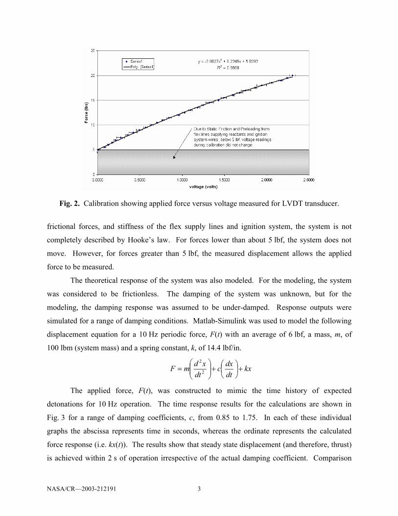
detonation tube. Calibration of the assembly was conducted by measuring the displacement of
the assembly for a range of forces. A force gage was used to supply a known force to the
system, whereas a linear voltage displacement transducer (LVDT) was used to measure the
displacement. The calibration curve for the system for the 1.3 in. diameter detonation tube
(described in the next section) is shown in Fig. 2. The calibration results show that due to
PDEFrictionless rails
Engine supports
Thrust springs
Thrust block
PDEFrictionless rails
Engine supports
Thrust springs
Thrust block
Fig. 1. Schematic of thrust stand setup.
NASA/CR�2003-212191 3
frictional forces, and stiffness of the flex supply lines and ignition system, the system is not
completely described by Hooke�s law. For forces lower than about 5 lbf, the system does not
move. However, for forces greater than 5 lbf, the measured displacement allows the applied
force to be measured.
The theoretical response of the system was also modeled. For the modeling, the system
was considered to be frictionless. The damping of the system was unknown, but for the
modeling, the damping response was assumed to be under-damped. Response outputs were
simulated for a range of damping conditions. Matlab-Simulink was used to model the following
displacement equation for a 10 Hz periodic force, F(t) with an average of 6 lbf, a mass, m, of
100 lbm (system mass) and a spring constant, k, of 14.4 lbf/in.
kxdtdxc
dtxdmF +
+
= 2
2
The applied force, F(t), was constructed to mimic the time history of expected
detonations for 10 Hz operation. The time response results for the calculations are shown in
Fig. 3 for a range of damping coefficients, c, from 0.85 to 1.75. In each of these individual
graphs the abscissa represents time in seconds, whereas the ordinate represents the calculated
force response (i.e. kx(t)). The results show that steady state displacement (and therefore, thrust)
is achieved within 2 s of operation irrespective of the actual damping coefficient. Comparison
Fig. 2. Calibration showing applied force versus voltage measured for LVDT transducer.

NASA/CR�2003-212191 4
with detonation tube firing results (presented later) indicates that the damping coefficient of the
system is about 1.5 lbf-s/in.
2.2. Thrust Measurements for 1.3 in. Diameter Detonation Tube
An existing detonation tube with an internal diameter of 1.3 in. was used for the initial
average thrust measurements. A picture of the detonation tube, the injector used for the setup
and a schematic showing high-frequency pressure transducer locations are shown in Fig. 4.
For these experiments, ethylene (C2H4) was used as the fuel and a mixture of oxygen and
nitrogen (O2+0.5N2) was used as the oxidizer. The equivalence ratio was targeted to be 1.1.
High speed Valvetek valves were used to control the injection timing. For the results discussed
next, 30-40 cycles at 10 Hz operation constituted a single firing. The fill time for each cycle was
set to be between 70-80 ms.
Pressure measurements made near the head end of the detonation tube (Port 1, Fig. 4(c))
using a high-frequency pressure transducer are shown in Fig. 5. The top graph shows the peak
pressures realized for individual detonations. The pressure traces for two consecutive detonation
events during the firing are magnified in the bottom section of the figure. These results are
typical of multi-cycle detonation tube operation.
Fig. 3. Calculated thrust response results. For each trace, the abscissa represents time (s), whereas the ordinate represents force response (lbf).

NASA/CR�2003-212191 5
The corresponding thrust response from the displacement measurements is shown in
Fig. 6. Results are shown here for two firings of 35 and 40 cycles, respectively. As mentioned
earlier, the system does not respond to forces less than about 5 lbf due to static friction and
preload from flex lines used for supplying propellants, and ignition system wiring. However, the
results show that the average thrust for the multi-cycle firing is reached within 2 s (i.e. 20 cycles)
of the start of the firing. Based on these average thrust measurements, the mixture based Isp for
the firing is about 130 s. Cooper et al. [3] carried out single-shot PDE thrust measurements for
the same propellant combination (i.e. C2H4, O2 and N2) using a pendulum mechanism. Their Isp
results for C2H4/(O2+0.33N2) and C2H4/(02+0.57N2) mixtures at an equivalence ratio of one are
162 and 150 s, respectively. The current results of Isp=130 s for C2H4/(02+0.5N2) at an
equivalence ratio of 1.1 agrees qualitatively with their results.
The thrust measurements described here for the 1.3 in. diameter detonation tube
demonstrates that steady state thrust can be accurately measured for multi-cycle operation of a
PDE or PDE-ejector system. In the next sub-section, the PDE-ejector system that has been
designed for this project is described.
TOP VIEW
30°
1.7mm
2.8mm
2.0mm
CROSS SECTION
Ø35.2mm
(a) Image of detonation tube (b) Impinging jet injector
1 2 63 54 7 8 9
Igniter
1.57m
Transducer Port
(c) Detonation tube schematic.
Fig. 4. Detonation tube used for average thrust measurements.

NASA/CR�2003-212191 6
2.3. PDE-Ejector Description
The existing 1.3 in. diameter detonation tube cannot be used for the PDE-ejector
experiments since the flanges and pressure ports would interfere with the ejector part of the
setup. Based on these considerations, design of a completely new PDE-ejector system was
Time [s]0.0 0.5 1.0 1.5 2.0 2.5 3.0 3.5
Rel
ativ
e Pr
essu
re [p
si]
0
100
200
300
400
500
600
Time [s]
0.878 0.879 0.880 0.881 0.882 0.883 0.884 0.978 0.979 0.980 0.981 0.982 0.983 0.984
Rel
ativ
e Pr
essu
re [p
si]
0
100
200
300
400
500
100 ms
Fig. 5. Pressure measurements near injector end of detonation tube.
Fig. 6. Thrust measurement results for two firings of 35 and 40 cycles, respectively.

NASA/CR�2003-212191 7
undertaken. A larger detonation tube with an inner diameter of 2.25 in. was chosen for this
geometry to increase the expected average thrust level (~18 lbf) at the same operating conditions
as described earlier (viz. 10 Hz operation with C2H4/(02+0.5N2) propellants at 1.1 equivalence
ratio). The higher thrust level will provide greater accuracy in the thrust measurement.
A schematic of the PDE-ejector design is shown in plate (a) of Fig. 7. A picture of the
fabricated detonation tube (ID and OD of 2.25 in. and 2.75 in., respectively) is also shown in the
same figure. Additional detailed drawings of the setup are included in the appendix. The tube is
six feet in length, with 3 ports located at 3 in. intervals in the center part for pressure transducer
instrumentation. Pressure transducers at these positions will be used to verify that detonations
occur in the main tube. Propellants for the detonation tube will be introduced through the
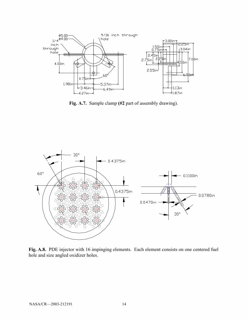
impinging jet injector shown in Fig. 8. Flow control will use four high-speed Valvetek valves,
two for oxygen, one for ethylene and one for nitrogen.
A metal stand welded to the detonation tube (Fig. 7(b)) provides rigidity to the system.
The detonation tube is bolted at the base of the stand to two frictionless sliders for thrust
(a)
(b)
Fig. 7. (a) PDE-ejector schematic, (b) Image of 2.25 in. diameter detonation tube.

NASA/CR�2003-212191 8
measurements as described earlier. The ejector shroud is a tube six feet in length, with a
diameter larger than that of the detonation tube. Three different diameter tube ejectors will be
tested. These 0.125 in. wall thickness tubes have outer diameters of 4 in., 5 in., and 6 in.,
respectively, and have ports in 6 in. intervals for high frequency pressure transducers.
The PDE-ejector system has been designed such that the detonation tube exit can be varied
within the ejector shroud. A clamp system has been designed to accommodate the different
diameter ejector shrouds. The design also features the capability of lateral positioning of the
ejector shroud, a feature that allows accuracy in concentric positioning of the detonation tube
with respect to the ejector shroud. The detonation tube and the ejector shroud are connected with
long bars that provide rigidity to the complete system. The thrust measurement device is a
rectangular bar with two free moving supports having a spring wrapped around each support.
All required hardware sections are currently in different stages of fabrication with
complete installation expected within 1 month. The new detonation tube fabrication is now
complete, and initial experiments will concentrate on characterizing the average thrust for PDE
engine only configuration. These experiments will be completed before the ejector shroud
hardware fabrication is complete.
(a) (b)
Fig. 8. Injector features 16 fuel-centered impinging jet elements. For each element, fuel is introduced through the central hole, whereas the oxidizer is introduced through six angled hole that impinge and mix rapidly with the central fuel jet. (a) Impinging jet injector face, (b) Central fuel tubes for injector.

NASA/CR�2003-212191 9
3. Measure of Technical Performance
The technical milestones for the first year of the project are included here (taken directly
from the proposal).
Year 1 (9/1/01 � 8/31/02) Cost :$100,000
Milestone 1: Determine the thrust for a stand alone 1.3-inch diameter detonation tube (2/28/02).
Milestone 2: Design and fabricate two ejector ducts for each PDE tube (2/28/02).
Milestone 3: Install and test 1.3-inch PDE in one of the two companion ejector ducts. Ducts will
be instrumented with high-speed pressure transducers (5/31/02).
Milestone 4: Complete thrust augmentation measurements for the 1.3-inch PDE-ejector tube in
one of the two ducts. (8/31/02).
Note that for the proposal, the expected start date was 9/1/01, whereas the actual start
date was delayed by 5 months (1/30/02). In short, Milestone 3 needs to be completed by
10/31/02. As discussed earlier, technical milestone 1 has been completed and milestones 2-3 are
near completion (within 1 month).
Table 1. Timeline and Milestones.
Year 1 Year 2 Year 3
Q1 Q2 Q3 Q4 Q1 Q2 Q3 Q4 Q1 Q2 Q3 Q4Measure thrust for det. tube (1.3 in.)
Des./Fab 2 ejector ducts
Install det. tube in 1st ejector duct
Measure thrust for det. tube/1st ejector
Install det. tube in 2nd ejector duct
Measure thrust for det. tube/2ndejector
Schlieren studies for straight nozzle indet. tube/duct assembly
Des./Fab optically-accessible section
Des./Fab det. tube conv. & div. nozzles
Schlieren studies for converging nozzlein det. tube/duct assembly
Schlieren studies for converging nozzlein det. tube/duct assembly
Final Report

NASA/CR�2003-212191 10
4. Proposed Schedule and Relative Progress
The timeline and milestones for the project is shown in Table 1 (taken from original
proposal). As is evident from the table and earlier discussion, the current progress is on track
with the proposed schedule.
5. Collaborations
Collaborations with Prof. Merkle of University of Tennessee have been on-going since
the start of the program. The PDE-ejector analysis performed by Prof. Merkle will help in
guiding the experiments for the full course of this three-year project.
6. Interactions with NASA Glenn Research Center�s PDE Research Program
The major interactions with the NASA Glenn PDE research program have resulted
through the periodic review meetings that have been held at NASA Glenn Research Center and
follow up discussions. In particular, interactions have occurred with Jack Wilson, Don Paxson
and Rene Fernandez. We have interacted with Jack Wilson in the area of fast actuating valves to
share experiences and supplier information as we are using different systems. Dan Paxson has
been very helpful in the area of the design of our ejector configuration in terms of comparison
with his modeling effort. In this respect, his work has impacted us more than us impacting work
at Glenn Research Center. Finally, discussions and interactions with Rene Fernandez led to his
participation in the conference (and Proceedings publication) of �Advances in Confined
Detonations� that was held last July in Moscow, Russia.
7. References
[1] Bratkovich, T., and Bussing, T., �A Pulse Detonation Engine Performance Model,� AIAA�
95�3155, 1995.
[2] Santoro, R., Broda, J., Conrad, C., Woodward, R., Pal, S., and Lee, S.-Y., �Multidisciplinary
Study of Pulse Detonation Engine Propulsion,� JANNAF, 36th CS/PSHS/APS Joint Meetings
(1999).
[3] Cooper, M., Jackson, S., Austin, J., Wintenberger, E., Shepherd, J. E., �Direct Experimental
Impulse Measurements for Detonations and Deflagrations,�" AIAA�01�3812 (2001).

NASA/CR�2003-212191 11
APPENDIX: PDE-Ejector Hardware In this appendix, PDE-ejector hardware drawings are included. The design features a PDE tube (2.25 in. diameter) with a multi-element (16) impinging jet injector. Modular design allows different size ejector tubes to be used for the experiments. Design also allows ejector tube positioning flexibility.
Fig. A.1. Assembly drawing of modular pulse detonation ejector system.
Fig. A.2. Detonation tube (2.25 in. diameter) for PDE-ejector experiments (#1 on assembly drawing).

NASA/CR�2003-212191 12
Fig. A.3. Constant diameter ejector tubes with pressure transducer ports (#3 on assembly drawing).
Fig. A.4. Connecting plate (#4 on assembly drawing).

NASA/CR�2003-212191 13
Fig. A.5. Adjustable stand for ejector tubes (#2 on assembly drawing).
Fig. A.6. Details of adjustable stand (#2 on assembly drawing).
NASA/CR�2003-212191 14
Fig. A.7. Sample clamp (#2 part of assembly drawing).
Fig. A.8. PDE injector with 16 impinging elements. Each element consists on one centered fuel hole and size angled oxidizer holes.

This publication is available from the NASA Center for AeroSpace Information, 301–621–0390.
REPORT DOCUMENTATION PAGE
2. REPORT DATE
19. SECURITY CLASSIFICATION OF ABSTRACT
18. SECURITY CLASSIFICATION OF THIS PAGE
Public reporting burden for this collection of information is estimated to average 1 hour per response, including the time for reviewing instructions, searching existing data sources,gathering and maintaining the data needed, and completing and reviewing the collection of information. Send comments regarding this burden estimate or any other aspect of thiscollection of information, including suggestions for reducing this burden, to Washington Headquarters Services, Directorate for Information Operations and Reports, 1215 JeffersonDavis Highway, Suite 1204, Arlington, VA 22202-4302, and to the Office of Management and Budget, Paperwork Reduction Project (0704-0188), Washington, DC 20503.
NSN 7540-01-280-5500 Standard Form 298 (Rev. 2-89)Prescribed by ANSI Std. Z39-18298-102
Form Approved
OMB No. 0704-0188
12b. DISTRIBUTION CODE
8. PERFORMING ORGANIZATION REPORT NUMBER
5. FUNDING NUMBERS
3. REPORT TYPE AND DATES COVERED
4. TITLE AND SUBTITLE
6. AUTHOR(S)
7. PERFORMING ORGANIZATION NAME(S) AND ADDRESS(ES)
11. SUPPLEMENTARY NOTES
12a. DISTRIBUTION/AVAILABILITY STATEMENT
13. ABSTRACT (Maximum 200 words)
14. SUBJECT TERMS
17. SECURITY CLASSIFICATION OF REPORT
16. PRICE CODE
15. NUMBER OF PAGES
20. LIMITATION OF ABSTRACT
Unclassified Unclassified
Annual Contractor Report
Unclassified
1. AGENCY USE ONLY (Leave blank)
10. SPONSORING/MONITORING AGENCY REPORT NUMBER
9. SPONSORING/MONITORING AGENCY NAME(S) AND ADDRESS(ES)
National Aeronautics and Space AdministrationWashington, DC 20546–0001
Available electronically at http://gltrs.grc.nasa.gov
March 2003
NASA CR—2003-212191
E–13794
WU–708–87–23–00NAG3–2657
21
Thrust Augmentation Measurements Using a Pulse Detonation Engine Ejector
Pulse detonation engine; PDE; Ejector
Unclassified -UnlimitedSubject Categories: 01 and 07 Distribution: Nonstandard
Pennsylvania State UniversityPropulsion Engineering Research Center andDepartment of Mechanical and Nuclear EngineeringUniversity Park, Pennsylvania 16802
Robert J. Santoro and Sibtosh Pal
Project Manager, Richard DeLoof, Aeropropulsion Research Program Office, NASA Glenn Research Center,organization code 0142, 216–433–6632.
The present NASA GRC-funded three-year research project is focused on studying PDE driven ejectors applicable to ahybrid Pulse Detonation/Turbofan Engine. The objective of the study is to characterize the PDE-ejector thrust augmenta-tion. A PDE-ejector system has been designed to provide critical experimental data for assessing the performanceenhancements possible with this technology. Completed tasks include demonstration of a thrust stand for measuringaverage thrust for detonation tube multi-cycle operation, and design of a 72-in.-long, 2.25-in.-diameter (ID) detonationtube and modular ejector assembly. This assembly will allow testing of both straight and contoured ejector geometries.Initial ejectors that have been fabricated are 72-in.-long-constant-diameter tubes (4-, 5-, and 6-in.-diameter) instru-mented with high-frequency pressure transducers. The assembly has been designed such that the detonation tube exit canbe positioned at various locations within the ejector tube. PDE-ejector system experiments with gaseous ethylene/nitrogen/oxygen propellants will commence in the very near future. The program benefits from collaborations with Prof.Merkle of University of Tennessee whose PDE-ejector analysis helps guide the experiments. The present research effortwill increase the TRL of PDE-ejectors from its current level of 2 to a level of 3.