Three-dimensional flows around low-aspect-ratio flat-plate wings at ...
21
J. Fluid Mech. (2009), vol. 623, pp. 187–207. c 2009 Cambridge University Press doi:10.1017/S0022112008005314 Printed in the United Kingdom 187 Three-dimensional flows around low-aspect-ratio flat-plate wings at low Reynolds numbers KUNIHIKO TAIRA† AND TIM COLONIUS Division of Engineering and Applied Science, California Institute of Technology, Pasadena, CA 91125, USA (Received 18 March 2007 and in revised form 4 November 2008) Three-dimensional flows over impulsively translated low-aspect-ratio flat plates are investigated for Reynolds numbers of 300 and 500, with a focus on the unsteady vortex dynamics at post-stall angles of attack. Numerical simulations, validated by an oil tow-tank experiment, are performed to study the influence of aspect ratio, angle of attack and planform geometry on the wake vortices and the resulting forces on the plate. Immediately following the impulsive start, the separated flows create wake vortices that share the same topology for all aspect ratios. At large time, the tip vortices significantly influence the vortex dynamics and the corresponding forces on the wings. Depending on the aspect ratio, angle of attack and Reynolds number, the flow at large time reaches a stable steady state, a periodic cycle or aperiodic shedding. For cases of high angles of attack, an asymmetric wake develops in the spanwise direction at large time. The present results are compared to higher Reynolds number flows. Some non-rectangular planforms are also considered to examine the difference in the wakes and forces. After the impulsive start, the time at which maximum lift occurs is fairly constant for a wide range of flow conditions during the initial transient. Due to the influence of the tip vortices, the three-dimensional dynamics of the wake vortices are found to be quite different from the two-dimensional von K´ arm ´ an vortex street in terms of stability and shedding frequency. 1. Introduction The Reynolds number at which micro-air-vehicles operate have reached O(10 4 ) and will continue to decrease in the coming years (Pines & Bohorquez 2006). Due to the operational and weight requirements, these aircraft have unique designs with low- aspect-ratio wings, when compared to those of the conventional aircraft. Moreover, these vehicles fly at low speed and often high angles of attack while experiencing large perturbations such as wind gusts. Yet there are only few studies of low-Reynolds- number aerodynamics around low-aspect-ratio wings under translation. As micro-air-vehicles become smaller in size, they share some characteristics with flying and swimming animals such as birds, insects and fishes. These animals have low-aspect-ratio wings or fins that are operating at Reynolds numbers of order 10 2 to 10 5 , often at post-stall angles of attack. However, separated flows have been used to the advantage of the animals for enhanced performance. For example, it has been observed that hovering insects can achieve added lift from the unsteady † Present address for correspondence: Department of Mechanical and Aerospace Engineering, Princeton University, Princeton, NJ 08544, USA. Email: [email protected].
Transcript of Three-dimensional flows around low-aspect-ratio flat-plate wings at ...

J. Fluid Mech. (2009), vol. 623, pp. 187–207. c© 2009 Cambridge University Press
doi:10.1017/S0022112008005314 Printed in the United Kingdom
187
Three-dimensional flows around low-aspect-ratioflat-plate wings at low Reynolds numbers
KUNIHIKO TAIRA† AND TIM COLONIUSDivision of Engineering and Applied Science, California Institute of Technology,
Pasadena, CA 91125, USA
(Received 18 March 2007 and in revised form 4 November 2008)
Three-dimensional flows over impulsively translated low-aspect-ratio flat plates areinvestigated for Reynolds numbers of 300 and 500, with a focus on the unsteadyvortex dynamics at post-stall angles of attack. Numerical simulations, validated by anoil tow-tank experiment, are performed to study the influence of aspect ratio, angleof attack and planform geometry on the wake vortices and the resulting forces onthe plate. Immediately following the impulsive start, the separated flows create wakevortices that share the same topology for all aspect ratios. At large time, the tipvortices significantly influence the vortex dynamics and the corresponding forces onthe wings. Depending on the aspect ratio, angle of attack and Reynolds number, theflow at large time reaches a stable steady state, a periodic cycle or aperiodic shedding.For cases of high angles of attack, an asymmetric wake develops in the spanwisedirection at large time. The present results are compared to higher Reynolds numberflows. Some non-rectangular planforms are also considered to examine the differencein the wakes and forces. After the impulsive start, the time at which maximum liftoccurs is fairly constant for a wide range of flow conditions during the initial transient.Due to the influence of the tip vortices, the three-dimensional dynamics of the wakevortices are found to be quite different from the two-dimensional von Karman vortexstreet in terms of stability and shedding frequency.
1. IntroductionThe Reynolds number at which micro-air-vehicles operate have reached O(104) and
will continue to decrease in the coming years (Pines & Bohorquez 2006). Due to theoperational and weight requirements, these aircraft have unique designs with low-aspect-ratio wings, when compared to those of the conventional aircraft. Moreover,these vehicles fly at low speed and often high angles of attack while experiencing largeperturbations such as wind gusts. Yet there are only few studies of low-Reynolds-number aerodynamics around low-aspect-ratio wings under translation.
As micro-air-vehicles become smaller in size, they share some characteristics withflying and swimming animals such as birds, insects and fishes. These animals havelow-aspect-ratio wings or fins that are operating at Reynolds numbers of order102 to 105, often at post-stall angles of attack. However, separated flows have beenused to the advantage of the animals for enhanced performance. For example, ithas been observed that hovering insects can achieve added lift from the unsteady
† Present address for correspondence: Department of Mechanical and Aerospace Engineering,Princeton University, Princeton, NJ 08544, USA. Email: [email protected].

188 K. Taira and T. Colonius
separated flows around the flapping wings. The leading-edge vortices are found to bestably attached throughout each stroke and provide additional spanwise circulationresulting in enhanced lift. Such forces applied by the unsteady vortex formation in two-dimensional flows were investigated both experimentally by Dickinson & Gotz (1993)and numerically by Wang (2000a ,b, 2004) and Bos et al. (2008). Furthermore, the fullthree-dimensional studies drawing attention to spanwise flows and tip effects aroundthe flapping wings were undertaken experimentally by Ellington et al. (1996), Birch &Dickinson (2001), Usherwood & Ellington (2002), Birch, Dickson & Dickinson(2004) and Poelma, Dickson & Dickinson (2006). Analogous numerical studies wereperformed by Liu & Kawachi (1998) and Sun (2005).
Similar investigations have been carried out to analyse the efficient locomotion ofswimming animals. In particular, von Ellenrieder, Parker & Soria (2003), Buchholz &Smits (2006) and Parker, von Ellenrieder & Soria (2007) have visualized the wakevortices behind flapping low-aspect-ratio hydrofoils to understand the qualitativedynamics. Numerical simulations of the three-dimensional flows over flapping foilswere also performed by Blondeaux et al. (2005) and Dong, Mittal & Najjar (2006)at Reynolds numbers similar to the present study. Moreover, Drucker & Lauder(1999) have experimentally visualized the flows around pectoral fins and Zhu et al.(2002) have performed simulations around an entire fish to identify the wakestructures.
For purely translating low-aspect-ratio wings, Torres & Mueller (2004) haveexperimentally measured the aerodynamic characteristics of low-aspect-ratio wingsat Reynolds numbers around 105. Aerodynamic performance (lift, drag, pitchingmoment, etc.) of various planforms was considered over angles of attack (α) of 0◦–40◦ and aspect ratios (AR) of 0.5–2 and was observed to be quite different fromthat of low-aspect-ratio wings in high-Reynolds-number flows. They concluded thatthe most important parameter that influences the aerodynamic characteristics is theaspect ratio. Transient studies have also been conducted by Freymuth, Finaish &Bank (1987) by using smoke to visualize the start-up flows around low-aspect-ratio airfoils. A qualitative insight into the three-dimensional formation of wakevortices was presented. The experiments by Ringuette, Milano & Gharib (2007)extensively studied the wake vortices behind low-aspect-ratio plates but only atα = 90◦.
On the numerical side, two-dimensional simulations around translating wings wereperformed by Hamdani & Sun (2000). Also, studies by Mittal & Tezduyar (1995)and Cosyn & Vierendeels (2006) considered the three-dimensional flows aroundtranslating low-aspect-ratio planforms but focused mostly on those at low anglesof attack. For wings at post-stall angles of attack, unsteady separated flows andvortex dynamics behind low-aspect-ratio wings in pure translation are still not welldocumented.
To extend the previous studies, we use numerical simulations to examine theaerodynamics of impulsively started low-aspect-ratio flat-plate wings under puretranslation at Reynolds numbers of 300 and 500. These Reynolds numbers are highenough to induce separation and unsteadiness in the wake but low enough for thethree-dimensional flow field to remain laminar. The regime also includes, for a rangeof angles of attack, the critical Reynolds numbers at which the flow first becomesunstable to small disturbances. In the following section, we present the numericalmethod and its validation. In § 3, results from separated flows around the airfoils arepresented. We call attention to the transient nature of the flow field and its influenceon the aerodynamic forces. The stability of the wake at large time is also investigated.

Flows around low-aspect-ratio wings 189
Dynamics of the wake vortices and the corresponding lift and drag are consideredover a range of angles of attack and for various planform geometries.
2. Simulation methodology2.1. Numerical formulation
Three-dimensional incompressible flow over a low-aspect-ratio flat-plate wing issimulated with an immersed boundary method (Peskin 2002; Mittal & Iaccarino2005; Taira & Colonius 2007). With this method, a body of arbitrary geometry canbe generated in a flow field by adding a boundary force to the momentum equation.The continuous analogue of the immersed boundary formulation can be representedby the following non-dimensional incompressible Navier–Stokes equations:
∂u
∂t+ u · ∇u = −∇p +
1
Re∇2u +
∫s
f (ξ (s, t)) δ(ξ − x) ds, (2.1)
∇ · u = 0, (2.2)
u(ξ (s, t)) =
∫xu(x)δ(x − ξ ) dx = uB(ξ (s, t)), (2.3)
where u, p and f are the appropriately non-dimensionalized velocity, pressure andsurface force. The temporal variable is reported in terms of the non-dimensionalconvective time unit (i.e. U∞t/c). The spatial variables in the computational domainD and along the immersed boundary ∂B (in this case, surface of the plate) are denotedby x and ξ , respectively, and are normalized by the mean chord of the plate. Reynoldsnumber is defined as Re ≡ U∞c/ν, where U∞, c and ν denote the free-stream velocity,mean chord length of the plate and kinematic viscosity of the fluid, respectively.The velocity vector (non-dimensionalized by the free-stream velocity) is set to uB , theimmersed boundary velocity, along ∂B.
In later discussions, forces on the flat plate (Fx, Fy, Fz) are described in termsof the non-dimensionalized lift, drag and side forces defined by CL = Fy/(
12ρU 2
∞A),
CD = Fx/(12ρU 2
∞A) and CS = Fz/(12ρU 2
∞A), respectively, where ρ is the density of thefluid and A is the area of the flat plate. In the case of two-dimensional flows, theforce per unit span is normalized by the chord.
In the current work, we employ a particular immersed boundary method called theimmersed boundary projection method developed by Taira & Colonius (2007). Thismethod enforces both the incompressibility and no-slip constraints through a singleprojection in a manner similar to the projection utilized to satisfy incompressibility inthe traditional fractional-step methods. Equations (2.1)–(2.3) are spatially discretizedthrough a second-order finite-volume formulation on a staggered grid. The convectiveand viscous terms are integrated in time with the second-order Adams–Bashforth andthe Crank–Nicolson schemes, respectively. Further details on the method can befound in Taira & Colonius (2007) and Taira (2008).
2.2. Simulation setup
Simulations are performed in a large rectangular box typically of size[−4, 6.1] × [−5, 5] × [−5, 5] in the streamwise (x), vertical (y) and spanwise (z)directions. Typical grid size ranges from 125 × 55 × 80 to 200 × 88 × 128 with thesmallest resolution of �x = 0.025 for the case of AR = 2 and much larger sizes wereused for simulations of flows around higher aspect ratio plates. Grid stretching isapplied in all directions with finer resolution near the plate to capture the wakestructure as illustrated in figure 1. Extensive studies have been performed in two and

190 K. Taira and T. Colonius
y
z x
Figure 1. A typical computational domain showing the top-port side of the wake around arectangular flat plate of AR = 2. The spatial discretization of this computational domain isshown for every five cells for the x- and y-directions and four cells for the z-direction.
three dimensions to ensure that the present choice of grid resolution and domain sizedoes not influence the flow field in a significant manner (previously reported in Tairaet al. 2007 and Taira 2008).
Boundary conditions along all sides of the computational boundary ∂D are set touniform flow (U∞, 0, 0) except for the outlet boundary where a convective boundarycondition (∂u/∂t + U∞∂u/∂x =0) is specified. Inside the computational domain, aflat plate is positioned with its centre at the origin. This flat plate is instantaneouslymaterialized at t = 0+ in an initially uniform flow to model an impulsively startedtranslating plate. Computations are advanced in time with a time step such that theCourant number based on the free-stream velocity obeys U∞�t/�x � 0.5. Both theinitial transient and the large-time behaviour of the flow are considered.
2.3. Validation
We compare results from the three-dimensional simulations and measurements froman oil tow-tank experiment of flows over a rectangular plate of dimension 82 mm ×164 mm × 3 mm (AR = 2). The experiment is performed in a tank (2.4 m × 1.2 m ×1 m) filled with a blend of Chevron Superla R© white oil, Texaco Corporation. Therectangular flat plate is translated in the tank while being rigidly mounted to a six-axisforce sensor at one-wing tip to limit lift due to backlash in the gearbox. This setupis attached to a translation sled equipped with a servomotor providing control of thetranslational velocity (Dickson & Dickinson 2004). A constant translation velocity ismaintained by the plate after a swift acceleration from rest. The temperature in thelaboratory is regulated at 18 ± 1◦C such that there is less than 5% variation in thekinematic viscosity (ν = 115cSt). The variation in the translational velocity is much lessthan that of the viscosity, with the presence of the velocity control mechanism. Hence,the Reynolds number with estimated variation is Re =U∞c/ν =100 ± 5. During theexperiments, the flow field is captured with stereo digital particle image velocimetry(DPIV).
Shortly after the initial transient, the flow achieves a steady state at this lowReynolds number. Due to the spatial setup of the oil tank, the maximum traveldistance of the plate is limited to 13 chord lengths to avoid the interference ofwall effects. In figure 2, snapshots of the spanwise vorticity (ωz) contour are shownfor the simulation (with a grid size of 150 × 66 × 96) and experiment for the plate

Flows around low-aspect-ratio wings 191
1 t = 1.5
0
Exp
erim
ent
y
–1–1 0 1
1 t = 7.5
0
–1–1 0 1
1 t = 13
0
543210
–1–2–3–4–5–1
–1 0 1
1
0
Sim
ulat
ion
y
–1–1 0
x x x1
1
0
–1–1 0 1
1
0
–1–1 0 1
Figure 2. Snapshots of spanwise vorticity field at mid-span around a plate of AR =2 atα = 30◦ from the experiment and the simulation. Free stream is directed from left to right andthe position of the plate is illustrated with the black solid line (for the experiment, the positionis approximate due to the deflection of the plate). The boxed regions in the simulated resultsrepresent the fields of view for the DPIV measurements.
at α = 30◦. Following the impulsive start, the leading- and tailing-edge vortices areformed (t = 1.5). Later in time, the trailing-edge vortex (starting vortex) detaches andthe leading-edge vortex moves upward. At this low Reynolds number, the vorticityprofile is very diffusive and the vorticity generated at the leading and tailing edgesforms a smeared steady distribution. This flow profile is reached by t =7.5 and isindistinguishable from the last snapshot taken from the experiment at t = 13. As itcan be seen from figure 2, the simulated flow field is in good agreement with theDPIV measurements. Three-dimensional flow past a plate of AR = 2 is found to reacha stable steady state due to the stabilizing effects from the tip vortices and viscosity.We note in passing that the analogous two-dimensional flow at Re = 100 exhibitsperiodic shedding of the leading- and trailing-edge vortices.
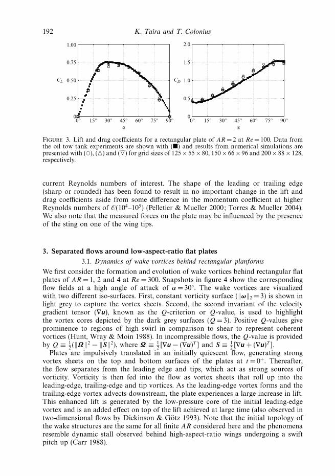
For the purpose of validating our simulation, we also compare lift and drag forces att = 13 from both the simulation and experimental measurements. It is found from thesimulation that, past t = 13, forces decay to the steady value in a very slow manner.Figure 3 compares measured lift and drag coefficients with the simulations basedon three different grid sizes for α ∈ [0◦, 90◦]. It can be observed that the two caseswith finer grid sizes of 150 × 66 × 96 and 200 × 88 × 128 are almost indistinguishable.Similar grid resolution studies are performed for the cases investigated in the presentpaper.
Lift coefficients from experiments and simulations are in agreement over the fullrange of α. Drag coefficients show slight discrepancy between the experiment andthe numerical computation, due to the thickness of the flat plate. In experiments,the thickness of the plate is 0.037c, while in the simulations, we attempt to modelan infinitely thin plate with regularized body forces dependent on the grid spacing.However, the flow features are insensitive to our selection of grid spacing at the
192 K. Taira and T. Colonius
CL
015°0°
00°30° 45°
α
60° 75° 90° 15° 30° 45°α
60° 75° 90°
0.25
0.50
0.75
1.00
CD
0.5
1.0
1.5
2.0
Figure 3. Lift and drag coefficients for a rectangular plate of AR = 2 at Re = 100. Data fromthe oil tow tank experiments are shown with (�) and results from numerical simulations arepresented with (�), (�) and (�) for grid sizes of 125 × 55 × 80, 150 × 66 × 96 and 200 × 88 × 128,respectively.
current Reynolds numbers of interest. The shape of the leading or trailing edge(sharp or rounded) has been found to result in no important change in the lift anddrag coefficients aside from some difference in the momentum coefficient at higherReynolds numbers of O(104–105) (Pelletier & Mueller 2000; Torres & Mueller 2004).We also note that the measured forces on the plate may be influenced by the presenceof the sting on one of the wing tips.
3. Separated flows around low-aspect-ratio flat plates3.1. Dynamics of wake vortices behind rectangular planforms
We first consider the formation and evolution of wake vortices behind rectangular flatplates of AR = 1, 2 and 4 at Re = 300. Snapshots in figure 4 show the correspondingflow fields at a high angle of attack of α =30◦. The wake vortices are visualizedwith two different iso-surfaces. First, constant vorticity surface (‖ω‖2 = 3) is shown inlight grey to capture the vortex sheets. Second, the second invariant of the velocitygradient tensor (∇u), known as the Q-criterion or Q-value, is used to highlightthe vortex cores depicted by the dark grey surfaces (Q = 3). Positive Q-values giveprominence to regions of high swirl in comparison to shear to represent coherentvortices (Hunt, Wray & Moin 1988). In incompressible flows, the Q-value is providedby Q ≡ 1
2(‖Ω‖2 − ‖S‖2), where Ω ≡ 1
2[∇u − (∇u)T ] and S ≡ 1
2[∇u + (∇u)T ].
Plates are impulsively translated in an initially quiescent flow, generating strongvortex sheets on the top and bottom surfaces of the plates at t = 0+. Thereafter,the flow separates from the leading edge and tips, which act as strong sources ofvorticity. Vorticity is then fed into the flow as vortex sheets that roll up into theleading-edge, trailing-edge and tip vortices. As the leading-edge vortex forms and thetrailing-edge vortex advects downstream, the plate experiences a large increase in lift.This enhanced lift is generated by the low-pressure core of the initial leading-edgevortex and is an added effect on top of the lift achieved at large time (also observed intwo-dimensional flows by Dickinson & Gotz 1993). Note that the initial topology ofthe wake structures are the same for all finite AR considered here and the phenomenaresemble dynamic stall observed behind high-aspect-ratio wings undergoing a swiftpitch up (Carr 1988).

Flows around low-aspect-ratio wings 193
AR = 1 AR = 2 AR = 4
t = 1
.5t =
5.0
t = 1
0.0
t = 1
5.0
t = 2
0.0
t = 4
0.0
Figure 4. Top-port views of the wake vortices behind rectangular plates of AR = 1, 2 and 4at α = 30◦ and Re = 300. Shown are the iso-surface of ‖ω‖2 = 3 in light grey with vortex coreshighlighted by the iso-surface of Q = 3 in dark grey.

194 K. Taira and T. Colonius
As features from the initial transient lose their effect on the plate through advectionand diffusion, the wake behind the plate becomes strongly dependent on the aspectratio. At α = 30◦, the AR = 1 case slowly reaches a steady state with a pair of strongcounter-rotating tip vortices that cover the entire span of the plate. The vortex sheetcreated from the leading edge is kept attached to the plate due to the downwardinduced velocity from the tip vortices.
For a plate of AR = 2, the vortex sheet emanating from the leading edge rolls intoa leading-edge vortex that accumulates spanwise vorticity over time. The tip vorticesare not strong enough to keep the leading-edge vortex attached. Around t ≈ 8, twoconsecutive leading-edge vortices start to pinch off from the plate. As the detachmenttakes place, the disconnected vortices start to interact with the tip vortices. Thisinteraction results in the loss of the columnar structures initially maintained by thetip vortices and reduces the downward induced velocity onto the vortical structureresiding above the top surface of the plate. Hence, once the initial leading-edgevortices are separated, consecutive formation of the leading-edge vortices (hairpinvortices) by the roll-up of the leading-edge vortex sheet occurs farther and at a higherposition. Additionally, weakening of the tip vortices allows the trailing-edge vortexsheet to morph into hairpin vortices that shed. The nonlinear interaction of the wakevortices results in an unsteady aperiodic flow at large time. While it is not apparentfrom figure 4, there is slight asymmetry in the spanwise direction that contributes tothe aperiodic nature of the shedding. Discussion on this asymmetry is offered later in§ 3.4.
For the largest finite aspect-ratio plate considered (AR = 4), the weaker influenceof the tip vortices across the span results in more strongly pronounced periodicshedding of the leading- and trailing-edge vortices. The shedding frequency (non-dimensionalized as the Strouhal number with the frontal projection of the chord)for AR = 4 is found to be St ≡ f c sinα/U∞ = 0.12. In contrast, the two-dimensionalshedding frequency for the same Reynolds number and angle of attack is St = 0.16.
Around AR = 3, the vortical structures from the leading and trailing edges start toseparate into two cells across the span. The cellular pattern referred to as stall cellsbecomes more apparent for AR = 4 where a pair of hairpin vortices are generatedfrom the leading edge and another pair is created from the trailing edge resultingin a release of four hairpin vortices per shedding cycle. Such flow features were alsoreported on the top surface of the airfoils with oil film and tuft visualizations byWinkelmann & Barlow (1980) and Yon & Katz (1998), respectively, at Re = O(105).While we do not notice features of the stall cells directly on the top surface, we findqualitative agreement for the number of cells observed some short distance into thewake.
Despite the interactions between the leading-edge and tip vortices, these vorticesremain distinct without merging for all three-dimensional cases. Due to the existenceof the right-angled corners on the rectangular plates, the vortex sheets thin outnear these regions and the sheets roll up into individual core structures of leading-edge and tip vortices. The separation of the vortical structures indicates a lack ofconvective vorticity flux in the spanwise direction (i.e. from the mid-span to the tips).Such transport has been suggested to stabilize the leading-edge vortex for flappingwings (Birch & Dickinson 2001; Birch et al. 2004). For the translating rectangularwings, there is no mechanism to relieve the vorticity being fed into the leading-edgevortex other than diffusion and shedding of the vortical structures. The effects ofremoving sharp corners by using different planform geometries are discussed later in§ 3.5.

Flows around low-aspect-ratio wings 195
t = 1
.0t =
1.5
t = 2
.0
t = 2
.5t =
3.0
t = 3
.5
Figure 5. Top views of the wake vortices behind a rectangular wing of AR = 2 at α = 40◦
from smoke visualizations at Rea = 5200 and present results at Re =500 with iso-contour of‖ω‖2 = 5. Smoke visualizations are from Freymuth et al. (1987); reprinted by permission ofthe American Institute of Aeronautics and Astronautics.
3.2. Flows at higher Reynolds number
Flows behind rectangular plates at Re = 500 are also simulated and are found to besimilar to the ones presented here for Re = 300. With the larger Reynolds number,the wake vortices are less diffused but the topology of the vortical structure arequalitatively similar, which was also noted by Dong et al. (2006) for flows aroundflapping foils for Re = 100–1000.
The geometries of the wake vortices in low-Reynolds-number flow (Re = O(100)) atearly times following the impulsive start also resemble those in flows of much higherReynolds numbers, due to the fact that the viscous time scale (tvis ∼ c2/ν) is muchlarger than the time scale associated with advection or acceleration (tadv ∼ c/U∞ ortacc ∼ c1/2/a1/2, respectively).
Impulsive flow over a plate of AR =2 at Re = 500 and α = 40◦ is simulated and iscompared to the smoke visualizations of vortices under a constant acceleration fromquiescent flow in a starting wind tunnel (Freymuth et al. 1987) as shown in figure 5.Reynolds number for this experiment is defined with the constant acceleration,the chord and the kinematic viscosity as Rea = a1/2c3/2/ν = 5200 following the non-dimensionalization by Freymuth et al .
As acceleration of immersed boundaries contributes to the generation of vorticity(Hornung 1989), the formation of vortices behind a plate under impulsive translationand constant acceleration cannot be directly compared. However, the formationof start-up vortices should be qualitatively similar at early times before viscouseffect significantly influences the flow and the induced velocity of each wake vortexbecomes large. The formation of the start-up vortices is illustrated by the snapshots infigure 5 with smoke visualization and the vorticity norm iso-surface.
For the case of constant acceleration, a characteristic velocity of ua = a1/2c1/2 isused to non-dimensionalize the temporal variable. Accordingly, the flow fields arecompared at the non-dimensional times of tU∞/c and ta1/2/c1/2 for the simulationsand the experiments, respectively. In figure 5, it can be seen that the formationand evolution of leading-edge and tip vortices are in good agreement between the

196 K. Taira and T. Colonius
experiment and the numerical solution despite the difference in the Reynolds numberand the velocity profile to which the plate is subjected. The exact location of thetrailing-edge vortex from the smoke visualization is difficult to pinpoint but is foundto be in accord by its faint trail of smoke at earlier times. The simulation is ableto capture even the thin layer of vortex sheet emanating from the leading edge,which would correspond to the region directly downstream of the leading edge thatis not visualized by the smoke. Dominant flow features at early times in high-Reynolds-number flows are captured even with the present low-Reynolds-numberflow simulations.
3.3. Force exerted on the plate
Unsteady forces on accelerating airfoils at low Reynolds numbers have beenconsidered for two-dimensional flows by Dickinson & Gotz (1993) and Pullin &Wang (2004). In this section, we consider the forces exerted upon the plate with thethree-dimensional wake vortices both immediately after the impulsive start and alsoat large times.
Representative lift and drag on rectangular plates from the present simulations arepresented in figure 6 for Re = 300. Here results for angles of attack of α ∈ [0◦, 60◦]and aspect ratios of 2 and 4 as well as the two-dimensional cases are shown fort ∈ [0, 70]. At t = 0+, the impulsive start imposes infinite acceleration on the airfoil inthe streamwise direction and results in infinite initial drag (not shown for graphicalclarity). Subsequently, lift starts to increase as accumulation of spanwise vorticityinstigates the formation of the leading-edge vortex. This increase in lift continues toabout t ≈ 1.7 to reach its maximum. The time to reach maximum lift is observed tobe fairly constant in the case of finite aspect ratio wings over most of the angles ofattack considered here at low Reynolds numbers. The universality of this number isdiscussed in detail later on.
After the initial start-up, lift is reduced by as much as half of the maximum valueat large time, as shown in figure 6. Depending on whether the wake at large timebecomes steady or unsteady, the corresponding force coefficients reach constant orfluctuating values.
It should be noted that the three-dimensional flows under consideration are vastlydifferent from the two-dimensional case, where one observes periodic shedding ofthe leading- and trailing-edge vortices creating the von Karman vortex street. Dueto the absence of the tip vortices, the two-dimensional flow exerts a strikingly largerfluctuation in force per unit span as shown in figure 6.
The effect of aspect ratio on the forces is considered by comparing the maximumlift during the transient and the time-averaged forces at large time. These values forwings of AR = 1, 2 and 4, as well as the two-dimensional case, are presented in figure 7accompanied by their inviscid limits. Stronger influence of downwash from the tipvortices results in reduced lift for lower aspect-ratio plates. For the limiting case oftwo-dimensional flow, the maximum lift is much higher due to the absence of tipeffects (figure 7a). It is interesting to note that the maximum lift achieved soon afterthe impulsive start is comparable or higher than the three-dimensional inviscid limitfor low-aspect-ratio straight wings in incompressible flow (Helmbold 1942):
CL =2πα√
1 + (2/AR)2 + 2/AR. (3.1)
This limit is derived from the lifting surface theory for elliptic wings and is shownto be in remarkable agreement with wings of AR < 4. Lift for rectangular wings of

Flows around low-aspect-ratio wings 197
AR
= 2
CL
10 20 30 40 50 60 70 0 10 20 30 40 50 600
1
2
3
CD
10 20 30 40 50 60 70 0 10 20 30 40 50 600
1
2
3
tα
AR
= 4
CL
10 20 30 40 50 60 70 0 10 20 30 40 50 600
1
2
3
CD
10 20 30 40 50 60 70 0 10 20 30 40 50 600
1
2
3
CL
10 20 30 40 50 60 70 0 10 20 30 40 50 600
1
2
3
CD
10 20 30 40 50 60 70 0 10 20 30 40 50 600
1
2
3
tα
Tw
o-di
men
sion
al
Figure 6. Force history on rectangular flat plates of different AR for a range of anglesof attack at Re = 300. Lift and drag coefficients are shown on the left and right panels,respectively.
0.5 � AR � 6.0 is accurately predicted with this equation as shown in Anderson(1999).
We observe agreement between the time-averaged low-Reynolds-number lift atlarge time and the above inviscid model at low angles of attack (α � 10◦), wherethe flows are still attached (figure 7b). The difference at low angles of attack can beattributed to viscous effects. However, once the flow separates from the plate at higherα, the inviscid approximation is no longer able to model the lift behaviour. The highvalue of αCL max (angle of maximum lift) was also reported for low-aspect-ratio wingsat Re ∼= 105 by Torres & Mueller (2004). We mention that the difference between themaximum (max CL) and the average (avg CL) lifts is the lift enhancement generatedby the initial leading-edge vortex.

198 K. Taira and T. Colonius
max
CL
0° 10° 20° 30° 40° 50° 60° 0° 10° 20° 30° 40° 50° 60°
0° 10° 20° 30° 40° 50° 60°
0
0.5
1.0
1.5
2.0
2.5(a) (b)
(c) (d )
avg
CD
0° 10° 20°α α
30° 40° 50° 60°0
0.5
1.0
1.5
2.0
2.5
0
0.5
1.0
1.5
2.0
2.5
3.0
AR = 1AR = 2
AR =
42D
avg
CL
0
0.5
1.0
1.5
2.0
2.5
AR = 1
AR = 2AR =
42D
avg
(CL/C
D)
Figure 7. Characteristic coefficients for rectangular plates at Re = 300: (a) maximum lift; (b)time-averaged lift coefficient at large time; (c) time-averaged drag coefficient at large time and(d ) time-averaged lift-to-drag ratio at large time for AR = 1 (�), AR = 2 (�), AR = 4 (�) andtwo-dimensional (�). Overlaid are the two- ( ) and three-dimensional ( ) inviscid liftlimits.
The average drag values at large time (avg CD) for pre-stall angles of attack increasewith decreasing aspect ratio (figure 7c). However for higher angles of attack, dragcoefficients are significantly smaller for finite-aspect-ratio wings in contrast to theirtwo-dimensional analogue. It is interesting to note that both average lift and dragcoefficients become larger past α = 20◦ for AR = 2 wings than those of AR = 1, mostlikely due to the difference in the behaviour of the wake at large time (discussed laterin § 3.4).
At Re = 300, the viscous stress has a significant influence on the drag experiencedby the wing, especially at low angles of attack. In comparison, at Re = 105 and AR =1,Torres & Mueller (2004) report CD = 0.025 and 0.11 for α = 0◦ and 10◦, respectively.At α = 15◦, CD = 0.24 is recorded by Torres and Mueller, a value close to what ismeasured in the current study also (figure 7c). Hence, we argue that past this angleof attack, pressure drag is the main cause of drag.
Shown also in figure 7(d ) are the average lift-to-drag ratios at large timeavg (CL/CD), which are larger for higher aspect-ratio wings. The ratios peak at higherangles of attack for low aspect-ratio plates. While the two-dimensional avg (CL/CD)reaches its maximum around α = 10◦, that of AR = 1 is achieved near α = 20◦. Thismay suggest favourable operating conditions at higher angles of attack for the low-aspect-ratio wings. For high angles of attack (α > 40◦), the lift-to-drag ratio fordifferent aspect ratios coalesce to the same value.

Flows around low-aspect-ratio wings 199
t∗t∗
0° 10° 20° 30°α
40° 50° 60°0
1
2
3
4(a)
0 1 2 3
20
40
t∗
0° 10° 20° 30°α
40° 50° 60°0
1
2
3
4(b)
0 1 2 3
20
40
Figure 8. Time at which lift achieves the maximum, t∗, after an impulsive start for differentangles of attack at (a) Re =300 and (b) Re = 500. Symbols denote cases for AR = 1 (�),AR =1.5 (�), AR = 2 (�), AR =3 (�), AR = 4 (�) and two-dimensional (�). The mean averagesare shown with solid lines. The inset figures are the corresponding histograms.
While it is not shown in this section, forces measured at Re =500 are found to bequantitatively and qualitatively similar to those at Re = 300. Interesting differencesbetween the two Reynolds numbers are observed in the stability of the wake, whichis described later in § 3.4.
Next, we call attention to the time at which the maximum lift is achieved. We denotethis time by t∗ and present its value in figure 8 for Re = 300 and 500. It is foundthat, for the considered aspect ratios and angles of attack, t∗ is fairly constant around1.7 (a value between 1.25 and 2.25) because the profiles of the leading-edge vorticesare similar among all cases. As the accumulation of spanwise vorticity generatedby the leading edge contributes to the growth of the leading-edge vortex, there isreminiscence to the formation number used to describe the time at which vortex ringscan no longer grow larger in strength (Gharib, Rambod & Shariff 1998). Since theformation number is found to be a universal quantity for a variety of flows (e.g.Jeon & Gharib 2004; Milano & Gharib 2005), it is not surprising that t∗ is alsofairly constant for the three-dimensional cases considered here. In the case of thetwo-dimensional flow, we observe a wider range of t∗ between 1.3 and 2.4 for α < 45◦.At higher α, a second local maximum starts to emerge for the two-dimensional flowlowering t∗ significantly.
The side force (Fz) remained zero for all cases that reached steady or periodicunsteady flows. However, for aperiodic flow cases observed at high angles of attack,the wake became asymmetric about the mid-span and exerted side forces uponthe plate. These unsteady side forces were an order of magnitude smaller than thedominant lift and drag forces experienced by the plate. For all cases considered inthis paper (later summarized in figure 10), it was observed that side forces have smallmagnitudes of |CS | = |Fz/(
12ρU 2
∞A)| < 0.02. The genesis of these side forces is discussedin the next section.
3.4. Large-time behaviour and stability of the wake
Here, we consider the behaviour of the wake behind rectangular plates at largetime. After the initial transient generated by the impulsive start settles down, thewake reaches one of the three states: (i) a stable steady state, (ii) a periodicunsteady state or (iii) an aperiodic unsteady state. Examples from each one ofthese states were presented in § 3.1. In this subsection, we consider a wide range

200 K. Taira and T. Colonius
00.1 0.2 0.3 0.4
010
2030
4050
0.005
0.010
0.015
0.020
St = fc sinα/U∞
Power
Aperiodic
Periodic(St = 0.12)
α
Figure 9. Power spectra of the lift trace for a rectangular plate of AR = 3 in flows ofRe = 500 at various angles of attack.
AR
0° 10° 20° 30°α α
40° 50° 60°1
2
3
4
2D(a)
Steady Unsteady
PeriodicAperiodic
(asymmetric)
0° 10° 20° 30° 40° 50° 60°1
2
3
4
2D(b)
Unsteady
PeriodicAperiodic
(asymmetric)
Steady
Figure 10. Stability of the wake for a range of α and AR at (a) Re = 300 and (b) Re =500.Symbols (�), (�) and (�) denote steady, unsteady periodic and unsteady aperiodic wakes atlarge time. The shaded area and the dashed line approximately represent the region of stabilityand the transition from periodic to aperiodic shedding, respectively. Shown at the top are thetwo-dimensional findings.
of parameters (α ∈ [0◦, 60◦], AR = {1, 1.5, 2, 3, 4} and Re = {300, 500}) as well asthe two-dimensional flows to survey the stability of the wake at large time. The lifthistories, such as the ones in figure 6, are analysed with Fourier transform to detect anydominant shedding frequencies as shown in figure 9 for an example of Re =500 andAR = 3. Depending on the angle of attack, the shedding can occur with a dominantshedding frequency (periodic) or with no clearly recognizable frequency (aperiodic).The dominant frequency in the case of figure 9 is found to be St = f c sinα/U∞ = 0.12for all spectra of the periodic shedding cases. The corresponding Strouhal numberfor the two-dimensional flow at Re = 500 is slightly higher at St = 0.14–0.16.
The wake stability is summarized in figure 10, which maps α against AR. Thesetwo parameters were found to be the two most important parameters in determiningthe stability of the wake at large time. Suggested boundaries between different flowregimes are drawn based on the data points collected from numerical experiments.The shaded regions correspond to flow conditions that would arrive at a steady state.Such flow can be either attached at small α or fully separated at moderately high α.The steady state is achieved over a wider limit with lower aspect ratios since the tip

Flows around low-aspect-ratio wings 201
vortices are able to provide a downward induced velocity across a larger extent toprevent the wake vortices from shedding.
As we consider higher angles of attack, the flow exhibits periodically sheddinghairpin vortices generated by the leading and/or the trailing edges. This flow profileis observed for the white region at the left of the dashed line in figure 10. The change inthe dynamics between the shaded (sub-critical) and unshaded (super-critical) regionscan be viewed as an extension of the two-dimensional stability boundary. We claimthat the change in the dynamics is attributed to a Hopf-bifurcation, as shown byAhuja et al. (2007) for the two-dimensional case. For lower aspect ratios, the vortexsheet emanating from the trailing edge forms and sheds hairpin vortices repeatedly.The narrow region with AR � 2 in figure 10 corresponds to such flow states. Thesame region with higher aspect ratio of AR � 2 shows shedding of both the leading-and tailing-edge vortices alternately in a periodic fashion (for instance the case ofRe =300, AR = 4 and α = 30◦ in figure 4).
With further increase in the angle of attack, the tip vortices become more verticallyaligned. Essentially, the wake now is comprised of four vortices of similar strengths,namely the leading- and trailing-edge vortices as well as a pair of tip vortices. The tipvortices strongly interact with the leading- and trailing-edge vortices and suppressesthe dominant shedding frequency. The transition from periodic to aperiodic flow isillustrated in figure 9 as the peak for the power spectrum at St =0.12 becomes nolonger observable for α > 30◦. In figure 10, this aperiodic unsteady state correspondsto the region on the right side of the dashed line.
The aperiodic flows are found to be asymmetric in the spanwise direction withrespect to the mid-span plane. As the wake becomes asymmetric, the wake vorticesapply side forces onto the wing and the flow field. The combination of the asymmetryand the nonlinear interaction among the leading-edge, trailing-edge and tip vorticesgive rise to the aperiodic nature of the flow. An example of an asymmetric wake isshown in figure 11 for a rectangular plate of AR = 2 at α =40◦ and Re = 500 (thewake for the same case at earlier time is shown in § 3.2). The side force for thiscase has a magnitude of |CS | < 0.01 with a frequency content (no dominant sheddingfrequency) similar to those low-frequency contents shown in figure 9. Asymmetry isnot observed for steady or periodic unsteady flows.
For much larger aspect ratios than those considered here, the wake most likelydevelops into either a stable steady state or a periodic shedding profile. However,the actual three-dimensional flow with infinite span would probably not be purelytwo-dimensional, as seen for three-dimensional flows around a circular cylinder ofinfinite span (Braza, Faghani & Persillon 2001). Spanwise perturbations can inducethe creation of spanwise vorticity and the corresponding spanwise undulations. Hence,formation of cellular vortical patterns (stall cells) can be observed directly above thetop surface, similar to the structures seen in the case with AR = 4 (figure 4) and thosepreviously reported by Winkelmann & Barlow (1980) and Yon & Katz (1998).
The stability of the wake is also influenced by the Reynolds number. In figure 10,we notice that for Re = 500, the steady flow profile is achieved for a smaller rangeof angles of attack and aspect ratios compared to the case where Re = 300. Similartrend holds for the periodic shedding case. With increasing Reynolds number, it isexpected that the wake to exhibit strong interaction between the leading-edge and tipvortices resulting in aperiodic/asymmetric flows for a wider combination of angles ofattack and aspect ratios. At higher Reynolds numbers, it may be possible to observechanges in the shape of the stability boundary between the periodic and aperiodicshedding regimes.

202 K. Taira and T. Colonius
Figure 11. Top view of the asymmetric wake at large time behind a rectangular plate ofAR = 2 at α = 40◦ and Re = 500. Vortices are highlighted with iso-contours of Q = 2.5. Theflow is directed from left to right and the wing is shown in black.
3.5. Non-rectangular planforms
Stable attachment of the leading-edge vortices on flapping wings has been observedto provide enhanced lift for prolonged duration (Birch et al. 2004; Poelma et al. 2006).Shedding of these vortices are prevented by releasing the spanwise vorticity throughconvective transport from the root to the tip of the wings induced by wing rotation.Hence, a continuously connected vortical structure formed by the leading-edge andtip vortices are observed for flapping or revolving wings.
For rectangular plates in pure translation, we have shown earlier that the initialleading-edge vortex detaches in a similar fashion to dynamic stall. The leading-edgeand tip vortices remain as separate vortical structures and do not provide a mechanismfor the spanwise vorticity to be released other than shedding. In order to preventor delay the shedding of the leading-edge vortex, we consider the use of curved orangled leading edges to induce flows along the leading edge. Flows around elliptic,semicircular and delta-shaped planforms are simulated at α =30◦ and Re =300 incomparison to the flow around a rectangular plate of AR = 2 presented earlier. Thegeometries of the elliptic, semicircular and delta-shaped planforms are chosen withAR = 2, 4/π and 4, respectively, whose mean chord lengths (c ≡ A/b, where b is thewing span) are used to non-dimensionalize all spatial variables. For the delta wing,the sweep angle is set to 45◦.
Wake structures behind the non-rectangular planforms are shown in figure 12 afterthe impulsive start with the corresponding forces in figure 13. For the elliptic andsemicircular cases, there are no discontinuities in the vortex sheet that emanates fromthe leading edge to the tips, unlike the sharp separation of the vortical structuresaround the corners on the rectangular planforms. The curved leading edge encouragesspanwise transport of vorticity into the tip vortices. Hence to some extent the sheddingof the leading-edge vortical structure is delayed. While the leading-edge hairpin vortexfirst detaches around t ≈ 8 for the rectangular planform, such separation is observedat a later time (t ≈ 15) for the elliptic and semicircular plates. This gentle detachmentallows the forces to decay smoothly instead of generating fluctuations, as seen forthe rectangular planform around t ≈ 8 due to the detachment of two consecutiveleading-edge vortices. At later time, both flows behind the elliptic and semicircularwings exhibit periodic shedding, which is different from the rectangular case.
A steady state is achieved by the flow around the delta-shaped planform. There isa clear distinction of the left and right vortex sheets from the nose of the plate, butthe roll-up of the vortex sheets forms a stable wake structure which in turn attainssteady lift and drag. The absence of wing tips for this planform allows the vortexsheets from the leading edge to roll up and convect downstream in a very stablemanner (see figure 12). For Re = 300, the size of initial leading-edge vortices is larger

Flows around low-aspect-ratio wings 203
Elliptic
t = 1
.5t =
5.0
t = 1
0.0
t = 4
0.0
Semicircular Delta
Figure 12. Top-port views of the wake vortices behind different planform geometries atα = 30◦ and Re = 300 with the iso-surface of ‖ω‖2 = 3 in light grey with vortex cores highlightedby the iso-surface of Q = 3 in dark grey.
compared to the ones from higher Reynolds number flow (Gursul, Gordnier & Visbal2005). One can observe transient behaviour of the wake until t ≈ 15. Beyond thispoint in time, there is some unsteady shedding of small vortical structures behind therolled up vortices. However, the wake and the forces do not change much past t ≈ 15approaching the steady state.
We observe a relative increase in transport of the spanwise vorticity around thenon-rectangular planforms in comparison to the rectangular planform as illustratedby iso-surface of |u · ∇ωz| in figure 14. It should be noticed that there is an absenceof transport of ωz near the leading edge for the rectangular wing in contrast to thesemicircular and delta-shaped planforms. The force histories presented in figure 13show that the time of maximum lift is somewhat delayed to t∗ ≈ 2 for the ellipticand semicircular wings, in comparison to t∗ ≈ 1.7 for the rectangular plate of AR = 2.Nonetheless, the plates experience a drop in lift due to the separation of the leading-edge vortices later in time. This detachment is caused by the insufficient spanwisetransport (release) of spanwise vorticity to sustain a stable attachment of the leading-edge vortex under pure translation.
While the vortical flows are different for various planform geometries, the lift anddrag exerted on the wings do not show significant variations in figure 13. This ismost likely due to the viscous nature of the flows at this low Reynolds number. Inaddition, the similar aspect ratios considered here may be responsible for the similarvalues in forces. We do also observe differences in the bahaviour and stability of the

204 K. Taira and T. Colonius
0.25
0.50
0.75
1.00
1.25
1.50
0 10 20 30 40 50 60 70
CL
0.25
0.50
0.75
1.00
1.25
1.50
0 10 20 30 40t t
50 60 70
CD
0.50
0.75
1.00
1.25
1.50
0 5 10 15
0 5 10 150.50
0.75
1.00
Figure 13. Time trace of lift and drag coefficients for rectangular ( ), elliptic ( ),semicircular ( ) and delta-shaped ( ) planforms at Re = 300 and α = 30◦. The figureson the right side magnify the corresponding (early-time) transient behaviour shown in theleft-side figures.
Rectangular Semicircular Delta
Figure 14. Top-port views of the convective transport of spanwise vorticity shown by theiso-surface of |u · ∇ωz| = 3 at t = 5.
wakes. The stability diagram presented in figure 10 for the rectangular plate wouldnot carry over to the cases of non-rectangular planforms due the difference in theinfluence of the tip vortices.
For flapping wing aerodynamics, the wing kinematics restricts the wing stroke andperiodicity. In such cases, the travel distance even at the wing tip is much smallerand is about πARc. Even a small increase in aerodynamic performance or stable flowfeatures can be of benefit. Although the added effect of rotation or spanwise flowsare not taken into account in this study, the wing planform can be of importance aswe have discussed in the non-rectangular cases, at least without regard to structuralconstraints or maneuverability. For purely translating flights, the initially formedleading-edge vortex does not stay attached for most planform geometries as reportedaround rotating wings. As discussed in previous studies, it is suspected that rotationis one of the main mechanisms for the stable attachment.

Flows around low-aspect-ratio wings 205
4. ConclusionsWe presented results from numerical simulations of three-dimensional separated
flows around low-aspect-ratio flat-plate wings at low Reynolds numbers using animmersed boundary method. Both the initial transient and long-time behaviour ofthe flow was studied by simulating an impulsively started plate in pure translation.The unsteady nature of the separated flow and vortex dynamics was highlighted.
A number of simulations were performed for Re = 300 and 500 with various aspectratios, angles of attack and planform geometries. The aspect ratio and angle of attackwere found to have a large influence on the stability of the wake profile and theforce experienced by the body. At early times, topologies of the wake vortices werefound to be the same across different aspect ratios and angles of attack. Behindlow-aspect-ratio rectangular plates, leading-edge vortices were found to form andeventually separate as hairpin vortices following the initial impulsive translation. Thisphenomenon was found to be similar to dynamic stall observed behind pitchingplates. The detached structure would then interact with the tip vortices, reducing thedownward velocity induced by the tip vortices acting upon the leading-edge vortex.At large time, depending on the aspect ratio and angles of attack, the wakes reachedone of the three states: (i) a steady state, (ii) a periodic unsteady state or (iii) anaperiodic unsteady state. The aperiodic unsteady state was found to be asymmetricin the spanwise direction and was caused by the strong interaction between theleading-edge, trailing-edge and tip vortices.
Lift achieved the maximum value soon after the impulsive start and decreasedafterwards to approximately half of the maximum value at large time. It was observedthat for most of the cases maximum lift in time was achieved at a non-dimensionaltime around t∗ ≈ 1.7 regardless of the aspect ratio, angle of attack and planformgeometry. We remarked on the reminiscence to the formation number and its possibleuniversality of this non-dimensional time.
Elliptic, semicircular and delta wings were also considered. By providing curvaturealong the leading edge, convective transport of vorticity from the mid-span to the tipsomewhat delayed the separation of the leading-edge vortex. However, the curvaturefor these planforms could not induce sufficient transport of spanwise vorticity toprevent the shedding of the leading-edge vortices. The wakes behind non-rectangularwings were observed to be different from the cases of rectangular planforms in termsof the shedding pattern (stability) and the influence of the tip vortices. However, theoverall trend for the lift and drag histories were found to be similar to those of therectangular case.
Three-dimensional separated flows behind low-aspect-ratio plates were found to bevastly different from the analogous two-dimensional flows. We have observed that thetip effects in three-dimensional flows can stabilize the flow and also exhibit nonlinearinteraction of the shedding vortices. Even when the aspect ratio is increased to 4, theflow along the mid-span does not approach the two-dimensional von Karman vortexshedding since spanwise cellular structures (stall cells) emerge. Asymmetric wakesabout the mid-span were also observed for aperiodic flows around rectangular wingsat high angles of attack. Furthermore, the tip vortices and their interaction with theother wake vortices were significantly influenced by the planform geometry.
This work was supported by the US Air Force Office of Scientific Research (FA9550-05-1-0369) with some of the computations made possible by the US Department ofDefense High Performance Computing Modernization Program. We are thankful toProfessors C. W. Rowley, M. Gharib, D. R. Williams, G. Tadmor and M. H. Dickinson
206 K. Taira and T. Colonius
for the enlightening discussions. Experimental data in § 2.3 were generously shared byDr W. B. Dickson.
REFERENCES
Ahuja, S., Rowley, C. W., Kevrekidis, I. G., Colonius, T. & Tadmor, G. 2007 Low-dimensionalmodels for control of leading-edge vortices: equilibria and linearized models. AIAA Paper2007-709.
Anderson, J. D. 1999 Aircraft Performance and Design . McGraw-Hill.
Birch, J. M. & Dickinson, M. H. 2001 Spanwise flow and the attachment of the leading-edgevortex on insect wings. Nature 412, 729–733.
Birch, J. M., Dickson, W. B. & Dickinson, M. H. 2004 Force production and flow structure ofthe leading edge vortex on flapping wings at high and low Reynolds numbers. J. Exp. Biol.207, 1063–1072.
Blondeaux, P., Fornarelli, F., Guglielmini, L., Triantafyllou, M. S. & Verzicco, R. 2005Numerical experiments on flapping foils mimicking fisk-like locomotion. Phys. Fluids 17,113601.
Bos, F. M., Lentink, D., Van Oudheusden, B. W. & Bijl, H. 2008 Influence of wing kinematicson aerodynamic performance in hovering insect flight. J. Fluid Mech. 594, 341–368.
Braza, M., Faghani, D. & Persillon, H. 2001 Successive stages and role of natural vortexdislocations in three-dimensional wake transition. J. Fluid Mech. 439, 1–41.
Buchholz, J. H. J. & Smits, A. J. 2006 On the evolution of the wake structure produced by alow-aspect-ratio pitching panel. J. Fluid Mech. 546, 433–443.
Carr, L. W. 1988 Progress in analysis and prediction of dynamic stall. J. Aircraft 25 (1), 6–17.
Cosyn, P. & Vierendeels, J. 2006 Numerical investigation of low-aspect-ratio wings at low Reynoldsnumbers. J. Aircraft 43 (3), 713–722.
Dickinson, M. H. & Gotz, K. G. 1993 Unsteady aerodynamic performance of model wings at lowReynolds numbers. J. Exp. Biol. 174, 45–64.
Dickson, W. B. & Dickinson, M. H. 2004 The effect of advance ratio on the aerodynamics ofrevolving wings. J. Exp. Biol. 207, 4269–4281.
Dong, H., Mittal, R. & Najjar, F. M. 2006 Wake topology and hydrodynamic performance oflow-aspect-ratio flapping foils. J. Fluid Mech. 566, 309–343.
Drucker, E. G. & Lauder, G. V. 1999 Locomotor forces on a swimming fish: three dimensionalvortex wake dynamics quantified using digital particle image velocimetry. J. Exp. Biol. 202,2393–2412.
von Ellenrieder, K. D., Parker, K. & Soria, J. 2003 Flow structures behind a heaving andpitching finite-span wing. J. Fluid Mech. 490, 129–138.
Ellington, C. P., van den Berg, C., Willmott, A. P. & Thomas, A. L. R. 1996 Leading-edgevortices in insect flight. Nature 384, 626–630.
Freymuth, P., Finaish, F. & Bank, W. 1987 Further visualization of combined wing tip and startingvortex systems. AIAA J. 25 (9), 1153–1159.
Gharib, M., Rambod, E. & Shariff, K. 1998 A universal time scale for vortex ring formation.J. Fluid Mech. 360, 121–140.
Gursul, I., Gordnier, R. & Visbal, M. 2005 Unsteady aerodynamics of nonslender delta wings.Prog. Aero. Sci. 41, 515–557.
Hamdani, H. & Sun, M. 2000 Aerodynamic forces and flow structures of an airfoil in some unsteadymotions at small Reynolds number. Acta Mech. 145, 173–187.
Helmbold, H. B. 1942 Der unverwundene ellipsenflugel als tragende flanche. Jahrbuch 1942 derDeutch Luftfahrtforsch pp. I111–I113.
Hornung, H. 1989 Vorticity generation and transport. 10th Australasian fluid mechanics conference,Paper KS-3.
Hunt, J. C. R., Wray, A. A. & Moin, P. 1988 Eddies, stream, and convergence zones in turbulentflows. Technical Report CTR-S88. Center for Turbulent Research.
Jeon, D. & Gharib, M. 2004 On the relationship between the wake vortex formation process andcylinder wake vortex patterns. J. Fluid Mech. 519, 161–181.
Liu, H. & Kawachi, K. 1998 A numerical study of insect flight. J. Comput. Phys. 146, 124–156.

Flows around low-aspect-ratio wings 207
Milano, M. & Gharib, M. 2005 Uncovering the physics of flapping flat plates with artificialevolution. J. Fluid Mech. 534, 403–409.
Mittal, R. & Iaccarino, G. 2005 Immersed boundary methods. Annu. Rev. Fluid Mech. 37, 239–261.
Mittal, S. & Tezduyar, T. E. 1995 Parallel finite element simulation of 3D incompressible fluid-structure interactions. Intl J. Numer. Meth. Fluids 21, 933–953.
Parker, K., von Ellenrieder, K. D. & Soria, J. 2007 Morphology of the forced oscillatory flowpast a finite-span wing at low Reynolds number. J. Fluid Mech. 571, 327–357.
Pelletier, A. & Mueller, T. J. 2000 Low Reynolds number aerodynamics of low-aspect-ratio,thin/flat/cambered-plate wings. J. Aircraft 37 (5), 825–832.
Peskin, C. S. 2002 The immersed boundary method. Acta Numer. 11, 479–517.
Pines, D. J. & Bohorquez, F. 2006 Challenges facing future micro-air-vehicle development.J. Aircraft 34 (2), 290–305.
Poelma, C., Dickson, W. B. & Dickinson, M. H. 2006 Time-resolved reconstruction of the fullvelocity field aournd a dynamically-scaled flapping wing. Exp. Fluids 41, 213–225.
Pullin, D. I. & Wang, Z. J. 2004 Unsteady forces on an accelerating plate and application tohovering insect flight. J. Fluid Mech. 509, 1–21.
Ringuette, M. J., Milano, M. & Gharib, M. 2007 Role of the tip vortex in the force generationof low-aspect-ratio normal flat plates. J. Fluid Mech. 581, 453–468.
Sun, M. 2005 High-lift generation and power requirements of insect flight. Fluid Dyn. Res. 37, 21–39.
Taira, K. 2008 The immersed boundary projection method and its application to simulation andcontrol of flows around low-aspect-ratio wings. PhD thesis, California Institute of Technology.
Taira, K. & Colonius, T. 2007 The immersed boundary method: a projection approach. J. Comput.Phys. 225, 2118–2137.
Taira, K., Dickson, W. B., Colonius, T., Dickinson, M. H. & Rowley, C. W. 2007 Unsteadinessin flow over a flat plate at angle-of-attack at low Reynolds numbers. AIAA Paper 2007-710.
Torres, G. E. & Mueller, T. J. 2004 Low-aspect-ratio wing aerodynamics at low Reynolds numbers.AIAA J. 42 (5), 865–873.
Usherwood, J. R. & Ellington, C. P. 2002 The aerodynamics of revolving wings, I modelhawkmoth wings. J. Exp. Biol. 205, 1547–1564.
Wang, Z. J. 2000a Two dimensional mechanism for insect hovering. Phys. Rev. Lett. 85 (10),2216–2219.
Wang, Z. J. 2000b Vortex shedding and frequency selection in flapping flight. J. Fluid Mech. 410,323–341.
Wang, Z. J. 2004 The role of drag in insect hovering. J. Exp. Biol. 207, 4147–4155.
Winkelmann, A. E. & Barlow, J. B. 1980 Flowfield model for a rectangular planform wing beyondstall. AIAA J. 18 (8), 1006–1007.
Yon, S. A. & Katz, J. 1998 Study of the unsteady flow features on a stalled wing. AIAA J. 36 (3),305–312.
Zhu, Q., Wolfgang, M. J., Yue, D. K. P. & Triantafyllou, M. S. 2002 Three-dimensional flowstructures and vorticity control in fish-like swimming. J. Fluid Mech. 468, 1–28.