Aerodynamic Characteristics of Rectangular Wings of Small Aspect ...
30
~_:" I~IilRAR y l~'t'~t AIRCRAFTESTABLISNMENT [~ORD, MINISTRY OF AVIATION R. & M. No. 3142 (19,123) A.R.C. Technical Report AERONAUTICAL RESEARCH COUNCIL REPORTS AND MEMORANDA Aerodynamic Characteristics of Rectangular Wings of Small Aspect Ratio I. J. CAMPBELL, C. F. BLANKSand D. A. LEAVER © CrowncopyrightI96o LONDON: HER MAJESTY'S STATIONERY OFFICE 196o TEN SHILLINGS NET
Transcript of Aerodynamic Characteristics of Rectangular Wings of Small Aspect ...

~ _ : "
I~Ii lRAR y l~'t'~t AIRCRAFT ESTABLISNMENT [~ORD,
MINISTRY OF AVIATION
R. & M. No. 3142 (19,123)
A.R.C. Technical Report
A E R O N A U T I C A L RESEARCH COUNCIL
REPORTS AND M E M O R A N D A
Aerodynamic Characteristics of Rectangular Wings of Small
Aspect Ratio
I. J. CAMPBELL, C. F. BLANKS and D. A. LEAVER
© Crown copyright I96o
LONDON: HER MAJESTY'S STATIONERY OFFICE
196o TEN SHILLINGS NET

Aerodynamic Characteristics of Small Aspect
By
Rectangular Ratio
I. J. CAMPBELL, C. F. BLANKS and D. A. LEAVER
Wings of
Reports and Memoranda No.
December, 19 5 6
3 1 4 2 "
Summary.--The results of a programme of low-speed wind-tunnel measurements of the lift, drag and pitching moment on a number of model wings, each fitted with a full-span plain flap, and of a much more limited programme o f hinge-moment measurements are presented. The wings differed from one another in profile but all were of rectangular plan-form and of aspect ratio 1.25. The flap chord was varied between 0. 125 and 0. 500 of the overall chord. Three of the profiles investigated were conventional in having zero trailing-edge thickness but the other three had large trailing-edge thickness, a feature thought to be of interest in connection with the design of torpedo fins.
Theoretical values of the lift slopes, hinge moments and positions of the centre of pressure were calculated from Lawrence's theory for thin rectangular wings of various aspect ratios in inviscid flow and the results are presented ig tabular and graphical form. Predicted values, combining aspect-ratio effects with largely empirical allowances for thickness and boundary-layer effects, are checked against the measured values of the required aerodynamic characteristics of the ' conventional ' profiles and the agreement is fairly satisfactory. Although the aspect ratio was small, the induced drag associated with incidence and flap deflection was found to be well represented for all profiles b y the usual expression derived from consideration of the elliptically loaded lifting line. A limited number of measure- ments suggested that the size of the gap between the control surface and the main part of the wing exercises little: influence on the lift slopes, drag and c.p. positions if the gap width is less than 0.5 per cent of the overall chord.
1. Introduction.--The investigation reported here was undertaken to provide some data on the aerodynamic characteristics, particularly control characteristics, of small-aspect-ratio wings, needed in connection with studies of torpedo stabili ty and control.
In the course of the investigation a programme of wind-tunnel measurements of lift, drag and pitching moment on six model wings, each fitted with a full-span plain flap, and a more l imi ted programme of hinge-moment measurements were carried out. Attention was confined to the rectangular plan-form, which is of chief interest for our purposes, and, to limit the scope of the work further, the mea;surements were confined to only one aspect ratio, namely, 1.25. The profiles employed were all 5 per cent thick. Trailing-edge angle was one of the parameters varied. Also, since some earlier measurements 1 on a torpedo model had suggested that the control characteristics were improved, at the expense of a large but acceptable increase in drag, if s t ream- lined fins were replaced by fins fitted with parallel-sided control surfaces of thickness equal to the maximum thickness of the fin. the trailing-edge thickness of the wing was varied in the present tests. A range of flap chords was covered and the influence of the size of the gap between t h e flap and the main part of the wing was examined.
Lawrence's theory ~ for low-aspect-ratio wings offers a convenient method of cMculating the: required aerodynamic characteristics for wings of zero thickness in inviscid flow but the experi- mental data available for checking the predictions for wings of small aspect ratio (near unity)
* A.R.L. Report A.R.L./R4/G/HY/13/O, received 15th March, 1957.
were considered inadequate. In this paper predicted values, combining aspect-ratio effects with allowances, largely empirical, for thickness and boundary-layer effects, are checked against experimental values for rectangular wings of aspect ratio 1.25.
.
represents approximately the chordwise loading on a small-aspect-ratio wing, is as follows :
4k(O) --= 2g(O) + g(O) + 8(0) f f dg(~) d~ f f dg(~) H(O, 8, ~) d, d~- cos ~ -- cos 0 + ~ " " 0 0
where H ( o , 8, ~) = { ( cos ~ - - c o s 0) 3 + 8 ~ ( 0 ) } - ~ - - ~ (0)
cos ~ -- COS 0
and ¢~(0) = the local semi-span, the semi-chord having been taken as unit length. • case of rectangular wings ~ (0) = constant = aspect ratio.
k(O) = w(O, y) (~ -- y~)~/~dy = f2 ~w(o)
for a rectangular wing of zero twist.
Lawrence's Small-Aspect-Ratio-Wing Theory.-- Lawrence's integral equation s, which
(1)
In the present
The lift on the part of the wing forward of the chordwise position 0 is proportional to g(O) (for further details of the notation, see List of Symbols and Fig. 5a).
Lawrence expands g(O) in the following series : N - - 1
g(O) ---- (~ -- O)(Ao + At) + ~ ( A , _ I - A,+I) sin rO ~=1 - 7 - ' . . . . . . . . (2)
where AN~ ----- AN = O. The (N -- 1) coefficients, A,, are to be determined by satisfying at ( N -- 1) values of 0 the following equation :
N - - 2
4 k(O) ----- {El(0) -- Fo(O)}Ao + ~ {F,+I(0) -- F~_~(O)}A . . . . . . . . . . (3) :7"g r = l .
-where
Fo(O) = 2o_ + Ho(O, 8) -- 3 ,
2 sin rO /3(0) sin rO Fr(O) -- =r sin 0
f 1 H(O, ~, z) cos rv d* H / o , ~) = ~ o
+ H,(o, 8 ) , ( r = 1 , 2 , . . . ) ,
Lawrence's theory has been used here to obtain theoretical values of a~/al, bl/al, b and xc/c for rectangular wings of small aspect ratio. In carrying out the computations, equation (3) was satisfied at the six points along the profile where 0 ----- 0, =/6, 2=/6, 3=/6, 4=/6, and 5=/6. Since the value of w(O) is introduced into the computation at only a limited number of points, there is inevitably in the case of profiles with a slope discontinuity some ambiguity about the position of the hinge line. In 0rder to overcome this difficulty a continuous profile, of the form
4
z(0) = ~ 8,0 cos k0 . . . . . . . . . . . . . . . . . . . (4) k = 0
was substituted for the discontinuous profile, the 8~ being determined by the condition that the continuous profile should have the same lift, pitching moment and hinge moment at any angle • of incidence (measured from the line joining the leading and trailing edge in both cases) when the aspect ratio is infinite. This technique must succeed for sufficiently large values of the aspect
2

ratio but it would not be surprising if it failed to give useful results at small values of the aspect ratio. At an aspect ratio of 1.25 the values of a2/al obtained with the substitution profile (4) lay on a smooth curve when plotted against E and the values obtained directly with the profile having a discontinuity in the shape were Scattered about this curve. The values of xc/c, calculated by the two methods, exhibited the same patterni The use of the substitution profile does not arise in the calculation of bl/al. In the calculation of b the scattered values were on the average about 10 per cent larger than the smoothed values obtained by use of the substitution profile. Even so it was considered worthwhile to use the substitution profile to obtain smoothed results when calculating b as well as a2/al and xc/c for other values of the aspect ratio. Since the results, calculated by this method for an aspect ratio of 0.50, presented some small anomalies, we have not given results calculated in this way for values of the aspect ratio less than 1. Limiting values for the case when the aspect ratio becomes infinitesimally small can be obtained independently.
Lawrence shows that for a rectangular wing, in the limiting case where the aspect ratio tends to zero,
f+~ y~)112 lim g(O) = w(O, y) (82 - - dy . ~ ÷ o -~
If the wing has zero twist, i.e., if w(O,y) is independent of y,
lim g(O) = 2 p2w(O) . ~÷o
So, in the limiting case, the lift depends solely on the local angle of incidence at the trailing edge and, in the case of flat wings, the lift due to incidence is concentrated at the leading edge and the lift due to flap deflection is concentrated at the hinge. Thus, for flat rectangular wings, in the limiting case of zero aspect ratio, a~/al = 1, bl/al = 0 and b = 0 for all values of E and x~/c --=- 1 - - E.
Computed values of a~/al, bl/a~, b and x~/c for flat rectangular wings of various aspect ratios are presented in Tables 4, 5, 6 and 7 and also in Figs. 13, 15, 19 and 20.
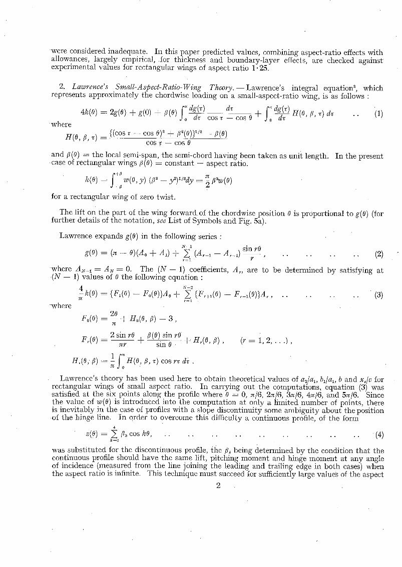
3. Description of the Exper iments . - -F ig . 1 shows the wing profiles employed. All the profiles were symmetr ica land had a thickness/chord ratio of 0.05. In each case the leading portion of the profile consisted of half an ellipse with a ratio of major to minor axes equal to 5 to 1. This was followed by a parallel portion and the trailing portion of the wing was formed by two circular arcs. a denotes the chordwise extent of the circular-arc trailing-edge portion and d the trailing- edge thickness. The specification of the profiles tested was as follows :
Profile A B C D E F
a/c 0.750 0.500 0.250 0.500 0.500 - -
d/t 0 0 0 0.333 0"667 1"000. The chord and span of all models were 32 in. and 40 in. respectively. Each model was built
up of a number of machined aluminium castings, held together internally by a number of short tongues. At the junction between the control surface and the main part of each model wing, angled tongues could be employed to hold the control surface at various fixed angles of deflection (see Fig. 2). In each case the gaps between the various sections of the model as well as between the control surface and the rest of the wing were sealed with thin cellulose tape. This was the arrangement employed for most of the measurements. The arrangement illustrated in Fig. 3 was used for the hinge-moment measurements and when a few measurements were made to explore the influence of the size of the gap, when unsealed, between the control surface and the main part of the wing.
The measurements were made in the 13 ft × 9 It Wind Tunnel at the National Physical Laboratory. The method of suspending the models from the tunnel roof balance is illustrated in Fig. 4. An image strut was used to evaluate strut interference effects.
3 (78373) " A*

Wires of 0.014-in. diameter were glued to both surfaces at 0.05c from the leading edge to fix the position of boundary-layer transition. Sufficient tests were made by the paraffin evaporation method to ensure that transitiofl was taking place at the wire on both surfaces over the range of values of incidence and control-surface deflection employed during the experiments.
The measurements were made at a Reynolds number, based on chord, of 2.6 × 10⁶.
Corrections were made to the results t o allow for wind-tunnel boundary constraint, support- strut interference effects, drag on the support struts and the rear suspension wire and drag on the transition wires.
The measured values of the most important coefficients are given in Tables 1, 2 and 3. Some typical sets of measurements are plotted in Figs. 6a to l i b and in Figs. 18a and 18b (for the notation see List of Symbols and Fig. 5b).
4. Discussion of the Results.--4.1. The Variation of Lift CoeJficient with Incidence.--Values of (al0)r, the theoretical lift-curve slope of a two-dimensional profile in incompressible potential flow, have been related to the thickness/chord ratio and the trailing-edge angle, st, by Bryant, Halliday and Batson (see Fig. 5 of Ref. (3)). Collingbourne ~ has given empirical curves from which al0, the lift slope of the two-dimensional profile allowing for boundary-layer effects, can be obtained. Collingbourne's relation at a Reynolds number of 6 × 10⁶ between A, which denotes (alo) r -- al0 and e, the angle between lines cutting the profile on each surface at 0.90c and 0.99c, and his relation between A and Reynolds number are reproduced in Figs. 12a and 12b. To deduce al, the lift-curve slope of the finite-aspect-ratio wing, Collingbourne suggests for unswept wings the relation
_ 1 [1 + A (1 4~ 1/~ al alO ~ J . . . . . . .
For profiles A, B and C at the Reynolds number of test (2.6 × 10⁶) and for an aspect ratio of 1-25, the estimated and measured values of al are compared in the accompanying Table. It will be seen that this method of estimating al works well in the present cases. The value of al, derived by Lawrence's theory, making no allowance for thickness or boundary-layer effects is 1.75.
Profile t/c
A 0.05 B 0.05 C 0.05
(deg)
7.6 11.5 22.8
(deg)
7.0 10.2 17.9
(410) ~.
6"53 6-54 6"55
A(6 × 10⁶)
0"43 0"52 0"90
A(6 × 10⁶) A(2.6 × 10⁶)
0"79 0"79 0-79
0"54 0.66 1.14
Re = 2-6 × l0 G
Estimated 410
t71
5.99 1.78 5.88 1.77 5.41 1.72
Measured a I
1 "85 1 "80 1"75
Comparing in Table 1 the values of al for profiles D, E and F with those for profiles A, B and C, it can be seen how surprisingly little influence trailing-edge thickness has on the lift-curve slope.
4.2. The Variation of Lift Coefficient with Flap Angle.--Bryant, Halliday and Batson 3 have discussed in a comprehensive manner the factors governing the value of as for two- dimensional aerofoils and they have given some curves, derived empirically, from which a2o/(a2o)r can be estimated. Here as0 denotes the value of as for a two-dimensional profile and (a,0)r t h e theoretical value when no allowance is made for boundary-layer effects. Specifically in Fig. 17 of Ref. (3) a~o/(a,o)r is plotted against E for various constant values of alo/(alo)r and the authors suggest that these curves are independent of transition position and probably of Reynolds number : the values of a,o/(a~o)r appropriate to profiles A, B and C have been obtained from this Figure by interpolation or extrapola.tion and are given in the attached Table. The values of

(a~0) r were determined, using the values of (at0)r given in Section 4.1, on the assumption that (a~o/alo) r is independent of thickness and has the same value for profiles A, B and C as for thin flat plates. Hence the values of a~0 and, using the estimated values of al0 given in Section 4.1, of a~o/alo could be obtained.
According to lifting-line theory a~/al should be independent of aspect ratio. However, calcula- tions based on Lawrence's theory show a progressive change in adal as the aspect ratio is decreased. The results of such calculations for rectangular wings of various aspect ratios and with various values of E are presented in Table 4 and in Fig. 13. In the attached Table, estimated values of adal for profiles A, B and C at aspect ratio 1.25 have been obtained simply by scaling up the values of a~o/alo in proportion to the change of adal for a thin flat plate in inviscid flow when the aspect ratio is decreased from infinity to 1.25, i.e.,
estimated value of a~ _ a~0 X 41 410
X Value of 4 2 / 4 1 for a thin flat plate of aspect ratio 1-25 ill inviseid flow
/ Value of 42 4 1 for a thin flat plate of infinite aspect ratio in inviscid flov~
Strictly speaking, of course, separate 'correct ions ' for (low) aspect ratio and boundary-layer effects cannot be made and this is a crude procedure but there seems reasonable hope of success if it is applied to those quantities which according to lifting-line theory, are independent of aspect ratio. The procedure is to be justified by comparing the estimates, which it provides, with experimental results.
Profile
A
B
C
E
0.250
0"125 0.250 0.375 0.500
0.250
.lo/(alo)~
0.917
0.899 0.899 0.899 0.899
0.826
0.933
0-807 0.901 0.933 0.944
0.771
0-619
0.394 0.611 0-756 0-859
0.568
Values of (a2/al),
A = o o A
0.609
0.441 0.609 0-728 0-818
0.609
= 1.25
0.724
0.556 0.724 0-825 0-890
0.724
Ratio
1.19
1 "26 1"19 1" 13 1.09
1-19
R~ = 2.6 × 10⁶
Est imated a2/al
0-787
0.496 0.727 0.854 0.936
0.676
Measured a2/al
0-643
0.467 0.672 0.783 0.889
0-652
In fact, it will be seen from the Table that the agreement between estimated and measured values of a2/al is fairly good. In five of the six cases the estimated value is within 10 per cent of the measured value and in the remaining case (profile A) the discrepancy is less than 15 per cent. In every case the measured value of a2/al lies between the estimated value of adal and the estimated value of a2o/ao. Estimated and measured values of adal for profile B are also compared in Fig. 14.
The measured values of a~/al for profiles D, E and F, listed in Table 1, are all somewhat greater than those for profiles A, ]3 and C and in every case except one approach more closely the values predicted by Lawrence's theory. Indeed, in every case except one (profile F with E -- 0. 250) the measured values of adal for profiles D, E and F are within 5 per cent of the corresponding value of (adal)~ given by Lawrence's theory.
4.3. Position of Centre of Pressure.--Table 5 and Fig. 15 show how, according to Lawrence's theory, the position of the centre of pressure of the aerodynamic load due to flap deflection should vary with the ratio of flap chord to overall chord for rectangular wings of various aspect ratios. In each case, of course, the c.p. position, when E has the value unity, is the c.p. position of the aerodynamic load due to incidence. The accompanying Table shows how the measured values compare with the theoretical values for the particular cases of aspect ratio 1.25. I t will
5

be seen tha t for profiles A and B the greatest discrepancy between the theoretical and measured c.p. position is less than 1½ per cent of the overall chord while for profile C there are discrepancies of between 2 and 3 per cent of chord• Surprisingly the observed c.p. positions for profiles D,
Values of xc/c : Wings of Rectangular Plan-form and A@ect Ratio 1.25
E 0. 125 0.250 0.375 0- 500 1. 000
Theoretical value .. 0. 677 0. 597 0.516 0.434 0. 183
Profile A Profile t3 Profile C Profile D Profile E Profile F
0.663
0.676
0.605 0.590 0.570 0.598 0.589 0.584
O. 520
O. 523
0-427
0-436
0.183 0.176 0.164 0.186 0•207 0.206
E and F with large trailing-edge thickness are also in good agreement with theoretical expectation, the greatest discrepancy being less than 3 per cent of the chord• The measured results for profile E and the theoretical results for aspect ratio 1.25 are plotted in Fig. 16. I t is clear tha t Lawrence's theory can be used confidently to predict c.~p. position, at least for wings of rectangular plan-form.
4.4. Drag.--The values of the drag coefficient of each profile at zero incidence and with zero flap deflection are given in Table 1. The corresponding value of CD 0 for a smooth flat plate at the same Reynolds number (2.6 × 10⁶) and with the same transition position (0.05c downstream of the leading edge) is 0.0073. Natural ly the profiles with finite trailing-edge thickness have a much larger drag than the profiles with zero trailing-edge thickness. Figs. 17a to 17f show that for all six profiles the induced drag associated with incidence or flap deflection is well represented, even for wings of such low aspect ratio, for all values of E by the expression CL~/~A, derived for an elliptically loaded lifting line. Some of the scatter is attributable to variations in profile drag with flap deflection.
4.5. Gap Effects.--All the results quoted previously were obtained with the gap between the control surface and the main part of the wing sealed. The effect of the size of the gap, when the gap is not sealed, was examined on profile F with a 25 per cent chord control surface only. The arrangement of the model of this purpose is illustrated in Fig. 3. The effects on al, as and c.p. position are summarised in the accompanying Table :
Change in Value of Coefficients with Unsealed Gap
Gap size (in•)
O" 125 O" 250
Gap OveraIi chord
(per cent)
O- 390 O" 781
--0.04 - -0 .06
Cg 2
0 0
Profile F, 'E = O' 250
x,/c
--0. 005 --0.004
xo/c
+0-014 +0"018
Unfortunately, before these measurements were made an accident in the tunnel resulted in bending of the support struts and, as no fresh determination of the support interference effect was made, the results have to be treated with caution• In fact, the values of al, as and c.p. position were not quite the same with the present arrangement and a very small gap (0.010 in.) as those obtained with the sealed-gap model arrangement (Fig. 2), used in the earlier measure- men t s : it seemed reasonable to attribute the small discrepancies to changes in the support interference effect and to the small change in control-surface area. The differences quoted in the Table were obtained by comparison with the model arrangement of Fig. 3 with a gap of 0.010 in. (0.031 per cent of overall chord) and it has been assumed that such a small gapis effectively a sealed gap.

I t appears t ha t the effects of the two gap sizes a re small. 31 is reduced by 2 or 3 per cent, a= is unal tered, the c.p. position of the ae rodynamic load due to incidence is moved forward about 0- 5 per cent of the overall chord and the c.p. position of the ae rodynamic load due to flap deflection is m o v e d back about 1-5 per cent of the overall chord.
i t is more difficult to p r e s e n t a concise s t a t ement on t h e effect of gap size on drag. This is pa r t ly because the scat ter of some of the results was ra ther too large to permi t detai led analysis of r a the r small effects. Some correlat ion is na tu ra l ly to be expected wi th CL since this influences the flow throug h the gap. Wi th ~ = 0 and ~ ---- 0 (CL = 0), CD was increased by about 0" 0003 at gap sizes of 0. 125 in. and 0. 250 in. as compared With 0. 010 in. W i t h ~ = 6 deg and ~ a-=6 deg (CL = 0.36), C~ was decreased by 0. 0011 at a gap size of 0. 125 in. and by 0. 0023 at a gap size of 0. 250 in. W i t h c¢ = 6 deg and ~ = -- 3 deg (C~ = 0.14), CD was the same at the three gap sizes of 0. 010, 0- 125 and 0. 250 in.
For this case (profile F with E = 0. 250) at least, it seems clear t ha t the size of the gap be tween the control surface and the main par t of the wing exercises no ve ry great influence on 31, a~, C~ or c.p. position, if the gap wid th is a round 0-5 per cent or less of the overall chord.
4.6. Hinge Moments.-- Hinge moments were measured only in two cases, namely , on profiles ]3 and F, each fi t ted wi th a 25 per cent flap. The measured values in the case of profile B are p lo t ted in Figs. 183 and 18b • the corresponding curves for profile F exhibit qual i ta t ive ly the same features of non-l ineari ty. The values of bi and b2 for bo th profiles are given in Table 3. I t will be observed t ha t the values are considerably larger for profile F than for profile B:.
Es t imates of h inge-moment coefficients for a wing wi th profile B and of infinite aspec t rat io have been made by the me thod proposed by Bryant , Ha l l iday and Ba t son t The Values of the re levant quant i t ies used in the es t imat ion of blo/ao were as follows •
E = 0.250, tic = 0.05, er = 11"5 deg, al0/@tl0)T ~ - - - 0.899, (bto/alo)r = -- 0 - 0 8 0 6 , '
b~o/alo = 0.86, (b~o/a~o) r = -- 0-0693.
Since the re levant da ta in Ref. (3) relate only to values o r e equal to 0 .20 and 0.40, the value corresponding to an E of 0. 250 was obta ined by linear in terpolat ion ; this seemed not too serious a risk since the two values given differed by only about 10 per cent. The values of fur ther re levant quant i t ies used in the es t imat ion of b0 were as follows •
(b~o/b~o)r = 0 , 5 9 9 , (b~o/a,o) = (b2o/a~o)r in this par t icular instance,
:: b ~ o = - - 0 " 7 9 1 , b 0 = - - 0 " 5 4 2 . A similar difficulty arose in the es t imat ion of b~o/a~o to t ha t which arose in the es t imat ion of blo/a~ol
According to lifting-line theory b~/a~ and b are independent of aspec t ratio. Calculations based On Lawrence ' s theory, however, show a gradual change of bo th these quant i t ies as the aspect rat io is decreased. The results of such calculations for rec tangular wings of various aspect ratios and wi th various Values of E are presented in Tables 6 and 7 and in Figs. 19 and 20. Es t ima ted values of bl/a~ and of b were obta ined by scaling up the values 0f b~o/ao and of b0 in t h e following w a y •
es t imated value of b~ (or b) = b~-2° (or bo) × : = a l a 1 0 - -
X v a h m of bl/6~1 (or b) fora thin flat plate of ,~l~Jte aspeot ratio in inviscid flow" . . -
A S already noted in Section 4.2, this is a somewhat-crude procedure, i i
The es t imated and measured values for profile B are as follows • : . . . .
_ b l / a l b _ .
~ . . . E s t ima ted - -0 .036 - -0 .427 , .
Measured - -0 . 026 - -0 .396 . . . . . . . ;
7
(78373) A**

The percentage discrepancy between the estimated and measured values of bl/a~ is rather large but both estimated and measured values are dubious : the main point is that bl is a relatively small and unimportant quanti ty. The percentage discrepancy between the estimated and measured values of b is about 8 per cent. Since bl is small, this implies tha t the estimate of b~ is reasonably good. In fact the estimated and measured values of b2 are respectively --0-473 and --0.427, a discrepancy of just over 10 per cent: In view of the non-linearity shown in Fig. 18b, accuracy of estimation of this order seems adequate.
4.7. Effect of Finite Trailing-Edge Thiekness.--Earlier measurements ~ on a torpedo model suggested that, if streamlined fins of aspect ratio about 1 were replaced by fins fitted with parallel-sided control surfaces of thickness equal to the maximum thickness of the fin, then a, should be increased by between 50 and 60 per cent for values of E lying between 0.10 and 0.25. This expectation has not been fulfilled in the present measurements on fins in the absence of a model torpedo hull. As already discussed, it can be seen from Tables 1 and 2 that the values o f a~ for profiles ]3 and F are about the same while the value of as for profile F is larger than that for profile ]3 only by amounts varying from 5 to 13 per cent for values of E between 0. 125 and 0.500. The measurements on the torpedo model were made at a Reynolds number (based on fin chord) rather less than one-fifth of that of the present measurements. I t may be tha t profiles ]3 and F would have shown the expected difference at the lower Reynolds number. Alternatively the much larger value of a2 obtained in the earlier tests with the parallel-sided as compared with the streamlined control surfaces may have been due to a difference in the interaction between control surface and hull. Not only was the expected increase in a~ not realised in the present measurements but it was also found that the hinge moment on the control with the thick trailing edge was greatly increased.
S. Summary and Conclusions.--The results of a programme of wind-tunnel measurements of the lift, drag and pitching moment on a number of model wings, each fitted with a full-span plain flap, and of a much more limited programme of hinge-moment measurements have been presented. The wings differed from one another in profile but all were of rectangular plan-form and of aspect ratio 1.25. The flap chord was varied between 0. 125 and 0. 500 of the overall chord. Three of the profiles investigated were conventional in having zero trailing-edge thickness but the other three had large trailing-edge thickness, a feature thought to be of interest in connection with the design of torpedo fins.
Contrary to expectation the present measurements do not suggest any substantial advantage from fins w i t h finite trailing-edge thickness as compared with the ' conventional ' profiles. Finite trailing-edge thickness gives rise to larger hinge moments and, of course, to greatly increased drag.
Theoretical values of a~/al, bl/al, b and of the positions of the centres oL pressure of the aero- dynamic load due to incidence and flap deflection for thin flat rectangular wings of various aspect ratios in inviscid flow have been calculated and the results are presented in graphical and tabular form. The influence of thickness and boundaryqayer effects on the two-dimensional characteristics of the profiles employed has been assessed from the best available (mainly empirical) data. The measure of agreement between the predicted values, obtained by combining thickness, boundary-layer and aspect-ratio effects and the measured values of al, a~/al, bl/a~, b and of c.p. positions for the conventional profiles is fairly satisfactory. Although the aspect ratio was small, the induced drag associated with incidence and flap deflection was found to be well represented by the usual expression derived from consideration of the elliptically loaded lifting line. A limited number of measurements suggested that the size of the gap between the control surface and the main part of the wing exercises little influence on a~, as, CD or C.p. position if the gap width is less than 0.5 per cent of the overall chord.
Acknowledgment.--The computations of theoretical values from Lawrence's theory were carried out under the supervision of Mr. G. Owen by the Mathematics Group, Admiralty Research Laboratory.

a
alO
g l
ago
a~
(a~),
A
A,
blo
b~
b~0
b~
b0
b~
C
Ca
CDO CA
CL
d
LIST OF SYMBOLS
• A geometrical parameter used in specifying profiles (see first paragraph of Section 3)
~Cz/a~ for a two-dimensional profile
Theoretical value of al0, including thickness but not boundary-layer effects
= ~CL/a~ for a wing of finite aspect ratio
Theoretical value of al, no allowance being made for thickness or boundary- layer effects
---- 8CL/8~ for a two-dimensional profile
Theoretical value of a2o, including thickness but not boundary-layer effects
= ~CL/~ for a wing of finite aspect ratio
Theoretical value of as, no allowance being made for thickness or boundary- layer effects
Aspect ratio
Coefficients defined by equation (3)
= aCn/8o: for a two-dimensional profile
Theoretical value of blo, including thickness but not boundary-layer effects
---- 8Cn/8~ for a wing of finite aspect ratio
Theoretical value of b~, no allowance being made for thickness or boundary- layer effects.
------ 8C./8~ for a two-dimensional profile
Theoretical value of b20, including thickness but not boundary-layer effects
---- 8CH/8~ for a wing of finite aspect ratio
Theoretical value of b~, no allowance being made for thickness or boundary- layer effects
b~o a2__o bl0 ~0
b2 - - ~ bl fA x
(o.) " Wing chord
Drag coefficient
Value of C~ when ~ and ~ are both zero
Hinge-moment coefficient (based on control-surface area and control-surface chord)
Lift coefficient
P i tc l~g-moment coefficient (referred to leading edge)
Trailing-edge thickness
9 (78373) A**2

E
F,(O) g(o)
H(o, ~, ~) H/o, ~)
k(o) t
. U
- ~(o,y)
Xi
Xc
y , Z
o~
~(o)
A
• ' , 8 , S T
0
P
LIST OF SYMBOLS--cont inued
Ratio of flap chord to overall chord
Functions defined following equation (3) (Lift on part of wing forward of the chordwise position O)/2pU 2
Functions defined following equation (1)
Functions defined following equation (3)
Function defined following equation (1)
Maximum thickness of aerofoil
Free-stream velocity Local inclination of aerofoil mean camber line to free-stream direction
Centre-of-pressure position for aerodynamic load due to incidence (see Fig. 5b)
Centre-of-pressure position for aerodynamic load due to flap deflection (see Fig. 5b)
Co-ordinates defined in Fig. 5a
Angle of incidence
Local semi-span of wing
Semi-span of rectangular wing
Coefficients defined in equation (4)
( ~ 0 ) ~ - ~0
Trailing-edge angles (see Section 4)
Flap deflection angle
Angle specifying chordwise position (see Fig. 5a)
Fluid density
No. Author
• , 1 " C .F . Blanks and D. A. Leaver
2 H . R . Lawrence . . . . . .
L. W. Bryant , A. S. Hal l iday and A. S. Batson.
4 J . R . Collingbourne . . . .
REFERENCES Title, etc.
A.R.L. Report (Unpublished). ,
The lift dis t r ibut ion on low-aspect-ratio wings at subsonic speeds. J. Ae. Sci. pp. 683 to 695. October, 1951. ,,
Two-dimensional control characteristics. 1~. & M. 2730. April, 1950.
A.R.C. Paper (Unpubl i shed) .
10

TABLE 1
= o )
Profile a/c d/t a s x,/c C J) o
A B C
D E F
0-750 0-500 0"250
0"500 0'500
0 0 0
0"333 0"667 1:000
1"85 1,80 1"75
1 "83 1.85 1 .86
0-183 0.176 0.164
0.186 0.207 0.206
0.0077 0-0082 0-0083
0-0119 0.0205 0.0279
T A B L E 2
=o)
Profile a/c E Ct 2 ~2/al xc/c
A
B B B B
C
D
E
F F F F
. 0.750
0-500 0-500 0.500 0.500
0.250
0.500
0.500
0 0 0 0
0.333
0.667
1.000 1.000 1.000 1.000
0"250
0.125 0"250 0"375 0'500
0.250
0.250
0"250
0-125 0-250 0-375 0.500
1"19
0.84 1-21 1"41 1-60
1" 14
1"27
1"32
0.95 1.32 1.50 1.69
0.643
0.467 0.672 0-783 0-889
0. 652
0.694
0.714
0.510 0.710 0.806 0.908
0.605
0.663 0.590 0.520 0.427
0-570
0- 598
0.589
0.676 0-584 0.523 0.436
-TABLE 3
Profile
a
B F
t~/C "
0.500
d/t
0 1. 000
E
0.250 0.250
bl
--0.046 --0.136
bl/al
--0.026 --0.073
b2
--0-427-. --0.617
-b
0.396- --0.520
11

TABLE 4
Values ~(a2/al),#rFlat Wi~s ~ Rectangular Plan-form accordi~ to Lawrence's Theo~
E 0.050 0.125 0.250 0 . 3 7 5 0.500 0-750 1.000
A = 0 1 2 4 O(3
1.000 0.401 0.343 0.311 0.282
1.000 0.584 0.511 0.473 0.441
1.000 0.751 0.679 0.642
0 . 6 0 9
1.000 0.847 0.788 0.756 0.728
1.000 0.904 0.863 0.839 0.818
1.000 0.965 0.955 0.948 0.942
1.000 1.000 1.000 1.000 1.000
TABLE 5
Values of xc/c for Flat Wings of Rectangular Plan-form according to Lawrence's Theory
E 0.050 0.125 0.250 0.375 0.500 0.750 1.000
A = O 1 2 4
0"950 0"766 0"660 0"585 0"483
0-875 0"706 0-618 0"550 0"459
0-750 0-622 0"549 0-493 0"420
0-625 0-535 0-479 0-437 0-382
0"500 0"445 0"411 0"383 0"347
0.250 0.274 0" 286 0" 289 0-287
0 0. 167 0.209 0.231 0.250
T A B L E 6
Values ~(bl /a l ) ,#rFlat W i ~ s ~ Recta~ularPlan-form accordi~ to Lawrence's Theo~
E 0-05 0.125 0.250 0"375 0-500 0-750 1'000
A = O 1 2 4 oo
0 --0"0161 --0.0265 --0.0338 --0.0379
0 --0.0260 --0.0429 --0.0539 --0.0618
0 --0.0387 --0-0632 --0.0781 --0.0900
0 --0"0504 --0.0811 --0.0989 - - 0 . 1 1 4 0
0 --0-0633 --0.0989 --0.1192 --0.1366
0 --0"0973 --0.1399 --0.1634 --0-1838
0 --0.1674 --0.2089 --0.2309 --0.2500
TABLE 7
Values ~ ( b ) , # r Flat Wigs ~ Recta~ular Plan-form accordi~ to Lawrence's Theo~
E 0.05 0.125 0-250 0.375 0.500 0.750 1-000
A----0 1
2 4 co
0 --0.714 --0.755 --0.777 --0.798
0 --0.600 --0.659 --0"692 --0.723
0 --0.442 --0.517 --0"557 --0"599
0 --0.320 --0.396 - -0 '436 --0-479
0 --0.223 - - 0 . 2 8 9 - - 0 . 3 2 4 --0"363
0 --0. 082 - -0 - 114 --0" 132 --0" 150
!2

C
D
J~
F
FIG. 1. Profiles.
13

I
F L O W .
I . SLOT IN ITEM "A"PERMITS FREE MOVEMENT BETWEEN O°'-IO°o 2, BLOT IN ITEM "S" IS CUT AT A FIXED ANGLE (O° :3 ° :6 ° & 907
49 ° SLOT ILLUSTP~ATED} SLOT IB A GOOD FIT ON TONGUE OF ITEM'C' . R, EPLACING ITEM "A" WITH ITEM "B" GIVES FIXED ANGLE,
3 , SLOTTED HOLES IN ITEM 'C" PE~kJ, IT VARIATION OF HINGE GAP / FROM "O1" TO ' / 4 " . ..~ f
\
FIG. 3. Scrap view of freely hinged joint.
~'B \
FIG. 2. Fixed-hinge model.--9-deg angle illustrated.

u
- 1
. . . . . . . . : 7 . . . . . . . . . . . : . . . .
. , . . .
E
I
~--%
- - p
i
O 5 0 " D(A BRUNTON
' ; NOSE PROFILES
_ _ ~ - ~ - - - = 6" - - ~ i C ~ , i
. . . . . I . . . . .
32// ,
l -
' / " / ;~x \ M I . A ' r ~ o N . -. ~ / \\
d~
4 0 / I
W(ND TUNNEL AX IS
c / z
P L A N
T
±
FIG. 4. General arrangement of wind-tunnel model.
ELEVATIO~
L
";CL DEFINES CENTRE OF PRESSURE OF AERODYNAMIC LOAD DUE TO INCIDENCE
FIo. 5a. Notation.
"3~c DEFINES CENTRE OF PRESSURE OF AERODYNAMIC LOAD DUE TO FLAP DEFLECTION.
FIG. 5b, Notation,
15

PROFILE B *q :0 o.2- - -
0 " 1 -
CL
2 Z~
FIG. 6a.
0.0~.-
-6 -~, -2
- O,0Z
- 0"04
c= PROFILE B ~ = 0
FIG. 7a.
O'b
FIG. 6b. FIG. 7b.

° 9
O.OX
0-01.
1 l = 0
I - 6 - ~ - z
Co
z z~
PROFILE B
FIG. 8a.
-G - 3 3 ¢,,
] I
m -
(,,
PROFILE F %-'0
O,Z-
O.I
FIG. 9a.
I -O-I
CI.
---2--
"-3
FIG. 8b. FIG. 9b.

oo
. o'0.4.-
• -0.02
- 0 . 0 4
c,. PROFILE F
d,(°)
~ 2 a - ' c~
FIG. lOa.
FIG. lOb.
-6
' c o
0 - 0 4
-'} = o
0 , 0 2
-4 -2
PROFILE F
FIG. l l a .
"9 -6 -3
Fig . 1 lb .
3 6 9
~C o)

I,S
1.0
0,5
~PER RADIAN) Re = 6 X [O G
(AFTER COLLINGBOURNE)
( D E G R E E S )
5 .... " I0 15. 20- 25.
FIG. 12a.
I.O
0.5
(6x,o ~)
' % " " " " I I
(AFTER COLLINGBOURNE)
LO% Re
D
6.0 6,2 6.4 6,6 6,8 7.0
FIG. 12b.
2
_ L
19

Q
I ' 0 0
O. 80--
0 .60
0"40
0 " 2 0
A
FOR FLAT WINGS OF RECTANGULAR PLAN
E
C~-20 0"40 0.60 O.BO 1,00
FZG. 13.
1.00
0.80
0 , 6 0
0 . 4 0
0,20
%=, PROFILE B (A "~1.25, Re;2.6 X IO G )
ESTIMATED
MEASURED
o.2o 0.40 0.60 o.so
FIG. 14.
E
1,00

I ' 0 0
O ' 8 0
0"60, -
0 ' 4 0
0 ' 2 0
FOR FLAT WINGS OF RECTANGULAR PLANFORM
_A I
0-20 0-40 0 ,60 O.80
OO
Z
I
E -- 0 ----~ .00
FIG. 15.
1.00.
0,'80
0 , 6 0
0"4 0
0.20
x%
K '
r THeOrY
| RECTANGULAR PLANI~ORM MEASUREMENT ~' CPROFILIEB ) j A ~ 1,25
0.20 0~0 0.40 .... 0,60
FIG. 16.
£ r
1.00

! -
3
0 . 0 !
0 . 0 4 .
0 , 0 3 _
0 . 0 2
0 .01
C D " ~ :
P
l
i i
PROFILE A
(~: oooo O, 1~ 2 , 4 , 6
o i
E = ~ - 2 5 O I ~ .;i.,3,:,,;6a, q.§° - • -... . . . . . . k ~
7 j . . i i
' i
~r
; 0 . 0 5
i
t i
O.IO
FIG. 17~
i
l .
i J \
C D = Coo "')"
3 .
O,15
~ A
2
,:: , ~,
2 C L .
0 . 2 0
22

b.% O0
0.06
0.05
0 , 0 4
0.03
0 . 0 2
0 - 0 1
CD PROFILE B • [ ~ . = O~ I °, 2 0 4 0 6 °
('q=o
÷ E = 0,125 ]
o E 0 .375 I "-*-3'°+'6°+9'° E O.5OOJ
o
"Po ° x ~
• x
+~
o
~ C o = Coo+ cz ";cA:
0.05 O,IO
FIG. 17b.
0,15 0 . 2 0 0.25

Co P R O F I L E C
0 , 0 !
0 .04
O, 03
0.02
0 . 0 1
' t'q o ~ ='= °' '°' 2°' 4'0 6 ° o . , / ' / /
x H - o 6. / "
E 0 250 ~L'~ = '1'3°~+-6° ~g ° / C
hOS 0-10 0.1':; ~,20
FIG. 17c.
c
0 . 0 5
0.05
0 , 0 4
0.03
0.02
o .Ol
CD PROFILE D ,j~ o, ,~ ~o,4o, 0o ' ' I /
[y ° . ~
E= °'2s° 1~q-- -~3~ t6%~9 °
c~ o . o s o . l o o . , s
FIG. 17d.
0. ;10
24

0.061
0-05
0,04
0.03
O. 02
0,01
c~ PROFILE E
. • ~"~ : O, I° :3° 4'~ 6° J
° ,t j ~ "
c~ ~ A
0,05 0,I0 0.15
FIG. 17e.
0.20
2 CL
25

b~
CD
~o. PROFILE F
{~ = 0 P, 2 ° 4 ° 0 °
" 0
0 , 0 8 + E = 0 . 1 2 5 ]
x
0 E : 0 . 3 7 5 / ~3R,: 5°7- go
,~ E : 0 . 5 0 0 )
0 - 0 7
I 0.015
0.05
0 , 0 4
z~
0.03
I ~ 0
0 .02
0.01
2 C o = C~o Jr C t- - -
?TA
/
0.05 040 0"15 0.20
C 2 k
0-25
FIG. 17f.

O'OZ-
0 ,0 ! -
-0.01
- 0"02
PROFILE B "1l=0
FIG. 18a.
PROFILE B E = O. ZSO
I -~ -(o
r/(°)
-0-I
\
-0.~
-0.0~
-0.f0
F m . 18b.
2 7

o
~b
L~O 00
0 " 2 0 0-40
FOR FLAT WINGS OF PECTANGULAi? PLANFORM
0 " 2 0
O' 15
A
0,6O 0 80 I'00
E
FIG. 19.
O O.20 0 .40 O.60
1 .00
0.80
0.60_
0,40
O,20
-4
FOR FLAT WINGS OF RECTANGULAR PLANFORM
0.~,0 I,O0
FIG. 20.
E m

R. & M. N o . 3 1 4 2
Publications of the Aeronautical Research Council
A N N U A L T E C H N I C A L REPOP~TS OF' T H E A E R O N A U T I C A L ~ E S E A ~ C H C O U N C I L ( B O U N D V O L U M E S )
1939 Vol. I. Aerodynamics General, Performance, Airscrews, Engines. 5os. (52s.). Vol. II. Stability and Control, Flutter and Vibration, Instruments, Structures, Seaplanes, etc.
63s. (65s.) 194o Aero and Hydrodynamics, Aerofoils, Airserews, Engines, Flutter, Icing, Stability and Control,
Structures, and a miscellaneous section. 5os. (52s.) 194I Aero and Hydrodynamics, Aerofoils, Airscrews, Engines, Hurter, Stability and Control,
Structures. 63s. (65s.)
1942 Vol. I. Aero and Hydrodynamics, Aerofoils, Airserews, Engines. 75s. (77s.) Vol. II. Noise, Parachutes, Stability and Control, Structures, Vibration, Wind Tunnels.
47s. 6d. (49 s. 6d.) I943 Vol. I. Aerodynamics, Aerofoils, Airscrews. 8os. (82s.)
Vol. II. Engines, Hurter, Materials, Parachutes, Performance, Stability and Control, Structures. 9os. (92s. 9d.)
1944 Vol. I. Aero and Hydrodynamics, Aerofoils, Aircraft, Airscrews, Controls. 84s. (86s. 6d.) Vol. II. Flutter and Vibration, Materials, Miscellaneous, Navigation, Parachutes, Performance,
Plates and Panels, Stability, Structures, Test Equipment, Wind Tunnels. 84s. (86s. 6d.)
1945 Vol. I. Aero and Hydrodynamics, Aerofoils. 13os. (I32S. 9d.) Vol. II. Aircraft, Airserews, Controls. 13os. (132s. 9d.) Vol. III. Flutter and Vibration, Instruments, Miscellaneous, Parachutes, Plates and Panels,
Propulsion. I3OS. (132s. 6d.) Vol. IV. Stability, Structures, Wind Tunnels, Wind Tunnel Technique. 13os. (132s. 6d.)
A n n u a l N e p o r t s o f t h e A e r o n a u t i c a l l ~ e s e a r e h C o u n c i l - 1937 2s. (2s. 2d.) 1938 IS. 6d. (IS. 8d.) I939-48 3s. (3s. 5d.)
I n d e x t o a l l R e p o r t s a n d M e m o r a n d a p u b l i s h e d i n t h e Annual T e c h n i c a l R e p o r t s , and separately--
April, 195o R. & M. 2600 23. 6d. (2s. Iod.)
A u t h o ~ I [ n d e x t o a l l Reports and Memoranda of the A e r o n a u t i c a l ~esearch Council--
1909--January, I954
Indexes to the Technical Reports Council--
December I, I936--June 3 o, 1939 R. & July I, I939--June 3 o, I945 R. & July I, I945--June 3% 1946 R. & July I , i946--December 3i, 1946 R. & January 1, 1947--June 3 o, 1947 R. &
]Published Reports and Memoranda C o u n c i l - -
Between Nos. 2251-234_ 9 R. & Between Nos. 2351-2449 R. & Between Nos. 2451-2549 R. & Between Nos. 2551-2649 R. &
R. & M. No. 2570 I5S. (I5S. 8d.)
of the Aeronautical Research
M. No. 185o lS. 3d. (is. 5d.) M. No. 195o IS. (is. 2d.) M. No. 2050 lS. (lS. 2d.) M. No. zISo IS. 3d. (is. 5,/.) M. No. 225o is. 3d. (is. 5d.)
of the Aeronautical Research
M. No. 2350 IS. 9 d. (IS. IId.) M. No. 2450 2s. (23. 2d.) M. No. 2550 2s. 6d. (2s. IOd.) M. No. 2650 2s. 6d. (23. IOd.)
Between Nos. 2651-2749 R. & M. No. 2750 2s. 6d. (2s. iod.) Prices in ~rackets include postage
HER MAJESTY'S STATIONERY OFFICE York House, Kingsway, London W.C.z; 4z3 Oxford Street, London W.I; 13a Castle Street, Edinburgh z; 39 King Street, Manchester 2 ; z Edmund Street, Birmingham 3 ; I°9 St. Mary Street, Cardiff~ Tower Lane, Bristol x ;
.. 80 Chichester Street, Belfast, or through any bookseller.
S.O. Code No. 23-3142
R. & M. N o . 3 1 4 2