Privileged accesss management for den csa user group CA Technologies
This chapter contains the following sections:
• Basic Management Security
• Access Lists
• Password Management
• Physical Security
• Out-of-Band Management Security
• Cisco Discovery Protocol (CDP)
• HTTP Configuration Services
• Simple Network Management Protocol (SNMP)
• Network Time Protocol (NTP)
• Banners
• Recommended Minimum IOS Security Settings
• TCP Intercept
• Summary
SS.book Page 34 Wednesday, May 2, 2001 2:11 PM
C H A P T E R 2
Basic Cisco Router SecurityThe first question any administrator should ask about a service is whether it is necessary to run that service in the present environment. If a service is not required, it should be disabled. Running a service that provides no functionality only burns up CPU cycles and exposes the network to potential attacks. If a service is required on the interior of the network, the administrator should make efforts to prevent that service from being seen from the exterior. Likewise, if a service is required on the exterior of the network, the administrator should attempt to limit the scope of the service to only the exterior portions.
Throughout this chapter, you will find several examples of services that pose potential risks of security breaches. Some of these services might be disabled by default, depending on the version of IOS being used. In these cases, the administrator is still urged to turn off the service specifically. The reason for this is to ensure that the administrator does not rely on his or her memory regarding which services are off by default on which versions of the IOS. Taking the time to turn off questionable services specifically will also make certain that the service is off even if the default changes.
As hackers, crackers, and script kiddies try new and inventive ways to break into your network, new threats will continue to emerge. One of the best ways to stay ahead of security threats is to keep current on the IOS version used on routers. Major security threats are consistently eliminated through new IOS versions. However, this does not relieve the administrator of the responsibility of using common sense and basic configurations that are sound. This chapter provides the basic configuration changes necessary to prevent your network from becoming susceptible to common attacks.
Throughout this chapter, you will be reminded that you should never intentionally divulge information regarding your network. The reason for this warning is that any information received by someone trying to breach security can and will be used against you. You should never intentionally divulge any information that does not need to be shared. Remember that the topic is security; in the realm of security, there is no such concept as being too careful.
This chapter is designed to teach the basic configurations necessary to begin securing your network. Advanced topics such as Terminal Access Controller Access Control System (TACACS), TACACS+, and Remote Access Dial-In User Service (RADIUS) authentication are explored in Chapter 10, “Securing the Corporate Network.” This chapter is limited in scope to the rudimentary commands.
SS.book Page 35 Wednesday, May 2, 2001 2:11 PM
36 Chapter 2: Basic Cisco Router Security
Basic Management SecurityBefore delving into specifics regarding how routers should be configured to help avoid attacks, the differences between internal and external devices must be explored. For purposes of this chapter, the authors use the word external as in external interface, meaning that the interface is directly connected to an untrusted entity. This can be the Internet, another company, or even a subsidiary of your own company. An internal interface is one that connects directly to a fully trusted network.
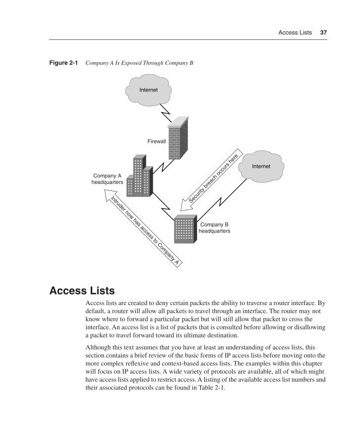
Many factors determine whether an entity is trusted. If there is doubt that the connected entity can be trusted, the authors recommend that the administrator not trust that entity. The initial reaction of many administrators will be to question why a wholly owned subsidiary should not be trusted. Consider the following example: Company A has a connection to the Internet. The administrator has done everything reasonable to ensure that the network is safe. Company B is a wholly owned subsidiary that has its own connection to the Internet. The administrators of these companies have sent a few e-mails to each other and talked on the phone a number of times to establish connection procedures and procedures for maintaining connections. However, Company A’s administrator has no authority, either explicit or implied, over Company B’s administrator. Upper management has decided that all subsidiaries will be entirely responsible for their own networks. If Company B’s administrator is not careful, Company A may become a target of attack through Company B’s network. Figure 2-1 illustrates this scenario.
This situation becomes more complicated when a company acquires several hundred subsidiaries. In a multinational company, one cannot possibly assume that each of the subsidiaries will always observe good security practices. Therefore, administrators should assume that any subsidiary of which they do not directly have control is easily breached. Likewise, the subsidiaries should assume that the main office is easily breached. Unless the administrator at the subsidiary personally knows all of the security steps taken within the main office, security should be implemented. Additionally, even if all offices provide adequate security, the only drawback to increased security will be a slight increase in latency and additional CPU requirements on the interface routers—both of which are very reasonable trade-offs for increased security.
In any case, a connection to another company that is not owned by your own company should be treated as a possible threat and considered an external interface. The reasoning behind this is the same as that for a subsidiary. Unless the administrator is able to constantly verify the security on any connection, it must be assumed to be a threat.
Now that the basic differences between internal and external connections have been explored, the chapter will move on to cover some specific settings on routers to discourage the most common forms of attack.
SS.book Page 36 Wednesday, May 2, 2001 2:11 PM
Access Lists 37
Figure 2-1 Company A Is Exposed Through Company B
Access ListsAccess lists are created to deny certain packets the ability to traverse a router interface. By default, a router will allow all packets to travel through an interface. The router may not know where to forward a particular packet but will still allow that packet to cross the interface. An access list is a list of packets that is consulted before allowing or disallowing a packet to travel forward toward its ultimate destination.
Although this text assumes that you have at least an understanding of access lists, this section contains a brief review of the basic forms of IP access lists before moving onto the more complex reflexive and context-based access lists. The examples within this chapter will focus on IP access lists. A wide variety of protocols are available, all of which might have access lists applied to restrict access. A listing of the available access list numbers and their associated protocols can be found in Table 2-1.
Internet
Internet
Firewall
Company Aheadquarters
Company Bheadquarters
Secur
ity b
reac
h oc
curs
her
e
Intruder now has access to Company A
SS.book Page 37 Wednesday, May 2, 2001 2:11 PM

38 Chapter 2: Basic Cisco Router Security
Any interface on a router may have up to two access lists assigned: one will control inbound traffic, and the other will control outbound traffic. All access lists, regardless of protocol or interface, operate based on six principles:
• Access lists usually deny that which is not specifically permitted, because traffic is generally allowed by default.
• Access lists control traffic in one direction (inbound or outbound) on an interface.
• Every packet traversing the interface is examined against an applied access list in the direction of that packet.
• Packets are compared to the access list starting at the top of the access list and continuing until a match is found. The implied deny statement at the end of an access list is considered a match.
• Outbound packets are routed to the appropriate interface before the access list is applied.
• Inbound packets are compared to the access list and, if permitted, are routed to the appropriate interface.
• Any interface may have a maximum of one access list applied to the inbound traffic and a maximum of one access list applied to the outbound traffic.
Table 2-1 Access List Numbers and Associated Protocols
List Range Protocol Notes
1–99 IP Standard IP access list
1–100 Vines Standard Vines access list
100–199 IP Extended IP access list
101–200 Vines Extended Vines access list
200–299 Type Code Ethernet Type Code, transparent bridging Type Code, or source–route bridging Type Code access list
201–300 Vines Simple Vines access list
300–399 DECnet DECnet and Extended DECnet access list
400–499 XNS XNS access list
500–599 XNS Extended XNS access list
600–699 AppleTalk AppleTalk access list
700–799 Vendor Code Source-route bridging Vendor Code access list
800–899 IPX Standard IPX access list
900–999 IPX Extended IPX access list
1000–1099 IPX IPX Service Access Protocol1 access list
1SAP=Service Access Protocol
SS.book Page 38 Wednesday, May 2, 2001 2:11 PM

Access Lists 39
Access lists are made in one of several forms; the most common are standard and extended. Because standard access lists are simpler by nature, they will be examined first.
Standard Access ListsStandard access lists deny or permit packets traversing a router interface based solely on the source address of the packet. Numbered 1 through 99 for IP, standard access lists must be defined before they can be used. Figure 2-2 shows that a router, by default, allows all traffic through to the intended destination.
Figure 2-2 By Default, a Router Allows All Traffic Through
Applying an access list, however, will change this behavior. When an access list is applied, a router acts as a firewall. The function of a firewall is to restrict traffic traveling through itself. As shown in Figure 2-3, adding an access list changes the behavior of the router. When an access list is applied, only traffic that has specifically been allowed will be able to travel through the router. In the example shown in Figure 2-3, traffic from the 10.2.2.0/24 network is allowed to traverse the router. Because no other traffic has been allowed, traffic originating from the host 10.1.1.1 will not be allowed through.
The syntax for creating a standard IP access list is as follows:
access-list access-list-number {deny | permit} source [source-wildcard]
With this syntax, access-list-number is any number from 1 through 99 that defines the access list number. The parameter permit or deny specifies whether to allow or disallow the packets. The parameter source is the IP address of the host sending the packets to be denied, and source-wildcard is the wildcard mask for the host or hosts sending the packets.
All access is allowed
All access is allowed
Router without anyaccesss list configured
Connection from 10.1.1.1
Connection from 10.2.2.2Internet
SS.book Page 39 Wednesday, May 2, 2001 2:11 PM

40 Chapter 2: Basic Cisco Router Security
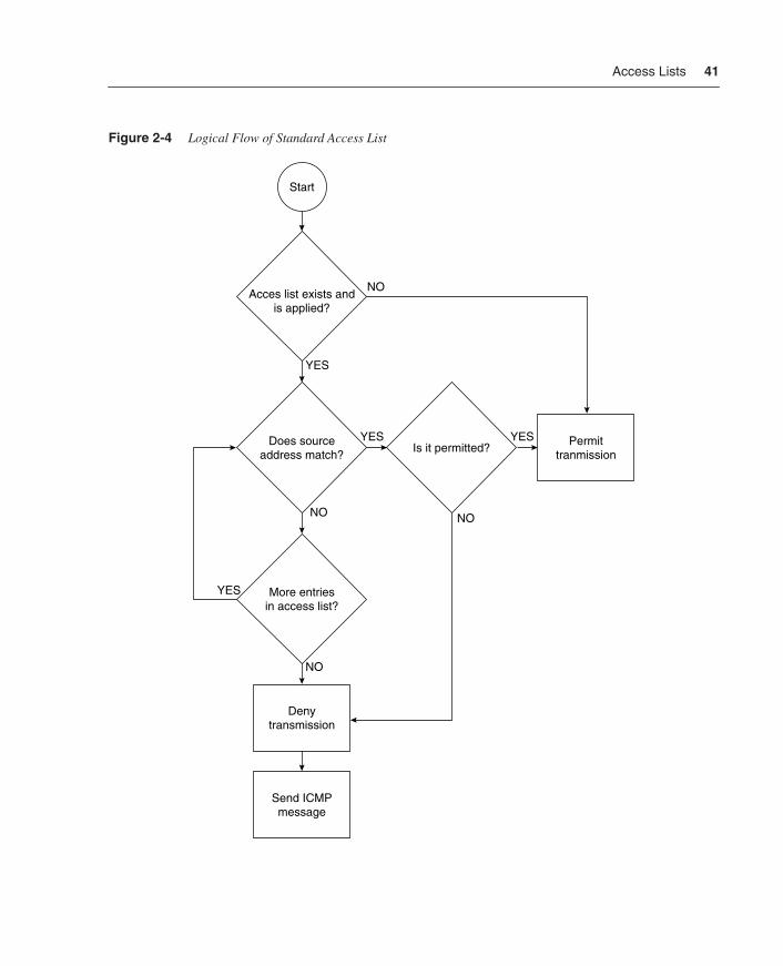
The logical flow for a standard access list is shown in Figure 2-4. Notice that if the source address is either not found or found but not permitted, the packet is denied.
Figure 2-3 Access List Limits Which Packets Travel Through a Router
An example of a standard access list follows. Although this access list will reveal some inconsistencies, it is useful for the purposes of discussion. Each line of this access list will be discussed. For the purposes of this discussion, each line is labeled with a line number:
1) access-list 3 permit 172.30.1.0 0.0.0.2552) access-list 3 permit 10.1.1.0 0.0.15.2553) access-list 3 deny 10.1.1.2 0.0.0.04) access-list 3 permit 192.168.10.0 0.0.0.75) access-list 3 deny 172.31.1.0 0.0.0.2556) access-list 3 deny any
Line 1 accomplishes a number of objectives. The keyword access-list is used to define that this line is used to specify an access list. The number 3 assigns the following permit or deny statement to access list number 3. The word permit tells the router to allow the following combination of IP address and mask through the interface. Using the keyword deny would tell the router to deny the packets.
Notice that all of the lines have an IP network address and what looks like a reversed subnet mask. The reversed subnet mask is called a wildcard mask and works very much like a subnet mask, only in reverse. In line 1, 172.30.1.0 0.0.0.255 describes the source address of packets to permit through the interface. This means that all packets with the source address of 172.30.1.0 through 172.30.1.255 will be permitted through an interface with this access list applied.
Line 2 looks similar to line 1 and allows all packets between 10.1.0.0 and 10.1.15.255 through an interface to which this access list is applied. At this point, you might be questioning exactly how that conclusion was reached. This is explained in the following sidebar, “Wildcard Masks.”
Access is denied becausethis connection is notspecifically allowed
Access is allowedbecause of entry
in access list
Router acting as a firewall with the followingaccess list applied inbound:
ip access-list 10 permit 10.2.2.0 0.0.0.255
Connection from 10.2.2.2
Connection from 10.1.1.1
Internet
SS.book Page 40 Wednesday, May 2, 2001 2:11 PM
Access Lists 41
Figure 2-4 Logical Flow of Standard Access List
Acces list exists andis applied?
Does sourceaddress match?
More entriesin access list?
Is it permitted?Permit
tranmission
Send ICMPmessage
Start
Denytransmission
YES
YES YES
NO
NO NO
NO
YES
SS.book Page 41 Wednesday, May 2, 2001 2:11 PM

42 Chapter 2: Basic Cisco Router Security
Wildcard Masks
In a wildcard mask, zeros indicate that the bit is significant while a one means that the bit is not significant for purposes of comparison. Therefore, all ones in an octet of a wildcard mask, expressed as 255, means that this octet is not significant for comparisons. If you convert the wildcard mask shown in line 2 to binary, you will receive the following:
0.0.15.255 = 00000000.00000000.00000111.11111111
There is an easy way to calculate the networks allowed or denied by wildcard masks. In this method, a subnet mask is used to determine the appropriate wildcard mask. To use this method, simply subtract the wildcard mask from 255.255.255.255. The following is an example of converting a wildcard mask to a subnet mask:
255.255.255.255 = 11111111.11111111.11111111.111111110.0.15.255 = 00000000.00000000.00000111.11111111255.255.255.255 – 0.0.15.255 = 255.255.240.0255.255.240.0 = 11111111.11111111.11111000.00000000
In the preceding, the subnet mask that is comparable to the wildcard mask is 255.255.240.0. When you apply this subnet mask to the IP address of 10.1.1.0, you calculate the network range of 10.1.0.0 through 10.1.15.255.
Line 3 is incorrect. Because an access list is read from the top to the bottom, any packet meeting this deny would have already been permitted by line 2. To correct this problem, line 3 should have been entered before line 2.
Line 4 is simply another permit statement that allows packets with a source IP address from 192.168.10.0 through 192.168.10.7 to traverse the interface. The following shows a recalculation just to be sure this is correct:
255.255.255.255 = 11111111.11111111.11111111.111111110.0.0.7 = 00000000.00000000.00000000.00000111255.255.255.255 – 0.0.0.7 = 255.255.255.248255.255.255.248 = 11111111.11111111.11111111.11111000
The subnet mask of 255.255.255.248 applied to the IP address of 192.168.10.0 provides for a range of 192.168.10.0 through 192.168.10.7.
Line 5 will deny packets with the source address of 172.31.1.0 through 172.31.1.255.
Finally, line 6 includes a technically unnecessary deny statement that will deny all sources. This is unnecessary because it is implied on an access list. However, the author recommends that it is specifically stated for clarity. Since consistency promotes understanding, the author usually adds a specific deny any to every access list. This is also an important point when working with reflexive access lists. Additionally, when using
SS.book Page 42 Wednesday, May 2, 2001 2:11 PM

Access Lists 43
extended access lists, it is possible to log matches. Logging of access lists will be explored in the later section, “Extended Access Lists.”
Applying Access ListsOnce an access list is created, it must be applied to an interface. To apply an access list to an interface, use the ip access-group or ip access-class command. The ip access-class command is used on virtual terminal interfaces, while the ip access-group command is used on all other interfaces. The access list is applied to either the inbound or outbound packets of the interface. The keywords in and out determine whether the access list is to be applied on the interface to deny inbound or outbound packets. The following is the command for applying access list number 3 to an interface to deny inbound packets. Note that you must first be in configuration mode and within the interface configuration to apply an access list.
ip access-group 3 in
The access list could alternatively be applied to the interface to deny outbound packets with the following:
ip access-group 3 out
To apply an inbound access list to a virtual terminal, the following command is used. The only difference in applying an access list between a virtual terminal and any other terminal is that the virtual terminal uses access-class instead of access-group. Again, the user must first be in configuration mode on that particular interface before applying an access list.
ip access-class 3 in
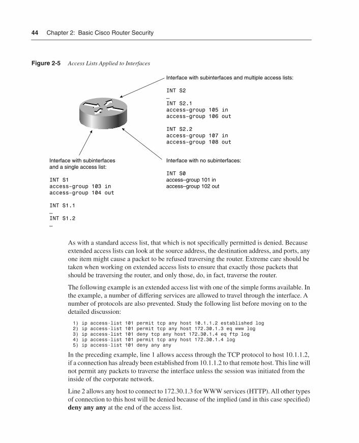
Any interface can have a single access list inbound and another single access list outbound. Only one access list should be applied in any given direction. In other words, one and only one access list should be applied inbound on an interface, and one and only one access list should be applied outbound on an interface. If an interface is using subinterfaces, such as on a serial interface connecting in a point-to-point method to remote sites, each subinterface is considered a separate interface. Each subinterface can have separate access lists. In this case, however, the root interface cannot have a separate access list. Figure 2-5 shows acceptable settings for access lists on interfaces with and without subinterfaces.
Extended Access ListsStandard access lists are limited because they make no distinctions between the ports being used. A standard access list will allow or deny packets based solely on the source IP address and are able to log only those packets that have not passed through the access list. Extended access lists overcome these limitations and form the basis for context-based and reflexive access lists, which are discussed in Chapter 5, “Cisco IOS Firewall.”
SS.book Page 43 Wednesday, May 2, 2001 2:11 PM
44 Chapter 2: Basic Cisco Router Security
Figure 2-5 Access Lists Applied to Interfaces
As with a standard access list, that which is not specifically permitted is denied. Because extended access lists can look at the source address, the destination address, and ports, any one item might cause a packet to be refused traversing the router. Extreme care should be taken when working on extended access lists to ensure that exactly those packets that should be traversing the router, and only those, do, in fact, traverse the router.
The following example is an extended access list with one of the simple forms available. In the example, a number of differing services are allowed to travel through the interface. A number of protocols are also prevented. Study the following list before moving on to the detailed discussion:
1) ip access-list 101 permit tcp any host 10.1.1.2 established log2) ip access-list 101 permit tcp any host 172.30.1.3 eq www log3) ip access-list 101 deny tcp any host 172.30.1.4 eq ftp log4) ip access-list 101 permit tcp any host 172.30.1.4 log5) ip access-list 101 deny any any
In the preceding example, line 1 allows access through the TCP protocol to host 10.1.1.2, if a connection has already been established from 10.1.1.2 to that remote host. This line will not permit any packets to traverse the interface unless the session was initiated from the inside of the corporate network.
Line 2 allows any host to connect to 172.30.1.3 for WWW services (HTTP). All other types of connection to this host will be denied because of the implied (and in this case specified) deny any any at the end of the access list.
Interface with subinterfaces and multiple access lists:
INT S2…INT S2.1access–group 105 inaccess–group 106 out
INT S2.2access–group 107 inaccess–group 108 out
Interface with no subinterfaces:
INT S0access–group 101 inaccess–group 102 out
Interface with subinterfacesand a single access list:
INT S1access–group 103 inaccess–group 104 out
INT S1.1…INT S1.2…
SS.book Page 44 Wednesday, May 2, 2001 2:11 PM
Password Management 45
Line 3 denies access to host 172.30.1.4 if the remote host is trying to connect using FTP services. Line 4 allows all other types of connections to 172.30.1.4.
Notice that each of these lines has the word log added at the end of the line. This causes the router to log all attempts at connection. A standard access list using the log option will only log those packets that have been denied.
Named Access ListsNamed access lists, first introduced in IOS Version 11.0, allow the administrator to use a character string instead of an access list number. One benefit is that the limitations of 99 standard access lists (1–99) and 100 extended access lists (100–199) no longer apply. The administrator can also name an access list something meaningful. For example, an access list named “from-internet” could be created to limit access into the corporate network from the Internet. Naming access lists in a meaningful way tends to make troubleshooting easier.
Another advantage to named access lists is that entries can be removed. However, new entries are still added to the bottom of the access list, which is usually not what is intended.
Reflexive access lists, discussed in Chapter 5, require a named access list, and access lists dealing with packet filters and route filters cannot use named access lists. A standard and an extended access list cannot both have the same name.
Password ManagementPasswords are the primary defense against unauthorized access to networking equipment. The best way to prevent unauthorized access is to use either a TACACS+ or a RADIUS authentication server. Even if you are unable to use these services, some basic configuration issues should be addressed concerning password management.
The first issue to be addressed is choosing passwords. No matter what type of encryption is used, some general rules should be followed. When a password is being chosen, the following list will help the administrator in determining the appropriateness and the treatment of passwords:
• Passwords should not reflect the company name.
• Passwords should not reflect the business of the company.
• Passwords should not reflect the equipment where they are used.
• Passwords should not be decipherable based on any other configuration parameter. This includes model number and network address.
• Passwords should not be any word that appears in a standard dictionary.
• Passwords should be unique.
• Passwords should not be sequential.
SS.book Page 45 Wednesday, May 2, 2001 2:11 PM
46 Chapter 2: Basic Cisco Router Security
• Passwords should include both uppercase and lowercase characters and nonalphabetic characters if possible.
• Passwords should be as long as reasonably possible.
• Passwords should be changed on an irregular basis.
• Any list containing passwords should be closely guarded.
• Critical passwords should be changed whenever any person with that level of access leaves the company. This holds especially true if a contractor is involved or if a person was terminated involuntarily.
• As few people as possible should have access to passwords, but critical passwords should always be known by more than one person. This is an exception to the generally accepted rule that passwords should not be shared.
• Nontechnical managers generally do not and should not know system passwords. Knowing a password without knowing how to effectively configure equipment serves no legitimate purpose.
• Passwords should not be distributed over the Internet.
Although some of the preceding guidelines might seem overly restrictive, they are designed to reduce the severity of a security breach, as well as to prevent breaches from happening. For example, the author has seen companies that set router passwords based on the serial IP address. If a single router was penetrated, the password scheme would quickly become apparent. When you don’t use a common password scheme, someone trying to break into your network will need to start over with every device.
The next sections examine how passwords are set with the enable password and enable secret commands. Then the chapter moves on to console passwords and AAA (authentication, authorization, and accounting) password management.
The enable password CommandThe enable password command is an old command that is not considered secure and therefore should not be used. When enable password is combined with the service password-encryption command, the IOS encrypts the entered password using the Vigenere algorithms. These were never intended to prevent any but the most casual observer from gaining access. Any dedicated or fairly knowledgeable person can easily break this algorithm. A number of programs are also available on the Internet that allow you to break a password that is entered using the enable password command. The enable password command can be disabled with the use of the following global configuration command:
no enable password
SS.book Page 46 Wednesday, May 2, 2001 2:11 PM
Physical Security 47
The enable secret CommandUsing the enable secret command in conjunction with the service password-encryption command provides a decent level of decryption resistance. In this case, MD5 hashing is used to encrypt the password. Although there have been no known cases of MD5 hashing being decrypted as of the time of this writing, there are other ways in which an enable secret password can be broken. The easiest way to break an enable secret password is by using a brute-strength dictionary attack, where a list of words is compiled (the dictionary) and then each word is used as the password sequentially. Dictionary attacks are the reason for the guideline against using any word that appears in a dictionary.
The enable secret command allows the administrator to specify up to 16 privilege levels through the use of numbers 0 through 15. If no level is specified, level 15 is assumed. This command, combined with the privilege level command, allows the administrator to give some administrators access to specified commands while denying access to others. The full syntax of the enable secret command is
enable secret [level level] {password | encryption-type encrypted-password}
The following example shows how to enable a secret password at level 7 using “9%ad100gbellisnon” for the password. The second line starts service password-encryption.
RouterA(config-if)#enable secret level 7 9%ad100gbellisnonRouterA(config-if)#service router-encryption
The optional encryption-type and encrypted-password are used when copying previously encrypted passwords from other router configurations. Currently, the only encryption type available is MD5, which is specified with the number 5. This allows the administrator to copy configurations with an enable secret password across multiple routers. Although having the same password on multiple routers should usually be avoided, there are some circumstances, such as during initial deployment, where it is acceptable.
The command service router-encryption is used in the preceding example to ensure that all passwords in the configuration are shown encrypted. Before this command is entered, all passwords other than the enable secret password are shown exactly as they are entered. When the service router-encryption command is used, all passwords within the configuration are encrypted. This prevents revealing the password when distributing printed copies of the configuration.
Physical SecurityPhysical security should always come first in the mind of the security administrator. If you cannot guarantee physical security, you cannot guarantee any security. This is especially true where the console and auxiliary ports of a router are concerned. Anyone with physical access to a Cisco router and who possessed a PC, the proper cable, and the required knowledge can break into your router. Using the password recovery techniques that are
SS.book Page 47 Wednesday, May 2, 2001 2:11 PM
48 Chapter 2: Basic Cisco Router Security
widely published by Cisco will allow someone to gain total control of the router. If you set all of your router passwords to be the same or used a logically based scheme for router passwords, your entire network is now open to the will of the intruder.
Physical security deals with restricting physical access to equipment. Locking equipment-room doors, requiring employee badges, and moving routers to their own secure room is the basis for physical security.
Although you cannot prevent people who are authorized to enter the room with the router from rebooting and changing the password, you can limit what they are able to accomplish by merely connecting into the console port or by using Telnet to access the router.
One good method of preventing casual hackers from gaining access to the console port is to physically disconnect the console port from the router’s motherboard. This requires the router case to be opened. This is really the equivalent of hiding a door key under the doormat; it will not stop any but the most casual hacker. Anyone opening the case to the router will quickly see that the console port is disconnected. However, this method is better than not securing the console port in any way. Chapter 9, “Cisco Secure Access Control Server (ACS),” deals with how to use AAA to ensure that console port access is truly secure.
Another method is to change the connection properties to an unusual value. This will require someone who is casually trying to connect to the console port to set something other than the defaults. At this point, it becomes a guessing game for the hacker.
Although neither of these methods is foolproof, they do provide some additional security. The only true method of preventing someone from accessing the router through the console port is to physically lock the router in a room where no unauthorized personnel have access.
Controlling Line AccessLine access can easily be controlled on a Cisco router. Lines—consisting of console ports, auxiliary ports, and Telnet ports—all have the ability to limit the users who can gain access.
Adding an access list to the vty (Telnet) ports is relatively easy. First, a standard access list (numbered 1–99) is defined as follows:
access-list 8 permit 172.30.1.45access-list 8 permit 10.1.1.53access-list 8 deny any
This access list allows only hosts with one of two IP addresses to Telnet into the router. After creating the access list above, you still need to apply that access list to an interface. Applying an access list to a line uses the access-class command instead of the access-group command that is commonly used at the interface level. When applying the access list to the Telnet ports, use the following commands:
line vty 0 4access-class 8 in
SS.book Page 48 Wednesday, May 2, 2001 2:11 PM
Out-of-Band Management Security 49
An access list can also be applied to one of the lines to limit where a connected user can Telnet. Using a standard access list and applying it to the outbound interface will limit Telnet sessions. An example follows:
access-list 9 permit 172.30.1.45access-list 9 permit 10.1.1.53access-list 9 deny any
line vty 0 4access-class 9 out
In this case, the user can Telnet to only one of the two listed IP addresses. This might seem like a useless command set at first, because an administrator can simply remove this access list. However, depending on which level of authentication the administrator logged on with, he or she might not have the ability to configure the router. In the earlier section regarding the enable secret command, you learned that a privilege level could have an associated password. Every secret level can have its own password, and the administrator has the ability to limit functionality of each level. The privilege exec command is used to do this. Assume that you want to limit a new junior administrator to be able to use only the show commands. This can be accomplished with the following lines:
enable secret level 6 110%gdfsfejprivilege exec 6 show
In the preceding example, logging on with the level 6 password allows the user to access only the show commands. Limiting which administrators know passwords allows you to control how much access the administrators have.
Unfortunately, because the console and auxiliary ports are directly connected to the router, it is impossible to add an access list to these interfaces. Other configuration options are available, such as TACACS+ and RADIUS authentication. Both of these techniques are covered in Chapter 9. However, limiting the ability to administer the router through the use of enable levels, as shown in this section, helps to control the amount of damage an inexperienced administrator can cause.
On all of the line interfaces, you should specifically set a timeout parameter. If there is no activity on the line for a period of time, which is specified in minutes and seconds, the connection will automatically disconnect. This makes it harder for a terminal that has been left unlocked to become a security breach. You can set a timeout parameter for 5 minutes and 0 seconds with the following command:
exec-timeout 5 0
Out-of-Band Management SecurityOut-of-band security can pose unique problems for the administrator. By definition, out-of-band access bypasses all of the security measures that are put into place throughout the network. Out-of-band management is the ability to configure a piece of equipment by a means other than the transmission media used for transferring data. For example, if a
SS.book Page 49 Wednesday, May 2, 2001 2:11 PM

50 Chapter 2: Basic Cisco Router Security
remote site used Frame Relay for connectivity, using an ISDN dial-up or modem connection for management purposes is considered out-of-band. The easiest way to avoid all out-of-band security issues is simply not to allow any out-of-band access. In most cases, however, there are legitimate reasons to allow such access. The primary reason is to enable troubleshooting and repairs from a remote location when the primary link fails.
When using out-of-band connections, be especially aware that there is usually only a single line of defense between the outside world and the interior of your network. Because out-of-band management usually bypasses firewalls, perimeter routers, and other security measures, extra precautions must be employed to ensure that the out-of-band management connections do not present a new opportunity for security breaches.
If at all possible, combine all available methods of access limitation, logging, and authentication on out-of-band access points. Out-of-band telephone numbers should be guarded in a similar fashion as passwords. If it is possible to limit access to predefined telephone numbers and to use a callback method of authentication, you should do so.
One possible way of remotely managing equipment combines out-of-band management with existing equipment. For instance, assume that administrators need to access equipment on the local network from their homes. In this case, using an existing access server to connect to the local network and then using Telnet to connect to the equipment in question combines both in-band and out-of-band management. The advantage of this method is that the entry points to the network are concentrated, presenting a smaller opportunity for security breaches, and that the strongest security methods including call back and AAA services may be applied at this entry point. When feasible, using a combination of services as described in this paragraph increases security and lessens the routine maintenance required.
See the section “Physical Security” earlier in this chapter for specifics on configuring access lists and other security methods so that interfaces can be set in the most secure manner.
Cisco Discovery Protocol (CDP)Cisco Discovery Protocol (CDP) uses Layer 2 inquiries to find information about neighboring devices. CDP, enabled by default on IOS versions 11 and later, is extremely useful for both managing and troubleshooting devices. However, CDP has an inherent flaw: it will answer any device that sends the proper request. Because CDP information contains such items as the IOS version number, the name of the device, the network address of the device, and how that device is connected, the administrator should limit on which interfaces CDP packets are answered and sent.
If CDP is not being used internally on the network, it can be disabled with the following global command:
no cdp run
If CDP is required on the interior of the network, the administrator should still disable CDP on all external interfaces. To disable CDP on any given interface, enter the following interface command:
no cdp enable
SS.book Page 50 Wednesday, May 2, 2001 2:11 PM
Hypertext Transfer Protocol (HTTP) Configuration Services 51
Hypertext Transfer Protocol (HTTP) Configuration Services
Many Cisco devices allow the use of a Web browser for configuration and monitoring. Although this method of configuration might be convenient, especially for the new administrator, special considerations are required to ensure security. HTTP services are also used on the Cisco 1003, 1004, and 1005 routers for use with the Cisco IOS ClickStart software.
Access lists must be used on perimeter routers to limit who can access a router from outside of the local network. If HTTP services are used, you need to adjust access lists to allow only specific IP addresses access to routers through WWW services.
HTTP services are turned on with the ip http server command. Use the no form of the command to disable this service. HTTP services run by default on TCP port 80; this can be changed to virtually any port required. It is recommended that you change the default port. Changing from the default port of 80 requires a hacker to know which port is in use before being able to exploit any possible security holes.
Control over who accesses the HTTP services is managed by a standard access list, as well as by the ip http access-class command. Note that unlike other access-class commands, the ip http access-class command is entered in the global configuration mode. Additional security can be achieved through AAA authentication, which is covered in Chapter 10. If AAA authentication is not used, the enable password is used for logging onto the router.
The following is an example of setting HTTP services on a router, creating and applying an access list, and adding AAA authentication. Note that all commands are entered in the global configuration mode. Also note that the use of an exclamation mark (!) at the beginning of a line indicates that the line is a comment.
ip http server!Starts HTTP services on the router.!Services can be stopped with the no ip http services command.
ip http port 10120!This changes the port used for management from port 80 to port 10120.!Port 10120 was an arbitrary number chosen because it is not commonly used.!To change the port back to 80, use the no ip http port command.
access-list 91 permit host 10.1.1.50!Allow host 10.1.1.50 access.access-list 91 permit host 10.1.1.52!Allow host 10.1.1.52 access.access-list 91 deny any any!Deny all others. This line is included for clarity.!All access lists have an implied deny all at the end.
ip http access-class 91!Apply access list 91 to HTTP services.
ip http authentication aaa tacacs!Use TACACS for authentication.
SS.book Page 51 Wednesday, May 2, 2001 2:11 PM

52 Chapter 2: Basic Cisco Router Security
Simple Network Management Protocol (SNMP)Simple Network Management Protocol (SNMP) is used by a variety of programs involved with network management. The beauty of SNMP is intertwined with its dangers. Because SNMP is designed to allow an administrator to monitor and configure devices remotely, SNMP can also be used in attempts to penetrate the corporate network. This section explores how to minimize vulnerability while using SNMP.
A few simple configuration changes, as well as a few logical choices that should be made by the administrator, can greatly reduce the risks involved with SNMP. Both logical choices and configuration considerations are covered in this section.
The first consideration an administrator should make regarding SNMP is to turn it off. If SNMP is not being used, running it only takes away from available bandwidth, needlessly burns CPU cycles, and exposes the network to unnecessary vulnerabilities.
Before using SNMP in read/write mode, rethink the requirement to do so. Running SNMP in read/write mode with just a few minor configuration errors can leave the whole of your network susceptible to attacks. A great number of tools can scan any network over SNMP. These can map out your entire network if SNMP has a hole left open.
In late February of 2001, Cisco released information that there are also security issues with SNMP even when using only the read mode. Due to a defect within the Cisco IOS versions 11.0 and 12.0, SNMP is vulnerable to certain denial of service attacks designed to confuse products such as CiscoWorks. In order to fix these potential security problems, an IOS upgrade must be accomplished. If you have not upgraded your IOS since this time, it is strongly recommended that you read the information at the following two URLs to see if your specific equipment is affected:
www.cisco.com/warp/public/707/ios-snmp-ilmi-vuln-pub.shtml
www.cisco.com/warp/public/707/ios-snmp-community-vulns-pub.shtml
SNMP is available in versions 1, 2, and 3. There are some major differences between versions. First, version 1 sends passwords in clear-text format, and version 2 allows password encryption using the MD5 encryption algorithms. Second, although virtually all management programs can use SNMP version 1, the choice is limited when using SNMP version 2. One of the original goals of version 2 was to provide commercial-grade security through authentication, privacy, and authorization. Version 2 failed to accomplish these goals because version 2c, while having the endorsement of the Internet Engineering Task Force (IETF), failed to implement these security measures. Versions 2u and 2* implemented security but failed to gain acceptance from the IETF.
Version 3, available on the standard Cisco IOS since release 12.0(3)T, uses MD5, Secure Hash Algorithm (SHA), and keyed algorithms to protect against data modification and masquerade attacks. Version 3 can optionally use Data Encryption Standard (DES) in the cipher block chaining mode when security is required.
SS.book Page 52 Wednesday, May 2, 2001 2:11 PM

Simple Network Management Protocol (SNMP) 53
From a security viewpoint, the passing of clear-text passwords should become a primary concern, especially because most SNMP applications send passwords repeatedly during normal operations. If your management software and equipment is compatible with version 2, there is no reason to run version 1. Assuming that the network in question is using only SNMP version 2, the administrator can ensure encryption by using the following command:
snmp-server enable traps snmp authentication md5
This command replaces the older and no longer valid command:
snmp-server trap-authentication
Unless you are purposely using SNMP version 1, the following command must be avoided at all costs:
snmp-server communityname
This command not only sets the community name, but also enables SNMP version 1 instead of version 2.
If version 1 is running, pay close attention to the name of the community. Because the community name is passed in clear text, this name should give no indication of either the company name or the type of company associated with the name. For example, assume that the company in question is Cisco Systems. Using the word “cisco” in any part of the community name might alert hackers that they have gained access to Cisco Systems. Using a community name “routers” might also give hackers unnecessary information. When using SNMP version 1, Cisco suggests that all equipment use differing community names. Although this might seem like an unreasonable restriction in a large network, using multiple community names will reduce the number of routers that are vulnerable because of the revealing of a single community name. If it is not possible to assign a different community name for all devices, find a balance between using a single community name and using a differing name on each piece of equipment. Finally, avoid using the names “public” or “private,” because they are so commonly used.
Most networks have a few select management stations from which SNMP messages can legitimately originate. When using version 1 and the community name command, it is recommended that the optional access list number be included. This allows the administrator to control which stations have access, through a standard access list (numbered 1–99) applied to the SNMP services as if SNMP were an inbound router port.
Access control lists (ACLs) should be placed close to the edge of your network, preventing outside parties from probing your network over SNMP. Additionally, if the CPU cycles are available on interior routers, it might be worth the effort to add ACLs on certain routers in the interior of the network. This allows for the limitation of breaches, if they do occur.
SS.book Page 53 Wednesday, May 2, 2001 2:11 PM
54 Chapter 2: Basic Cisco Router Security
If you are using SNMP in read-only mode, you need to ensure that it is set up with appropriate access controls. An example of proper protection follows:
access-list 7 permit 172.30.1.45access-list 7 permit 10.1.1.53
snmp-server community 85tres76n RO 7snmp-server trap-source Loopback0snmp-server trap-authenticationsnmp-server enable traps configsnmp-server enable traps envmon
snmp-server contact Joe Admin [[email protected]]snmp-server location main server room router 8snmp-server enable traps bgpsnmp-server enable traps frame-relaysnmp-server host 172.30.1.45 85tres76nsnmp-server host 10.1.1.53 85tres76nsnmp-server tftp-server-list 7
The preceding example uses ACL 7 and allows SNMP messages from only two IP addresses to be accepted. Because there are only two possible SNMP servers (172.30.1.45 and 10.1.1.53), these are the only IP addresses where SNMP is allowed to respond. SNMP messages from all other IP addresses would be implicitly denied.
Because the community string is not encrypted, care is taken to use “85tres76n,” which has no known relation to the company or the services that the company offers. Once a community string is known outside of the organization, a point of possible attack is created. Unless SNMP is set up to pass community-name authentication failure traps, and the SNMP management device is configured to react to the authentication failure trap, the community name is easily discovered.
Keep in mind that accepting SNMP from only known good IP addresses does not necessarily guarantee security because of IP address spoofing. Unless serious antispoofing measures are in place, you cannot rely on IP addresses as the primary means of security on any system. With all security configurations, the objective of the administrator should be to build many obstacles to unauthorized personnel while providing seamless operation to authorized users.
Notice that even the e-mail address of the administrator is not a company e-mail address. This is done in case the SNMP does become violated. If the SNMP system is violated, this information could give clues about the company name to the violator.
The snmp-server host configuration shown in the preceding example lists the hosts to which SNMP information can be sent. If a means of collecting SNMP traps is not available, don’t configure snmp-server hosts. When using an SNMP server host, make sure that this host is configured to receive and respond to SNMP traps. Read/write community strings should not be used on networks in order to limit the risk of SNMP sets being used by unauthorized parties.
SS.book Page 54 Wednesday, May 2, 2001 2:11 PM
Network Time Protocol (NTP) 55
Network Time Protocol (NTP)The Network Time Protocol (NTP) allows for time synchronization of equipment on the network. As commonly used, one router is set as the master to which other devices look for the current time. If the current time is different than the time received from the master time device, the time is adjusted accordingly. The master device also looks at a known time source. This time source may be a local device, a radio device connected locally, or a publicly available device on the Internet. Cisco’s implementation of NTP allows for the delay that the packet carrying the current time experiences while crossing the Internet. By having all the devices synchronized to one clock, understanding an outage on a network is easier. By examining logs that have been time-stamped by one common time, the order in which events occurred can be determined, and the outage thus isolated to the proper culprit.
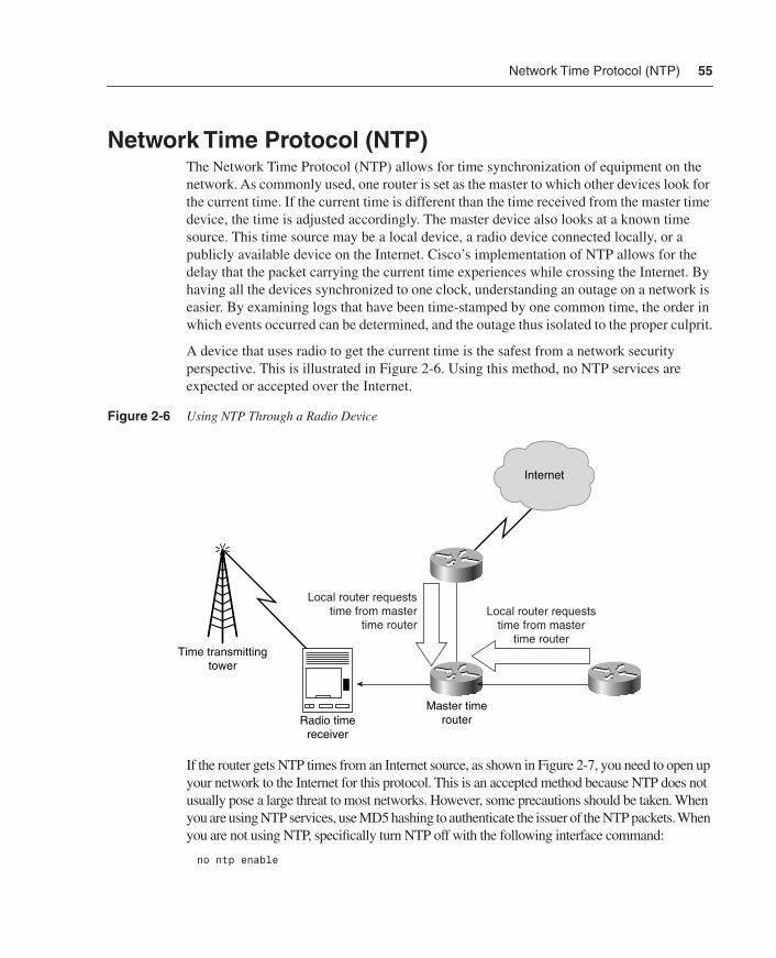
A device that uses radio to get the current time is the safest from a network security perspective. This is illustrated in Figure 2-6. Using this method, no NTP services are expected or accepted over the Internet.
Figure 2-6 Using NTP Through a Radio Device
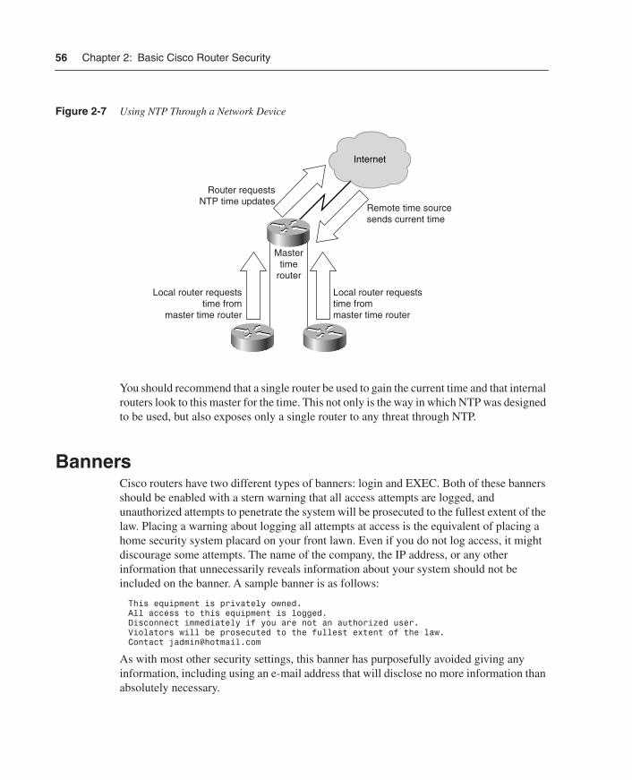
If the router gets NTP times from an Internet source, as shown in Figure 2-7, you need to open up your network to the Internet for this protocol. This is an accepted method because NTP does not usually pose a large threat to most networks. However, some precautions should be taken. When you are using NTP services, use MD5 hashing to authenticate the issuer of the NTP packets. When you are not using NTP, specifically turn NTP off with the following interface command:
no ntp enable
Internet
Local router requeststime from master
time routerLocal router requests
time from mastertime router
Time transmittingtower
Radio timereceiver
Master timerouter
SS.book Page 55 Wednesday, May 2, 2001 2:11 PM
56 Chapter 2: Basic Cisco Router Security
Figure 2-7 Using NTP Through a Network Device
You should recommend that a single router be used to gain the current time and that internal routers look to this master for the time. This not only is the way in which NTP was designed to be used, but also exposes only a single router to any threat through NTP.
BannersCisco routers have two different types of banners: login and EXEC. Both of these banners should be enabled with a stern warning that all access attempts are logged, and unauthorized attempts to penetrate the system will be prosecuted to the fullest extent of the law. Placing a warning about logging all attempts at access is the equivalent of placing a home security system placard on your front lawn. Even if you do not log access, it might discourage some attempts. The name of the company, the IP address, or any other information that unnecessarily reveals information about your system should not be included on the banner. A sample banner is as follows:
This equipment is privately owned.All access to this equipment is logged.Disconnect immediately if you are not an authorized user.Violators will be prosecuted to the fullest extent of the law.Contact [email protected]
As with most other security settings, this banner has purposefully avoided giving any information, including using an e-mail address that will disclose no more information than absolutely necessary.
Internet
Local router requeststime from
master time router
Local router requeststime frommaster time router
Mastertime
router
Router requestsNTP time updates
Remote time sourcesends current time
SS.book Page 56 Wednesday, May 2, 2001 2:11 PM

Recommended Minimum IOS Security Settings 57
Recommended Minimum IOS Security SettingsThis section deals with the basic minimum configurations that all enterprises should employ on their routers. Although some of the commands explained in this section are disabled by default, the administrator is urged to deny specifically those services and routes that are not needed. The following topics are covered:
• Denying RFC 1918 routes
• UDP and TCP servers
• Finger service
• IP unreachables
• ICMP Redirect messages
• Directed broadcasts
• Proxy Address Resolution Protocol (ARP)
• IP Unicast
• IP source routing
Denying RFC 1918 RoutesAll border routers within a company that is concerned with security should have some specific routes denied. RFC 1918 defines the ranges of IP addresses available for use on the Internet, as well as those considered private. A private IP address should not be used on the Internet. The source or destination addresses of all packets on the Internet should not be within these private ranges. Common attack methods rely on private addresses to hide the true source of the attack. This section shows a typical method of blocking access from these forms of attack. With the exception of Network Address Translation (NAT), no one from the Internet or from within your own network should be sending packets from any of the addresses in the following list. The following is a sample ACL that will be applied to routing updates to prohibit the private address spaces as defined by RFC 1918:
access-list 191 deny ip host 0.0.0.0 any!This prevents packets with a source address of 0.0.0.0!from traversing the networkaccess-list 191 deny ip any host 0.0.0.0access-list 191 deny ip 10.0.0.0 0.255.255.255 any!10.0.0.0 through 10.255.255.255 is a non-routable address range!and should not traverse the network from the Internet.access-list 191 deny ip 127.0.0.0 0.255.255.255 any!127.0.0.0 through 127.255.255.255 addresses are used for loopback testing!and should never traverse the Internet.access-list 191 deny ip 169.254.0.0 0.0.255.255 any!169.254.0.0 is reserved by Microsoft as the address given to a host!unsuccessfully attempting to use DHCP services.access-list 191 deny ip 172.16.0.0 0.15.255.255 any!172.16.0.0 through 172.31.255.255 are non-routable addresses.
SS.book Page 57 Wednesday, May 2, 2001 2:11 PM

58 Chapter 2: Basic Cisco Router Security
access-list 191 deny ip 192.168.0.0 0.0.255.255 any!192.168.0.0 through 192.168.255.255 are non-routable addresses!and should never be traveling over the Internet.access-list 191 deny ip 224.0.0.0 31.255.255.255 224.0.0.0 31.255.255.255!224.0.0.0 through 255.255.255.255 as a source address is invalid!because these are reserved for multicast broadcasts.!Here, you are stopping these packets from traversing the network if the!destination is a multicast and the source is a multicast.!A correctly formed multicast packet will have a valid source address!with a multicast destination address between 224.0.0.0 and 255.255.255.255.access-list 191 deny ip any 255.255.255.0 0.0.0.255!Packets should not be sent to the 255.255.255.0 network,!because this is a reserved network.access-list 191 permit ip any any!You need to allow traffic that is not specifically blocked!through the router.deny any any!The deny any any line is shown for clarity.!This line is implied by all access lists.!Any packets that are not specifically allowed are denied.
This access list should be applied to both the inbound and outbound interfaces of border routers. If you are running NAT services, some of these interfaces will not necessarily apply. For example, if you are using the 10.0.0.0 network inside your organization, you will need to allow this network to travel to the device providing NAT services. Additionally, on the inbound interface of all border routers, the internal network addresses should be specifically denied. The preceding list is a minimum list that is designed to prevent commonly spoofed IP addresses from being allowed to traverse your network. If other routes are known to be invalid, they should also be prohibited. Besides specifically preventing packets with a source address matching your internal network from entering through the Internet, administrators should consider ways in which they can prohibit unauthorized external network addresses from traversing to the outside of the network. This will help prevent someone from using the network to launch an attack on a third party.
As with all access lists, these might cause excessive CPU usage on routers. However, the additional CPU usage is usually justified by the added security provided by the access lists. If your router is unable to effectively function with the preceding access lists, chances are that the router is already overworked and should be upgraded.
User Datagram Protocol (UDP) and Transmission Control Protocol (TCP) Servers
The User Datagram Protocol (UDP) and Transmission Control Protocol (TCP) servers are generally those with port numbers below 10. These typically include echo ports and discard ports. Echo ports replay the packet (echo) out of the port received. Discard throws away the packet. Because either throwing away or echoing packets consumes CPU cycles, they are commonly used in denial of service (DoS) attacks. When too many packets requesting echoes overload a router, for example, the router must delay other processes. This delay can cause problems, such as an inability to process routing updates. Therefore, both of these
SS.book Page 58 Wednesday, May 2, 2001 2:11 PM
Recommended Minimum IOS Security Settings 59
should be disabled unless there is a specific reason to run them. This is especially important on the router directly connected to the Internet. These can be disabled as follows:
no service-udp-small-serversno service-tcp-small-servers
Finger ServiceThe finger service can be used to resolve usernames on remote systems. Specifically, finger was designed to show active users on a system. Although the prevalence of finger has been reduced in the last few years, several administrators still allow finger requests to traverse their networks. Because of the many known ways that finger can be abused, no router should ever run finger unless there is a very specific reason to do so. An administrator can (and should) stop finger services with the following command:
no service finger
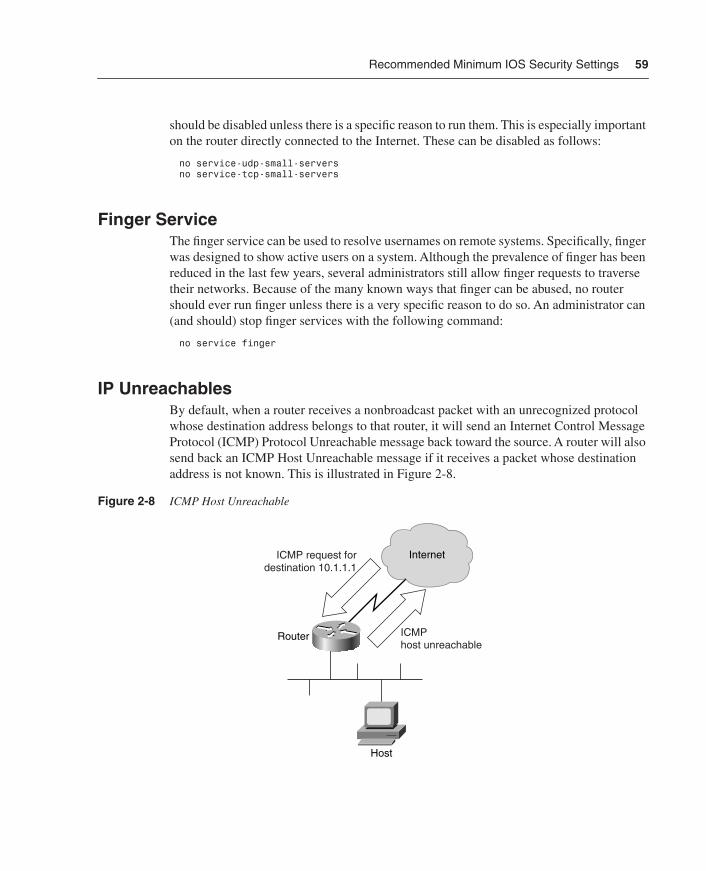
IP UnreachablesBy default, when a router receives a nonbroadcast packet with an unrecognized protocol whose destination address belongs to that router, it will send an Internet Control Message Protocol (ICMP) Protocol Unreachable message back toward the source. A router will also send back an ICMP Host Unreachable message if it receives a packet whose destination address is not known. This is illustrated in Figure 2-8.
Figure 2-8 ICMP Host Unreachable
InternetICMP request fordestination 10.1.1.1
ICMPhost unreachable
Router
Host
SS.book Page 59 Wednesday, May 2, 2001 2:11 PM
60 Chapter 2: Basic Cisco Router Security
Although this behavior might seem reasonable, it also opens the router to vulnerability from ICMP DoS attacks. If a router spends all of its time responding to ICMP messages, something else is not being processed. Additionally, disabling ICMP unreachables might help out the innocent victim of a DoS attack.
A DoS attack can occur in many ways. Here is just one scenario: When sending an ICMP echo request, the perpetrator changes the originating IP address on the packet to a legitimate IP address of the victim. The perpetrator sends numerous ICMP requests to the network broadcast address of the bystander. The bystander, who is unaware of what is occurring, responds to these ICMP requests. The response is sent to the IP address within the original request. If the source address is valid, some router will start receiving these responses. Take a moment to look at Figure 2-9.
In this case, the ICMP requests were sent to the broadcast network address on the bystander’s network. Each host on the network received the request and responded. This means that the bystander amplified the power of the effectiveness of the requests by the number of hosts responding. Very quickly, the bystander’s available bandwidth will be used by ICMP messages. The victim’s bandwidth will also be used by these ICMP messages. In effect, both the victim and the bystander lose all effective communication capabilities. It becomes very hard to tell exactly who the intended victim is in this case. If the perpetrator sends out requests to more than one bystander at a time, the effect can be devastating to the victim.
It is recommended that all external interfaces be configured not to respond in this manner. Preventing a router from sending out ICMP Host and Protocol Unreachable messages is easily accomplished with the following interface command:
no ip unreachable
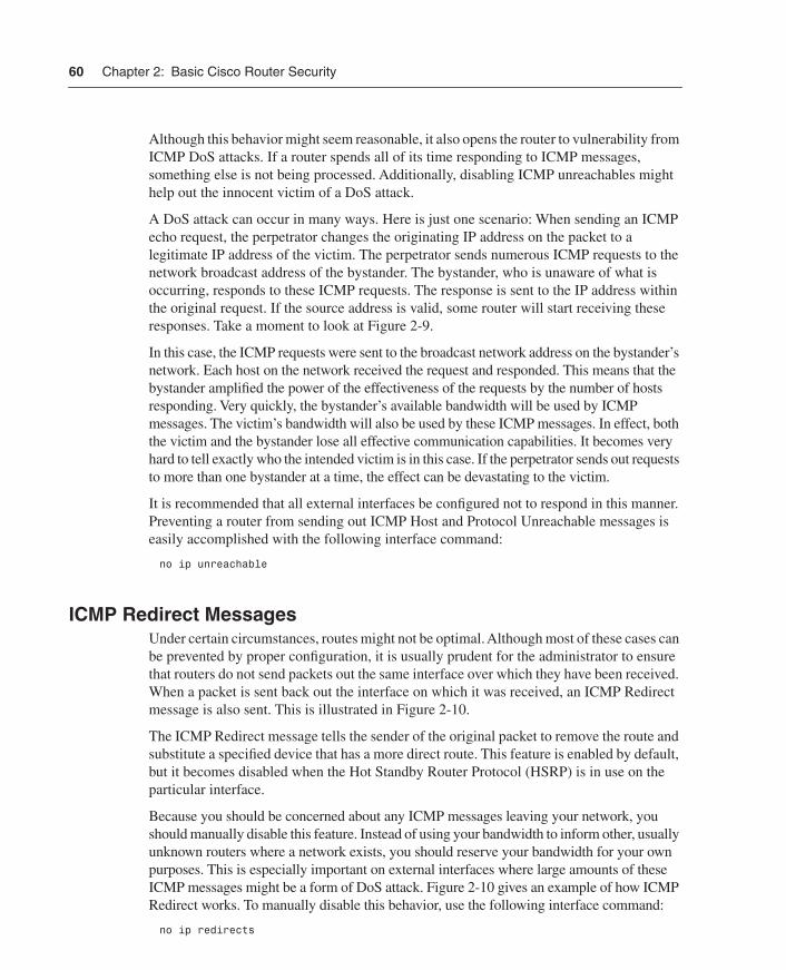
ICMP Redirect MessagesUnder certain circumstances, routes might not be optimal. Although most of these cases can be prevented by proper configuration, it is usually prudent for the administrator to ensure that routers do not send packets out the same interface over which they have been received. When a packet is sent back out the interface on which it was received, an ICMP Redirect message is also sent. This is illustrated in Figure 2-10.
The ICMP Redirect message tells the sender of the original packet to remove the route and substitute a specified device that has a more direct route. This feature is enabled by default, but it becomes disabled when the Hot Standby Router Protocol (HSRP) is in use on the particular interface.
Because you should be concerned about any ICMP messages leaving your network, you should manually disable this feature. Instead of using your bandwidth to inform other, usually unknown routers where a network exists, you should reserve your bandwidth for your own purposes. This is especially important on external interfaces where large amounts of these ICMP messages might be a form of DoS attack. Figure 2-10 gives an example of how ICMP Redirect works. To manually disable this behavior, use the following interface command:
no ip redirects
SS.book Page 60 Wednesday, May 2, 2001 2:11 PM

Recommended Minimum IOS Security Settings 61
Figure 2-9 ICMP Redirect Affects Both Bystander and Victim
Figure 2-10 ICMP Redirect DoS Attack
Bystander
Victim
Internet
Perpetrator
HostHost
Step #1Single ICMP echo request sent to10.1.1.255
10.1.1.1/24network
Step #2Each host receivesICMP echo request thenresponds with an echo reply
Step #3The whole network of thebystander responds with an echo reply
This overwhelms both the bystanderand the victim networks
InternetPacket destined forknown external address
Packet destined forknown external address
ICMP redirectRouter
Host
SS.book Page 61 Wednesday, May 2, 2001 2:11 PM

62 Chapter 2: Basic Cisco Router Security
Directed BroadcastsIt is possible within the IP protocols to send a directed broadcast, which is when a packet that is received contains a request to translate the broadcast packet to another interface on the device, usually the LAN interface. If this is left enabled, the LAN might experience excessive broadcasts from a DoS attack. The default on IOS 12.0 and later is to have directed broadcasts disabled. However, the administrator should still specifically disable it with the following command:
no ip directed-broadcast
Proxy Address Resolution Protocol (ARP)Proxy Address Resolution Protocol (ARP) is a system where one device answers an ARP request destined for another device if that MAC address is known. When a proxy ARP device sees an ARP request for a device on a different known Layer 3 network, the proxy ARP device will reply to the ARP and forward the request to the remote LAN segment. This is usually done so that ARP requests will not have to travel over a relatively slow link. The problem with using proxy ARP is that it can expose the network to potential security problems. One way of exploiting the security hole caused by proxy ARP is to launch a DoS attack that uses bandwidth and router resources responding to repeated ARP requests. Figure 2-11 illustrates this attack.
Figure 2-11 Proxy ARP DoS Attack
Proxy ARP can be disabled with the global command:
no ip proxy-arp
Bystander
Victim
Internet
Perpetrator
HostHost
Step #1Repeated ARPrequests for data frombystander network
10.1.1.1/24network
Step #3The bystander receives forwarded ARP request and replies to the sender (victim) router
This overwhelms the resources of thevictim as well as using a smalleramount of resources on the bystander
Step #2Victim router uses CPU and memory resources as wellas Frame Relay bandwidthforwarding request to thebystander's network
SS.book Page 62 Wednesday, May 2, 2001 2:11 PM

Recommended Minimum IOS Security Settings 63
IP VerifyThe ip verify unicast reverse-path command is useful in preventing address-spoofing attacks on systems running Cisco Express Forwarding (CEF) and IOS version 12.0 and higher. While running CEF with this interface level command, all packets are evaluated for the source address. If the source IP address does not have a CEF route in the table corresponding to the interface on which the packet was received, that packet is dropped. The result of this configuration is that attacks depending on address spoofing and received on an interface other than the expected interface are automatically dropped. Because most IP spoofing packets do not come over the expected interface (or subinterface), another layer of protection is added.
CEF must be turned on for the router. However, there is no requirement that CEF must be turned on for the specific interface or subinterface where the filtering is used. The following will start packet filtering on an interface:
ip verify unicast reverse-path
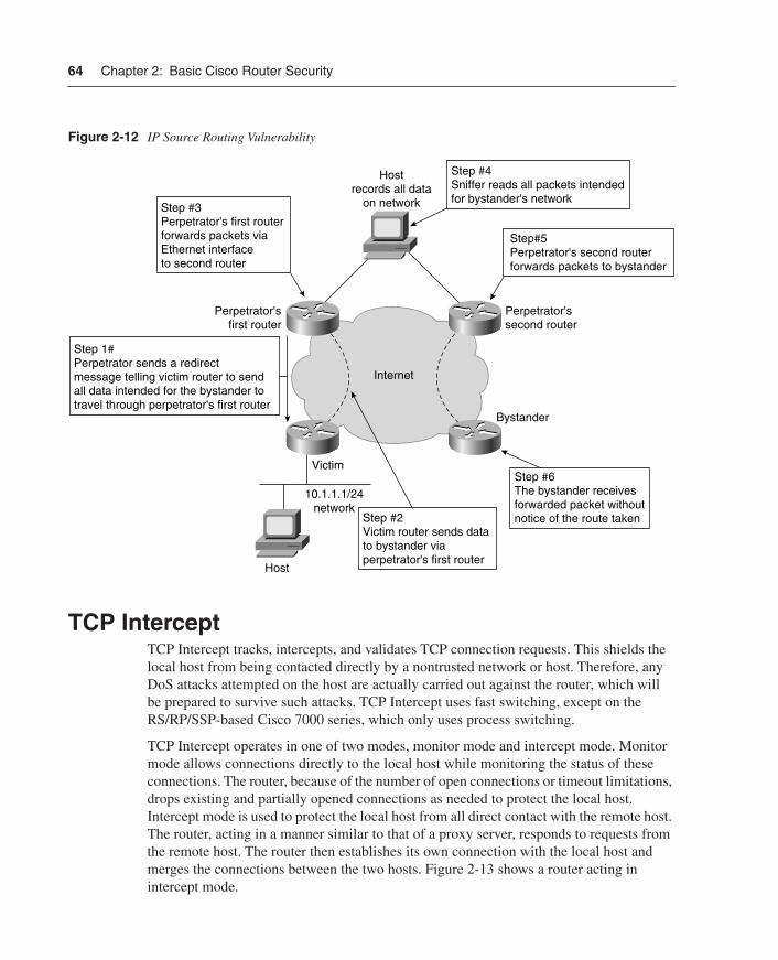
IP Source RoutingThe Cisco IOS is designed to examine the options within the header of every IP packet. According to RFC 791, these options can include Loose Source Route, Record Route, or Time Stamp. When the IOS receives a packet with one of these options enabled, it responds appropriately. If the packet contains an invalid option, the router sends an ICMP parameter problem message to the source and discards the packet. If the packet contains the source route option, it is interpreted to mean that the packet is requesting a specific route through the network. Although the default is to use source routing, ISPs usually do not want the customer deciding how to route through the network. Also, IP source routing has a number of known security problems. The main security problem is that a remote entity controls where data travels, meaning that it is possible for data to travel through a hacker’s network before going on to its ultimate destination. The hacker is able to record all data intended for another network. Figure 2-12 shows an example.
IP source routing can be disabled with the following command:
no ip source-route
SS.book Page 63 Wednesday, May 2, 2001 2:11 PM
64 Chapter 2: Basic Cisco Router Security
Figure 2-12 IP Source Routing Vulnerability
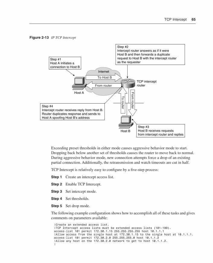
TCP InterceptTCP Intercept tracks, intercepts, and validates TCP connection requests. This shields the local host from being contacted directly by a nontrusted network or host. Therefore, any DoS attacks attempted on the host are actually carried out against the router, which will be prepared to survive such attacks. TCP Intercept uses fast switching, except on the RS/RP/SSP-based Cisco 7000 series, which only uses process switching.
TCP Intercept operates in one of two modes, monitor mode and intercept mode. Monitor mode allows connections directly to the local host while monitoring the status of these connections. The router, because of the number of open connections or timeout limitations, drops existing and partially opened connections as needed to protect the local host. Intercept mode is used to protect the local host from all direct contact with the remote host. The router, acting in a manner similar to that of a proxy server, responds to requests from the remote host. The router then establishes its own connection with the local host and merges the connections between the two hosts. Figure 2-13 shows a router acting in intercept mode.
Bystander
Victim
Internet
Perpetrator'sfirst router
Perpetrator'ssecond router
Hostrecords all data
on network
Step 1#Perpetrator sends a redirectmessage telling victim router to sendall data intended for the bystander totravel through perpetrator's first router
10.1.1.1/24network
Step #2Victim router sends datato bystander via perpetrator's first router
Step #3Perpetrator's first routerforwards packets viaEthernet interfaceto second router
Host
Step#5Perpetrator's second routerforwards packets to bystander
Step #4Sniffer reads all packets intendedfor bystander's network
Step #6The bystander receivesforwarded packet withoutnotice of the route taken
SS.book Page 64 Wednesday, May 2, 2001 2:11 PM
TCP Intercept 65
Figure 2-13 IP TCP Intercept
Exceeding preset thresholds in either mode causes aggressive behavior mode to start. Dropping back below another set of thresholds causes the router to move back to normal. During aggressive behavior mode, new connection attempts force a drop of an existing partial connection. Additionally, the retransmission and watch timeouts are cut in half.
TCP Intercept is relatively easy to configure by a five-step process:
Step 1 Create an intercept access list.
Step 2 Enable TCP Intercept.
Step 3 Set intercept mode.
Step 4 Set thresholds.
Step 5 Set drop mode.
The following example configuration shows how to accomplish all of these tasks and gives comments on parameters available:
!Create an extended access list.!TCP Intercept access lists must be extended access lists (101–199).access-list 101 permit 172.30.1.15 255.255.255.255 host 10.1.1.1!Allow access from the single host at 172.30.1.15 to the single host at 10.1.1.1.access-list 101 permit 172.30.2.0 255.255.255.0 host 10.1.1.2!Allow any host on the 172.30.2.0 network to get to host 10.1.1.2.!
TCP intercept router
Internet
Host B
Host A
To Host B
From router
From
router
To router
Step #1Host A initiates a connection to Host B
Step #4Intercept router receives reply from Host B.Router duplicates response and sends toHost A spoofing Host B's address
Step #3Host B receives requestsfrom intercept router and replies
Step #2Intercept router answers as if it wereHost B and then forwards a duplicaterequest to Host B with the intercept routeras the requester
SS.book Page 65 Wednesday, May 2, 2001 2:11 PM

66 Chapter 2: Basic Cisco Router Security
!Enable TCP Intercept.ip tcp intercept list 101!Starts IP Intercept for the hosts listed as permitted in access list 101.!!Set the intercept mode.ip tcp intercept mode intercept!Sets the mode to intercept. The other possible mode is watch.!!Set the thresholds.ip intercept connection-timeout 3600!Connections will be reset after 3600 seconds (1 hour) of no activity.!The default is 86400 seconds (24 hours).!ip tcp intercept finrst-timeout 3!Sets the time in seconds (3) after receiving a reset or FIN that the connection!remains managed. The minimum is 1 second. The default is 5 seconds.!ip tcp intercept max-incomplete high 900!Sets the maximum number of half-open connections (900) before the router goes!into aggressive behavior mode. The default is 1100. The maximum is 2147483647.!The minimum is 1.!ip tcp intercept max-incomplete low 700!Sets the number of half-open connections (700) below which the router leaves!aggressive behavior mode. The default is 900. The maximum is 2147483647.!The minimum is 1.!ip tcp intercept one-minute high 800!Sets the maximum number of connection requests (800) that may be received in a!one-minute period before the router goes into aggressive behavior mode.!The default is 1100. The maximum is 2147483647. The minimum is 1.!ip tcp intercept one-minute low 600!Sets the number of connection requests (600) that may be received in a!one-minute period below which the router leaves aggressive behavior mode.!The default is 900. The maximum is 2147483647. The minimum is 1.!ip tcp intercept watch-timeout 20!Sets the time in seconds (20) for a partially opened connection to complete!the connection sequence before sending a reset command to the local host.!!Set the drop mode.ip tcp intercept drop-mode random!Sets the drop mode (random) to randomly choose which half-open connection!while in aggressive behavior mode. The default (oldest) will drop the oldest!partial connection first.
SummaryThis chapter explores the basic configurations and practices that will help prevent the most obvious forms of attack from affecting your network. There are some very specific commands that most, if not all, administrators should employ, at least on their external routers.
No book can possibly tell you exactly how your routers should be configured. If there were, we would all be out of jobs. Every network is different and requires configurations that reflect the organization’s unique goals and needs. Use this chapter as a guideline for the options available while setting up your routers. Some of the items discussed should be set on every router, no matter what the circumstances of your particular network. The
SS.book Page 66 Wednesday, May 2, 2001 2:11 PM
Summary 67
configuration on other items will depend on the individual variations within networks and what you are trying to accomplish. Knowing the options that are available and how they operate can help administrators protect their networks from most intrusions.
A recurring theme is presented in this chapter that should be carefully considered while configuring routers: If a service is not needed, it should not be run. If a service is needed only on the internal network, do not run it on the external network. This is especially true of ICMP services. Restricting how ICMP messages are handled might protect not only your own network, but also some other administrator’s network.
To give a concise overview of the salient configurations explored in this chapter, the following sections show sample configurations that incorporate all of the suggested settings. Remember that some of these commands might not be viable on your routers because of internally used IP addresses and special circumstances within your network. However, they will still serve as a guideline for your configurations. Review the following configurations before moving on to Chapter 3, “Overview of the Cisco Security Solution and the Cisco Secure Product Family.”
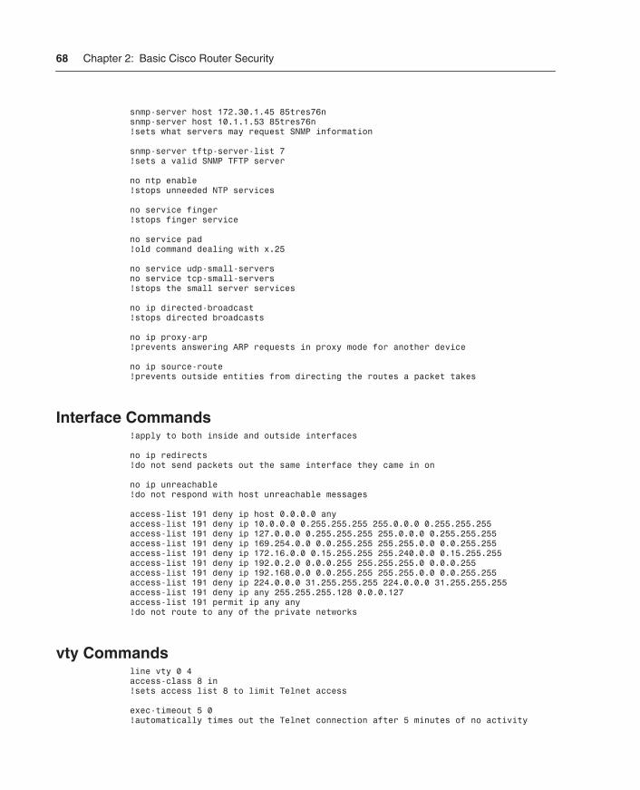
Global Commandsno enable password!prevents the older non-secure enable password from being used
enable secret level 7 9%ad100gbellisnon!uses a secret password that follows the rules for passwords
service router-encryption!encrypts the passwords
no cdp enable!prevents CDP from sending information
access-list 7 permit 172.30.1.45access-list 7 permit 10.1.1.53!sets up access list 7 for use with SNMP
access-list 8 permit 172.30.1.45access-list 8 permit 10.1.1.53access-list 8 deny any!sets up access list 8 for use with telnet on vty 0 through 4
snmp-server community 85tres76n RO 7!sets the version 1 community name (use version 2 if possible)
snmp-server trap-source Loopback0snmp-server trap-authenticationsnmp-server enable traps configsnmp-server enable traps envmonsnmp-server enable traps bgpsnmp-server enable traps frame-relay!sets the SNMP traps
snmp-server contact Joe Admin [[email protected]]snmp-server location main server room router 8!sets the contact information following the password rules
SS.book Page 67 Wednesday, May 2, 2001 2:11 PM
68 Chapter 2: Basic Cisco Router Security
snmp-server host 172.30.1.45 85tres76nsnmp-server host 10.1.1.53 85tres76n!sets what servers may request SNMP information
snmp-server tftp-server-list 7!sets a valid SNMP TFTP server
no ntp enable!stops unneeded NTP services
no service finger!stops finger service
no service pad!old command dealing with x.25
no service udp-small-serversno service tcp-small-servers!stops the small server services
no ip directed-broadcast!stops directed broadcasts
no ip proxy-arp!prevents answering ARP requests in proxy mode for another device
no ip source-route!prevents outside entities from directing the routes a packet takes
Interface Commands!apply to both inside and outside interfaces
no ip redirects!do not send packets out the same interface they came in on
no ip unreachable!do not respond with host unreachable messages
access-list 191 deny ip host 0.0.0.0 anyaccess-list 191 deny ip 10.0.0.0 0.255.255.255 255.0.0.0 0.255.255.255access-list 191 deny ip 127.0.0.0 0.255.255.255 255.0.0.0 0.255.255.255access-list 191 deny ip 169.254.0.0 0.0.255.255 255.255.0.0 0.0.255.255access-list 191 deny ip 172.16.0.0 0.15.255.255 255.240.0.0 0.15.255.255access-list 191 deny ip 192.0.2.0 0.0.0.255 255.255.255.0 0.0.0.255access-list 191 deny ip 192.168.0.0 0.0.255.255 255.255.0.0 0.0.255.255access-list 191 deny ip 224.0.0.0 31.255.255.255 224.0.0.0 31.255.255.255access-list 191 deny ip any 255.255.255.128 0.0.0.127access-list 191 permit ip any any!do not route to any of the private networks
vty Commandsline vty 0 4access-class 8 in!sets access list 8 to limit Telnet access
exec-timeout 5 0!automatically times out the Telnet connection after 5 minutes of no activity
SS.book Page 68 Wednesday, May 2, 2001 2:11 PM