Thermoelectric Cooling Systems Design Guide
21
Thermoelectric Cooling Systems Design Guide 1998 Marlow Industries, Inc Marlow Industries reserves the right to change and distribute this document without notice. Additional copies of this publication can be obtained by contacting the corporate headquarters in the United States at (214) 340-4900. Publication Number 017-7939 Rev 1 marlow industries, inc.
description
Thermoelectric Cooling Systems Design GuideA thermoelectric cooler (TEC) is a small heat pump which has the advantage of no moving parts. TEC's areused in various applications where space limitations and reliability are paramount and CFC's are notdesired. The coolers operate on direct current and may be used for heating or cooling by reversing thedirection of current flow. This is achieved by moving heat from one side of the module to the other withcurrent flow and the laws of thermodynamics.
Transcript of Thermoelectric Cooling Systems Design Guide

Thermoelectric Cooling Systems
Design Guide
1998 Marlow Industries, Inc
Marlow Industries reserves the right to change and distribute this document
without notice. Additional copies of this publication can be obtained by
contacting the corporate headquarters in the United States at (214) 340-4900.
Publication Number 017-7939 Rev 1
marlow industries, inc.

Table of Contents
Section Content Page
I. Introduction 1
II. Applications 1
III. Estimating Heat Loads 2
IV. TEC Selection Guide 6
V. Estimate TEC Performance 8
VI. Heat Sinks 10
VII. Power Supplies 11
VIII. TEC Mounting Methods 14
Thermoelectric Cooling Systems
Design Guide

Marlow Industries, Inc • Dallas, Texas 75238-1645 • (214) 340-4900 Page 1
I. Introduction
A thermoelectric cooler (TEC) is a small heat pump which has the advantage of no moving parts. TEC's areused in various applications where space limitations and reliability are paramount and CFC's are notdesired. The coolers operate on direct current and may be used for heating or cooling by reversing thedirection of current flow. This is achieved by moving heat from one side of the module to the other withcurrent flow and the laws of thermodynamics. A typical single stage cooler (Figure 1) consists of twoceramic plates with p- and n-type semiconductor material (bismuth telluride) between the plates. Theelements of semiconductor material are connected electrically in series and thermally in parallel.
Typical Single Stage CoolerFigure 1
When a positive DC current is applied to the n-type thermoelement, electrons pass from the p- to the n-typethermoelement and the cold side temperature decreases as heat is absorbed. This heat is transferred to thehot side of the cooler, where it is dissipated into the heat sink and surrounding environment. The heatabsorption (cooling) is proportional to the current and the number of thermoelectric couples.
The theories behind the operation of thermoelectric coolers can be traced back to the early 1800s.Jean Peltier discovered there is a heating or cooling effect when electric current passes through twoconductors. Thomas Seebeck found two dissimilar conductors at different temperatures would create anelectromotive force or voltage. William Thomson (Lord Kelvin) showed that over a temperature gradient asingle conductor with current flow will have reversible heating and cooling. With these principles in mindand the introduction of semiconductor materials in the late 1950s, thermoelectric cooling has become aviable technology for small cooling applications.
II. Applications
Applications can be found in many markets and industries: military, telecommunications, commercial,laboratory, medical, and aerospace. Heat pumping rates typically range from a few milliwatts to hundreds ofwatts. Projects have been undertaken where heat removal was measured in kilowatts, however, these largescale applications are not typical.
Page 2 Marlow Industries, Inc. • Dallas, Texas 75238-1645 • (214) 340-4900
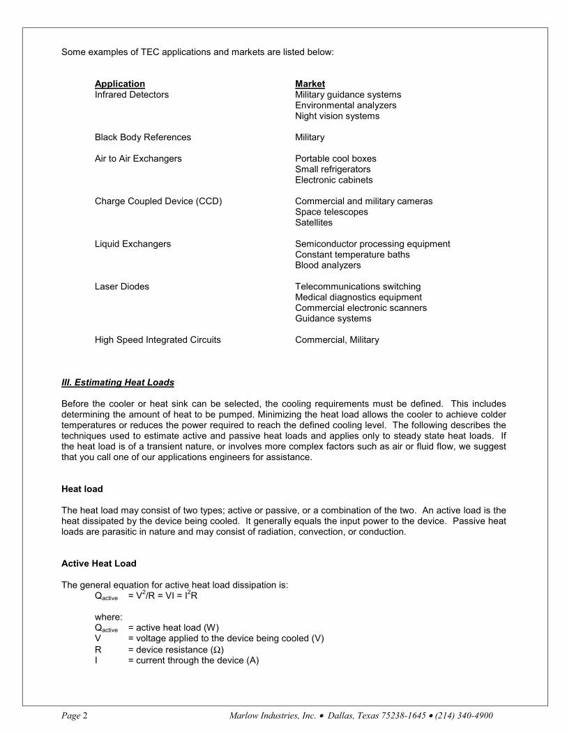
Some examples of TEC applications and markets are listed below:
Application MarketInfrared Detectors Military guidance systems
Environmental analyzersNight vision systems
Black Body References Military
Air to Air Exchangers Portable cool boxesSmall refrigeratorsElectronic cabinets
Charge Coupled Device (CCD) Commercial and military cameras Space telescopesSatellites
Liquid Exchangers Semiconductor processing equipmentConstant temperature bathsBlood analyzers
Laser Diodes Telecommunications switchingMedical diagnostics equipmentCommercial electronic scannersGuidance systems
High Speed Integrated Circuits Commercial, Military
III. Estimating Heat Loads
Before the cooler or heat sink can be selected, the cooling requirements must be defined. This includesdetermining the amount of heat to be pumped. Minimizing the heat load allows the cooler to achieve coldertemperatures or reduces the power required to reach the defined cooling level. The following describes thetechniques used to estimate active and passive heat loads and applies only to steady state heat loads. Ifthe heat load is of a transient nature, or involves more complex factors such as air or fluid flow, we suggestthat you call one of our applications engineers for assistance.
Heat load
The heat load may consist of two types; active or passive, or a combination of the two. An active load is theheat dissipated by the device being cooled. It generally equals the input power to the device. Passive heatloads are parasitic in nature and may consist of radiation, convection, or conduction.
Active Heat Load
The general equation for active heat load dissipation is:Qactive = V2/R = VI = I2R
where:Qactive = active heat load (W)V = voltage applied to the device being cooled (V)R = device resistance (Ω)I = current through the device (A)
Marlow Industries, Inc • Dallas, Texas 75238-1645 • (214) 340-4900 Page 3
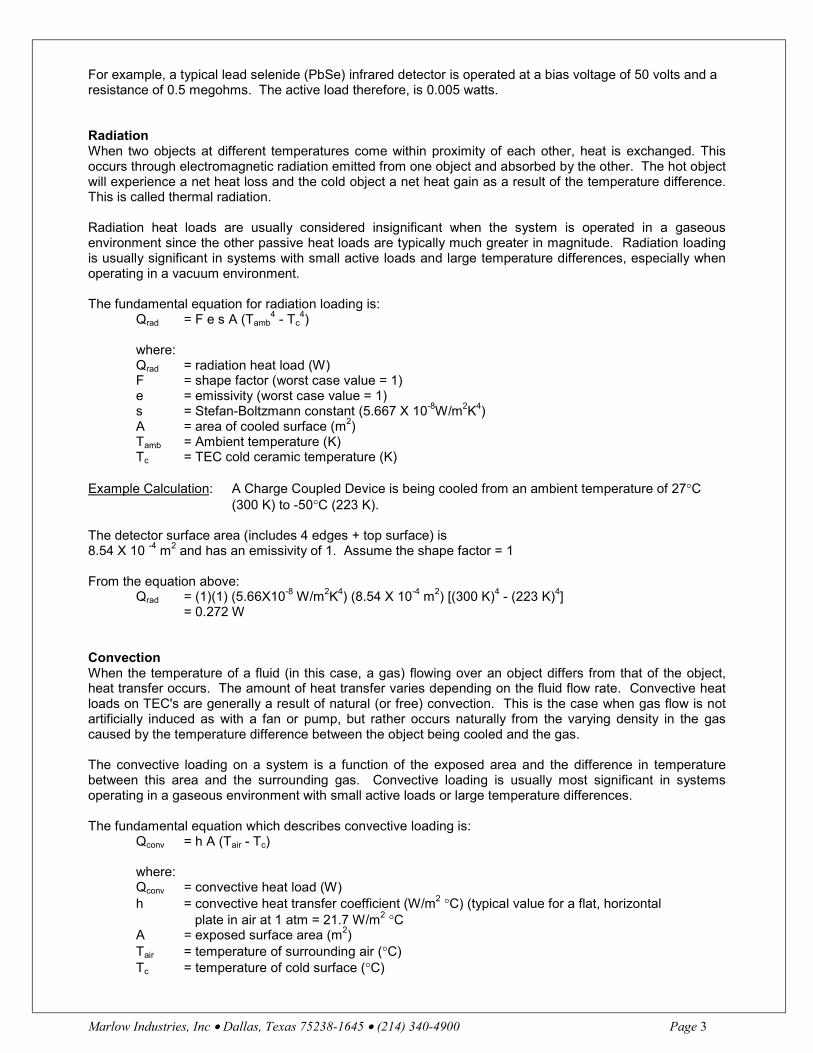
For example, a typical lead selenide (PbSe) infrared detector is operated at a bias voltage of 50 volts and aresistance of 0.5 megohms. The active load therefore, is 0.005 watts.
RadiationWhen two objects at different temperatures come within proximity of each other, heat is exchanged. Thisoccurs through electromagnetic radiation emitted from one object and absorbed by the other. The hot objectwill experience a net heat loss and the cold object a net heat gain as a result of the temperature difference.This is called thermal radiation.
Radiation heat loads are usually considered insignificant when the system is operated in a gaseousenvironment since the other passive heat loads are typically much greater in magnitude. Radiation loadingis usually significant in systems with small active loads and large temperature differences, especially whenoperating in a vacuum environment.
The fundamental equation for radiation loading is:Qrad = F e s A (Tamb
4 - Tc4)
where:Qrad = radiation heat load (W)F = shape factor (worst case value = 1)e = emissivity (worst case value = 1)s = Stefan-Boltzmann constant (5.667 X 10⁻⁸W/m2K4)A = area of cooled surface (m2)Tamb = Ambient temperature (K)Tc = TEC cold ceramic temperature (K)
Example Calculation: A Charge Coupled Device is being cooled from an ambient temperature of 27°C(300 K) to -50°C (223 K).
The detector surface area (includes 4 edges + top surface) is8.54 X 10 -4 m2 and has an emissivity of 1. Assume the shape factor = 1
From the equation above:Qrad = (1)(1) (5.66X10⁻⁸ W/m2K4) (8.54 X 10⁻⁴ m2) [(300 K)4 - (223 K)4]
= 0.272 W
ConvectionWhen the temperature of a fluid (in this case, a gas) flowing over an object differs from that of the object,heat transfer occurs. The amount of heat transfer varies depending on the fluid flow rate. Convective heatloads on TEC's are generally a result of natural (or free) convection. This is the case when gas flow is notartificially induced as with a fan or pump, but rather occurs naturally from the varying density in the gascaused by the temperature difference between the object being cooled and the gas.
The convective loading on a system is a function of the exposed area and the difference in temperaturebetween this area and the surrounding gas. Convective loading is usually most significant in systemsoperating in a gaseous environment with small active loads or large temperature differences.
The fundamental equation which describes convective loading is:Qconv = h A (Tair - Tc)
where:Qconv = convective heat load (W)h = convective heat transfer coefficient (W/m2 °C) (typical value for a flat, horizontal plate in air at 1 atm = 21.7 W/m2 °CA = exposed surface area (m2)Tair = temperature of surrounding air (°C)Tc = temperature of cold surface (°C)

Page 4 Marlow Industries, Inc. • Dallas, Texas 75238-1645 • (214) 340-4900
Example Calculation: A square plate is being cooled from 25°C to 5°C. The top and four sides are exposedsurfaces. The plate is 0.006 meters thick and each side is 0.1 meters long.
From the Convection equation:Qconv = (21.7 W/m2°C) (0.0124 m2)(25°C - 5°C)
= 5.4 W
It is very important to avoid allowing condensation to form when cooling below the dew point. This problemmay be avoided by enclosing the cooling system in a dry gas or a vacuum environment.
Conduction
Conductive heat transfer occurs when energy exchange takes place by direct impact of molecules movingfrom a high temperature region to a low temperature region.
Conductive heat loading on a system may occur through lead wires, mounting screws, etc., which form athermal path from the device being cooled to the heat sink or ambient environment.
The fundamental equation which describes conductive loading is:Qcond =k A ∆T
Lwhere:Qcond = conductive heat load (W)k = thermal conductivity of the material (W/m °C)A = cross-sectional area of the material (m2)L = length of the heat path (m)∆T = temperature difference across the heat path (°C) (usually ambient or heat sink
temperature minus cold side temperature)
Table IThermal Conductivities of Various Wire Material
Material Thermal Conductivity (W / m°C)
Aluminum 205Copper 386
Gold 315Platinum (90%) Iridium (10%) 31.1
Platinum 70.9Manganin 22.2
Example Calculation: A TEC is used as a black body reference. A temperature sensor isattached to the cold surface of the TEC. It has two platinum leads which have a diameter of25µm and are 12 mm long. These leads are attached to pins on the heat sink. The coldplate is at -20°C while the heat sink is at 30°C.
The known parameters are: k = 70.9 W/m°C, from Table I ∆T = [30°C - (-20°C)] = 50°C A(1 wire) = πd2 / 4 = π (25 µm)2 / 4
= 4.91 X 10 -10 m2
A(2 wires) = (2)(4.91 X 10 -10m2) = 9.82 X 10 -10 m2
L = 12mm = 0.012m
From the equation above:Qcond = [(70.9 W/m°C) (9.82 X 10⁻¹⁰ m2)] (50°C) / (0.012m)
= 0.0003 W

Marlow Industries, Inc • Dallas, Texas 75238-1645 • (214) 340-4900 Page 5
Since the conductive load is inversely proportional to the length of the wire, it can bereduced by using longer wires.
Combined Convection and Conduction
The following equation can be used for estimating heat losses due to convection and conduction of anenclosure.
Q passive = (A x ∆T)/(x/k + 1/h)
where:Qpassive = heat load (W)A = total external surface area of enclosure (m2)x = thickness of insulation (m)k = thermal conductivity of insulation (W/m °C)h = convective heat transfer coefficient (W/m2 °C)
∆T = Temperature change (°C)
Table IITypical Values of Convection Heat Transfer Coefficient
Process h (W / m2 °C)
Free Convection – Air 2 – 25Forced Convection – Air 25 – 250
Table IIITypical Values of Thermal Conductivity for Insulation
Product Thermal ConductivityW / m °C
Styrofoam .031Polystyrene .037
Polyurethane .039
Transient Temperature
Some designs require a set amount of time to reach the desired temperature. The following equation maybe used to estimate the time required:
t = [(ρ) (V) (Cp) (T1 - T2)]/Q
where:t = time (seconds)ρ = density (g/cm3)V = volume (cm3)Cp = specific heat (J/g °C)T1-T2 = temperature change (°C)Q = (Qto + Qtt) / 2 (J/s; Note: 1 J/s = 1 W)
Q(to) is the initial heat pumping capacity when the temperature difference across the cooler is zero. Q(tt) isthe heat pumping capacity when the desired temperature difference is reached and heat pumping capacityis decreased. Q(to) and Q(tt) are used to obtain an average value.
Page 6 Marlow Industries, Inc. • Dallas, Texas 75238-1645 • (214) 340-4900
Heat loading may occur through one or more of four modes: active, radiation, convection or conduction. Byutilizing these equations you can estimate your heat loads. The resulting information can then be used toselect a suitable TEC for your application (see section IV).
IV. TEC Selection Procedure
Outlined below is a simplified selection procedure devised to allow the user to obtain initial designs andestimates of performance for single and two-stage thermoelectric coolers. Because of the non-linearbehavior of TEC's and the number of variables involved in analyzing them, they can be designed andmodeled more accurately by our experienced engineers using Marlow Industries' internally developedcomputer software. For selection of coolers with more than two stages, or if more precision is required,please consult one of our application engineers. Once the decision to use a thermoelectric cooler has beenmade, the actual selection of suitable modules is relatively simple.
The following pages outline a step by step procedure that will take you through determining your heat load,required ∆T, and the number of stages required to meet the ∆T.
Once you have completed the analysis you will have narrowed the field of suitable TEC's to two or three.You may then proceed to steps 5 through 10 to determine the performance of the selected TEC's within yourapplication requirements.
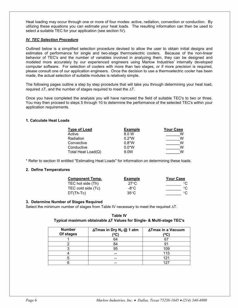
1. Calculate Heat Loads
Type of Load Example Your CaseActive 8.0 W WRadiation 0.2*W WConvective 0.8*W WConductive 0.0*W WTotal Heat Load(Q) 9.0W W
* Refer to section III entitled "Estimating Heat Loads" for information on determining these loads.
2. Define Temperatures
Component Temp. Example Your CaseTEC hot side (Th) 27°C _______ °CTEC cold side (Tc) -8°C _______ °CDT(Th-Tc) 35°C _______ °C
3. Determine Number of Stages RequiredSelect the minimum number of stages from Table IV necessary to meet the required ∆T.
Table IVTypical maximum obtainable ∆∆∆∆T Values for Single- & Multi-stage TEC's
NumberOf stages
∆∆∆∆Tmax in Dry N2 @ 1 atm(°°°°C)
∆∆∆∆Tmax in a Vacuum(°°°°C)
1 64 672 84 913 95 1094 -- 1155 -- 1216 -- 127
Marlow Industries, Inc • Dallas, Texas 75238-1645 • (214) 340-4900 Page 7
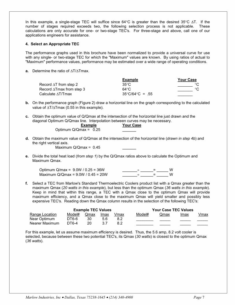
In this example, a single-stage TEC will suffice since 64°C is greater than the desired 35°C ∆T. If thenumber of stages required exceeds two, the following selection process is not applicable. Thesecalculations are only accurate for one- or two-stage TEC's. For three-stage and above, call one of ourapplications engineers for assistance.
4. Select an Appropriate TEC
The performance graphs used in this brochure have been normalized to provide a universal curve for usewith any single- or two-stage TEC for which the "Maximum" values are known. By using ratios of actual to"Maximum" performance values, performance may be estimated over a wide range of operating conditions.
a. Determine the ratio of ∆T/∆Tmax.
Example Your CaseRecord ∆T from step 2 35°C _______ °CRecord ∆Tmax from step 3 64°C _______ °CCalculate ∆T/Tmax 35°C/64°C = .55 _______
b. On the performance graph (Figure 2) draw a horizontal line on the graph corresponding to the calculatedvalue of ∆T/∆Tmax (0.55 in this example).
c. Obtain the optimum value of Q/Qmax at the intersection of the horizontal line just drawn and thediagonal Optimum Q/Qmax line. Interpolation between curves may be necessary.
Example Your Case Optimum Q/Qmax = 0.25
d. Obtain the maximum value of Q/Qmax at the intersection of the horizontal line (drawn in step 4b) andthe right vertical axis.
Maximum Q/Qmax = 0.45
e. Divide the total heat load (from step 1) by the Q/Qmax ratios above to calculate the Optimum andMaximum Qmax.
Optimum Q/max = 9.0W / 0.25 = 36W ÷ = WMaximum Q/Qmax = 9.0W / 0.45 = 20W ÷ = W
f. Select a TEC from Marlow's Standard Thermoelectric Coolers product list with a Qmax greater than themaximum Qmax (20 watts in this example), but less than the optimum Qmax (36 watts in this example).Keep in mind that within this range, a TEC with a Qmax close to the optimum Qmax will providemaximum efficiency, and a Qmax close to the maximum Qmax will yield smaller and possibly lessexpensive TEC's. Reading down the Qmax column results in the selection of the following TEC's:
Example TEC Values Your Case TEC Values Range Location Model# Qmax Imax Vmax Model# Qmax Imax Vmax Near Optimum DT6-6 30 5.6 8.2 ________ _____ _____ _____ Nearer Maximum DT6-4 20 3.7 8.2 ________ _____ _____ _____
For this example, let us assume maximum efficiency is desired. Thus, the 5.6 amp, 8.2 volt cooler isselected, because between these two potential TEC's, its Qmax (30 watts) is closest to the optimum Qmax(36 watts).

Page 8 Marlow Industries, Inc. • Dallas, Texas 75238-1645 • (214) 340-4900
FIGURE 2
V. Estimate TEC Performance
1. TEC Performance Parameters
Now that the TEC has been selected, the next step is to determine its performance.
a. Refer again to the Table of Standard Thermoelectric Coolers and record the maximum values for theTEC whose performance is being evaluated. Note that if a hot-side temperature other than 27°C is used, theperformance parameters must be adjusted to obtain more accurate results. Please call one of ourapplications engineers for assistance.
Example Your CaseTEC Minimum Values
∆Tmax 65° C °CQmax 30 W WImax 5.6 A AVmax 8.2 V V
b. Determine the ratio of ∆T/∆Tmax:∆T(from step 2) 35° C °C∆Tmax (from step 1a) 65° C °C∆T/Tmax (calculate) 35/65= .54 °C
c. On the performance graph (See Figure 3 ) draw a horizontal line on the upper graph corresponding to the∆T/∆Tmax (0.54 in this example).
d. Divide the total heat load (from step 1 of the TEC Selection Procedure) by the value of Qmax for the TECselected (from step 1a):
Q/Qmax = 9.0 W / 30 W = 0.3 = W ÷ W = ____
e. At the intersection of the horizontal line (drawn in step 1c) and the value of Q/Qmax (just calculated instep 1d), plot a vertical line on the performance graph.
f. Record the value of I/Imax at the intersection of the vertical line just plotted and the bottom I/Imax axis.
I/Imax = 0.6 I/Imax = _______

Marlow Industries, Inc • Dallas, Texas 75238-1645 • (214) 340-4900 Page 9
2. Calculate TEC Current
Using the value of Imax (obtained in step 1a) and the value of I/Imax (just obtained in step 1f ), calculate theTEC current (I).
TEC current = (Imax) X (I/Imax) = 5.6A X 0.6 = 3.4 A = A X = A
3. Calculate the TEC Voltage
a. Draw a horizontal line through each of the intersections of the vertical line (drawn in step 1e) and the twocurves in the lower half of the performance curve in Figure 3.
b. Record the values of V/Vmax at the intersection of the two horizontal lines drawn and the left verticalaxis. These values determine the range of V/Vmax for the TEC selected. For large ∆Ts (small values ofQ/Qmax), the voltage will correspond to the high end of the range, and for small ∆Ts (large values ofQ/Qmax), the voltage will correspond to the low end of the range.
Example Your CaseHigh V/Vmax = 0.68 __________Low V/Vmax = 0.54 __________
c. Multiply Vmax (obtained in step 1a) by each value of V/Vmax just obtained to get the range of TECvoltage.
High TEC Voltage = Vmax X (V/Vmax)= 8.2V X 0.68 = 5.6V V X = V
Low TEC Voltage = Vmax X (V/Vmax) = 8.2V X 0.54 = 4.4V
______V X = V
4. Calculate Maximum TEC Power
Multiply TEC current (from step 2) by High TEC voltage (from step 3c).
TEC Power = 3.4 A X 5.6 V = 19.0W = A X V = W
5. Calculate Power Dissipated Into the Heat Sink
The power dissipated into the heat sink is the sum of the total heat load and the input power to the TEC.
Qh = 9.0W + 19.0W = 28.0W = W + W = W
At this point you should have several candidate TEC's with their approximate performances and you arenow ready to order.

Page 10 Marlow Industries, Inc. • Dallas, Texas 75238-1645 • (214) 340-4900
Figure 3
VI. Heat Sinks
Design or selection of the heat sink is crucial to the overall thermoelectric system operation and coolerselection. All thermoelectric coolers require a heat sink and will be destroyed if operated without one. Thesystem temperature difference is typically quite different from the cooler temperature gradient. A typicaldesign parameter might be to limit the heat sink temperature rise above ambient to 10 to 20°C. The heatsink temperature directly affects the cooler hot side temperature, which in turn affects the cold sidetemperature that can be achieved with a TEC. Heat sink resistance is the measure of the ability of the sinkto dissipate the applied heat and is given by:

Marlow Industries, Inc • Dallas, Texas 75238-1645 • (214) 340-4900 Page 11
HSR = (T1 -T2)/Q
where:HSR = Thermal resistance (°C/W)T1 = Heat sink temperature (°C)T2 = Ambient or coolant input temperature (°C)Q = Heat load into heat sink (W) (includes absorbed + TEC power)
The goal of the heat sink design is to minimize thermal resistance. This is achieved through exposedsurface area and may require forced air or liquid circulation.
The following schematic shows how the heat sink resistance can be determined. Ambient temperature is27° C, the desired rise across the heat sink is 10°C, or heat sink temperature at 37°C. The load that mustbe dissipated is 10W. This gives a resistance of 10°C / 10W or 1°C / W.
The three basic types of heat sinks are: natural convective, forced convective, and liquid cooled, with liquidcooled being the most effective. Typical values of HSR for natural convective range from 0.5°C/W to 5°C/W,forced convective from 0.02°C/W to 0.5°C/W and liquid cooled from 0.005°C/W to 0.15°C/W. In general,most applications involving thermoelectric cooling require forced convective or liquid cooled heat sinks.
VII. Power Supplies
Thermoelectric coolers operate from a DC power input. These DC power supplies can range from simplebatteries to sophisticated closed loop temperature control/power supply circuits. Both linear and switchingpower supplies can be used to operate TEC's. The "quality" of the DC current is important. High quality DCcurrent is smooth and constant with very low ripple or noise. All current derived from AC sources containsripple. Ripple is significant because it can affect the performance of the TEC. Unfiltered full-rectified ACvoltage has a ripple factor of approximately 48% which can decrease the performance of the TEC by asmuch as 23%. Marlow Industries recommends limiting the ripple factor to less than 10% which will reducethe loss in performance to less than 1%. Listed on the following page are some examples of power supplycircuits.
Pulse Width Modulation
Pulse width modulation (PWM) is a power conversion technique which converts the AC line voltage to alower voltage DC signal. Pulse width modulation essentially controls the duty cycle as well as the frequencyof the power applied to the TEC.

Page 12 Marlow Industries, Inc. • Dallas, Texas 75238-1645 • (214) 340-4900
To prevent thermal cycling, most PWM circuits filter the DC output to provide a "smooth" DC component tothe TEC. The frequency of the PWM can be as low as possible to maintain a continuous smooth outputvoltage.
On / Off Control
On/Off, or thermostatic control, is the simplest and most crude technique for controlling the temperature ofthe TEC. This method of control is the least preferred. Because the power to the TEC is cycled from fullON to full OFF, thermal cycling of the TEC will occur and degrade the life of the unit.
Proportional Control
A proportional controller offers much better stability than an On/Off controller. In proportional controllersthere is always a residual error, even after the controller has settled to the final state. This error isproportional to the difference between the set-point temperature and the ambient temperature. Thefollowing diagram on page 13, is a linear bipolar proportional control circuit.

Marlow Industries, Inc • Dallas, Texas 75238-1645 • (214) 340-4900 Page 13
NOTES:1. OP - AMP2. SET CURRENT LIMIT < 2.0 AMPS. INCREASE GAIN UNTIL OUTPUT STARTS OSCILLATING, THEN CUT IN HALF. CHOOSE C1 TO OBTAIN STABILITY AT HIGH SETTINGS IN HEATING MODE. TEC IS A 2A @ 2V MAX, WHEN BASE TEMP = +27°C6. R1 IS CURRENT SENSE RESISTOR, .3 OHMS, 3 WATTS.
Proportional-Integral (PI) Control
The residual error present in the proportional controller can be eliminated by the addition of an integrator. PIcontrol is required for systems that have wide variation in either or both the thermal load and ambienttemperature.
Proportional-Integral-Derivative (PID) Control
Full PID control loops are the most complex and are less common. The PID controller adds a derivativecircuit to the PI controller which improves the transient response. This type of controller is mainly used inapplications where large thermal loads must be quickly controlled.

Page 14 Marlow Industries, Inc. • Dallas, Texas 75238-1645 • (214) 340-4900
VIII. TEC Mounting Methods
Thermoelectric coolers (TEC's) are mounted using one of three methods: adhesive bonding, compressionusing thermal grease, or solder.
In general, for a TEC with a ceramic base of 19 mm or less, you can solder or adhesive bond without fear offailure due to thermal stresses. If the TEC base is larger than 19 mm, we recommend the compressionmethod because thermal grease is not rigid and does not transfer thermal stresses.
A thin layer of copper metallization on the hot and/or cold ceramic allows soldering as a means ofattachment. Keep in mind a TEC that has no metallization on either side cannot be mounted using solder.Adhesives and greases are prone to outgassing, therefore they are not as appropriate for use in a vacuumpackage.
Surface Preparation
Surface preparation is important when using any of the assembly methods. No matter which method isused, the mounting surface should be flat to less than 0.08 mm over the TEC mounting area. In addition,the surface should be clean and free from oil, nicks and burrs. When multiple TEC's are placed in parallelthermally between common plates, the TEC thicknesses should vary no more than 0.05 mm.
Mounting with Adhesive Bonding
When to Use: When you want to permanently attach the TEC to your heat sink; when mounting withsolder is not an option; when the TEC's need to be lapped to the same height after mounting; whenmoderate thermal conductivity is required.
Step One: Because of the short amount of time needed for epoxy to set up, be certain to have your TEC'scleaned and ready to mount before mixing epoxy. Clean and prepare mounting surfaces on both the TECand heat sink using methanol, acetone, or general-use solvent.
NOTE: It is recommended that acetone and cotton swabs be available so any excess or spilled epoxy(uncured) may be quickly removed.
Step Two: Use Marlow Industries Thermally Conductive Epoxy. Follow the instructions on the packagecarefully. Be certain to mix the two pouches thoroughly or the epoxy will not cure properly.
A. Remove the epoxy pack from the protective pouch. B. Remove the divider. C. Knead well until thoroughly mixed. D. Cut a corner and dispense. The epoxy working time is approximately one hour.
CAUTION: Avoid prolonged or repeated breathing of vapor, and use with adequate ventilation. Avoidcontact with eyes, skin, or clothing. In case of contact with eyes or skin, flush immediately with plenty ofwater and get medical attention.
Step Three: Coat the ceramic of the TEC with approximately a 0.05 mm thick layer of epoxy.

Marlow Industries, Inc • Dallas, Texas 75238-1645 • (214) 340-4900 Page 15
Step Four: Place the TEC on the heat sink and gently rotate the TEC back and forth, squeezing out theexcess epoxy.
Step Five: Using a clamp or weight, apply pressure (less than 689,465 N/m2), and cure for two hours at65°C to maximize thermal and physical properties. Curing time at room temperature is 24 hours.
Mounting with the Compression Method
When to Use: When a permanent bond is not desired; when multiple TEC's are used; or when your TEC islarger than 19mm.
Step One: Prepare heat sink and cold sink surfaces by machining the module area to within +/-0.03 mm.
Step Two: Locate bolt holes in your assembly such that they are at opposite sides of the cooler between3.2mm to 12.7mm from the sides of the thermoelectric. The bolt holes should be in the same plane line asthe heat sink fins to minimize any bowing that might occur.
Step Three: The recommended hardware that should be used is: #4-40 or #6-32 stainless steel screws,Belleville or split lock type washers as well as a fiberinsulated washer to insulate the screw head from theheat sink.
Step Four: Remove all burrs. Then, clean and prepare mounting surface with methanol, acetone, orgeneral-use solvents.
Step Five: Apply a thin 0.05 mm layer of Marlow's Thermal grease to the hot side of the TEC. Place theTEC on the heat sink and rotate back and forth, squeezing out the excess thermal grease until resistance isfelt.
Step Six: Repeat step 5 and rotate cold plate back and forth, squeezing out the excess thermal grease.
Step Seven: In a two module system, torque the middle screw first. Be careful to apply torque in smallincrements, alternating between screws. In general, apply less than 1,034,198 N/m2 (N/m2 = Pascal) persquare meter of TEC area.

Page 16 Marlow Industries, Inc. • Dallas, Texas 75238-1645 • (214) 340-4900
Mounting with Solder
When to Use: When you need minimal outgassing; when the TEC is smaller than 19mm; when you need ahigh-strength junction; when high thermal conductivity is required.
IMPORTANT: The device to which the TEC is being soldered should be placed on a thermal insulator. Thiswill allow the device to become hot enough to reflow the solder. If necessary, the device may be placed ona hot plate set at 100°C to help heat it to the solder melting point.
Step One: Clean the surfaces to be soldered with methanol, acetone, or a general use solvent to removeoils and residues which would inhibit soldering.
Step Two: With a soldering iron and a new tip, pre-tin the bottom of the TEC (the side with lead wires)using Marlow Industries' Solder 96°C or 117°C and General Purpose Acid Flux. Use small amounts. Youcan heat the soldering iron to a maximum of 150°C, but extreme care must be taken since most TEC's areconstructed with 138°C (min.) solder.
CAUTION: Do not mix solders. Use a separate soldering iron (or a new tip) for each solder.
Step Three: With soldering iron, pre-tin the header or heat sink with the same solder and flux as used inpre-tinning the TEC. Use small amounts.
Step Four: To minimize flux residue, clean both the header and TEC. Rinse them first in hot water, thenscrub with Marlow Industries' Cleaning Solution and rinse again with hot water, brushing away any excessflux residue. Finally, wash with methanol and use forced air to blow dry.
Step Five: Prior to mounting the TEC to the header, add a small amount of Marlow Industries' BlueMounting Flux to the mounting site on the header.
Step Six: Hold TEC with tweezers and align on header. While doing this, maintain a steady, downwardpressure.
Step Seven: While holding the TEC in place, put the soldering iron to the header near the solder seam.When the solder junction flows, remove the soldering iron. The downward pressure on the TEC will expelexcess solder.
REMEMBER: The solder which holds the TEC together flows at 138°C (min.), so if you are using the 117°Csolder do not leave the soldering iron on the header surface too long, or you will melt the TEC solder aswell.
Step Eight: Continue holding the TEC in place until the solder solidifies.
Step Nine: Check along all four edges of the TEC, looking for voids, cracks, or bubbles. A smooth seaminsures proper thermal conduction.
Connecting Lead Wire to Header
Step One: Trim the excess wire from the TEC. Wrap the lead wires 3/4 of a turn around the connectorposts on the header.
Step Two: Using solder and Blue Mounting Flux, solder the lead wires to the wire posts. You should beable to see outlines of the wires, but they should be well covered. Wick off any excess solder with thesoldering iron.

Marlow Industries, Inc • Dallas, Texas 75238-1645 • (214) 340-4900 Page 17
Final Cleaning and Inspection
Step One: Rinse both the header and TEC in hot water, then scrub with cleaning solution and rinse againwith hot water, brushing away any excess flux residue around the pins. Wash with hot water and dry withforced air. To insure complete removal of moisture, dry the entire assembly in an oven for 30 minutes at60°C. If an oven is not available, the forced-air blower is adequate.
Step Two: Check the solder joints for cracks or bubbles.
Lead Wire Attachment
Some thermoelectric coolers use standard 2.8 mm (0.110) spade lug connectors for lead wire attachment.The spade lugs are easily attached by hand. When designing your wiring harness, we recommend that youdesign the female spade lug connector into the harness. The AMP part number for this female 2.8 mmspade lug connector is 42398-1.
Insertion Procedure: Insert female spade lug over the lead tabs. Use a side-to-side motion to secure thelug on the tab. DO NOT USE an up-and-down motion, for this can damage the tab or the tab solder joint.Insert the lug until it seats onto the tab detent.
Preventing Problems
1. Do not use excessive amounts of solder. This can short the power leads and/or inhibit a goodthermal interface.
2. Use the proper solder and flux. Marlow Industries' General Purpose Acid Flux is recommended.Without it, outgassing or overheating during soldering may occur.
3. Be sure to clean the TEC thoroughly to prevent outgassing.
4. Do not overheat the TEC with the soldering iron. Because of the narrow temperature differentialbetween the mounting solder (117°C) and the solder used in the TEC (138°C min.), care must betaken not to overheat the TEC and reflow the solder.
5. During soldering, be sure the surface on which the soldering is being done is composed of a lowthermal conductivity material. This will prevent the solder iron heat from being drawn away, whichcan cause difficulties with reflowing the solder.

Page 18 Marlow Industries, Inc. • Dallas, Texas 75238-1645 • (214) 340-4900
6. When pre-tinning a large area of the TEC, pre-tin in small sections or purchase the coolerspretinned by Marlow Industries.
7. If a TEC is being soldered to a large header, it may require that the header be placed on a 100°Chot plate. This will minimize heat conduction away from the solder point.
Table IVConversions
GIVEN USE TO GIVE
SI Unit Factor English Unit
Watt .2930711 BTU / hr
m 39.37 in
°C 1.8(°C) + 32 °F
N / m2 (Pa) .145E-03 lbs/in2

For further information or assistance in the U.S., contact:
10451 Vista Park Road Dallas TX 75238-1645 TEL: 214-340-4900 http://www.marlow.com
marlow industries, inc.