Thermal Test Report - PARTIS thermal test report/th1_ML5412-400J1.pdf · The last data point is...
15
Thermal Test Report Customer Confidential Prepared on behalf of: Eurocase on their: ML5412 400 J1 Lab Reference: PVCS 1895 Date: Tuesday, 08 February 2005 Revision 1.1 Application & Design-In Centre, EMEA
-
Upload
duongduong -
Category
Documents
-
view
215 -
download
0
Transcript of Thermal Test Report - PARTIS thermal test report/th1_ML5412-400J1.pdf · The last data point is...

Thermal Test Report
Customer Confidential
Prepared on behalf of: Eurocase
on their: ML5412 400 J1
Lab Reference: PVCS 1895
Date: Tuesday, 08 February 2005
Revision 1.1 Application & Design-In Centre, EMEA

R
Revision History
Revision Number
Description Revision Date
1.0 Initial Release. August 7th 2003
1.1 Minor Title Page Change June 2004
Disclaimer
In making any use of this test report you are expressly agreeing to the disclaimers and notices below:
THIS TEST REPORT IS PROVIDED "AS IS" WITH NO WARRANTY WHATSOEVER, WHETHER EXPRESS, IMPLIED OR STATUTORY, INCLUDING BUT NOT LIMITED TO THOSE FOR NON-INFRINGEMENT OF INTELLECTUAL PROPERTY, MERCHANTABILITY OR SATISFACTORY QUALITY, FITNESS FOR ANY PARTICULAR PURPOSE, OR ANY WARRANTY OTHERWISE ARISING OUT OF ANY PROPOSAL, RECOMMENDATION, CONCLUSION, SPECIFICATION OR SAMPLE.
THIS TEST REPORT IS CONFIDENTIAL AND SHALL NOT BE USED FOR MARKETING PURPOSES. INTEL ASSUMES NO RESPONSIBILITY FOR ANY ERRORS WHICH MAY APPEAR IN THIS TEST REPORT.
THE LIMITATIONS AND DISCLAIMERS SET OUT IN THIS TEST REPORT WERE AN ESSENTIAL ELEMENT IN INTEL AGREEING TO SUPPLY THIS TEST REPORT FREE OFCHARGE.
INFORMATION IN THIS DOCUMENT IS PROVIDED IN CONNECTION WITH INTEL® PRODUCTS. NO LICENSE, EXPRESS OR IMPLIED, BY ESTOPPEL OR OTHERWISE, TO ANY INTELLECTUAL PROPERTY RIGHTS IS GRANTED BY THIS DOCUMENT. EXCEPT AS PROVIDED IN INTEL’S TERMS AND CONDITIONS OF SALE FOR SUCH PRODUCTS, INTEL ASSUMES NO LIABILITY WHATSOEVER, AND INTEL DISCLAIMS ANY EXPRESS OR IMPLIED WARRANTY, RELATING TO SALE AND/OR USE OF INTEL PRODUCTS INCLUDING LIABILITY OR WARRANTIES RELATING TO FITNESS FOR A PARTICULAR PURPOSE, MERCHANTABILITY, OR INFRINGEMENT OF ANY PATENT, COPYRIGHT OR OTHER INTELLECTUAL PROPERTY RIGHT. Intel products are not intended for use in medical, life saving, or life sustaining applications.
Intel may make changes to specifications and product descriptions at any time, without notice.
The Springdale chipset may contain design defects or errors known as errata which may cause the product to deviate from published specifications. Current characterized errata are available on request.
Contact your local Intel sales office or your distributor to obtain the latest specifications and before placing your product order.
Intel and the Intel logo are trademarks or registered trademarks of Intel Corporation or its subsidiaries in the United States and other countries.
*Other names and brands may be claimed as the property of others.
Copyright © 2004, Intel Corporation
2 Intel Confidential

R
Contents
1 Introduction ......................................................................................................................... 5 1.1 Documentation Review & Approval........................................................................ 5
2 Test Results Summary........................................................................................................ 6 2.1 Summary of Issues................................................................................................. 6
2.1.1 Test Result.............................................................................................. 6 2.1.2 Priority 1 Critical...................................................................................... 6 2.1.3 Priority 2 Important.................................................................................. 6 2.1.4 Priority 3 Future Impact .......................................................................... 6 2.1.5 FYI........................................................................................................... 6
3 System Configuration.......................................................................................................... 7 3.1 Overview................................................................................................................. 7 3.2 Equipment Under Test ........................................................................................... 7
3.2.1 System Pictures ...................................................................................... 7 3.2.2 Thermal Solution..................................................................................... 7 3.2.3 EUT Configuration .................................................................................. 8
4 Test Methodology.............................................................................................................. 10 4.1 Thermal Test Equipment ...................................................................................... 10 4.2 Tolerance/Accuracy.............................................................................................. 10 4.3 Test Method.......................................................................................................... 11
4.3.1 Thermocouple Calibration Check ......................................................... 11 4.3.2 Thermocouple Placement..................................................................... 11 4.3.3 Test Procedure ..................................................................................... 12
5 Thermal Test Results ........................................................................................................ 13 5.1 Test Specifications & Limits ................................................................................. 13
5.1.1 Intel® Pentium® 4 Processor 530 @ 3.0GHz ...................................... 13 5.2 Test Results.......................................................................................................... 14
5.2.1 Test Equipment/Test Deviations........................................................... 14 5.2.2 Thermal Stress Test Results ................................................................ 14
6 References........................................................................................................................ 15 6.1 Thermal Support Documentation ......................................................................... 15
3 Intel Confidential

R
<This page is intentionally left blank.>
4 Intel Confidential

Introduction
R
1 Introduction This document is designed to report and evaluate the thermal performance, of the Eurocase ML5412 400 J1, Lab Reference PVCS 1895 to Intel Thermal Specifications. The equipment under test was assessed by Intel Corporation (UK) LTD, in their environmental test facilities located at
Pipers Way, Swindon, SN3 1RJ United Kingdom.
1.1 Documentation Review & Approval Date of Test Completion: Tuesday 31 Jan 2005 Date of Report: Wednesday 2 Feb 2005
Test Engineer
Imran Dhansey
Approval
Gareth Lockwood
5 Intel Confidential

Test Results Summary
R
2 Test Results Summary
2.1 Summary of Issues A summary of thermal related test issues is given below. A priority has been assigned to each problem to estimate the potential impact to users. Additionally, there may be some issues that are identified in this report as “FYI” (For Your Information) that may be of interest, but are not considered of high enough priority to be listed in the summary.
2.1.1 Test Result The equipment under test met Intel Thermal specifications.
2.1.2 Priority 1 Critical [High impact issues requiring immediate attention] N/A
2.1.3 Priority 2 Important [Issues that should be corrected] N/A
2.1.4 Priority 3 Future Impact [Issues that have little impact now. Some may have future impact] N/A
2.1.5 FYI [For Your Information. Miscellaneous information that may be of interest]
6 Intel Confidential

System Configuration
R
3 System Configuration
3.1 Overview This section lists the original configuration of the equipment under test. If any changes are required for the system to pass thermal test specification, these will be stated in section 2.1, and only the system in this configuration is recognised as a qualifying result.
3.2 Equipment Under Test
3.2.1 System Pictures
3.2.2 Thermal Solution
7 Intel Confidential
System Configuration
R
3.2.3 EUT Configuration
Manufacturer Description Model/Part Number
Serial Number
Location
Eurocase* ATX Midi Tower Chassis ML5412 400 J1 Not Known N/A
Eurocase ATX12V 400W Switching Power Supply (W/PFC)
ATX-400 JSP Not Known Top back of Chassis
Intel Intel® D915GAG µATX Desktop Motherboard
AA C64123-302
BQAG44001907
N/A
Intel Intel® Pentium® 4 Processor 530 (3.0GHz/800/HT/1MB)
BX80547PG3000E
Not Known LGA775 Socket
Samsung* 256MB DDR 400MHz PC3200 SDRAM DIMM
PC3200U-30440-A1
M368L3223DTM-CC4
Channel A DIMM 0 Channel B DIMM 0
EVGA* GeForce* FX 128MB PCI Express* Graphics Card
GF-FX-5200 Not Known PCI Express x16 Slot
Maxtor* DiamondMax* Plus 9 200GB Ultra ATA/133/ SATA 150
6Y080M0 Y2DGP7XE Internal HDD 3.5” bay
Samsung 16x IDE DVD-Rom Drive SD-616Q Not Known Top external 5.25”bay
Samsung 52x IDE CDRW/DVD Drive SM-348B Not Known Bottom external 5.25”bay
Not Known 1.44 MB Floppy Drive Not Known Not Known Internal FDD 3.5” bay
Not Known USB/Audio Daughter Board Not Known Not Known Bottom front of chassis
Full BIOS Revision EV91510A.86A.0213 Operating System Microsoft* Windows* XP Professional (SP2)
Additional information for fans, ferrites, etc fitted in the chassis
Manufacturer Description Model/ Part Number
Position in chassis
Nidec Corp* Intel Branded Processor Fan Heatsink
C25704-001 N/A Processor Cooling
Tricod Electronics*
120mm DC12V, 12A Chassis Fan
Not Known Chassis Side Panel, positioned directly above processor cooling solution
8 Intel Confidential
System Configuration
R
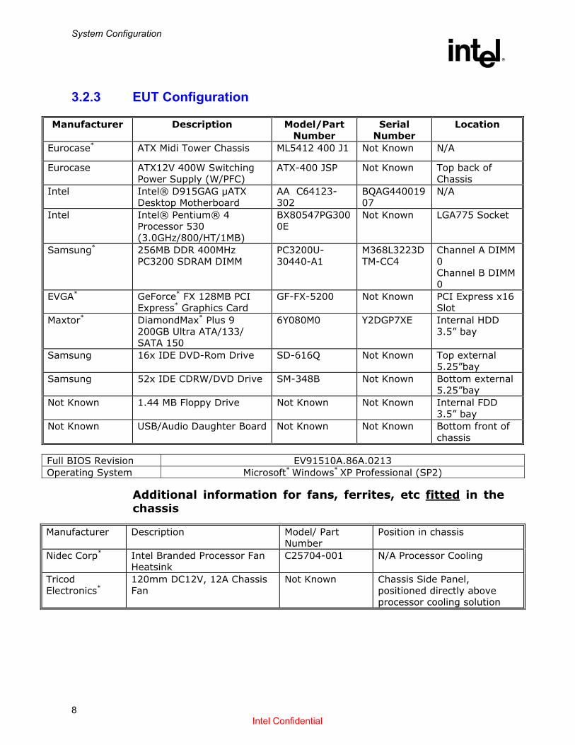
Additional parts supplied with the chassis/system for test
Manufacturer Description Model/ Part Number
Position in chassis
Xinruilian (Note: 3 Chassis fans)
80mm DC12V, 0.11A Chassis Fan
RDM8025S N/A
9 Intel Confidential

Test Methodology
R
4 Test Methodology
4.1 Thermal Test Equipment Some or all of this equipment may have been used during thermal testing.
Supplier Description Model/Part
Number
Thermotron* Walk-In Thermal Chamber WP-499-THCM-
705
Thermotron* Thermal Chamber S-8SLE
Cambridge Accusense* Airflow Monitoring Equipment
ATM-24 CAFS-220-5M
Testo* Digital Anemometer 0560.4900
Anville Instruments* Data Acquisition Unit X-435
Fluke* Hydra Data Logger 2625A
Fluke* Themocouple Calibrators 51/52 & 714
Series
FLIR Systems* Infra-Red Camera Prism
Omega* Hot-Point Cell CL950-220
4.2 Tolerance/Accuracy All thermal test equipment is maintained annually by traceable calibration. The accuracy of type T thermocouples is: -270 to +400ºC, greater of 0.5ºC or 0.4%.
10 Intel Confidential

Test Methodology
R
4.3 Test Method Thermal testing will be performed in a thermal chamber with a controlled ambient temperature of 35ºC. Case and ambient temperature measurements, Tc and Ta respectively, will be taken at 20 second intervals until thermal equilibrium (steady state) is reached. Steady state is reached when the difference between the current reading and the previous reading is less that 0.5%. Data will be collected for 5 minutes past the time determined to be steady state. The last data point is recorded in the test report with no averaging.
4.3.1 Thermocouple Calibration Check It is important to ensure that the thermocouples used for ambient and case temperature measurements are calibrated. A Hot-Point* Calibration Cell is used to check the accuracy of thermocouples prior to any thermocouple being used for testing – each thermocouple is placed in the cell and then set to 0ºC and 100ºC. The thermocouple reading should be within +/-0.5ºC of the set point.
4.3.2 Thermocouple Placement To record the ambient air temperature (Ta) measurements, place 4 thermocouples equally spaced 2.54mm (0.1”) above the fan hub vertically, halfway between the fan hub and housing horizontally (See Figure 1). Figure 1 A characterised processor will be used during testing.
11 Intel Confidential

Test Methodology
R
The case temperature (Tc) measurement will be taken with a thermocouple placed in the centre of the processor Integrated Heat Spreader (IHS). The IHS will be grooved to 0.508mm (0.02”) – 0.635mm (0.025”) deep, 0.889mm (0.035”) – 1.016mm (0.04”) wide, and half the length of the IHS. The thermocouple will be Type T, 36 gauge for processor case temperature measurement with Teflon* insulation. The thermocouple will be attached using Loctite* 315 thermally conductive adhesive in the manner shown in Figure 2 and 3. A continuity check will be performed to ensure contact between the thermocouple and the processor IHS.
Figure 2 – Top View Figure 3 – Cross Section
4.3.3 Test Procedure The BIOS of the system under test is reset to default settings where appropriate and all power saving features and system management functions are disabled. The system is then booted into the relevant Operating System and test software installed. The applications used for thermal testing are: Intel® P4MaxPower version 2.1 [set to 100% power level] Intel® Frequency Display Utility Intel® Active Monitor [if applicable] P4MaxPower is activated to stress the processor to its Thermal Design Point and at no point during the test should the processor activate it’s thermal control circuit (monitored by Frequency Display Utility). The thermocouple temperatures throughout the system are logged by the chamber control software over a period as stated in section 4.3.
12 Intel Confidential

Thermal Test Results
R
5 Thermal Test Results All pass results are within the accuracy of the test equipment (see section 4.2). Note. The power level output of different processors and processor lines can vary, this can either have a positive or negative impact on the overall Tcase temperature specification for a processor/chassis/heatsink under test, an example: A power output increase of 2.7Watts could approximately equate to an additional 1°C – 3°C* on the Tcase temperature measurement. A similar calculation can be made regarding a power output decrease. These test results are only valid for the processor tested and should only be used as an indication unless specific processor measured power is stated. *Based on the power versus max Tcase temperature increases of the P4 2.0GHz and 2.2GHz processors.
5.1 Test Specifications & Limits The information in this section is taken from the relevant processor Electrical, Mechanical & Thermal Specification document (EMTS).
5.1.1 Intel® Pentium® 4 Processor 530 @ 3.0GHz
Criteria Specificatio
n Notes
Processor Tc 67.7ºC 84W Thermal Design Power
Processor Ta 38ºC
13 Intel Confidential
Thermal Test Results
R
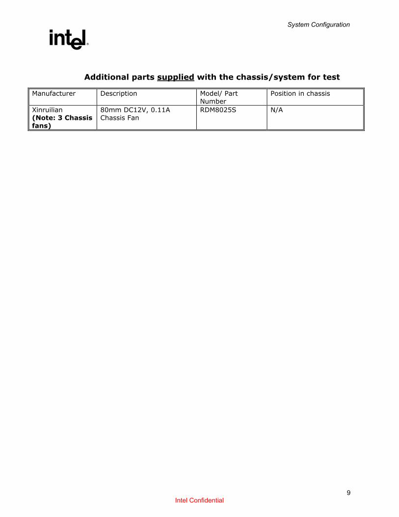
5.2 Test Results This section contains the Thermal test results for the equipment under test using the Intel® Pentium® 4 Processor 530 @ 3.0GHz, to the specification in section 5.1.1.
5.2.1 Test Equipment/Test Deviations None.
5.2.2 Thermal Stress Test Results
Monitor Point Temperature
Status
Processor Tc 65.05ºC PASS
Processor Ta 38ºC PASS
14 Intel Confidential

References
R
6 References
6.1 Thermal Support Documentation Refer to the following documentation for more information.
Relevant Intel® Processor Electrical, Mechanical & Thermal Specification (EMTS)
Relevant Intel® Processor Thermal Design Guidelines.
ATX and µATX specifications [http://www.formfactors.org]
15 Intel Confidential